6.4 mechanical, electrical, and plumbing …. fluids may leak from damaged joints or broken pipe;...
TRANSCRIPT

Available at: http://www.fema.gov/plan/prevent/earthquake/fema74/ Last Modified: January 2011
FEMA E-74 6: Seismic Protection of Nonstructural Components Page 6-220
6.4 MECHANICAL, ELECTRICAL, AND PLUMBING COMPONENTS
6.4.3 PRESSURE PIPING
6.4.3.1 SUSPENDED PRESSURE PIPING
There are many types of piping systems which convey a wide variety of fluids and gases in and around buildings. In this section, pressure piping refers to “all piping (except fire suppression piping) that carries fluids which, in their vapor stage, exhibit a pressure of 15 psi, gauge, or higher.” See Sections 6.4.4 and 6.4.5 for other piping categories. This example addresses seismic restraint details for suspended piping; see Sections 6.4.3.2 through 6.4.3.8 for other types of piping system restraints as shown in Figure 6.4.3.1-10.
TYPICAL CAUSES OF DAMAGE
Improperly supported pipes can become dislodged and fall. Pipes are particularly vulnerable to damage at joints, bends, penetrations through walls
or structural members, and connections to equipment. Unbraced piping can sway and impact adjacent items. Piping may be damaged as a result of differential movement between points of
attachment. Fluids may leak from damaged joints or broken pipe; property losses and business
outages are often attributed to fluid leaks from piping.

Available at: http://www.fema.gov/plan/prevent/earthquake/fema74/ Last Modified: January 2011
FEMA E-74 6: Seismic Protection of Nonstructural Components Page 6-221
Damage Examples
Figure 6.4.3.1-1 Pipe joint failure in the 1971 magnitude-6.6 San Fernando Earthquake (Photo courtesy of John F. Meehan).

Available at: http://www.fema.gov/plan/prevent/earthquake/fema74/ Last Modified: January 2011
FEMA E-74 6: Seismic Protection of Nonstructural Components Page 6-222
Figure 6.4.3.1-2 Leakage caused by pipe damage at joint in the 1994 magnitude-6.7 Northridge Earthquake (Photo courtesy of Degenkolb Engineers).

Available at: http://www.fema.gov/plan/prevent/earthquake/fema74/ Last Modified: January 2011
FEMA E-74 6: Seismic Protection of Nonstructural Components Page 6-223
Figure 6.4.3.1-3 Pipe brace failed at connection in 1994 Northridge Earthquake; insulation removed prior to photo (Photo courtesy of Mason Industries).

Available at: http://www.fema.gov/plan/prevent/earthquake/fema74/ Last Modified: January 2011
FEMA E-74 6: Seismic Protection of Nonstructural Components Page 6-224
SEISMIC MITIGATION CONSIDERATIONS
Details shown are for overhead attachments for suspended piping. Seismic detailing for pipes requires both transverse and longitudinal braces; while these are shown here as separate details, both types of bracing are required. The spacing of pipe bracing is dependent on the level of seismicity, location in a building, size of the pipe, type of pipe, and strength of connections to the structure.
Pressure piping systems, including their supports, may be designed either using the provisions of ASME B31 Process Piping (ASME, 2008) or ASCE/SEI 7-10, Minimum Design Loads for Buildings and Other Structures (ASCE, 2010). See Section 6.4.4 for issues related to fire protection piping systems.
ASCE/SEI 7-10 contains a number of exemptions for suspended piping where the hangers are less than 12 inches long or “high-deformability piping” is used and the pipe diameter is small (anywhere from 1- to 3-inch diameter depending on the building location and occupancy). If piping is unbraced, provisions must be made to accommodate anticipated movement (such as by providing flexible connections, as shown in Section 6.4.3.3)
Many vendors supply specialized hardware used for the seismic anchorage or sway bracing of piping systems. These vendors offer a wide variety of products and services including design, installation and inspection manuals, load tables, load rated hardware, spring loaded hangers, couplers and fittings, pipe dampers, preassembled seismic bracing kits, AUTOCAD details, calculation packages, and technical support.
Longitudinal pipe bracing requires the use of a pipe clamp, riser clamp, welded lug or device that provides positive attachment to the pipe and will not slip along the length of the pipe. Longitudinal pipe supports should not rely on friction connections such as U-bolts as these do not provide reliable longitudinal restraint during an earthquake and are likely to slip. Some vendors have items with names such as “seismic pipe clamp” or “longitudinal restraint device” that are intended for use with longitudinal restraints.
Virtual Design and Construction (VDC) and Building Information Models (BIM) involve the development of 3D computer models depicting all the structural and many nonstructural components of buildings. Increasing use of these 3D models that incorporate all the MEP systems will facilitate the design and coordination of these components with the structural system and other nonstructural components. An example of a BIM model with piping and pipe supports is shown in Figure 6.4.3.1-9.
Piping systems are typically combinations of horizontal and vertical runs of pipe; vertical runs are often called risers. Pipes may be suspended overhead as shown in this

Available at: http://www.fema.gov/plan/prevent/earthquake/fema74/ Last Modified: January 2011
FEMA E-74 6: Seismic Protection of Nonstructural Components Page 6-225
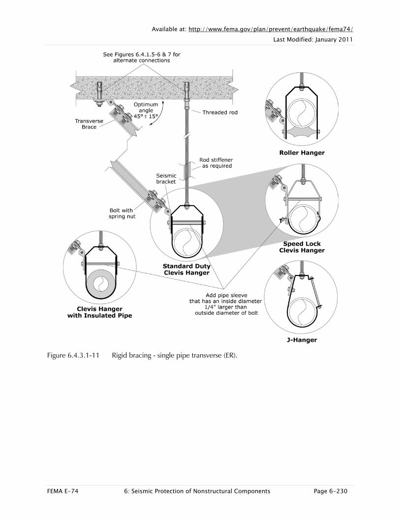
example or floor-mounted, roof-mounted, or wall-mounted. Flexible connections are often required at fixed equipment or where piping crosses an expansion joint or seismic separation. Pipe runs also typically include penetrations through floor slabs, roof slabs, and walls or structural framing. Details for many restraint conditions can be found in FEMA 414 Installing Seismic Restraints for Duct and Pipe (2004). Some of these conditions are shown in Sections 6.4.3.2 through 6.4.3.8 (See Figure 6.4.3.1-11).
Mitigation Examples
Figure 6.4.3.1-4 Single clevis hanger support with transverse cable bracing at the restraining bolt (Photo courtesy of Mason Industries).

Available at: http://www.fema.gov/plan/prevent/earthquake/fema74/ Last Modified: January 2011
FEMA E-74 6: Seismic Protection of Nonstructural Components Page 6-226
Figure 6.4.3.1-5 Pipe clamp supports with transverse and longitudinal angle braces; note pipe clamp for longitudinal brace in direct contact with pipe (Photo courtesy of Mason Industries).
Figure 6.4.3.1-6 All-directional cable bracing of suspended piping (Photo courtesy of ISAT).

Available at: http://www.fema.gov/plan/prevent/earthquake/fema74/ Last Modified: January 2011
FEMA E-74 6: Seismic Protection of Nonstructural Components Page 6-227
Figure 6.4.3.1-7 Transverse bracing with J-hanger and strut at the restraining bolt. Note that longitudinal brace shown is ineffective because the J-hanger can slip along the length of the pipe; a pipe clamp or equivalent is required for a longitudinal brace (Photo courtesy of Cynthia Perry, BFP Engineers).
Figure 6.4.3.1-8 Viscous damper used as restraint on large insulated pipe (Photo courtesy of Eduardo Fierro, BFP Engineers).

Available at: http://www.fema.gov/plan/prevent/earthquake/fema74/ Last Modified: January 2011
FEMA E-74 6: Seismic Protection of Nonstructural Components Page 6-228
Figure 6.4.3.1-9 Example of BIM Model (left) compared to installed piping (right) (Photo and image courtesy of ISAT).

Available at: http://www.fema.gov/plan/prevent/earthquake/fema74/ Last Modified: January 2011
FEMA E-74 6: Seismic Protection of Nonstructural Components Page 6-229
Mitigation Details
Figure 6.4.3.1-10 Schematic of seismic restraint conditions for piping (ER)
Available at: http://www.fema.gov/plan/prevent/earthquake/fema74/ Last Modified: January 2011
FEMA E-74 6: Seismic Protection of Nonstructural Components Page 6-230
Figure 6.4.3.1-11 Rigid bracing - single pipe transverse (ER).

Available at: http://www.fema.gov/plan/prevent/earthquake/fema74/ Last Modified: January 2011
FEMA E-74 6: Seismic Protection of Nonstructural Components Page 6-231
Figure 6.4.3.1-12 Cable bracing - single pipe transverse (ER).
Available at: http://www.fema.gov/plan/prevent/earthquake/fema74/ Last Modified: January 2011
FEMA E-74 6: Seismic Protection of Nonstructural Components Page 6-232
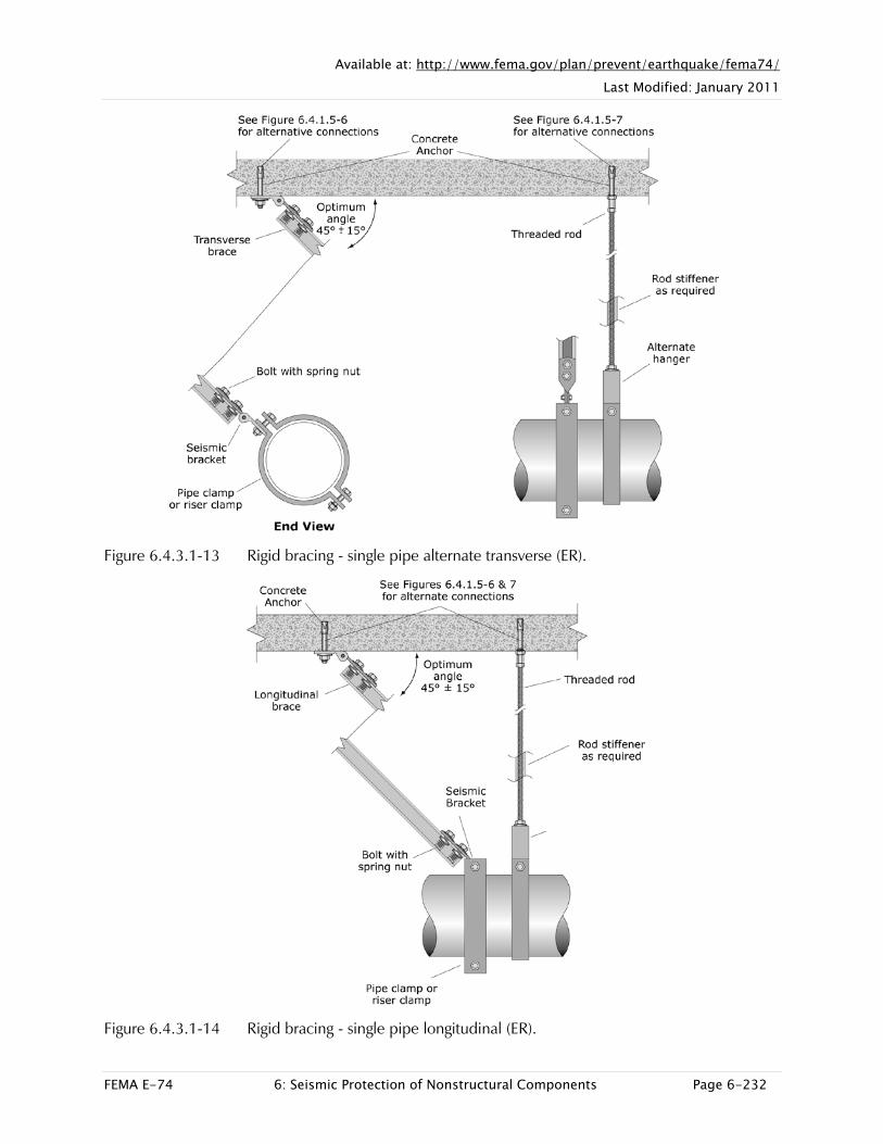
Figure 6.4.3.1-13 Rigid bracing - single pipe alternate transverse (ER).
Figure 6.4.3.1-14 Rigid bracing - single pipe longitudinal (ER).

Available at: http://www.fema.gov/plan/prevent/earthquake/fema74/ Last Modified: January 2011
FEMA E-74 6: Seismic Protection of Nonstructural Components Page 6-233
Figure 6.4.3.1-15 Rigid bracing - Trapeze supported piping (ER).
Figure 6.4.3.1-16 Cable bracing - Trapeze supported piping (ER).