6.4.4 back pressure - leser
TRANSCRIPT

66 IInnssttaallllaattiioonn aanndd PPllaanntt DDeessiiggnn
LWN 753.00 edition: 27.10.2016 6.4-3
6.4.4 Back Pressure
6.4.4.1 Definitions “Back pressure is the pressure that exists at the outlet of a pressure relief device as a result of the pressure in the discharge system. It is the sum of the superimposed and built-up back pressures and has an influence on the function of the safety valve.”17)
The type of back pressure that occurs depends on the type of installation. The simplest version of installation is a vessel with a safety valve but no connected outlet line (see Figure 6.4.4.1-1). This configuration is used for uncritical mediums like water or air and small safety valve sizes. With this configuration no additional back pressure arises.
Safety valve
Vessel
Figure 6.4.4.1-1: Without Back Pressure
Figure 6.4.4.1-2: Built-up Back Pressure
Figure 6.4.4.1-3: Superimposed Back pressure
Built-up back pressure The safety valve can also be connected to an outlet line which blows off into the open air (see Figure 6.4.4.1-2). Pressure that arises at the outlet of a safety valve and is caused by flow through the valve and the discharge system is called built-up back pressure. The diameter, the length of the discharge pipes, elbows, silencers, etc. determine the level of built-up back pressure. Excessive built-up back pressure leads to chattering of the safety valve.
Superimposed back pressure The medium can also be discharged into a closed blowdown or discharge system (see Figure 6.4.4.1-3). This is necessary when discharge in the open air is not wanted or not allowed e.g. for toxic or highly corrosive media. In this case pressure exists at the outlet of a safety valve at the time the safety valve is required to operate. This pressure is called superimposed back pressure. It is the result of pressure in the discharge system coming from other sources and may be constant or variable. Superimposed back pressure cause a change of the set pressure of a conventional safety valve.
17) API 520 Part I, 8th Edition 2008, Sect. 3.3
Back Pressure = Built-up + Superimposed
Safety valve
Vessel
Outlet line
Safety valve
Vessel
Outlet line
Blowdown System

66 IInnssttaallllaattiioonn aanndd PPllaanntt DDeessiiggnn
LWN 753.00 edition: 27.10.2016 6.4-4
6.4.4.2 Types of Back Pressure and Required Actions
Back Pressure
Built-upBack Pressure
SuperimposedBack Pressure
< 15%
≥ 15%
Constant
Variable
No action required
Balanced Bellows
Balanced Bellows
Balanced Bellows
CDTP-correction
Type of Back Pressure ActionDistinction
Figure 6.4.4.2-1: Differences of back pressure types and required actions
Depending on the type of back pressure, LESER defines different actions to avoid reductions of capacity (Figure 6.4.4.2-1). Built-up Back Pressure < 15%: LESER conventional Safety Valves are able to compensate for <15% built-up back pressure without further devices. ≥15%: To compensate for ≥15% built-up back pressure a balanced bellows has to be installed. This compensation reaches up to 50 % for safety valves of the API product group and up to 35% for all other LESER safety valves with balanced bellows Note: API 520 defines the built- up back pressure limit for conventional safety valves to 10%. Constant Superimposed Back Pressure The constant superimposed back pressure can be compensated for either by a balanced bellows or by Cold Differential Test Pressure – correction (CDTP). A combination of both alternatives is not possible. Compensation by balanced bellows Balanced bellows are designed in such a way that the effective area AB of the bellows is equivalent to that of the seat area AS (Figure 6.4.4.2-2). Balanced bellows are typically made from metallic materials like stainless steel. Elastomer bellows are not suitable for compensation of back pressure.
Bellows areaAB
Seat areaAS
Back pressure force on discFpa Disc
Back pressure force on bellowsFpa Bellows
Inlet pressure force on discFp
Spring forceFs
Used Symbols
Bellows areaAB
Seat areaAS
Back pressure force on discFpa Disc
Back pressure force on bellowsFpa Bellows
Inlet pressure force on discFp
Spring forceFs
Used Symbols
AS
FS
Fpp
AB
Fpa Bellows
Fpa Disc
AS = AB
AS
FS
Fpp Fppp
AB
Fpa Bellows
Fpa Disc
AS = AB Figure 6.4.4.2-2: Function of balanced bellows
The compensation by balanced bellows reaches up to 50 % for safety valves of the API product group and up to 35% for all other LESER safety valves with balanced bellows.
66 IInnssttaallllaattiioonn aanndd PPllaanntt DDeessiiggnn
LWN 753.00 edition: 27.10.2016 6.4-5
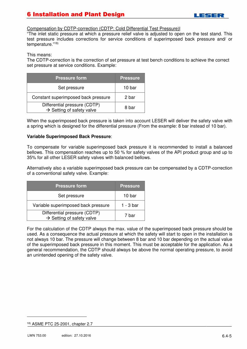
Compensation by CDTP-correction (CDTP: Cold Differential Test Pressure)l “The inlet static pressure at which a pressure relief valve is adjusted to open on the test stand. This test pressure includes corrections for service conditions of superimposed back pressure and/ or temperature.”18) This means: The CDTP-correction is the correction of set pressure at test bench conditions to achieve the correct set pressure at service conditions. Example:
Pressure form Pressure
Set pressure 10 bar
Constant superimposed back pressure 2 bar
Differential pressure (CDTP) � Setting of safety valve 8 bar
When the superimposed back pressure is taken into account LESER will deliver the safety valve with a spring which is designed for the differential pressure (From the example: 8 bar instead of 10 bar). Variable Superimposed Back Pressure: To compensate for variable superimposed back pressure it is recommended to install a balanced bellows. This compensation reaches up to 50 % for safety valves of the API product group and up to 35% for all other LESER safety valves with balanced bellows. Alternatively also a variable superimposed back pressure can be compensated by a CDTP-correction of a conventional safety valve. Example:
Pressure form Pressure
Set pressure 10 bar
Variable superimposed back pressure 1 - 3 bar
Differential pressure (CDTP) � Setting of safety valve
7 bar
For the calculation of the CDTP always the max. value of the superimposed back pressure should be used. As a consequence the actual pressure at which the safety will start to open in the installation is not always 10 bar. The pressure will change between 8 bar and 10 bar depending on the actual value of the superimposed back pressure in this moment. This must be acceptable for the application. As a general recommendation, the CDTP should always be above the normal operating pressure, to avoid an unintended opening of the safety valve.
18) ASME PTC 25-2001, chapter 2.7