650 accu-master automatic reel mower grinder - operators... · the warning symbol identifies...
TRANSCRIPT

1
This book consists of two manuals:
The OPERATORS MANUAL which contains all theinformation on operating and doing routine dailymaintenance on this equipment.
The ASSEMBLY and SERVICE MANUAL which isused by the maintainence department to install theequipment and to do all maintenance except routinedaily maintenance.
Setting the Standard With theWorld's Most Valued Grinders.
650ACCU-MasterAUTOMATIC
REEL MOWER GRINDER

2

3
ACCU-MasterAUTOMATIC
REEL MOWER GRINDER
OPERATORSMANUAL
WARNINGYou must thoroughly read and understand thismanual before operating the equipment, payingparticular attention to the Warning & Safety instructions.
6507920 (3-01)
4
SAFETY INSTRUCTIONS
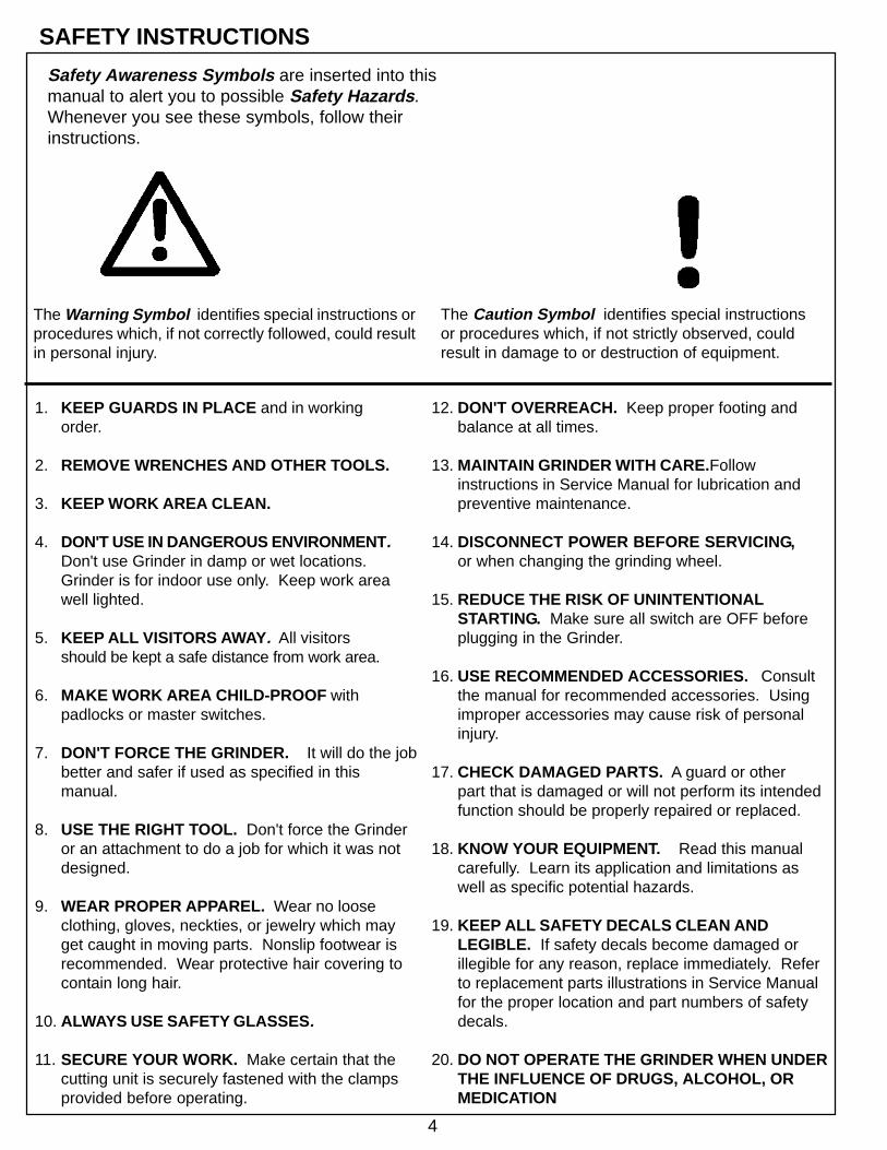
Safety Awareness Symbols are inserted into thismanual to alert you to possible Safety Hazards .Whenever you see these symbols, follow theirinstructions.
The Warning Symbol identifies special instructions orprocedures which, if not correctly followed, could resultin personal injury.
The Caution Symbol identifies special instructionsor procedures which, if not strictly observed, couldresult in damage to or destruction of equipment.
12. DON'T OVERREACH. Keep proper footing andbalance at all times.
13. MAINTAIN GRINDER WITH CARE. Followinstructions in Service Manual for lubrication andpreventive maintenance.
14. DISCONNECT POWER BEFORE SERVICING,or when changing the grinding wheel.
15. REDUCE THE RISK OF UNINTENTIONALSTARTING. Make sure all switch are OFF beforeplugging in the Grinder.
16. USE RECOMMENDED ACCESSORIES. Consultthe manual for recommended accessories. Usingimproper accessories may cause risk of personalinjury.
17. CHECK DAMAGED PARTS. A guard or otherpart that is damaged or will not perform its intendedfunction should be properly repaired or replaced.
18. KNOW YOUR EQUIPMENT. Read this manualcarefully. Learn its application and limitations aswell as specific potential hazards.
19. KEEP ALL SAFETY DECALS CLEAN ANDLEGIBLE. If safety decals become damaged orillegible for any reason, replace immediately. Referto replacement parts illustrations in Service Manualfor the proper location and part numbers of safetydecals.
20. DO NOT OPERATE THE GRINDER WHEN UNDERTHE INFLUENCE OF DRUGS, ALCOHOL, ORMEDICATION
1. KEEP GUARDS IN PLACE and in workingorder.
2. REMOVE WRENCHES AND OTHER TOOLS.
3. KEEP WORK AREA CLEAN.
4. DON'T USE IN DANGEROUS ENVIRONMENT.Don't use Grinder in damp or wet locations.Grinder is for indoor use only. Keep work areawell lighted.
5. KEEP ALL VISITORS AWAY . All visitorsshould be kept a safe distance from work area.
6. MAKE WORK AREA CHILD-PROOF withpadlocks or master switches.
7. DON'T FORCE THE GRINDER. It will do the jobbetter and safer if used as specified in thismanual.
8. USE THE RIGHT TOOL. Don't force the Grinderor an attachment to do a job for which it was notdesigned.
9. WEAR PROPER APPAREL. Wear no looseclothing, gloves, neckties, or jewelry which mayget caught in moving parts. Nonslip footwear isrecommended. Wear protective hair covering tocontain long hair.
10. ALWAYS USE SAFETY GLASSES .
11. SECURE YOUR WORK. Make certain that thecutting unit is securely fastened with the clampsprovided before operating.

5
SAFETY INSTRUCTIONS
DO1. DO always HANDLE AND STORE wheels in a
CAREFUL manner.
2. DO VISUALLY INSPECT all wheels beforemounting for possible damage.
3. DO CHECK MACHINE SPEED against theestablished maximum safe operating speedmarked on wheel.
4. DO CHECK MOUNTING FLANGES for equaland correct diameter.
5. DO USE MOUNTING BLOTTERS whensupplied with wheels.
6. DO be sure WORK REST is properly adjusted.
7. DO always USE A SAFETY GUARDCOVERING at least one-half of the grindingwheel.
8. DO allow NEWLY MOUNTED WHEELS to runat operating speed, with guard in place, for atleast one minute before grinding.
9. DO always WEAR SAFETY GLASSES or sometype of eye protection when grinding.
DON'T1. DON'T use a cracked wheel or one that HAS
BEEN DROPPED or has become damaged.
2. DON'T FORCE a wheel onto the machine ORALTER the size of the mounting hole - ifwheel won't fit the machine, get one that will.
3. DON'T ever EXCEED MAXIMUMOPERATING SPEED established for thewheel.
4. DON'T use mounting flanges on which thebearing surfaces ARE NOT CLEAN, FLATAND FREE OF BURNS.
5. DON'T TIGHTEN the mounting nutEXCESSIVELY.
6. DON'T grind on the SIDE OF THE WHEEL(see Safety Code B7.2 for exception).
7. DON'T start the machine until the WHEELGUARD IS IN PLACE.
8. DON'T JAM work into the wheel.
9. DON'T STAND DIRECTLY IN FRONT of agrinding wheel whenever a grinder is started.
10. DON'T FORCE GRINDING so that motorslows noticeably or work gets hot.
AVOID INHALATION OF DUST generated by grinding and cutting operations.Exposure to dust may cause respiratory ailments. Use approved NIOSH orMSHA respirators, safety glasses or face shields, and protective clothing.Provide adequate ventilation to eliminate dust, or to maintain dust levelbelow the Threshold Limit Value for nuisance dust as classified by OSHA.
IMPROPER USE OF GRINDING WHEEL MAY CAUSEBREAKAGE AND SERIOUS INJURY.
Grinding is a safe operation if the few basic rules listed below are followed.These rules are based on material contained in the ANSI B7.1 Safety Code for"Use, Care and Protection of Abrasive Wheels". For your safety, we suggestyou benefit from the experience of others and carefully follow these rules.

6
W e are committed to:
Providing superior customer support, training,and service.
Manufacturing the highest quality products at anunequaled value.
Setting the industry standard by investing intechnological product innovation.
Manufacturing products specifically designed tomaintain original equipment manufacturers'specifications.
Interacting with and supporting all originalequipment manufacturers.
Setting the Standard With the World's Most Valued Grinders.
7
This machine is intended for grinding the reel of reel type mower units ONLY.Any use other than this may cause personal injury and void the warranty.
To assure the quality and safety of your machine and to maintain thewarranty, you MUST use original equipment manufactures replacementparts and have any repair work done by a qualified professional.
ALL operators of this equipment must be thoroughly trained BEFOREoperating the equipment.
Do not use compressed air to clean grinding dust from the machine. Thisdust can cause personal injury as well as damage to the grinder. Machine is forindoor use only. Do not powerwash machine.
TABLE OF CONTENTS
CONTENTS
Safety Warnings ...................................................................................................... Page 4-6Daily Maintenance................................................................................................... Page 6Getting to Know Your Grinder .................................................................................. Page 7-15Safety Warnings ...................................................................................................... Page 16-18Winch Safety and Instructions .................................................................................. Page 20-21Operating Instructions .............................................................................................. Page 22-36Reel Setup Chart ..................................................................................................... Page 37
DAILY MAINTENANCE BY THE OPERATOR
On a daily basis, clean the machine by wiping it off, and cleaning it using the built-in vacuum.On a daily basis, remove all grinding grit from the grinding head and bellows area.On a daily basis, inspect the machine for loose fasteners or components.Contact your company's Maintenance Department if damaged or defective parts are found.
DO NOT USE COMPRESSED AIR TOCLEAN GRINDING DUST FROM GRINDER.
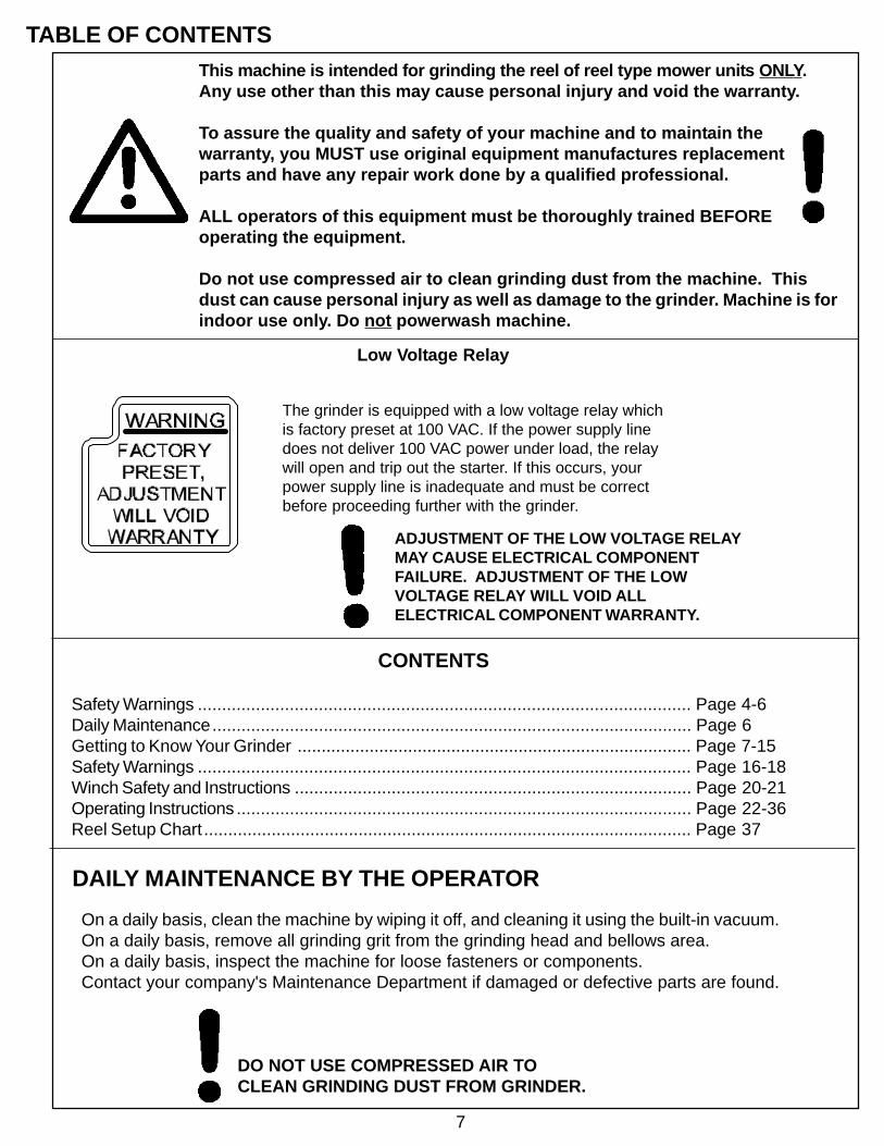
The grinder is equipped with a low voltage relay whichis factory preset at 100 VAC. If the power supply linedoes not deliver 100 VAC power under load, the relaywill open and trip out the starter. If this occurs, yourpower supply line is inadequate and must be correctbefore proceeding further with the grinder.
ADJUSTMENT OF THE LOW VOLTAGE RELAYMAY CAUSE ELECTRICAL COMPONENTFAILURE. ADJUSTMENT OF THE LOWVOLTAGE RELAY WILL VOID ALLELECTRICAL COMPONENT WARRANTY.
Low Voltage Relay

8
SPECIFICATIONS
Traversing Switches Solid state, non-contacting proximity switches.Carriage Travel 38" [97 cm]Overall Width 71" closed [181 cm]Overall Height 87" [221 cm]Overall Depth 61" [155 cm]Weight 2300 lbs. [1045 kg] 2500 lbs shipping weight [1140 kg]Base Construction Precision heavy duty reinforced welded steel baseCarriage Rails Precision Ground, Hardened Steel - 1.000 Dia. [25.4 mm]Grind Head Motor 1 HP DC Motor, 4300 RPMWinch Capacity 400 lbs. maximum [180 kg]Spin Motor .20 HP Fan Cooled Variable Speed DC MotorAuto Traverse Ball bearing threadless roller drive with built-in overload protectionRail Covers Telescoping bellowsControl System Safety power and main door interrupt switches
• Fully automatic cycle for Spin or Relief Grind. • Permanent Memory stored programs on an E-Prom.• Reversible Spin drive for Spin or Relief Functions • 10 selectable grind program input thumbwheel with 5 with manual (jog) functions for machine setup. spin grind and 5 relief grind programs.• Relief Blade count input thumbwheel. • End of Cycle flashing light.• Solid state two speed manual (jog) infeed Panel digital display for error, diagnostic or prompt stepper functions. messages.• Solid State program logic controller with • Solid State variable spin speed control, variable 16 inputs and 6 outputs. speed traverse control and grinding motor control.
GETTING TO KNOW YOUR GRINDER
l
Sound Level Less than 75 Dba
9
CONTROL PANEL COMPONENT IDENTIFICATIONReview the following control panel component descriptions before proceeding with the instructions.
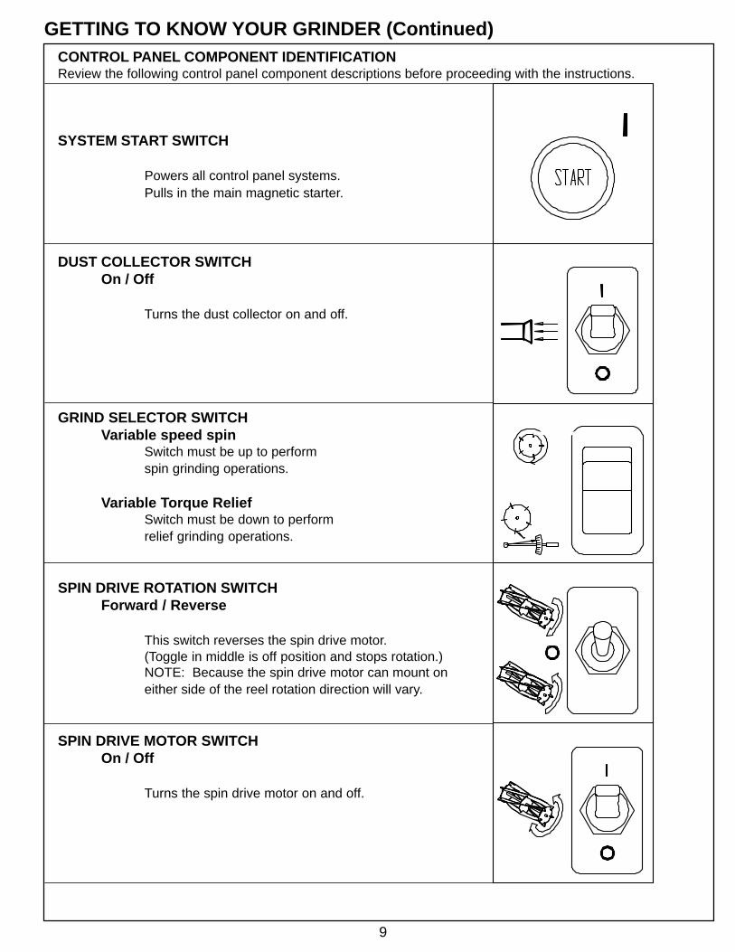
SYSTEM START SWITCH
Powers all control panel systems.Pulls in the main magnetic starter.
DUST COLLECTOR SWITCHOn / Off
Turns the dust collector on and off.
GRIND SELECTOR SWITCHVariable speed spin
Switch must be up to performspin grinding operations.
Variable Torque ReliefSwitch must be down to performrelief grinding operations.
SPIN DRIVE ROTATION SWITCHForward / Reverse
This switch reverses the spin drive motor.(Toggle in middle is off position and stops rotation.)NOTE: Because the spin drive motor can mount oneither side of the reel rotation direction will vary.
SPIN DRIVE MOTOR SWITCHOn / Off
Turns the spin drive motor on and off.
GETTING TO KNOW YOUR GRINDER (Continued)

10
GETTING TO KNOW YOUR GRINDER (Continued)
SPIN SPEED DIALRPM
Adjusts the speed of reel rotation whenyou have the grind selector switchset at variable speed spin.
PROGRAM NO. INDICATORSelects automatic program number for both spingrinding (1-5) and relief grinding (6-0).
RELIEF BLADE NO. INDICATORSets the number of blades on the reel forrelief grinding only (4-11).
PROGRAM START SWITCH
Push this button to start grinding in anautomatic program sequence.
RELIEF TORQUE DIAL
Adjusts the Spin Drive Motor torque (thetorque holding the reel blade to the relief finger)when Grind Selector Switch is set at variableTorque Relief.

11
GETTING TO KNOW YOUR GRINDER (Continued)
GRINDING WHEEL MOTOR SWITCHOn / Off
Turns the Grinding Wheel Motor on and off.
NOTE: Grinding wheel motor will not function with the doors open.
AUTO / MANUAL SELECTOR SWITCHAuto Program
Switch must be up to start automaticprogram sequence.
Manual JogSwitch must be down to use Infeed JogSelector Switch & Traverse Jog SelectorSwitch during setup.
INFEED JOG SELECTORSlow/Fast
Switch up is fast infeed speed & switch down is slowinfeed speed. Each bump of the AC Stepper Motorequals .0005" [.013 mm] movement. On slow theinfeed moves 2 bumps or .001" [.03 mm] per second.On fast the infeed moves 34 bumps or .017" [.4 mm]per second.
INFEED JOG SELECTORUp / Down
Moves the Grinding Wheel up or down.(Auto/Manual Selector Switch must be set at Manual Jog).
TRAVERSE JOG SELECTORReset
Resets Traverse Movement if safetyoverload switch trips. NOTE: Red lightshows when overload has been tripped.
12
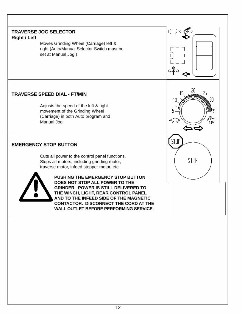
TRAVERSE JOG SELECTORRight / Left
Moves Grinding Wheel (Carriage) left &right (Auto/Manual Selector Switch must beset at Manual Jog.)
TRAVERSE SPEED DIAL - FT/MIN
Adjusts the speed of the left & rightmovement of the Grinding Wheel(Carriage) in both Auto program andManual Jog.
EMERGENCY STOP BUTTON
Cuts all power to the control panel functions.Stops all motors, including grinding motor,traverse motor, infeed stepper motor, etc.
PUSHING THE EMERGENCY STOP BUTTONDOES NOT STOP ALL POWER TO THEGRINDER. POWER IS STILL DELIVERED TOTHE WINCH, LIGHT, REAR CONTROL PANELAND TO THE INFEED SIDE OF THE MAGNETICCONTACTOR. DISCONNECT THE CORD AT THEWALL OUTLET BEFORE PERFORMING SERVICE.

13
FRONT AND REAR MOWER MOUNTINGThe mowing unit is placed into the machine with the rearroller on the table and front roller held with the front toolingclamps. The front tooling clamps can be moved from sideto side along the tooling bar so they can be positioned asfar apart as possible on varying widths of reels (loosen knobon lower part of bar mounting bracket in FIG.1). You alsohave the ability to adjust the height (loosen knob on horizontalbracket in FIG.1) and the forward and backward position(loosen knob on roller clamp bracket in FIG1). This allowsthe mower unit to be set up with the bottom of the reelapproximately flush to the table and the center of the reelaligned to the reel positioner gage (see section on reelpositioner gage below). When the front tooling clamps andmower unit are in proper position lock in place by tighteningknobs. The rear roller clamp is positioned with the V-clampblock centered on the rear roller. The height of the rearroller clamp can be adjusted down by simply pushing theunit down and adjusted up by first pulling up on the ponyleafs and then sliding the unit up. To lock the front toolingclamps rotate the roller clamp up and lock in place with thequick release pin. Then turn the t-knobs clockwise untilroller is firmly held in place. See FIG. 1.
REEL POSITIONER GAGEThe Reel Positioner Gage is used to obtain proper in andout (fore and aft) positioning of the mower unit. Mount theReel Positioner Gage onto the table with the ears buttedagainst gaging surface of the table. See FIG. 2. You thenposition the center of the reel within the slot in the PositionerGage. This is an approximate starting point for setuppurposes. There are special reels and unique situationsthat may require the reel to not be set on the center of theflag. This flag is for setup reference only.
TRAVERSE ACTUATOR RELEASEThe actuator that drives the grinding carriage left and rightcan be released to allow manual movement of the grindingcarriage. The actuator release arm is located at the front ofthe carriage under the Carriage Proximity Flag Bracket.See FIG. 3. Rotate the release arm clockwise approximately1/2 turn to release actuator and counter clockwise approximately1/2 turn to engage actuator.
GRINDING HEAD POSITIONS SPIN/RELIEFThe Finger and Body Assembly of the grinding head ro-tates on the Grinding Head Housing to change positionsbetween spin grinding and relief grinding. To change theposition of the Finger and Body Assembly you have to pullout the Plunger Pin on the left side of the Grinding HeadHousing. See FIG. 5. When you are going to perform spingrinding operations the Finger and Body Assembly must berotated clockwise (looking at it from the right). This rotatesthe fingers out of the reel blade path. See FIG. 5. Whenyou are going to perform relief grinding operations the Fin-ger and Body Assembly must be rotated counter clockwise.This rotates the finger into position to touch and control thereel blades. Because the Plunger Pin engages into the Ad-justable Relief Adjuster and it sometimes will not fullyengage, make certain it is fully engaged. See FIG. 6.
FIG. 1
FIG. 3
FIG. 2
GETTING TO KNOW YOUR GRINDER (Continued)

14
GETTING TO KNOW YOUR GRINDER (Continued)
FIG. 5
FIG. 4
Detail shows Finger and Body Assembly rotated(clockwise) into the spin grinding position(shown without grinding wheel for clarity).
Plunger Pin
Index StopFinger
Fixed ReliefFinger
Grinding Head Housing Finger & Body Assembly
Traverse Left LimitProximity Sensor
Traverse Right LimitProximity Sensor
Traverse Base standing alonewithout dust protection components.
TRAVERSE PROXIMITY SENSORSThe Traverse Proximity Sensors are used to change thetraversing directions for the grinding carriage and aremounted in the Proximity Brackets located in front of theTraverse Base. See FIG. 4. The sensors are mountedwith wave washers to allow a left and right sliding move-ment without loosening the sensor nuts. There is a redlight on the sensor which lights up when the switch isactivated.
FIG. 5. The Fixed Relief Finger is equivalent to the ReliefFingers on other relief grinders. When relief grinding theMovable Index Stop Finger moves from the Relief Finger Side(back side) of the reel blade when traversing from right to leftto the grinding wheel side (front side) of the reel blade whentraversing from left to right. This feature allows the fully Auto-matic Relief function. When performing relief grinding op-erations it is important to have the Index Stop Finger adjustedproperly.
STEP 1: Once you have the Grinding Head positioned with areel blade resting on the Fixed Relief Finger high point, youwant about 1/32" [.8 mm) to 1/16" [1.5 mm] free play of theIndex Finger behind the reel blade. The Index Finger is springloaded to the up position. To check free play, push down onthe Index Finger. See FIG. 6. To make this adjustment youhave to first turn the Index Lock Handle counter clockwise tounlock the adjustable Index Lever. See FIG. 6. If there is nofree play of the Index Finger you want to rotate the Adjust-able Index Lever clockwise. If there is more than 1/16" [1.5mm] free play you want to rotate the Adjustable Index Levercounter clockwise. When the Index Finger is in proper posi-tion rotate the Index Lock Handle clockwise to lock the Ad-justable Index Lever.The Index Stop Pin is height adjustable. It should be ad-justed to catch the reel blade and still leave enough clear-ance to the reel spider after the relief is ground to the depthrequired.
NOTE: The reason for the 1/32" (1 mm) clearance is so thatthe high point of the Relief Finger is acting as the guide dur-ing the relief grind cycle. The Index Stop Finger acts as aguide onto the tapered ramp of the Relief Finger.

15
STEP 2: With the down limit of the Index Finger properly setyou may have to adjust the up limit of the Index Finger for 5"(127 mm) diameter reels with reverse helix blades.The up travel limit is restricted to keep the Index Finger inthe reel blade index path. This is done to properly catch thenext blade when indexing or to allow clearance between theback side of the Index Finger and the front side of the bladewhen the grinding carriage is making its return trip to thehome position.If the Index Finger has problems catching the next bladeturn the Index Finger T-knob counterclockwise. If there isn’tenough clearance between the back side of the Index Fin-ger and the front side of the reel blade turn the Index FingerT-knob clockwise. See FIG. 6.Adjust the T-knob in by 1/8" (3 mm) into the hole opening sothe up travel is restricted. Check the up and down swing ofthe Index Finger for clearance on both sides of the reel bladefor the relief grind.
GETTING TO KNOW YOUR GRINDER (Continued)
NOTE: This adjustment is factory set for maximum up travelof the index finger for 1/4" (6 mm) reel blade thickness. Thisadjustment should only be needed for small diameter reels,such as 5" [127 mm] diameter reels with reverse helix blades.This adjustment is functional only on cutting units with thinblades on small reels.
ALIGNMENT GAGE
A properly grounded reel should be cylindrical. all taper mustbe ground out of the reel. To ensure te reel will be groundcorrectly it MUST be aligned precisely prior to grinding. Thedigital alignment gage is used for accurate reel setup. Thesame gage is used for setting both the horizontal and verti-cal alignment within thousands of an inch. The digital gageallows you to measure one end of the reel by extending theslide rail until you make contact with center hub of the reel byextending the slide rail until you make contact with the cen-ter hub of the reel. See FIG> 7. You then reset the gage tozero, retract the slide rail and measure the other end of thereel. The reading on the digital scale tells you exactly how farout of alignment you are. NOTE: Gage can be set for bothinch and metric readout.
DUST COLLECTORThe dust collector unit is used during grinding operations tocollect the majority of the grinding dust directly under the grind-ing wheel. Since the dust collector unit is actually and indus-trial vacuum you can disconnect the vacuum hose from thecarriage base and use the vacuum to clean the entire ma-chine. See FIG. 8.
FIG. 8
FIG. 7
FIG. 6
AdjustableIndex LeverIndex FingerT-KnobIndex FingerProximity Sensor
Index FingerLocking Pin inRetracted Position
Detail shows Finger and Bed Assemblyrotated counterclockwise into reliefgrinding position (shown withoutgrinding wheel for clarity).
Push Index Finger hereto check for free play.
Index LockHandle
Reel Center Shaft
ON\OFF
IN\MM
Indicator Slide Rail
Zero Reset
NEVER USE COMPRESSED AIR TO CLEANANY AREA OF THE MACHINE.

16
GETTING TO KNOW YOUR GRINDER (Continued)
MACHINE SERVICE LIGHTThe machine service light is mounted under the rightside proximity bracket and the switch is located to thefront of the machine base on the right side panel.The service light is independent of grinding operationso it can be on or off at any time. See FIG. 10.
NOTE:There is also a light switch on the back of the light unit.
RELIEF ANGLE ADJUSTMENTYou should always make sure the Reel Positioner Adjuster isat its mid point before you set up a reel to grind. This willallow to adjust the relief angle by approximately 8 degrees inboth directions. You can find the mid point by turning theReel Positioner Adjuster clockwise, using the 5/16" Allen Keyincluded with the grinder, until it makes contact with the stoppin. Then turn the Reel Positioner Adjuster counterclock-wise until it makes contact with the stop plate counting thenumber of revolutions. Now turn the Reel Positioner Adjusterclockwise again 1/2 the number of revolutions you counted.
As an example, if the angle you obtain from initial set up is30 degrees, you can increase the angle as far as approxi-mately 38 degrees by rotating the Reel Positioner Adjusterclockwise until it makes contact with the stop pin. (NOTE: If38 degrees is not enough relief angle you can move the reelforward one notch on the front tooling horizontal bracket.Make sure you reset the Reel Positioner Adjuster to the midpoint again before you move the reel, and always realign reelif it is moved. You can decrease the angle as far as approxi-mately 22 degrees by rotating the Reel Positioner Adjustercounterclockwise until it make contact with the stop plate.(NOTE: If 22 degrees is still to much relief angle, you canmove the reel back one notch on the front tooling horizontalbracket.)
FIG. 10
FIG. 10A

17
WARNINGTHIS GRINDER OPERATES WITH A LARGE AMOUNT OF HOT SPARKS,WHEN GRINDING A UNIT WITH A FUEL TANK, MAKE CERTAIN THEREIS NO EXPOSED FUEL AND THAT THE GAS CAP IS TIGHT AND THEVENT TAPED SHUT. CLOSE DOORS AND LATCH PRIOR TO GRINDINGIN AUTO PROGRAM OR MANUAL JOG CYCLE.
WARNING
WINCH IS FOR LIFTING CUTTING UNITS ONLY. DO NOT USE FOR ANY OTHER PURPOSE.
ALWAYS HAVE LIFTING HOOKS SECURELY ATTACHED AND BALANCED BEFORE LIFTING.
STAND WELL CLEAR OF THE CUTTING UNIT WHEN LIFTING. GUIDE THE CUTTING UNITWITH EXTENDED ARMS ONLY.
WINCH CAPACITY IS 400 LBS. MAXIMUM.
READ THE WARNINGS IN THE WINCH SECTION OF THE ASSEMBLY AND OPERATINGMANUAL BEFORE USING THE WINCH.
SAFETY INSTRUCTIONS
Safety Awareness Symbols are inserted in this manualto alert you to possible Safety Hazards. Whenever yousee these symbols, heed their instructions.
The Caution Symbol identifies specialinstructions or procedures which, if notstrictly observed, could result in damageto, or destruction of equipment.
The Warning Symbol identifies special instructionsor procedures which, if not correctly followed, couldresult in personal injury.
PLEASE TAKE SPECIAL NOTE OF THE FOLLOWING WARNINGDECALS LOCATED ON THE FRONT OF THE GRINDER, THEWINCH BOOM AND THE FRONT TOOLING BAR OF THE ACCU-Master.

18
WARNING
FOR YOUR OWN SAFETY READ ASSEMBLY ANDOPERATING MANUAL BEFORE OPERATING
1. ALWAYS USE SAFETY GLASSES.
2. DO NOT WEAR GLOVES, NECKTIES, LOOSE CLOTHING, ETC.
3. THIS MACHINE OPERATES WITH A LARGE AMOUNT OF HOTSPARKS, WHEN GRINDING A UNIT WITH A FUEL TANK, MAKECERTAIN THERE IS NO EXPOSED FUEL AND THAT THE GASCAP IS TIGHT WITH THE VENT TAPED SHUT.
4. STAY CLEAR OF GRINDING WHEEL CONTACT AREA WHEN INMANUAL JOG CYCLE. ALWAYS STAY CLEAR OF ALL ROTATINGAND MOVING PARTS WHEN IN MANUAL JOG CYCLE.
5. ONLY PROPERLY TRAINED PERSONNEL SHOULD OPERATETHE MACHINE. KEEP ALL VISITORS A SAFE DISTANCE FROMTHE MACHINE WHEN IN MANUAL JOG CYCLE.
6. BE CERTAIN THAT THE CUTTING UNIT IS SECURELY FASTENEDWITH THE CLAMPS PROVIDED BEFORE OPERATING.
7. DO NOT EXCEED MAXIMUM OPERATING SPEED MARKED ONTHE GRINDING WHEEL. (READ GRINDING WHEEL SAFETYSECTION IN YOUR MANUAL BEFORE GRINDING).
8. DISCONNECT YOUR MACHINE FROM THE MAIN POWER SOURCEBEFORE PERFORMING ANY MECHANICAL OR ELECTRICAL SERVICING.
9. KEEP ALL GUARDS IN PLACE AND IN GOOD REPAIR.
10. BEFORE OPERATING INSPECT THE MACHINE FOR LOOSE,DAMAGED OR MISSING PARTS. IF FOUND, REPAIR OR REPLACE.REMOVE ALL TOOLS FROM OPERATING AREA.
11. CLOSE DOORS AND LATCH PRIOR TO GRINDING IN AUTOPROGRAM OR MANUAL JOG CYCLE.
--SEE MANUAL FOR PROPER GRINDING INSTRUCTIONS--
SAFETY INSTRUCTIONS CONT.

19
OPERATING INSTRUCTIONS
Symbol to keep exposedgasoline or flammablesaway from the grinderbecause it operates with alarge amount of sparks.
Symbol for maximum weightcapacity for winch.
Symbol identifying a panel,cover, or area as having liveelectrical components within.
Symbol for caution relatingto RPM of the motor andminimum safe rated RPM ofthe grinding wheel.
Symbol to keep visitorsa safe distance awayfrom the grinder.
Symbol for sharp object whichwill cause serious injury.
Symbols for Readoperators manual, wear safetyglasses anddisconnect power beforeservicing.

20
--This page left intentionally blank for note taking purposes--

21
Read carefully before attempting to operate or service your winch! Failure to complywith instructions could result in personal injury and/or property damage!
FOR YOUR OWN SAFETY AND THAT OF OTHERS, THIS EQUIPMENT MUST BE USEDAS RECOMMENDED BY THE MANUFACTURER. FAILURE TO HEED THE FOLLOWINGRECOMMENDATIONS COULD ENDANGER YOUR LIFE.
WINCH OPERATING INSTRUCTIONS
1. Maximum pulling capacity is 400 pounds (180 kg.)in single line operation. DO NOT ATTEMPT TO MOVELOADS GREATER THAN THESE RATINGS.
2. NEVER CARRY personnel on the hook or the load.
3. NEVER MOVE A LOAD with this winch until allpersonnel are clear.
4. NEVER HOOK THE WIRE ROPE BACK ONITSELF. USE THE SPREADER BAR ASSEMBLY.Hooking the wire rope back on itself creates anunacceptable strain on the wire rope.
5. DO NOT ALLOW unqualified personnel to operatethis unit.
6. KEEP CLEAR OF WINCH WIRE ROPE AND HOOKWHEN OPERATING WINCH. DO NOT ATTEMPTto guide wire rope by hand as it rewinds.
7. DO NOT use the wire rope as a ground for welding.
8. NEVER TOUCH a welding electrode to the wire rope.
9. WHEN SPREADER BAR ASSEMBLY IS USED be sureit is properly seated in the saddle of the hook.
10. AVOID excessive inching and quick reversals of load.
11. BE SURE that the power supply is disconnectedbefore performing maintenance and repair procedure.
12. DO NOT OPERATE this unit if it is not functioningproperly.
13. MAINTAIN A MINIMUM OF 4 TURNS OF WIREROPE around the winch drum to prevent thewire rope from pulling off under load.
14. KEEP WINCHING AREA CLEAR . Do notallow people to remain in the winching area.Do not stand between the winch and load.
15. INSPECT WIRE ROPE FREQUENTLY. Afrayed wire rope with broken strands should bereplaced immediately. Never replace the wire rope withrope of any kind or with wire rope other than the typeand size specified in the repair parts section of thismanual.
16. USE HEAVY LEATHER GLOVES whenhandling the wire rope to eliminate the possibilityof cuts or scratches from burrs and slivers frombroken strands.
17. ALLOW WINCH TO COOL DOWNFREQUENTLY, as the motor is designed forintermittent duty only. When the metal motorhousing is hot to touch, it is time to let the winchcool down
18. DO NOT OPERATE WINCH WHEN UNDERTHE INFLUENCE OF DRUGS, ALCOHOL, ORMEDICATION.
19. DO NOT USE WINCH TO HOLD LOADS INPLACE . Use other means of securing loads,such as tie down straps.
20. USE ONLY FACTORY APPROVED SWITCHES,REMOTE CONTROLS AND ACCESSORIES .Use of non-factory approved components may causeinjury or property damage and could void your warranty.
21. DO NOT MACHINE OR WELD ANY PART OFTHE WINCH. Such alterations may weakenthe structural integrity of the winch and couldvoid your warranty.
22. DO NOT OPERATE THIS WINCH OUTDOORS OR IN A CORROSIVE OREXPLOSIVE ENVIRONMENT.

22
This unit is activated via the switch at the end of the onefoot cord. To remove wire rope from the winch, depress the"CABLE OUT" button. The load will stop without coastingwhen the button is released. To pull a load or spool wirerope onto the drum, depress the "CABLE IN" button.
This winch is designed to pull 400 lbs (180 KG) in singleline for 20 seconds "on" time on the wire rope layer closestto the drum. Attempts to pull more than this weight orexceed the duty cycle may cause damage to the winch orwire rope and could cause the circuit breaker to trip, andthe winch will not operate. (See "Trouble Shooting" sectionfor instruction on resetting the circuit breaker.) Maintaina minimum of four wraps of wire rope around the winchdrum before attempting any pulls.
DO NOT put angular loads onthe winch. Whenever possible,pull should always beperpendicular to winch.
Keep wire rope tight and even onspool.
Replace wire rope when frayed.
Keep wire rope under tension whenoperating winch. Wire rope will"stack up" loosely on spool if notkept under tension.
A part of your winch that will require periodicattention and eventual replacement is the wire rope.Inspect the wire rope frequently. If fraying exists,replace the wire rope at once. Your winch usesgalvanized aircraft type 1/8" DIA. [3 mm] 7 x 19 cable.Always replace the wire rope with the replacement ropespecified in the parts section of this manual. Because allrope is subject to wear, it is excluded from our warranty.
LUBRICATIONYour new winch has lifetime lubrication. There may be greaseleakage out of the winch, especially during the first fewoperations, this is normal. It is not necessary to grease or oilany part of the winch at any time. If grease leakage continuesbeyond a short period of time, the winch should be inspectedfor cause. See the Assembly and Service Manual.
WINCH OPERATING INSTRUCTIONS (Continued)TROUBLESHOOTINGIf the Superwinch fails to operate, the circuitbreaker on the end of the Superwinch motorshould be checked. If the circuit breaker hastripped, this will be indicated by the centerportion of the breaker protruding from themain body. To reset the breaker, merelypress the center portion back into the assembly.
NOTE: Repeated tripping of the breakerindicates an overload condition which shouldbe eliminated immediately to insuremaximum life from your winch.
23
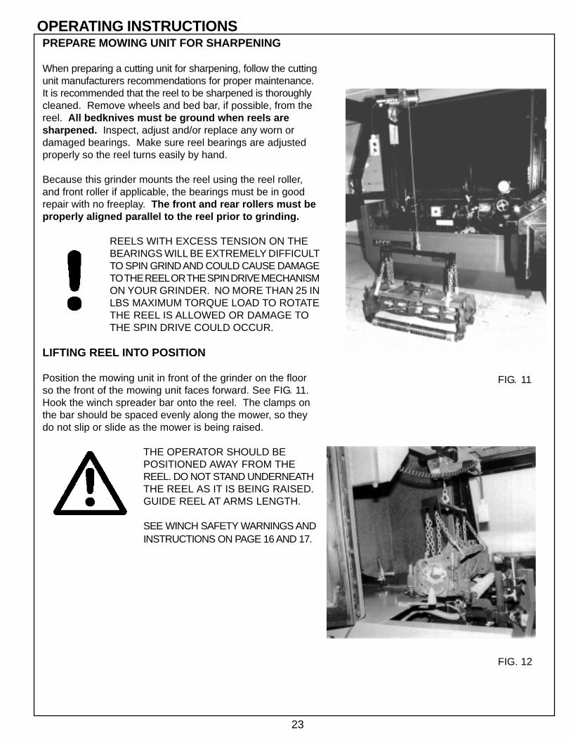
PREPARE MOWING UNIT FOR SHARPENING
When preparing a cutting unit for sharpening, follow the cuttingunit manufacturers recommendations for proper maintenance.It is recommended that the reel to be sharpened is thoroughlycleaned. Remove wheels and bed bar, if possible, from thereel. All bedknives must be ground when reels aresharpened. Inspect, adjust and/or replace any worn ordamaged bearings. Make sure reel bearings are adjustedproperly so the reel turns easily by hand.
Because this grinder mounts the reel using the reel roller,and front roller if applicable, the bearings must be in goodrepair with no freeplay. The front and rear rollers must beproperly aligned parallel to the reel prior to grinding.
REELS WITH EXCESS TENSION ON THEBEARINGS WILL BE EXTREMELY DIFFICULTTO SPIN GRIND AND COULD CAUSE DAMAGETO THE REEL OR THE SPIN DRIVE MECHANISMON YOUR GRINDER. NO MORE THAN 25 INLBS MAXIMUM TORQUE LOAD TO ROTATETHE REEL IS ALLOWED OR DAMAGE TOTHE SPIN DRIVE COULD OCCUR.
LIFTING REEL INTO POSITION
Position the mowing unit in front of the grinder on the floorso the front of the mowing unit faces forward. See FIG. 11.Hook the winch spreader bar onto the reel. The clamps onthe bar should be spaced evenly along the mower, so theydo not slip or slide as the mower is being raised.
THE OPERATOR SHOULD BEPOSITIONED AWAY FROM THEREEL. DO NOT STAND UNDERNEATHTHE REEL AS IT IS BEING RAISED.GUIDE REEL AT ARMS LENGTH.
SEE WINCH SAFETY WARNINGS ANDINSTRUCTIONS ON PAGE 16 AND 17.
OPERATING INSTRUCTIONS
FIG. 12
FIG. 11

24
INSTALL REELUse the winch to lift the reel to the approximate position,having the rear roller on the table top, and front roller onfront roller clamps. See FIG. 12.
MAKE SURE GRINDING WHEEL IS LOWENOUGH TO CLEAR THE REEL. YOU CANLOWER THE GRINDING WHEEL BYSETTING THE AUTO/MANUAL SELECTORTO MANUAL JOG AND DEPRESSING THEINFEED JOG BUTTON DOWN.
Position front roller clamps as far out as possible to the endsof the front roller, and center on the machine. See FIG. 12
Set the vertical height of the front clamps so the reel bottomis flush to 3/8" [10 mm] above the table surface. See FIG. 13.
Set the fore and aft position of the front clamps with the reelPositioning Gage. Place the reel positioner gage againstgaging surface. See FIG. 14. You want to align the center ofthe reel within the slot of the positioner gage.
THE HORIZONTAL SCALES AND VERTICALTOOLING SCALES MUST MATCH FORPROPER ALIGNMENT.
For greensmower reels, the 4" [102 mm] diameter grindingwheel must clear the front roller V-bracket by approximately1/4" [6 mm]. REFER TO PAGE 35 FOR SETUP CHART.
Make certain the reel is parallel to the front edge of the table.Lock down with front clamps and rear clamp. See FIG. 15 &16.
FIRMLY TIGHTEN ALL LOCKINGKNOBS BEFORE GRINDING. ANYLOOSENESS WILL ADVERSELYAFFECT GRINDING QUALITY.
OPERATING INSTRUCTIONS (Continued)
FIG. 15
FIG. 13
FIG. 14
FIG. 16
Table Gaging Surface
Align Reel Centerwithin positionergage slot
Reel Center Line
Set bottom ofreel flush to3/8" abovetable top

25
OPERATING INSTRUCTIONS (Continued)
FIG. 18
ALIGN THE REEL
Note: When measuring to the reel center shaft always makesure you are contacting an area free of dirt and grass.
Install the horizontal extension bracket onto the carriage frontdowel pin and lock in place with knob. See FIG. 17.
Install the digital alignment gage onto the horizontalextension bracket pointing at the center of the reel shaft andlock into place with knob. See FIG. 18.
NOTE: The horizontal extension bracket is vertically adjustableso the digital gage can be positioned to avoid reel frame members,etc. The mounting of the vertical slide to the horizontalweldment has two additional mounting holes so the verticalslide can be tipped forward or back, again to avoid reel framemembers, etc. See FIG. 17.
Loosen the two locking handles on the pivot assembly on theright side of the traverse base, so that it can be adjusted inboth the vertical and horizontal plane. See FIG. 19.
First, measure the left side of the reel as far to the left as possiblewith the digital alignment gages, making sure the tip of thegage is centered on the reel center shaft. Set the gage tozero, then measure the right side at the same distance fromreel centerline as the left side. Do not rotate the reel shaftexcept for a minimum amount to clear the gage when takingmeasurements. Adjust the horizontal handwheel See FIG. 19.Repeat until alignment is within .002" [.05 mm]. Lock thehorizontal locking handle when done.
Remove the gage.
Remove the horizontal extension bracket and store iton the mount inside the canopy.
Install the digital alignment gage vertically on thecarriage front dowel pin and pointing at the center ofthe reel shaft. Lock into placewith knob. See FIG. 20 & 22.
First, measure the left side of thereel as far to the left as possible,set the gage to zero, then measurethe right side, at the same distancefrom reel centerline as the left side.See FIG. 21. Do not rotate the reelshaft except for a minimumamount to clear the gage whentaking measurements. Adjust thevertical handwheel. See FIG. 19.Repeat until alignment is within.002" [.05 mm]. Lock the verticallocking handle when done.
FIG. 21 FIG. 20
FIG. 17
FIG. 19
Horizontal Locking Handle
Traverse Base standingalone without dustprotection components
Vertical Handwheel
HorizontalHandwheel
Vertical Locking Handle
26
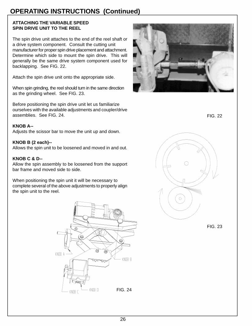
ATTACHING THE VARIABLE SPEEDSPIN DRIVE UNIT TO THE REEL
The spin drive unit attaches to the end of the reel shaft ora drive system component. Consult the cutting unitmanufacturer for proper spin drive placement and attachment.Determine which side to mount the spin drive. This willgenerally be the same drive system component used forbacklapping. See FIG. 22.
Attach the spin drive unit onto the appropriate side.
When spin grinding, the reel should turn in the same directionas the grinding wheel. See FIG. 23.
Before positioning the spin drive unit let us familiarizeourselves with the available adjustments and coupler/driveassemblies. See FIG. 24.
KNOB A--Adjusts the scissor bar to move the unit up and down.
KNOB B (2 each)--Allows the spin unit to be loosened and moved in and out.
KNOB C & D--Allow the spin assembly to be loosened from the supportbar frame and moved side to side.
When positioning the spin unit it will be necessary tocomplete several of the above adjustments to properly alignthe spin unit to the reel.
OPERATING INSTRUCTIONS (Continued)
FIG. 24
FIG. 22
FIG. 23

27
The coupler/drive assembly includes:RUBBER SLEEVE COUPLER: This is placed in thecorresponding flange coupler already mounted in the spindrive shaft. See FIG. 25.DRIVE COUPLER ADAPTER ASSEMBLY: This ismounted to the rubber coupler.ADAPTER SLEEVE: Connects the rubber coupler tothe square drive adapter.SQUARE DRIVE ADAPTER: This is inserted into thedrive coupler adapter and should be able to be movedapproximately 2" [51 mm]. It will be necessary to move thiswhen attaching reel to spin drive unit. It is then insertedinto any 1/2" square drive socket. This square shaft hasa groove machined into it on the opposite end of the snapring. This groove is there to advise that you have reachedthe maximum extension of the square drive shaft. If youcannot connect the reel without extending past this groove, thenthe spin unit must be repositioned on the tooling bar (knobs C & D).
NOTE: The 1/2" square drive socket that is placed on the reel when spingrinding is NOT included with the grinder. You must purchase this from theappropriate local supplier of tools. Some mowing units do not have a hex touse for driving with a socket. Several adapters are available from the grindermanufacturer. Additionally, you will have to make custom adapters forsome mowing units.
DO NOT EXTEND SQUARE SHAFTPAST GROOVE, INSTEADREPOSITION SPIN UNIT.
The following procedures will make setting up the spin drive unit easier.
1. Move spin drive unit close to the reel. Align the shaft on the spin drivewith the nut on reel by completing the necessary adjustments discussedon the previous page.
2. Now slide the spin drive unit approximately 7" [18 cm] from the reel drivecoupling point and securely fasten to the square mounting bar tighteningboth locking knobs. (Knobs C & D)
3. Place the proper 1/2" square drive socket or adapter on the reel drive nutand then insert the square drive shaft into the socket. Place the adaptersleeve over the drive shaft and insert the drive coupler adapter assemblyinto it. Finally place the rubber coupler onto the drive coupler adapter.See FIG. 22.
4. By holding the square drive shaft firmly into position with your left handyou will be able to move the other components to the right and insert therubber coupler into the flange on the spin drive unit. When this is donetighten the T-Knob on the adapter sleeve to hold all parts in place.
5. Finally readjust the spin drive unit if it is not in alignment.
NOTE: It is not necessary to have perfect alignment but it must be closeenough so that the coupler remains engaged and that excess torque is notapplied to the reel.
OPERATING INSTRUCTIONS (Continued)
FIG. 25
Rubber Sleeve Coupler
Socket (not included)
Square Drive Adapter
Drive Coupler Adapter
Adapter Sleeve

28
OPERATING INSTRUCTIONS (Continued)
SETUP PROCEDURE FOR SPIN DRIVERPM VERSUS TRANSVERSE SPEED
SPIN DRIVE RPM
SPIN DRIVE RPM IS VERY IMPORTANT IN ACHIEVING AQUALITY GRIND. USE CARE IN ESTABLISHING THE SPINDRIVE RPM, PER THE INSTRUCTIONS BELOW.
Generally, the Spin Drive RPM will be between 180 RPM (45%)and 380 RPM (100%). The speed required to spin a specificreel is dependant on reel diameter, the number of reel blades,and reel hardness. For all reels, there is an optimum Spin Speedwhere there is an AGGRESSIVE, yet smooth grind as you spingrind the reel. Your objective is to spin grind the reel as aggres-sively and as fast as possible while maintaining top quality.
It is recommended to start grinding each reel at a Spin Speedof 200 RPM (50%) and evaluate the RPM by adjusting higherand lower to optimize the Spin Speed for that reel. If the SpinSpeed is incorrectly set, you can experience two problems,grinding wheel dressing or grinding wheel resonance. Each ofthese problems is explained below.
On some reels, especially small diameter high blade count reelsif the Spin Speed RPM is set to high, the reel can act as adresser to the grinding wheel. There can develop what ap-pears to be a very aggressive grind (as if the infeed has selfinfed) and then a sudden stop of grinding with no grinding wheelto reel contact. If this occurs, your Spin Speed was set to highand you effectively dressed your grinding wheel.
Some reels have a resonant RPM where the reel goes intoharmonics with the grinding wheel and the resonance vibratesthe grinder and results in a very bad grind. By changing theSpin Speed to a higher or lower RPM you will move out of theresonant range.
After determining the best Spin Speed RPM for a reel, note theRPM on the "Set-up Chart" in the "NOTES" section. See page38. By noting the correct RPM, you will avoid evaluating theSpin Speed the next time you grind the reel.
TRAVERSE DRIVE RPMThe Traverse Speed potentiometer is adjustable from approxi-mately 5 feet per minute [1.5 meters per minute] to 35 feet perminute [10 meters per minute]. It is recommended to grindbetween 15 and 20 feet per minute [4 and 6 meters per minute].
Grinding at a slower traverse speed, 10 feet per minute[3 meters per minute] as an example, will give a better finishbut will extend the grind cycle time. Grind finish versus grindcycle time is controlled by the choice of the operator.

29
VERIFY GRINDING WHEEL TO REEL ENDFRAME CLEARANCE
Install the 5" [127 mm] x 1" [25 mm] grinding wheel. Adjustthe relief finger with the front hand knob so it clears thegrinding wheel diameter (about 1/32" [0.8 mm]). Turn knobclockwise to move finger out and counter clockwise tomove finger in. See FIG. 27.
NOTE: The 3.5" x 1" [89 mm x 25 mm] grinding wheel maybe required for smaller reels, such as 5" [127 mm] diametergreensmowers, if clearance is required.
Pull the left side Plunger Pin and rotate the Finger and BodyAssembly down (forward toward the operator) to the spinposition until the left side plunger pin locks into position. SeeFIG. 28.
Position the index finger down and locked (pin in), with rightside locking index finger pin. See FIG. 28
Move the grinding wheel up to within at least 1/8" [3 mm] ofreel by depressing the Infeed Jog button up.
Move the Traverse Travel Limit switches out to allow thegrinding wheel to reach the end of the reel. See FIG. 29.Depress the Traverse Jog button left and right to move thegrinding wheel until it has cleared the end of the reel (if clearanceto the frame allows). When grinding wheel is in position,move the Traverse Travel Limit switches in until the red lighton the proximity switch lights. Move grinding wheel in acouple of inches and then back out to verify switch properlystops grinding wheel.
IF THE REEL FRAME EXTENDSPAST THE REEL ITSELF, MAKESURE THE STOP IS SET SO THATTHE GRINDING WHEEL WILL NOTRUN INTO FRAME WHENGRINDING.
Put the Grind selector switch to Variable Speed Spin.NOTE: When you put the selector in spin, the Finger andBody Assembly must be down and the index finger must belocked down. If this is not done, the spin drive and jog willnot function.
OPERATING INSTRUCTIONS (Continued)
FIG. 29
FIG. 28
FIG. 27

30
OPERATING INSTRUCTIONS (Continued)
Close and latch the doors, the grinding wheel motor will notoperate with the doors open.
Turn on the Grinding Wheel Motor and the Spin Drive Motor.Set the Spin speed at approximately 210 rpm for 10" [254 mm]reels and 400 rpm for 5" [127 mm] reels. (Refer to SpinDrive Speed Chart). Make sure spin rotation is the same asthe grinding wheel - clockwise (CW) looking from right end.See FIG. 30.
NOTE: When the reel turns in the same rotation as thegrinding wheel, the point of contact where they meet isin opposite directions.
Depress infeed jog button until you spark off on the reel.
Depress traverse jog button left and right to traverse acrossthe reel finding the high side. NOTE: If the grind startsgetting heavier, jog the infeed down again until you can travelthe full length of the reel without heavy grinding.
NOTE: If you find excessive difference from one side to theother (more than 1/16 [1.5 mm]) you may want to re-verifyalignment before going further.
FIG. 30

31
SPIN GRIND
See grinding wheelsafety instructions onpage 3.
Manually jog traverse to HOME POSITION (all the way to theright side until the right side proximity switch is lit).
Turn on the Dust Collector.
Turn on the Auto/Manual selector to Auto Program.
Select a Spin Program (1-5). Included with your grinder is a laminatedgrind chart. It is shipped in the Product Packet Assembly. There is ahook on the side of the control panel to hang the chart. At this time lookat the chart and select a spin grinding program based on your bestestimate as to how much material needs to be removed from thereel to sharpen the reel and remove all cone shape. Set programnumber accordingly using the thumbwheel marked "N". See FIG. 31.
The LED should then say "SPIN AUTO CYCLE PRESS PROG START SW".See FIG. 32.
NOTE: Set the traverse speed to approximately 15-20 fpm [4-6 meters perminute].
Press and HOLD DOWN the program Start button until the grinder startsgrinding, then release. You should watch the grinder to insure that it is cyclingproperly prior to leaving the machine in automatic cycle to do other work.
The Machine will grind until the program is finished. When finished, the grind-ing wheel will park at the home position, the vacuum motor, spin motor andgrind motor will shut off, and amber light on top of the machine will flash.
When the program is finished, turn offthe switches for the Spin drive motor,the Grinding Motor and the Dust Collector.
Open the doors and inspect the reel. Ifit is good, go to the relief grind. If not,repeat the spin program as required.
OPERATING INSTRUCTIONS (Continued)
FIG. 32
FIG. 31
SPIN AUTO CYCLEPRESS PROG START SW.
32
OPERATING INSTRUCTIONS (Continued)
RELIEF GRIND
Replace the grinding wheel with the appropriate wheel for reliefgrinding. Generally a 5" [127 mm] Dia. x 3/8" [10 mm] wide,will be used. As the reel diameter gets smaller and the numberof blades increases the relief grinding wheel diameter must getsmaller. That is why a 5" Dia. [127 mm] x 3/8" [10 mm] wideand a 3.5" Dia. [89 mm] x 3/8" [10 mm] wide wheel are furnishedwith the grinder. As a general rule, use the largest grindingwheel practical to relief grind. NOTE: 5" [127 mm] diametergreensmower reels with 11 blades require a 3.5" [89 mm]diameter or smaller grinding wheel. Adjust the relief guide fingerwith the front hand knob so it slightly misses the smaller grindingwheel diameter (about 1/32" [1 mm]).
REEL SPIRAL
Check to see if your mowing unit is a normal or reverse helix.NOTE: As you look into the guide finger on PAGE 30, IT
SHOWS THE NORMAL REEL HELIX. The high pointof the relief finger is on the right hand side of thegrinding wheel.
As you look into the guide finger on PAGE 31, ITSHOWS THE REVERSE REEL HELIX. The high pointof the relief finger is on the right hand side of thegrinding wheel.
Most mowing units are normal helix.
THE HIGH POINT OF THE RELIEF FINGERMUST ALWAYS BE AT THE CORNER OFTHE GRINDING WHEEL THAT IS MAKINGCONTACT WITH THE REEL. ON THISGRINDER THAT IS ALWAYS THE RIGHTHAND SIDE OF THE GRINDING WHEEL.SEE PAGES 30 AND 31.
33
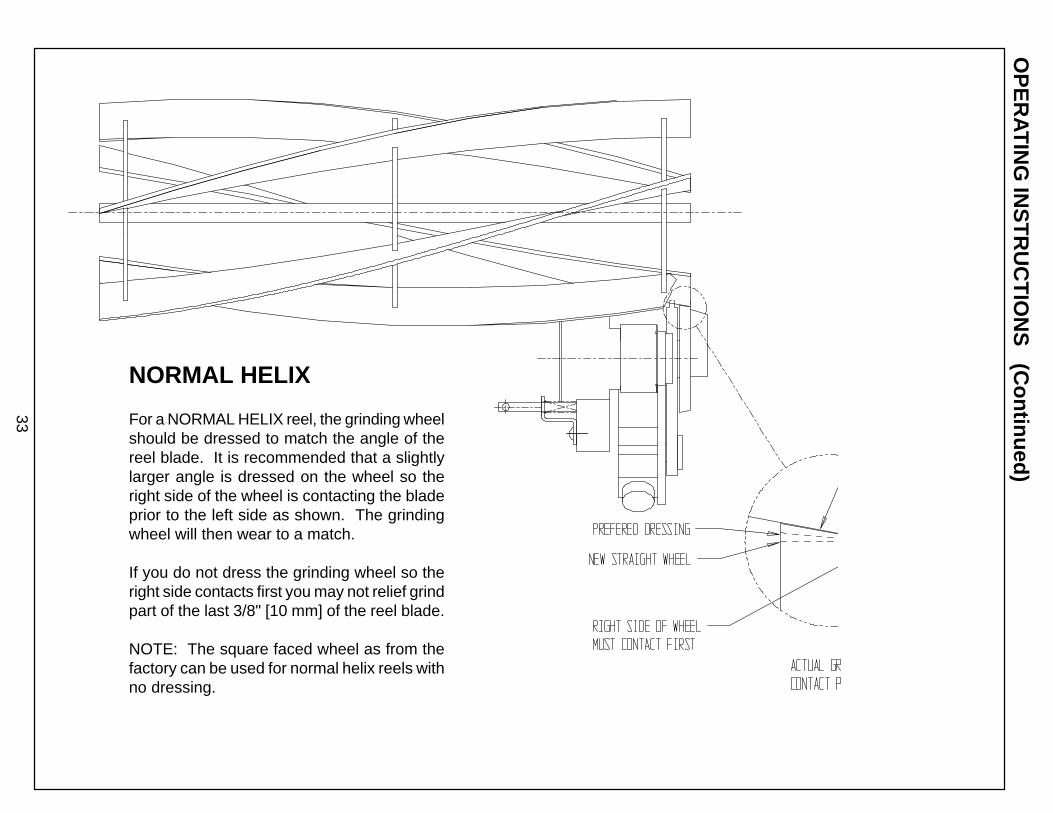
NORMAL HELIX
For a NORMAL HELIX reel, the grinding wheelshould be dressed to match the angle of thereel blade. It is recommended that a slightlylarger angle is dressed on the wheel so theright side of the wheel is contacting the bladeprior to the left side as shown. The grindingwheel will then wear to a match.
If you do not dress the grinding wheel so theright side contacts first you may not relief grindpart of the last 3/8" [10 mm] of the reel blade.
NOTE: The square faced wheel as from thefactory can be used for normal helix reels withno dressing.
OP
ER
ATIN
G IN
ST
RU
CT
ION
S (C
ontinued)

34
For a REVERSE HELIX reel, the grinding wheelshould be dressed to match the angle of thereel blade. It is recommended that a slightlylarger angle is dressed on the wheel so the rightside of the wheel is contacting the blade priorto the left side as shown. The grinding wheelwill then wear to a match.
If you do not dress the grinding wheel so theright side contacts first you may not relief grindpart of the last 3/8" [10 mm] of the blade.
REVERSE HELIX
OP
ER
AT
ING
INS
TR
UC
TIO
NS
(Continued)
NOTE: A wheel that has been worn to match a normalhelix can generally be removed and reversed to grinderreverse helix reels.

35
OPERATING INSTRUCTIONS (Continued)Reset the Traverse Limit Proximity Switch so the grindingwheel clears the reel at both ends by approximately 1/16"[1.5 mm]. Make sure the Reel Positioner Adjuster is set atits mid point. See Relief Angle Adjustment on Page 13.
Pull the left side plunger pin and rotate the Finger and BodyAssembly up (back, away from the operator) into the reliefposition until the left side plunger pin locks into position.See FIG. 33. The plunger pin must be fully engaged to theAdjustable Relief Adjuster for proper function.
Pull the right side locking index finger pin to releasethe index finger and rotate the handle into the retractedposition. See FIG. 33.
Set Grind Selector to variable torque relief. NOTE: Whenyou put the selector in relief, the Finger and Body Assemblymust be up and the index finger must be unlocked and inthe forward position. If this is not done, the spin drive andjog will not function.
Set Auto/Manual selector to manual jog.
Set Spin Drive Rotation switch to rotate the reel into thestop finger, counterclockwise (CCW) when looking at theright side. NOTE: Relief torque reel rotation is alwaysopposite spin rotation.
With the traverse in home position, manually jog the grindinghead up while manually rotating the reel until the index fingertouches the blade.
NOTE: The Index Finger position must be set to stop thereel blade and allow traversing to the left without the bladehitting the side of the relief finger. This position must alsoallow approximately 1/32" [1 mm] free play of the index fingerwhen the blade is resting on the high point of the relief finger.See FIG. 33.
Jog left until the reel blade is on the relief finger. Adjust theindex finger positioning by loosening the Index Lock Handleand rotating the index adjust lever on the right side of thegrinding head. See FIG. 33. When this is completed, lockit into position by tightening the index lock handle.Continue to jog the grinding head up until there is minimalclearance between the reel blade and the grinding wheel.
Check the Proximity Sensor on the Index Finger (right sideproximity switch under the spark shield) to insure that itmakes contact (the proximity switch light on) when the indexfinger catches a reel blade.
FIG. 33
AdjustableIndex Lever
Index FingerT-KnobIndex FingerProximitySensorIndex FingerLocking Pin (inretractedposition)
Index Lock HandlePush Index Finger hereto check for free play
Detail shows Finger and Body Assembly rotated(counterclockwise) into relief grinding position(shown without grinding wheel for clarity).

36
Close and latch the doors, the grinding wheel motor will notoperate with the doors open.
Turn the Spin Drive motor on. NOTE: The spin drive willapply a torque load against the fingers.
Set the Relief Torque Potentiometer at approximately 15.NOTE: Free turning reels may need a lower value than 15.Stiff reels or reels with a drive train may need a higher torquethan 15. Do not exceed 45 on the relief torque potentiometersetting.
Manually jog the traverse all the way to the left watching forproper clearance between the grinding wheel and the blade.Check for proper clearance between the index finger (afterreleasing from blade at far left position) and the front side ofthe blade on the return trip to the home position. Also verifyclearance to the reel blade support spiders.
Stop the traverse in home position and check for a properblade index.
At this point, you can adjust the relief angle by turning theReel Positioner Adjuster. See FIG. 35. You can increase therelief angle approximately 8 degrees by rotating the ReelPositioner Adjuster clockwise. You can decrease the reliefangle approximately 8 degrees by rotating the Reel PositionerAdjuster counterclockwise.
Select a Relief program (6-0). Included with your grinder is alaminated grind chart. It is shipped in the Product PacketAssembly. There is a hook on the side of the control panel tohang the chart. At this time look at the chart and select arelief grinding program based on your best estimate as tohow much material needs to be removed from the reel toachieve the correct relief. Set program number accordinglyusing the thumbwheel marked "N". See FIG. 34.
Set relief blade number to match the number of blades in thereel using the two thumbwheels on the right in FIG. 34.
Not having the number of blades setcorrectly will result in double grindingsome blades or not grinding all the blades.
Set Auto/Manual selector to Auto Program.
Turn on the Spin Drive Motor (should already be on), the DustCollector and the Grinding Wheel Motor.
The LED should then say "RELIEF AUTO CYCLE PRESSPROG START SW".
OPERATING INSTRUCTIONS (Continued)
FIG. 34
FIG. 35
37
OPERATING INSTRUCTIONS (Continued)NOTE: Traverse speed should be approximately 15 fpm.If you are removing a small amount of stock on initial infeeds,faster traverse speeds are suggested. If you are removinga large amount of stock on later infeeds, slower traversespeed may be required.
Push Program Start button and HOLD DOWN until grindingstarts, then release. You should watch the grinder insurethat it is cycling properly prior to leaving the machine inautomatic cycle to do other work.
The program will grind until done it will turn off the dustcollector, spin motor, traverse motor, grinding motor andwill park at the home position. The amber light on top ofthe grinder will flash when the program is completed.
At the end of the program, shut off the switches for theGrinding Wheel Motor, Dust Collector and the SpinDrive Motor.
Open the doors and inspect the relief grind.
Repeat the relief grind if needed.
Reels with one or more blades broken offfrom the outside spider to the edge of thereel cannot be relief ground in automaticcycle. You must relief grind these reelsin the jog mode controlling the traversetravel with the traverse jog switch.

38
Not
e:T
hese
dim
ensi
ons
will
var
y du
e to
ree
l pos
ition
infr
ame,
ree
l dia
., he
ight
of c
ut r
olle
r po
sitio
n, e
tc.
Use
thes
e va
lues
as
a gu
ide
only
.
RE
EL
MA
KE
AN
D M
OD
EL
VE
RT
ICA
LS
CA
LEH
OR
IZO
NTA
LS
CA
LETO
OLI
NG
DIS
TAN
CE
APA
RT
SP
IN D
RIV
EM
OU
NTI
NG
SID
E R
or L
GR
IND
ING
WH
EE
L D
IA.
NO
TES
REEL SETUP CHART
RE
EL
SE
TU
P C
HA
RT

39