650 series ansi engineering manual - abb · pdf file · 2015-05-16section 3...
TRANSCRIPT

Relion® Protection and Control
650 series ANSIEngineering Manual


Document ID: 1MRK 511 261-UUSIssued: June 2012
Revision: AProduct version: 1.2
© Copyright 2012 ABB. All rights reserved

CopyrightThis document and parts thereof must not be reproduced or copied without writtenpermission from ABB, and the contents thereof must not be imparted to a third party,nor used for any unauthorized purpose.
The software and hardware described in this document is furnished under a license andmay be used or disclosed only in accordance with the terms of such license.
TrademarksABB and Relion are registered trademarks of the ABB Group. All other brand orproduct names mentioned in this document may be trademarks or registeredtrademarks of their respective holders.
WarrantyPlease inquire about the terms of warranty from your nearest ABB representative.
ABB Inc.
1021 Main Campus Drive
Raleigh, NC 27606, USA
Toll Free: 1-800-HELP-365, menu option #8
ABB Inc.
3450 Harvester Road
Burlington, ON L7N 3W5, Canada
Toll Free: 1-800-HELP-365, menu option #8
ABB Mexico S.A. de C.V.
Paseo de las Americas No. 31 Lomas Verdes 3a secc.
53125, Naucalpan, Estado De Mexico, MEXICO
Phone: (+1) 440-585-7804, menu option #8

DisclaimerThe data, examples and diagrams in this manual are included solely for the concept orproduct description and are not to be deemed as a statement of guaranteed properties.All persons responsible for applying the equipment addressed in this manual mustsatisfy themselves that each intended application is suitable and acceptable, includingthat any applicable safety or other operational requirements are complied with. Inparticular, any risks in applications where a system failure and/or product failure wouldcreate a risk for harm to property or persons (including but not limited to personalinjuries or death) shall be the sole responsibility of the person or entity applying theequipment, and those so responsible are hereby requested to ensure that all measuresare taken to exclude or mitigate such risks.
This document has been carefully checked by ABB but deviations cannot becompletely ruled out. In case any errors are detected, the reader is kindly requested tonotify the manufacturer. Other than under explicit contractual commitments, in noevent shall ABB be responsible or liable for any loss or damage resulting from the useof this manual or the application of the equipment.

ConformityThis product complies with the directive of the Council of the European Communitieson the approximation of the laws of the Member States relating to electromagneticcompatibility (EMC Directive 2004/108/EC) and concerning electrical equipment foruse within specified voltage limits (Low-voltage directive 2006/95/EC). Thisconformity is the result of tests conducted by ABB in accordance with the productstandards EN 50263 and EN 60255-26 for the EMC directive, and with the productstandards EN 60255-1 and EN 60255-27 for the low voltage directive. The product isdesigned in accordance with the international standards of the IEC 60255 series andANSI C37.90. The DNP protocol implementation in the IED conforms to "DNP3Intelligent Electronic Device (IED) Certification Procedure Subset Level 2", availableat www.dnp.org .

Table of contents
Section 1 Introduction............................................................................5This manual..............................................................................................5Intended audience....................................................................................5Product documentation.............................................................................6
Product documentation set..................................................................6Document revision history...................................................................7Related documents..............................................................................8
Symbols and conventions.........................................................................8Symbols...............................................................................................8Document conventions........................................................................9Functions included in 650 series IEDs................................................9
Section 2 Engineering tool set.............................................................17Introduction.............................................................................................17IED engineering process........................................................................19
Section 3 Engineering process............................................................23Workflow.................................................................................................23
Section 4 Setting up a project.............................................................27PCM600 operates on projects................................................................27Installing Connectivity packages.............................................................27Setting technical key...............................................................................28Setting up communication between PCM600 and the IED.....................31Project managing in PCM600.................................................................36Building a plant structure........................................................................38
IEC 61850 naming conventions to identify an IED............................39Inserting an IED......................................................................................41
Setting IED IP address in the project.................................................53
Section 5 Protection and control engineering......................................57Creating an application configuration with ACT......................................57
Overview............................................................................................57Function blocks..................................................................................58Signals and signal management.......................................................60Function block execution parameters................................................61Configuration parameters..................................................................64
Table of contents
650 series ANSI 1Engineering Manual

Connections and variables................................................................64Hardware channels............................................................................65Validation...........................................................................................66
Setting configuration and setting parameters in PST.............................68Connecting signals in SMT.....................................................................69
Section 6 Local HMI engineering........................................................73LED and function key engineering..........................................................73
Local HMI engineering process.........................................................73LED operation modes........................................................................78
Single-line diagram engineering.............................................................84Concept description to present and generate diagrams ingraphical display editor......................................................................84Supported single-line diagram symbols.............................................89Bay configuration engineering...........................................................92
Events and indications............................................................................97
Section 7 IEC 61850 communication engineering..............................99IEC 61850 interface in the IED and tools................................................99
Function view for IEC 61850 in PCM600...........................................99IEC 61850 interface in IED................................................................99
GOOSE data exchange..............................................................100Station configuration description file types......................................101
IEC 61850 engineering procedure........................................................102IEC 61850 protocol references and pre-conditions.........................102Sequence for engineering of IEC 61850 protocol............................102
Exporting SCL files from PCM600........................................................104Exporting SCD files.........................................................................104Exporting ICD or CID files................................................................105
Engineering of vertical and horizontal communication in IET600.........106Importing SCL files to PCM600............................................................107
Importing SCD files..........................................................................108Importing ICD or CID files................................................................110
Writing communication configuration to IED ........................................111
Section 8 IEC 60870-5-103 communication engineering..................113Engineering in PCM600........................................................................113
Selecting to communicate IEC60870-5-103 data via RS485serial interface on COM05 module.............................................113Selecting to communicate IEC60870-5-103 data via opticalserial interface on COM05 module.............................................114
Table of contents
2 650 series ANSIEngineering Manual

Section 9 DNP3 communication engineering....................................115Signal configuration user information...................................................115Adding setting groups...........................................................................116Configuring DNP3 protocol signals.......................................................118Setting DNP3 signal parameters..........................................................121
Configuring DNP3 class..................................................................122Selecting to communicate DNP3 data via RS485 serialinterface on COM05 module............................................................123
RS485 specific parameters........................................................123Selecting to communicate DNP3 data via optical serialinterface on COM05 module............................................................123
Section 10 Glossary............................................................................125
Table of contents
650 series ANSI 3Engineering Manual

4
Section 1 Introduction
1.1 This manual
The engineering manual contains instructions on how to engineer the IEDs using thedifferent tools in PCM600. The manual provides instructions on how to set up aPCM600 project and insert IEDs to the project structure. The manual also recommendsa sequence for engineering of protection and control functions, LHMI functions as wellas communication engineering for IEC 60870-5-103, IEC 61850 and DNP3.
1.2 Intended audience
This manual addresses system and project engineers involved in the engineeringprocess of a project, and installation and commissioning personnel, who use technicaldata during engineering, installation and commissioning, and in normal service.
The system engineer must have a thorough knowledge of protection and/or controlsystems, protection and/or control equipment, protection and/or control functions andthe configured functional logics in the IEDs. The installation and commissioningpersonnel must have a basic knowledge of handling electronic equipment.
1MRK 511 261-UUS A Section 1Introduction
650 series ANSI 5Engineering Manual
1.3 Product documentation
1.3.1 Product documentation set
Pla
nnin
g &
pur
chas
e
Eng
inee
ring
Inst
allin
g
Com
mis
sion
ing
Ope
ratio
n
Mai
nten
ance
Dec
omm
issi
onin
gde
inst
allin
g&
dis
posa
l
Application manual
Operation manual
Installation manual
Service manual
Engineering manual
Commissioning manual
Communication protocolmanual
Technical manual
Pla
nnin
g &
pur
chas
e
Eng
inee
ring
Inst
allin
g
Com
mis
sion
ing
Ope
ratio
n
Mai
nten
ance
Dec
omm
issi
onin
gde
inst
allin
g&
dis
posa
l
Pla
nnin
g &
pur
chas
e
Eng
inee
ring
Inst
allin
g
Com
mis
sion
ing
Ope
ratio
n
Mai
nten
ance
Dec
omm
issi
onin
gde
inst
allin
g&
dis
posa
l
Application manualApplication manual
Operation manualOperation manual
Installation manualInstallation manual
Service manualService manual
Engineering manualEngineering manual
Commissioning manualCommissioning manual
Communication protocolmanualCommunication protocolmanual
Technical manualTechnical manual
en07000220.vsd
IEC07000220 V1 EN
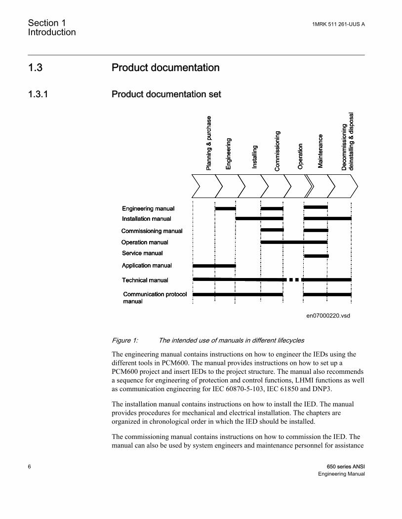
Figure 1: The intended use of manuals in different lifecycles
The engineering manual contains instructions on how to engineer the IEDs using thedifferent tools in PCM600. The manual provides instructions on how to set up aPCM600 project and insert IEDs to the project structure. The manual also recommendsa sequence for engineering of protection and control functions, LHMI functions as wellas communication engineering for IEC 60870-5-103, IEC 61850 and DNP3.
The installation manual contains instructions on how to install the IED. The manualprovides procedures for mechanical and electrical installation. The chapters areorganized in chronological order in which the IED should be installed.
The commissioning manual contains instructions on how to commission the IED. Themanual can also be used by system engineers and maintenance personnel for assistance
Section 1 1MRK 511 261-UUS AIntroduction
6 650 series ANSIEngineering Manual
during the testing phase. The manual provides procedures for checking of externalcircuitry and energizing the IED, parameter setting and configuration as well asverifying settings by secondary injection. The manual describes the process of testingan IED in a substation which is not in service. The chapters are organized inchronological order in which the IED should be commissioned.
The operation manual contains instructions on how to operate the IED once it has beencommissioned. The manual provides instructions for monitoring, controlling andsetting the IED. The manual also describes how to identify disturbances and how toview calculated and measured power grid data to determine the cause of a fault.
The service manual contains instructions on how to service and maintain the IED. Themanual also provides procedures for de-energizing, de-commissioning and disposal ofthe IED.
The application manual contains application descriptions and setting guidelines sortedper function. The manual can be used to find out when and for what purpose a typicalprotection function can be used. The manual can also be used when calculating settings.
The technical manual contains application and functionality descriptions and listsfunction blocks, logic diagrams, input and output signals, setting parameters andtechnical data sorted per function. The manual can be used as a technical referenceduring the engineering phase, installation and commissioning phase, and during normalservice.
The communication protocol manual describes a communication protocol supported bythe IED. The manual concentrates on vendor-specific implementations.
The point list manual describes the outlook and properties of the data points specific tothe IED. The manual should be used in conjunction with the correspondingcommunication protocol manual.
1.3.2 Document revision historyDocument revision/date History-/March 2012 First release
A/June 2012 Minor corrections made
1MRK 511 261-UUS A Section 1Introduction
650 series ANSI 7Engineering Manual

1.3.3 Related documents650 series manuals Identity numberCommunication protocol manual, DNP3 1MRK 511 257-UUS
Communication protocol manual, IEC 61850–8–1 1MRK 511 258-UUS
Communication protocol manual, IEC 60870-5-103 1MRK 511 259-UUS
Cyber Security deployment guidelines 1MRK 511 268-UUS
Point list manual, DNP3 1MRK 511 260-UUS
Engineering manual 1MRK 511 261-UUS
Operation manual 1MRK 500 095-UUS
Installation manual 1MRK 514 015-UUS
1.4 Symbols and conventions
1.4.1 Symbols
The caution icon indicates important information or warning related tothe concept discussed in the text. It might indicate the presence of ahazard which could result in corruption of software or damage toequipment or property.
The information icon alerts the reader of important facts and conditions.
The tip icon indicates advice on, for example, how to design yourproject or how to use a certain function.
Although warning hazards are related to personal injury, it is necessary to understandthat under certain operational conditions, operation of damaged equipment may resultin degraded process performance leading to personal injury or death. Therefore,comply fully with all warning and caution notices.
Operation of damaged equipment could, under certain operational conditions, result indegraded process performance leading to information or property loss. Therefore,comply fully with all notices.
Section 1 1MRK 511 261-UUS AIntroduction
8 650 series ANSIEngineering Manual

1.4.2 Document conventionsA particular convention may not be used in this manual.
• Abbreviations and acronyms in this manual are spelled out in the glossary. Theglossary also contains definitions of important terms.
• Push button navigation in the LHMI menu structure is presented by using the pushbutton icons.To navigate between the options, use and .
• HMI menu paths are presented in bold.Select Main menu/Settings.
• LHMI messages are shown in Courier font.To save the changes in non-volatile memory, select Yes and press .
• Parameter names are shown in italics.The function can be enabled and disabled with the Operation setting.
• The ^ character in front of an input or output signal name in the function blocksymbol given for a function, indicates that the user can set an own signal name inPCM600.
• The * character after an input or output signal name in the function block symbolgiven for a function, indicates that the signal must be connected to anotherfunction block in the application configuration to achieve a valid applicationconfiguration.
• Dimensions are provided both in inches and mm. If it is not specifically mentionedthen the dimension is in mm.
1.4.3 Functions included in 650 series IEDsTable 1: Main protection functions
IEC 61850 / Function blockname
ANSI Function description
T2WPDIF 87T Transformer differential protection, two winding
T3WPDIF 87T Transformer differential protection, three winding
REFPDIF 87N Restricted ground fault protection, low impedance
HZPDIF 87 1Ph High impedance differential protection
GENPDIF 87G Generator differential protection
ZQMPDIS 21 Five-zone distance protection, Quadrilateral and Mho characteristic
FDPSPDIS 21 Phase selection with load enchroachment, quadrilateral characteristic
FMPSPDIS 21 Faulty phase identification with load enchroachment for mho
ZDARDIR 21 Additional distance protection directional function for ground faults
ZDNRDIR 21 Directional impedance quadrilateral and mho
Table continues on next page
1MRK 511 261-UUS A Section 1Introduction
650 series ANSI 9Engineering Manual

IEC 61850 / Function blockname
ANSI Function description
PPLPHIZ Phase preference logic
ZMRPSB 68 Power swing detection
ZCVPSOF Automatic switch onto fault logic, voltage-and current-based
ZGCPDIS 21G Underimpedance protection for generators and transformers
LEXPDIS 40 Loss of excitation
OOSPPAM 78 Out-of-step protection
LEPDIS Load enchroachment
Table 2: Backup protection functions
IEC 61850 / Functionblock name
ANSI Function description
Current protection
PHPIOC 50 Instantaneous phase overcurrent protection
SPTPIOC 50 Instantaneous phase overcurrent protection
OC4PTOC 51/67 Four-step phase overcurrent protection
OC4SPTOC 51/67 Four-step phase overcurrent protection
EFPIOC 50N Instantaneous residual overcurrent protection
EF4PTOC 51N/67N Four-step directional residual overcurrent protection
SDEPSDE 67N Sensitive directional residual overcurrent and power protection
UC2PTUC 37 Time-delayed two-step undercurrent protection
LCPTTR 26 Thermal overload protection, one time constant, Celsius
LFPTTR 26 Thermal overload protection, one time constant, Fahrenheit
TRPTTR 49 Thermal overload protection, two time constants
CCRBRF 50BF Breaker failure protection
CSPRBRF 50BF Breaker failure protection
STBPTOC 50STB Stub protection
CCRPLD 52PD Pole discordance protection
BRCPTOC 46 Broken conductor check
GUPPDUP 37 Directional underpower protection
GOPPDOP 32 Directional overpower protection
DNSPTOC 46 Negative sequence-based overcurrent function
AEGGAPC 50AE Accidental energizing protection for synchronous generator
NS2PTOC 46I2 Negative-sequence time overcurrent protection for machines
VR2PVOC 51V Voltage-restrained time overcurrent protection
Table continues on next page
Section 1 1MRK 511 261-UUS AIntroduction
10 650 series ANSIEngineering Manual

IEC 61850 / Functionblock name
ANSI Function description
Voltage protection
UV2PTUV 27 Two-step undervoltage protection
OV2PTOV 59 Two-step overvoltage protection
ROV2PTOV 59N Two-step residual overvoltage protection
OEXPVPH 24 Overexcitation protection
LOVPTUV 27 Loss-of-voltage check
STEFPHIZ 59THD 100% Stator ground fault protection, 3rd harmonic based
Frequency protection
SAPTUF 81 Underfrequency function
SAPTOF 81 Overfrequency function
SAPFRC 81 Rate-of-change frequency protection
Table 3: Control and monitoring functions
IEC 61850 / Functionblock name
ANSI Function description
Control
SESRSYN 25 Synchrocheck, energizing check and synchronizing
SMBRREC 79 Autorecloser
STBRREC 79 Autorecloser
SCILO 3 Logical node for interlocking
BB_ES 3 Interlocking for busbar grounding switch
A1A2_BS 3 Interlocking for bus-section breaker
A1A2_DC 3 Interlocking for bus-section disconnector
ABC_BC 3 Interlocking for bus-coupler bay
BH_CONN 3 Interlocking for 1 1/2 breaker diameter
BH_LINE_A 3 Interlocking for 1 1/2 breaker diameter
BH_LINE_B 3 Interlocking for 1 1/2 breaker diameter
DB_BUS_A 3 Interlocking for double CB bay
DB_BUS_B 3 Interlocking for double CB bay
DB_LINE 3 Interlocking for double CB bay
ABC_LINE 3 Interlocking for line bay
AB_TRAFO 3 Interlocking for transformer bay
SCSWI Switch controller
SXCBR Circuit breaker
Table continues on next page
1MRK 511 261-UUS A Section 1Introduction
650 series ANSI 11Engineering Manual

IEC 61850 / Functionblock name
ANSI Function description
SXSWI Circuit switch
POS_EVAL Evaluation of position indication
SELGGIO Select release
QCBAY Bay control
LOCREM Handling of LR-switch positions
LOCREMCTRL LHMI control of PSTO
APC8 Apparatus control for single bay, max 8 app. (1CB) incl. interlocking
TR8ATCC 90 Automatic voltage control for tap changer, parallel control
TCMYLTC 84 Tap changer control and supervision, 6 binary inputs
SLGGIO Logic-rotating Switch for function selection and LHMI presentation
VSGGIO Selector mini switch extension
DPGGIO IEC61850 generic communication I/O functions double point
SPC8GGIO Single-point generic control 8 signals
AUTOBITS AutomationBits, command function for DNP3.0
I103CMD Function commands for IEC60870-5-103
I103IEDCMD IED commands for IEC60870-5-103
I103USRCMD Function commands user defined for IEC60870-5-103
I103GENCMD Function commands generic for IEC60870-5-103
I103POSCMD IED commands with position and select for IEC60870-5-103
Secondary system supervision
CCSRDIF 87 Current circuit supervision
SDDRFUF Fuse failure supervision
TCSSCBR Breaker close/trip circuit monitoring
Logic
SMPPTRC 94 Tripping logic
SPTPTRC 94 Tripping logic
TMAGGIO Trip matrix logic
OR Configurable logic blocks, OR
INVERTER Configurable logic blocks, Inverter
PULSETIMER Configurable logic blocks, PULSETIMER
GATE Configurable logic blocks, Controllable gate
XOR Configurable logic blocks, exclusive OR
LOOPDELAY Configurable logic blocks, loop delay
TimerSet Configurable logic blocks, timer
AND Configurable logic blocks, AND
Table continues on next page
Section 1 1MRK 511 261-UUS AIntroduction
12 650 series ANSIEngineering Manual

IEC 61850 / Functionblock name
ANSI Function description
SRMEMORY Configurable logic blocks, set-reset memory
RSMEMORY Configurable logic blocks, reset-set memory
FXDSIGN Fixed-signal function block
B16I Boolean 16 to Integer conversion
B16IFCVI Boolean 16 to Integer conversion with logic node representation
IB16A Integer to Boolean 16 conversion
IB16FCVB Integer to boolean 16 conversion with logic node representation
Monitoring
CVMMXN Measurements
CMMXU Phase current measurement
VMMXU Phase-phase voltage measurement
CMSQI Current sequence component measurement
VMSQI Voltage sequence measurement
VNMMXU Phase-neutral voltage measurement
AISVBAS Function block for service values presentation of the analog inputs
TM_P_P2 Function block for service value presentation of primary analog inputs 600TRM
AM_P_P4 Function block for service value presentation of primary analog inputs 600AIM
TM_S_P2 Function block for service value presentation of secondary analog inputs 600TRM
AM_S_P4 Function block for service value presentation of secondary analog inputs 600AIM
CNTGGIO Event counter
DRPRDRE Disturbance report
AxRADR Analog input signals
BxRBDR Binary input signals
SPGGIO IEC61850 generic communication I/O functions
SP16GGIO IEC61850 generic communication I/O functions 16 inputs
MVGGIO IEC61850 generic communication I/O functions
MVEXP Measured value expander block
LMBRFLO Fault locator
SPVNZBAT Station battery supervision
SSIMG 63 Insulation gas-monitoring function
SSIML 71 Insulation liquid-monitoring function
SSCBR Circuit breaker condition monitoring
I103MEAS Measurands for IEC60870-5-103
I103MEASUSR Measurands user defined signals for IEC60870-5-103
I103AR Function status auto-recloser for IEC60870-5-103
Table continues on next page
1MRK 511 261-UUS A Section 1Introduction
650 series ANSI 13Engineering Manual
IEC 61850 / Functionblock name
ANSI Function description
I103EF Function status ground-fault for IEC60870-5-103
I103FLTPROT Function status fault protection for IEC60870-5-103
I103IED IED status for IEC60870-5-103
I103SUPERV Supervision status for IEC60870-5-103
I103USRDEF Status for user defiend signals for IEC60870-5-103
Metering
PCGGIO Pulse counter logic
ETPMMTR Function for energy calculation and demand handling
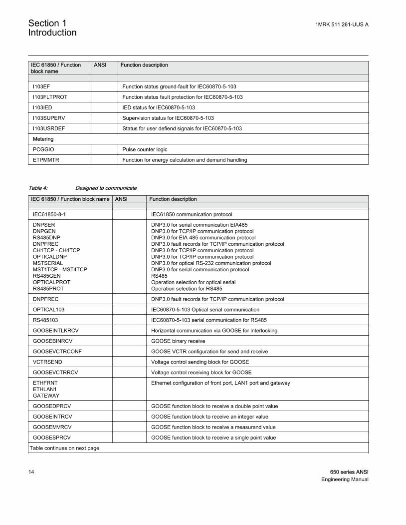
Table 4: Designed to communicate
IEC 61850 / Function block name ANSI Function description IEC61850-8-1 IEC61850 communication protocol
DNPSERDNPGENRS485DNPDNPFRECCH1TCP - CH4TCPOPTICALDNPMSTSERIALMST1TCP - MST4TCPRS485GENOPTICALPROTRS485PROT
DNP3.0 for serial communication EIA485DNP3.0 for TCP/IP communication protocolDNP3.0 for EIA-485 communication protocolDNP3.0 fault records for TCP/IP communication protocolDNP3.0 for TCP/IP communication protocolDNP3.0 for TCP/IP communication protocolDNP3.0 for optical RS-232 communication protocolDNP3.0 for serial communication protocolRS485Operation selection for optical serialOperation selection for RS485
DNPFREC DNP3.0 fault records for TCP/IP communication protocol
OPTICAL103 IEC60870-5-103 Optical serial communication
RS485103 IEC60870-5-103 serial communication for RS485
GOOSEINTLKRCV Horizontal communication via GOOSE for interlocking
GOOSEBINRCV GOOSE binary receive
GOOSEVCTRCONF GOOSE VCTR configuration for send and receive
VCTRSEND Voltage control sending block for GOOSE
GOOSEVCTRRCV Voltage control receiving block for GOOSE
ETHFRNTETHLAN1GATEWAY
Ethernet configuration of front port, LAN1 port and gateway
GOOSEDPRCV GOOSE function block to receive a double point value
GOOSEINTRCV GOOSE function block to receive an integer value
GOOSEMVRCV GOOSE function block to receive a measurand value
GOOSESPRCV GOOSE function block to receive a single point value
Table continues on next page
Section 1 1MRK 511 261-UUS AIntroduction
14 650 series ANSIEngineering Manual

IEC 61850 / Function block name ANSI Function description ZCPSCH 85 Scheme communication logic with delta based blocking scheme signal transmit
ZCRWPSCH 85 Current reversal and weak end infeed logic for distance protection
ZCWSPSCH 85 Current reversal and weak end infeed logic for distance protection
ZCLCPLAL Local acceleration logic
ECPSCH 85 Scheme communication logic for residual overcurrent protection
ECRWPSCH 85 Current reversal and weak end infeed logic for residual overcurrent protection
Table 5: Basic IED functions
IEC 61850 / Functionblock name
Function description
Basic functions included in all products
INTERRSIG Self-supervision with internal event list
SELFSUPEVLST Self-supervision with internal event list
TIMESYNCHGEN Time synchronization
SNTP Time synchronization
DTSBEGIN Time synchronization
DTSEND Time synchronization
TIMEZONE Time synchronization
IRIG-B Time synchronization
SETGRPS Setting group handling
ACTVGRP Parameter setting groups
TESTMODE Test mode functionality
CHNGLCK Change lock function
ATHSTAT Authority status
ATHCHCK Authority check
TERMINALID IED identifiers
PRODINF Product information
PRIMVAL Primary system values
SMAI_20_1 -SMAI_20_12
Signal Matrix for analog inputs
3PHSUM Summation block 3 phase
GBASVAL Global base values for settings
DOSFRNT Denial of service, frame rate control for front port
DOSLAN1 Denial of service, frame rate control for LAN1 port
DOSSCKT Denial of service, socket flow control
1MRK 511 261-UUS A Section 1Introduction
650 series ANSI 15Engineering Manual

16

Section 2 Engineering tool set
2.1 Introduction
The structure of a monitoring and control system for electrical substations has aprinciple structure as shown in Figure 2. It contains a number of IEDs for the variouspurposes.
For performance reasons, do not insert more than 150 IEDs of 650series type in one PCM600 project. In PCM600 version 2.3, themaximum number of IEDs is 60. Larger projects can be divided intoseveral PCM600 projects.
It can be subdivided in the three main parts:
• Bay level IEDs• Station communication• Station level IEDs
IEC08000101.vsd
Bay level
Station level
StationCommunication
Station bus
bayIED 1
bayIED 2
bayIED n-1
bayIED n
NCC-GW(station-IED2)
PCM600(tool set)
HSI(station-IED1)
IEC08000101 V1 EN
Figure 2: Principle structure of a monitoring and control system for a substation
All three parts require specific engineering and configuration. PCM600 is used to dothe complete engineering and configuration activities needed for bay level IEDs.
1MRK 511 261-UUS A Section 2Engineering tool set
650 series ANSI 17Engineering Manual
Product type and version specific engineering data needed by PCM600 for protection,control and communication engineering of a particular bay IED is given in an IEDconnectivity package.
PCM600 communicates with the bay IEDs via an Ethernet connection. The connectionallows to reading and writing all configuration data needed for proper operation fromor to the IED. The IEDs have communication interfaces for protocols and media usedfor station communication. IEC 61850 communication files for a bay IED or acomplete station can be exported from PCM600 to station engineering tools forengineering of station communication between bay IEDs and station IEDs.
A PC with PCM600 can be connected to any 650 series IED within a station using theEthernet connection.
The Ethernet connection can then later also be used for service and maintenancepurposes. The connection is also used to handle disturbance records in COMTRADEformat from protection IEDs using the IEC 61850 file transfer.
The IEDs of today are designed on the concept of the IEC 61850 standard. This ismainly given for the organization of functions represented by an equivalent logicalnode in the IEC 61850 standard. The mapping between the logical node data model inthe IED, following the structure and rules in part 7 of the IEC 61850 standard, and thefunction blocks in an IED configuration is given in the IEC 61850 communicationprotocol manual.
The concept is also used for DNP3 protocol. The signals used or delivered by afunction block are automatically generated and available for station communication.This concept allows a very efficient cost saving signal engineering.
The IEC 60870-5-103 protocol is engineered in Application Configuration tool andParameter Setting tool.
The engineering of the used communication protocols is a separate task and an additionto the engineering of protection and control functions.
PCM600 can be used for different purposes throughout the IED life cycle. A set ofspecial tools is available for different applications.
The applications can be organized in:
• IED product engineering• IED communication engineering per protocol• IED system monitoring• IED product diagnostic
This manual is valid for PCM600 supporting the 650 series product.
Section 2 1MRK 511 261-UUS AEngineering tool set
18 650 series ANSIEngineering Manual

2.2 IED engineering process
PCM600 is used for various tasks in the IED engineering process. See Figure 3:
• IED engineering management• Organizing the bay IEDs in the structure of the substation by defining
voltage levels and bays below the substation. A PCM600 project can haveonly one substation.
• Configuring the IED functions (for example protection and control functionsand LHMI functions) by using the Application Configuration tool.
• Configuring the parameters and setting values for the IED itself and for theprocess functionality by using the Parameter Setting tool.
• Drawing single line diagrams and do the link to dynamic process values byusing the Graphical Display Editor tool. The single line diagrams are shownon the LHMI on the bay IED.
• Configuring connections between the application configuration functionblocks and physical hardware input and outputs by using the Signal Matrixtool or the Application Configuration tool.
• Communication engineering• IEC 61850 station communication engineering is done with a separate tool,
IET600. PCM600 interacts with IET600 by importing and exporting SCL files.• Organizing GOOSE messages received and managing the used IO signal is
done by using the Signal Matrix tool.• Communication engineering for the DNP3 protocol by using the
Communication Management tool.• Communication engineering for the IEC 60870-5-103 protocol by using
Application Configuration tool and Parameter Setting tool.• Disturbance record management
• Generating overviews about the available (disturbance) recordings in allconnected protection IEDs by using the Disturbance Handling tool.
• Manually reading the recording files (in COMTRADE format) from theprotection IEDs by using the Disturbance Handling tool or automatically byusing the PCM600 scheduler.
• Managing recording files with the assistance of the Disturbance Handling tool.• Creating overview reports of recording file content for fast evaluation with
assistance of the Disturbance Handling tool.• Service management
1MRK 511 261-UUS A Section 2Engineering tool set
650 series ANSI 19Engineering Manual

• Monitoring selected signals of an IED for commissioning or servicepurposes by using the Signal Monitoring tool.
• Listing all actual existing IED internal events by using the Event Viewer tool.• Listing all actual pending process events as they are stored in the IED
internal disturbance report event list by using the Event Viewer tool.
IEC08000100.vsd
PCM600
IED Engineering Management
Project ACT
SMT
HWT
GDE
PST
Communication Management
CMT
Operator Disturbance Record Management
DRH
Service Management
MON EVT
SMT
IEC08000100 V1 EN
Figure 3: Organization of PCM600 in different management tasks
Additional functionality to manage the project and to organize the user rights:
• PCM600 user management• Organizing users with their rights, profile and password to use the different
tools and activities within the tools.• Defining allowed activities for the user profiles to use tools in PCM600.
• IED user management• Organizing users with their rights, profile and password to read and write
files of the IED.• Defining allowed activities for the user profiles to use the read and write
function.
Section 2 1MRK 511 261-UUS AEngineering tool set
20 650 series ANSIEngineering Manual

Once the engineering of the IED is done, the results must be written to the IED.Conversely some parts of the engineering information can be uploaded from the IEDfor various purposes.
The connection between the physical IED and PCM600 is established via an Ethernetlink on the front or rear port on the IED.
1MRK 511 261-UUS A Section 2Engineering tool set
650 series ANSI 21Engineering Manual

22

Section 3 Engineering process
3.1 Workflow
1MRK 511 261-UUS A Section 3Engineering process
650 series ANSI 23Engineering Manual

IEC08000122.vsd
Make GOOSE connections
Export SCL files from PCM600
Import SCL files to IET600 and do signal engineering. Export SCL files from IET600.
Import SCL files to PCM600
Write configurationto IED
Start
HWT
ACT/SMT
PST
GDE
SMT
CMT
ExportSCD
IEDWRITE
IET600
ImportSCD
IEDWRITE
EndEnd
Optional, can be used to add additional hardware modules
Configure IED functionality
Parametrization
Signal engineering
Create Single line diagramfor local HMI
Save the work between the
different steps
ProjectCreate plant structure
Write configurationto IED
IEC61850Supported protocols
IEC08000122 V2 EN
Figure 4: IED engineering workflow
The described sequence in Figure 4 is a proposal based on practical experience anddependencies of the steps. It is possible to do a different sequence based on theavailable information at the time the project is started. This means that severaliterations may be needed to finish the project.
• Setting up the PCM600 project
Section 3 1MRK 511 261-UUS AEngineering process
24 650 series ANSIEngineering Manual

• Build the plant structure according to the substation structure.
For performance reasons, do not insert more than 150 IEDsof 650 series type in one PCM600 project. Larger projectscan be divided into several PCM600 projects.
• Insert an IED in plant structure which can be done in many ways. Byinserting the IED in online mode where the configuration is read from thephysical IED, by inserting an IED in offline mode, by importing a *.pcmifile or by selecting an IED template from the template library (*.pcmt).
• Rename the IED objects in PCM600 to the projects definitions.• ACT Application configuration
• Configure the protection or control function for example for a transformerapplication as requested.
• Save the configuration made with ACT to make the interfaces and signalsavailable for other engineering tools within PCM600, for example for PST.
• PST Parameter setting and configuration• Check the configuration parameters of the physical IED for communication
channels, CT and VT conversion values of the transformer module, forexample.
• Check and adjust if needed the setting values for example for:• Presentation parameters for local HMI.• Settings for protection or control functions.• Number of setting groups.
• GDE Single line diagram configuration• Create a single line diagram.• Include measurements when needed.• Link the dynamic elements to functions created in ACT, for example a
breaker object to the switch function.• Local HMI engineering
• Include and engineer the function blocks for LHMI element groups withACT.
• Configure the function keys and LEDs with ACT.• Define the function key and LED behavior with PST.
• Communication protocol engineering• The engineering steps are protocol dependent.• Use the communication management tool (CMT) for DNP3 engineering.• Use the IET600 station configuration tool for IEC 61850 engineering. See
the application manual for other protocols (IEC103).
1MRK 511 261-UUS A Section 3Engineering process
650 series ANSI 25Engineering Manual

The IED restarts automatically when writing an IED configurationwhere changes have been made to, for example, configurationparameters. It is not possible to communicate with the IED during therestart.
The IED does not restart after reconfiguring IEC61850 (regardless ofwhether the protocol is enabled or disabled prior to reconfiguring). TheIED will reboot at the next PCM600 to IED write operation only incase there are errors while configuring the IEC61850 protocol at themost recent attempt.
Section 3 1MRK 511 261-UUS AEngineering process
26 650 series ANSIEngineering Manual

Section 4 Setting up a project
4.1 PCM600 operates on projects
A typical project in PCM600 contains a plant structure including one or several IEDobjects, where each IED object contains the engineering data created or modified usingthe different PCM600 tools.
Several projects can be created and managed by PCM600, but only one project can beactive at a time.
4.2 Installing Connectivity packages
A Connectivity package contains the complete description of the IED data signals,parameters and protocol addresses for a certain IED type and version. Several types ofIEDs can be managed in one PCM600 project, thus the corresponding Connectivitypackage has to be installed on the PC. Connectivity Packages and ConnectivityPackage Updates are managed in the Update Manager.
PCM600 must be installed before the connectivity packages can beinstalled.
A Connectivity package for a specific IED type and version is divided in two parts. TheIED connectivity package base module is common for all 650 series IEDs. The IEDspecific module is separate for each type of IED.
Installing IED Connectivity packageThe Connectivity package is available on the CD that was distributed along with theIED.
Procedure
1. Close PCM600 before running the IED Connectivity Package RE_650.exeinstallation wizard.
2. Select the IED type(s) to install in the installation wizard window, for exampleREL650 module 1.0.0 Module v.n. (n = version number).The installation softwareguides the user through steps required to install the IED Connectivity packagebase module and the specific IED type modules. The IED specific module is
1MRK 511 261-UUS A Section 4Setting up a project
650 series ANSI 27Engineering Manual

installed to same location as for IEDConnectivity package base module. Thedefault directory is C:/Program Files/ABB/Connectivity Packages/IEDConnPackRE_650.
4.3 Setting technical key
Both a physical IED and an IED object in PCM600 have a technical key. The purposeof the technical key is to prevent download of a configuration to wrong IED. Thetechnical key in the IED and PCM600 must be the same, otherwise it is not possible todownload a configuration. Each IED in a PCM600 project must have a uniquetechnical key. It is therefor not possible to set the same technical key for several IEDsin the same PCM600 project.
The technical key property in PCM600 corresponds to the IED nameattribute in SCL files. Avoid changing the IED name attribute outsidePCM600, because data in PCM600 might be lost when importing SCLfiles.
The IED technical key and the PCM600 technical key must be the samefor successful communication between the IED and PCM600.
When using PCM600 for writing to the IED, it is important that theLHMI is not in a menu position where settings can be made. Only oneactive transaction, from LHMI or PCM600, is allowed at any one time.
When writing a configuration to the IED, PCM600 checks the mismatch between theIED object and the physical IED technical key, if any. For communication between theIED and PCM600 the technical key must be the same. Users have the option to readthe technical key from the IED and update it to PCM600 or write the PCM600technical key to the IED. The user can also define an own technical key. The errormessage displayed due to mismatch between PCM600 and IED technical key is shownin Figure 5.
Section 4 1MRK 511 261-UUS ASetting up a project
28 650 series ANSIEngineering Manual

IEC09000378-1-en.vsdIEC09000378 V1 EN
Figure 5: Error message due to mismatch between PCM600 and IED technical key
Be sure that the IED object in PCM600 has the same IP address as thephysical IED, which is intended to be connected through the technicalkey concept.
The technical key for an IED object in PCM600 can also be changed inthe Object properties window.
1. Select the IED in the Plant Structure.2. Right-click and select Set Technical Key, see Figure 6.
1MRK 511 261-UUS A Section 4Setting up a project
650 series ANSI 29Engineering Manual

IEC09000667-2-en.vsdIEC09000667 V2 EN
Figure 6: PCM600: Set technical key menu at IED level
A dialog window opens to inform about the technical key concept.3. Click OK in the dialog window.
The technical key is read from the IED and the technical key editor windowopens, see Figure 7.
Section 4 1MRK 511 261-UUS ASetting up a project
30 650 series ANSIEngineering Manual

IEC09000380-1-en.vsdIEC09000380 V1 EN
Figure 7: PCM600: Technical key editor
Using the Technical Key Editor the following selections are possible.• use the existing technical key in the IED• use the existing technical key defined for the IED object in PCM600 or• set a user defined technical key, which changes the technical key for both
the physical IED and IED object in PCM600.
Do not use a technical key with more than 13 characters.
4. Click OK to confirm the selection.It is not possible to set a user defined name or select the Technical key in IED ifthe value is the same as already given to another IED object in the PCM600project. A dialog window opens if this is the case.
4.4 Setting up communication between PCM600 and theIED
The communication between the IED and PCM600 is independent of thecommunication protocol used within the substation or to the NCC.
The communication media is always Ethernet and the used protocol is TCP/IP.
Each IED has an RJ-45 Ethernet interface connector on the front and on the rear side.The Ethernet connector can be used for communication with PCM600.
When an Ethernet-based station protocol is used, PCM600 communication can use thesame Ethernet port and IP address.
1MRK 511 261-UUS A Section 4Setting up a project
650 series ANSI 31Engineering Manual

To connect PCM600 to the IED, two basic variants must be considered.
• Direct point-to-point link between PCM600 and the IED front port.• Indirect link via a station LAN or from remote via a network.
The physical connection and the IP address must be configured in both cases to enablecommunication.
The communication procedures are the same in both cases.
1. If needed, set the IP address for the IEDs.2. Set up the PC or workstation for a direct link (point-to-point), or3. Connect the PC or workstation to the LAN/WAN network.4. Configure the IED IP addresses in the PCM600 project for each IED to match the
IP addresses of the physical IEDs.
Setting up IP addressesThe IP address and the corresponding mask must be set via the LHMI for eachavailable Ethernet interface in the IED. Each Ethernet interface has a default factory IPaddress when the IED is delivered. This is not given when an additional Ethernetinterface is installed or an interface is replaced.
• The default IP address for the IED front port is 10.1.150.3 and the correspondingsubnetwork mask is 255.255.255.0, which can be set via the local HMI path Mainmenu/Configuration/Communication/TCP-IP configuration/1:ETHFRNT.
• The default IP address for the IED rear port is 192.168.1.10 and the correspondingsubnetwork mask is 255.255.255.0, which can be set via the local HMI path Mainmenu/Configuration/Communication/TCP-IP configuration/1:ETHLAN1 andRear OEM - port CD.
The front and rear port IP addresses cannot belong to the same subnetor communication will fail. It is recommended to change the IP addressof the front port, if the front and rear port are set to the same subnet.
Setting up the PC or workstation for point-to-point access to IEDs frontportA special cable is needed to connect two physical Ethernet interfaces together withouta hub, router, bridge or switch in between. The Tx and Rx signal wires must be crossedin the cable to connect Tx with Rx on the other side and vice versa. These cables areknown as cross over cables. The maximum length should be about 2 m. The connectortype is RJ-45.
Section 4 1MRK 511 261-UUS ASetting up a project
32 650 series ANSIEngineering Manual

IEC09000096-1-en.vsd
PCM600
Tx Tx
Rx Rx
RJ-45IED
IEC09000096 V1 EN
Figure 8: Point-to-point link between IED and PCM600 using a null-modem cable
The following description is an example valid for standard PCs using MicrosoftWindows operating system. The example is taken from a Laptop with one Ethernetinterface.
Administrator rights are required to change the PC communicationsetup. Some PCs have the feature to automatically detect that Txsignals from the IED are received on the Tx pin on the PC. Thus, astraight (standard) Ethernet cable can be used.
When a PC is connected to the IED and the setting DHCPServer is set to Enabled viathe local HMI path Main menu/Configuration/Communication/TCP-IPconfiguration/1:ETHFRNT/DHCPServer, the IEDs DHCP server for the front portassigns an IP address for the PC. The PC must be configured to obtain its IP addressautomatically as described in the following procedure.
1. Select Network Connections in the PC.
1MRK 511 261-UUS A Section 4Setting up a project
650 series ANSI 33Engineering Manual

IEC09000355-1-en.vsdIEC09000355 V1 EN
Figure 9: Select: Network connections
2. Select Properties in the status window.
IEC09000356-1-en.vsdIEC09000356 V1 EN
Figure 10: Right-click Local Area Connection and select Properties
3. Select the TCP/IP protocol from the list of configured components using thisconnection and click Properties.
Section 4 1MRK 511 261-UUS ASetting up a project
34 650 series ANSIEngineering Manual

IEC09000357-1-en.vsdIEC09000357 V1 EN
Figure 11: Select the TCP/IP protocol and open Properties
4. Select Obtain an IP address automatically if the parameter DHCPServer is setto Enabled in the IED.
IEC09000358-1-en.vsdIEC09000358 V1 EN
Figure 12: Select: Obtain an IP address automatically
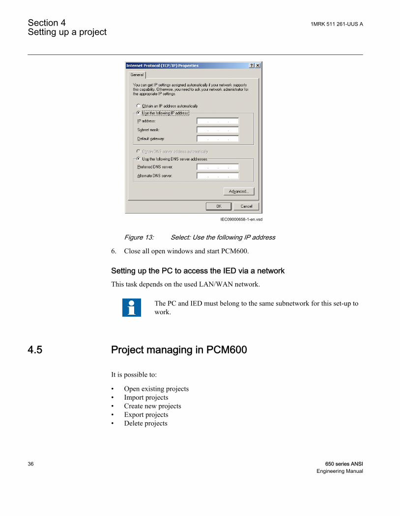
5. Select Use the following IP address and define IP address and Subnet mask if thefront port is used and if the IP address is not set to be obtained automatically bythe IED, see Figure 13. The IP address must be different from the IP addresschosen for the IED.
1MRK 511 261-UUS A Section 4Setting up a project
650 series ANSI 35Engineering Manual
IEC09000658-1-en.vsdIEC09000658 V1 EN
Figure 13: Select: Use the following IP address
6. Close all open windows and start PCM600.
Setting up the PC to access the IED via a networkThis task depends on the used LAN/WAN network.
The PC and IED must belong to the same subnetwork for this set-up towork.
4.5 Project managing in PCM600
It is possible to:
• Open existing projects• Import projects• Create new projects• Export projects• Delete projects
Section 4 1MRK 511 261-UUS ASetting up a project
36 650 series ANSIEngineering Manual
• Rename projects• Copy and paste projects• Migrate projects from one product version to another
It is possible to open projects created in previous versions of PCMto the current version, but the opposite is not possible.
Extensions of the exported project file is *.pcmp and those files are only used forexporting and importing the projects between PCM600s.
Creating a new projectProcedure
1. Select File and Open/Manage Project ... to see the projects that are currentlyavailable in the PCMDataBases.
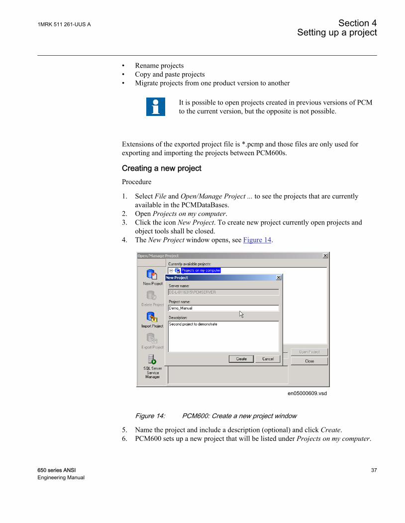
2. Open Projects on my computer.3. Click the icon New Project. To create new project currently open projects and
object tools shall be closed.4. The New Project window opens, see Figure 14.
en05000609.vsd
IEC05000609 V1 EN
Figure 14: PCM600: Create a new project window
5. Name the project and include a description (optional) and click Create.6. PCM600 sets up a new project that will be listed under Projects on my computer.
1MRK 511 261-UUS A Section 4Setting up a project
650 series ANSI 37Engineering Manual

4.6 Building a plant structure
The plant structure is used to identify each IED in its location within the substationorganization. It is a geographical image of the substation and the bays within thesubstation. The organization structure for the IEDs may differ from the structure of theprimary equipment in the substation. In PCM600 it is possible to set up a hierarchicalstructure of five levels for the IED identification.
Build up the plant structure according to the project requirements. PCM600 offersseveral levels to build the hierarchical order from Center down to the IEDs in a bay.
The following levels are available:
1. Project = Center2. Substation = Name of the substation3. Voltage Level = identifies to which grid type or part in the substation the IED
belongs to4. Bay = Bay within the voltage level5. IED = selection of the IED, which is used in the bay. Several IEDs are possible
within a bay, for example one control IED and two protection IEDs.
IEC08000365-2-en.vsdIEC08000365 V2 EN
Figure 15: PCM600: Set up a plant structure
Once a plant structure is built the name of each level in the structure should berenamed by the names/identifications used in the grid. Use the right mouse button tobuild the plant structure by selecting the elements from the context menu. Rename thelevel after insertion, using the Rename possibility or the Object Properties. Figure 15shows the start of a project with two IEDs placed but still not renamed.
Section 4 1MRK 511 261-UUS ASetting up a project
38 650 series ANSIEngineering Manual

The plant structure corresponds to the complete grid including theneeded IEDs.
Procedure to build a plant structure:
• Right-click the plant structure and select New and Create from Template ..., or• Right-click in the plant structure and select New, General and select one of the
elements IED Group or Substation.• Click View in the menu bar and select Object Types. Select the needed elements
and drag and drop them into the plant structure. Close the window if it does notclose automatically.
4.6.1 IEC 61850 naming conventions to identify an IEDThis section is only valid when the IEC 61850 standard is used for station buscommunication. According to the IEC 61850–6 clause 8.4, the SCL model allows twokinds of project designation in the object properties.
• A technical key is used on engineering drawings and for signal identifications.This is contained in the attribute name as identification of each object. If this valueis used as reference to an object, it is contained in an attribute name starting with astring denoting the reference target object type, and ending with the string Name.The technical key is used within SCL for referencing other objects. Observe thatname is a relative identification within a hierarchy of objects.
• A user oriented textual designation is contained in attribute desc. Attributes are notallowed to contain carriage return, line feed or tab characters. The semantics ofdesc shall also be relative within an object hierarchy.
PCM600 takes care of these two possibilities. The two possible signal designations areavailable per object in the object properties for all hierarchical levels beginning withthe station as the highest level.
The technical key is automatically generated based on the rules and type specificationsof IEC 61346 and the extended definitions done for substations by a technicalcommittee. The technical key is shown in the Object Properties under SCL TechnicalKey or Technical Key.
• The station level is predefined by "AA1", where 1 is the index.• The voltage level is predefined by "J1", where 1 is the index.• The bay level is predefined by "Q01", where 01 is the index.• The IED is predefined by "A1", where 1 is the index.
The predefined full path name of the technical key for the IED would be AA1J1Q01A1.
1MRK 511 261-UUS A Section 4Setting up a project
650 series ANSI 39Engineering Manual

For all practical engineering purposes (both towards the IED and towards the 61850engineering process), the user should keep the default SCL technical key. It is howeverpossible, due to for example company naming policies, to rename the SCL technicalkey for the station level, voltage level, bay level and IED level using the Objectproperties window as shown in Figure 16.
• The station level has been renamed as "DMSTAT"• The voltage level has been renamed as "C1"• The bay level has been renamed as "Q1"• The IED has been renamed as "SB1"
The renamed full path name of the technical key for the IED would beDMSTATC1Q1SB1.
IEC08000374.vsdIEC08000374 V1 EN
Figure 16: PCM600: IEC 61850 signal designation concept
Section 4 1MRK 511 261-UUS ASetting up a project
40 650 series ANSIEngineering Manual

4.7 Inserting an IED
The context menu or the Object Types view shows the available 650 series IEDspossible to insert, on the bay level in the plant structure, according to the installedconnectivity package.
On the bay level in the plant structure it is possible to:
• Insert an IED in Offline mode or in Online mode:• Online mode: When the IED is already connected to PCM600 and the
communication is established, PCM600 can read the configuration directlyfrom the physical IED. This is useful when an order specific IED is used.The order configuration is written to the IED at the factory and can beaccessed by PCM600. The housing type, the used overlay version for localHMI and the IO boards included in the IED will be read from the IED directly.
• Offline mode: When the physical IED is not available or not connected toPCM600 the engineering steps are done without any synchronization withthe IED. The offline configuration in PCM600 can be synchronized with thephysical IED at a later state by connecting the IED to PCM600.
It is possible to judge whether the inserted IED is in offline modeor online mode from the plant structure. A red color cross beforethe IED symbol indicates the offline mode as shown in Figure 17.
IEC09000361-1-en.vsdIEC09000361 V1 EN
Figure 17: Plant structure showing IED TR_421 in online mode and IEDTR_521 in offline mode
• Import a template IED available in the template library as a *.pcmt file.• Import a configured IED available as a *.pcmi file.
Inserting an IED in online modeFor setting up an IED online, the IED must be connected to PCM600.
1MRK 511 261-UUS A Section 4Setting up a project
650 series ANSI 41Engineering Manual

Procedure
1. Right-click the Bay and select New and Sub-Transmission IEDs.2. Select the IED type to insert.
It is also possible to drag an IED from the Object Types window tothe Bay level.
3. Select the Online Configuration mode, see Figure 18.
IEC09000660-1-en.vsdIEC09000660 V1 EN
Figure 18: PCM600: Configuration mode selection wizard
4. Select the IED Communication protocol, see Figure 19.
Section 4 1MRK 511 261-UUS ASetting up a project
42 650 series ANSIEngineering Manual

IEC09000661-1-en.vsdIEC09000661 V1 EN
Figure 19: PCM600: Communication protocol selection wizard
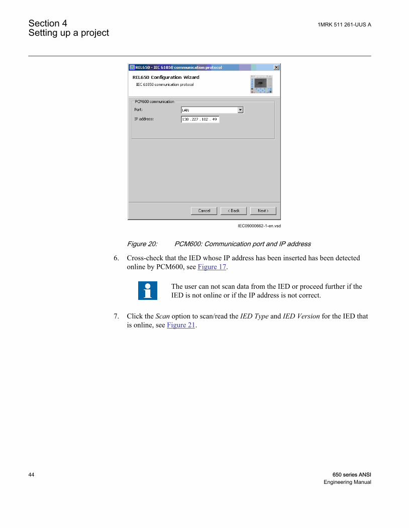
5. Select the port and insert the IP address of the physical IED to configure, seeFigure 20.
1MRK 511 261-UUS A Section 4Setting up a project
650 series ANSI 43Engineering Manual
IEC09000662-1-en.vsdIEC09000662 V1 EN
Figure 20: PCM600: Communication port and IP address
6. Cross-check that the IED whose IP address has been inserted has been detectedonline by PCM600, see Figure 17.
The user can not scan data from the IED or proceed further if theIED is not online or if the IP address is not correct.
7. Click the Scan option to scan/read the IED Type and IED Version for the IED thatis online, see Figure 21.
Section 4 1MRK 511 261-UUS ASetting up a project
44 650 series ANSIEngineering Manual

IEC09000663-2-en.vsdIEC09000663 V2 EN
Figure 21: PCM600: IED Version detection
8. Click next to open the Housing Selection Page and select the housing and displaytype of the IED, see Figure 22
1MRK 511 261-UUS A Section 4Setting up a project
650 series ANSI 45Engineering Manual

IEC09000682-1-en.vsdIEC09000682 V1 EN
Figure 22: PCM600: IED housing and display type detection
9. The Setup Complete Page dialog shows the summary of theIED Type, IED Version, IP Address of IED and Order Number,see Figure 23. It is possible to Cancel the insertion or confirm the configurationand do the insertion with Finish
Section 4 1MRK 511 261-UUS ASetting up a project
46 650 series ANSIEngineering Manual

IEC09000664_3_en.vsdIEC09000664 V3 EN
Figure 23: PCM600: IED Setup completion wizard
It is not possible to go back and do any modifications in the setupcomplete page. If an error is detected, the insertion has to be canceledand the IED has to be inserted again.
When the online configuration is completed, it is advised to read theconfiguration from the IED to ensure that the IED object in PCM600has the same configuration data as the physical IED.
1MRK 511 261-UUS A Section 4Setting up a project
650 series ANSI 47Engineering Manual

Inserting an IED in offline modeWorking in offline mode has an advantage compared to online mode that one can startpreparing configuration even though IED is not available. Setting up an IED in offlinemode is almost similar to that of an online mode; however with offline mode it is notnecessary to type the correct IP address in the Communication port and IP address dialog.
The version information and order specific file needs to be selected, see Figure 24. Theorder specific file is delivered in a order confirmation E-mail. If no order specific file isavailable then select the No Order Specific File option, see Figure 25.
IEC09000665 V4 EN
Figure 24: PCM600: IED Version selection
Section 4 1MRK 511 261-UUS ASetting up a project
48 650 series ANSIEngineering Manual

IEC09000681 V2 EN
Figure 25: PCM600: IED Order code selection
Change hardware configuration after IED is insertedIn hardware tool it is possible to change the hardware configuration of the IED after itis inserted, for example if wrong selections were made in off line mode when nolicense file was used.
In 650 series version 1.2.1 some hardware selections are possible to make even if theyare not possible to order. It will not be possible to download an invalid hardwareconfiguration to the IED. The tool will stop and an error message “License file is notmatching” will be shown.
1MRK 511 261-UUS A Section 4Setting up a project
650 series ANSI 49Engineering Manual

Hardware selections that are not available to order:
Housing variants: 6U ½ 19” rack casing
Display types: IEC 6U ½ 19”, Basic
ANSI 6U ½ 19”, Basic
Card Types COM02
IEC12000178 V1 EN
Figure 26: Hardware tool view of the IED
Inserting an IED from the template libraryAn IED in the plant structure can be exported as a template (*.pcmt). The user canbuild up a template library with all the exported IED templates. It is possible to insertan IED from the template library to create a new IED in the plant structure. Change theIP address, the name and the technical key that corresponds to the physical IED after atemplate IED has been imported.
A template IED can only be inserted when the bay is selected in theplant structure.
Section 4 1MRK 511 261-UUS ASetting up a project
50 650 series ANSIEngineering Manual

Procedure to insert a template IED
1. Right-click the Bay in the plant structure.2. Select New and Create from Template ... to open the Create New Object from
Template window, see Figure 27.
IEC08000366.vsdIEC08000366 V1 EN
Figure 27: PCM600: Selecting IED from template library
3. Select the IED from the list of available IEDs.4. Click the icon in the right column of the list of available templates to open the
Template Properties. Verify the template information, see Figure 28 and clickClose to close the window.
1MRK 511 261-UUS A Section 4Setting up a project
650 series ANSI 51Engineering Manual

IEC08000367.vsdIEC08000367 V1 EN
Figure 28: PCM600: IED Template Properties
5. Click Delete Template to delete the template, click Import Template to import atemplate from the selection window or click Create to insert the selected IED tothe bay, see Figure 27.
It is possible to insert more than one IED from the Create NewObject from Template window and the selection window remainsopen until the user clicks Close.
Inserting a configured IED in 650 seriesConfigured IEDs in 650 series in PCM600 are available as *.pcmi files and include allinformation that is related to the IED object in PCM600. The configured IEDs in 650series is bound to a specific hardware configuration. Configured IEDs in 650 series areavailable on the Connpack DVD as .pcmi files under the file named User documentation.
Two alternatives to insert configured IEDs in 650 series:
• Use the configured IEDs in 650 series that has been ordered together with the IED.• Create an own configuration, export the configuration as *.pcmi file and use it to
configure other IEDs.
Section 4 1MRK 511 261-UUS ASetting up a project
52 650 series ANSIEngineering Manual
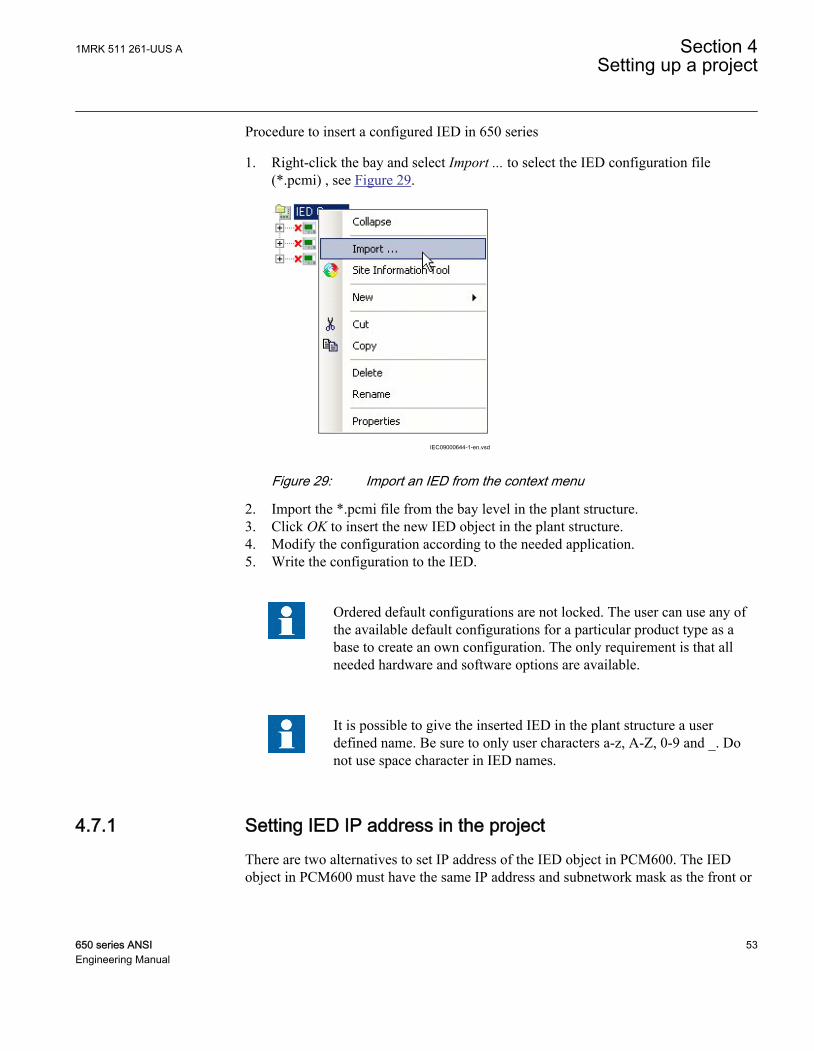
Procedure to insert a configured IED in 650 series
1. Right-click the bay and select Import ... to select the IED configuration file(*.pcmi) , see Figure 29.
IEC09000644-1-en.vsd
IEC09000644 V1 EN
Figure 29: Import an IED from the context menu
2. Import the *.pcmi file from the bay level in the plant structure.3. Click OK to insert the new IED object in the plant structure.4. Modify the configuration according to the needed application.5. Write the configuration to the IED.
Ordered default configurations are not locked. The user can use any ofthe available default configurations for a particular product type as abase to create an own configuration. The only requirement is that allneeded hardware and software options are available.
It is possible to give the inserted IED in the plant structure a userdefined name. Be sure to only user characters a-z, A-Z, 0-9 and _. Donot use space character in IED names.
4.7.1 Setting IED IP address in the projectThere are two alternatives to set IP address of the IED object in PCM600. The IEDobject in PCM600 must have the same IP address and subnetwork mask as the front or
1MRK 511 261-UUS A Section 4Setting up a project
650 series ANSI 53Engineering Manual

rear port on the physical IED to which the PC is connected. The IP address of thephysical IEDs front and rear port can not be set from PCM600 but only from LHMI.
• Via the first window of the wizard when including a new IED in a project, seeFigure 30.
IEC09000662-1-en.vsdIEC09000662 V1 EN
Figure 30: Alternative 1: IP address via first Wizard window
• Via the IP address property of the IED in the Object Properties window, seeFigure 31.
Section 4 1MRK 511 261-UUS ASetting up a project
54 650 series ANSIEngineering Manual

IEC08000121-2-en.vsdIEC08000121 V2 EN
Figure 31: Alternative 2: IP address via IED Object Properties window
Procedure
1. Select the IED to enter the IP address.2. Open the Object Properties window.3. Place the cursor in the IP address row and enter the IP address.
The used alternative depends on the time at which the IP address is available.
1MRK 511 261-UUS A Section 4Setting up a project
650 series ANSI 55Engineering Manual

56

Section 5 Protection and control engineering
5.1 Creating an application configuration with ACT
5.1.1 OverviewACT is used to create the application configuration for an IED. The applicationconfiguration is built up with function blocks.
Function blocks are dedicated for different functionality, for example:
• Preprocessing blocks• Control related functions• Protection related functions• Monitoring functions• Communication
For detailed information about function blocks see the technical manualand the application manual.
Some function blocks are mapped as logical nodes according to the IEC 61850standard. See the IEC 61850 communication protocol manual for detailed information.Other function blocks are not mapped as logical nodes, for example:
• Logical gates• Timers
The basic general features of the Application configuration tool ACT:
• Organization of an application configuration• Organize an application configuration into a number of logical parts
(MainApplication).• Organize a MainApplication over a number of pages.
• Features to program an application configuration:• Insert function blocks, make connections and create variables.• Include the hardware IO channels directly in the application configuration.• Set function blocks and signal visibility to SMT and PST.
1MRK 511 261-UUS A Section 5Protection and control engineering
650 series ANSI 57Engineering Manual
SMT is not supporting signals of integer type or groupsignals. So, even if these types of signals are set as visible forSMT, they will not be shown in SMT.
• Document the application configuration, for example to make printouts.• Test the application configuration online.
The function block signal values are updated in the onlinedebug mode only if the function is enabled.
• Save application configurations as templates in an application library toreuse them in other IEDs.
• Validate the application configuration during the configuration process ondemand and while writing the application configuration to the IED.
For instructions on how to perform the different tasks in PCM600, seePCM600 online help.
5.1.2 Function blocks• Function blocks are the main elements of an application configuration. They are
designed for a various number of functions and organized in type groups. Thedifferent function block types are shown in the Object Types View. Figure 32presents an overview of the main parts that are relevant for function blocks.
• Set user defined names for function blocks and signals marked with blue text.
Signals that have a user defined name created in ACT, will only bevisible in PST if the IED configuration is written to the IED andread back to PCM600. Otherwise the default signal name is shownin PST.
Do not use other characters than a-z, A-Z, 0-9 and _ when settinguser defined names for signals and function blocks, since othercharacters might not display properly in local HMI. Also avoidusing space character.
• Set IEC 61850, ANSI or IEC 60617 symbol standard.• Set IEC or/and ANSI naming style.• Lock function blocks.
Section 5 1MRK 511 261-UUS AProtection and control engineering
58 650 series ANSIEngineering Manual

• Set visibility for execution order, cycle time and instance number.• Manage signals, for example hide, show and rearrange.• Invert Boolean inputs and Boolean outputs.
Mandatory signals must be connected.
Function blocks with disconnected outputs are not executing and hencemay show improper values on the outputs.
1MRK 511 261-UUS A Section 5Protection and control engineering
650 series ANSI 59Engineering Manual

IEC08000258.vsd
1 3 7 8 9
1716
121110
2 5 6
151413
4
IEC08000258 V1 EN
Figure 32: ACT: Function block overview
1 Connection(s)
2 User defined function block name
3 Function block, selected (red)
4 Mandatory signal (indicated by a red triangle if not connected)
5 Function block name
6 Function block, locked (red)
7 ANSI symbol
8 Inverted output
9 Hardware, binary output channel
10 Hardware, analog input channel
11 User defined signal name
12 Hardware, binary input channel
13 Execution order
14 Cycle time
15 Instance number
16 Inverted input
17 Signal description note
5.1.3 Signals and signal managementA function block has set of input and output signals. The placement of the signals for afunction block is from left to right. Input signals are placed on the left side and outputsignals are placed on the right side.
Section 5 1MRK 511 261-UUS AProtection and control engineering
60 650 series ANSIEngineering Manual
A function block can contain more signals than needed in that application part. Asignal that is not used in a particular application is possible to hide in the functionblock view in ACT.
Signals are located on both sides of the middle position up and down. When there isspace left, move some signals up or down for a better visibility and connection routing.
Boolean input and output signals may need to be inverted to fulfill the logic. ACTsupports to add the inversion logic to a binary signal.
The input signal on glue logic function blocks can only be inverted if aglue logic function block with lower execution order in the same cycletime is available. Similar, the output signal can only be inverted if aglue logic function block with higher execution order in the same cycletime is available. Up to two input signals and two output signals can beinverted for glue logic blocks in the same cycle time.
Even though current is injected to the IED and the IED is connected toPCM600 in online mode, the signal value in ACT is shown as zero.
All not mandatory input signals have a default value that will be used when not connected.
5.1.4 Function block execution parametersThree function block execution parameters have influence on the runtime execution ofthe function block within the application configuration.
• Execution order• Cycle time• Instance number
Each time a new function block is selected these parameters have to be selected. Infixed mode user selects parameters from the drop down lists in ACT. In automaticmode best suitable instance is selected automatically. Depending on the function blocktype not all three parameters are selectable. The cycle time may be predefined to onevalue. The instance number is a counter for the total possible number of functionblocks of that type used within an application configuration.
The Execution Order and Instance Number are a combination that is predefined withina product. It is possible to select a pair out of the list. Figure 33 shows an example howthe drop down list could look like.
1MRK 511 261-UUS A Section 5Protection and control engineering
650 series ANSI 61Engineering Manual
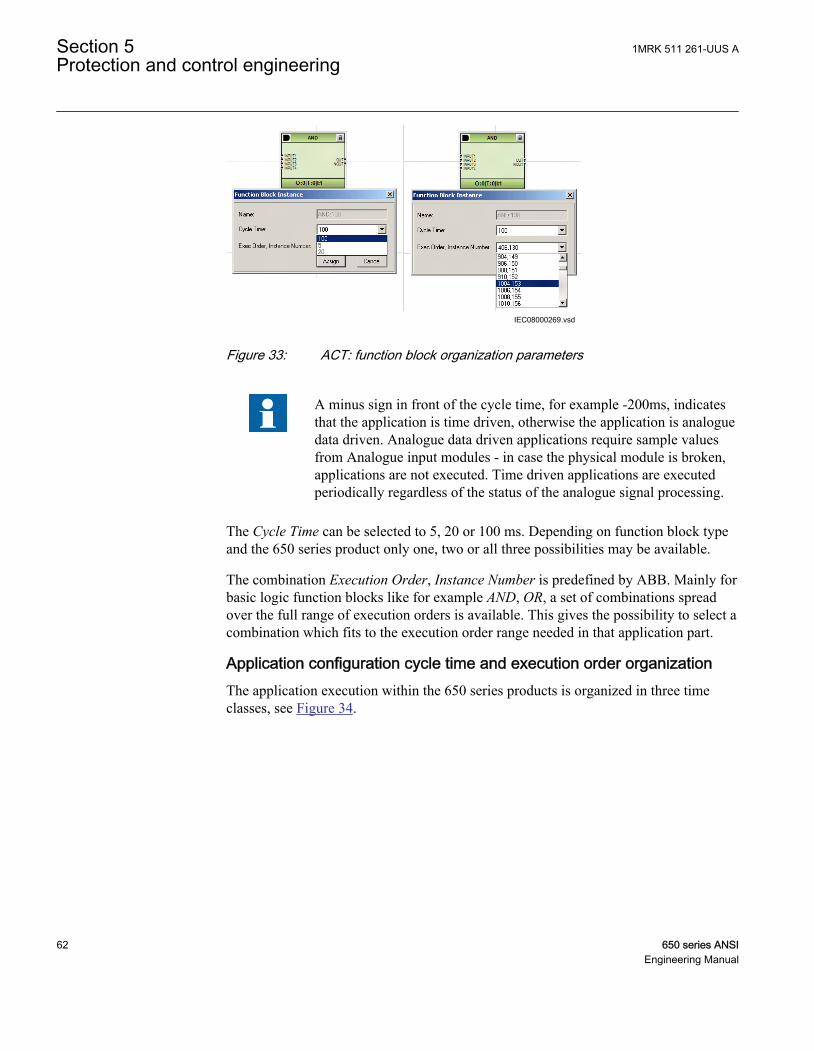
IEC08000269.vsdIEC08000269 V1 EN
Figure 33: ACT: function block organization parameters
A minus sign in front of the cycle time, for example -200ms, indicatesthat the application is time driven, otherwise the application is analoguedata driven. Analogue data driven applications require sample valuesfrom Analogue input modules - in case the physical module is broken,applications are not executed. Time driven applications are executedperiodically regardless of the status of the analogue signal processing.
The Cycle Time can be selected to 5, 20 or 100 ms. Depending on function block typeand the 650 series product only one, two or all three possibilities may be available.
The combination Execution Order, Instance Number is predefined by ABB. Mainly forbasic logic function blocks like for example AND, OR, a set of combinations spreadover the full range of execution orders is available. This gives the possibility to select acombination which fits to the execution order range needed in that application part.
Application configuration cycle time and execution order organizationThe application execution within the 650 series products is organized in three timeclasses, see Figure 34.
Section 5 1MRK 511 261-UUS AProtection and control engineering
62 650 series ANSIEngineering Manual
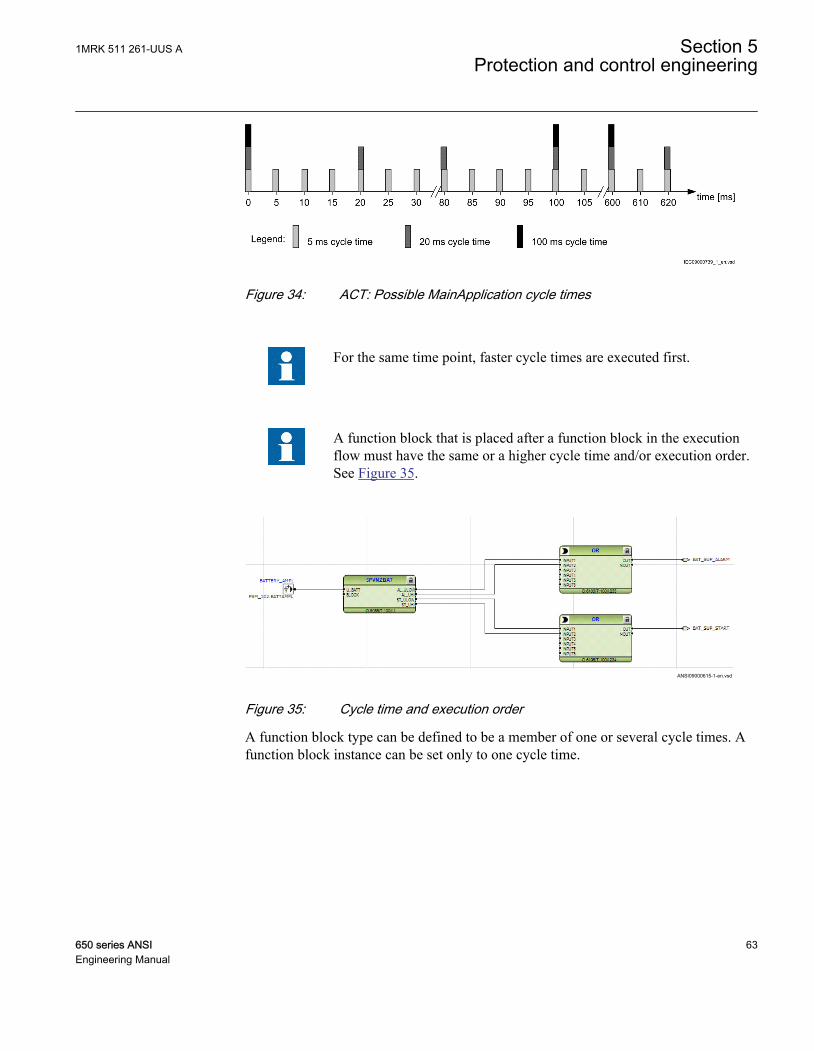
IEC09000739 V1 EN
Figure 34: ACT: Possible MainApplication cycle times
For the same time point, faster cycle times are executed first.
A function block that is placed after a function block in the executionflow must have the same or a higher cycle time and/or execution order.See Figure 35.
ANSI09000615-1-en.vsd
ANSI09000615 V1 EN
Figure 35: Cycle time and execution order
A function block type can be defined to be a member of one or several cycle times. Afunction block instance can be set only to one cycle time.
1MRK 511 261-UUS A Section 5Protection and control engineering
650 series ANSI 63Engineering Manual

IEC08000271.vsd
Execution ordergroup 1
Execution ordergroup 2
Execution ordergroup 3
Execution Flow
IEC08000271 V1 EN
Figure 36: ACT: Concept of Execution order sequence
In the conceptual MainApplication example in Figure 36, the execution order of themain function block in the execution order group 2 defines the execution orders neededin group 1 and 3. The preceding logic done with function blocks in group 1 must havea lower execution order than the ones in group 2. The following function blocks ingroup 3 must have a higher execution order than the main function block in group 2.
5.1.5 Configuration parametersConfiguration parameters are found in the parameter setting tool. For example, theSMAI function block has to be configured to support AC-current values or AC-voltagevalues.
5.1.6 Connections and variablesA connection is the link or "wire" between function block outputs and inputs.
Rules and methods to do connections:
• Drag a line between two signals.• Link two signals by using variables.
It is possible to search and replace variable names in ACT.
Connection validationA connection is only useful and possible between two signals of the same data type,see Figure 37.
Section 5 1MRK 511 261-UUS AProtection and control engineering
64 650 series ANSIEngineering Manual
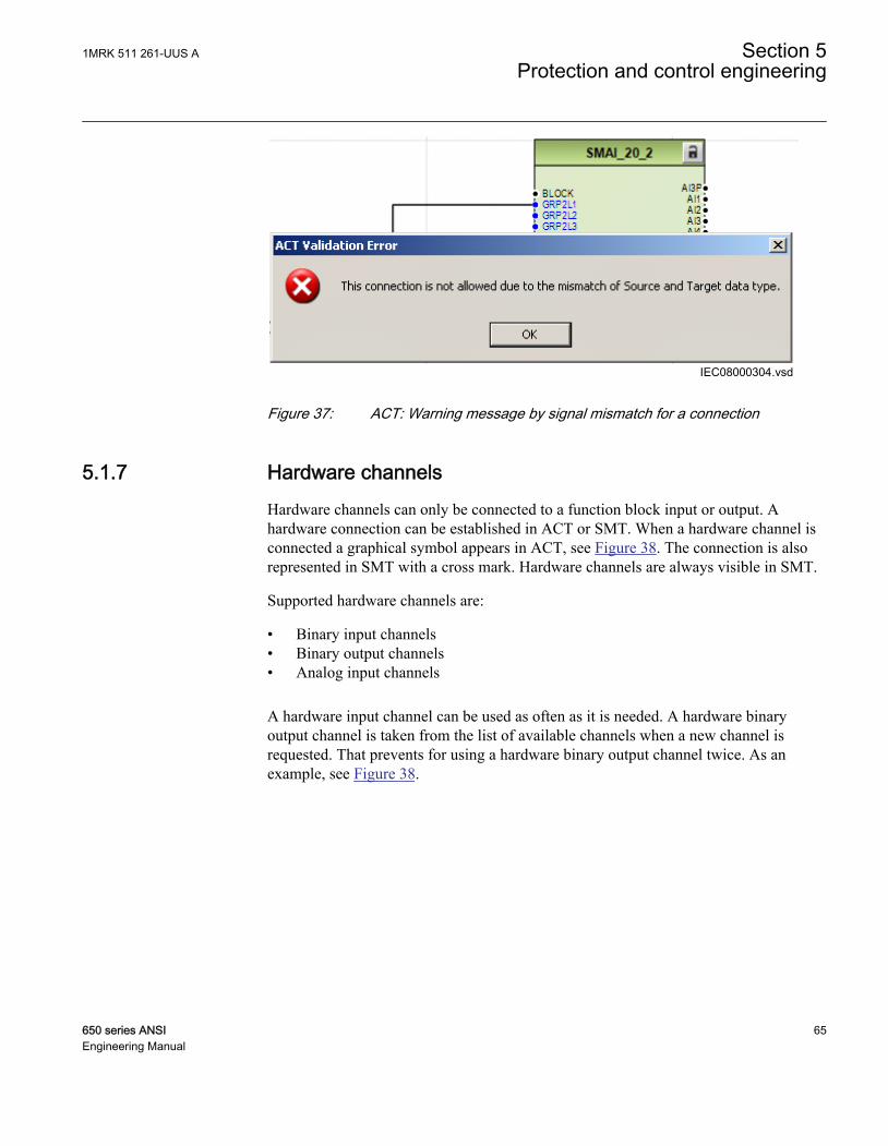
IEC08000304.vsdIEC08000304 V1 EN
Figure 37: ACT: Warning message by signal mismatch for a connection
5.1.7 Hardware channelsHardware channels can only be connected to a function block input or output. Ahardware connection can be established in ACT or SMT. When a hardware channel isconnected a graphical symbol appears in ACT, see Figure 38. The connection is alsorepresented in SMT with a cross mark. Hardware channels are always visible in SMT.
Supported hardware channels are:
• Binary input channels• Binary output channels• Analog input channels
A hardware input channel can be used as often as it is needed. A hardware binaryoutput channel is taken from the list of available channels when a new channel isrequested. That prevents for using a hardware binary output channel twice. As anexample, see Figure 38.
1MRK 511 261-UUS A Section 5Protection and control engineering
650 series ANSI 65Engineering Manual

IEC09000613-2-en.vsdIEC09000613 V2 EN
Figure 38: ACT: HW signal channels
5.1.8 ValidationValidation checks the application configuration on errors about the rules andrestrictions defined for doing a MainApplication on three levels.
• During creating the logic while doing a connection or placing a function block.• On demand by starting the validation.• When writing the application configuration into the IED.
Validation when creating the application configurationValidation is made when creating the application configuration, for example:
Section 5 1MRK 511 261-UUS AProtection and control engineering
66 650 series ANSIEngineering Manual

• A connection between two input signals or two output signals is not possible.• A connection between two different data types is not possible, for example a
binary output to an analog input.
Validation on demandTo check the validity of an application configuration, click the 'Validate Configuration'icon in the toolbar. ACT will check the application configuration for formalcorrectness. Found problems are qualified in:
• Warnings, marked by a yellow warning icon• Example: A variable connected to an output signal that is not connected.• Example: If the user connects output from higher execution order function to
inputs of lower execution order function.• Errors, marked by a red circle with a cross
• Example: A mandatory input signal that is not connected.
Warnings will not prevent writing to the IED. Errors have to be corrected beforewriting the application configuration to the IED. An application configuration can besaved and ACT can be closed with open errors, but not written to the IED, see Figure39.
These problems are listed in the Output View under the Tab Application Configuration.A double-click in the error or warning row will navigate to theMainApplication>Page>Area where the problems are identified.
IEC09000614_2_en.vsdIEC09000614 V2 EN
Figure 39: ACT: Validation on demand
1MRK 511 261-UUS A Section 5Protection and control engineering
650 series ANSI 67Engineering Manual

Validation when writing to the IEDWhen writing the application configuration to the IED an automatic validation isperformed. The validation is the same as the manually demanded validation. Errorswill abort the writing.
5.2 Setting configuration and setting parameters in PST
Configuration parameters and settings parameters are changeable either from LHMI orfrom PST in PCM600.
Note that the some parameters are only visible in PST and some areonly visible on LHMI.
A common write from PCM600 to the IED, where parameters arechanged in PST, will overwrite any parameter changes made locallyfrom LHMI.
To export parameters from PST, both XRIO and CSV formats aresupported.
Do not make PST read/write operation to IED when disturbancerecorder is storing data since that causes PCM600 to report that the IEDis offline or having communication problems.
All variables listed and shown in the parameter list can be sorted into two groups:
• Configuration parameter or• Setting parameter
Configuration parameterA configuration parameter specifies an operation mode of an application function or ofthe IED. These are basic configurations, which are normally configured only once andthen settled. The IED configures itself at start-up according to the given configurationparameter values.
Section 5 1MRK 511 261-UUS AProtection and control engineering
68 650 series ANSIEngineering Manual
Setting parameterA setting parameter (short form only “setting”) is a parameter that can be changed inthe IED at runtime.
Setting groupNearly all settings used by the IED for the protection application functions areorganized in a group of settings. Up to four setting groups can be configured withdifferent values. The IED supports the selection of a setting group at runtime.
IED parameters organizationThe organization of the parameters in a tree structure is visible in the plant structure byexpanding the setting tree. For each function, the parameters are organized in basic andadvanced groups. The advanced settings are used for application optimization. Duringa common write both the basic and advanced settings are written to the IED.
5.3 Connecting signals in SMT
SMT is used to do cross references, see Figure 40:
• between physical IO signals and function blocks.• for the GOOSE engineering.
1MRK 511 261-UUS A Section 5Protection and control engineering
650 series ANSI 69Engineering Manual

IEC08000173_2_en.vsd
BIO
BIO
TRM
FBs
GOOSE InputsGOOSE FBs for
binary and analog data, interlocking communication
and voltage control
IEC 61850
SMAI
FBs
IEC08000173 V2 EN
Figure 40: SMT: Operation principles
A binary input channel can be connected to one or several function block inputs, seeFigure 41. If a binary input channel is connected to several different function blocks inACT, the connection will appear as glue logic in SMT.
A binary output channel can only be activated from one function block output. If itshould be activated from more than one function block output, glue logic has to beused. Glue logic means inserting a logical gate (OR and AND blocks) between thefunction blocks and the binary output channel. This can be engineered in SMT.
Connections made in SMT are automatically shown in ACT.Connections made in ACT are automatically shown in SMT.
Section 5 1MRK 511 261-UUS AProtection and control engineering
70 650 series ANSIEngineering Manual
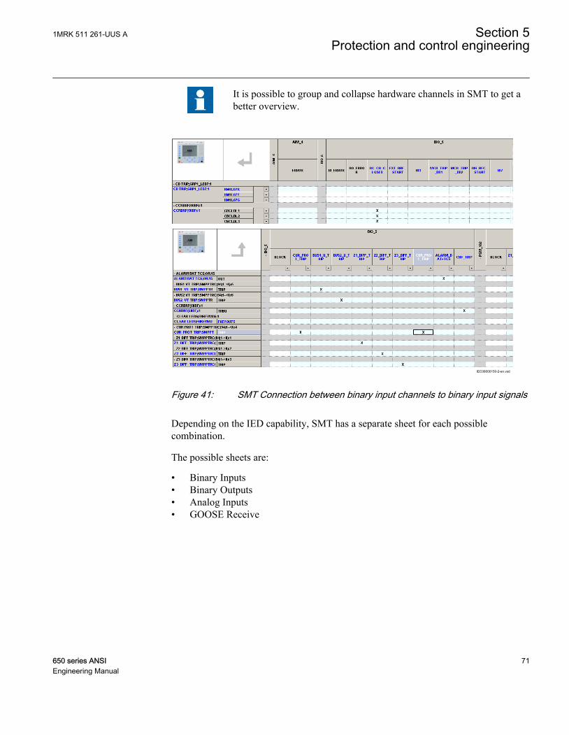
It is possible to group and collapse hardware channels in SMT to get abetter overview.
IEC08000150-2-en.vsd
IEC08000150 V2 EN
Figure 41: SMT Connection between binary input channels to binary input signals
Depending on the IED capability, SMT has a separate sheet for each possiblecombination.
The possible sheets are:
• Binary Inputs• Binary Outputs• Analog Inputs• GOOSE Receive
1MRK 511 261-UUS A Section 5Protection and control engineering
650 series ANSI 71Engineering Manual

72
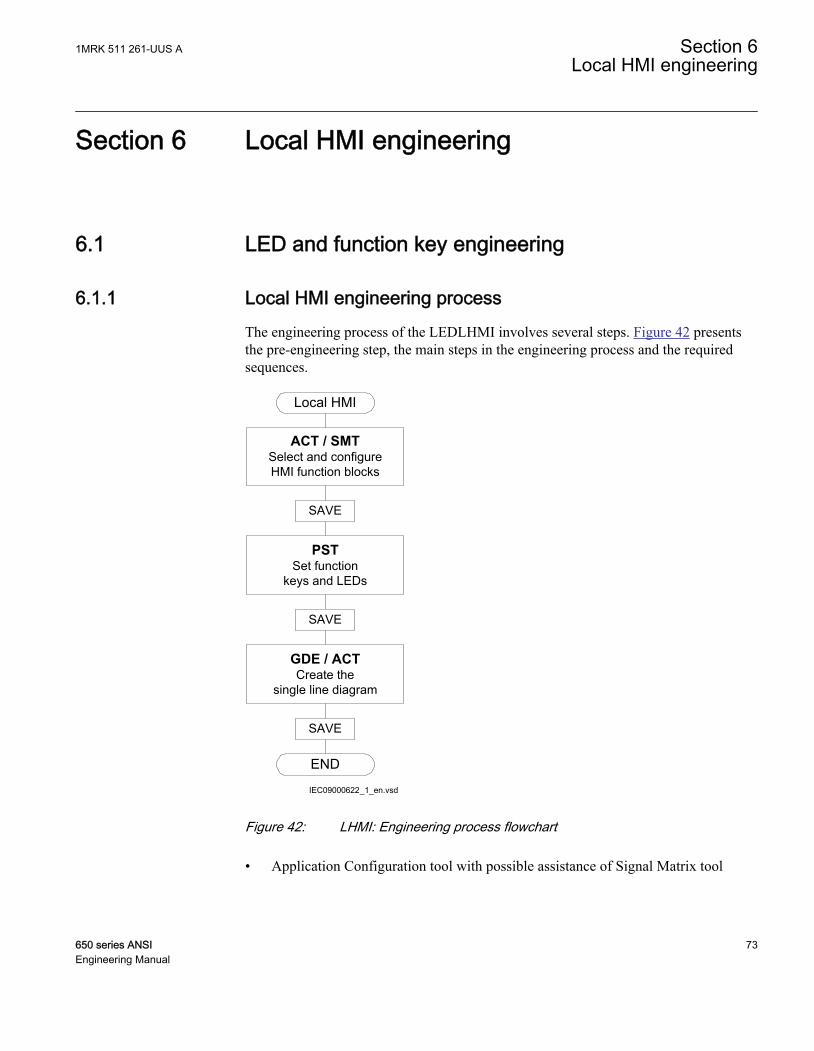
Section 6 Local HMI engineering
6.1 LED and function key engineering
6.1.1 Local HMI engineering processThe engineering process of the LEDLHMI involves several steps. Figure 42 presentsthe pre-engineering step, the main steps in the engineering process and the requiredsequences.
IEC09000622_1_en.vsd
Local HMI
ACT / SMTSelect and configure HMI function blocks
PSTSet function
keys and LEDs
END
SAVE
SAVE
GDE / ACT Create the
single line diagram
SAVE
IEC09000622 V1 EN
Figure 42: LHMI: Engineering process flowchart
• Application Configuration tool with possible assistance of Signal Matrix tool
1MRK 511 261-UUS A Section 6Local HMI engineering
650 series ANSI 73Engineering Manual

• To use the function keys and LEDs on LHMI it is needed to insert thecorresponding special function blocks for these operation element groups.
• The function blocks for the LEDs are organized as single function block perLED but indexed to the group identification, for example GRP1_LED3(indication LED 3 in virtual LED group 1).
• The function blocks for LHMI are visible by default for Parameter Setting tool.• Use Application Configuration tool to connect start and trip signals from
application functions to LED function blocks.• Parameter Setting tool
• The operation mode of the function keys and the LEDs is defined inParameter Setting tool.
• The presented text labels on the LCD for LHMI keys and LEDs.• Graphical Display Editor with assistance of Application Configuration tool, for
example• to make the single line diagram of the primary process part.• to make the dynamic links for the apparatus.• to make the dynamic links for measurements.
Application Configuration tool and local HMI function blocksA set of special function blocks is available for all the operation element groups onLHMI.
See the technical manual for more information about function blocks.
List of LHMI function blocks that are available in Application Configuration tool:
• LHMICTRL• FNKEYMD1 to FNKEYMD5• LEDGEN• GRP1_LED1 to GRP1_LED15• GRP2_LED1 to GRP2_LED15• GRP3_LED1 to GRP3_LED15
The function blocks for the LEDs are organized in function blocks per LED. They canbe placed close to the logic where the information per LED is built in ApplicationConfiguration tool.
Figure 6 describes the basic LHMI and the operation element groups. These are the 15LEDs and their belonging text elements on the LCD [A]. They are operated by the keys[a] and [b].
Section 6 1MRK 511 261-UUS ALocal HMI engineering
74 650 series ANSIEngineering Manual

The other group is the five function keys with their IEDs and the corresponding textelements on the LCD [B].
Function block LEDGEN
• Handles an external acknowledge signal as source to acknowledge the LEDs.• Generates an additional pulse for general purposes whenever the LEDs are
acknowledged by the operator.• Generates a pulse whenever a new LED signal occurs. It may be used to trigger an
acoustical alarm.• Handles the timer tReset and tMax for the LED operation mode 'LatchedReset-S'.
Function block GRP1_LED1 to GRP3_LED15
• The 15 LEDs on the right side of the LCD can indicate in total 45 alarms,warnings or other signals to the operator. They are organized in three groups 1 to 3.
• Each signal group belongs to one function block.• Each LED illuminates in one of the three colors: RED, YELLOW or GREEN.• The organization of flashing, acknowledgment and group selection is done directly
between the function blocks and the basic LHMI keys, the 'Multifunction' key [a]to toggle between the three groups or the 'Clear' key [b] to acknowledge or resetthe LEDs.
• Only the programming of the signals is needed for the LEDs.• The operation mode of the LEDs is defined in Parameter Setting tool.
Function block FNKEYMD1 to 5
• Every function key has an own FNKEYMD function block.• The 5 function keys on the left side of the LCD [B] can be used to process demands.• The function block handles the signal for the LED included in the key as input signals.• The LED signal of the key is independent of the key function and must be
programed to process demands.• The function block handles the operators command when the key is pressed as
output signal.• The functions are activated whenever a key is pressed the first time. The
corresponding text elements for the five keys appear on the left side of the LCD.No execution of the function is done. So the first push is used to activate thepresentation only.
• The next key push is handled as activate function and the output signal of thefunction block is set.
• The operation mode of the function key is defined in Parameter Setting tool (pulse,toggle).
1MRK 511 261-UUS A Section 6Local HMI engineering
650 series ANSI 75Engineering Manual

Parameter Setting tool and function block configurationThe operation mode of the function keys and the LEDs must be defined per key andLED in Parameter Setting tool.
The function key can operate as:
• Pulsed signal• Each push forces a pulse of a configured time.• The pulse time can be set in Parameter Setting tool.• The default pulse time is 200 ms.
• Toggle signal• Each push changes the state of the signal: OFF-ON-OFF-ON-OFF...• The default position after power up or reset is OFF.
• Menu shortcut• When pressing a key configured for that purpose, the function key panel is
hidden and LHMI opens directly in the configured menu.
IEC09000656-1-en.vsdIEC09000656 V1 EN
Figure 43: LHMI: Function key operation mode
The LEDs have a number of different operation modes, see Figure 44:
• General definitions• Each LED can illuminate in one of three colors: RED, YELLOW, GREEN.• Only one color is illuminated at a time.• The priority for illumination and the color is linked.
Section 6 1MRK 511 261-UUS ALocal HMI engineering
76 650 series ANSIEngineering Manual

• Prio 1 = RED• Prio 2 = YELLOW• Prio 3 = GREEN• When RED and YELLOW are ON at the same time, the LED will
illuminate in RED.• The operator's acknowledge for the LED signals is done for all three signals
(RED, YELLOW, GREEN) of the LED.• A reset of the LLEDs operates also on all three signals of the LEDs.
• Follow-S• The LED illumination follows the status of the signal. The LED illuminates
steady (S).• Follow-F
• The LED illumination follows the status of the signal. The LED illuminatesflashing (F).
• LatchedAck-F-S• The LED latches the signal change OFF-ON and flashes (F) until it is
acknowledged.• When the signal is still ON at the time the signal is acknowledged the LED
changes to steady (S) mode.• When the signal has already changed to OFF before the time it is
acknowledged, the LED turns to OFF.• LatchedAck-S-F
• The same as LatchedAck-F-S but the LED starts with steady state andflashes after acknowledgment.
• LatchedColl-S• The LED illuminates in all cases in steady mode only• The LED latches a signal change from OFF-ON until it is acknowledged by
the operator.• The LED stays in steady mode when it is reset and the signal is still in ON
state.• The LED is OFF only after the signal has changed to OFF state AND it is
reset by the operator via 'Clear' operation.• LatchedReset-S
• This mode is used for all LEDs that are used to indicate a disturbance. TheLEDs will stay in the last state after the disturbance run time until they arereset after a defined time.
• The timers are set in Parameter Setting tool in the function block LEDGEN.
1MRK 511 261-UUS A Section 6Local HMI engineering
650 series ANSI 77Engineering Manual
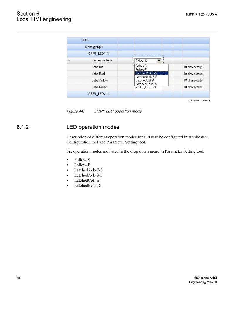
IEC09000657-1-en.vsdIEC09000657 V1 EN
Figure 44: LHMI: LED operation mode
6.1.2 LED operation modesDescription of different operation modes for LEDs to be configured in ApplicationConfiguration tool and Parameter Setting tool.
Six operation modes are listed in the drop down menu in Parameter Setting tool.
• Follow-S• Follow-F• LatchedAck-F-S• LatchedAck-S-F• LatchedColl-S• LatchedReset-S
Section 6 1MRK 511 261-UUS ALocal HMI engineering
78 650 series ANSIEngineering Manual

LED operation mode Follow-S
IEC08000395.vsd
= Steady = FlashIllumination =>
RYG
RYG
Sig
nals
LED
IEC08000395 V1 EN
Figure 45: LHMI: LED operation mode Follow-S
Monitoring a signal with a LED is a simple mode, where the LED follows the signalstate. More than one signal per LED can be used when applicable. See Figure 45 forthe valid priority rules. The LED illuminates always in steady state.
LED operation mode Follow-F
IEC08000396.vsd
= Steady = FlashIllumination =>
RYG
RYG
Sig
nals
LED
IEC08000396 V1 EN
Figure 46: LHMI: LED operation mode Follow-F
This is the same mode as Follow-S but the LED illuminates flashing, see Figure 46.This mode may be used to indicate that a tap changer or Petersen coil is moving.
1MRK 511 261-UUS A Section 6Local HMI engineering
650 series ANSI 79Engineering Manual
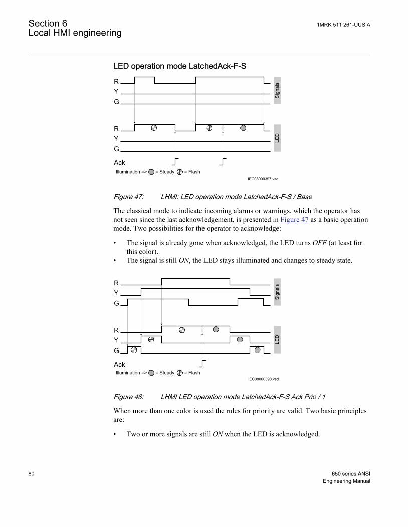
LED operation mode LatchedAck-F-S
IEC08000397.vsd
RYG
RYG
Sig
nals
LED
Ack= Steady = FlashIllumination =>
IEC08000397 V1 EN
Figure 47: LHMI: LED operation mode LatchedAck-F-S / Base
The classical mode to indicate incoming alarms or warnings, which the operator hasnot seen since the last acknowledgement, is presented in Figure 47 as a basic operationmode. Two possibilities for the operator to acknowledge:
• The signal is already gone when acknowledged, the LED turns OFF (at least forthis color).
• The signal is still ON, the LED stays illuminated and changes to steady state.
IEC08000398.vsd= Steady = FlashIllumination =>
RYG
RYG
Sig
nals
LED
Ack
IEC08000398 V1 EN
Figure 48: LHMI LED operation mode LatchedAck-F-S Ack Prio / 1
When more than one color is used the rules for priority are valid. Two basic principlesare:
• Two or more signals are still ON when the LED is acknowledged.
Section 6 1MRK 511 261-UUS ALocal HMI engineering
80 650 series ANSIEngineering Manual
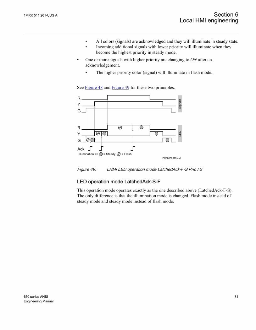
• All colors (signals) are acknowledged and they will illuminate in steady state.• Incoming additional signals with lower priority will illuminate when they
become the highest priority in steady mode.• One or more signals with higher priority are changing to ON after an
acknowledgement.• The higher priority color (signal) will illuminate in flash mode.
See Figure 48 and Figure 49 for these two principles.
IEC08000399.vsd
RYG
RYG
Sig
nals
LED
Ack= Steady = FlashIllumination =>
IEC08000399 V1 EN
Figure 49: LHMI LED operation mode LatchedAck-F-S Prio / 2
LED operation mode LatchedAck-S-FThis operation mode operates exactly as the one described above (LatchedAck-F-S).The only difference is that the illumination mode is changed. Flash mode instead ofsteady mode and steady mode instead of flash mode.
1MRK 511 261-UUS A Section 6Local HMI engineering
650 series ANSI 81Engineering Manual

LED operation mode LatchedColl-S
IEC08000402.vsd= Steady = FlashIllumination =>
RYG
RYG
Sig
nals
LED
Reset LED
IEC08000402 V1 EN
Figure 50: LHMI: LED operation mode LatchedColl-S
This mode catches a signal change to ON and the LED stays ON until the operatorresets the LEDs for this group.
If the signal is still ON when a reset LED is done, the LED will illuminate again. Thisoccurs when the application configuration accesses the signal again in the next cycleafter reset. The thin dashed lines in Figure 50 shows the internal state of the LEDfollowing the signal and reset, when no higher prior signal is given.
The LED illuminates always in steady mode.
Section 6 1MRK 511 261-UUS ALocal HMI engineering
82 650 series ANSIEngineering Manual

LED operation mode LatchedReset-S
IEC08000400.vsd= Steady = FlashIllumination =>
Man-Reset
S1
S2
S3
S4
tMax
tRestart
S1LED
S2LED
S3LED
S4LED
Auto-Reset
IEC08000400 V1 EN
Figure 51: LHMI: LED operation mode LatchedReset-S
This mode is useful to monitor signals that are involved in case of a disturbance, seeFigure 51. The signal state after the disturbance allows a fast overview about thedisturbance. To get always the situation of the last occurred disturbance, the LEDs arereset after a predefined time (tReset). So this is the longest time a disturbance can bemonitored by the LED situation.
In case a second disturbance occurs before the tReset time has elapsed, see Figure 52,the signals that are still ON at the end of tReset will return to ON with the nextapplication configuration cycle after tReset. To clear these LEDs, a second timer tMaxis used. TMax is started when the first signal of the disturbance changes to ON. tMaxis stopped, when tReset could clear all LEDs.
A disturbance runs for a maximum of some seconds, while tReset can be in the rangeof 60 to 90 seconds.
The timer tReset and tMax are configured in Parameter Setting tool as part of thefunction block LEDGEN
1MRK 511 261-UUS A Section 6Local HMI engineering
650 series ANSI 83Engineering Manual

IEC08000401.vsd= Steady = FlashIllumination =>
Man-Reset
S1
S2
S3
S4
tMax
tRestart
S1LED
S2LED
S3LED
S4LED
Auto-Reset
IEC08000401 V1 EN
Figure 52: LHMI LED operation mode LatchedReset-S / 2
6.2 Single-line diagram engineering
Phase angles are shown as radians in the single line diagram (GDEmeasurand) symbols but in degrees in other views on the LHMI.
6.2.1 Concept description to present and generate diagrams ingraphical display editorAdditional concept information to use GDE, see Figure 53:
• Different GDE windows• HMI display raster layouts• Drawing lines (doing a Link)
Section 6 1MRK 511 261-UUS ALocal HMI engineering
84 650 series ANSIEngineering Manual

IEC08000123.vsd
Symbol librarywindow
IED HMIdisplay window
HMI displaywindow pages
Regard the squence of pages
IEC08000123 V1 EN
Figure 53: GDE: Screen image with active GDE
Procedure
1. Start GDE to open a presentation of the tool.2. GDE has a fixed symbol library window on the left side of the display.3. The presentation is empty when no page exists for the IED.
Display window and sequence order
It is important to link correctly between the HMI display page and thecorresponding bay that is presented as a single line diagram on thisHMI page.
Rules to handle HMI pages:
1MRK 511 261-UUS A Section 6Local HMI engineering
650 series ANSI 85Engineering Manual
• Several single line diagrams can be created for one bay.• The IED supports one bay.• The sequence order of the HMI pages in the Graphical Display Editor starts from
left to right.• Measurements and the single line diagram can be shown on the page in any
possible order and placement.• All symbol objects, for example apparatus, text and measurement, on the HMI
page must be linked to the correct function block in the application configurationin order to present the correct process values.
Symbol libraryThe symbol library window contains some panes that include drawing symbols orelements to create a single line diagram, measurements and texts on a page. Click onthe name bar of the selected element to open the pane.
The library shows the symbols either in ANSI standard or in IEC standard. Thestandard is selected by the drop down list box located on top of the display window.
When changing to the other library standard, GDE closes the library windows, changesthe symbols according to the selected new standard and redraws the single line diagramin the display window.
Select the different panes and their symbols to become familiar with the availablesymbols.
Measurements (Measurands) are presented in one format that explains itself whenselected. Select the format and drop it in the drawing area. Use the object properties tomake adaptations.
Special symbols for dynamic textIn the text pane the symbol library contains a set of special symbols to present text thatdepends on the status of variables. A set of three symbols is either valid for a single bitinformation or for a list of up to 32 different inputs. The corresponding function blocksin ACT are of type xxxGGIO.
• Select Dynamic Text and Indication to present the text for the actual value of thefunction block, see Figure 54.
• Click Select Button to select the value.
Section 6 1MRK 511 261-UUS ALocal HMI engineering
86 650 series ANSIEngineering Manual

IEC08000127.vsdIEC08000127 V1 EN
Figure 54: GDE: Dynamic Text symbols
The standard (IEC or ANSI) for the symbols and the selection of the font size for thetext elements can be changed using the two selector boxes on top of the page window.
HMI display raster layout and text font selectionThe raster in the page changes from symbol presentation to text presentation when atext object is selected and vice versa.
The text can be presented in two different font sizes:
• UniCode characters (6 x 12 pixel)• UniCode characters (13 x 14 pixel)
The total size of the presented white area (page) represents the visible part of the localHMI display without header and foot-line.
The visible display for a single line diagram is organized in a raster of 13 x 8 (columnsx rows). Each symbol presented by 24 x 24 pixels included by the drag and dropmethod must be dropped in a raster box. The apparatus object name can be placed inall four directions around the symbol. The name is part of the apparatus object.
Handling textThe raster switches when text is selected in a raster of 45 x 15 (columns x rows). Oneraster box is the placeholder for one character. A text element must be placed in theposition of the raster. The signal name can changed either by double click or via theproperty window. Unit and scaling of the signal can only be changed via the propertywindow.
Select and toggle Show Texts using the IED Fonts to get a view how it will look likelater on the real HMI display.
1MRK 511 261-UUS A Section 6Local HMI engineering
650 series ANSI 87Engineering Manual

Doing Link to draw linesThe line width has to fit to the line width used for the symbols. The standard size is 2.Choose the line width in a selection box placed in the upper area above the page. A linethat is not connected to a symbol may be done in any line width in the range 1 - 5. Butit needs to be simple connection points to be drawn.
For the procedure to draw lines when the apparatus symbols are placed, see Figure 55.
1. Place the apparatus or transformer symbols by drag and drop in a raster box.2. Place the connections symbols by drag and drop in a raster box.3. Click the Link icon to enable direct line drawing.4. Center the mouse pointer on the center of a connection point; visible in two circles
at the endpoints of a line, to draw a line.5. Click to start and move the mouse pointer to the destination connection point.
Center once again the mouse pointer and click to drop the line.6. Draw all line elements that are necessary.7. Click Select in the menu bar to finish the line drawing.
en05000598.vsd
start point end point
Line draw icon
IEC05000598 V1 EN
Figure 55: GDE: Drawing a line
Section 6 1MRK 511 261-UUS ALocal HMI engineering
88 650 series ANSIEngineering Manual
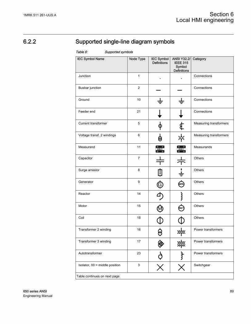
6.2.2 Supported single-line diagram symbolsTable 6: Supported symbols
IEC Symbol Name Node Type IEC SymbolDefinitions
ANSI Y32.2/IEEE 315Symbol
Definitions
Category
Junction 1 Connections
Busbar junction 2 Connections
Ground 10 Connections
Feeder end 21 Connections
Current transformer 5 Measuring transformers
Voltage transf. 2 windings 6 Measuring transformers
Measurand 11 Measurands
Capacitor 7 Others
Surge arrestor 8 Others
Generator 9 Others
Reactor 14 Others
Motor 15 Others
Coil 18 Others
Transformer 2 winding 16 Power transformers
Transformer 3 winding 17 Power transformers
Autotransformer 23 Power transformers
Isolator, 00 = middle position 3 Switchgear
Table continues on next page
1MRK 511 261-UUS A Section 6Local HMI engineering
650 series ANSI 89Engineering Manual

IEC Symbol Name Node Type IEC SymbolDefinitions
ANSI Y32.2/IEEE 315Symbol
Definitions
Category
Isolator, 01 = Open 3 Switchgear
Isolator, 10 = Closed 3 Switchgear
Isolator, 11 = Undefined 3 Switchgear
Breaker, 00 = Middle position 4 Switchgear
Breaker, 01 = Open 4 Switchgear
Breaker, 10 = Closed 4 Switchgear
Breaker, 11 = Undefined 4 Switchgear
Truck, 00 = Middle position 22 Switchgear
Truck, 01 = Open 22 Switchgear
Truck, 10 = Closed 22 Switchgear
Truck, 11 = Undefined 22 Switchgear
Isolator indication only, 00 =Middle position
25 Switchgear
Isolator indication only, 01 =Open
25 Switchgear
Isolator indication only, 10 =Closed
25 Switchgear
Isolator indication only, 11 =Undefined
25 Switchgear
Breaker indication only, 00 =Middle position
26 Switchgear
Breaker indication only, 01 =Open
26 Switchgear
Breaker indication only, 10 =Closed
26 Switchgear
Breaker indication only, 11 =Undefined
26 Switchgear
Table continues on next page
Section 6 1MRK 511 261-UUS ALocal HMI engineering
90 650 series ANSIEngineering Manual

IEC Symbol Name Node Type IEC SymbolDefinitions
ANSI Y32.2/IEEE 315Symbol
Definitions
Category
Isolator motor operated, 00 =Middle position
27 Switchgear
Isolator motor operated, 01 =Open
27 Switchgear
Isolator motor operated, 10 =Closed
27 Switchgear
Isolator motor operated, 11 =Undefined
27 Switchgear
Isolator2, 00 = Middle position 32 Switchgear
Isolator2, 01 = Open 32 Switchgear
Isolator2, 10 = Closed 32 Switchgear
Isolator2, 11 = Undefined 32 Switchgear
Isolator2 indication only, 00 =Middle position
33 Switchgear
Isolator2 indication only, 01 =Open
33 Switchgear
Isolator2 indication only, 10 =Closed
33 Switchgear
Isolator2 indication only, 11 =Undefined
33 Switchgear
Breaker2, 00 = Middle position 34 Switchgear
Breaker2, 01 = Open 34 Switchgear
Breaker2, 10 = Closed 34 Switchgear
Breaker2, 11 = Undefined 34 Switchgear
Breaker2 indication only, 00 =Middle position
35 Switchgear
Breaker2 indication only, 01 =Open
35 Switchgear
Breaker2 indication only, 10 =Closed
35 Switchgear
Table continues on next page
1MRK 511 261-UUS A Section 6Local HMI engineering
650 series ANSI 91Engineering Manual

IEC Symbol Name Node Type IEC SymbolDefinitions
ANSI Y32.2/IEEE 315Symbol
Definitions
Category
Breaker2 indication only, 11 =Undefined
35 Switchgear
Static text 0 Texts
Dynamic text 29 Texts
Select button, 00 = Middleposition
30 Texts
Select button, 01 = Open 30 Texts
Select button, 10 = Closed 30 Texts
Select button, 11 = Undefined 30 Texts
Indication button, 00 = Middleposition
31 Texts
Indication button, 01 = Open 31 Texts
Indication button, 10 = Closed 31 Texts
Indication button, 11 = Undefined 31 Texts
6.2.3 Bay configuration engineeringA page with a single line diagram and measurements contains active living objects.The object values are updated by the IED periodically (measurement) or in case of anevent. Once the symbols are placed on the HMI page they must be linked to thecorresponding function block in the application configuration, which protects orcontrols the object that the symbol on the HMI page represents.
Creating a complete HMI display pageProcedure:
1. Make a sketch how to present the single line diagram.2. Place the apparatus, transformer and other symbols that are needed for the single
line diagram into the raster boxes.3. Add connection points where needed.
Section 6 1MRK 511 261-UUS ALocal HMI engineering
92 650 series ANSIEngineering Manual
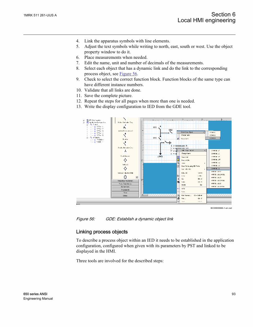
4. Link the apparatus symbols with line elements.5. Adjust the text symbols while writing to north, east, south or west. Use the object
property window to do it.6. Place measurements when needed.7. Edit the name, unit and number of decimals of the measurements.8. Select each object that has a dynamic link and do the link to the corresponding
process object, see Figure 56.9. Check to select the correct function block. Function blocks of the same type can
have different instance numbers.10. Validate that all links are done.11. Save the complete picture.12. Repeat the steps for all pages when more than one is needed.13. Write the display configuration to IED from the GDE tool.
IEC09000666-1-en.vsd
IEC09000666 V1 EN
Figure 56: GDE: Establish a dynamic object link
Linking process objectsTo describe a process object within an IED it needs to be established in the applicationconfiguration, configured when given with its parameters by PST and linked to bedisplayed in the HMI.
Three tools are involved for the described steps:
1MRK 511 261-UUS A Section 6Local HMI engineering
650 series ANSI 93Engineering Manual

• ACT to program the application function block for apparatus and/or measurements.• PST to adapt the settings and/or configuration parameter of the application
function block.• GDE to establish the link for updating the selected data attribute in the HMI of the
application function block.
The following application function blocks are used to deliver the needed information:
• Switch controller (of type CSWI) for an apparatus.• All configured function blocks with measurements (of type MMXU) for the
measurements.• VSGGIO for one bit indications for the dynamic text symbols.• SLGGGIO for 32 bit indications for the dynamic text symbols.
Procedure
1. Right-click the apparatus symbol and select Select Input Signal. A list ofengineered switch control application function blocks opens, see Figure 57.
2. Select the switch control application function block that corresponds to theselected apparatus.
3. Right-click the measurement symbol and select Select Input Signal. A list of theengineered measurement application function blocks opens.
4. Select the measurement application function block that corresponds to the selectedsymbol.
Section 6 1MRK 511 261-UUS ALocal HMI engineering
94 650 series ANSIEngineering Manual
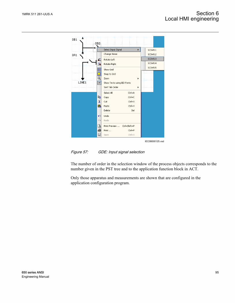
IEC08000125.vsdIEC08000125 V1 EN
Figure 57: GDE: Input signal selection
The number of order in the selection window of the process objects corresponds to thenumber given in the PST tree and to the application function block in ACT.
Only those apparatus and measurements are shown that are configured in theapplication configuration program.
1MRK 511 261-UUS A Section 6Local HMI engineering
650 series ANSI 95Engineering Manual

en05000611.vsd
IEC05000611 V1 EN
Figure 58: GDE: Object properties windows for text insertion
The single line diagram screen can display different values, with thehelp of the dynamic text fields. Please remember that these values aredisplayed by default in SI units (for example - active power is displayedin W). Modify the Scale Factor in the object properties (see Figure 59)to display values in more readable units (for example MW). Be sure towrite the proper unit under the Unit Text field.
As the function delivers angles in radians, a scale factor of 180/pi =57,3 shall be used to display the angle in degrees
IEC10000174.vsdIEC10000174 V1 EN
Figure 59: GDE: Object properties window for unit change
Section 6 1MRK 511 261-UUS ALocal HMI engineering
96 650 series ANSIEngineering Manual

6.3 Events and indications
To get IED events to the LHMI event list and indications for Ready, Pickup and Tripindication LEDs, disturbance report needs to be engineered.
Detailed information about disturbance report subfunctions is found inthe technical manual.
1MRK 511 261-UUS A Section 6Local HMI engineering
650 series ANSI 97Engineering Manual

98

Section 7 IEC 61850 communication engineering
7.1 IEC 61850 interface in the IED and tools
For more information on the implementation of IEC 61850 standards inIEDs, see the IEC 61850 communication protocol manual.
7.1.1 Function view for IEC 61850 in PCM600The IED function blocks have a design based on the demands and advantages of theIEC 61850 standard. This means that there is a strict relation between the functionblocks and the logical node types. This relation is automatically handled by thePCM600 tools.
The concept in IED is such that the 61850 data for each function instantiated in ACTwill be automatically created. This means that the user do not need to handle anyinstance information for the functions regarding IEC 61850.
7.1.2 IEC 61850 interface in IEDSee Figure 60 for a principle view of the IEC 61850 logical node concept in the IED.
1MRK 511 261-UUS A Section 7IEC 61850 communication engineering
650 series ANSI 99Engineering Manual

IEC08000364.vsd
LNGOOSE
Send
Com
mun
icat
ion
hand
ler
IEC
618
50 p
roto
col
Commands
Eventhandler
Eventqueue
Com
man
d / I
N /
OU
T in
terfa
ce A
F pa
rt
GOOSE Send
GOOSE Receive
FBswith
monitoring and
commands
FBswith
monitoring only
GO
OS
E in
terf.
FBAFL
LNpart
FBAFL
LNpart
FBAFL
LNpart
LNGOOSE
Send
FBsGOOSEReceive
FBsGOOSEReceive
IEC08000364 V1 EN
Figure 60: IEC 61850: Communication interface principle
IEC 61850 has as a concept for the identification of all signals for communication thatbelong to a function by a logical node as a placeholder. All signal information incommand and monitoring direction, which belongs to a function, is available withinthe logical node.
Whenever a function block is instantiated in ACT, PCM600 automatically generatesthe corresponding logical node data. In Figure 60 this is shown by two parts perfunction block. The upper part is the visible function block in ACT and the lower partis the logical node data for the function block.
7.1.2.1 GOOSE data exchange
The IEC 61850 protocol supports a method to directly exchange data between two ormore IEDs. This method is described in the IEC 61850–7–2 clause 15. The concept isbased on sending a multicast over the Ethernet. Whoever needs the information detects
Section 7 1MRK 511 261-UUS AIEC 61850 communication engineering
100 650 series ANSIEngineering Manual
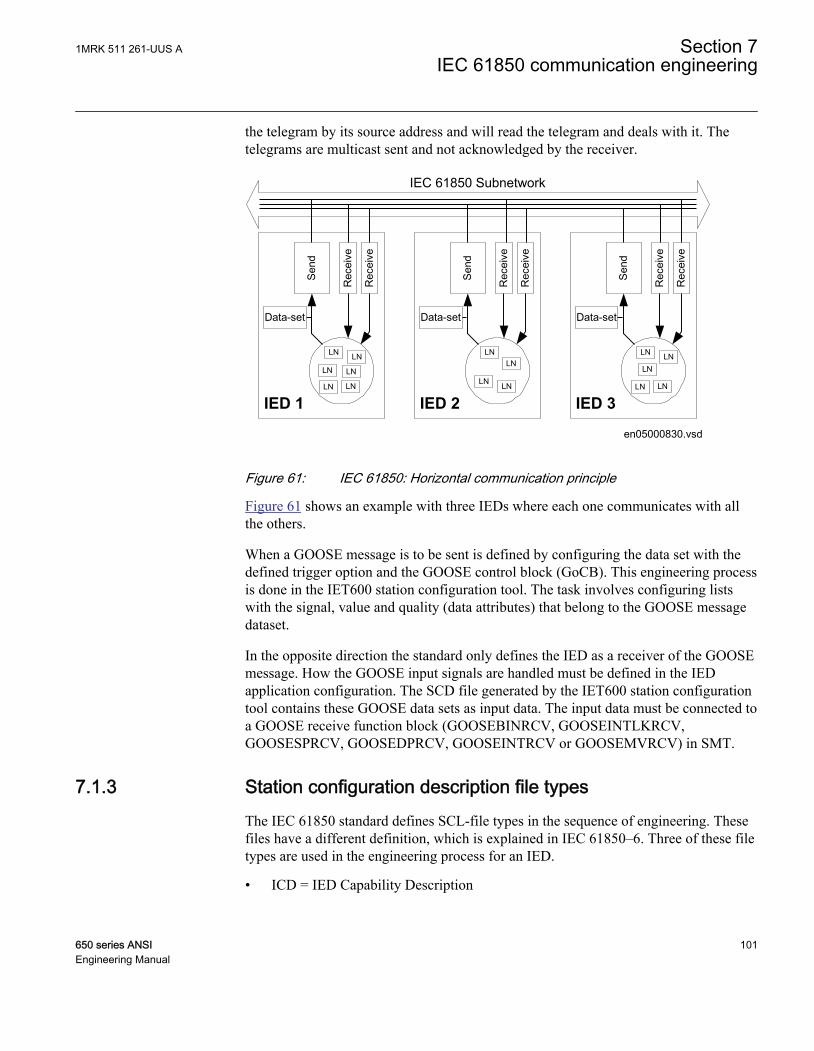
the telegram by its source address and will read the telegram and deals with it. Thetelegrams are multicast sent and not acknowledged by the receiver.
en05000830.vsd
IED 3
Sen
d
Data-set
Rec
eive
Rec
eive
LN
LN
LNLN
LN
IED 2
Sen
d
Data-set
Rec
eive
Rec
eive
LNLN
LN LN
IED 1
Sen
dData-set
Rec
eive
Rec
eive
LN
LNLN
LNLN
LN
IEC 61850 Subnetwork
IEC05000830 V1 EN
Figure 61: IEC 61850: Horizontal communication principle
Figure 61 shows an example with three IEDs where each one communicates with allthe others.
When a GOOSE message is to be sent is defined by configuring the data set with thedefined trigger option and the GOOSE control block (GoCB). This engineering processis done in the IET600 station configuration tool. The task involves configuring listswith the signal, value and quality (data attributes) that belong to the GOOSE messagedataset.
In the opposite direction the standard only defines the IED as a receiver of the GOOSEmessage. How the GOOSE input signals are handled must be defined in the IEDapplication configuration. The SCD file generated by the IET600 station configurationtool contains these GOOSE data sets as input data. The input data must be connected toa GOOSE receive function block (GOOSEBINRCV, GOOSEINTLKRCV,GOOSESPRCV, GOOSEDPRCV, GOOSEINTRCV or GOOSEMVRCV) in SMT.
7.1.3 Station configuration description file typesThe IEC 61850 standard defines SCL-file types in the sequence of engineering. Thesefiles have a different definition, which is explained in IEC 61850–6. Three of these filetypes are used in the engineering process for an IED.
• ICD = IED Capability Description
1MRK 511 261-UUS A Section 7IEC 61850 communication engineering
650 series ANSI 101Engineering Manual

The IED name in an exported .icd file is always named TEMPLATE.
• Capability description of the IED in logical nodes and their data. Noinformation about communication configuration, for example, is included.
• An IED is already extended by default data sets. They are predefined byABB. Changes or additional data sets, for example, have to be done with theIET600 station configuration tool.
• SCD = Station Configuration Description• Complete configuration description of all IEDs in a station and the full
engineering of process signals and communication structure is included. Thisincludes all needed data sets and all control blocks.
• CID = Configured IED Description• The CID file contains the information needed to configure just one specific
IED.
The uploading of IEC 61850 communication configuration is notsupported when reading a configuration from an online IED.
7.2 IEC 61850 engineering procedure
7.2.1 IEC 61850 protocol references and pre-conditionsTo engineer the IEC 61850 protocol interface for the IED, the following additionalmanuals or knowledge of their contents is required.
• Knowledge of the IEC 61850 engineering process as described in the IEC 61850standard.
• The Technical Manual describes function blocks defined as logical nodes.• The IEC 61850 Communication Protocol Manual.• The IEC 61850 conformance documents for the IED to be engineered.
7.2.2 Sequence for engineering of IEC 61850 protocolThe IEC 61850 standard defines the complete part needed for informationcommunication in a substation. This can be split into the following parts:
Section 7 1MRK 511 261-UUS AIEC 61850 communication engineering
102 650 series ANSIEngineering Manual

• Description of the substation part including the used logical nodes• Description of the IEDs with their logical nodes• Description of the communication network• Description of the engineering process
For more details please refer to the IEC 61850 standards. In the following description itis assumed that PCM600 together with IET600 is used as system configuration tool.
A short form of a typical sequence is shown in Figure 62 when a complete station isexported as a SCD file.
1. Export SCL files from PCM600. In the scenario in Figure 62 it is a SCD file.Other SCL file types are possible to export.
2. Configure horizontal and vertical communication in the IET600 stationconfiguration tool.
3. Import SCL files to PCM600 project. In the scenario in Figure 62 it is the updatedSCD file.
SCD file
do IED engineering export SCD file
PCM600 (1)
create project import SCD file configure data sets configure Report CBs configure GOOSE CBs export SCD file
IET600 (2)
import SCD file link GOOSE input data Write to IED
PCM600 (3)
SCD file
IED 1 IED nIED 2 IED n-1
IEC11000264.vsd
IEC11000264 V1 EN
Figure 62: IEC 61850: Signal engineering procedure flow
1MRK 511 261-UUS A Section 7IEC 61850 communication engineering
650 series ANSI 103Engineering Manual

7.3 Exporting SCL files from PCM600
A pre-condition is that all IEDs in the project must be engineered in PCM600. Thehardware interface, for example the communication port, has to be selected andconfigured. The used interface addresses have to be set according to protocol andproject definitions. The station communication port has to be activated in the IED, thatis to set the IEC61850-8-1Operation setting to Enabled.
7.3.1 Exporting SCD filesProcedure to export the SCD file from PCM600:
1. Select the station in the plant structure, see Figure 63.
IEC08000415.vsd
Station
IEC08000415 V1 EN
Figure 63: IEC 61850: Export SCD step 1
2. Right-click the station and select Export ....3. Select a location from the open standard Windows menu to store the file and name
it.4. The SCL Export Options window opens, see Figure 64.
Section 7 1MRK 511 261-UUS AIEC 61850 communication engineering
104 650 series ANSIEngineering Manual

IEC09000627-1-en.vsdIEC09000627 V1 EN
Figure 64: IEC 61850: SCL Export Options
5. Select Export Private Sections and click Export to export the private sections tothe SCD file. A progress window shows the ongoing export of the station.
7.3.2 Exporting ICD or CID filesProcedure to select the export type, when the IED is selected in the plant structure:
1. Right-click the IED in the plant structure and select Export to open the Exportwindow.
2. Select the type of file to export from the Save as type drop down list.• Configured IED Description (*.cid) for the IEC 61850 structure as needed
for the IED at runtime.• IED Capability Description (*.icd) for the IEC 61850 structure, see Figure
65.
IEC08000416.vsdIEC08000416 V1 EN
Figure 65: IEC 61850: Export IED file type selection
3. The SCL Export Options window opens.4. Select Export Private Sections, Export As SCL Template or Include Goose Sending
IEDs and click Export, see Figure 66. Note that the options in SCL Export Optionswindow according to Figure 66 is only available when an ICD file is exported.
1MRK 511 261-UUS A Section 7IEC 61850 communication engineering
650 series ANSI 105Engineering Manual

IEC08000418.vsdIEC08000418 V1 EN
Figure 66: IEC 61850: Export IED file Options
7.4 Engineering of vertical and horizontal communicationin IET600
For IEC 61850 engineering a separate system configuration tool is needed to be usedwith PCM600. In PCM600 Ver. 2.3 or earlier the recommended tool is CCT600. InPCM600 Ver. 2.4 or later the recommended tool is IET600, which is also included inthe PCM600 Engineering Pro installation package.
Procedure for signal engineering for the station by using IET600:
1. Create a project in IET600.2. Import the SCD file exported from PCM600.
All data sets, report control blocks and GOOSE control blocksmust be located at LD0/LLN0. Due to IED capability, there arelimitations regarding the maximum number of data sets, number ofentries in a data set and the number of report control blocks thatcan be used.
3. Add and/or reconfigure default data sets. The 650 series pre-configured IEDincludes a number of predefined data sets, but it is possible to add additional datasets and/or reconfigure default data sets according to the requirements.
Note that reporting data sets shall only contain data intended to beused by clients, for example for event handling.
4. Configure report control blocks for each data set used for vertical communication.The 650 series pre-configured IED includes a number of predefined report control
Section 7 1MRK 511 261-UUS AIEC 61850 communication engineering
106 650 series ANSIEngineering Manual

blocks, but it is possible to add additional control blocks and/or reconfigure defaultcontrol blocks according to the requirements.
Up to 8 report clients can be configured.
5. Connect the report control blocks to vertical IED clients. The report control blocksare connected to the vertical clients in the SCD file for a 650 series pre-configuredIED. Check each IED client and configure them to the subnetwork beforeconnecting report control blocks to the clients.
6. Create a GOOSE message data set for the sending IED. Define the attributecontent of the data set according to the requirements.
The data set for GOOSE may contain signals on data attribute levelor on FCDA level. The latter is also called structured GOOSE.
Ensure that the same GoID is set for sending and receivingGOOSE messages.
Note that one data must only be included in one GOOSE data set.
7. Create the GOOSE control block and connect it to the GOOSE message data set.Be sure to check the parameters for the GOOSE control block and update as required.
8. Connect the GOOSE control block to the client IEDs, subscribing for GOOSE.9. Export the updated SCD file.
Please see the IET600 user manual for additional information aboutvertical and horizontal station communication engineering.
7.5 Importing SCL files to PCM600
The IED engineering tool must be able to receive a SCD file or an ICD file as import toreceive the engineered communication extensions, for example for the different IEDs.
1MRK 511 261-UUS A Section 7IEC 61850 communication engineering
650 series ANSI 107Engineering Manual

7.5.1 Importing SCD filesProcedure to import a SCD file to PCM600:
1. Select the station in the plant structure.2. Right-click the station and select Import ...3. Select the file to be imported from the open standard Windows menu and start the
reading.4. A SCL Import Options window opens, which queries how the file should be
handled during import, see Figure 67.
IEC09000631-1-en.vsdIEC09000631 V1 EN
Figure 67: IEC 61850: Import SCD file
4.1. Click Ignore Substation Section to not import the "SSD-file" part of the SCD-file.
4.2. Click Don't import IEDs of unknown type to protect the existing IEDs in casethe SCD file does not match the original configuration in PCM600.
4.3. Click Replace unknown ... can be used when it is known, that the fileincludes additional IEDs that are needed. The IED of type “Generic IEC61850 IED” is used to integrate these kinds of IEDs in the plant structure etc.
4.4. Click Ignore PCM Object Type to update the IED object(s) in PCM600 fromthe IED type(s) in the SCD file, disregarding if the IED type(s) in the SCDfile matches the IED object(s) in PM600 or not.
4.5. Start Import when the file definition has been completed. A progresswindow presents the import procedure.
5. Make connections from sending IEDs to receiving function blocks in SMT.5.1. Make connections between the signals that the server is sending and all the
GOOSE receive interface function blocks included in the applicationconfiguration on the client’s side.
Section 7 1MRK 511 261-UUS AIEC 61850 communication engineering
108 650 series ANSIEngineering Manual

If a client is defined for GOOSE receive then at least one cross inSMT is required to be able to write the configuration to the IED.
Be sure to set the setting Operation to Enabled in PST for allincluded GOOSE receiving function blocks in the applicationconfiguration to enable GOOSE communication.
6. Write the configuration to the IED, see Figure 68.
Note that the engineered data is written to the IED when executinga common Write to IED operation.
1MRK 511 261-UUS A Section 7IEC 61850 communication engineering
650 series ANSI 109Engineering Manual
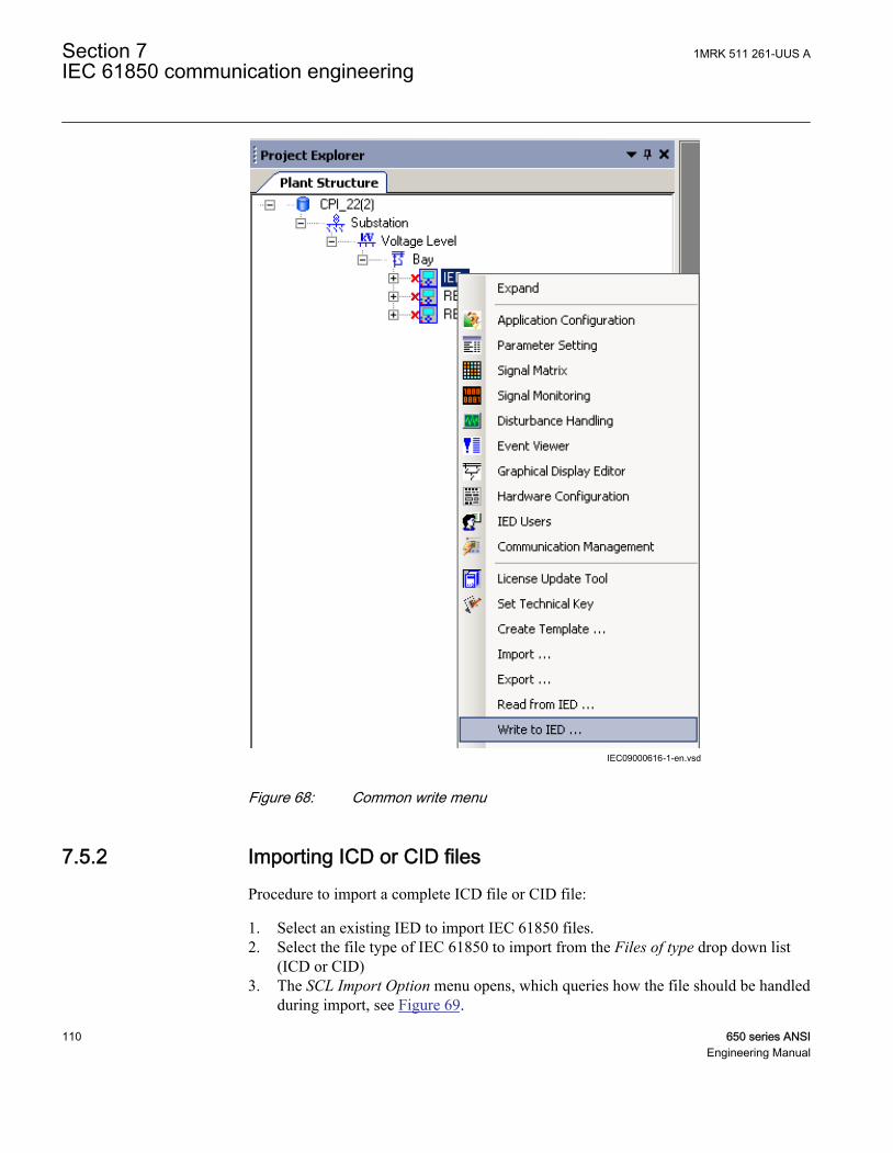
IEC09000616-1-en.vsdIEC09000616 V1 EN
Figure 68: Common write menu
7.5.2 Importing ICD or CID filesProcedure to import a complete ICD file or CID file:
1. Select an existing IED to import IEC 61850 files.2. Select the file type of IEC 61850 to import from the Files of type drop down list
(ICD or CID)3. The SCL Import Option menu opens, which queries how the file should be handled
during import, see Figure 69.
Section 7 1MRK 511 261-UUS AIEC 61850 communication engineering
110 650 series ANSIEngineering Manual

3.1. Ignore Substation Section will not import the "SSD-file" part of the SCD-file.3.2. Don't import ... protects the existing IEDs in case the SCD file does not
match the original configuration in PCM600.3.3. Replace unknown ... can be used when it is known that the file includes
additional IEDs which are needed. The IED of type Generic IEC 61850 IEDis used to integrate these kinds of IEDs in for example the plant structure.
3.4. Click Ignore PCM Object Type to update the IED object(s) in PCM600 fromthe IED type(s) in the SCD file, disregarding if the IED type(s) in the SCDfile matches the IED object(s) in PM600 or not.
3.5. Start Import when the definition has been completed. A progress windowpresents the import procedure.
4.
IEC09000631-1-en.vsdIEC09000631 V1 EN
Figure 69: IEC 61850: SCL Import option
7.6 Writing communication configuration to IED
IEC communication depends on proper communication configuration in all IEDs thatcommunicate via IEC 61850. It is not possible to read the communicationconfiguration from the IED to PCM600.
However it is possible to make a configuration change in one IED, without affectingthe communication engineering. For example, when the Application Configuration toolconfiguration is changed, but no changes are done for the instantiation or deletion offunctions that represent a logical node.
When a changed configuration is written to the IED, the user is asked to update thecommunication configuration.
1MRK 511 261-UUS A Section 7IEC 61850 communication engineering
650 series ANSI 111Engineering Manual

1. Select Yes in the Update Communication window to update the communicationconfiguration part in the IED.
2. Click No in the Update Communication window to keep the communicationconfiguration part in the IED. Other parts of the configuration will be updated.
If no changes have been done in the communication configuration part,click No in the Update Communication window.
IEC09000729-1-en.vsdIEC09000729 V1 EN
Figure 70: Update the communication configuration in the IED with theconfiguration made in PCM600
Section 7 1MRK 511 261-UUS AIEC 61850 communication engineering
112 650 series ANSIEngineering Manual
Section 8 IEC 60870-5-103 communicationengineering
8.1 Engineering in PCM600
The Application Configuration tool (ACT) and the Parameter Setting tool (PST) inPCM600 are used to configure the communication for IEC 60870-5-103 protocol.
1. Add the desired IEC 60870-5-103 function blocks to the applicationconfiguration in the Application Configuration tool.
2. Connect the outputs of desired protection and monitoring function in theapplication configuration to the inputs of the corresponding IEC 60870-5-103function block.
3. Set the function type and desired information number, where an informationnumber must be supplied, for each IEC 60870-5-103 function block instance inthe Parameter Setting tool.
4. Set the general communication settings for IEC 60870-5-103, available infunction RS485103 or OPTICAL103 depending on choice of serial interface, andtime synchronization parameters in the Parameter Setting tool.
See the Communication protocol manual for IEC 60870-5-103 for more informationabout the IEC 60870-5-103 implementation in 650 series.
The COM05 module is equipped with an optical serial and RS485serial communication interface. IEC60870-5-103 can be communicatedfrom either of these serial interfaces. The user must select in PST whichinterface to use.
8.1.1.1 Selecting to communicate IEC60870-5-103 data via RS485 serialinterface on COM05 module
1MRK 511 261-UUS A Section 8IEC 60870-5-103 communication engineering
650 series ANSI 113Engineering Manual

1. In PST, navigate to the RS485PROT function block located in MainMenu/IEDConfiguration/Monitoring/RS485PROT:1.
2. To enable the IEC60870-5-103 protocol on the RS485 port, select IEC103 forsetting Operation.
3. Navigate to the RS485103 function block, found in MainMenu/IEDConfiguration/Communication/I103/RS485103:1, to set IEC60870-5-103communications port properties, such as baud-rate or master time domain.
8.1.1.2 Selecting to communicate IEC60870-5-103 data via optical serialinterface on COM05 module
1. In PST, navigate to the OPTICALPROT function block located in MainMenu/IEDConfiguration/Monitoring/OPTICALPROT:1.
2. To enable the IEC60870-5-103 protocol on the RS485 port, select IEC103 forsetting Operation.
3. Navigate to the OPTICAL103 function block, found in MainMenu/IEDConfiguration/Communication/I103/OPTICAL103:1, to setIEC60870-5-103 communications port properties, such as baud-rate or mastertime domain.
Section 8 1MRK 511 261-UUS AIEC 60870-5-103 communication engineering
114 650 series ANSIEngineering Manual

Section 9 DNP3 communication engineering
9.1 Signal configuration user information
Basic knowledge about DNP3 and the used definitions are required touse CMT. See the DNP3 communication protocol manual forinformation on the DNP3 implementation in the IED.
CMT allows to configure the signals that are used to communicate with clients ormaster units for DNP3 protocols.
On the left window CMT organizes all available signals from the applicationconfiguration in containers that are preselected as signal types.
On the right window CMT provides containers that are selected by tabs. Each containerrepresents one communication channel. The number of possible communicationchannels is IED type dependent. The IED uses TCP/IP as communication channel.DNP3 can be tunneled over TCP/IP. Serial communication RS-485 is supported. .
Use direction icons that are located between the windows to move all signals or a set ofindividual signals between the windows.
DNP3 signal types, index and default setting for classes are predefined in CMT. Adaptthe signal configuration to project definitions. The signal type can not be modified dueto the fact that the internal signal set up is fixed.
When the default configuration values are sufficient, the task is finished when allsignal are moved according to the project requirements.
With the Save option, the signals are stored for the communication part of the IEDaccording to the default selections.
Only for analog measurements additional configuration parameters are shown to dosignal scaling to DNP3 protocol presentation. This can be done when theConfiguration Table View is selected.
Finally, the signal configuration to the different DNP3 channels can be listed in areport on demand and per signal type.
1MRK 511 261-UUS A Section 9DNP3 communication engineering
650 series ANSI 115Engineering Manual
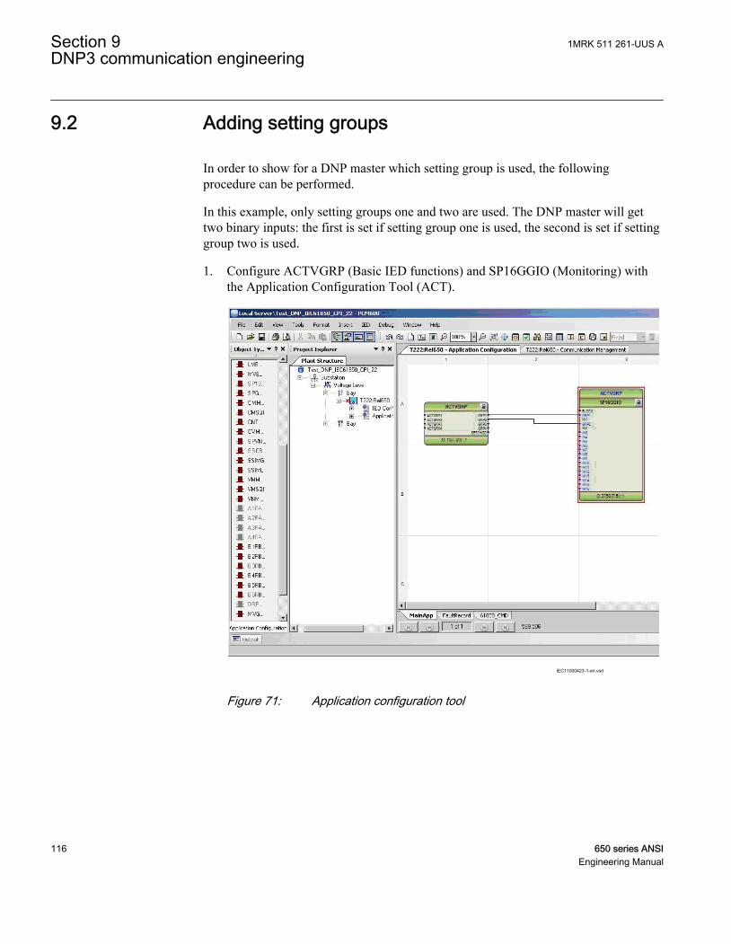
9.2 Adding setting groups
In order to show for a DNP master which setting group is used, the followingprocedure can be performed.
In this example, only setting groups one and two are used. The DNP master will gettwo binary inputs: the first is set if setting group one is used, the second is set if settinggroup two is used.
1. Configure ACTVGRP (Basic IED functions) and SP16GGIO (Monitoring) withthe Application Configuration Tool (ACT).
IEC11000423-1-en.vsd
IEC11000423 V1 EN
Figure 71: Application configuration tool
Section 9 1MRK 511 261-UUS ADNP3 communication engineering
116 650 series ANSIEngineering Manual

To make it easier to recognize the signals for the active settinggroup, the user-defined names are used.
2. Open the Communication Management Tool (CMT). Set the Signal Type toBinary Input Object and choose the connection of the master for which the valuesshould be presented.
IEC11000424-1-en.vsd
IEC11000424 V1 EN
Figure 72: Communication Management tool
3. Select the signals and move them into the DNP signal list of the master. DNPpoint zero and one of the Binary Input Objects are used for indicating the activesetting group in this case.
1MRK 511 261-UUS A Section 9DNP3 communication engineering
650 series ANSI 117Engineering Manual
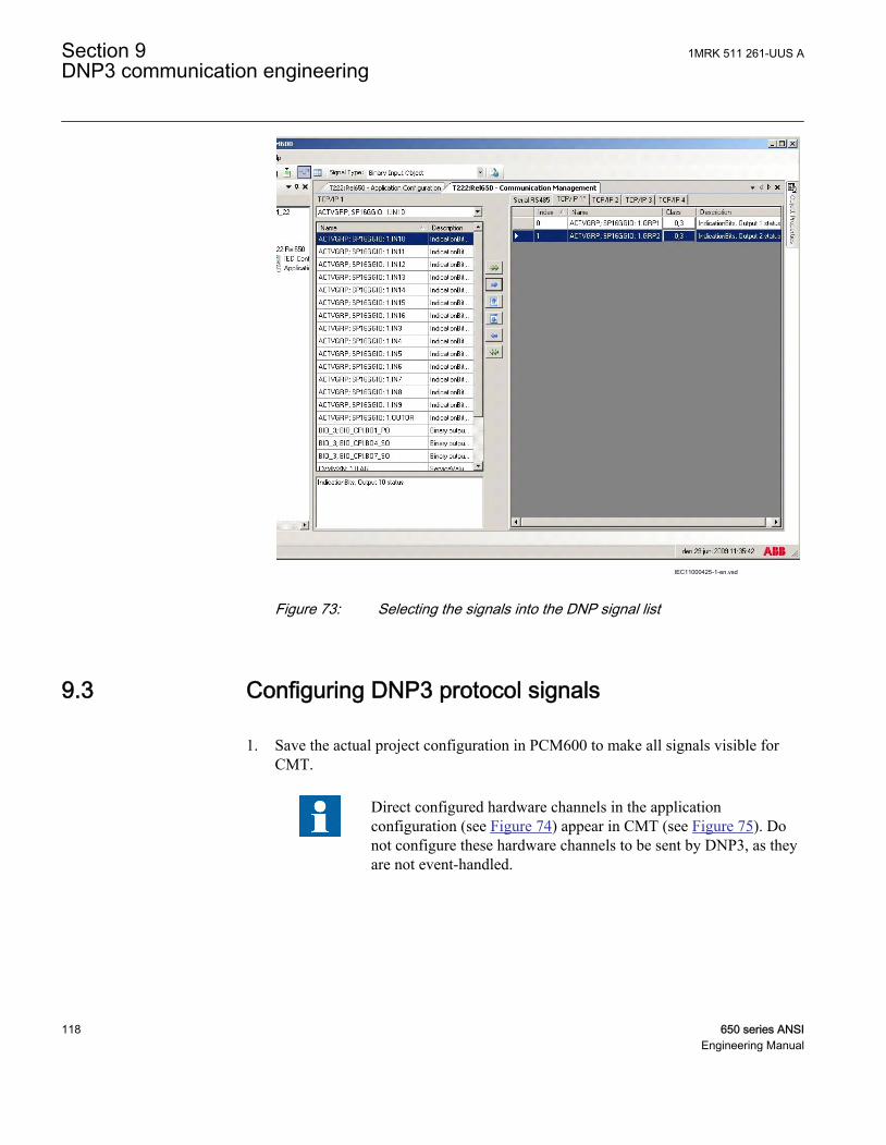
IEC11000425-1-en.vsd
IEC11000425 V1 EN
Figure 73: Selecting the signals into the DNP signal list
9.3 Configuring DNP3 protocol signals
1. Save the actual project configuration in PCM600 to make all signals visible forCMT.
Direct configured hardware channels in the applicationconfiguration (see Figure 74) appear in CMT (see Figure 75). Donot configure these hardware channels to be sent by DNP3, as theyare not event-handled.
Section 9 1MRK 511 261-UUS ADNP3 communication engineering
118 650 series ANSIEngineering Manual

IEC10000172.vsd
IEC10000172 V1 EN
Figure 74: Configuring hardware channels directly to the function blocks
IEC10000173.vsd
IEC10000173 V1 EN
Figure 75: CMT: Hardware channels appearing in the CommunicationManagement Tool
2. Right-click the IED in the plant structure and select Communication Managementto start the Communication management tool.
3. Select the DNP3 protocol from the new window and click OK. Figure 76 presentsthe design of the two container windows, which open after the selection of DNP3.• The right window shows tabs for possible communication channels.• The left window has a drop down menu for signal selection and buttons for
signal movement, see Figure 76.
1MRK 511 261-UUS A Section 9DNP3 communication engineering
650 series ANSI 119Engineering Manual

IEC08000337.vsdIEC08000337 V1 EN
Figure 76: CMT: Container window design when selecting DNP3 protocol
Procedure to move signals:
1. Select one or several signals.• Click in the list of signals to select one signal.• Press Shift or Ctrl and several signals to select a set of signals.• Right-click in the list of signals, select Select All from the context menu or
press Ctrl+A to select all signals.2. Press the blue arrow button to insert the selected signals into the configuration.3. Press the green double arrow button to insert all signals into the configuration, see
Figure 77.
IEC08000361.vsdIEC08000361 V1 EN
Figure 77: CMT: Move buttons
4. Click the drop down list Signal Type: to select the other signal types for this channel.5. Repeat to move signals for all signal types and save the selection.
Content changes in the DNP3 container are marked with a star at theend of the name, see Figure 78. The star indicates that changes in thecontainer have to be saved before leaving CMT.
Section 9 1MRK 511 261-UUS ADNP3 communication engineering
120 650 series ANSIEngineering Manual

IEC08000339.vsdIEC08000339 V1 EN
Figure 78: CMT: Marker to indicate changes in the container
9.4 Setting DNP3 signal parameters
Two parameters per signal can be set for all signal types:
• The index of the signal• The class configuration
Procedure to set the index of the signal:
1. Click the two inner arrows to sort signals to another index sequence, or select SetIndex ... from the context menu to move one or a set of signals to another array,see Figure 79.
IEC08000336.vsdIEC08000336 V1 EN
Figure 79: CMT: Context menu in DNP3 window
2. The selection window shows the number of signals selected, see Figure 80.
1MRK 511 261-UUS A Section 9DNP3 communication engineering
650 series ANSI 121Engineering Manual

IEC08000363.vsdIEC08000363 V1 EN
Figure 80: CMT: Set Index menu
3. Define the Starting index for this group and click OK.
Procedure to set class configuration:
1. Click in the class field of the signal to change the class configuration.2. The Select Class window opens.3. Make the selection according to the definitions in the project and click OK to close
the window and get the new configuration, see Figure 81.
IEC08000338.vsdIEC08000338 V1 EN
Figure 81: CMT: Select Class window
9.4.1 Configuring DNP3 classIn DNP3 the user classifies the signals and defines those signals that are not member ofany class. CMT has a default predefined organization of classes per signal type. In themaster station the classes can be polled in sequences according to the demands in theproject. Unsolicited reporting is possible as well.
Modify the organization of the classes for each signal individually.
Section 9 1MRK 511 261-UUS ADNP3 communication engineering
122 650 series ANSIEngineering Manual

Procedure
1. Click in the Class field of the signal. A new window Select Class opens where theuser classifies the signal.
2. Select the signal classes and choose between None and 0 to 3 according to theproject demands.
3. Click OK to set the signal classification.4. Write to IED.
9.4.2 Selecting to communicate DNP3 data via RS485 serialinterface on COM05 module
1. In PST, navigate to the RS485PROT function block located in MainMenu/IEDConfiguration/Monitoring/RS485PROT:1.
2. To enable the DNP3 protocol on the RS485 port, select DNP for settingOperation.
3. Navigate to the MSTSERIAL function block, located in MainMenu/IEDConfiguration/Communication/DNP3.0/MSTSERIAL:1 and setChToAssociate to RS485.
9.4.2.1 RS485 specific parameters
There are a few parameters that are specific to RS485 and are separated from theprotocols. This makes it possible to run RS485 hardware without defining anyprotocols. This enables the IED to operate correctly in a ring topology even if noprotocols are configured to run.
9.4.3 Selecting to communicate DNP3 data via optical serialinterface on COM05 module
1. In PST, navigate to the OPTICALPROT function block located in MainMenu/IEDConfiguration/Monitoring/OPTICALPROT:1.
2. To enable the DNP3 protocol on optical serial port, select DNP for settingOperation.
3. Navigate to the MSTSERIAL function block, located in MainMenu/IEDConfiguration/Communication/DNP3.0/MSTSERIAL:1, and setChToAssociate to Optical.
1MRK 511 261-UUS A Section 9DNP3 communication engineering
650 series ANSI 123Engineering Manual

124

Section 10 Glossary
AC Alternating current
ACT Application configuration tool within PCM600
A/D converter Analog-to-digital converter
ADBS Amplitude deadband supervision
AI Analog input
ANSI American National Standards Institute
AR Autoreclosing
ASCT Auxiliary summation current transformer
ASD Adaptive signal detection
AWG American Wire Gauge standard
BI Binary input
BOS Binary outputs status
BR External bistable relay
BS British Standards
CAN Controller Area Network. ISO standard (ISO 11898) for serialcommunication
CB Circuit breaker
CCITT Consultative Committee for International Telegraph andTelephony. A United Nations-sponsored standards body withinthe International Telecommunications Union.
CCVT Capacitive Coupled Voltage Transformer
Class C Protection Current Transformer class as per IEEE/ ANSI
CMPPS Combined megapulses per second
CMT Communication Management tool in PCM600
CO cycle Close-open cycle
Codirectional Way of transmitting G.703 over a balanced line. Involves twotwisted pairs making it possible to transmit information in bothdirections
1MRK 511 261-UUS A Section 10Glossary
650 series ANSI 125Engineering Manual

COMTRADE Standard Common Format for Transient Data Exchange formatfor Disturbance recorder according to IEEE/ANSI C37.111,1999 / IEC60255-24
Contra-directional Way of transmitting G.703 over a balanced line. Involves fourtwisted pairs, two of which are used for transmitting data inboth directions and two for transmitting clock signals
CPU Central processor unit
CR Carrier receive
CRC Cyclic redundancy check
CROB Control relay output block
CS Carrier send
CT Current transformer
CVT or CCVT Capacitive voltage transformer
DAR Delayed autoreclosing
DARPA Defense Advanced Research Projects Agency (The USdeveloper of the TCP/IP protocol etc.)
DBDL Dead bus dead line
DBLL Dead bus live line
DC Direct current
DFC Data flow control
DFT Discrete Fourier transform
DHCP Dynamic Host Configuration Protocol
DIP-switch Small switch mounted on a printed circuit board
DI Digital input
DLLB Dead line live bus
DNP Distributed Network Protocol as per IEEE/ANSI Std. 1379-2000
DR Disturbance recorder
DRAM Dynamic random access memory
DRH Disturbance report handler
DSP Digital signal processor
DTT Direct transfer trip scheme
EHV network Extra high voltage network
EIA Electronic Industries Association
Section 10 1MRK 511 261-UUS AGlossary
126 650 series ANSIEngineering Manual

EMC Electromagnetic compatibility
EMF (Electric Motive Force)
EMI Electromagnetic interference
EnFP End fault protection
EPA Enhanced performance architecture
ESD Electrostatic discharge
FCB Flow control bit; Frame count bit
FOX 20 Modular 20 channel telecommunication system for speech, dataand protection signals
FOX 512/515 Access multiplexer
FOX 6Plus Compact time-division multiplexer for the transmission of up toseven duplex channels of digital data over optical fibers
G.703 Electrical and functional description for digital lines used bylocal telephone companies. Can be transported over balancedand unbalanced lines
GCM Communication interface module with carrier of GPS receivermodule
GDE Graphical display editor within PCM600
GI General interrogation command
GIS Gas-insulated switchgear
GOOSE Generic object-oriented substation event
GPS Global positioning system
HDLC protocol High-level data link control, protocol based on the HDLCstandard
HFBR connectortype
Plastic fiber connector
HMI Human-machine interface
HSAR High speed autoreclosing
HV High-voltage
HVDC High-voltage direct current
IDBS Integrating deadband supervision
IEC International Electrical Committee
IEC 60044-6 IEC Standard, Instrument transformers – Part 6: Requirementsfor protective current transformers for transient performance
1MRK 511 261-UUS A Section 10Glossary
650 series ANSI 127Engineering Manual

IEC 61850 Substation automation communication standard
IEC 61850–8–1 Communication protocol standard
IEEE Institute of Electrical and Electronics Engineers
IEEE 802.12 A network technology standard that provides 100 Mbits/s ontwisted-pair or optical fiber cable
IEEE P1386.1 PCI Mezzanine Card (PMC) standard for local bus modules.References the CMC (IEEE P1386, also known as CommonMezzanine Card) standard for the mechanics and the PCIspecifications from the PCI SIG (Special Interest Group) for theelectrical EMF (Electromotive force).
IEEE 1686 Standard for Substation Intelligent Electronic Devices (IEDs)Cyber Security Capabilities
IED Intelligent electronic device
I-GIS Intelligent gas-insulated switchgear
Instance When several occurrences of the same function are available inthe IED, they are referred to as instances of that function. Oneinstance of a function is identical to another of the same kindbut has a different number in the IED user interfaces. The word"instance" is sometimes defined as an item of information that isrepresentative of a type. In the same way an instance of afunction in the IED is representative of a type of function.
IP 1. Internet protocol. The network layer for the TCP/IP protocolsuite widely used on Ethernet networks. IP is a connectionless,best-effort packet-switching protocol. It provides packetrouting, fragmentation and reassembly through the data link layer.2. Ingression protection, according to IEC standard
IP 20 Ingression protection, according to IEC standard, levelIP20- Protected against solidforeign objects of12.5mm diameterandgreater.
IP 40 Ingression protection, according to IEC standard, level IP40-Protected against solid foreign objects of 1mm diameter andgreater.
IP 54 Ingression protection, according to IEC standard, levelIP54-Dust-protected,protected againstsplashing water.
IRF Internal failure signal
IRIG-B: InterRange Instrumentation Group Time code format B,standard 200
ITU International Telecommunications Union
Section 10 1MRK 511 261-UUS AGlossary
128 650 series ANSIEngineering Manual

LAN Local area network
LIB 520 High-voltage software module
LCD Liquid crystal display
LDD Local detection device
LED Light-emitting diode
MCB Miniature circuit breaker
MCM Mezzanine carrier module
MVB Multifunction vehicle bus. Standardized serial bus originallydeveloped for use in trains.
NCC National Control Centre
OCO cycle Open-close-open cycle
OCP Overcurrent protection
OLTC On-load tap changer
OV Over-voltage
Overreach A term used to describe how the relay behaves during a faultcondition. For example, a distance relay is overreaching whenthe impedance presented to it is smaller than the apparentimpedance to the fault applied to the balance point, that is, theset reach. The relay “sees” the fault but perhaps it should nothave seen it.
PCI Peripheral component interconnect, a local data bus
PCM Pulse code modulation
PCM600 Protection and control IED manager
PC-MIP Mezzanine card standard
PMC PCI Mezzanine card
POR Permissive overreach
POTT Permissive overreach transfer trip
Process bus Bus or LAN used at the process level, that is, in near proximityto the measured and/or controlled components
PSM Power supply module
PST Parameter setting tool within PCM600
PT ratio Potential transformer or voltage transformer ratio
PUTT Permissive underreach transfer trip
RASC Synchrocheck relay, COMBIFLEX
1MRK 511 261-UUS A Section 10Glossary
650 series ANSI 129Engineering Manual

RCA Relay characteristic angle
RFPP Resistance for phase-to-phase faults
Resistance for phase-to-ground faults
RISC Reduced instruction set computer
RMS value Root mean square value
RS422 A balanced serial interface for the transmission of digital data inpoint-to-point connections
RS485 Serial link according to EIA standard RS485
RTC Real-time clock
RTU Remote terminal unit
SA Substation Automation
SBO Select-before-operate
SC Switch or push button to close
SCS Station control system
SCADA Supervision, control and data acquisition
SCT System configuration tool according to standard IEC 61850
SDU Service data unit
SMA connector Subminiature version A, A threaded connector with constantimpedance.
SMT Signal matrix tool within PCM600
SMS Station monitoring system
SNTP Simple network time protocol – is used to synchronize computerclocks on local area networks. This reduces the requirement tohave accurate hardware clocks in every embedded system in anetwork. Each embedded node can instead synchronize with aremote clock, providing the required accuracy.
SRY Switch for CB ready condition
ST Switch or push button to trip
Starpoint Neutral/Wye point of transformer or generator
SVC Static VAr compensation
TC Trip coil
TCS Trip circuit supervision
TCP Transmission control protocol. The most common transportlayer protocol used on Ethernet and the Internet.
Section 10 1MRK 511 261-UUS AGlossary
130 650 series ANSIEngineering Manual

TCP/IP Transmission control protocol over Internet Protocol. The defacto standard Ethernet protocols incorporated into 4.2BSDUnix. TCP/IP was developed by DARPA for Internet workingand encompasses both network layer and transport layerprotocols. While TCP and IP specify two protocols at specificprotocol layers, TCP/IP is often used to refer to the entire USDepartment of Defense protocol suite based upon these,including Telnet, FTP, UDP and RDP.
TNC connector Threaded Neill-Concelman, a threaded constant impedanceversion of a BNC connector
TPZ, TPY, TPX,TPS
Current transformer class according to IEC
UMT User management tool
Underreach A term used to describe how the relay behaves during a faultcondition. For example, a distance relay is underreaching whenthe impedance presented to it is greater than the apparentimpedance to the fault applied to the balance point, that is, theset reach. The relay does not “see” the fault but perhaps itshould have seen it. See also Overreach.
UTC Coordinated Universal Time. A coordinated time scale,maintained by the Bureau International des Poids et Mesures(BIPM), which forms the basis of a coordinated disseminationof standard frequencies and time signals. UTC is derived fromInternational Atomic Time (TAI) by the addition of a wholenumber of "leap seconds" to synchronize it with Universal Time1 (UT1), thus allowing for the eccentricity of the Earth's orbit,the rotational axis tilt (23.5 degrees), but still showing theEarth's irregular rotation, on which UT1 is based. TheCoordinated Universal Time is expressed using a 24-hour clock,and uses the Gregorian calendar. It is used for aeroplane andship navigation, where it is also sometimes known by themilitary name, "Zulu time." "Zulu" in the phonetic alphabetstands for "Z", which stands for longitude zero.
UV Undervoltage
WEI Weak end infeed logic
VT Voltage transformer
X.21 A digital signalling interface primarily used for telecomequipment
3IO Three times zero-sequence current. Often referred to as theresidual or the -fault current
1MRK 511 261-UUS A Section 10Glossary
650 series ANSI 131Engineering Manual

3VO Three times the zero sequence voltage. Often referred to as theresidual voltage or the neutral point voltage
Section 10 1MRK 511 261-UUS AGlossary
132 650 series ANSIEngineering Manual

133

Contact us
ABB Inc.1021 Main Campus DriveRaleigh, NC 27606, USAPhone Toll Free: 1-800-HELP-365,menu option #8
ABB Inc.3450 Harvester RoadBurlington, ON L7N 3W5, CanadaPhone Toll Free: 1-800-HELP-365,menu option #8
ABB Mexico S.A. de C.V.Paseo de las Americas No. 31 LomasVerdes 3a secc.53125, Naucalpan, Estado De Mexico,MEXICOPhone (+1) 440-585-7804, menuoption #8
1MR
K 5
11 2
61-U
US
A©
Cop
yrig
ht 2
012
AB
B. A
ll rig
hts
rese
rved
.