652-03 - cla-val
TRANSCRIPT
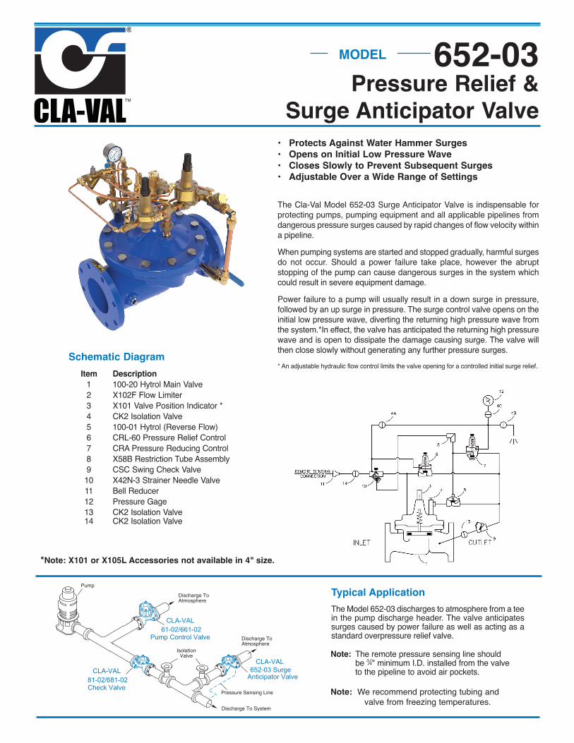
Pressure Relief &Surge Anticipator Valve
MODEL 652-03
• Protects Against Water Hammer Surges• Opens on Initial Low Pressure Wave• Closes Slowly to Prevent Subsequent Surges• Adjustable Over a Wide Range of Settings
The Cla-Val Model 652-03 Surge Anticipator Valve is indispensable forprotecting pumps, pumping equipment and all applicable pipelines fromdangerous pressure surges caused by rapid changes of flow velocity withina pipeline.When pumping systems are started and stopped gradually, harmful surgesdo not occur. Should a power failure take place, however the abruptstopping of the pump can cause dangerous surges in the system whichcould result in severe equipment damage.Power failure to a pump will usually result in a down surge in pressure,followed by an up surge in pressure. The surge control valve opens on theinitial low pressure wave, diverting the returning high pressure wave fromthe system.*In effect, the valve has anticipated the returning high pressurewave and is open to dissipate the damage causing surge. The valve willthen close slowly without generating any further pressure surges.* An adjustable hydraulic flow control limits the valve opening for a controlled initial surge relief.
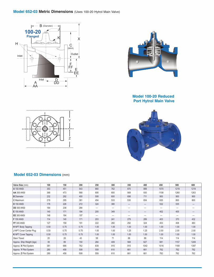
The Model 652-03 discharges to atmosphere from a teein the pump discharge header. The valve anticipatessurges caused by power failure as well as acting as astandard overpressure relief valve.
Typical ApplicationPump
Discharge ToAtmosphere
IsolationValve
Pressure Sensing Line
Discharge To System
Discharge ToAtmosphere
CLA-VAL652-03 Surge
Anticipator ValveCLA-VAL
81-02/681-02Check Valve
CLA-VAL61-02/661-02
Pump Control Valve
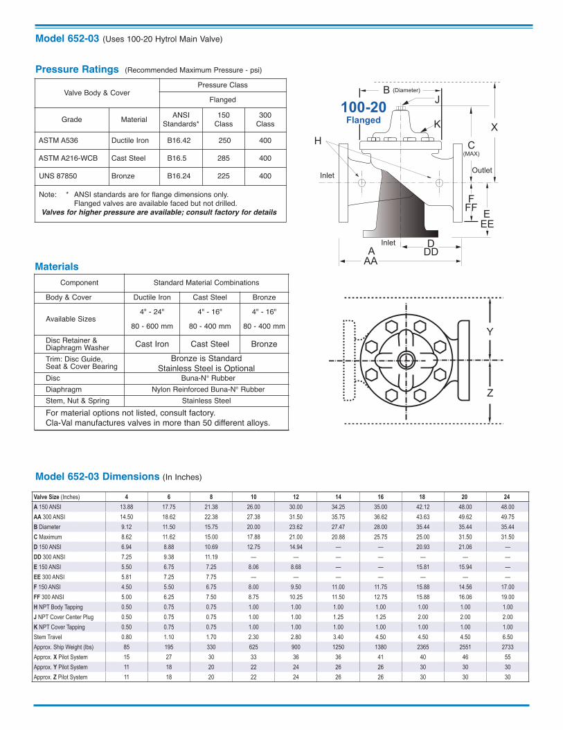
Schematic Diagram Item Description 1 100-20 Hytrol Main Valve 2 X10²F Flow Limiter 3 X101 Valve Position Indicator * 4 CK2 Isolation Valve 5 100-01 Hytrol (Reverse Flow) 6 CRL-60 Pressure Relief Control 7 CRA Pressure Reducing Control 8 X58B Restriction Tube Assembly 9 CSC Swing Check Valve 10 X42N-3 Strainer Needle Valve 11 Bell Reducer 12 Pressure Gage 13 CK2 Isolation Valve 14 CK2 Isolation Valve
*Note: X101 or X105L Accessories not available in 4" size.
Note: The remote pressure sensing line should be 3⁄4" minimum I.D. installed from the valve to the pipeline to avoid air pockets.
Note: We recommend protecting tubing and valve from freezing temperatures.
Model 652-03 (Uses 100-20 Hytrol Main Valve)
Model 652-03 Dimensions (In Inches)
Component Standard Material CombinationsBody & Cover Ductile Iron Cast Steel Bronze
Available Sizes4" - 24"
80 - 600 mm4" - 16"
80 - 400 mm4" - 16"
80 - 400 mmDisc Retainer &Diaphragm Washer Cast Iron Cast Steel BronzeTrim: Disc Guide, Seat & Cover Bearing
Bronze is StandardStainless Steel is Optional
Disc Buna-N® RubberDiaphragm Nylon Reinforced Buna-N® RubberStem, Nut & Spring Stainless SteelFor material options not listed, consult factory.Cla-Val manufactures valves in more than 50 different alloys.
Materials
Pressure Ratings (Recommended Maximum Pressure - psi)
Valve Body & CoverPressure Class
Flanged
Grade Material ANSIStandards*
150 Class
300 Class
ASTM A536 Ductile Iron B16.42 250 400
ASTM A216-WCB Cast Steel B16.5 285 400
UNS 87850 Bronze B16.24 225 400
Note: * ANSI standards are for flange dimensions only. Flanged valves are available faced but not drilled.Valves for higher pressure are available; consult factory for details
Y
Z
EE
D
E
InletDD
AA
X
100-20Flanged
F
A
C(MAX)
K
J
H
InletOutlet
FF
B (Diameter)
Valve Size (Inches) 4 6 8 10 12 14 16 18 20 24A 150 ANSI 13.88 17.75 21.38 26.00 30.00 34.25 35.00 42.12 48.00 48.00AA 300 ANSI 14.50 18.62 22.38 27.38 31.50 35.75 36.62 43.63 49.62 49.75B Diameter 9.12 11.50 15.75 20.00 23.62 27.47 28.00 35.44 35.44 35.44C Maximum 8.62 11.62 15.00 17.88 21.00 20.88 25.75 25.00 31.50 31.50D 150 ANSI 6.94 8.88 10.69 12.75 14.94 — — 20.93 21.06 —DD 300 ANSI 7.25 9.38 11.19 — — — — — — —E 150 ANSI 5.50 6.75 7.25 8.06 8.68 — — 15.81 15.94 —EE 300 ANSI 5.81 7.25 7.75 — — — — — — —F 150 ANSI 4.50 5.50 6.75 8.00 9.50 11.00 11.75 15.88 14.56 17.00FF 300 ANSI 5.00 6.25 7.50 8.75 10.25 11.50 12.75 15.88 16.06 19.00H NPT Body Tapping 0.50 0.75 0.75 1.00 1.00 1.00 1.00 1.00 1.00 1.00J NPT Cover Center Plug 0.50 0.75 0.75 1.00 1.00 1.25 1.25 2.00 2.00 2.00K NPT Cover Tapping 0.50 0.75 0.75 1.00 1.00 1.00 1.00 1.00 1.00 1.00Stem Travel 0.80 1.10 1.70 2.30 2.80 3.40 4.50 4.50 4.50 6.50Approx. Ship Weight (lbs) 85 195 330 625 900 1250 1380 2365 2551 2733Approx. X Pilot System 15 27 30 33 36 36 41 40 46 55Approx. Y Pilot System 11 18 20 22 24 26 26 30 30 30Approx. Z Pilot System 11 18 20 22 24 26 26 30 30 30
EE
D
E
InletDD
AA
X
100-20Flanged
F
A
C(MAX)
K
J
H
InletOutlet
FF
B (Diameter)
Model 652-03 Dimensions (mm)
Y
Z
Valve Size (mm) 100 150 200 250 300 350 400 450 500 600A 150 ANSI 353 451 543 660 762 870 889 1070 1219 1219AA 300 ANSI 368 473 568 695 800 908 930 1108 1260 1263B Diameter 232 292 400 508 600 698 711 900 900 900C Maximum 219 295 381 454 533 530 654 635 800 800D 150 ANSI 176 226 272 324 380 — — 532 535 —DD 300 ANSI 184 238 284 — — — — — — —E 150 ANSI 140 171 184 205 349 — — 402 405 —EE 300 ANSI 148 184 197 — — — — — — —F 150 ANSI 114 140 171 203 241 279 289 403 370 432FF 300 ANSI 127 159 191 222 260 292 324 403 408 483H NPT Body Tapping 0.50 0.75 0.75 1.00 1.00 1.00 1.00 1.00 1.00 1.00J NPT Cover Center Plug 0.50 0.75 0.75 1.00 1.00 1.25 1.25 2.00 2.00 2.00K NPT Cover Tapping 0.50 0.75 0.75 1.00 1.00 1.00 1.00 1.00 1.00 1.00Stem Travel 20 28 43 58 71 86 86 114 114 114Approx. Ship Weight (kgs) 39 89 150 284 409 568 627 681 1157 1249Approx. X Pilot System 381 686 762 839 915 915 1042 1016 1169 1397Approx. Y Pilot System 280 458 508 559 610 661 661 762 762 762Approx. Z Pilot System 280 458 508 559 610 661 661 762 762 762
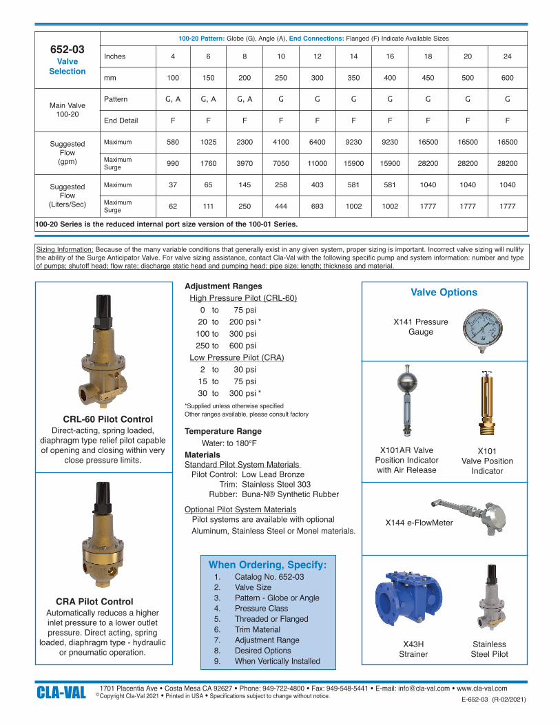
Model 652-03 Metric Dimensions (Uses 100-20 Hytrol Main Valve)
Model 100-20 ReducedPort Hytrol Main Valve
CLA-VAL 1701 Placentia Ave • Costa Mesa CA 92627 • Phone: 949-722-4800 • Fax: 949-548-5441 • E-mail: [email protected] • www.cla-val.com Copyright Cla-Val 2021 • Printed in USA • Specifications subject to change without notice.©
E-652-03 (R-02/2021)
652-03Valve
Selection
100-20 Pattern: Globe (G), Angle (A), End Connections: Flanged (F) Indicate Available Sizes
Inches 4 6 8 10 12 14 16 18 20 24
mm 100 150 200 250 300 350 400 450 500 600
Main Valve100-20
Pattern G, A G, A G, A G G G G G G G
End Detail F F F F F F F F F F
Suggested Flow (gpm)
Maximum 580 1025 2300 4100 6400 9230 9230 16500 16500 16500
MaximumSurge 990 1760 3970 7050 11000 15900 15900 28200 28200 28200
Suggested Flow
(Liters/Sec)
Maximum 37 65 145 258 403 581 581 1040 1040 1040
MaximumSurge 62 111 250 444 693 1002 1002 1777 1777 1777
100-20 Series is the reduced internal port size version of the 100-01 Series.
Sizing Information: Because of the many variable conditions that generally exist in any given system, proper sizing is important. Incorrect valve sizing will nullifythe ability of the Surge Anticipator Valve. For valve sizing assistance, contact Cla-Val with the following specific pump and system information: number and typeof pumps; shutoff head; flow rate; discharge static head and pumping head; pipe size; length; thickness and material.
Temperature Range Water: to 180°FMaterialsStandard Pilot System Materials Pilot Control: Low Lead Bronze Trim: Stainless Steel 303 Rubber: Buna-N® Synthetic RubberOptional Pilot System Materials
Pilot systems are available with optionalAluminum, Stainless Steel or Monel materials.
Adjustment RangesHigh Pressure Pilot (CRL-60)
0 to 75 psi 20 to 200 psi * 100 to 300 psi 250 to 600 psiLow Pressure Pilot (CRA)
2 to 30 psi 15 to 75 psi 30 to 300 psi *
*Supplied unless otherwise specifiedOther ranges available, please consult factoryCRL-60 Pilot Control
CRA Pilot ControlAutomatically reduces a higher inlet pressure to a lower outletpressure. Direct acting, spring
loaded, diaphragm type - hydraulicor pneumatic operation.
Direct-acting, spring loaded,diaphragm type relief pilot capableof opening and closing within very
close pressure limits.
When Ordering, Specify: 1. Catalog No. 652-03 2. Valve Size 3. Pattern - Globe or Angle 4. Pressure Class 5. Threaded or Flanged 6. Trim Material 7. Adjustment Range 8. Desired Options 9. When Vertically Installed
Valve Options
X141 PressureGauge
X101AR ValvePosition Indicatorwith Air Release
X144 e-FlowMeter
X43HStrainer
StainlessSteel Pilot
X101 Valve Position
Indicator