65.99897_8076c_p158le_180le_222le(pu )
TRANSCRIPT

Operation &Maintenance Manual
GENERATOR DIESEL ENGINE
P158LE / -1 / - 2 / -S / -IIIP180LE / -1 / -S / -IIP222LE / -1 / -S / -II
POWER UNIT DIESEL ENGINE
PU158TIPU180TIPU222TI
65.99897-8076C
FOREWORD
This manual is designed to serve as an instruction for Diesel generator engine and Power Unit engine of
DOOSAN series (P158LE /P180LE /P222LE, PU158TI/ PU180TI/ PU222TI).
The engines are 4 strokes, 2 valves per cylinder, V-type, and direct injection mode and thus, are also satisfying
with various features required as generator and power unit engine such as quiet operation, economical fuel
consumption, durability in high speed operation and so forth.
We are very confident that these engine series are quite superior to any high speed engines in economy and
efficiency. However, high performance and long life cycle will be accomplished when a proper handling and
administration of periodic inspections and maintenance should be observed. Readers are desired to know for
your reference that those kinds of maintenance matters are explained here in detail by means of figures and
diagrams.
In this manual, the following symbols are used to indicate the type of service operations to be performed.
Removal Adjustment
Installation Cleaning
Disassembly Pay close attention-Important
Reassembly Tighten to specified torque
Align the marks Use special tools of manufacturer's
Directional Indication Lubricate with oil
Inspection Lubricate with grease
Measurement
If you have any question or recommendation in connection with this manual, please do not hesitate to contact
our head office, dealers or authorized service shops near by your location for any services.
For the last, the contents of this instruction manual may be changed without prior notice for some quality
improvement. Thank you.
Doosan Infracore Co., Ltd.
Jan. 2008
CONTENTS
1. Safety Regulations & Engine Specifications
1.1. Safety regulations ............................................................................................................................... 1
1.2. Engine Specification ........................................................................................................................... 5
1.3. Engine Assembly .............................................................................................................................. 11
2. Technical Information
2.1. Engine Model and Serial Number ..................................................................................................... 19
2.2. Engines Characteristic ...................................................................................................................... 20
2.3. Troubleshooting ................................................................................................................................ 41
2.4. Operation tip ..................................................................................................................................... 51
3. Disassembly and Reassembly of Major Components
3.1. Engine Disassembly ......................................................................................................................... 52
3.2. Inspection ......................................................................................................................................... 62
3.3. Engine Reassembly .......................................................................................................................... 81
3.4. Breaking-In ....................................................................................................................................... 98
4. Commissioning and Operation
4.1. Preparations ..................................................................................................................................... 99
4.2. Starting ............................................................................................................................................. 99
4.3. Running in ...................................................................................................................................... 100
4.4. During operation ............................................................................................................................. 100
4.5. Shutting down ................................................................................................................................. 100
4.6. Maintenance and Care ................................................................................................................... 101
5. Maintenance of Major Components
5.1. Fuel Injection System ..................................................................................................................... 105
5.2. Cooling System .............................................................................................................................. 126
5.3. Lubricating System ......................................................................................................................... 129
5.4. Turbo Charger ................................................................................................................................ 131
5.5. Installation ...................................................................................................................................... 140
5.6. Air Cleaner ...................................................................................................................................... 143
5.7. Tightening Cylinder Head Bolts ...................................................................................................... 145
5.8. V-belts ............................................................................................................................................ 146
6. Special Tool List ................................................................................................................................. 149
Appendix
Parts & After Service Center
Worldwide Network
1. Safety Regulations & Engine Specifications
1.1. Safety Regulations
1.1.1. General notes
Handling diesel engines and the necessary resources is no problem when the personnel commissioned
with operation and maintenance are trained accordingly and use their common sense.
This summary is a compilation of the most important regulations, These are broken down into main
sections which contain the information necessary for preventing injury to persons, damage to property
and pollution. In addition to these regulations those dictated by the type of engine and its site are to be
observed also.
IMPORTANT :
If despite all precautions, an accident occurs, in particular through contact with
caustic acids, fuel penetrating the skin, scalding from oil, antifreeze being splashed
in the eyes etc, consult a doctor immediately.
1.1.2. Regulations designed to prevent accidents
1) During commissioning, starting and operation
Before putting the engine into operation for the first time, read the operating instructions carefully
and familiarize yourself with the “critical” points, If you are unsure, ask your DHI representative.
For reasons of safety we recommend you attach a notice to the door of the engine room
prohibiting the access of unauthorized persons and that you draw the attention of the operating
personal to the fact that they are responsible for the safety of persons who enter the engine room.
The engine must be started and operated only by authorized personnel. Ensure that the engine
cannot be started by unauthorized persons.
When the engine is running, do not get too close to the rotating parts. Wear close-fitting clothing.
Do not touch the engine with bare hands when it is warm from operation risk of bums.
Exhaust gases are toxic. Comply with the instructions for the installation of DHI Diesel engines
which are to be operated in enclosed spaces. Ensure that there is adequate ventilation and air
extraction.
Keep vicinity of engine, ladders and stairways free of oil and grease. Accidents caused by slipping
can have serious consequences.
Safety Regulations & Engine Specifications- 1 -
2) During maintenance and care
Always carry out maintenance work when the engine is switched off. If the engine has to be
maintained while it Is running, e.g. changing the elements of change-over filters, remember that
there is a risk of scalding. Do not get too close to rotating parts.
Change the oil when the engine is warm from operation.
CAUTION :
There is a rise of burns and scalding. Do not touch oil drain plug or oil filters with
bare hands.
Take into account the amount of oil in the sump. Use a vessel of sufficient size to ensure that the
oil will not overflow.
Open the coolant circuit only when the engine has cooled down. If opening while the engine is still
warm is unavoidable, comply with the instructions in the chapter “Maintenance and Care”.
Neither tighten up nor open pipes and hoses (lube oil circuit, coolant circuit and any additional
hydraulic oil circuit) during the operation. The fluids which flow out can cause injury.
Fuel is inflammable. Do not smoke or use naked lights in its vicinity. The tank must be filled only
when the engine is switched off.
When using compressed air, e.g. for cleaning the radiator, wear goggles.
Keep service products (anti-freeze) only in containers which can not be confused with drinks
containers.
Comply with the manufacturer’s instructions when handling batteries.
CAUTION :
Accumulator acid is toxic and caustic. Battery gases are explosive.
3) When carrying out checking, setting and repair work
Checking, setting and repair work must be carried out by authorized personnel only.
Use only tools which are in satisfactory condition. Worn open-end wrench slip. which could lead to
Injury.
When the engine is hanging on a crane, no-one must be allowed to stand or pass under it. Keep
lifting gear in good condition.
When working on parts which contain asbestos, comply with the notes at the end of this chapter.
When checking injectors do not put your hands under the jet of fuel. Do not inhale atomized fuel.
When working on the electrical system disconnect the battery earth cable first. Connect it up
again last in prevent short circuits.
Safety Regulations & Engine Specifications - 2 -

1.1.3. Regulations designed to prevent damage to engine and premature wear
1) Never demand more of the engine than it was designed to yield for its intended purpose.
Detailed information on this can be found in the sales literature. The injection pump must not be
adjusted without prior written permission of DHI.
2) If faults occur, find the cause immediately and have it eliminated in order to prevent more serious of
damage.
3) Use only genuine DHI spare parts. DHI will accept no responsibility for damage resulting from the
installation of other parts which are supposedly “just as good”.
4) In addition to the above, note the following points.
Never let the engine run when dry, i.e. without lube oil or coolant.
Use only DHI-approved service products (engine oil , anti-freeze and anticorrosion agent).
Pay attention to cleanliness. The Diesel fuel must be free of water. See “Maintenance and care”.
Have the engine maintained at the specified intervals.
Do not switch off the engine immediately when it is warm, but let it run without load for about 5
minutes so that temperature equalization can take place.
Never put cold coolant into an overheated engine. See “Maintenance and care”.
Do not add so much engine oil that the oil level rises above the max. marking on the dipstick. Do
not exceed the maximum permissible tilt of the engine. Serious damage to the engine may result
if these instructions are not adhered to.
Always ensure that the testing and monitoring equipment (for battery charge, oil pressure, coolant
temperature) function satisfactorily.
Comply with instructions for operation of the alternator. See “Commissioning and operation”.
Do not let the raw water pump run dry, If there is a risk of frost, drain the pump when the engine is
switched off.
1.1.4. Regulations designed to prevent pollution
1) Engine oil, filter elements, fuel filters
Take old oil only to an oil collection point.
Take strict precautions to ensure that oil does not get into the drains or into the ground. The
drinking water supply could be contaminated.
Filter elements are classed as dangerous waste and must be treated as such.
2) Coolant
Treat undiluted anti-corrosion agent and / or antifreeze as dangerous waste.
When disposing of spent coolant comply with the regulations of the relevant local authorities.
1.1.5. Notes on safety in handling used engine oil
Prolonged or repeated contact between the skin and any kind of engine oil decreases the skin.
Drying, irritation or inflammation of the skin may therefore occur. Used engine oil also contains
dangerous substances which have caused skin cancer in animal experiments. If the basic rules of
hygiene and health and safety at work are observed, health risks are not to the expected as a result of
handling used engine oil.
Safety Regulations & Engine Specifications- 3 -
Health precautions :
Avoid prolonged or repeated skin contact with used engine oil.
Protect your skin by means of suitable agents (creams etc.) or wear protective gloves.
Clean skin which has been in contact with engine oil.
- Wash thoroughly with soap and water, A nailbrush is an effective aid.
- Certain products make it easier to clean your hands.
- Do not use petrol, Diesel fuel, gas oil, thinners or solvents as washing agents.
After washing apply a fatty skin cream to the skin.
Change oil-soaked clothing and shoes.
Do not put oily rags into your pockets.
Ensure that used engine oil is disposed of properly.
- Engine oil can endanger the water supply -
For this reason do not let engine oil get into the ground, waterways, the drains or the sewers.
Violations are punishable.
Collect and dispose of used engine oil carefully. For information on collection points please contact the
seller, the supplier or the local authorities.
1.1.6. General repair instructions
1. Before performing service operation, disconnect the grounding cable from the battery for reducing
the chance of cable damage and burning due to short-circuiting.
2. Use covers for preventing the components from damage or pollution.
3. Engine oil and anti-freeze solution must be handled with reasonable care as they cause paint
damage.
4. The use of proper tools and special tools where specified is important to efficient and reliable service
operation.
5. Use genuine DOOSAN parts necessarily.
6. Used cotter pins, gaskets, O-rings, oil seals, lock washer and self-lock nuts should be discarded and
new ones should be prepared for installation as normal function of the parts can not be maintained if
these parts are reused.
7. To facilitate proper and smooth reassemble operation, keep disassembled parts neatly in groups.
Keeping fixing bolts and nut separate is very important as they vary in hardness and design
depending on position of installation.
8. Clean the parts before inspection or reassembly. Also clean oil ports, etc. using compressed air to
make certain they are free from restrictions.
9. Lubricate rotating and sliding faces of parts with oil or grease before installation.
10. When necessary, use a sealer on gaskets to prevent leakage.
11. Carefully observe all specifications for bolts and nuts torques.
12. When service operation is completed, make a final check to be sure service has been done
property.
Safety Regulations & Engine Specifications - 4 -
1.2. Engine Specification
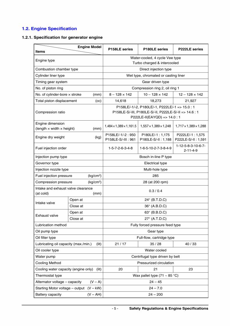
1.2.1. Specification for generator engine
Engine ModelItems
P158LE series P180LE series P222LE series
Engine typeWater-cooled, 4 cycle Vee type
Turbo charged & intercooled
Combustion chamber type Direct injection type
Cylinder liner type Wet type, chromated or casting liner
Timing gear system Gear driven type
No. of piston ring Compression ring 2, oil ring 1
No. of cylinder-bore × stroke (mm) 8 – 128 × 142 10 – 128 × 142 12 – 128 × 142
Total piston displacement (cc) 14,618 18,273 21,927
Compression ratio
P158LE/-1/-2, P180LE/-1, P222LE/-1 => 15.0 : 1
P158LE-S/-III, P180LE-S/-II, P222LE-S/-II => 14.6 : 1
P222LE-II(EAYQD) => 14.0 : 1
Engine dimension
(length × width × height) (mm)1,484 × 1,389 × 1,161.5 1,557 × 1,389 × 1,248 1,717 × 1,389 × 1,288
Engine dry weight (kg)P158LE/-1/-2 : 950P158LE-S/-III : 961
P180LE/-1 : 1,175P180LE-S/-II : 1,188
P222LE/-1 : 1,575P222LE-S/-II : 1,591
Fuel injection order 1-5-7-2-6-3-4-8 1-6-5-10-2-7-3-8-4-91-12-5-8-3-10-6-7-
2-11-4-9
Injection pump type Bosch in-line P type
Governor type Electrical type
Injection nozzle type Multi-hole type
Fuel injection pressure (kg/cm2) 285
Compression pressure (kg/cm2) 28 (at 200 rpm)
Intake and exhaust valve clearance (at cold) (mm)
0.3 / 0.4
Intake valveOpen at 24° (B.T.D.C)
Close at 36° (A.B.D.C)
Exhaust valveOpen at 63° (B.B.D.C)
Close at 27° (A.T.D.C)
Lubrication method Fully forced pressure feed type
Oil pump type Gear type
Oil filter type Full-flow, cartridge type
Lubricating oil capacity (max./min.) (lit) 21 / 17 35 / 28 40 / 33
Oil cooler type Water cooled
Water pump Centrifugal type driven by belt
Cooling Method Pressurized circulation
Cooling water capacity (engine only) (lit) 20 21 23
Thermostat type Wax pallet type (71 ~ 85 °C)
Alternator voltage – capacity (V – A) 24 – 45
Starting Motor voltage – output (V – kW) 24 – 7.0
Battery capacity (V – AH) 24 – 200
Safety Regulations & Engine Specifications- 5 -
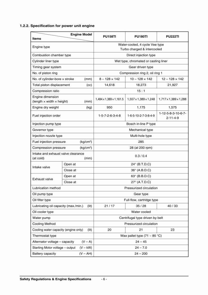
1.2.2. Specification for power unit engine
Engine ModelItems
PU158TI PU180TI PU222TI
Engine typeWater-cooled, 4 cycle Vee type
Turbo charged & intercooled
Combustion chamber type Direct injection type
Cylinder liner type Wet type, chromated or casting liner
Timing gear system Gear driven type
No. of piston ring Compression ring 2, oil ring 1
No. of cylinder-bore × stroke (mm) 8 – 128 × 142 10 – 128 × 142 12 – 128 × 142
Total piston displacement (cc) 14,618 18,273 21,927
Compression ratio 15 : 1
Engine dimension
(length × width × height) (mm)1,484 × 1,389 × 1,161.5 1,557 × 1,389 × 1,248 1,717 × 1,389 × 1,288
Engine dry weight (kg) 950 1,175 1,575
Fuel injection order 1-5-7-2-6-3-4-8 1-6-5-10-2-7-3-8-4-91-12-5-8-3-10-6-7-
2-11-4-9
Injection pump type Bosch in-line P type
Governor type Mechanical type
Injection nozzle type Multi-hole type
Fuel injection pressure (kg/cm2) 285
Compression pressure (kg/cm2) 28 (at 200 rpm)
Intake and exhaust valve clearance
(at cold) (mm)0.3 / 0.4
Intake valveOpen at 24° (B.T.D.C)
Close at 36° (A.B.D.C)
Exhaust valveOpen at 63° (B.B.D.C)
Close at 27° (A.T.D.C)
Lubrication method Pressurized circulation
Oil pump type Gear type
Oil filter type Full-flow, cartridge type
Lubricating oil capacity (max./min.) (lit) 21 / 17 35 / 28 40 / 33
Oil cooler type Water cooled
Water pump Centrifugal type driven by belt
Cooling Method Pressurized circulation
Cooling water capacity (engine only) (lit) 20 21 23
Thermostat type Wax pallet type (71 ~ 85 °C)
Alternator voltage – capacity (V – A) 24 – 45
Starting Motor voltage – output (V – kW) 24 – 7.0
Battery capacity (V – AH) 24 – 200
Safety Regulations & Engine Specifications - 6 -
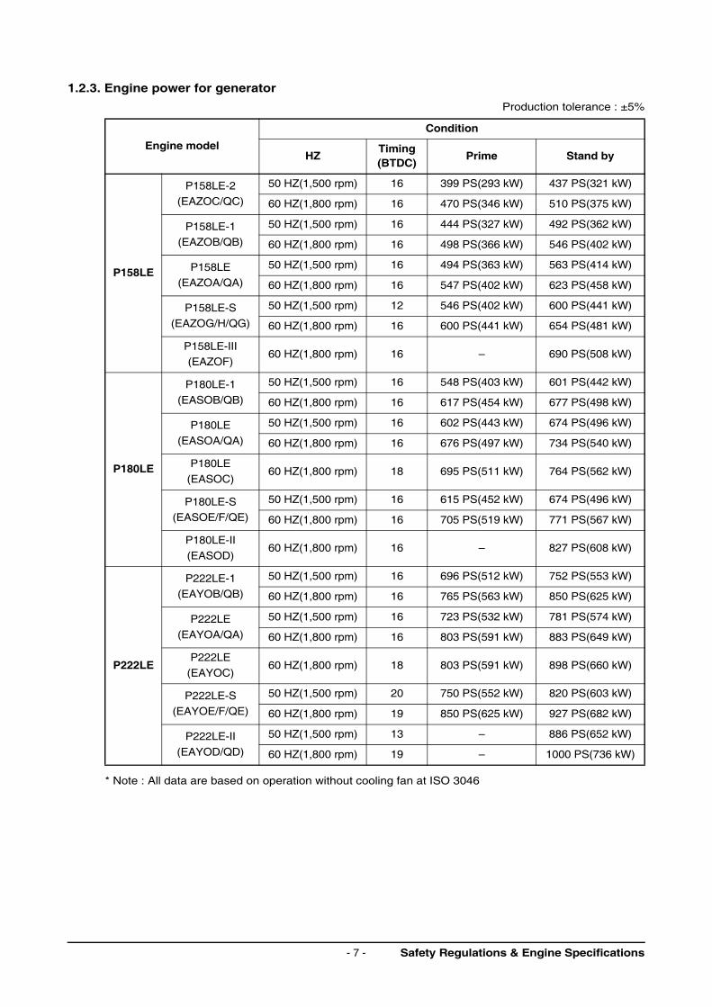
1.2.3. Engine power for generator
Production tolerance : ±5%
* Note : All data are based on operation without cooling fan at ISO 3046
Engine model
Condition
HZTiming(BTDC)
Prime Stand by
P158LE
P158LE-2
(EAZOC/QC)
50 HZ(1,500 rpm) 16 399 PS(293 kW) 437 PS(321 kW)
60 HZ(1,800 rpm) 16 470 PS(346 kW) 510 PS(375 kW)
P158LE-1
(EAZOB/QB)
50 HZ(1,500 rpm) 16 444 PS(327 kW) 492 PS(362 kW)
60 HZ(1,800 rpm) 16 498 PS(366 kW) 546 PS(402 kW)
P158LE(EAZOA/QA)
50 HZ(1,500 rpm) 16 494 PS(363 kW) 563 PS(414 kW)
60 HZ(1,800 rpm) 16 547 PS(402 kW) 623 PS(458 kW)
P158LE-S
(EAZOG/H/QG)
50 HZ(1,500 rpm) 12 546 PS(402 kW) 600 PS(441 kW)
60 HZ(1,800 rpm) 16 600 PS(441 kW) 654 PS(481 kW)
P158LE-III(EAZOF)
60 HZ(1,800 rpm) 16 – 690 PS(508 kW)
P180LE
P180LE-1
(EASOB/QB)
50 HZ(1,500 rpm) 16 548 PS(403 kW) 601 PS(442 kW)
60 HZ(1,800 rpm) 16 617 PS(454 kW) 677 PS(498 kW)
P180LE(EASOA/QA)
50 HZ(1,500 rpm) 16 602 PS(443 kW) 674 PS(496 kW)
60 HZ(1,800 rpm) 16 676 PS(497 kW) 734 PS(540 kW)
P180LE
(EASOC)60 HZ(1,800 rpm) 18 695 PS(511 kW) 764 PS(562 kW)
P180LE-S(EASOE/F/QE)
50 HZ(1,500 rpm) 16 615 PS(452 kW) 674 PS(496 kW)
60 HZ(1,800 rpm) 16 705 PS(519 kW) 771 PS(567 kW)
P180LE-II
(EASOD)60 HZ(1,800 rpm) 16 – 827 PS(608 kW)
P222LE
P222LE-1
(EAYOB/QB)
50 HZ(1,500 rpm) 16 696 PS(512 kW) 752 PS(553 kW)
60 HZ(1,800 rpm) 16 765 PS(563 kW) 850 PS(625 kW)
P222LE
(EAYOA/QA)
50 HZ(1,500 rpm) 16 723 PS(532 kW) 781 PS(574 kW)
60 HZ(1,800 rpm) 16 803 PS(591 kW) 883 PS(649 kW)
P222LE
(EAYOC)60 HZ(1,800 rpm) 18 803 PS(591 kW) 898 PS(660 kW)
P222LE-S(EAYOE/F/QE)
50 HZ(1,500 rpm) 20 750 PS(552 kW) 820 PS(603 kW)
60 HZ(1,800 rpm) 19 850 PS(625 kW) 927 PS(682 kW)
P222LE-II
(EAYOD/QD)
50 HZ(1,500 rpm) 13 – 886 PS(652 kW)
60 HZ(1,800 rpm) 19 – 1000 PS(736 kW)
Safety Regulations & Engine Specifications- 7 -
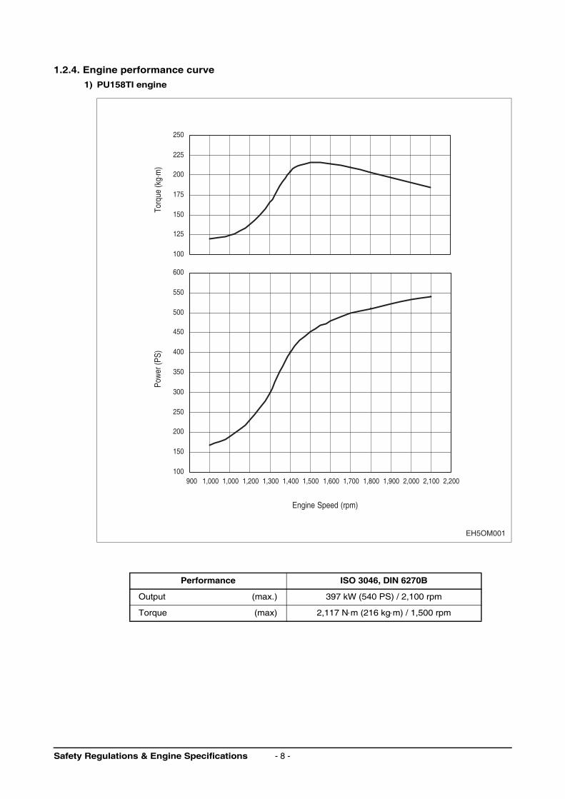
1.2.4. Engine performance curve
1) PU158TI engine
Performance ISO 3046, DIN 6270B
Output (max.) 397 kW (540 PS) / 2,100 rpm
Torque (max) 2,117 N⋅m (216 kg⋅m) / 1,500 rpm
100
125
150
175
200
225
250
Torq
ue (k
g.m
)
Engine Speed (rpm)
100
150
200
250
300
350
400
450
500
550
600
Pow
er (P
S)
EH5OM001
900 1,000 1,000 1,200 1,300 1,400 1,500 1,600 1,700 1,800 1,900 2,000 2,100 2,200
Safety Regulations & Engine Specifications - 8 -
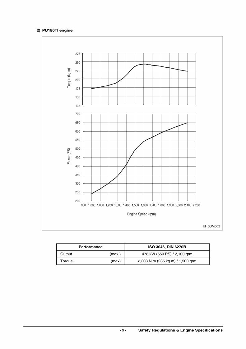
2) PU180TI engine
Performance ISO 3046, DIN 6270B
Output (max.) 478 kW (650 PS) / 2,100 rpm
Torque (max) 2,303 N⋅m (235 kg⋅m) / 1,500 rpm
125
150
175
200
225
250
275
Torq
ue (k
g.m
)
Engine Speed (rpm)
200
250
300
350
400
450
500
550
600
650
700
Pow
er (P
S)
EH5OM002
900 1,000 1,000 1,200 1,300 1,400 1,500 1,600 1,700 1,800 1,900 2,000 2,100 2,200
Safety Regulations & Engine Specifications- 9 -
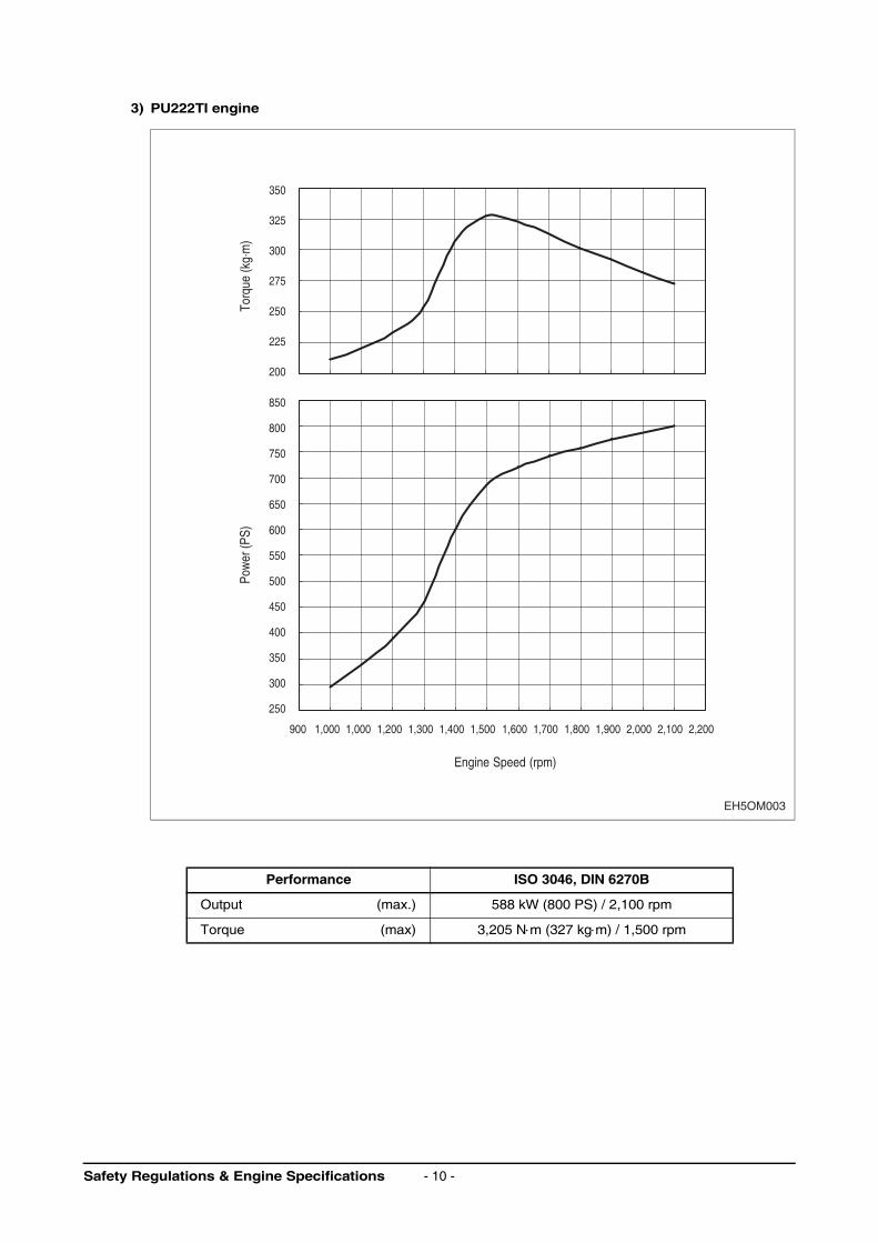
3) PU222TI engine
Performance ISO 3046, DIN 6270B
Output (max.) 588 kW (800 PS) / 2,100 rpm
Torque (max) 3,205 N⋅m (327 kg⋅m) / 1,500 rpm
200
225
250
275
300
325
350
Torq
ue (k
g.m
)
900 1,000 1,000 1,200 1,300 1,400 1,500 1,600 1,700 1,800 1,900 2,000 2,100 2,200
Engine Speed (rpm)
250
400
350
300
450
500
550
600
650
700
750
800
850
Pow
er (P
S)
EH5OM003
Safety Regulations & Engine Specifications - 10 -
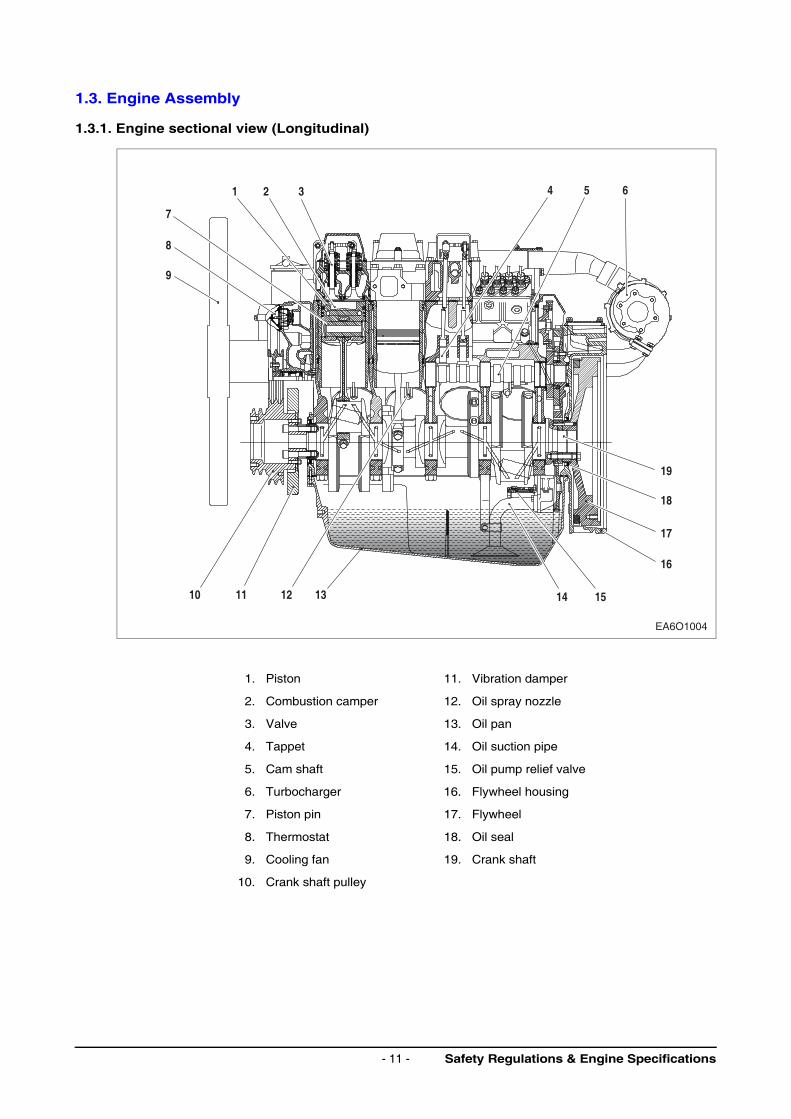
1.3. Engine Assembly
1.3.1. Engine sectional view (Longitudinal)
1. Piston 11. Vibration damper
2. Combustion camper 12. Oil spray nozzle
3. Valve 13. Oil pan
4. Tappet 14. Oil suction pipe
5. Cam shaft 15. Oil pump relief valve
6. Turbocharger 16. Flywheel housing
7. Piston pin 17. Flywheel
8. Thermostat 18. Oil seal
9. Cooling fan 19. Crank shaft
10. Crank shaft pulley
9
8
7
1 2 3 4 5 6
12 13 14 15
16
17
18
19
1110
EA6O1004
Safety Regulations & Engine Specifications- 11 -
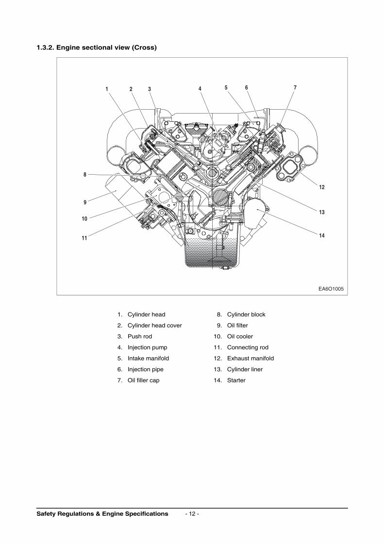
1.3.2. Engine sectional view (Cross)
1. Cylinder head 8. Cylinder block
2. Cylinder head cover 9. Oil filter
3. Push rod 10. Oil cooler
4. Injection pump 11. Connecting rod
5. Intake manifold 12. Exhaust manifold
6. Injection pipe 13. Cylinder liner
7. Oil filler cap 14. Starter
1 2
8
9
10
12
13
1411
3 4 5 6 7
EA6O1005
Safety Regulations & Engine Specifications - 12 -
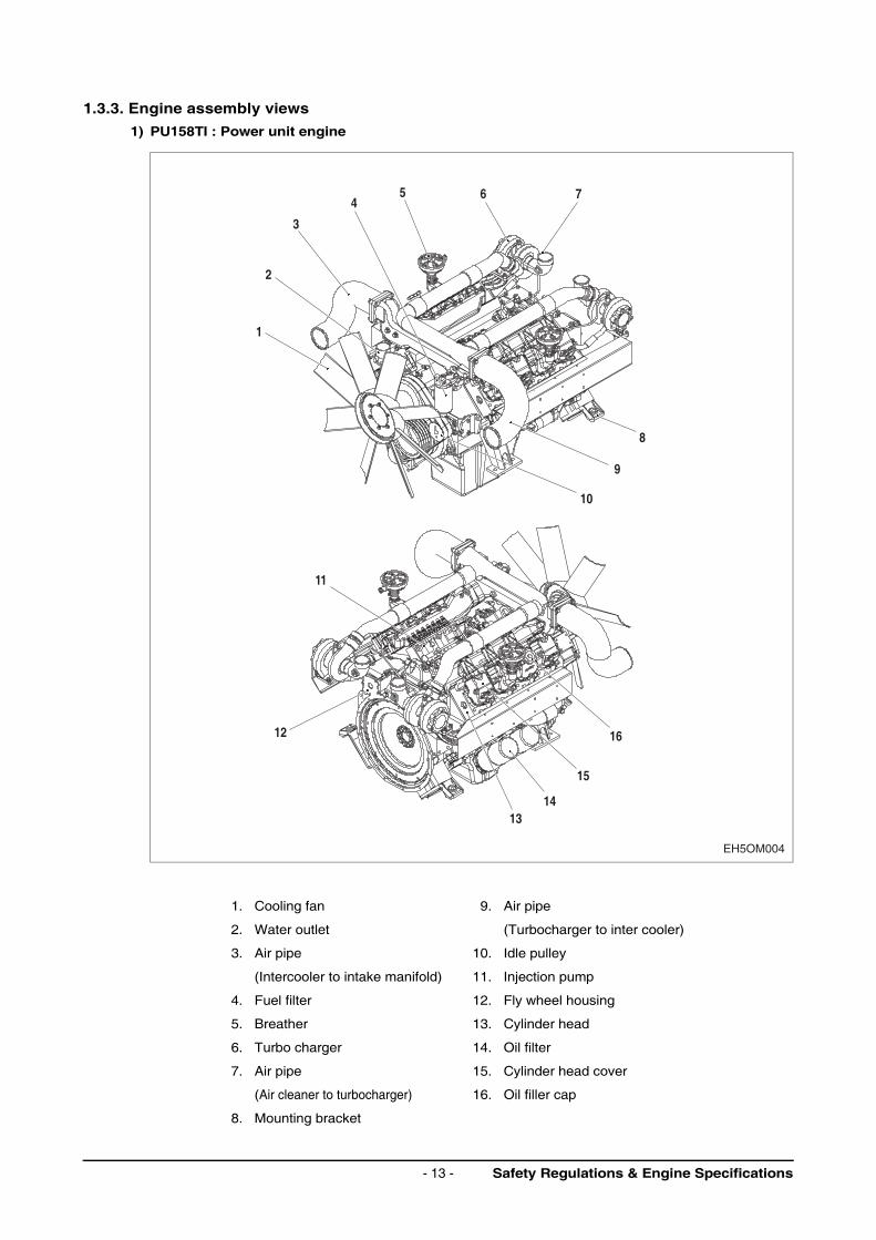
1.3.3. Engine assembly views
1) PU158TI : Power unit engine
1. Cooling fan 9. Air pipe
2. Water outlet (Turbocharger to inter cooler)
3. Air pipe 10. Idle pulley
(Intercooler to intake manifold) 11. Injection pump
4. Fuel filter 12. Fly wheel housing
5. Breather 13. Cylinder head
6. Turbo charger 14. Oil filter
7. Air pipe 15. Cylinder head cover
(Air cleaner to turbocharger) 16. Oil filler cap
8. Mounting bracket
1
2
3
45 6 7
8
9
10
15
1413
12
11
16
EH5OM004
Safety Regulations & Engine Specifications- 13 -

2) PU180TI : Power unit engine
1. Cooling fan 9. Air pipe
2. Water outlet (Turbocharger to inter cooler)
3. Air pipe 10. Starter
(Intercooler to intake manifold) 11. Idle pulley
4. Fuel filter 12. Injection pump
5. Breather 13. Fly wheel housing
6. Turbo charger 14. Cylinder head
7. Air pipe 15. Oil filter
(Air cleaner to turbocharger) 16. Oil filler cap
8. Mounting bracket 17. Cylinder head cover
1
2
3
45 6 7
8
910
15
14
13
12
11
16
17
EH5OM005
Safety Regulations & Engine Specifications - 14 -
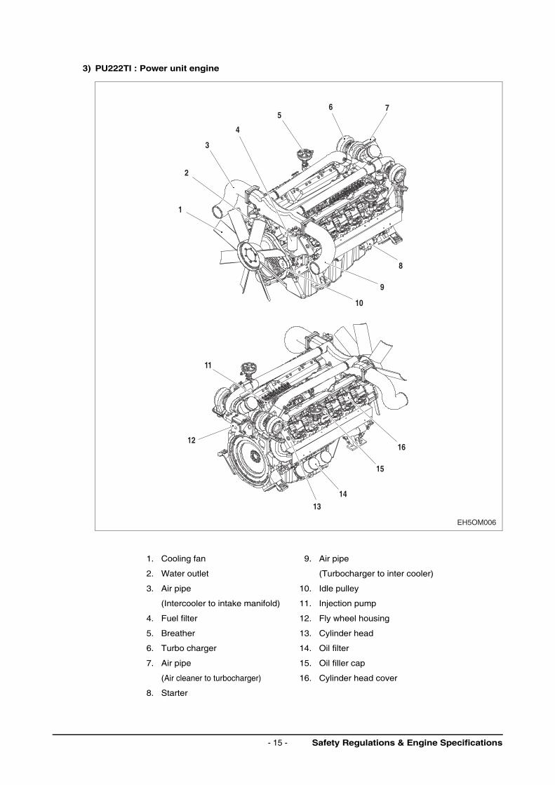
3) PU222TI : Power unit engine
1. Cooling fan 9. Air pipe
2. Water outlet (Turbocharger to inter cooler)
3. Air pipe 10. Idle pulley
(Intercooler to intake manifold) 11. Injection pump
4. Fuel filter 12. Fly wheel housing
5. Breather 13. Cylinder head
6. Turbo charger 14. Oil filter
7. Air pipe 15. Oil filler cap
(Air cleaner to turbocharger) 16. Cylinder head cover
8. Starter
1
2
3
4
56 7
8
9
10
15
14
13
12
11
16
EH5OM006
Safety Regulations & Engine Specifications- 15 -
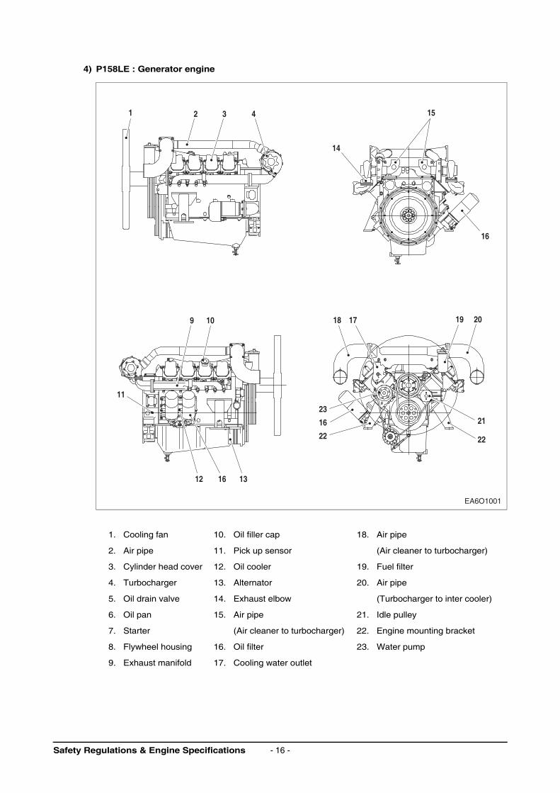
4) P158LE : Generator engine
1. Cooling fan 10. Oil filler cap 18. Air pipe
2. Air pipe 11. Pick up sensor (Air cleaner to turbocharger)
3. Cylinder head cover 12. Oil cooler 19. Fuel filter
4. Turbocharger 13. Alternator 20. Air pipe
5. Oil drain valve 14. Exhaust elbow (Turbocharger to inter cooler)
6. Oil pan 15. Air pipe 21. Idle pulley
7. Starter (Air cleaner to turbocharger) 22. Engine mounting bracket
8. Flywheel housing 16. Oil filter 23. Water pump
9. Exhaust manifold 17. Cooling water outlet
EA6O1001
151
14
9 10 18 17
23
16
22
12
11
16 13
19
16
20
22
21
2 3 4
Safety Regulations & Engine Specifications - 16 -
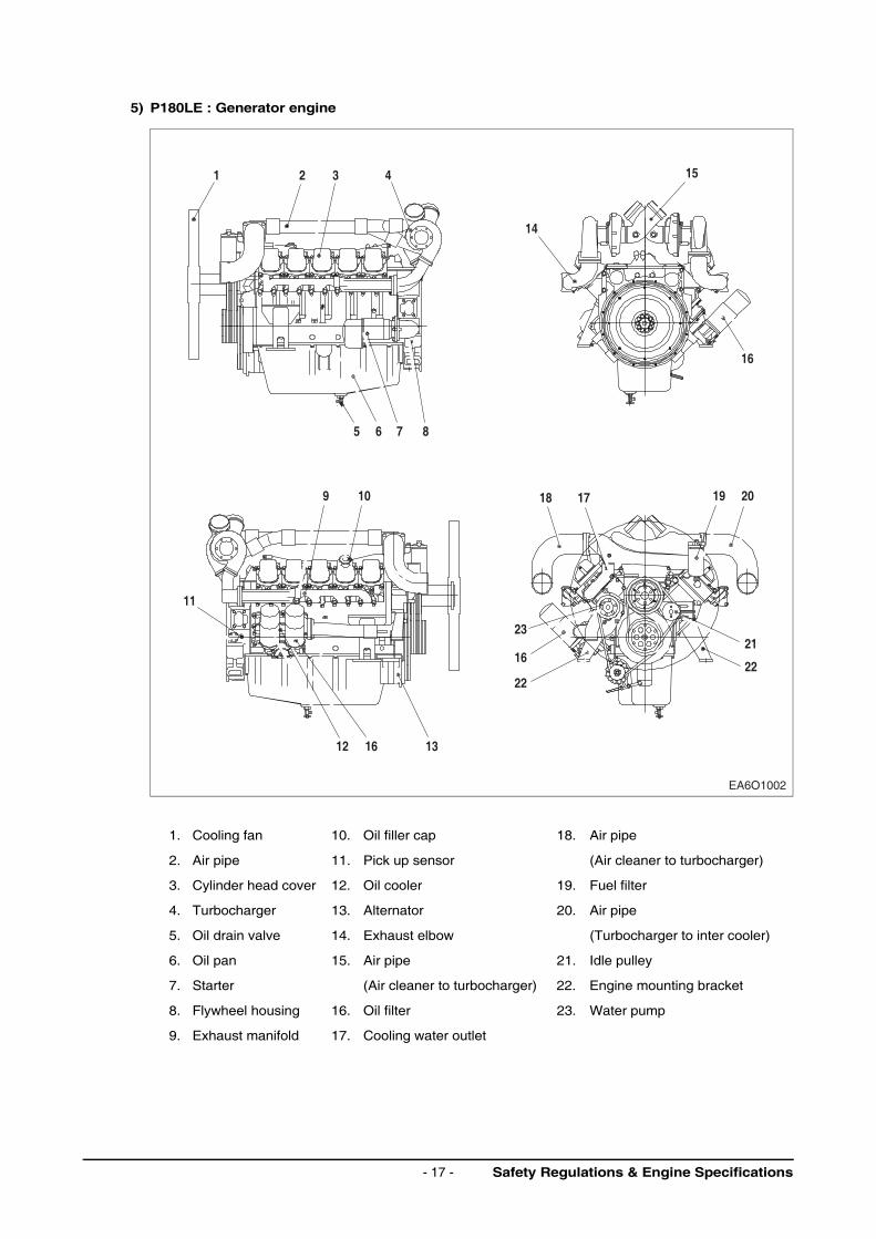
5) P180LE : Generator engine
1. Cooling fan 10. Oil filler cap 18. Air pipe
2. Air pipe 11. Pick up sensor (Air cleaner to turbocharger)
3. Cylinder head cover 12. Oil cooler 19. Fuel filter
4. Turbocharger 13. Alternator 20. Air pipe
5. Oil drain valve 14. Exhaust elbow (Turbocharger to inter cooler)
6. Oil pan 15. Air pipe 21. Idle pulley
7. Starter (Air cleaner to turbocharger) 22. Engine mounting bracket
8. Flywheel housing 16. Oil filter 23. Water pump
9. Exhaust manifold 17. Cooling water outlet
1 2 3
5
9 10
11
12 16 13
18 17 19 20
21
22
23
16
22
6 7 8
4 15
14
16
EA6O1002
Safety Regulations & Engine Specifications- 17 -
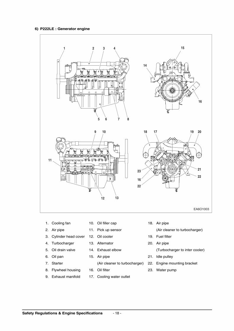
6) P222LE : Generator engine
1. Cooling fan 10. Oil filler cap 18. Air pipe
2. Air pipe 11. Pick up sensor (Air cleaner to turbocharger)
3. Cylinder head cover 12. Oil cooler 19. Fuel filter
4. Turbocharger 13. Alternator 20. Air pipe
5. Oil drain valve 14. Exhaust elbow (Turbocharger to inter cooler)
6. Oil pan 15. Air pipe 21. Idle pulley
7. Starter (Air cleaner to turbocharger) 22. Engine mounting bracket
8. Flywheel housing 16. Oil filter 23. Water pump
9. Exhaust manifold 17. Cooling water outlet
22
21
1 2 3
5 6 7 8
9 10 18 17 19 20
11
12 13
23
16
22
4 15
16
14
EA6O1003
Safety Regulations & Engine Specifications - 18 -
2. Technical Information
2.1. Engine Model and Serial Number
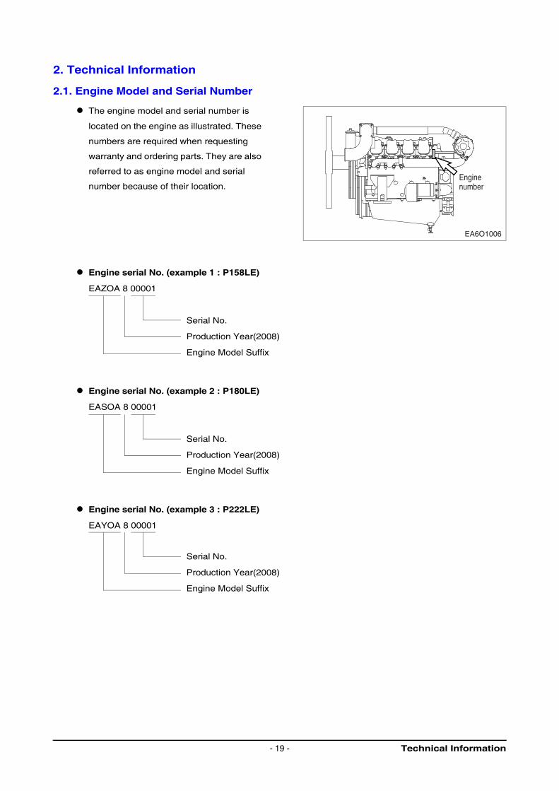
The engine model and serial number is
located on the engine as illustrated. These
numbers are required when requesting
warranty and ordering parts. They are also
referred to as engine model and serial
number because of their location.
Engine serial No. (example 1 : P158LE)
EAZOA 8 00001
Serial No.
Production Year(2008)
Engine Model Suffix
Engine serial No. (example 2 : P180LE)
EASOA 8 00001
Serial No.
Production Year(2008)
Engine Model Suffix
Engine serial No. (example 3 : P222LE)
EAYOA 8 00001
Serial No.
Production Year(2008)
Engine Model Suffix
Enginenumber
EA6O1006
Technical Information- 19 -
Engine serial No. (example 4 : PU158TI)
EAZPA 8 00001
Serial No.
Production Year(2008)
Engine Model Suffix
Engine serial No. (example 5 : PU180TI)
EASPA 8 00001
Serial No.
Production Year(2008)
Engine Model Suffix
Engine serial No. (example 6 : PU222TI)
EAYPA 8 00001
Serial No.
Production Year(2008)
Engine Model Suffix
2.2. Engines Characteristic
The generator engine(P158LE/P180LE/P222LE) and power unit engine(PU158TI/PU180TI/PU222TI)
series are V-type liquid-cooled 8/10/12-cylinder four-stroke Diesel engines with direct injection.
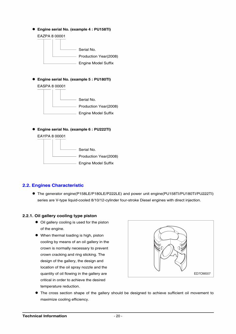
2.2.1. Oil gallery cooling type piston
Oil gallery cooling is used for the piston
of the engine.
When thermal loading is high, piston
cooling by means of an oil gallery in the
crown is normally necessary to prevent
crown cracking and ring sticking. The
design of the gallery, the design and
location of the oil spray nozzle and the
quantity of oil flowing in the gallery are
critical in order to achieve the desired
temperature reduction.
The cross section shape of the gallery should be designed to achieve sufficient oil movement to
maximize cooling efficiency.
ED7OM007
Technical Information - 20 -
2.2.2. Engine block
The cylinder block is a single piece of alloy cast iron. To increase its stiffness, it is extended to a level
below the crankshaft center line. The engine has replaceable wet cylinder liners and individual
cylinder heads with strung-in valve seat rings and replaceable valve guides.
2.2.3. Piston / Connecting rod / Crank assembly
The forged crankshaft has screwed-on counterweights. Radial seals with replaceable wearing rings
on crankshaft and flywheel are provided to seal the crankcase penetrations.
The connecting rods are die-forged, diagonally split and can be removed through the top of the
cylinders together with the pistons. Crankshaft and connecting rods run in steel-backed lead bronze
ready-to fit type bearings.
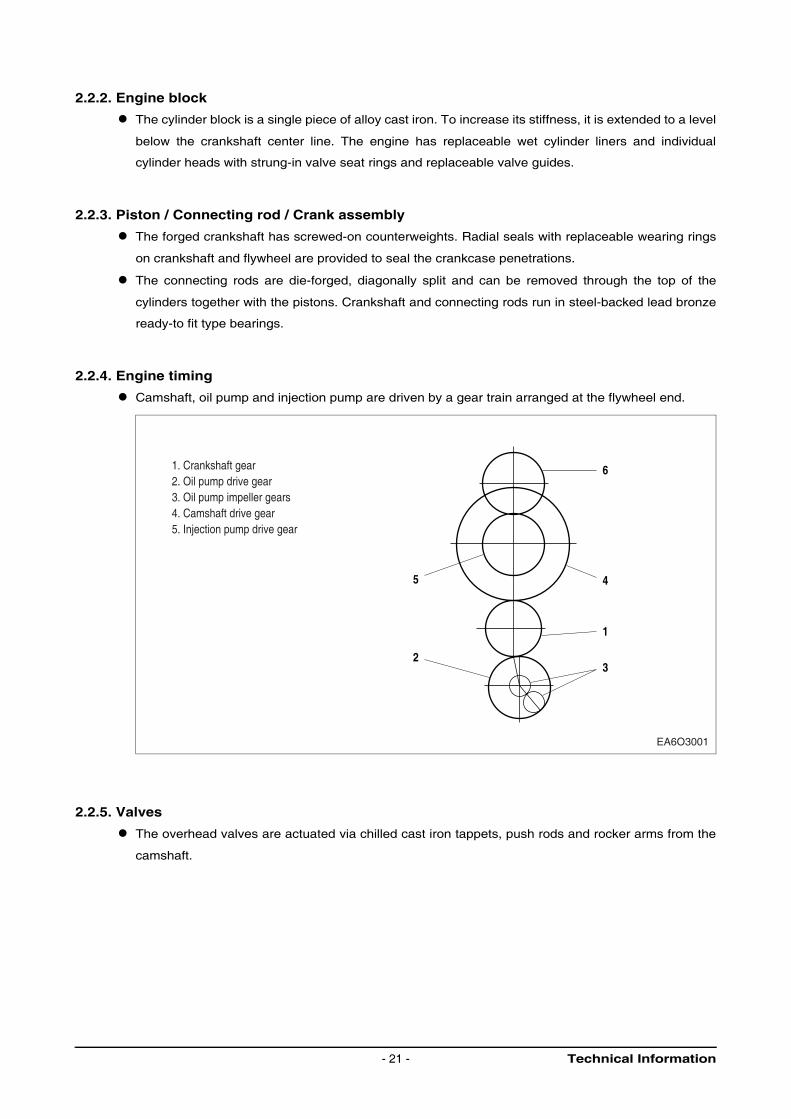
2.2.4. Engine timing
Camshaft, oil pump and injection pump are driven by a gear train arranged at the flywheel end.
2.2.5. Valves
The overhead valves are actuated via chilled cast iron tappets, push rods and rocker arms from the
camshaft.
5
2
6
1
3
4
EA6O3001
1. Crankshaft gear2. Oil pump drive gear3. Oil pump impeller gears4. Camshaft drive gear5. Injection pump drive gear
Technical Information- 21 -
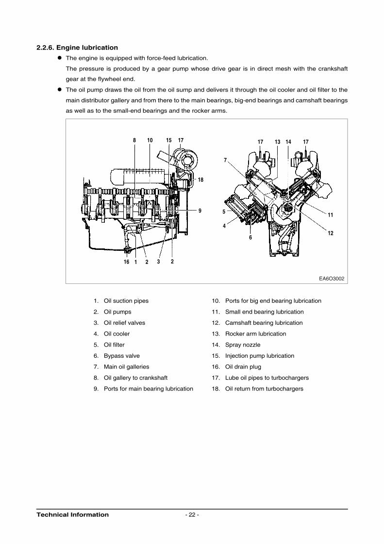
2.2.6. Engine lubrication
The engine is equipped with force-feed lubrication.
The pressure is produced by a gear pump whose drive gear is in direct mesh with the crankshaft
gear at the flywheel end.
The oil pump draws the oil from the oil sump and delivers it through the oil cooler and oil filter to the
main distributor gallery and from there to the main bearings, big-end bearings and camshaft bearings
as well as to the small-end bearings and the rocker arms.
1. Oil suction pipes 10. Ports for big end bearing lubrication
2. Oil pumps 11. Small end bearing lubrication
3. Oil relief valves 12. Camshaft bearing lubrication
4. Oil cooler 13. Rocker arm lubrication
5. Oil filter 14. Spray nozzle
6. Bypass valve 15. Injection pump lubrication
7. Main oil galleries 16. Oil drain plug
8. Oil gallery to crankshaft 17. Lube oil pipes to turbochargers
9. Ports for main bearing lubrication 18. Oil return from turbochargers
17 13 14 17
11
124
7
6
59
18
8
16 1 2 3 2
10 15 17
EA6O3002
Technical Information - 22 -
The injection pump and the turbocharger are also connected to the engine lubricating system. The
cylinder walls and timing gears are splash-lubricated.
Each cylinder has an oil jet provided for cooling the underside of the pistons.
The lube oil is cleaned in a full-flow oil filter. Depending on the agreed extent of delivery and the
design of the engine, the lube oil circuit can be equipped with oil pressure monitors (advance
warning and cut-off function) which shut the engine down in the event of a sudden loss of pressure.
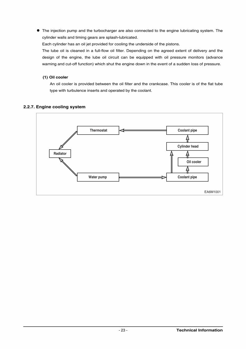
(1) Oil cooler
An oil cooler is provided between the oil filter and the crankcase. This cooler is of the flat tube
type with turbulence inserts and operated by the coolant.
2.2.7. Engine cooling system
EA6M1001
Coolant pipe
Coolant pipe
Thermostat
Water pump
Cylinder head
Oil cooler
Radiator
Technical Information- 23 -
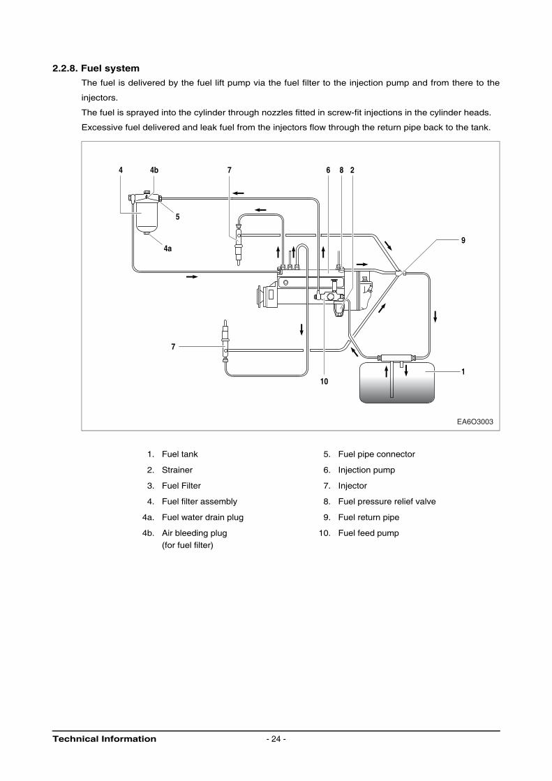
2.2.8. Fuel system
The fuel is delivered by the fuel lift pump via the fuel filter to the injection pump and from there to the
injectors.
The fuel is sprayed into the cylinder through nozzles fitted in screw-fit injections in the cylinder heads.
Excessive fuel delivered and leak fuel from the injectors flow through the return pipe back to the tank.
1. Fuel tank 5. Fuel pipe connector
2. Strainer 6. Injection pump
3. Fuel Filter 7. Injector
4. Fuel filter assembly 8. Fuel pressure relief valve
4a. Fuel water drain plug 9. Fuel return pipe
4b. Air bleeding plug
(for fuel filter)
10. Fuel feed pump
4
5
4b
4a
7
7
101
9
6 8 2
EA6O3003
Technical Information - 24 -
If Diesel fuel which contains moisture is used the injection system and the cylinder liners / pistons will be
damaged. This can be prevented to same extent by filling the tank as soon as the engine is switched off
while the fuel tank is still warm (formation of condensation is prevented). Drain moisture from storage
tanks regularly. Installation of a water trap upstream of the fuel filter is also advisable.
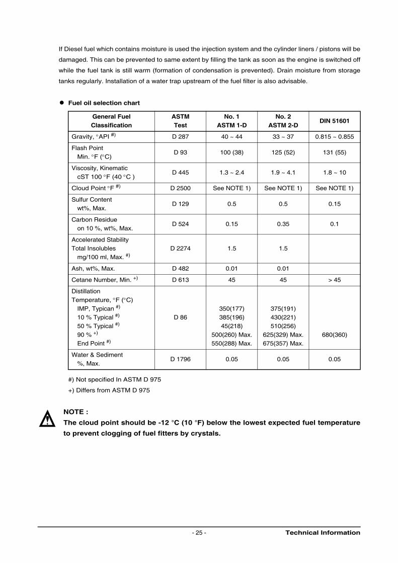
Fuel oil selection chart
#) Not specified In ASTM D 975
+) Differs from ASTM D 975
NOTE :
The cloud point should be -12 °C (10 °F) below the lowest expected fuel temperature
to prevent clogging of fuel fitters by crystals.
General FuelClassification
ASTMTest
No. 1ASTM 1-D
No. 2ASTM 2-D
DIN 51601
Gravity, °API #) D 287 40 ~ 44 33 ~ 37 0.815 ~ 0.855
Flash Point
Min. °F (°C)D 93 100 (38) 125 (52) 131 (55)
Viscosity, Kinematic
cST 100 °F (40 °C )D 445 1.3 ~ 2.4 1.9 ~ 4.1 1.8 ~ 10
Cloud Point °F #) D 2500 See NOTE 1) See NOTE 1) See NOTE 1)
Sulfur Contentwt%, Max.
D 129 0.5 0.5 0.15
Carbon Residueon 10 %, wt%, Max.
D 524 0.15 0.35 0.1
Accelerated StabilityTotal Insolubles
mg/100 ml, Max. #)D 2274 1.5 1.5
Ash, wt%, Max. D 482 0.01 0.01
Cetane Number, Min. +) D 613 45 45 > 45
Distillation
Temperature, °F (°C)
IMP, Typican #)
10 % Typical #)
50 % Typical #)
90 % +)
End Point #)
D 86350(177)385(196)
45(218)
500(260) Max.550(288) Max.
375(191)430(221)
510(256)
625(329) Max.675(357) Max.
680(360)
Water & Sediment%, Max.
D 1796 0.05 0.05 0.05
Technical Information- 25 -
2.2.9. Injection pump
No alterations must be made to the injection pump. If the lead seal is damaged the warranty on the
engine will become null and avoid.
Faults
We strongly recommend that any faults developing in the injection pump should be taken care of by
authorized specialist personnel.
Bleeding the fuel system
Bleeding the fuel filter is by releasing the bleed screws and operating the manual primer.
The suction chamber of the injection pump is continuously bled via the relief valve during operation If
the suction chamber is completely empty, e.g., when fitting a new pump, filling and bleeding it is by
actuating the manual primer.
Fuel lift pump
The fuel lift pump is operated by the injection pump camshaft via the roller tappet.
Strainer
After every 200 hours of operation the fuel strainer connected upstream of the fuel lift pump should
be cleaned.
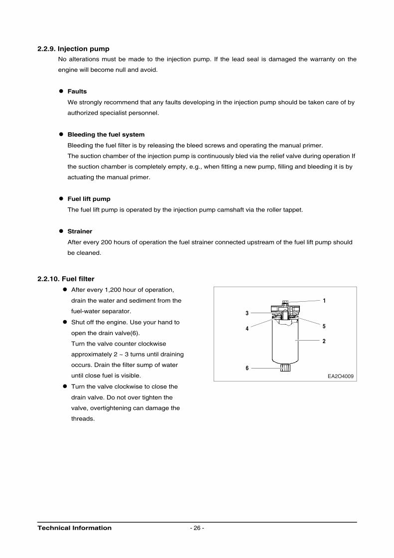
2.2.10. Fuel filter
After every 1,200 hour of operation,
drain the water and sediment from the
fuel-water separator.
Shut off the engine. Use your hand to
open the drain valve(6).
Turn the valve counter clockwise
approximately 2 ~ 3 turns until draining
occurs. Drain the filter sump of water
until close fuel is visible.
Turn the valve clockwise to close the
drain valve. Do not over tighten the
valve, overtightening can damage the
threads.
1
5
2
3
4
6EA2O4009
Technical Information - 26 -
2.2.11. Replacement of fuel filter
Clean the area around the fuel filter head(3).
Remove the fuel filter(2).
Remove the fuel filter thread adapter seal ring(4).
Use a clean lint free cloth to clean the gasket surface of the fuel filter head(3).
Install the new thread adapter seal ring(4)supplied with the new filter.
Use clean oil to lubricate the filter seal(5), and fill the new filter with clean fuel.
Install the filter on the filter head(5).
Tighten the filter until the gasket contacts the filter head surface.
Tighten the filter on additional one-half to three-fourths of a turn, on as specified by the filter
manufacturer.
NOTE :
Mechanical over tightening of the filter can distort the thread or damage the filter
element seal.
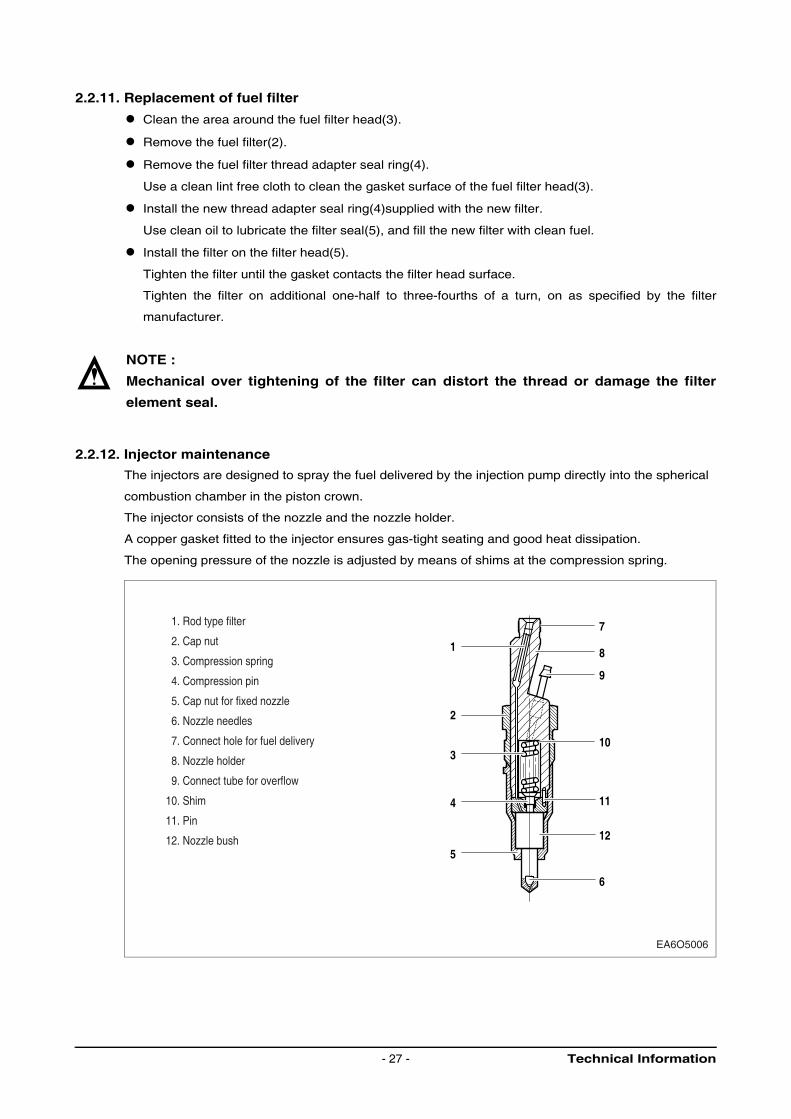
2.2.12. Injector maintenance
The injectors are designed to spray the fuel delivered by the injection pump directly into the spherical
combustion chamber in the piston crown.
The injector consists of the nozzle and the nozzle holder.
A copper gasket fitted to the injector ensures gas-tight seating and good heat dissipation.
The opening pressure of the nozzle is adjusted by means of shims at the compression spring.
8
7
9
5
4
3
11
12
6
10
2
1
EA6O5006
1. Rod type filter
2. Cap nut
3. Compression spring
4. Compression pin
5. Cap nut for fixed nozzle
6. Nozzle needles
7. Connect hole for fuel delivery
8. Nozzle holder
9. Connect tube for overflow
10. Shim
11. Pin
12. Nozzle bush
Technical Information- 27 -
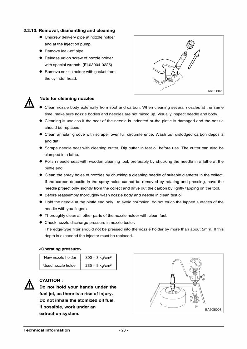
2.2.13. Removal, dismantling and cleaning
Unscrew delivery pipe at nozzle holder
and at the injection pump.
Remove leak-off pipe.
Release union screw of nozzle holder
with special wrench. (EI.03004-0225)
Remove nozzle holder with gasket from
the cylinder head.
Note for cleaning nozzles
Clean nozzle body externally from soot and carbon, When cleaning several nozzles at the same
time, make sure nozzle bodies and needles are not mixed up. Visually inspect needle and body.
Cleaning is useless if the seat of the needle is indented or the pintle is damaged and the nozzle
should be replaced.
Clean annular groove with scraper over full circumference. Wash out dislodged carbon deposits
and dirt.
Scrape needle seat with cleaning cutter, Dip cutter in test oil before use. The cutter can also be
clamped in a lathe.
Polish needle seat with wooden cleaning tool, preferably by chucking the needle in a lathe at the
pintle end.
Clean the spray holes of nozzles by chucking a cleaning needle of suitable diameter in the collect.
If the carbon deposits in the spray holes cannot be removed by rotating and pressing, have the
needle project only slightly from the collect and drive out the carbon by lightly tapping on the tool.
Before reassembly thoroughly wash nozzle body and needle in clean test oil.
Hold the needle at the pintle end only ; to avoid corrosion, do not touch the lapped surfaces of the
needle with you fingers.
Thoroughly clean all other parts of the nozzle holder with clean fuel.
Check nozzle discharge pressure in nozzle tester.
The edge-type filter should not be pressed into the nozzle holder by more than about 5mrn. If this
depth is exceeded the injector must be replaced.
<Operating pressure>
CAUTION :
Do not hold your hands under the
fuel jet, as there is a rise of injury.
Do not inhale the atomized oil fuel.
If possible, work under an
extraction system.
New nozzle holder 300 + 8 kg/cm2
Used nozzle holder 285 + 8 kg/cm2
EA6O5007
EA6O5008
Technical Information - 28 -
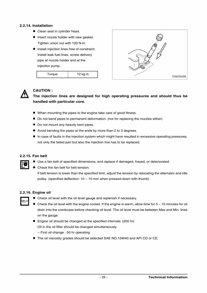
2.2.14. Installation
Clean seat in cylinder head.
Insert nozzle holder with new gasket.
Tighten union nut with 120 N⋅m.
Install injection lines free of constraint.
Install leak fuel lines. screw delivery
pipe at nozzle holder and at the
injection pump.
CAUTION :
The injection lines are designed for high operating pressures and should thus be
handled with particular core.
When mounting the pipes to the engine take care of good fitness.
Do not bend pipes to permanent deformation. (not for replacing the nozzles either)
Do not mount any heavily bent pipes.
Avoid bending the pipes at the ends by more than 2 to 3 degrees.
In case of faults in the injection system which might have resulted in excessive operating pressures,
not only the failed part but also the injection line has to be replaced.
2.2.15. Fan belt
Use a fan belt of specified dimensions, and replace if damaged, frayed, or deteriorated.
Check the fan belt for belt tension.
If belt tension is lower than the specified limit, adjust the tension by relocating the alternator and idle
pulley. (specified deflection: 10 ~ 15 mm when pressed down with thumb)
2.2.16. Engine oil
Check oil level with the oil level gauge and replenish if necessary.
Check the oil level with the engine cooled. If the engine is warm, allow time for 5 ~ 10 minutes for oil
drain into the crankcase before checking oil level. The oil level must be between Max and Min. lines
on the gauge.
Engine oil should be changed at the specified intervals. (200 hr)
Oil in the oil filter should be changed simultaneously.
– First oil change : 50 hr operating
The oil viscosity grades should be selected SAE NO.15W40 and API CD or CE.
Torque 12 kg⋅mEA6O5009
Technical Information- 29 -
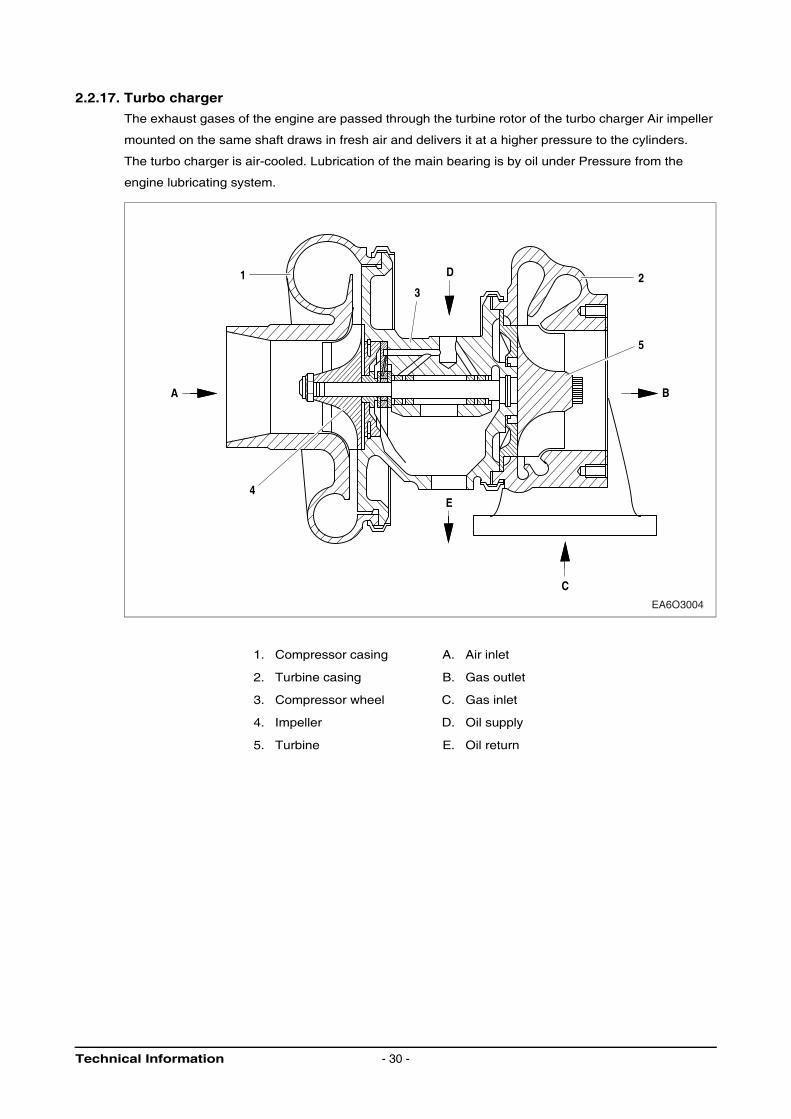
2.2.17. Turbo charger
The exhaust gases of the engine are passed through the turbine rotor of the turbo charger Air impeller
mounted on the same shaft draws in fresh air and delivers it at a higher pressure to the cylinders.
The turbo charger is air-cooled. Lubrication of the main bearing is by oil under Pressure from the
engine lubricating system.
1. Compressor casing A. Air inlet
2. Turbine casing B. Gas outlet
3. Compressor wheel C. Gas inlet
4. Impeller D. Oil supply
5. Turbine E. Oil return
C
5
32
B
E4
1
A
D
EA6O3004
Technical Information - 30 -
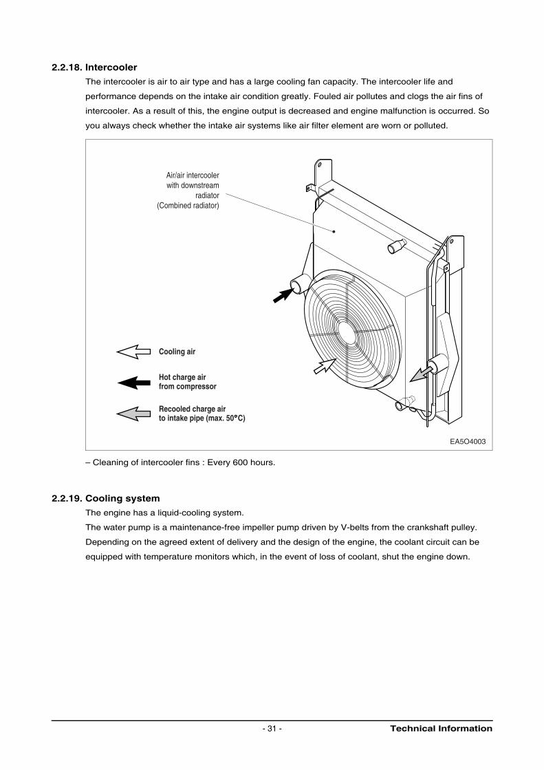
2.2.18. Intercooler
The intercooler is air to air type and has a large cooling fan capacity. The intercooler life and
performance depends on the intake air condition greatly. Fouled air pollutes and clogs the air fins of
intercooler. As a result of this, the engine output is decreased and engine malfunction is occurred. So
you always check whether the intake air systems like air filter element are worn or polluted.
– Cleaning of intercooler fins : Every 600 hours.
2.2.19. Cooling system
The engine has a liquid-cooling system.
The water pump is a maintenance-free impeller pump driven by V-belts from the crankshaft pulley.
Depending on the agreed extent of delivery and the design of the engine, the coolant circuit can be
equipped with temperature monitors which, in the event of loss of coolant, shut the engine down.
EA5O4003
Air/air intercoolerwith downstream
radiator(Combined radiator)
Cooling air
Hot charge airfrom compressor
Recooled charge airto intake pipe (max. 50 C)
Technical Information- 31 -
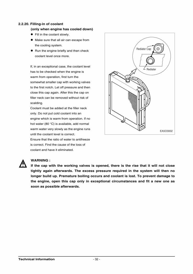
2.2.20. Filling-in of coolant
(only when engine has cooled down)
Fill in the coolant slowly.
Make sure that all air can escape from
the cooling system.
Run the engine briefly and then check
coolant level once more.
If, in an exceptional case, the coolant level
has to be checked when the engine is
warm from operation, first turn the
somewhat smaller cap with working valves
to the first notch. Let off pressure and then
close this cap again. After this the cap on
filler neck can be removed without risk of
scalding.
Coolant must be added at the filler neck
only. Do not put cold coolant into an
engine which is warm from operation. If no
hot water (80 °C) is available, add normal
warm water very slowly as the engine runs
until the coolant level is correct.
Ensure that the ratio of water to antifreeze
is correct. Find the cause of the loss of
coolant and have it eliminated.
WARNING :
If the cap with the working valves is opened, there is the rise that it will not close
tightly again afterwards. The excess pressure required in the system will then no
longer build up. Premature boiling occurs and coolant is lost. To prevent damage to
the engine, open this cap only in exceptional circumstances and fit a new one as
soon as possible afterwards.
Rediater Cap
Rediater
EA5O3002
Technical Information - 32 -
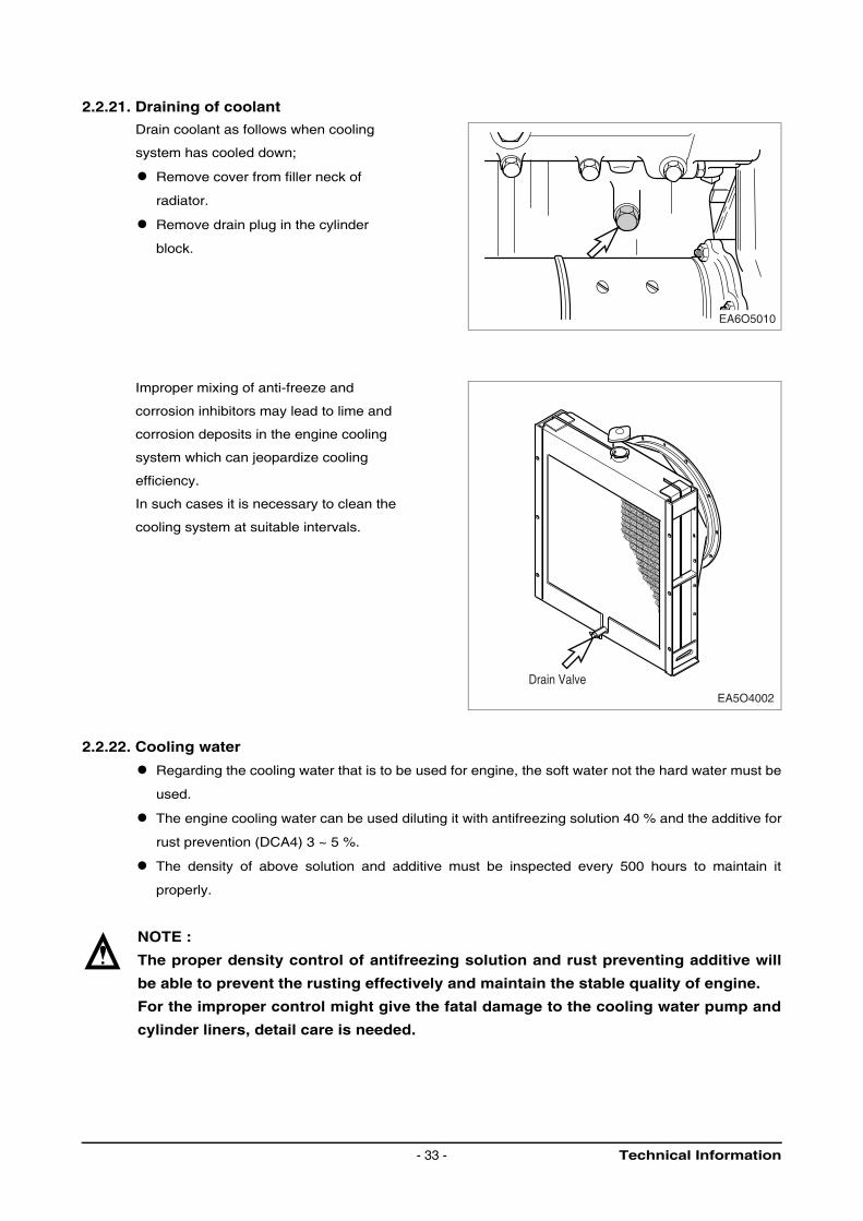
2.2.21. Draining of coolant
Drain coolant as follows when cooling
system has cooled down;
Remove cover from filler neck of
radiator.
Remove drain plug in the cylinder
block.
Improper mixing of anti-freeze and
corrosion inhibitors may lead to lime and
corrosion deposits in the engine cooling
system which can jeopardize cooling
efficiency.
In such cases it is necessary to clean the
cooling system at suitable intervals.
2.2.22. Cooling water
Regarding the cooling water that is to be used for engine, the soft water not the hard water must be
used.
The engine cooling water can be used diluting it with antifreezing solution 40 % and the additive for
rust prevention (DCA4) 3 ~ 5 %.
The density of above solution and additive must be inspected every 500 hours to maintain it
properly.
NOTE :
The proper density control of antifreezing solution and rust preventing additive will
be able to prevent the rusting effectively and maintain the stable quality of engine.
For the improper control might give the fatal damage to the cooling water pump and
cylinder liners, detail care is needed.
EA6O5010
Drain ValveEA5O4002
Technical Information- 33 -
Since P158LE/P180LE/P222LE/PU158TI/PU180TI/PU222TI cylinder liner is wet type, particularly
the cooling water control should be applied thoroughly.
The density of antifreezing solution and additive for rust prevention is able to be confirmed by the
cooling water test kit (Fleetguard CC2602M)
How to use the cooling water test kit
(1) When the cooling water temp. of engine is in the range of 10 ~ 55 °C, loosen the plug for
cooling water discharge and fill the plastic cup about a half.
NOTE :
In taking the cooling water sample, if the water in auxiliary tank were taken, it is hard
to measure the accurate density. Take the cooling water sample necessarily
loosening the cooling water discharge plug.
(2) At the state of a test paper soaked in the sampled water, after taking the paper out through
water agitation, shake off the water.
(3) Wait for about 45 sec. till the color change of test paper.
NOTE :
However, it should not elapse longer than 75 sec, and if it did, the hue would change.
(4) Make the numerical value by comparing the test paper which hue has changed with the color
list of label on storage bottle.
(5) By comparing the hue changed into yellowish green or so with the green color indication of test
paper storage bottle, confirm the density. (Then, the density indication must be in the hue range
of 33 % to 50 %).
(6) The brown at the middle of test paper and the lower pink color indication represent the additive
state for rust prevention, and the proper range is that the meeting numerical value of brown
(vertical) and pink color (horizontal) locates in the range of 0.3 to 0.8 at the color list of label on
the test paper storage bottle.
(7) In case of less than 0.3, replenish the additive for rust prevention (DCA4), and in case of more
than 0.8, pour out the cooling water about 50 % and then readjust the density after refilling with
clean fresh water.
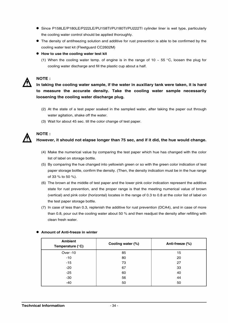
Amount of Anti-freeze in winter
AmbientTemperature (°C)
Cooling water (%) Anti-freeze (%)
Over -10
-10-15
-20
-25-30
-40
85
8073
67
6056
50
15
2027
33
4044
50
Technical Information - 34 -
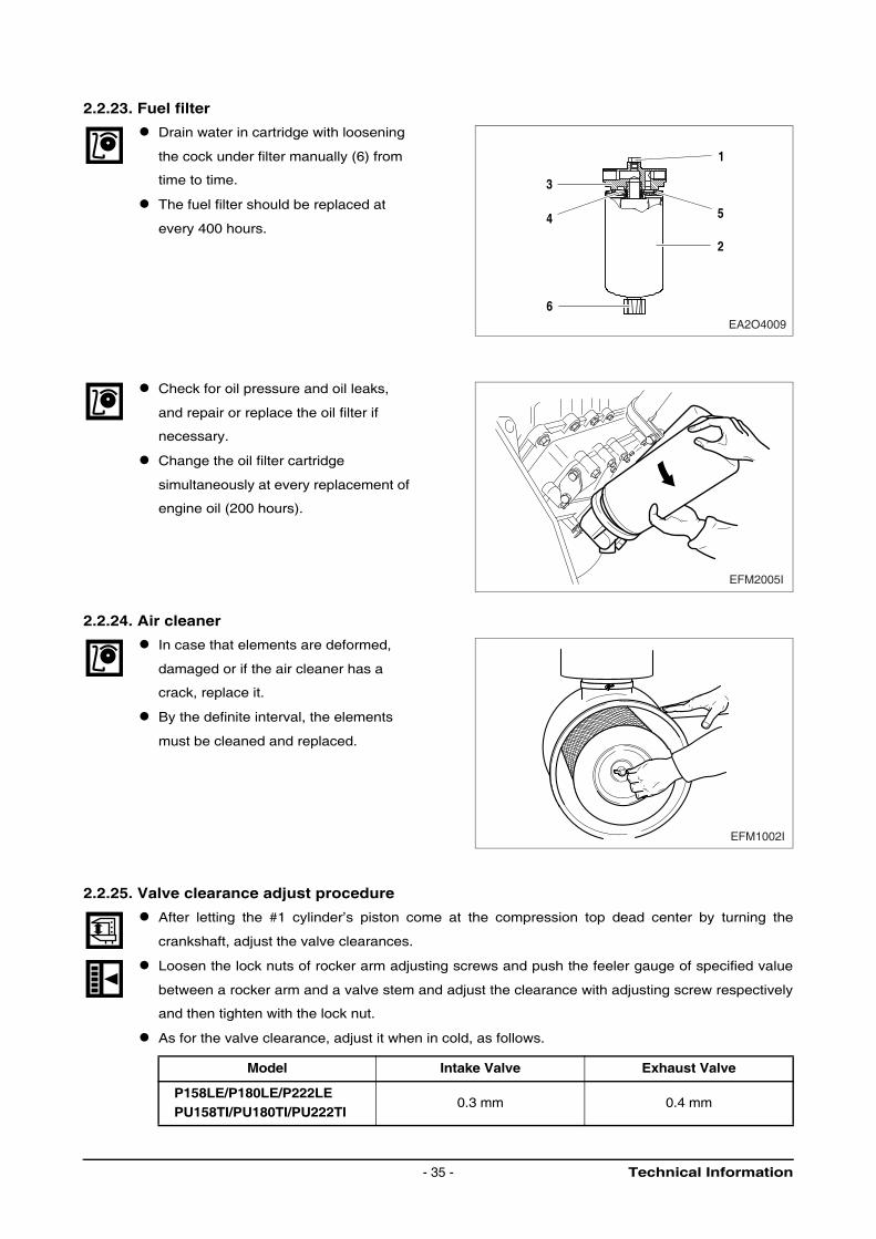
2.2.23. Fuel filter
Drain water in cartridge with loosening
the cock under filter manually (6) from
time to time.
The fuel filter should be replaced at
every 400 hours.
Check for oil pressure and oil leaks,
and repair or replace the oil filter if
necessary.
Change the oil filter cartridge
simultaneously at every replacement of
engine oil (200 hours).
2.2.24. Air cleaner
In case that elements are deformed,
damaged or if the air cleaner has a
crack, replace it.
By the definite interval, the elements
must be cleaned and replaced.
2.2.25. Valve clearance adjust procedure
After letting the #1 cylinder’s piston come at the compression top dead center by turning the
crankshaft, adjust the valve clearances.
Loosen the lock nuts of rocker arm adjusting screws and push the feeler gauge of specified value
between a rocker arm and a valve stem and adjust the clearance with adjusting screw respectively
and then tighten with the lock nut.
As for the valve clearance, adjust it when in cold, as follows.
Model Intake Valve Exhaust Valve
P158LE/P180LE/P222LEPU158TI/PU180TI/PU222TI
0.3 mm 0.4 mm
1
5
2
3
4
6EA2O4009
EFM2005I
EFM1002I
Technical Information- 35 -
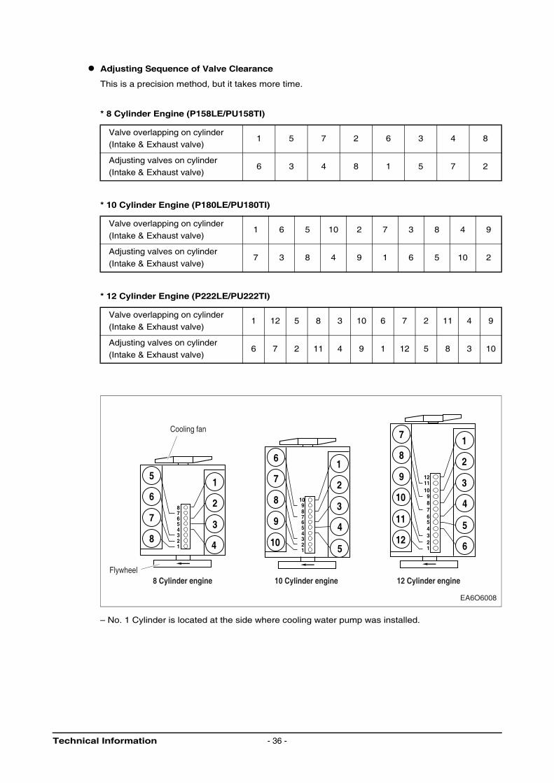
Adjusting Sequence of Valve Clearance
This is a precision method, but it takes more time.
* 8 Cylinder Engine (P158LE/PU158TI)
* 10 Cylinder Engine (P180LE/PU180TI)
* 12 Cylinder Engine (P222LE/PU222TI)
– No. 1 Cylinder is located at the side where cooling water pump was installed.
Valve overlapping on cylinder(Intake & Exhaust valve)
1 5 7 2 6 3 4 8
Adjusting valves on cylinder(Intake & Exhaust valve)
6 3 4 8 1 5 7 2
Valve overlapping on cylinder
(Intake & Exhaust valve)1 6 5 10 2 7 3 8 4 9
Adjusting valves on cylinder
(Intake & Exhaust valve)7 3 8 4 9 1 6 5 10 2
Valve overlapping on cylinder
(Intake & Exhaust valve)1 12 5 8 3 10 6 7 2 11 4 9
Adjusting valves on cylinder
(Intake & Exhaust valve)6 7 2 11 4 9 1 12 5 8 3 10
7
8
9
10
11
12
1
2
3
4
5
6
121110 9 8 7 6 5 4 3 2 1
6
7
8
9
10
1
2
3
4
5
10 9 8 7 6 5 4 3 2 1
5
6
7
8
1
2
3
4
8 7 6 5 4 3 2 1
EA6O6008
8 Cylinder engine 10 Cylinder engine 12 Cylinder engineFlywheel
Cooling fan
Technical Information - 36 -
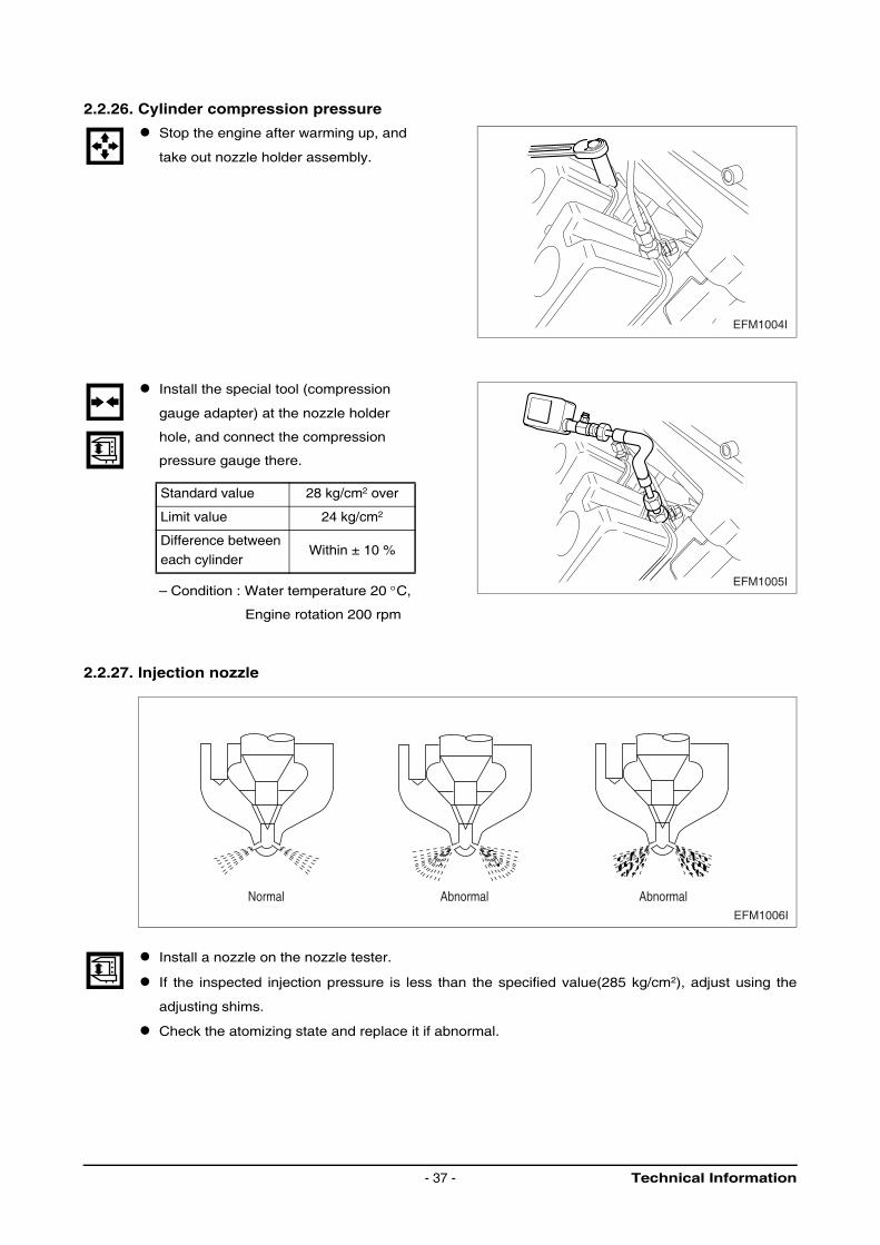
2.2.26. Cylinder compression pressure
Stop the engine after warming up, and
take out nozzle holder assembly.
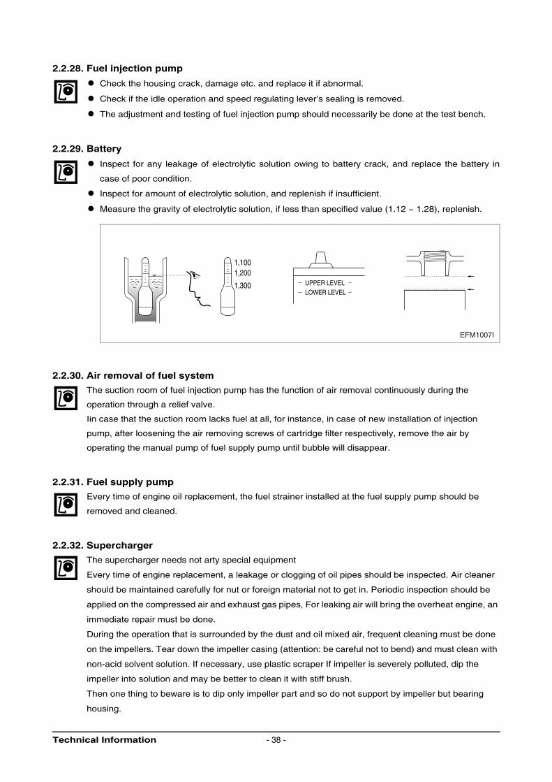
Install the special tool (compression
gauge adapter) at the nozzle holder
hole, and connect the compression
pressure gauge there.
– Condition : Water temperature 20 °C,
Engine rotation 200 rpm
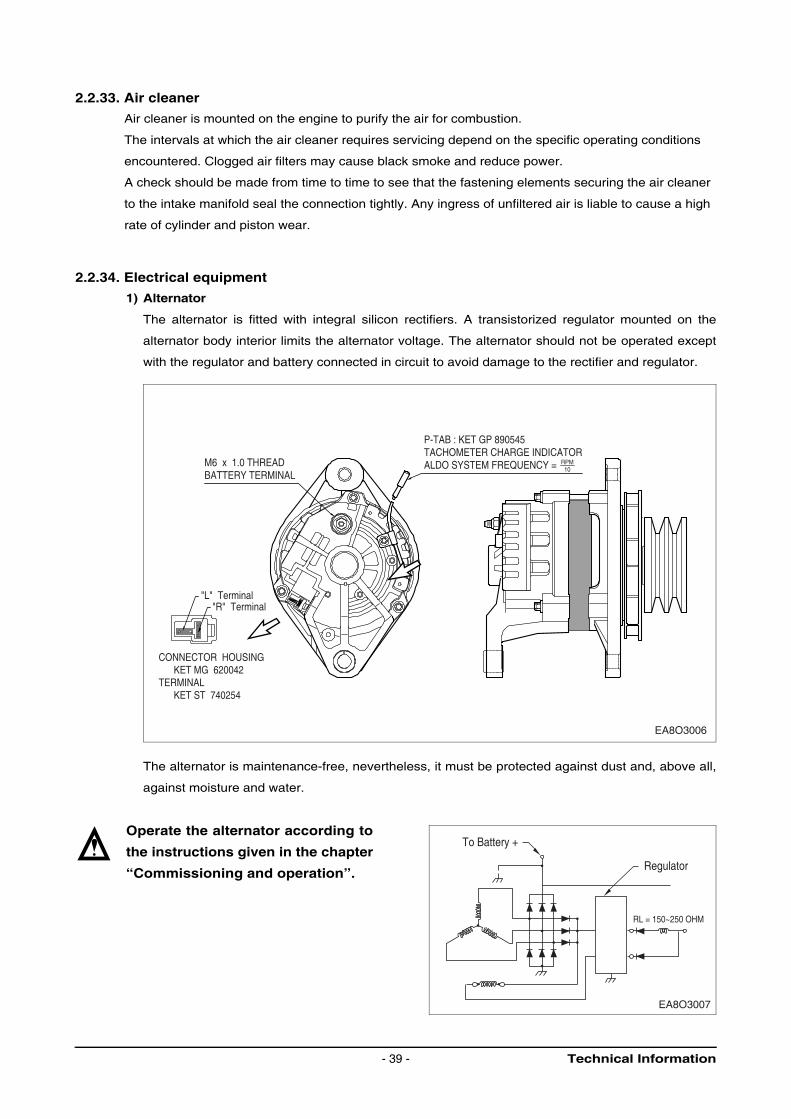
2.2.27. Injection nozzle
Install a nozzle on the nozzle tester.
If the inspected injection pressure is less than the specified value(285 kg/cm2), adjust using the
adjusting shims.
Check the atomizing state and replace it if abnormal.
Standard value 28 kg/cm2 over
Limit value 24 kg/cm2
Difference between
each cylinderWithin ± 10 %
EFM1004I
EFM1005I
EFM1006I
Normal Abnormal Abnormal
Technical Information- 37 -
2.2.28. Fuel injection pump
Check the housing crack, damage etc. and replace it if abnormal.
Check if the idle operation and speed regulating lever’s sealing is removed.
The adjustment and testing of fuel injection pump should necessarily be done at the test bench.
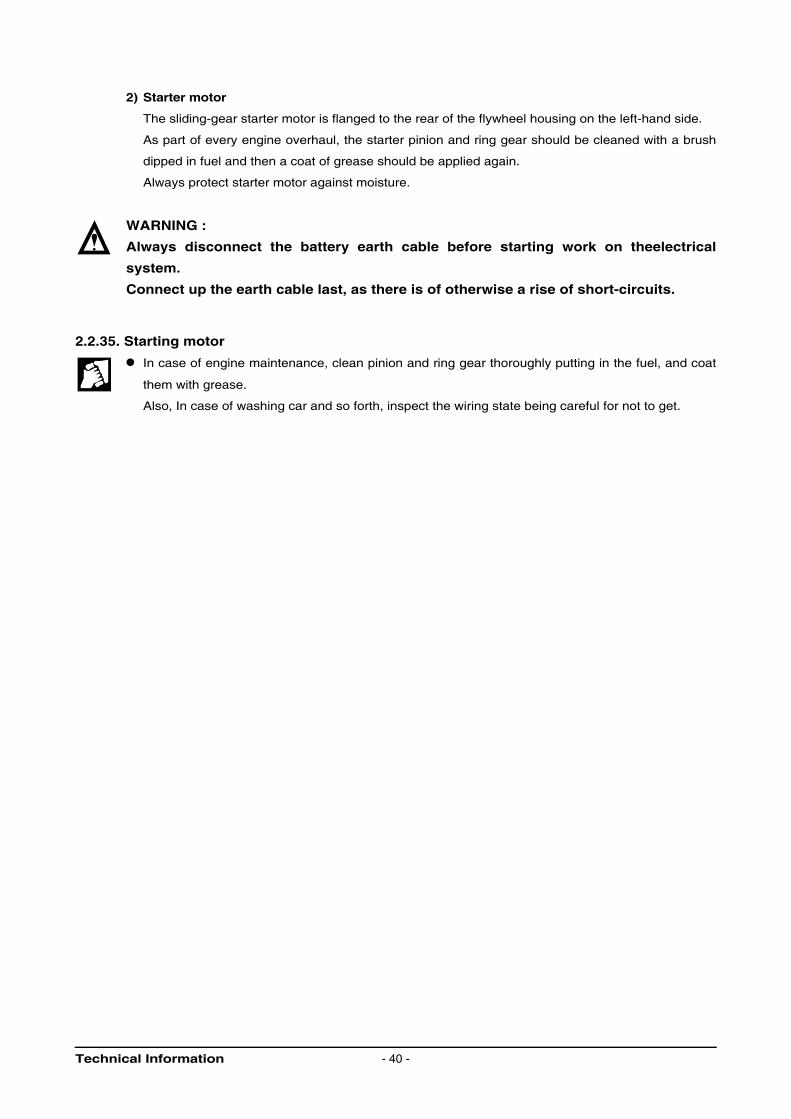
2.2.29. Battery
Inspect for any leakage of electrolytic solution owing to battery crack, and replace the battery in
case of poor condition.
Inspect for amount of electrolytic solution, and replenish if insufficient.
Measure the gravity of electrolytic solution, if less than specified value (1.12 ~ 1.28), replenish.
2.2.30. Air removal of fuel system
The suction room of fuel injection pump has the function of air removal continuously during the
operation through a relief valve.
Iin case that the suction room lacks fuel at all, for instance, in case of new installation of injection
pump, after loosening the air removing screws of cartridge filter respectively, remove the air by
operating the manual pump of fuel supply pump until bubble will disappear.
2.2.31. Fuel supply pump
Every time of engine oil replacement, the fuel strainer installed at the fuel supply pump should be
removed and cleaned.
2.2.32. Supercharger
The supercharger needs not arty special equipment
Every time of engine replacement, a leakage or clogging of oil pipes should be inspected. Air cleaner
should be maintained carefully for nut or foreign material not to get in. Periodic inspection should be
applied on the compressed air and exhaust gas pipes, For leaking air will bring the overheat engine, an
immediate repair must be done.
During the operation that is surrounded by the dust and oil mixed air, frequent cleaning must be done
on the impellers. Tear down the impeller casing (attention: be careful not to bend) and must clean with
non-acid solvent solution. If necessary, use plastic scraper If impeller is severely polluted, dip the
impeller into solution and may be better to clean it with stiff brush.
Then one thing to beware is to dip only impeller part and so do not support by impeller but bearing
housing.
1,1001,200
UPPER LEVELLOWER LEVEL
1,300
EFM1007I
Technical Information - 38 -
2.2.33. Air cleaner
Air cleaner is mounted on the engine to purify the air for combustion.
The intervals at which the air cleaner requires servicing depend on the specific operating conditions
encountered. Clogged air filters may cause black smoke and reduce power.
A check should be made from time to time to see that the fastening elements securing the air cleaner
to the intake manifold seal the connection tightly. Any ingress of unfiltered air is liable to cause a high
rate of cylinder and piston wear.
2.2.34. Electrical equipment
1) Alternator
The alternator is fitted with integral silicon rectifiers. A transistorized regulator mounted on the
alternator body interior limits the alternator voltage. The alternator should not be operated except
with the regulator and battery connected in circuit to avoid damage to the rectifier and regulator.
The alternator is maintenance-free, nevertheless, it must be protected against dust and, above all,
against moisture and water.
Operate the alternator according to
the instructions given in the chapter
“Commissioning and operation”.
EA8O3006
P-TAB : KET GP 890545TACHOMETER CHARGE INDICATORALDO SYSTEM FREQUENCY = M6 x 1.0 THREAD
BATTERY TERMINALRPM10
"L" Terminal"R" Terminal
CONNECTOR HOUSING KET MG 620042TERMINAL KET ST 740254
To Battery +
EA8O3007
Regulator
RL = 150~250 OHM
Technical Information- 39 -
2) Starter motor
The sliding-gear starter motor is flanged to the rear of the flywheel housing on the left-hand side.
As part of every engine overhaul, the starter pinion and ring gear should be cleaned with a brush
dipped in fuel and then a coat of grease should be applied again.
Always protect starter motor against moisture.
WARNING :
Always disconnect the battery earth cable before starting work on theelectrical
system.
Connect up the earth cable last, as there is of otherwise a rise of short-circuits.
2.2.35. Starting motor
In case of engine maintenance, clean pinion and ring gear thoroughly putting in the fuel, and coat
them with grease.
Also, In case of washing car and so forth, inspect the wiring state being careful for not to get.
Technical Information - 40 -
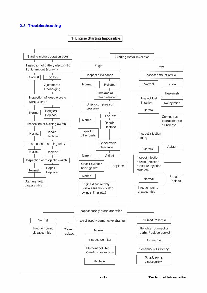
2.3. Troubleshooting
1. Engine Starting Impossible
Starting motor operation poor
Inspection of battery electorlyticIlquid amount & gravity
Normal Too low
Ajustment . Recharging
Inspection of starting switch
Normal Retigten . Replace
Inspection of starting relay
Inspection of magentic switch
Normal Replace
Normal Repair . Replace
Inspection of loose electric wring & short
NormalRepairReplace
Starting motordisassembly
Starting motor revolution
Engine
Inspect air cleaner
Normal Polluted
Replace orclean element
Check compression pressure
NormalToo low
Repair . Replace
Inspect ofother parts
Check valveclearance
Normal Adjust
Check cylinderhead gasket
Replace
Normal
Engine disassembly(valve assembly pistoncylinder liner etc.)
Fuel
Inspect amount of fuel
None
Replenish
Inspect fuelinjection No injection
Continuousoperation afterair removal
Inspect injectiontiming
Inspect injectionnozzle (injectionpressure injectionstate etc.)
Repair . Replace
Injection pumpdisassembly
Normal
Normal
Adjust
Normal
Normal
Inspect supply pump operation
Injection pump dasassembly
Clean . replace
Inspect fuel filter
Element pollutedOverflow valve poor
Replace
Air mixture in fuel
Retighten connectionparts. Replace gasket
Air removal
Continuous air mixing
Supply pump disassembly
Normal Inspect supply pump valve strainer
Normal
Technical Information- 41 -
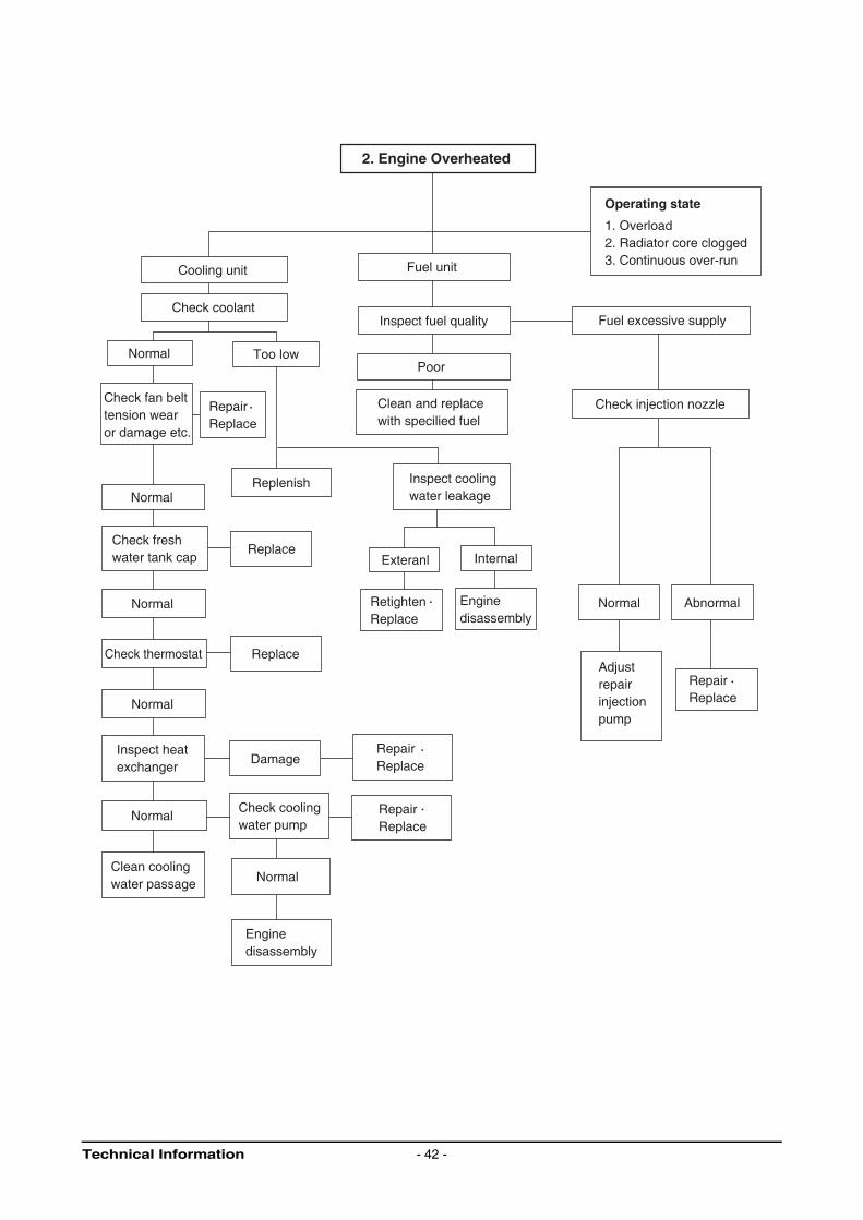
2. Engine Overheated
Cooling unit
Normal
Normal
Normal
Normal
Normal
Normal
Normal
Check fan belttension wearor damage etc.
Check freshwater tank cap
Clean coolingwater passage
Check coolant
Too low
Check thermostat
Inspect heatexchanger
RepairReplace
RepairReplace
RepairReplace
RepairReplace
Replenish
Replace
Replace
Damage
Check coolingwater pump
Enginedisassembly
Fuel unit
Inspect fuel quality
Poor
Clean and replacewith specilied fuel
Inspect coolingwater leakage
Exteranl Internal
Retighten Replace
Enginedisassembly
Operating state
1. Overload2. Radiator core clogged3. Continuous over-run
Fuel excessive supply
Check injection nozzle
Abnormal
Adjustrepairinjectionpump
Technical Information - 42 -
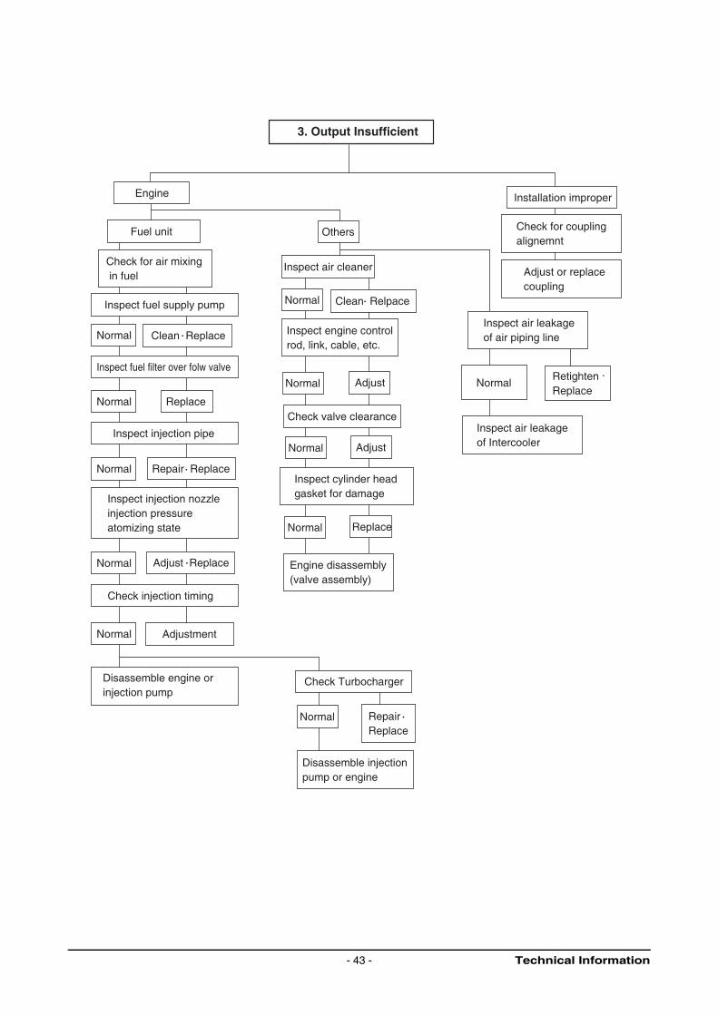
3. Output Insufficient
Engine
Fuel unit
Check for air mixing in fuel
Inspect fuel supply pump
Normal
Normal
Normal
Normal
Normal
Normal
Normal
Normal
Normal
Normal
Normal
Clean Replace
Inspect fuel filter over folw valve
Replace
Replace
Repair Replace
Inspect injection nozzleinjection pressureatomizing state
Adjust Replace
Check injection timing
Adjustment
Disassemble engine orinjection pump
Inspect injection pipe
Check Turbocharger
RepairReplace
Disassemble injectionpump or engine
Others
Inspect air cleaner
Clean Relpace
Inspect engine controlrod, link, cable, etc.
Adjust
Adjust
Inspect cylinder headgasket for damage
Engine disassembly(valve assembly)
Check valve clearance
Installation improper
Check for couplingalignemnt
Adjust or replacecoupling
Inspect air leakageof air piping line
Retighten . Replace
Inspect air leakageof Intercooler
Technical Information- 43 -
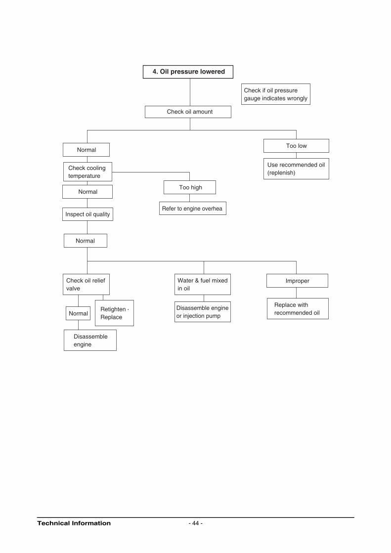
4. Oil pressure lowered
Check if oil pressuregauge indicates wrongly
Check oil amount
Normal
Normal
Normal
Normal
Check coolingtemperature
Inspect oil quality
Check oil reliefvalve
RetightenReplace
Disassembleengine
Too high
Refer to engine overhea
Water & fuel mixedin oil
Disassemble engineor injection pump
Improper
Replace withrecommended oil
Too low
Use recommended oil(replenish)
Technical Information - 44 -
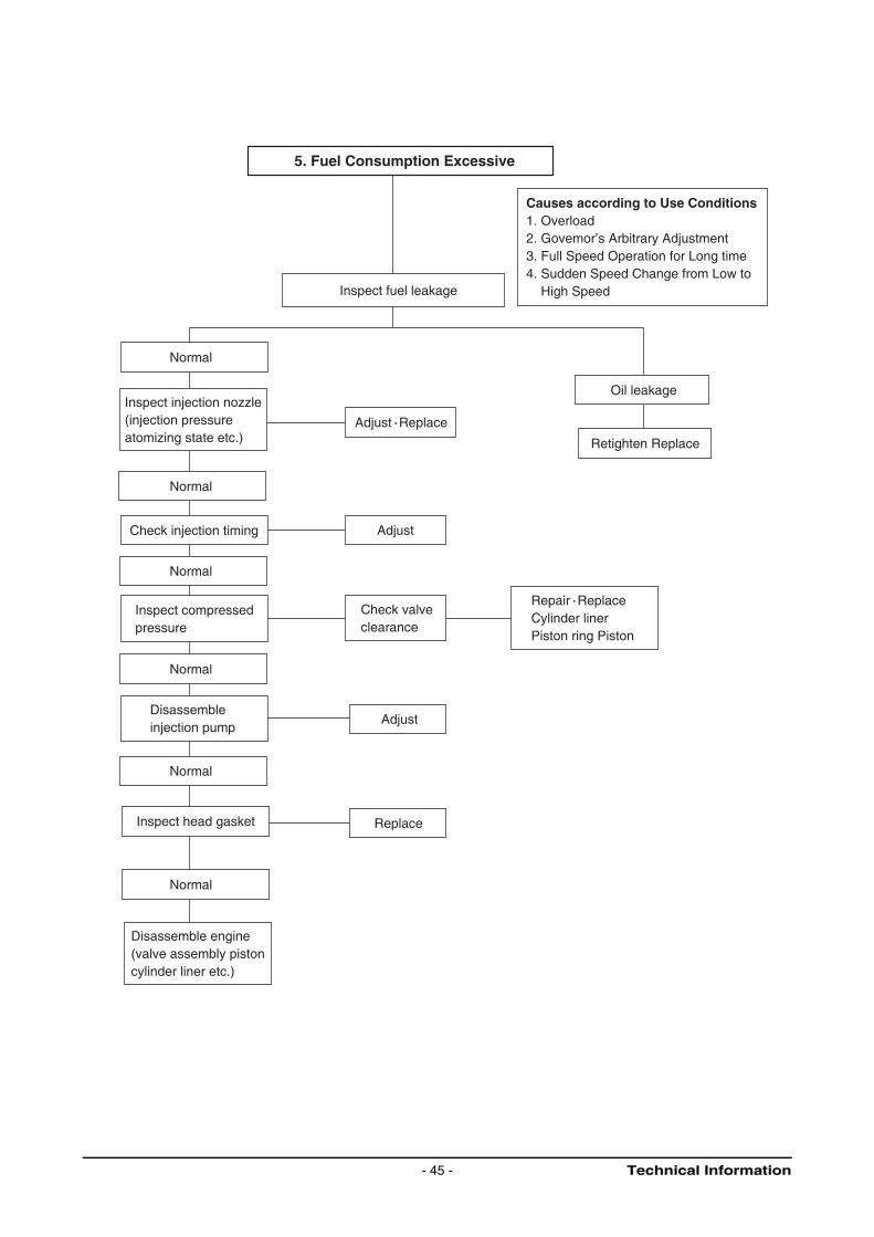
5. Fuel Consumption Excessive
Inspect fuel leakage
Normal
Normal
Normal
Normal
Normal
Normal
Inspect injection nozzle(injection pressureatomizing state etc.)
Check injection timing
Inspect compressedpressure
Disassembleinjection pump
Inspect head gasket
Disassemble engine(valve assembly pistoncylinder liner etc.)
Adjust Replace
Adjust
Adjust
Check valveclearance
Replace
Causes according to Use Conditions1. Overload2. Govemor’s Arbitrary Adjustment3. Full Speed Operation for Long time4. Sudden Speed Change from Low to High Speed
Oil leakage
Retighten Replace
Repair Replace Cylinder linerPiston ring Piston
Technical Information- 45 -
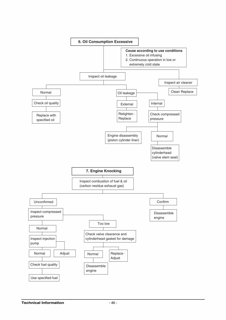
6. Oil Consumption Excessive
Cause according to use conditions1. Excessive oil infusing2. Continuous operation in low or extremely cold state
Inspect oil leakage
Normal
Normal
Normal Normal
Normal
Check oil quality
Replace withspecified oil
Oil leakage
External Internal
RetightenReplace
Check compressedpressure
Engine disassembly(piston cylinder liner)
Disassemblecylinderhead(valve stem seal)
Inspect air cleaner
Clean Replace
7. Engine Knocking
Inspect combustion of fuel & oil(carbon residue exhaust gas)
Unconfirmed
Inspect compressedpressure
Inspect injectionpump
Adjust
Check fuel quality
Use specified fuel
Too low
Check valve clearance andcylinderhead gasket for damage
ReplaceAdjust
Disassembleengine
Confirm
Disassembleengine
Technical Information - 46 -
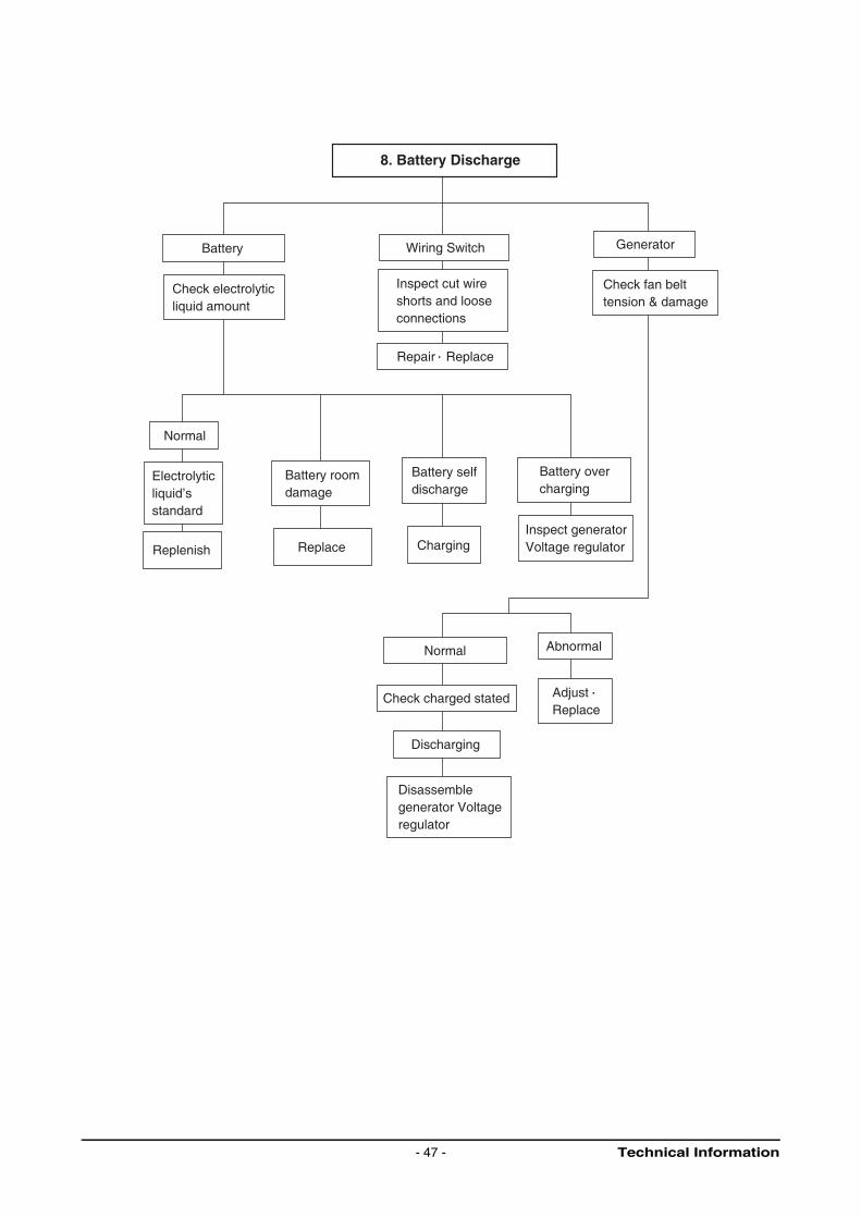
8. Battery Discharge
Battery
Check electrolyticliquid amount
Wiring Switch
Inspect cut wireshorts and looseconnections
Repair Replace
Generator
Check fan belttension & damage
Normal
Normal
Electrolyticliquid’sstandard
Replenish
Battery roomdamage
Replace
Battery selfdischarge
Charging
Battery over charging
Inspect generatorVoltage regulator
Check charged stated
Discharging
Disassemblegenerator Voltageregulator
Abnormal
AdjustReplace
Technical Information- 47 -
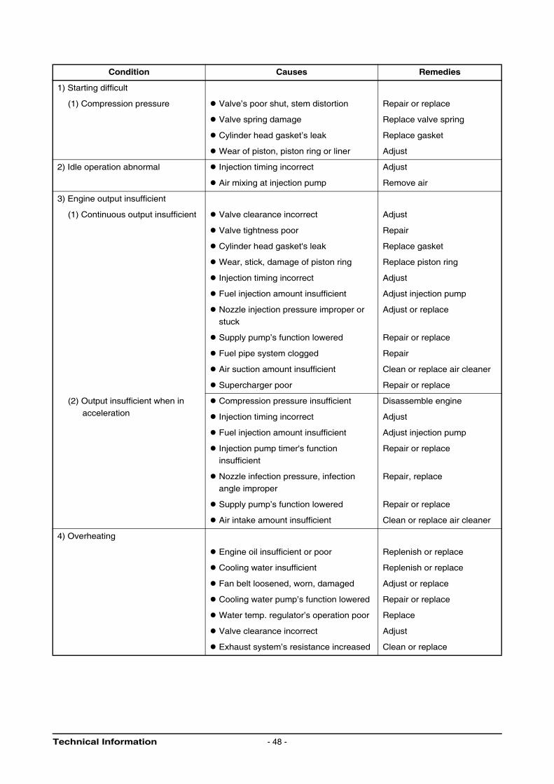
Condition Causes Remedies
1) Starting difficult
(1) Compression pressure Valve’s poor shut, stem distortion Repair or replace
Valve spring damage Replace valve spring
Cylinder head gasket’s leak Replace gasket
Wear of piston, piston ring or liner Adjust
2) Idle operation abnormal Injection timing incorrect Adjust
Air mixing at injection pump Remove air
3) Engine output insufficient
(1) Continuous output insufficient Valve clearance incorrect Adjust
Valve tightness poor Repair
Cylinder head gasket's leak Replace gasket
Wear, stick, damage of piston ring Replace piston ring
Injection timing incorrect Adjust
Fuel injection amount insufficient Adjust injection pump
Nozzle injection pressure improper or
stuck
Adjust or replace
Supply pump’s function lowered Repair or replace
Fuel pipe system clogged Repair
Air suction amount insufficient Clean or replace air cleaner
Supercharger poor Repair or replace
(2) Output insufficient when in
acceleration
Compression pressure insufficient Disassemble engine
Injection timing incorrect Adjust
Fuel injection amount insufficient Adjust injection pump
Injection pump timer's function
insufficient
Repair or replace
Nozzle infection pressure, infection
angle improper
Repair, replace
Supply pump’s function lowered Repair or replace
Air intake amount insufficient Clean or replace air cleaner
4) Overheating
Engine oil insufficient or poor Replenish or replace
Cooling water insufficient Replenish or replace
Fan belt loosened, worn, damaged Adjust or replace
Cooling water pump’s function lowered Repair or replace
Water temp. regulator’s operation poor Replace
Valve clearance incorrect Adjust
Exhaust system’s resistance increased Clean or replace
Technical Information - 48 -
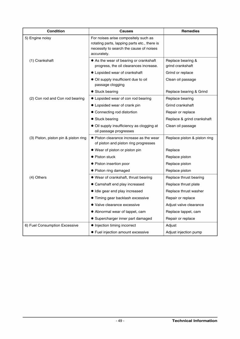
Condition Causes Remedies
5) Engine noisy For noises arise compositely such as rotating parts, lapping parts etc., there is
necessity to search the cause of noises
accurately.
(1) Crankshaft As the wear of bearing or crankshaft
progress, the oil clearances increase.
Replace bearing &
grind crankshaft
Lopsided wear of crankshaft Grind or replace
Oil supply insufficient due to oil
passage clogging
Clean oil passage
Stuck bearing Replace bearing & Grind
(2) Con rod and Con rod bearing Lopsided wear of con rod bearing Replace bearing
Lopsided wear of crank pin Grind crankshaft
Connecting rod distortion Repair or replace
Stuck bearing Replace & grind crankshaft
Oil supply insufficiency as clogging at
oil passage progresses
Clean oil passage
(3) Piston, piston pin & piston ring Piston clearance increase as the wear
of piston and piston ring progresses
Replace piston & piston ring
Wear of piston or piston pin Replace
Piston stuck Replace piston
Piston insertion poor Replace piston
Piston ring damaged Replace piston
(4) Others Wear of crankshaft, thrust bearing Replace thrust bearing
Camshaft end play increased Replace thrust plate
Idle gear end play increased Replace thrust washer
Timing gear backlash excessive Repair or replace
Valve clearance excessive Adjust valve clearance
Abnormal wear of tappet, cam Replace tappet, cam
Supercharger inner part damaged Repair or replace
6) Fuel Consumption Excessive Injection timing incorrect Adjust
Fuel injection amount excessive Adjust injection pump
Technical Information- 49 -
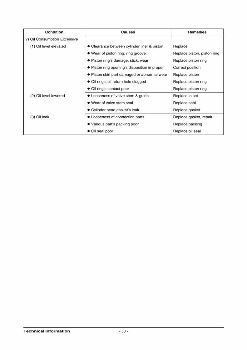
Condition Causes Remedies
7) Oil Consumption Excessive
(1) Oil level elevated Clearance between cylinder liner & piston Replace
Wear of piston ring, ring groove Replace piston, piston ring
Piston ring’s damage, stick, wear Replace piston ring
Piston ring opening’s disposition improper Correct position
Piston skirt part damaged or abnormal wear Replace piston
Oil ring’s oil return hole clogged Replace piston ring
Oil ring’s contact poor Replace piston ring
(2) Oil level lowered Looseness of valve stem & guide Replace in set
Wear of valve stem seal Replace seal
Cylinder head gasket’s leak Replace gasket
(3) Oil leak Looseness of connection parts Replace gasket, repair
Various part’s packing poor Replace packing
Oil seal poor Replace oil seal
Technical Information - 50 -
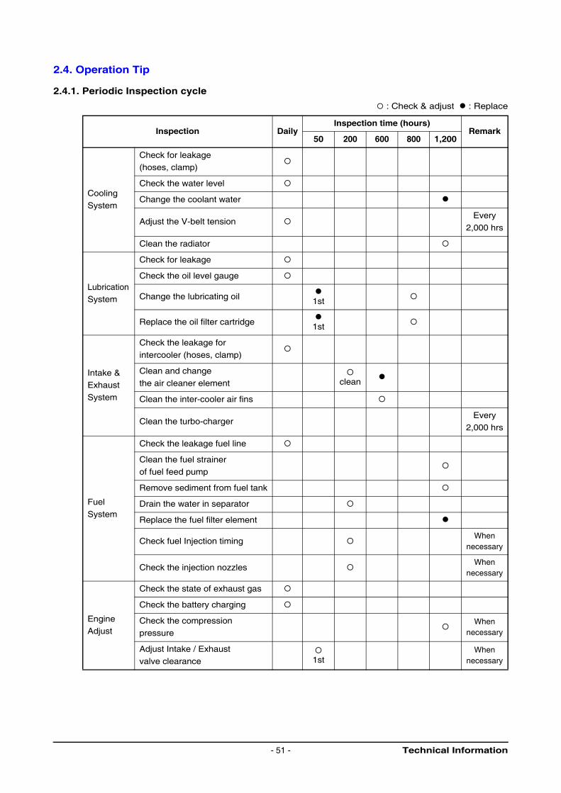
2.4. Operation Tip
2.4.1. Periodic Inspection cycle
: Check & adjust : Replace
Inspection DailyInspection time (hours)
Remark50 200 600 800 1,200
Cooling
System
Check for leakage
(hoses, clamp)
Check the water level
Change the coolant water
Adjust the V-belt tensionEvery
2,000 hrs
Clean the radiator
LubricationSystem
Check for leakage
Check the oil level gauge
Change the lubricating oil 1st
Replace the oil filter cartridge 1st
Intake & Exhaust
System
Check the leakage for
intercooler (hoses, clamp)
Clean and change
the air cleaner element
clean
Clean the inter-cooler air fins
Clean the turbo-chargerEvery
2,000 hrs
Fuel
System
Check the leakage fuel line
Clean the fuel strainer
of fuel feed pump
Remove sediment from fuel tank
Drain the water in separator
Replace the fuel filter element
Check fuel Injection timingWhen
necessary
Check the injection nozzlesWhen
necessary
Engine Adjust
Check the state of exhaust gas
Check the battery charging
Check the compression
pressureWhen
necessary
Adjust Intake / Exhaust
valve clearance 1stWhen
necessary
Technical Information- 51 -
3. Disassembly and Reassembly of Major Components
3.1. Engine Disassembly
Engine part’s disassembly procedures are as follows;
For the various tool storage before disassembly and parts storage after disassembly, the shelf for
parts is prepared.
At the time of disassembly and reassembly, do the work with the naked and clean hand, and also the
working place must be maintained clean.
The torn parts after disassembly must be kept not to collide each other.
In disassembling, torn parts should be laid in disassembled order.
3.1.1. Oil level gauge
Take out the oil level gauge
3.1.2. Engine oil
Remove an oil drain cock from the oil pan, and let engine oil discharge into the prepared vessel.
3.1.3. Cooling water
Remove the cooling water drain plug from the cylinder block and oil cooler, various pipes, etc. and let
the cooling water discharge into the prepared vessel.
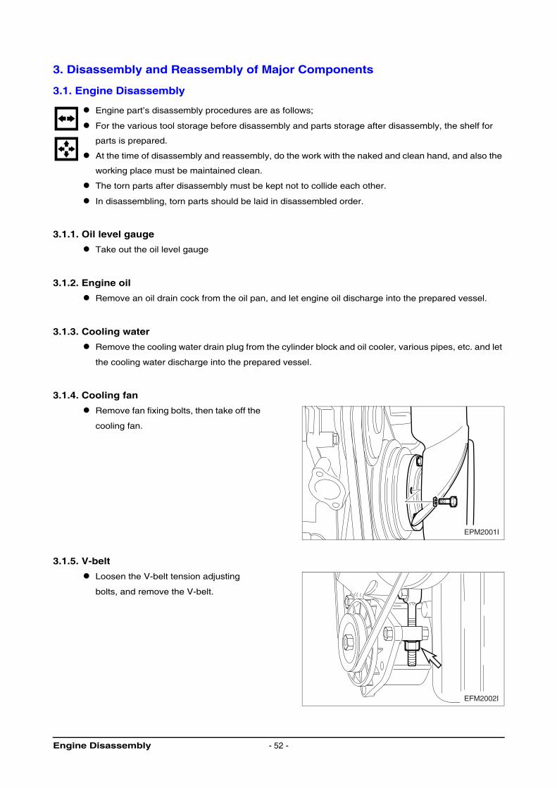
3.1.4. Cooling fan
Remove fan fixing bolts, then take off the
cooling fan.
3.1.5. V-belt
Loosen the V-belt tension adjusting
bolts, and remove the V-belt.
EPM2001I
EFM2002I
Engine Disassembly - 52 -
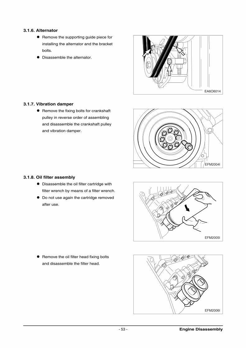
3.1.6. Alternator
Remove the supporting guide piece for
installing the alternator and the bracket
bolts.
Disassemble the alternator.
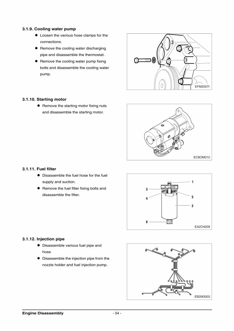
3.1.7. Vibration damper
Remove the fixing bolts for crankshaft
pulley in reverse order of assembling
and disassemble the crankshaft pulley
and vibration damper.
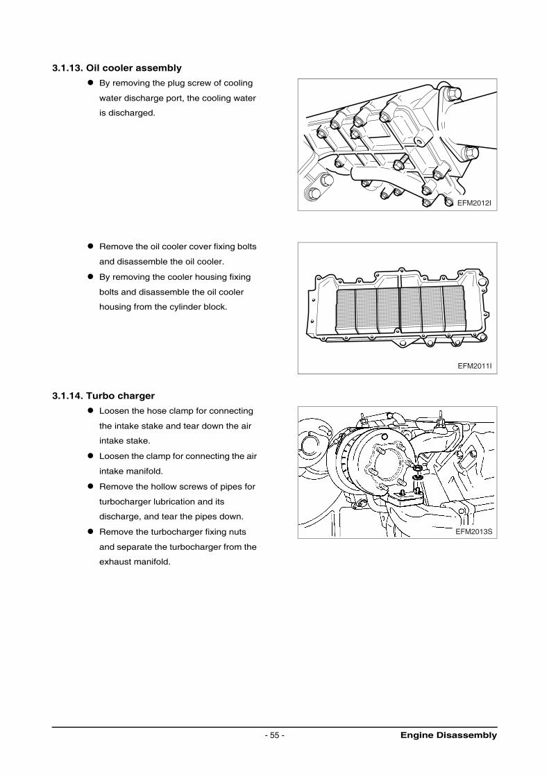
3.1.8. Oil filter assembly
Disassemble the oil filter cartridge with
filter wrench by means of a filter wrench.
Do not use again the cartridge removed
after use.
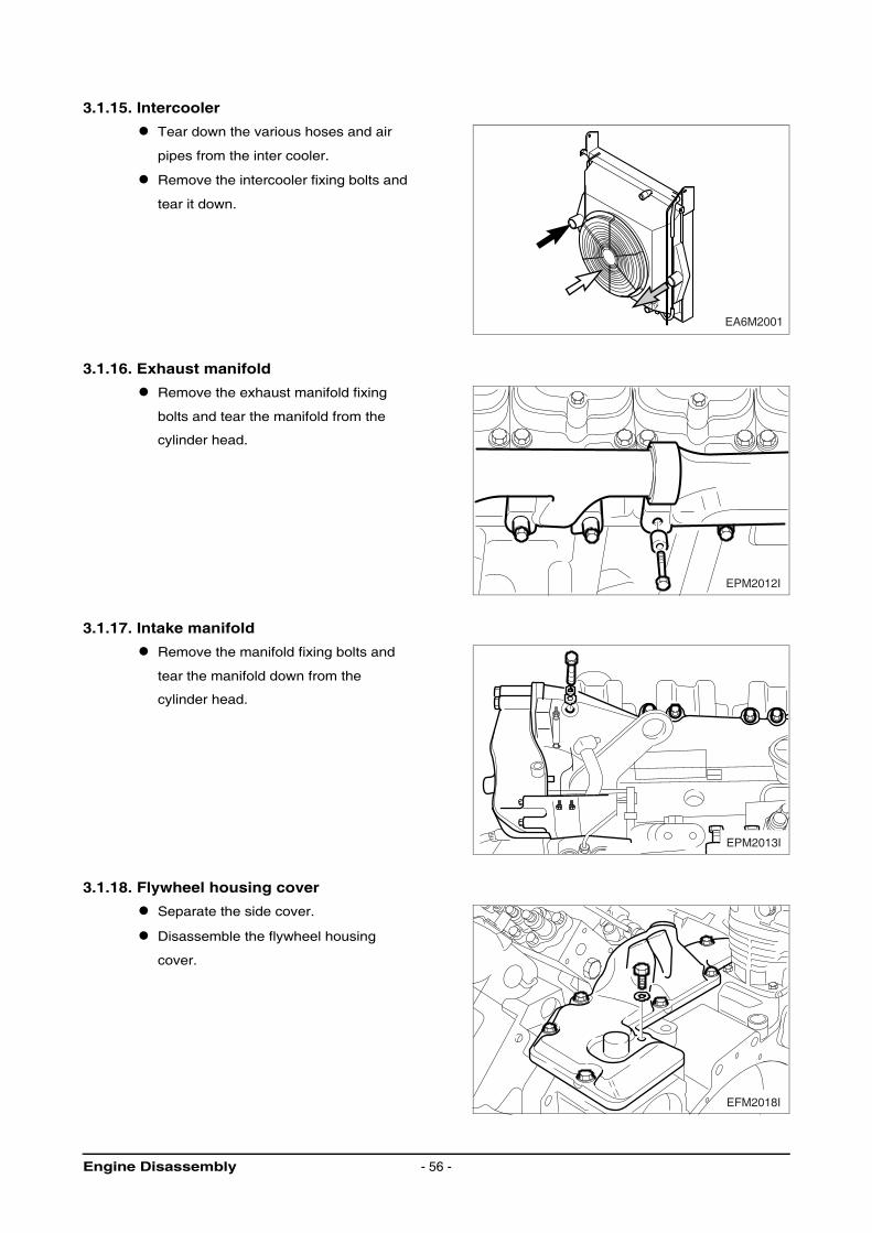
Remove the oil filter head fixing bolts
and disassemble the filter head.
EA6O6014
EFM2004I
EFM2005I
EFM2006I
Engine Disassembly- 53 -
3.1.9. Cooling water pump
Loosen the various hose clamps for the
connections.
Remove the cooling water discharging
pipe and disassemble the thermostat.
Remove the cooling water pump fixing
bolts and disassemble the cooling water
pump.
3.1.10. Starting motor
Remove the starting motor fixing nuts
and disassemble the starting motor.
3.1.11. Fuel filter
Disassemble the fuel hose for the fuel
supply and suction.
Remove the fuel filter fixing bolts and
disassemble the filter.
3.1.12. Injection pipe
Disassemble various fuel pipe and
hose.
Disassemble the injection pipe from the
nozzle holder and fuel injection pump.
EFM2007I
EC8OM010
1
5
2
3
4
6EA2O4009
EB2M3003
Engine Disassembly - 54 -
3.1.13. Oil cooler assembly
By removing the plug screw of cooling
water discharge port, the cooling water
is discharged.
Remove the oil cooler cover fixing bolts
and disassemble the oil cooler.
By removing the cooler housing fixing
bolts and disassemble the oil cooler
housing from the cylinder block.
3.1.14. Turbo charger
Loosen the hose clamp for connecting
the intake stake and tear down the air
intake stake.
Loosen the clamp for connecting the air
intake manifold.
Remove the hollow screws of pipes for
turbocharger lubrication and its
discharge, and tear the pipes down.
Remove the turbocharger fixing nuts
and separate the turbocharger from the
exhaust manifold.
EFM2012I
EFM2011I
EFM2013S
Engine Disassembly- 55 -
3.1.15. Intercooler
Tear down the various hoses and air
pipes from the inter cooler.
Remove the intercooler fixing bolts and
tear it down.
3.1.16. Exhaust manifold
Remove the exhaust manifold fixing
bolts and tear the manifold from the
cylinder head.
3.1.17. Intake manifold
Remove the manifold fixing bolts and
tear the manifold down from the
cylinder head.
3.1.18. Flywheel housing cover
Separate the side cover.
Disassemble the flywheel housing
cover.
EA6M2001
EPM2012I
EPM2013I
EFM2018I
Engine Disassembly - 56 -
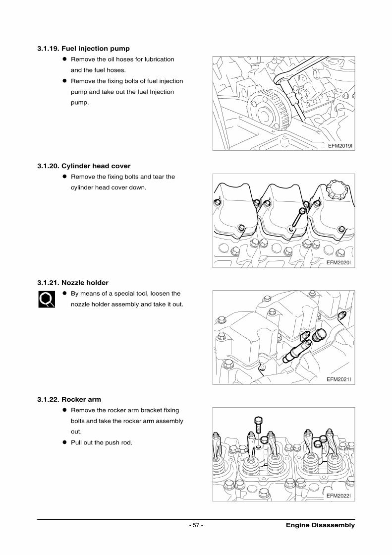
3.1.19. Fuel injection pump
Remove the oil hoses for lubrication
and the fuel hoses.
Remove the fixing bolts of fuel injection
pump and take out the fuel Injection
pump.
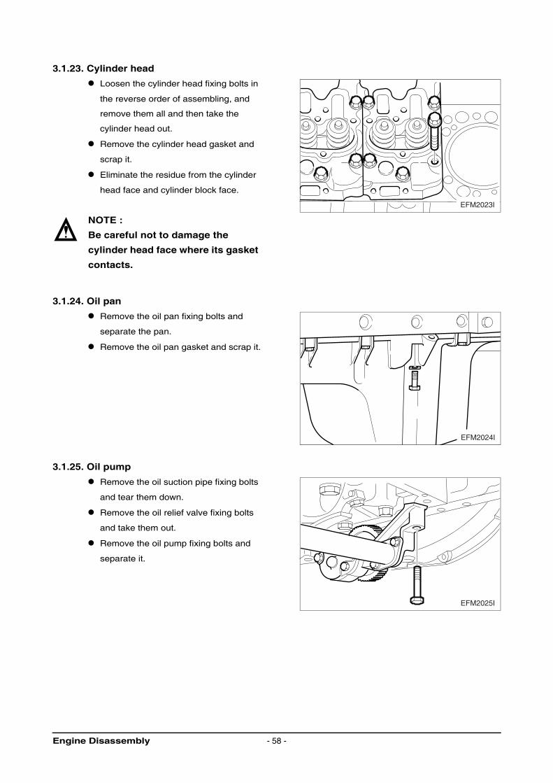
3.1.20. Cylinder head cover
Remove the fixing bolts and tear the
cylinder head cover down.
3.1.21. Nozzle holder
By means of a special tool, loosen the
nozzle holder assembly and take it out.
3.1.22. Rocker arm
Remove the rocker arm bracket fixing
bolts and take the rocker arm assembly
out.
Pull out the push rod.
EFM2019I
EFM2020I
EFM2021I
EFM2022I
Engine Disassembly- 57 -
3.1.23. Cylinder head
Loosen the cylinder head fixing bolts in
the reverse order of assembling, and
remove them all and then take the
cylinder head out.
Remove the cylinder head gasket and
scrap it.
Eliminate the residue from the cylinder
head face and cylinder block face.
NOTE :
Be careful not to damage the
cylinder head face where its gasket
contacts.
3.1.24. Oil pan
Remove the oil pan fixing bolts and
separate the pan.
Remove the oil pan gasket and scrap it.
3.1.25. Oil pump
Remove the oil suction pipe fixing bolts
and tear them down.
Remove the oil relief valve fixing bolts
and take them out.
Remove the oil pump fixing bolts and
separate it.
EFM2023I
EFM2024I
EFM2025I
Engine Disassembly - 58 -
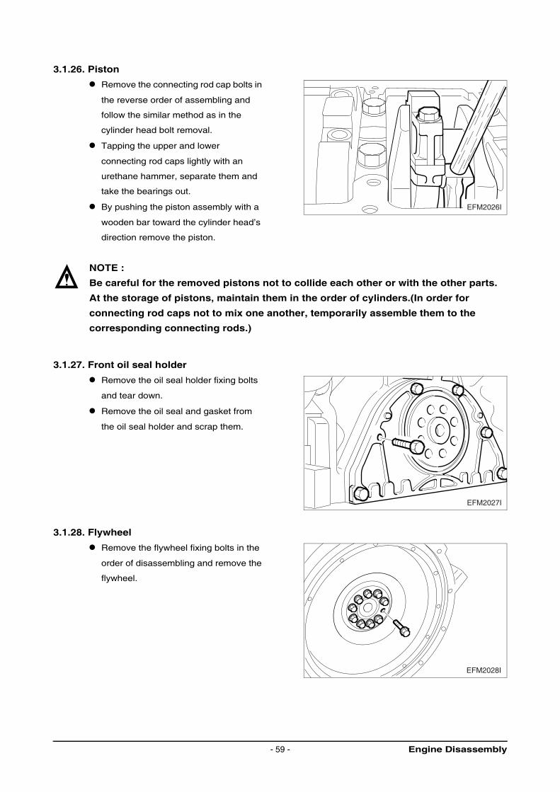
3.1.26. Piston
Remove the connecting rod cap bolts in
the reverse order of assembling and
follow the similar method as in the
cylinder head bolt removal.
Tapping the upper and lower
connecting rod caps lightly with an
urethane hammer, separate them and
take the bearings out.
By pushing the piston assembly with a
wooden bar toward the cylinder head’s
direction remove the piston.
NOTE :
Be careful for the removed pistons not to collide each other or with the other parts.
At the storage of pistons, maintain them in the order of cylinders.(In order for
connecting rod caps not to mix one another, temporarily assemble them to the
corresponding connecting rods.)
3.1.27. Front oil seal holder
Remove the oil seal holder fixing bolts
and tear down.
Remove the oil seal and gasket from
the oil seal holder and scrap them.
3.1.28. Flywheel
Remove the flywheel fixing bolts in the
order of disassembling and remove the
flywheel.
EFM2026I
EFM2027I
EFM2028I
Engine Disassembly- 59 -
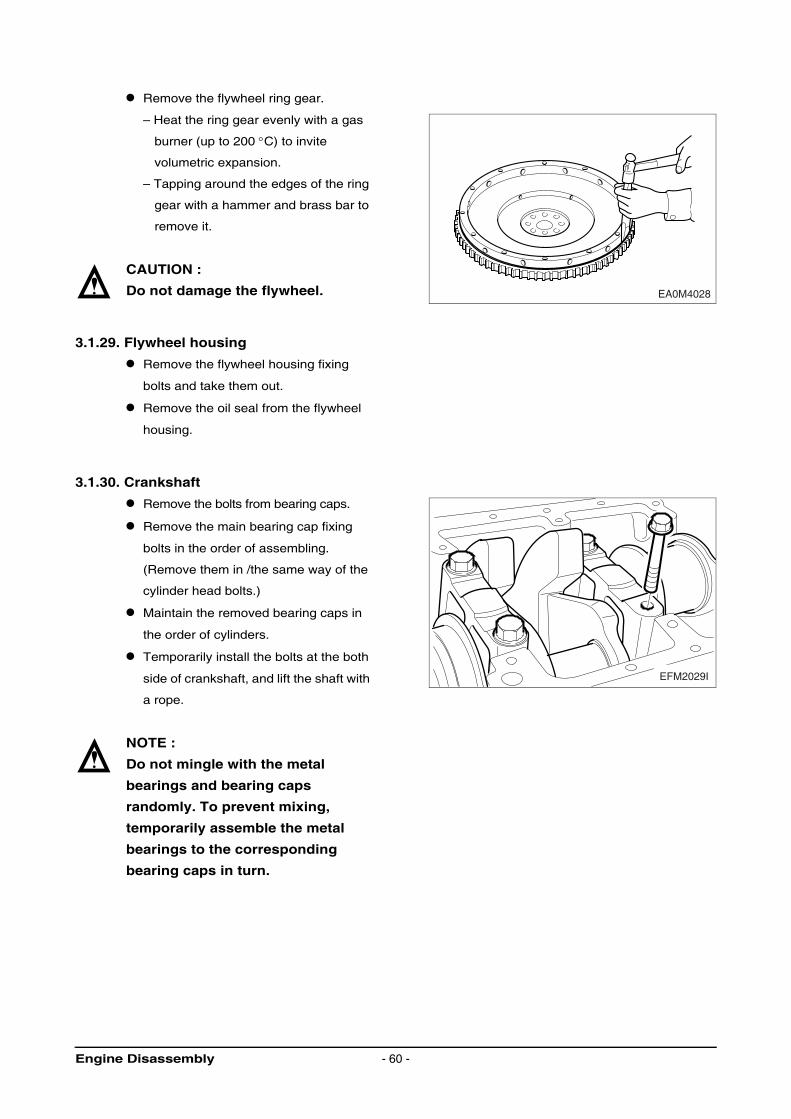
Remove the flywheel ring gear.
– Heat the ring gear evenly with a gas
burner (up to 200 °C) to invite
volumetric expansion.
– Tapping around the edges of the ring
gear with a hammer and brass bar to
remove it.
CAUTION :
Do not damage the flywheel.
3.1.29. Flywheel housing
Remove the flywheel housing fixing
bolts and take them out.
Remove the oil seal from the flywheel
housing.
3.1.30. Crankshaft
Remove the bolts from bearing caps.
Remove the main bearing cap fixing
bolts in the order of assembling.
(Remove them in /the same way of the
cylinder head bolts.)
Maintain the removed bearing caps in
the order of cylinders.
Temporarily install the bolts at the both
side of crankshaft, and lift the shaft with
a rope.
NOTE :
Do not mingle with the metal
bearings and bearing caps
randomly. To prevent mixing,
temporarily assemble the metal
bearings to the corresponding
bearing caps in turn.
EA0M4028
EFM2029I
Engine Disassembly - 60 -
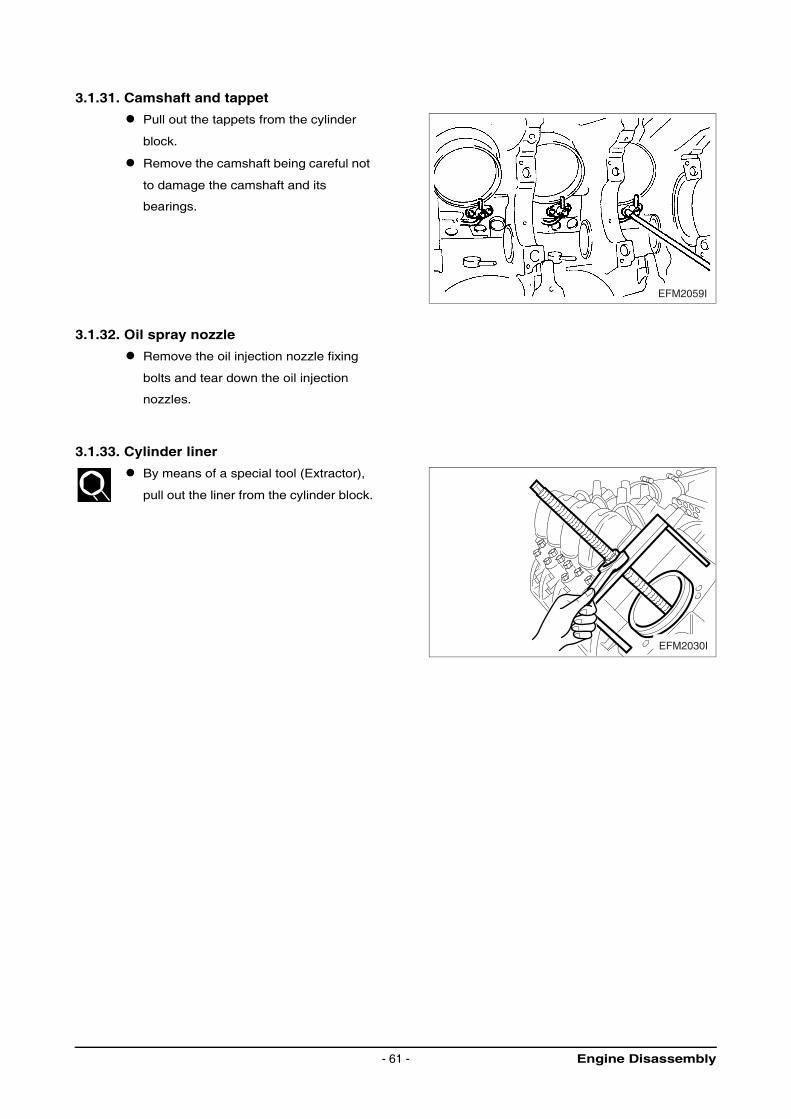
3.1.31. Camshaft and tappet
Pull out the tappets from the cylinder
block.
Remove the camshaft being careful not
to damage the camshaft and its
bearings.
3.1.32. Oil spray nozzle
Remove the oil injection nozzle fixing
bolts and tear down the oil injection
nozzles.
3.1.33. Cylinder liner
By means of a special tool (Extractor),
pull out the liner from the cylinder block.
EFM2059I
EFM2030I
Engine Disassembly- 61 -
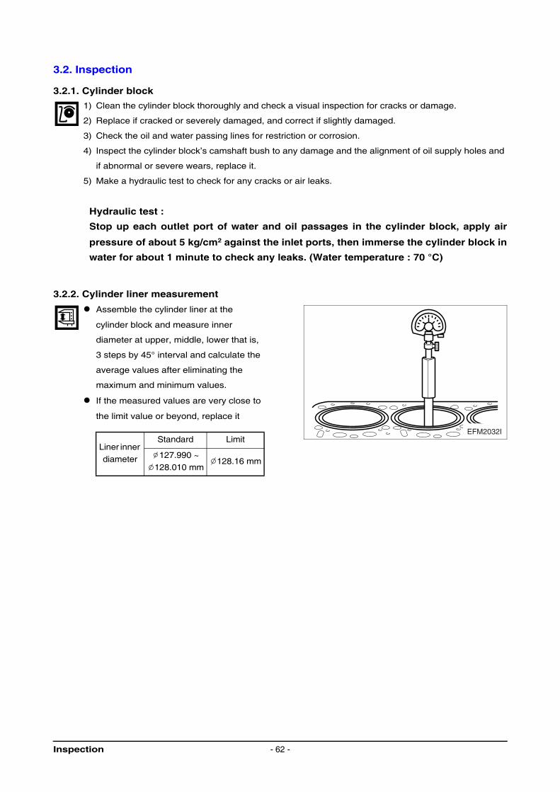
3.2. Inspection
3.2.1. Cylinder block
1) Clean the cylinder block thoroughly and check a visual inspection for cracks or damage.
2) Replace if cracked or severely damaged, and correct if slightly damaged.
3) Check the oil and water passing lines for restriction or corrosion.
4) Inspect the cylinder block’s camshaft bush to any damage and the alignment of oil supply holes and
if abnormal or severe wears, replace it.
5) Make a hydraulic test to check for any cracks or air leaks.
Hydraulic test :
Stop up each outlet port of water and oil passages in the cylinder block, apply air
pressure of about 5 kg/cm2 against the inlet ports, then immerse the cylinder block in
water for about 1 minute to check any leaks. (Water temperature : 70 °C)
3.2.2. Cylinder liner measurement
Assemble the cylinder liner at the
cylinder block and measure inner
diameter at upper, middle, lower that is,
3 steps by 45° interval and calculate the
average values after eliminating the
maximum and minimum values.
If the measured values are very close to
the limit value or beyond, replace it
Liner inner diameter
Standard Limit
127.990 ~ 128.010 mm
128.16 mm
EFM2032I
Inspection - 62 -
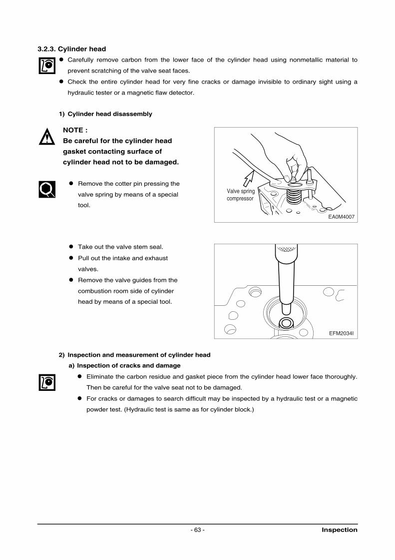
3.2.3. Cylinder head
Carefully remove carbon from the lower face of the cylinder head using nonmetallic material to
prevent scratching of the valve seat faces.
Check the entire cylinder head for very fine cracks or damage invisible to ordinary sight using a
hydraulic tester or a magnetic flaw detector.
1) Cylinder head disassembly
NOTE :
Be careful for the cylinder head
gasket contacting surface of
cylinder head not to be damaged.
Remove the cotter pin pressing the
valve spring by means of a special
tool.
Take out the valve stem seal.
Pull out the intake and exhaust
valves.
Remove the valve guides from the
combustion room side of cylinder
head by means of a special tool.
2) Inspection and measurement of cylinder head
a) Inspection of cracks and damage
Eliminate the carbon residue and gasket piece from the cylinder head lower face thoroughly.
Then be careful for the valve seat not to be damaged.
For cracks or damages to search difficult may be inspected by a hydraulic test or a magnetic
powder test. (Hydraulic test is same as for cylinder block.)
Valve springcompressor
EA0M4007
EFM2034I
Inspection- 63 -
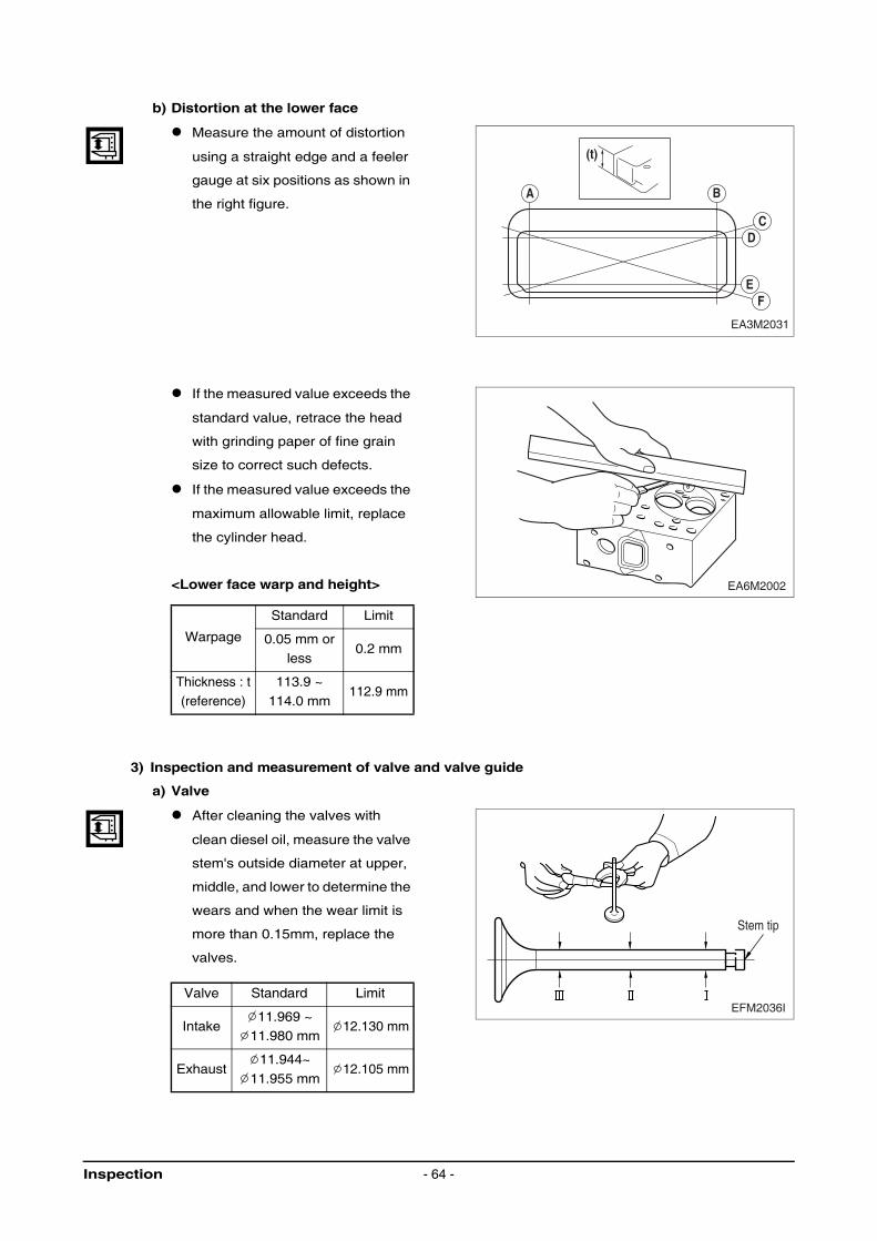
b) Distortion at the lower face
Measure the amount of distortion
using a straight edge and a feeler
gauge at six positions as shown in
the right figure.
If the measured value exceeds the
standard value, retrace the head
with grinding paper of fine grain
size to correct such defects.
If the measured value exceeds the
maximum allowable limit, replace
the cylinder head.
<Lower face warp and height>
3) Inspection and measurement of valve and valve guide
a) Valve
After cleaning the valves with
clean diesel oil, measure the valve
stem's outside diameter at upper,
middle, and lower to determine the
wears and when the wear limit is
more than 0.15mm, replace the
valves.
Warpage
Standard Limit
0.05 mm or
less0.2 mm
Thickness : t
(reference)
113.9 ~
114.0 mm112.9 mm
Valve Standard Limit
Intake11.969 ~
11.980 mm12.130 mm
Exhaust11.944~
11.955 mm12.105 mm
(t)
A B
CD
E
EA3M2031
F
EA6M2002
EFM2036I
Stem tip
Inspection - 64 -
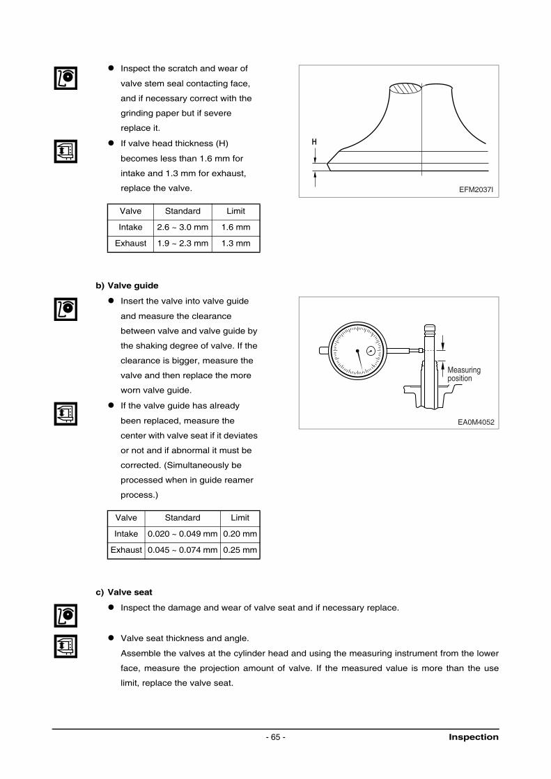
Inspect the scratch and wear of
valve stem seal contacting face,
and if necessary correct with the
grinding paper but if severe
replace it.
If valve head thickness (H)
becomes less than 1.6 mm for
intake and 1.3 mm for exhaust,
replace the valve.
b) Valve guide
Insert the valve into valve guide
and measure the clearance
between valve and valve guide by
the shaking degree of valve. If the
clearance is bigger, measure the
valve and then replace the more
worn valve guide.
If the valve guide has already
been replaced, measure the
center with valve seat if it deviates
or not and if abnormal it must be
corrected. (Simultaneously be
processed when in guide reamer
process.)
c) Valve seat
Inspect the damage and wear of valve seat and if necessary replace.
Valve seat thickness and angle.
Assemble the valves at the cylinder head and using the measuring instrument from the lower
face, measure the projection amount of valve. If the measured value is more than the use
limit, replace the valve seat.
Valve Standard Limit
Intake 2.6 ~ 3.0 mm 1.6 mm
Exhaust 1.9 ~ 2.3 mm 1.3 mm
Valve Standard Limit
Intake 0.020 ~ 0.049 mm 0.20 mm
Exhaust 0.045 ~ 0.074 mm 0.25 mm
EFM2037I
H
Measuringposition
EA0M4052
Inspection- 65 -
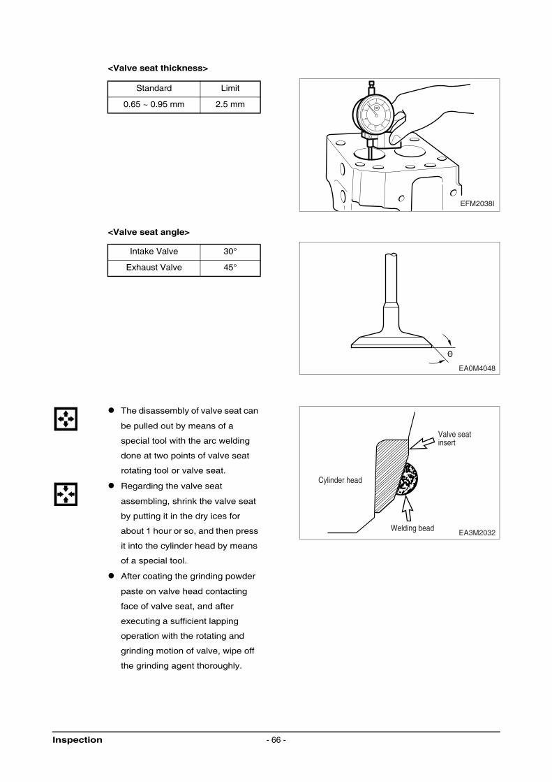
<Valve seat thickness>
<Valve seat angle>
The disassembly of valve seat can
be pulled out by means of a
special tool with the arc welding
done at two points of valve seat
rotating tool or valve seat.
Regarding the valve seat
assembling, shrink the valve seat
by putting it in the dry ices for
about 1 hour or so, and then press
it into the cylinder head by means
of a special tool.
After coating the grinding powder
paste on valve head contacting
face of valve seat, and after
executing a sufficient lapping
operation with the rotating and
grinding motion of valve, wipe off
the grinding agent thoroughly.
Standard Limit
0.65 ~ 0.95 mm 2.5 mm
Intake Valve 30°
Exhaust Valve 45°
1020
30
40
5060
70
80
90
0
EFM2038I
O
EA0M4048
EA3M2032
Valve seatinsert
Welding bead
Cylinder head
Inspection - 66 -

d) Valve spring
Inspect the outlook of valve spring
and if necessary replace it.
By means of spring tester,
measure the tension and free
length.
Measure the perpendicularity of
valve spring.
In case that the measured value
exceeds the limit value, replace it.
<Perpendicularity regular>
e) Assembling cylinder head
Clean the cylinder head thoroughly.
Coat the valve stems and valve guides with engine oil and assemble the valves.
Replace the valve stem seals with new ones and insert the stem seals to the valve guides of
cylinder head with a special tool. (Be careful for the valve stem seals not to be damaged)
Install the valve spring washer to valve guide.
After putting on the inside, outside spring, install the valve spring seat on them.
NOTE :
Install the valve spring seat with “TOP” (painted in yellow) side up.
Pressing the spring down with a
special tool, assemble by inserting
the valve cotter.
After the valve is assembled,
inspect the valve tapping it lightly
with an urethane hammer if
accurate assembling was done.
Inside Spring
Free length 65.5 mm
When given a regular load
(15 ~ 17 kg)46.3 mm
Outside Spring
Free length 64 mm
When given a regular load
(37 ~ 41 kg)46.3 mm
EFM2039I
1.0 mm or less
Free
leng
th
EFM2040I
Inspection- 67 -
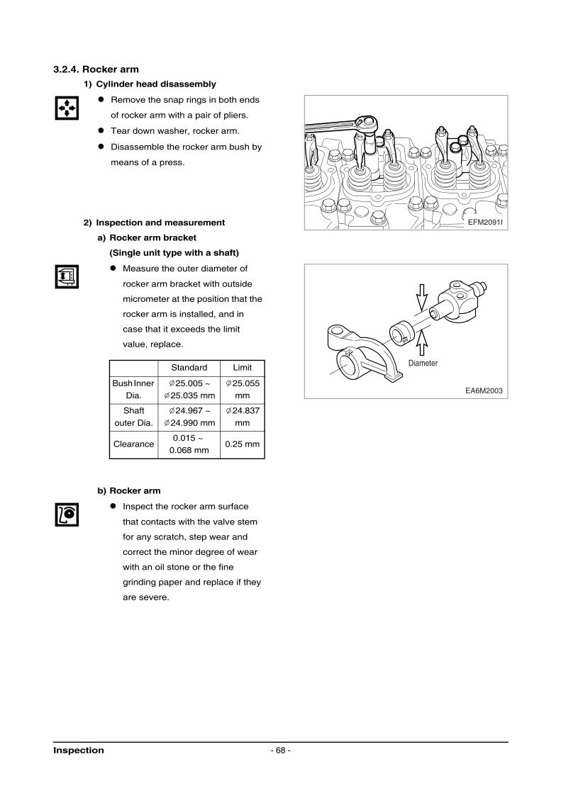
3.2.4. Rocker arm
1) Cylinder head disassembly
Remove the snap rings in both ends
of rocker arm with a pair of pliers.
Tear down washer, rocker arm.
Disassemble the rocker arm bush by
means of a press.
2) Inspection and measurement
a) Rocker arm bracket
(Single unit type with a shaft)
Measure the outer diameter of
rocker arm bracket with outside
micrometer at the position that the
rocker arm is installed, and in
case that it exceeds the limit
value, replace.
b) Rocker arm
Inspect the rocker arm surface
that contacts with the valve stem
for any scratch, step wear and
correct the minor degree of wear
with an oil stone or the fine
grinding paper and replace if they
are severe.
Standard Limit
Bush Inner Dia.
25.005 ~ 25.035 mm
25.055 mm
Shaft
outer Dia.
24.967 ~
24.990 mm
24.837
mm
Clearance0.015 ~
0.068 mm0.25 mm
EFM2091I
EA6M2003
Diameter
Inspection - 68 -
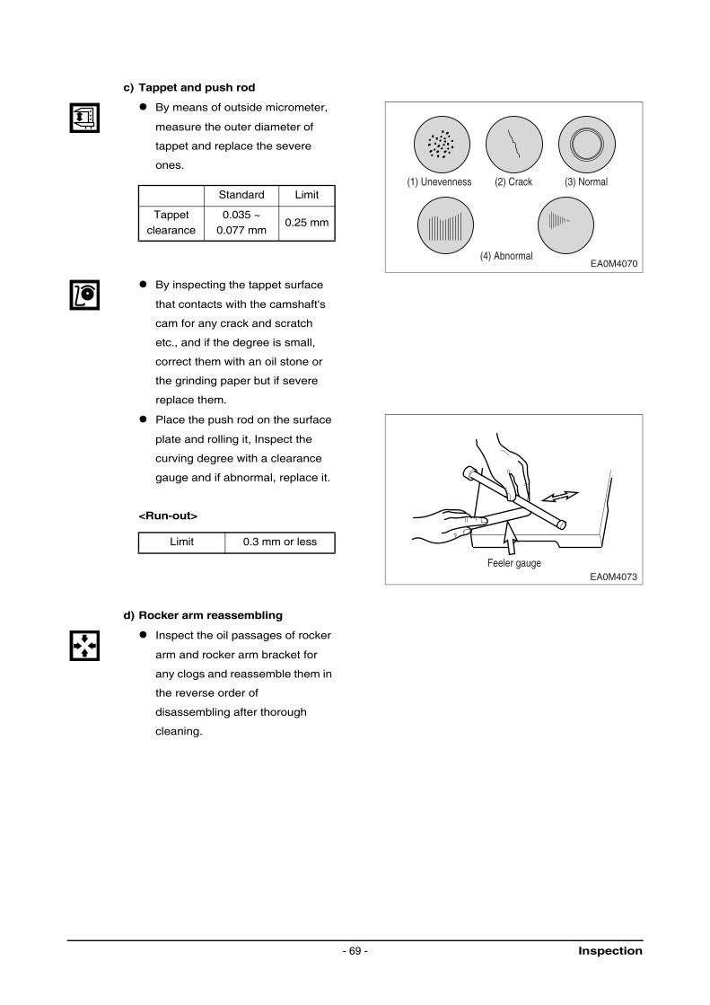
c) Tappet and push rod
By means of outside micrometer,
measure the outer diameter of
tappet and replace the severe
ones.
By inspecting the tappet surface
that contacts with the camshaft's
cam for any crack and scratch
etc., and if the degree is small,
correct them with an oil stone or
the grinding paper but if severe
replace them.
Place the push rod on the surface
plate and rolling it, Inspect the
curving degree with a clearance
gauge and if abnormal, replace it.
<Run-out>
d) Rocker arm reassembling
Inspect the oil passages of rocker
arm and rocker arm bracket for
any clogs and reassemble them in
the reverse order of
disassembling after thorough
cleaning.
Standard Limit
Tappet clearance
0.035 ~ 0.077 mm
0.25 mm
Limit 0.3 mm or less
EA0M4070
(1) Unevenness
(4) Abnormal
(2) Crack (3) Normal
EA0M4073Feeler gauge
Inspection- 69 -
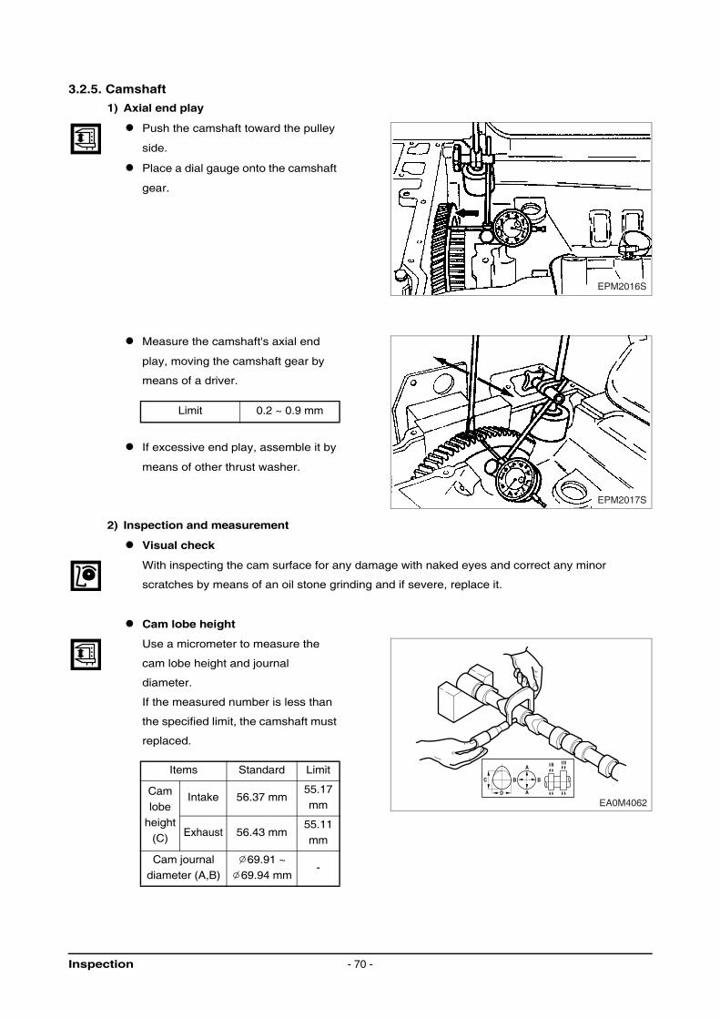
3.2.5. Camshaft
1) Axial end play
Push the camshaft toward the pulley
side.
Place a dial gauge onto the camshaft
gear.
Measure the camshaft's axial end
play, moving the camshaft gear by
means of a driver.
If excessive end play, assemble it by
means of other thrust washer.
2) Inspection and measurement
Visual check
With inspecting the cam surface for any damage with naked eyes and correct any minor
scratches by means of an oil stone grinding and if severe, replace it.
Cam lobe height
Use a micrometer to measure the
cam lobe height and journal
diameter.
If the measured number is less than
the specified limit, the camshaft must
replaced.
Limit 0.2 ~ 0.9 mm
Items Standard Limit
Cam
lobe height
(C)
Intake 56.37 mm55.17
mm
Exhaust 56.43 mm55.11
mm
Cam journal diameter (A,B)
69.91 ~ 69.94 mm
-
EPM2016S
EPM2017S
C
A
A
B B
D
I II I II
EA0M4062
Inspection - 70 -
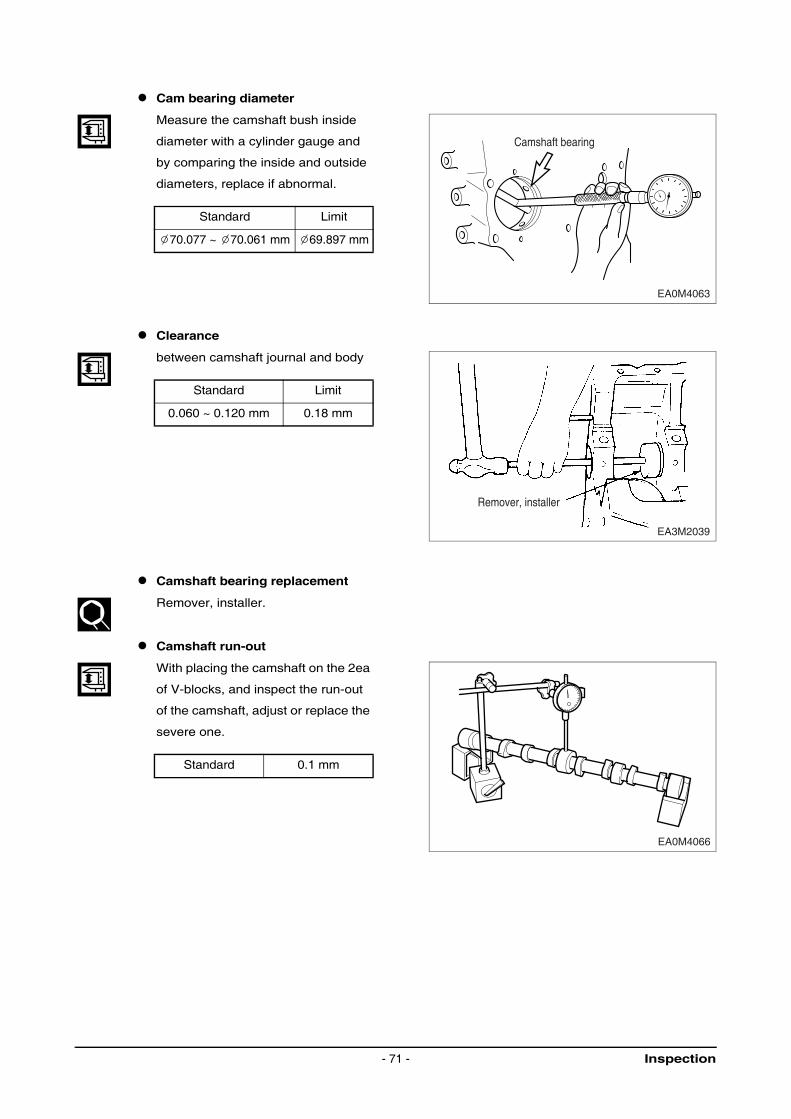
Cam bearing diameter
Measure the camshaft bush inside
diameter with a cylinder gauge and
by comparing the inside and outside
diameters, replace if abnormal.
Clearance
between camshaft journal and body
Camshaft bearing replacement
Remover, installer.
Camshaft run-out
With placing the camshaft on the 2ea
of V-blocks, and inspect the run-out
of the camshaft, adjust or replace the
severe one.
Standard Limit
70.077 ~ 70.061 mm 69.897 mm
Standard Limit
0.060 ~ 0.120 mm 0.18 mm
Standard 0.1 mm
EA0M4063
Camshaft bearing
Remover, installer
EA3M2039
EA0M4066
Inspection- 71 -
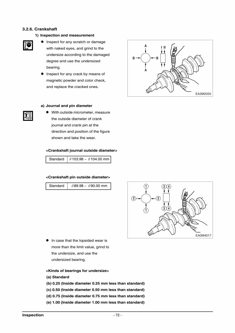
3.2.6. Crankshaft
1) Inspection and measurement
Inspect for any scratch or damage
with naked eyes, and grind to the
undersize according to the damaged
degree and use the undersized
bearing.
Inspect for any crack by means of
magnetic powder and color check,
and replace the cracked ones.
a) Journal and pin diameter
With outside micrometer, measure
the outside diameter of crank
journal and crank pin at the
direction and position of the figure
shown and take the wear.
<Crankshaft journal outside diameter>
<Crankshaft pin outside diameter>
In case that the lopsided wear is
more than the limit value, grind to
the undersize, and use the
undersized bearing.
<Kinds of bearings for undersize>
(a) Standard
(b) 0.25 (Inside diameter 0.25 mm less than standard)
(c) 0.50 (Inside diameter 0.50 mm less than standard)
(d) 0.75 (Inside diameter 0.75 mm less than standard)
(e) 1.00 (Inside diameter 1.00 mm less than standard)
Standard 103.98 ~ 104.00 mm
Standard 89.98 ~ 90.00 mm
A
A
B B
EA3M2050
I II
1
1
2
EA0M4017
2
3 4
3 4
Inspection - 72 -

There are 4 kinds as above, and the
crankshaft also can be used by
regrinding as above.
<“R part” standard value>
① Crank pin 'R' : 4.0
② Crank journal 'R' : 4.0
NOTE :
In case of crankshaft regrinding, the “R part” at the end of bearing must accurately
be ground without fail and should avoid any processed jaw or coarse surface
b) Run out of crankshaft
Place the crankshaft on the V-
block.
Place the dial gauge on the
surface plate and measure the run
out of crankshaft rotating the
crankshaft
2) Inspection on crankshaft bearing and connecting rod bearing Inspection
Inspect the crankshaft bearing and connecting rod bearing for any damages such as lopsided
wear, scratch etc. and if abnormal, replace it.
Inspect the oil clearance between the crankshaft and bearing.
a) How to utilize the cylinder gauge
Assemble the main bearing at the
cylinder block and after tightening
the bearing cap at the specified
torque, measure the inside
diameter.
Standard Limit
0.06 mm 0.4 mm
Journal bearing
nominal diameter
103.98 ~
104.00 mm
Bearing capBolt torque
Initial 30 kg⋅m + angle 90°
" R "
" R "
" R " " R " " R "
EFM2048I
0-0.5
0-0.5
EA0M4023
EA0M4019
Inspection- 73 -
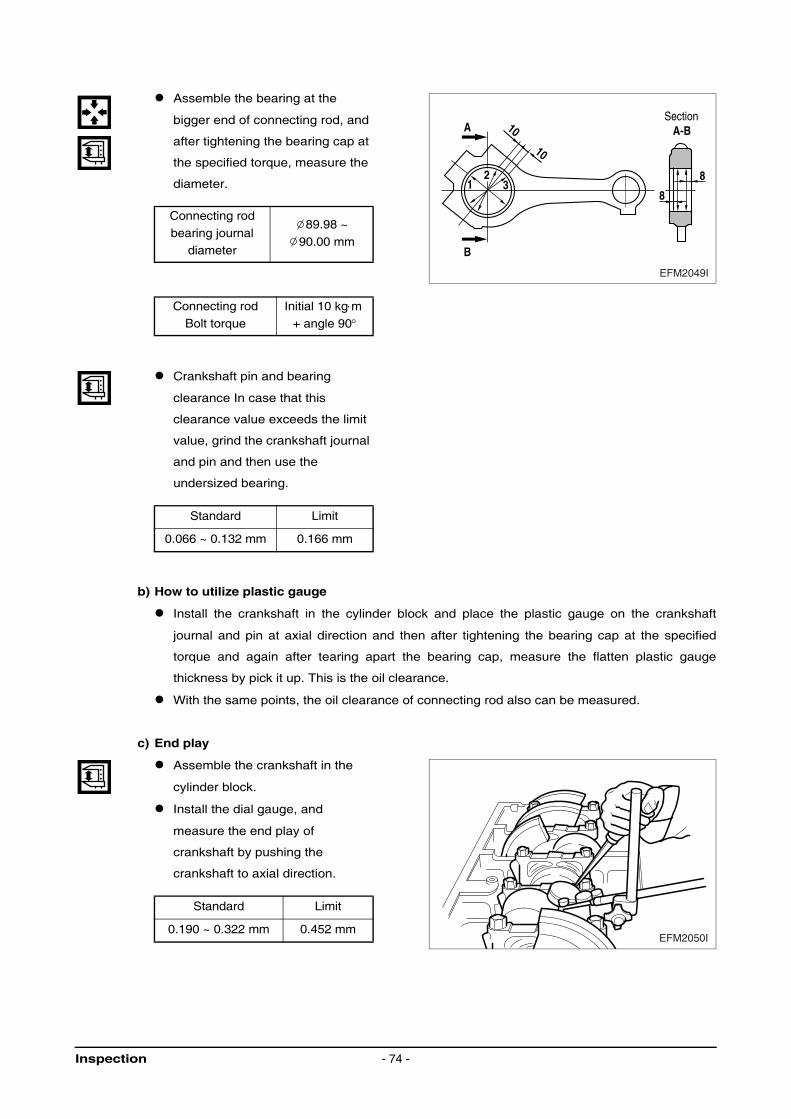
Assemble the bearing at the
bigger end of connecting rod, and
after tightening the bearing cap at
the specified torque, measure the
diameter.
Crankshaft pin and bearing
clearance In case that this
clearance value exceeds the limit
value, grind the crankshaft journal
and pin and then use the
undersized bearing.
b) How to utilize plastic gauge
Install the crankshaft in the cylinder block and place the plastic gauge on the crankshaft
journal and pin at axial direction and then after tightening the bearing cap at the specified
torque and again after tearing apart the bearing cap, measure the flatten plastic gauge
thickness by pick it up. This is the oil clearance.
With the same points, the oil clearance of connecting rod also can be measured.
c) End play
Assemble the crankshaft in the
cylinder block.
Install the dial gauge, and
measure the end play of
crankshaft by pushing the
crankshaft to axial direction.
Connecting rod
bearing journal diameter
89.98 ~
90.00 mm
Connecting rod
Bolt torque
Initial 10 kg⋅m
+ angle 90°
Standard Limit
0.066 ~ 0.132 mm 0.166 mm
Standard Limit
0.190 ~ 0.322 mm 0.452 mm
A
8
8
Section A-B
B
12
3
10
10
EFM2049I
EFM2050I
Inspection - 74 -
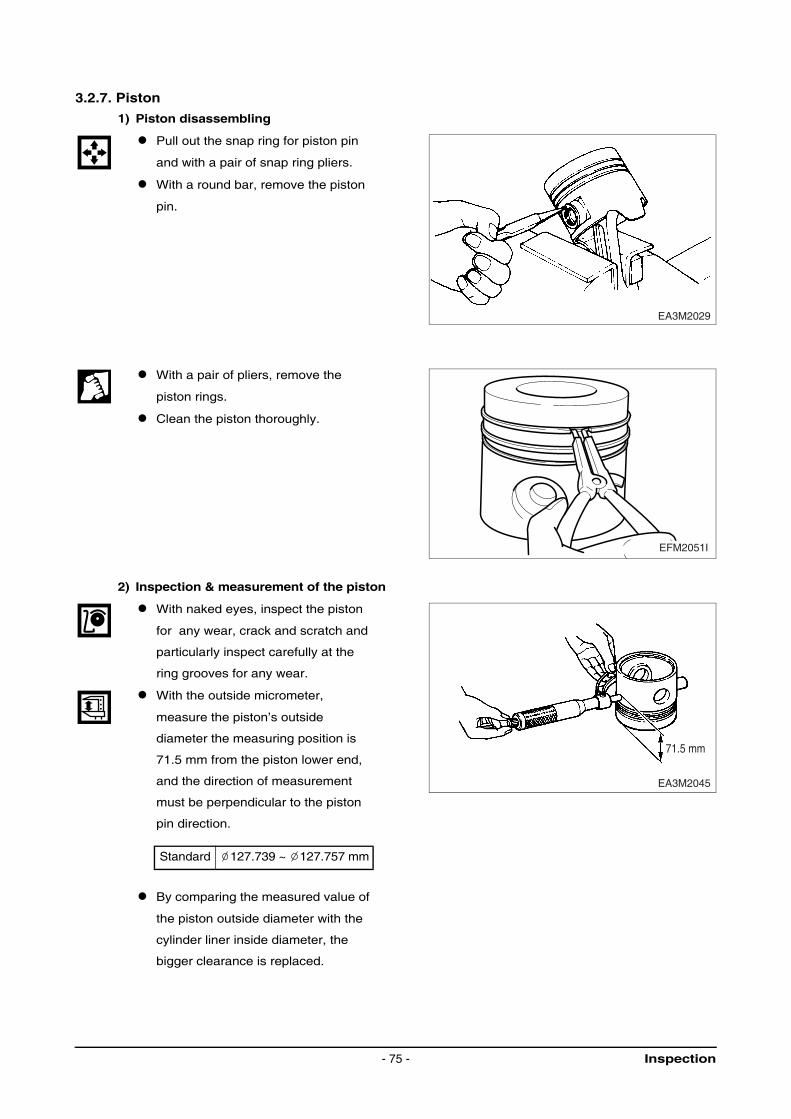
3.2.7. Piston
1) Piston disassembling
Pull out the snap ring for piston pin
and with a pair of snap ring pliers.
With a round bar, remove the piston
pin.
With a pair of pliers, remove the
piston rings.
Clean the piston thoroughly.
2) Inspection & measurement of the piston
With naked eyes, inspect the piston
for any wear, crack and scratch and
particularly inspect carefully at the
ring grooves for any wear.
With the outside micrometer,
measure the piston’s outside
diameter the measuring position is
71.5 mm from the piston lower end,
and the direction of measurement
must be perpendicular to the piston
pin direction.
By comparing the measured value of
the piston outside diameter with the
cylinder liner inside diameter, the
bigger clearance is replaced.
Standard 127.739 ~ 127.757 mm
EA3M2029
EFM2051I
71.5 mm
EA3M2045
Inspection- 75 -
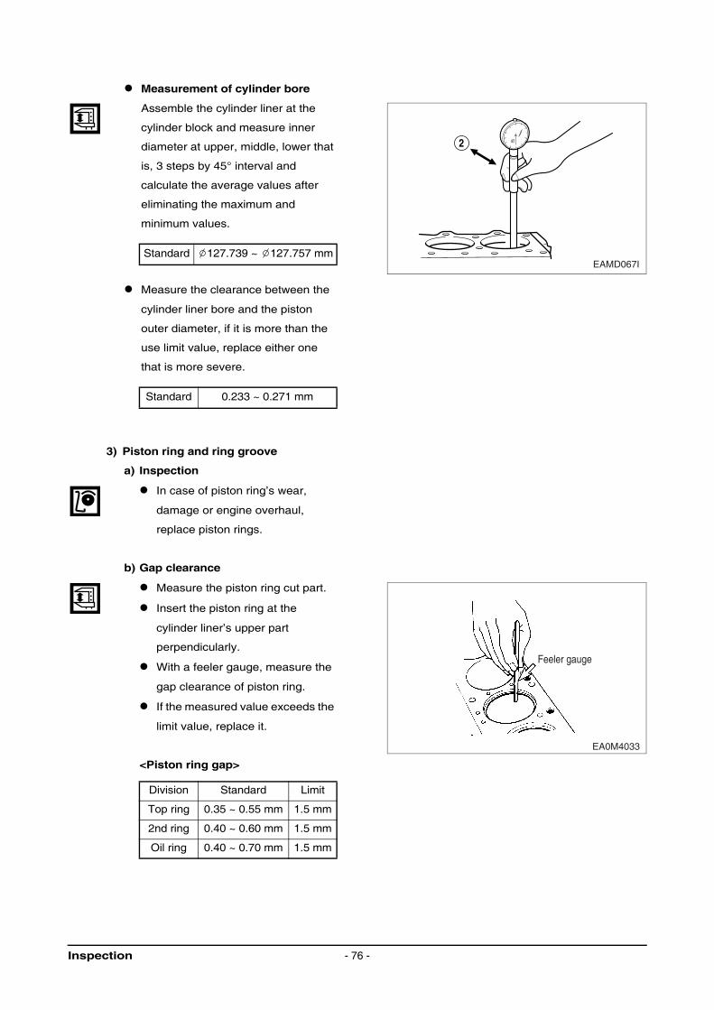
Measurement of cylinder bore
Assemble the cylinder liner at the
cylinder block and measure inner
diameter at upper, middle, lower that
is, 3 steps by 45° interval and
calculate the average values after
eliminating the maximum and
minimum values.
Measure the clearance between the
cylinder liner bore and the piston
outer diameter, if it is more than the
use limit value, replace either one
that is more severe.
3) Piston ring and ring groove
a) Inspection
In case of piston ring’s wear,
damage or engine overhaul,
replace piston rings.
b) Gap clearance
Measure the piston ring cut part.
Insert the piston ring at the
cylinder liner’s upper part
perpendicularly.
With a feeler gauge, measure the
gap clearance of piston ring.
If the measured value exceeds the
limit value, replace it.
<Piston ring gap>
Standard 127.739 ~ 127.757 mm
Standard 0.233 ~ 0.271 mm
Division Standard Limit
Top ring 0.35 ~ 0.55 mm 1.5 mm
2nd ring 0.40 ~ 0.60 mm 1.5 mm
Oil ring 0.40 ~ 0.70 mm 1.5 mm
2
EAMD067I
EA0M4033
Feeler gauge
Inspection - 76 -
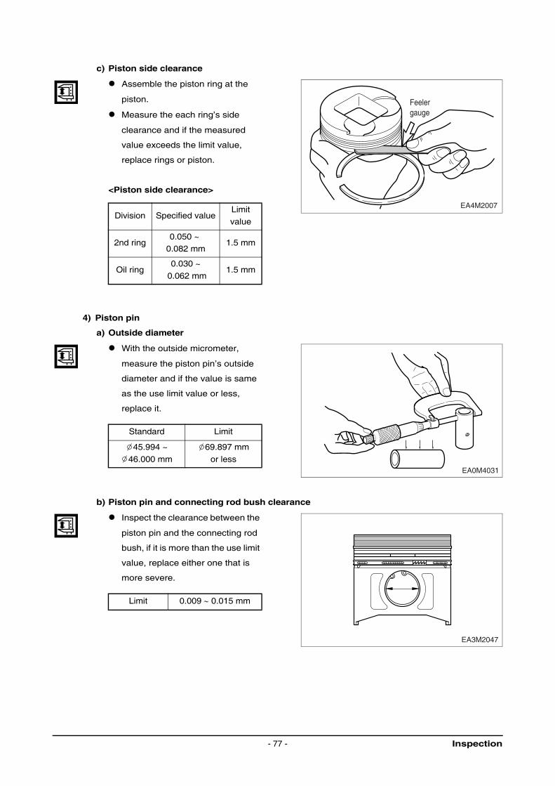
c) Piston side clearance
Assemble the piston ring at the
piston.
Measure the each ring’s side
clearance and if the measured
value exceeds the limit value,
replace rings or piston.
<Piston side clearance>
4) Piston pin
a) Outside diameter
With the outside micrometer,
measure the piston pin’s outside
diameter and if the value is same
as the use limit value or less,
replace it.
b) Piston pin and connecting rod bush clearance
Inspect the clearance between the
piston pin and the connecting rod
bush, if it is more than the use limit
value, replace either one that is
more severe.
Division Specified valueLimit
value
2nd ring0.050 ~
0.082 mm1.5 mm
Oil ring0.030 ~
0.062 mm1.5 mm
Standard Limit
45.994 ~
46.000 mm
69.897 mm
or less
Limit 0.009 ∼ 0.015 mm
EA4M2007
Feelergauge
EA0M4031
EA3M2047
Inspection- 77 -
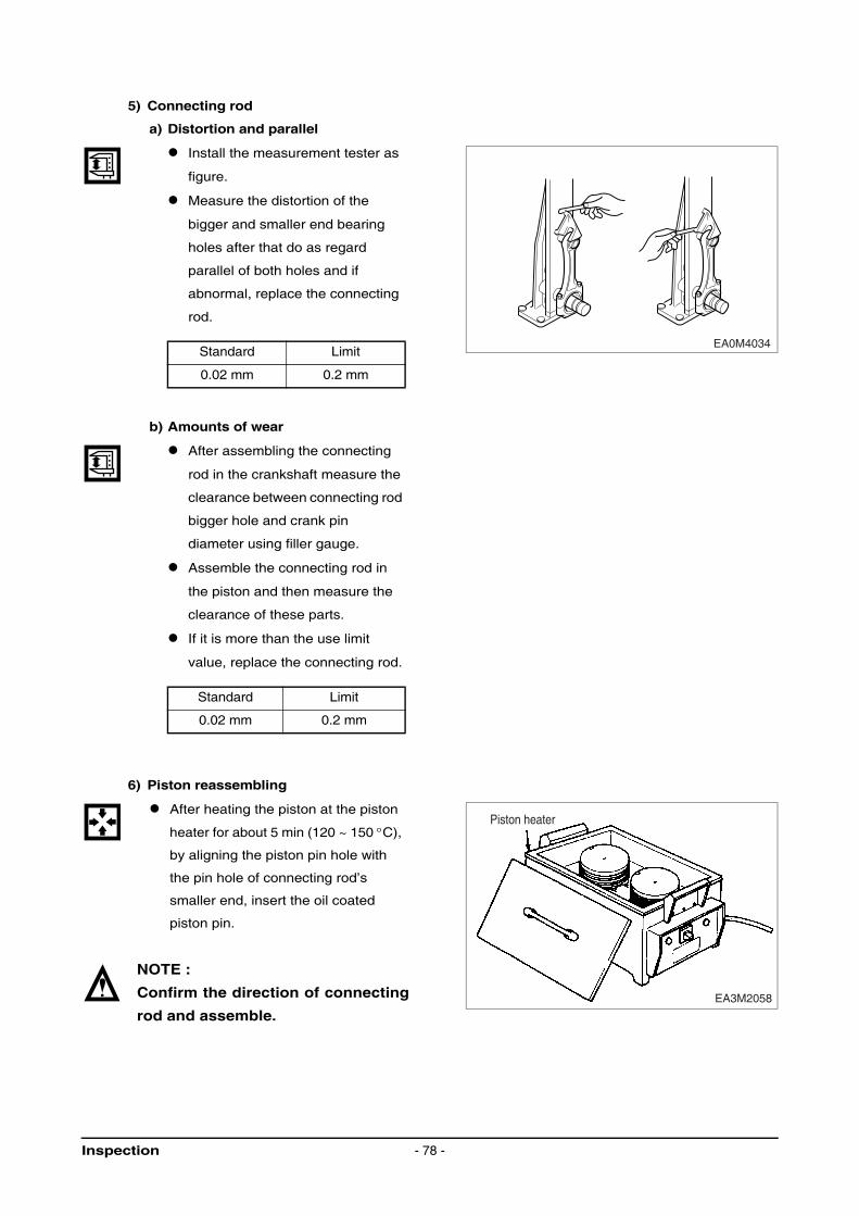
5) Connecting rod
a) Distortion and parallel
Install the measurement tester as
figure.
Measure the distortion of the
bigger and smaller end bearing
holes after that do as regard
parallel of both holes and if
abnormal, replace the connecting
rod.
b) Amounts of wear
After assembling the connecting
rod in the crankshaft measure the
clearance between connecting rod
bigger hole and crank pin
diameter using filler gauge.
Assemble the connecting rod in
the piston and then measure the
clearance of these parts.
If it is more than the use limit
value, replace the connecting rod.
6) Piston reassembling
After heating the piston at the piston
heater for about 5 min (120 ~ 150 °C),
by aligning the piston pin hole with
the pin hole of connecting rod’s
smaller end, insert the oil coated
piston pin.
NOTE :
Confirm the direction of connecting
rod and assemble.
Standard Limit
0.02 mm 0.2 mm
Standard Limit
0.02 mm 0.2 mm
EA0M4034
EA3M2058
Piston heater
Inspection - 78 -
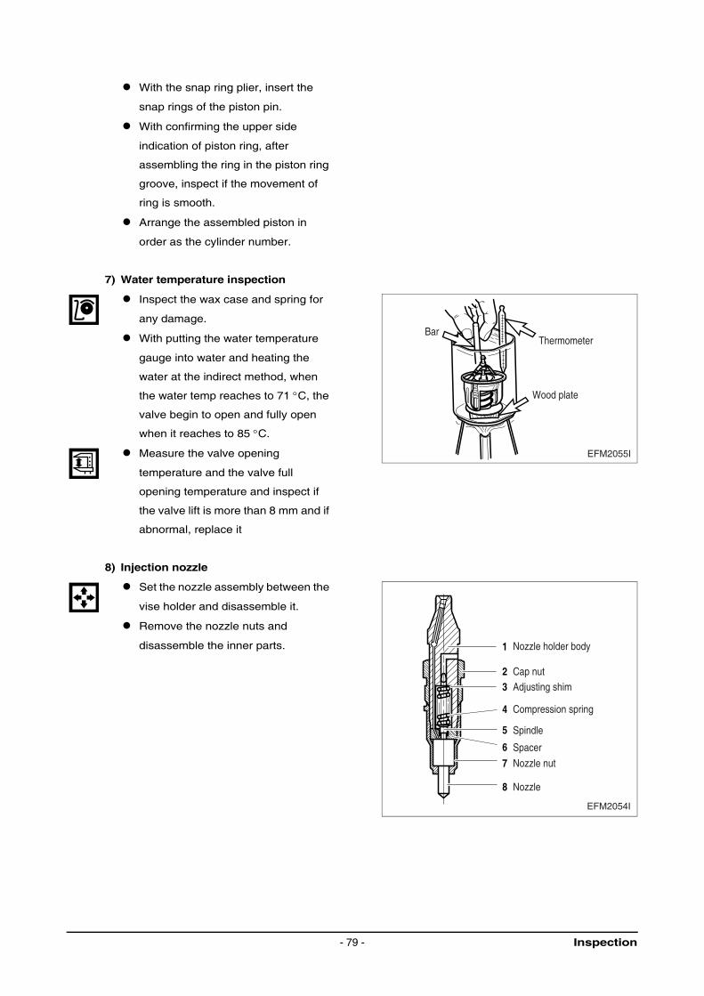
With the snap ring plier, insert the
snap rings of the piston pin.
With confirming the upper side
indication of piston ring, after
assembling the ring in the piston ring
groove, inspect if the movement of
ring is smooth.
Arrange the assembled piston in
order as the cylinder number.
7) Water temperature inspection
Inspect the wax case and spring for
any damage.
With putting the water temperature
gauge into water and heating the
water at the indirect method, when
the water temp reaches to 71 °C, the
valve begin to open and fully open
when it reaches to 85 °C.
Measure the valve opening
temperature and the valve full
opening temperature and inspect if
the valve lift is more than 8 mm and if
abnormal, replace it
8) Injection nozzle
Set the nozzle assembly between the
vise holder and disassemble it.
Remove the nozzle nuts and
disassemble the inner parts.
EFM2055I
Thermometer
Wood plate
Bar
1
2
4
5
7
8
6
3
EFM2054I
Nozzle holder body
Cap nutAdjusting shim
Compression spring
Spindle
Spacer
Nozzle nut
Nozzle
Inspection- 79 -
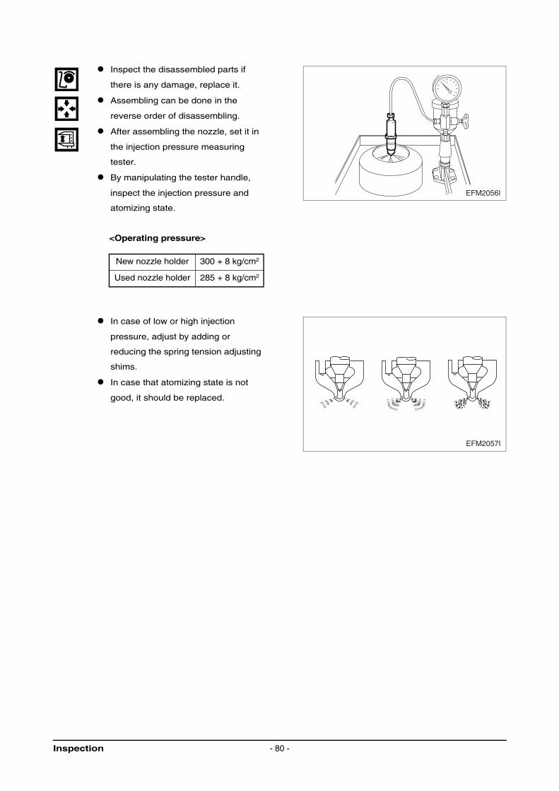
Inspect the disassembled parts if
there is any damage, replace it.
Assembling can be done in the
reverse order of disassembling.
After assembling the nozzle, set it in
the injection pressure measuring
tester.
By manipulating the tester handle,
inspect the injection pressure and
atomizing state.
<Operating pressure>
In case of low or high injection
pressure, adjust by adding or
reducing the spring tension adjusting
shims.
In case that atomizing state is not
good, it should be replaced.
New nozzle holder 300 + 8 kg/cm2
Used nozzle holder 285 + 8 kg/cm2
EFM2056I
EFM2057I
Inspection - 80 -
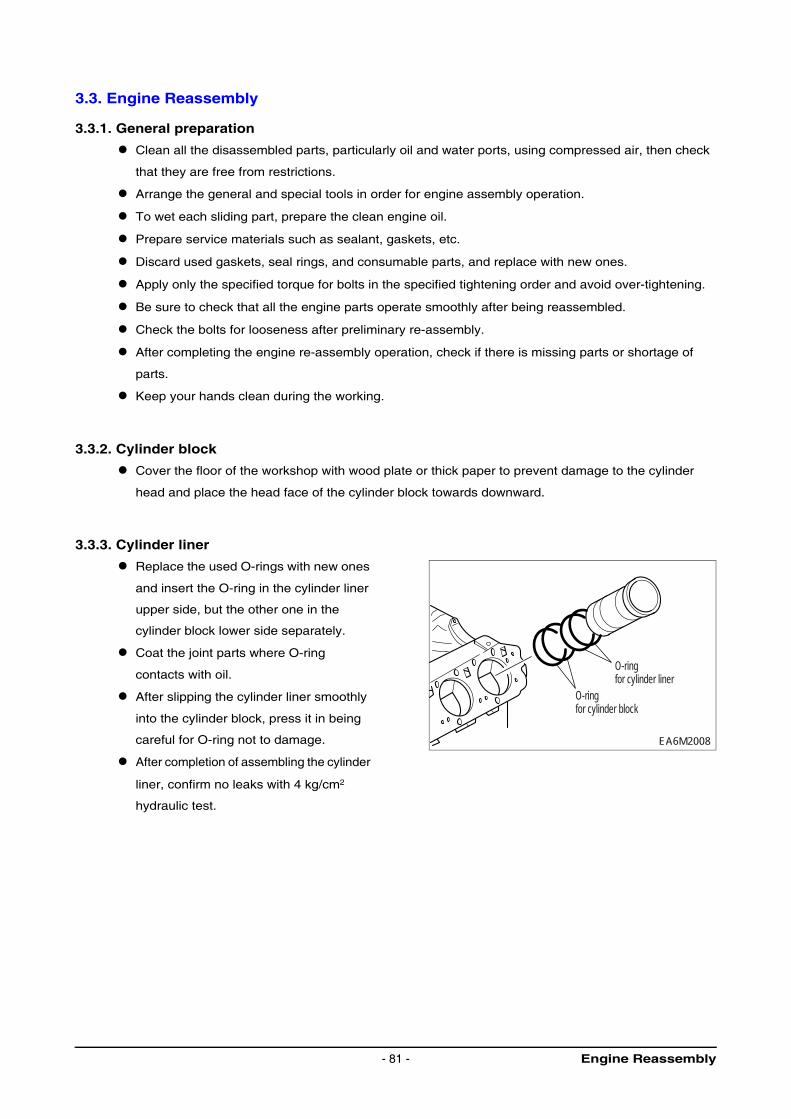
3.3. Engine Reassembly
3.3.1. General preparation
Clean all the disassembled parts, particularly oil and water ports, using compressed air, then check
that they are free from restrictions.
Arrange the general and special tools in order for engine assembly operation.
To wet each sliding part, prepare the clean engine oil.
Prepare service materials such as sealant, gaskets, etc.
Discard used gaskets, seal rings, and consumable parts, and replace with new ones.
Apply only the specified torque for bolts in the specified tightening order and avoid over-tightening.
Be sure to check that all the engine parts operate smoothly after being reassembled.
Check the bolts for looseness after preliminary re-assembly.
After completing the engine re-assembly operation, check if there is missing parts or shortage of
parts.
Keep your hands clean during the working.
3.3.2. Cylinder block
Cover the floor of the workshop with wood plate or thick paper to prevent damage to the cylinder
head and place the head face of the cylinder block towards downward.
3.3.3. Cylinder liner
Replace the used O-rings with new ones
and insert the O-ring in the cylinder liner
upper side, but the other one in the
cylinder block lower side separately.
Coat the joint parts where O-ring
contacts with oil.
After slipping the cylinder liner smoothly
into the cylinder block, press it in being
careful for O-ring not to damage.
After completion of assembling the cylinder
liner, confirm no leaks with 4 kg/cm2
hydraulic test.
EA6M2008
O-ringfor cylinder block
O-ringfor cylinder liner
Engine Reassembly- 81 -
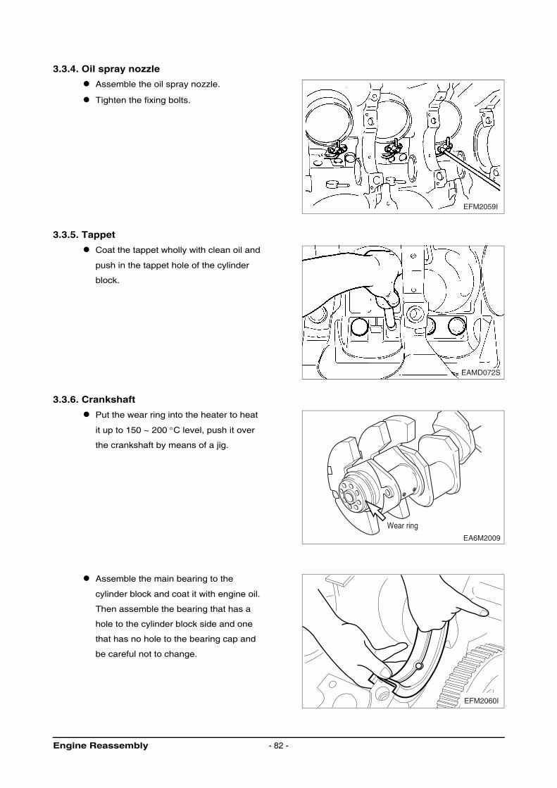
3.3.4. Oil spray nozzle
Assemble the oil spray nozzle.
Tighten the fixing bolts.
3.3.5. Tappet
Coat the tappet wholly with clean oil and
push in the tappet hole of the cylinder
block.
3.3.6. Crankshaft
Put the wear ring into the heater to heat
it up to 150 ~ 200 °C level, push it over
the crankshaft by means of a jig.
Assemble the main bearing to the
cylinder block and coat it with engine oil.
Then assemble the bearing that has a
hole to the cylinder block side and one
that has no hole to the bearing cap and
be careful not to change.
EFM2059I
EAMD072S
EA6M2009
Wear ring
EFM2060I
Engine Reassembly - 82 -
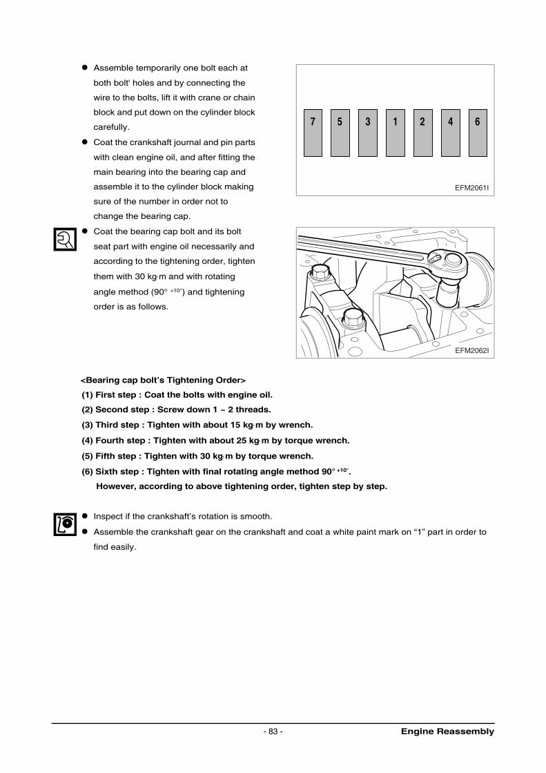
Assemble temporarily one bolt each at
both bolt' holes and by connecting the
wire to the bolts, lift it with crane or chain
block and put down on the cylinder block
carefully.
Coat the crankshaft journal and pin parts
with clean engine oil, and after fitting the
main bearing into the bearing cap and
assemble it to the cylinder block making
sure of the number in order not to
change the bearing cap.
Coat the bearing cap bolt and its bolt
seat part with engine oil necessarily and
according to the tightening order, tighten
them with 30 kg⋅m and with rotating
angle method (90° +10°) and tightening
order is as follows.
<Bearing cap bolt’s Tightening Order>
(1) First step : Coat the bolts with engine oil.
(2) Second step : Screw down 1 ~ 2 threads.
(3) Third step : Tighten with about 15 kg⋅m by wrench.
(4) Fourth step : Tighten with about 25 kg⋅m by torque wrench.
(5) Fifth step : Tighten with 30 kg⋅m by torque wrench.
(6) Sixth step : Tighten with final rotating angle method 90° +10°.
However, according to above tightening order, tighten step by step.
Inspect if the crankshaft’s rotation is smooth.
Assemble the crankshaft gear on the crankshaft and coat a white paint mark on “1” part in order to
find easily.
6421357
EFM2061I
EFM2062I
Engine Reassembly- 83 -
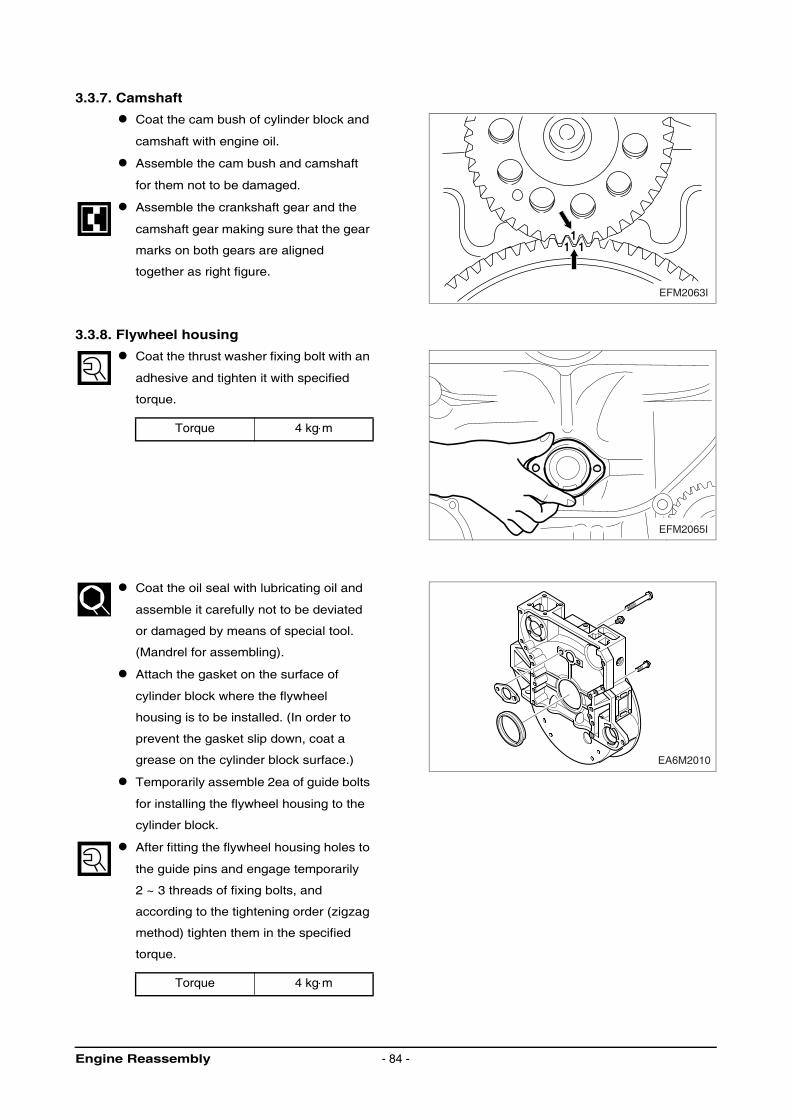
3.3.7. Camshaft
Coat the cam bush of cylinder block and
camshaft with engine oil.
Assemble the cam bush and camshaft
for them not to be damaged.
Assemble the crankshaft gear and the
camshaft gear making sure that the gear
marks on both gears are aligned
together as right figure.
3.3.8. Flywheel housing
Coat the thrust washer fixing bolt with an
adhesive and tighten it with specified
torque.
Coat the oil seal with lubricating oil and
assemble it carefully not to be deviated
or damaged by means of special tool.
(Mandrel for assembling).
Attach the gasket on the surface of
cylinder block where the flywheel
housing is to be installed. (In order to
prevent the gasket slip down, coat a
grease on the cylinder block surface.)
Temporarily assemble 2ea of guide bolts
for installing the flywheel housing to the
cylinder block.
After fitting the flywheel housing holes to
the guide pins and engage temporarily
2 ~ 3 threads of fixing bolts, and
according to the tightening order (zigzag
method) tighten them in the specified
torque.
Torque 4 kg⋅m
Torque 4 kg⋅m
1 11
EFM2063I
EFM2065I
EA6M2010
Engine Reassembly - 84 -
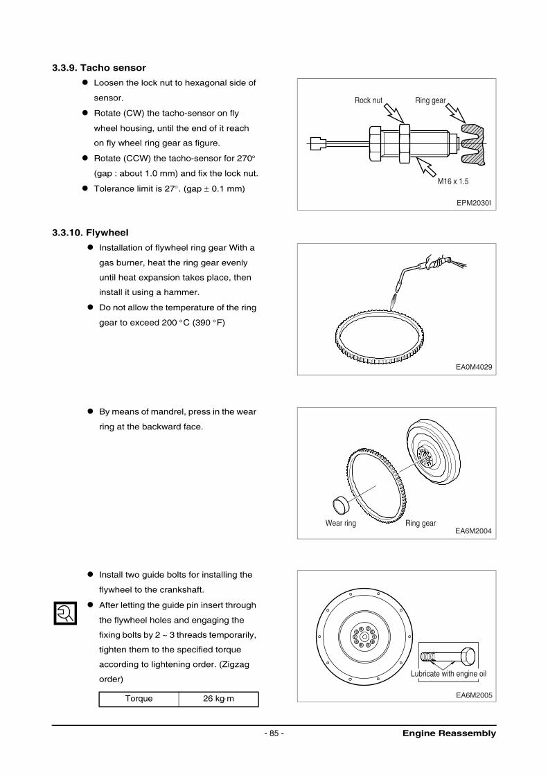
3.3.9. Tacho sensor
Loosen the lock nut to hexagonal side of
sensor.
Rotate (CW) the tacho-sensor on fly
wheel housing, until the end of it reach
on fly wheel ring gear as figure.
Rotate (CCW) the tacho-sensor for 270°
(gap : about 1.0 mm) and fix the lock nut.
Tolerance limit is 27°. (gap ± 0.1 mm)
3.3.10. Flywheel
Installation of flywheel ring gear With a
gas burner, heat the ring gear evenly
until heat expansion takes place, then
install it using a hammer.
Do not allow the temperature of the ring
gear to exceed 200 °C (390 °F)
By means of mandrel, press in the wear
ring at the backward face.
Install two guide bolts for installing the
flywheel to the crankshaft.
After letting the guide pin insert through
the flywheel holes and engaging the
fixing bolts by 2 ~ 3 threads temporarily,
tighten them to the specified torque
according to lightening order. (Zigzag
order)
Torque 26 kg⋅m
EPM2030I
Rock nut Ring gear
M16 x 1.5
EA0M4029
EA6M2004Wear ring Ring gear
EA6M2005
49 5
6 10
7
8
2 1
3
Lubricate with engine oil
Engine Reassembly- 85 -
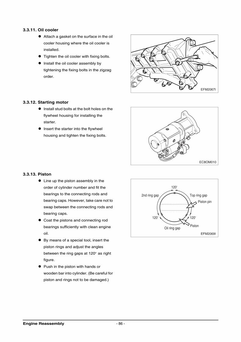
3.3.11. Oil cooler
Attach a gasket on the surface in the oil
cooler housing where the oil cooler is
installed.
Tighten the oil cooler with fixing bolts.
Install the oil cooler assembly by
tightening the fixing bolts in the zigzag
order.
3.3.12. Starting motor
Install stud bolts at the bolt holes on the
flywheel housing for installing the
starter.
Insert the starter into the flywheel
housing and tighten the fixing bolts.
3.3.13. Piston
Line up the piston assembly in the
order of cylinder number and fit the
bearings to the connecting rods and
bearing caps. However, take care not to
swap between the connecting rods and
bearing caps.
Coat the pistons and connecting rod
bearings sufficiently with clean engine
oil.
By means of a special tool, insert the
piston rings and adjust the angles
between the ring gaps at 120° as right
figure.
Push in the piston with hands or
wooden bar into cylinder. (Be careful for
piston and rings not to be damaged.)
EFM2067I
EC8OM010
EFM2069I
120O
120O 120O
2nd ring gap Top ring gap
Oil ring gapPiston
Piston pin
Engine Reassembly - 86 -
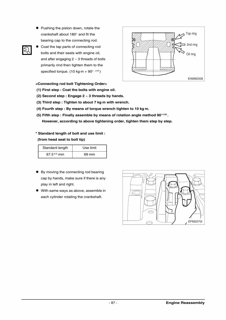
Pushing the piston down, rotate the
crankshaft about 180° and fit the
bearing cap to the connecting rod.
Coat the tap parts of connecting rod
bolts and their seats with engine oil,
and after engaging 2 ~ 3 threads of bolts
primarily rind then tighten them to the
specified torque. (10 kg⋅m + 90° +10°)
<Connecting rod bolt Tightening Order>
(1) First step : Coat the bolts with engine oil.
(2) Second step : Engage 2 ~ 3 threads by hands.
(3) Third step : Tighten to about 7 kg⋅m with wrench.
(4) Fourth step : By means of torque wrench tighten to 10 kg⋅m.
(5) Fifth step : Finally assemble by means of rotation angle method 90°+10°.
However, according to above tightening order, tighten them step by step.
* Standard length of bolt and use limit :
(from head seat to bolt tip)
By moving the connecting rod bearing
cap by hands, make sure if there is any
play in left and right.
With same ways as above, assemble in
each cylinder rotating the crankshaft.
Standard length Use limit
67.5-0.3 mm 69 mm
EA6M2006
Top ring
2nd ring
Oil ring
EFM2070I
Engine Reassembly- 87 -
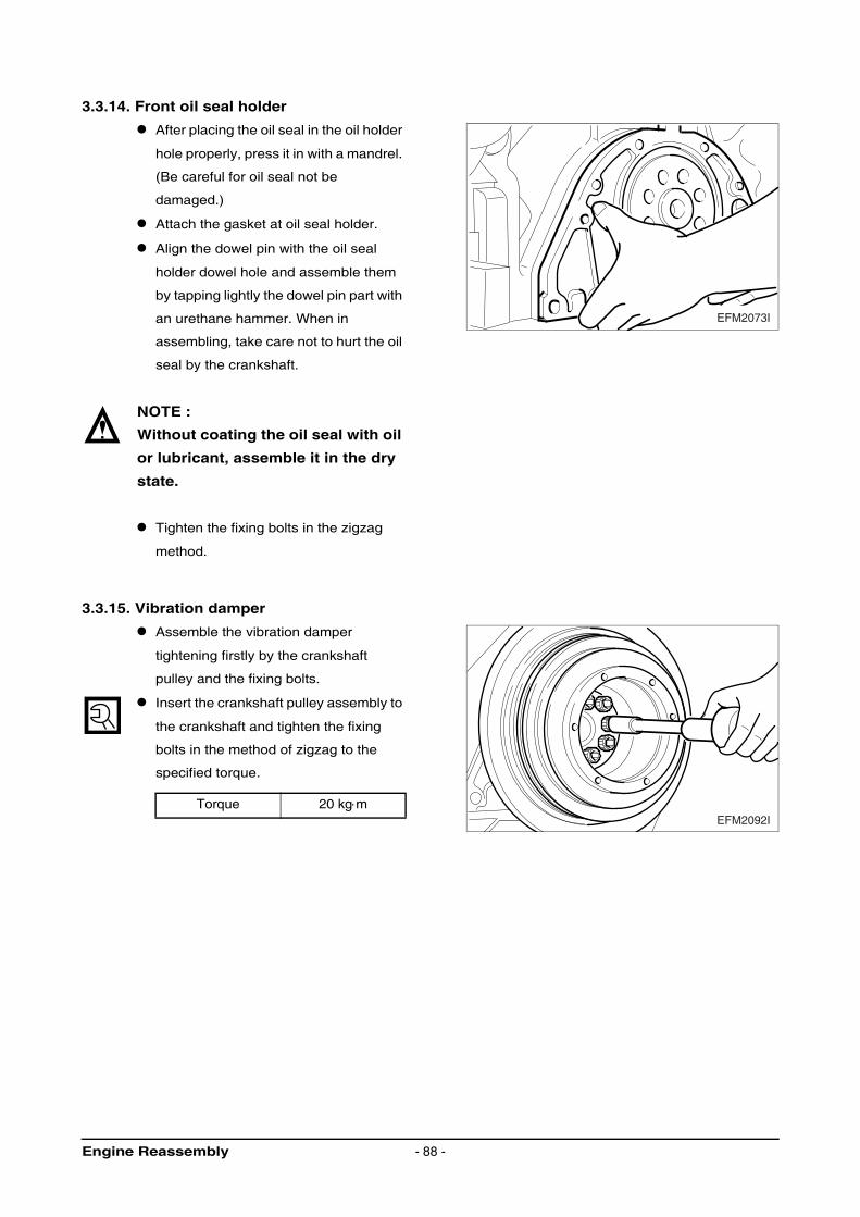
3.3.14. Front oil seal holder
After placing the oil seal in the oil holder
hole properly, press it in with a mandrel.
(Be careful for oil seal not be
damaged.)
Attach the gasket at oil seal holder.
Align the dowel pin with the oil seal
holder dowel hole and assemble them
by tapping lightly the dowel pin part with
an urethane hammer. When in
assembling, take care not to hurt the oil
seal by the crankshaft.
NOTE :
Without coating the oil seal with oil
or lubricant, assemble it in the dry
state.
Tighten the fixing bolts in the zigzag
method.
3.3.15. Vibration damper
Assemble the vibration damper
tightening firstly by the crankshaft
pulley and the fixing bolts.
Insert the crankshaft pulley assembly to
the crankshaft and tighten the fixing
bolts in the method of zigzag to the
specified torque.
Torque 20 kg⋅m
EFM2073I
EFM2092I
Engine Reassembly - 88 -
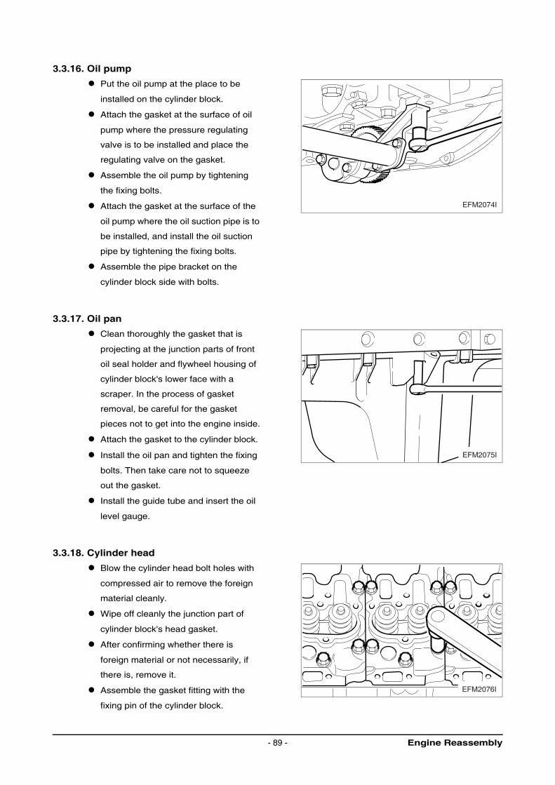
3.3.16. Oil pump
Put the oil pump at the place to be
installed on the cylinder block.
Attach the gasket at the surface of oil
pump where the pressure regulating
valve is to be installed and place the
regulating valve on the gasket.
Assemble the oil pump by tightening
the fixing bolts.
Attach the gasket at the surface of the
oil pump where the oil suction pipe is to
be installed, and install the oil suction
pipe by tightening the fixing bolts.
Assemble the pipe bracket on the
cylinder block side with bolts.
3.3.17. Oil pan
Clean thoroughly the gasket that is
projecting at the junction parts of front
oil seal holder and flywheel housing of
cylinder block's lower face with a
scraper. In the process of gasket
removal, be careful for the gasket
pieces not to get into the engine inside.
Attach the gasket to the cylinder block.
Install the oil pan and tighten the fixing
bolts. Then take care not to squeeze
out the gasket.
Install the guide tube and insert the oil
level gauge.
3.3.18. Cylinder head
Blow the cylinder head bolt holes with
compressed air to remove the foreign
material cleanly.
Wipe off cleanly the junction part of
cylinder block's head gasket.
After confirming whether there is
foreign material or not necessarily, if
there is, remove it.
Assemble the gasket fitting with the
fixing pin of the cylinder block.
EFM2074I
EFM2075I
EFM2076I
Engine Reassembly- 89 -
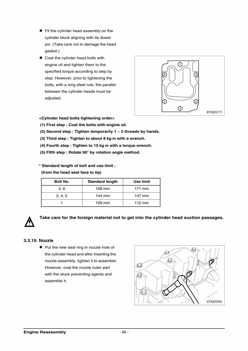
Fit the cylinder head assembly on the
cylinder block aligning with its dowel
pin. (Take care not to damage the head
gasket.)
Coat the cylinder head bolts with
engine oil and tighten them to the
specified torque according to step by
step. However, prior to tightening the
bolts, with a long steel rule, the parallel
between the cylinder heads must be
adjusted.
<Cylinder head bolts tightening order>
(1) First step : Coat the bolts with engine oil.
(2) Second step : Tighten temporarily 1 ~ 2 threads by hands.
(3) Third step : Tighten to about 8 kg⋅m with a wrench.
(4) Fourth step : Tighten to 15 kg⋅m with a torque wrench.
(5) Fifth step : Rotate 90° by rotation angle method.
* Standard length of bolt and use limit :
(from the head seat face to tip)
Take care for the foreign material not to get into the cylinder head suction passages.
3.3.19. Nozzle
Put the new seal ring in nozzle hole of
the cylinder head and after inserting the
nozzle assembly, tighten it to assemble
However, coat the nozzle outer part
with the stuck preventing agents and
assemble it.
Bolt No. Standard length Use limit
3, 6 168 mm 171 mm
2, 4, 5 144 mm 147 mm
1 109 mm 112 mm
4
2
1
6
5
3
EFM2077I
EFM2090I
Engine Reassembly - 90 -

3.3.20. Rocker arm
Coat the push rod with engine oil and
put it into the push rod hole.
Make a position the rocker arm
assembly on the cylinder head and
tighten the fixing bolts to the specified
tightening torque.
Adjust the valve clearance.
Regarding the adjustment, refer to the
regular maintenance part.
3.3.21. Checking and adjusting valve clearance
After removing the head cover loosen
the lock nuts of rocker arm adjusting
screws using a spanner and push the
filler gauge of specified value between
rocker arm and valve stem.
Tighten the adjusting screw using a
driver until the inserted feeler gauge
can be taken a slight resistance
between the valve stem and the rocker
arm. Then tighten the lock nut
simultaneously on not moving the
adjusting screw.
After checking the clearance once more
if necessary re-adjust it.
3.3.22. Cylinder head cover
Attach the new gasket on the surface of
cylinder head where the cover is to be
installed.
Assemble the cylinder head cover by
tightening the fixing bolts.
Insert the oil filler cap.
Torque 6.5 kg⋅m
EFM2091I
EBO4007S21 3
EFM2020I
Engine Reassembly- 91 -
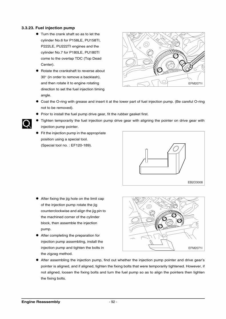
3.3.23. Fuel injection pump
Turn the crank shaft so as to let the
cylinder No.6 for P158LE, PU158TI,
P222LE, PU222TI engines and the
cylinder No.7 for P180LE, PU180TI
come to the overlap TDC (Top Dead
Center).
Rotate the crankshaft to reverse about
30° (in order to remove a backlash),
and then rotate it to engine rotating
direction to set the fuel injection timing
angle.
Coat the O-ring with grease and insert it at the lower part of fuel injection pump. (Be careful O-ring
not to be removed).
Prior to install the fuel pump drive gear, fit the rubber gasket first.
Tighten temporarily the fuel injection pump drive gear with aligning the pointer on drive gear with
injection pump pointer.
Fit the injection pump in the appropriate
position using a special tool.
(Special tool no. : EF120-189).
After fixing the jig hole on the limit cap
of the injection pump rotate the jig
counterclockwise and align the jig pin to
the machined corner of the cylinder
block, then assemble the injection
pump.
After completing the preparation for
injection pump assembling, install the
injection pump and tighten the bolts in
the zigzag method.
After assembling the injection pump, find out whether the injection pump pointer and drive gear’s
pointer is aligned, and if aligned, tighten the fixing bolts that were temporarily tightened. However, if
not aligned, loosen the fixing bolts and turn the fuel pump so as to align the pointers then tighten
the fixing bolts.
EFM2071I
EB2O3008
EFM2071I
Engine Reassembly - 92 -
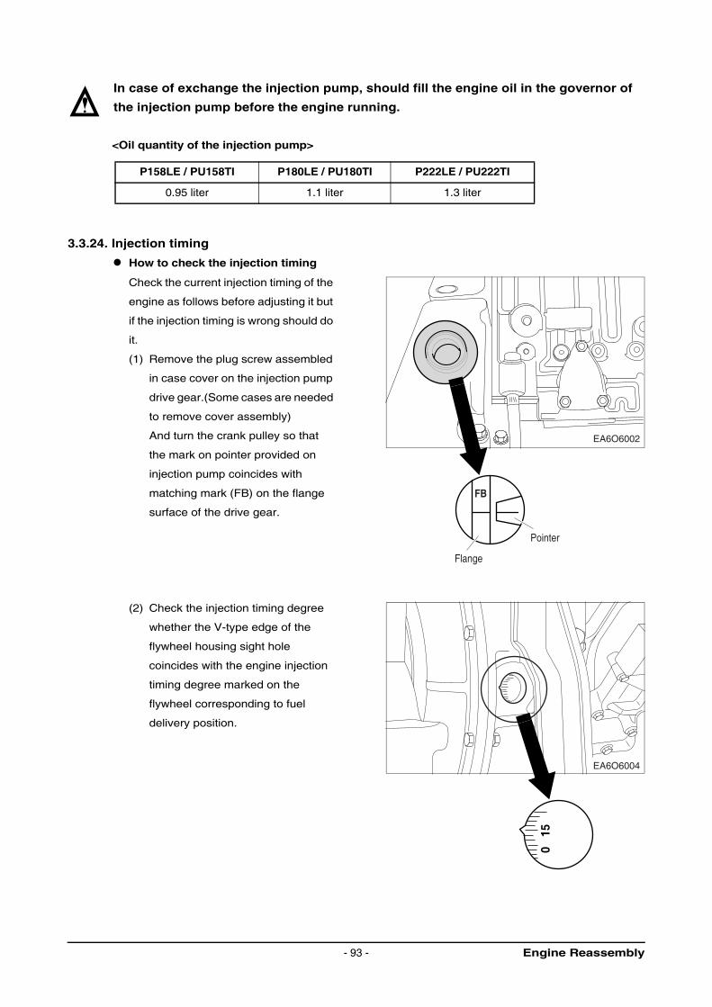
In case of exchange the injection pump, should fill the engine oil in the governor of
the injection pump before the engine running.
<Oil quantity of the injection pump>
3.3.24. Injection timing
How to check the injection timing
Check the current injection timing of the
engine as follows before adjusting it but
if the injection timing is wrong should do
it.
(1) Remove the plug screw assembled
in case cover on the injection pump
drive gear.(Some cases are needed
to remove cover assembly)
And turn the crank pulley so that
the mark on pointer provided on
injection pump coincides with
matching mark (FB) on the flange
surface of the drive gear.
(2) Check the injection timing degree
whether the V-type edge of the
flywheel housing sight hole
coincides with the engine injection
timing degree marked on the
flywheel corresponding to fuel
delivery position.
P158LE / PU158TI P180LE / PU180TI P222LE / PU222TI
0.95 liter 1.1 liter 1.3 liter
EA6O6002
EA6O6004
Flange
Pointer
FB
150
Engine Reassembly- 93 -
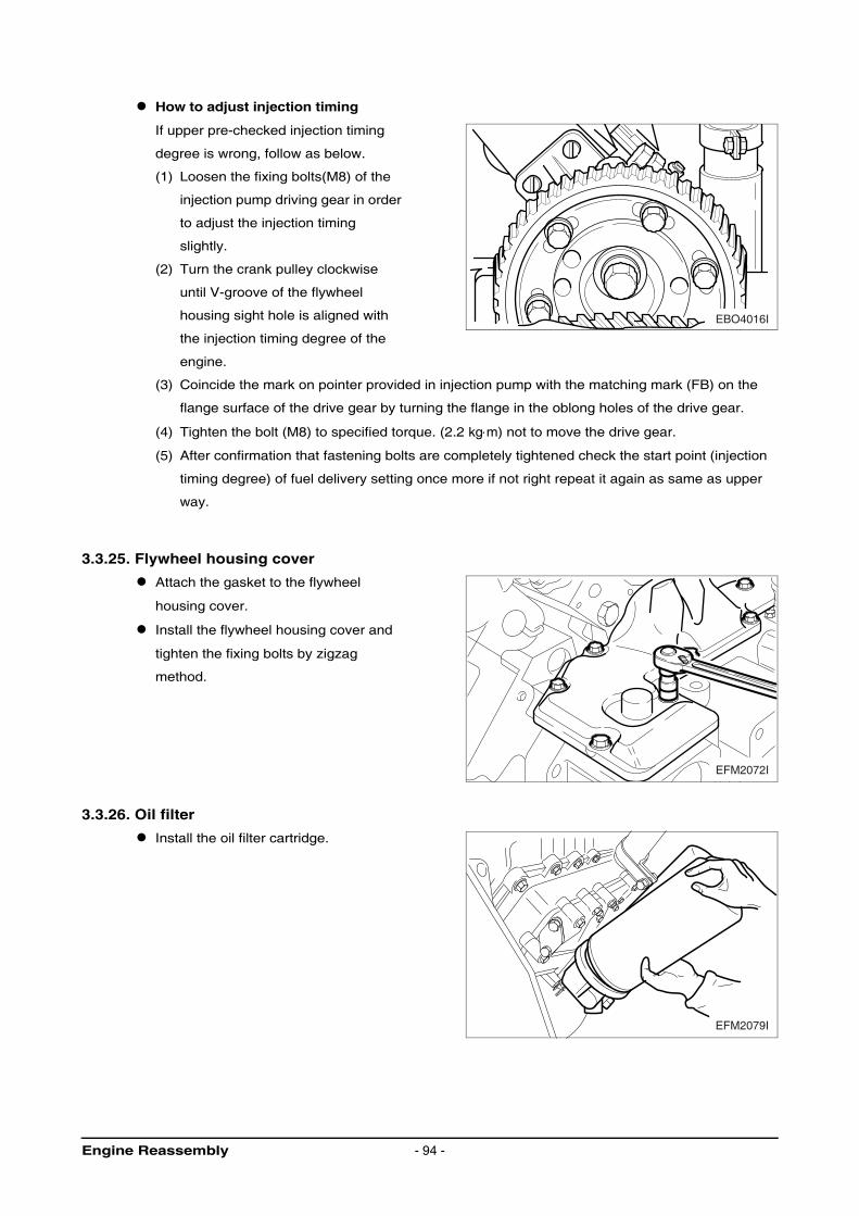
How to adjust injection timing
If upper pre-checked injection timing
degree is wrong, follow as below.
(1) Loosen the fixing bolts(M8) of the
injection pump driving gear in order
to adjust the injection timing
slightly.
(2) Turn the crank pulley clockwise
until V-groove of the flywheel
housing sight hole is aligned with
the injection timing degree of the
engine.
(3) Coincide the mark on pointer provided in injection pump with the matching mark (FB) on the
flange surface of the drive gear by turning the flange in the oblong holes of the drive gear.
(4) Tighten the bolt (M8) to specified torque. (2.2 kg⋅m) not to move the drive gear.
(5) After confirmation that fastening bolts are completely tightened check the start point (injection
timing degree) of fuel delivery setting once more if not right repeat it again as same as upper
way.
3.3.25. Flywheel housing cover
Attach the gasket to the flywheel
housing cover.
Install the flywheel housing cover and
tighten the fixing bolts by zigzag
method.
3.3.26. Oil filter
Install the oil filter cartridge.
EBO4016I
EFM2072I
EFM2079I
Engine Reassembly - 94 -
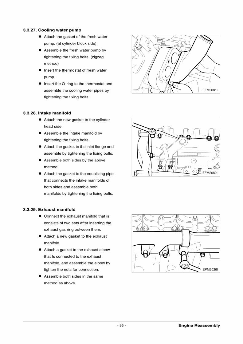
3.3.27. Cooling water pump
Attach the gasket of the fresh water
pump. (at cylinder block side)
Assemble the fresh water pump by
tightening the fixing bolts. (zigzag
method)
Insert the thermostat of fresh water
pump.
Insert the O-ring to the thermostat and
assemble the cooling water pipes by
tightening the fixing bolts.
3.3.28. Intake manifold
Attach the new gasket to the cylinder
head side.
Assemble the intake manifold by
tightening the fixing bolts.
Attach the gasket to the inlet flange and
assemble by tightening the fixing bolts.
Assemble both sides by the above
method.
Attach the gasket to the equalizing pipe
that connects the intake manifolds of
both sides and assemble both
manifolds by tightening the fixing bolts.
3.3.29. Exhaust manifold
Connect the exhaust manifold that is
consists of two sets after inserting the
exhaust gas ring between them.
Attach a new gasket to the exhaust
manifold.
Attach a gasket to the exhaust elbow
that Is connected to the exhaust
manifold, and assemble the elbow by
tighten the nuts for connection.
Assemble both sides in the same
method as above.
EFM2081I
EFM2082I
EPM2026I
Engine Reassembly- 95 -
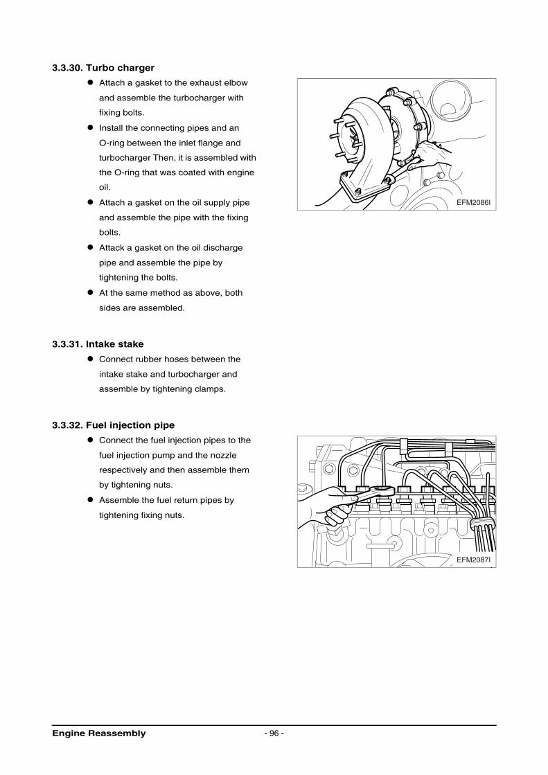
3.3.30. Turbo charger
Attach a gasket to the exhaust elbow
and assemble the turbocharger with
fixing bolts.
Install the connecting pipes and an
O-ring between the inlet flange and
turbocharger Then, it is assembled with
the O-ring that was coated with engine
oil.
Attach a gasket on the oil supply pipe
and assemble the pipe with the fixing
bolts.
Attack a gasket on the oil discharge
pipe and assemble the pipe by
tightening the bolts.
At the same method as above, both
sides are assembled.
3.3.31. Intake stake
Connect rubber hoses between the
intake stake and turbocharger and
assemble by tightening clamps.
3.3.32. Fuel injection pipe
Connect the fuel injection pipes to the
fuel injection pump and the nozzle
respectively and then assemble them
by tightening nuts.
Assemble the fuel return pipes by
tightening fixing nuts.
EFM2086I
EFM2087I
Engine Reassembly - 96 -
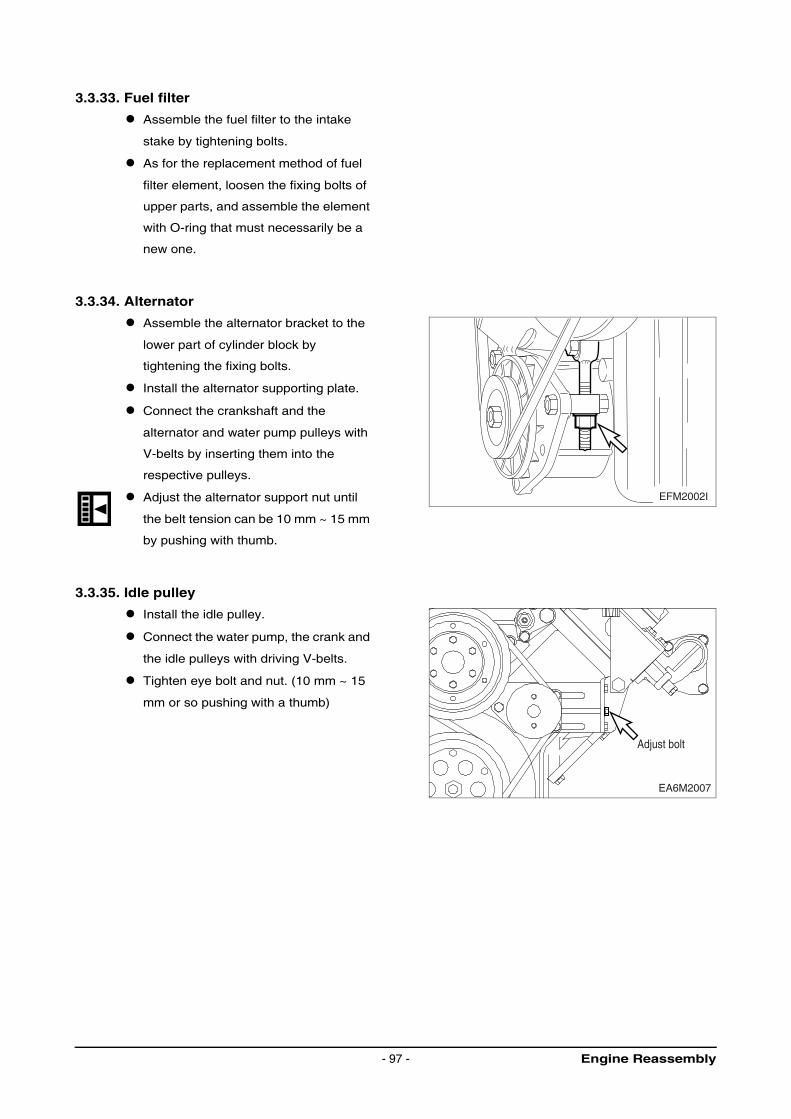
3.3.33. Fuel filter
Assemble the fuel filter to the intake
stake by tightening bolts.
As for the replacement method of fuel
filter element, loosen the fixing bolts of
upper parts, and assemble the element
with O-ring that must necessarily be a
new one.
3.3.34. Alternator
Assemble the alternator bracket to the
lower part of cylinder block by
tightening the fixing bolts.
Install the alternator supporting plate.
Connect the crankshaft and the
alternator and water pump pulleys with
V-belts by inserting them into the
respective pulleys.
Adjust the alternator support nut until
the belt tension can be 10 mm ~ 15 mm
by pushing with thumb.
3.3.35. Idle pulley
Install the idle pulley.
Connect the water pump, the crank and
the idle pulleys with driving V-belts.
Tighten eye bolt and nut. (10 mm ~ 15
mm or so pushing with a thumb)
EFM2002I
EA6M2007
Adjust bolt
Engine Reassembly- 97 -
Breaking-In - 98 -
3.4. Breaking-In
3.4.1. Operation of a new engine (Break-In)
Because the sliding surfaces of a new engine are not lapped enough, the oil film can be destroyed
easily by overload or overspeed and the engine life-time may be shortened.
Therefore the following things must be obeyed by all means.
Up to the first 50 hours
Engine should be run at fast idling until the temperature of the engine becomes normal operating
condition.
Overload or continuous high speed operation should be avoided.
High speed operation with no load should be prevented.
Abrupt start and stop of the engine should be avoided.
Engine speed must be under 70 % of its maximum speed.
Maintenance and inspection must be accomplished thoroughly.
3.4.2. Check points for break-in
During the break-in (the initial running of the engine) period, be particularly observant as follows :
1) Check engine oil level frequently. Maintain oil level in the safe range, between the “min.” and “max.”
marks on dipstick.
NOTE :
If you have a problem getting a good oil level reading on dipstick, rotate dipstick 180°
and re-insert for check.
2) Watch the oil pressure warning lamp. If the lamp blinks, it may be the oil pick-up screen is not
covered with oil. Check oil dipstick. Add oil to the oil pan, if required. Do not overfill. If level is correct
and the status still exists, see your DEALER for possible switch or oil pump and line malfunction.
NOTE :
Oil pressure will rise as RPM increases, and fall as RPM decreases. In addition, cold
oil will generally show higher oil pressure for any specific RPM than hot oil. Both of
these conditions reflect normal engine operation.
3) Watch the engine water temperature gauge and be sure there is proper water circulation. The water
temperature gauge needle will fluctuate if water level in expansion tank is too low.
At the end of the break-in period, remove break-in oil and replace the oil filter. Fill oil pan with
recommended engine oil. Refer to following table.
<Engine Oil capacity>
Oil pan (only)
P158LE / PU158TI 21 liter
P180LE / PU180TI 35 liter
P222LE / PU222TI 40 liter
4. Commissioning and Operation
4.1. Preparations
Before daily starting the engine, check fuel level, coolant level and engine oil level and replenish, if
necessary.
The notches in the dipstick indicate the highest and lowest permissible oil levels.
CAUTION :
Do not add so much engine oil that the oil level rises above the max. marking on the
dipstick. Overfilling will result in damage to the engine.
The oil required in the sump is specified in the “Engine Specification” at the head of these instructions.
NOTE :
The oil required to fill the oil filters and pipes depends upon the engine equipment
and use and must be determined individually at the time of initial commissioning.
(Make a note of the determined quantity).
Ensure outpost cleanliness when handling fuels, lubricants and coolants.
Use approved fuels, lubricants and coolants only, as otherwise the manufacturer’s guarantee will be
null and void.
4.2. Starting
Insert key in starting lock.
Moving control lever to “Idle speed”.
Key switch rotate clockwise.
Do not operate for longer than 10 seconds at a time.
After ignition of the engine, take-off the hands in key switch.
And adjust control lever for desired speed.
If engine fails to start, release the key, wait about 1 minute, then operate starter again.
Avoid running the cold engine for any length of time since in any internal combustion engine this is
liable to cause increased wear due to corrosion. Prolonged idling is harmful to the environment.
NOTE :
On initial start of an overhauled engine or after long periods without use, press shut-
down lever in “stop” position and operate starter motor for a few seconds (max. 10)
until oil pressure is indicated.
Only then the engine should be started in the normal way
Commissioning and Operation- 99 -
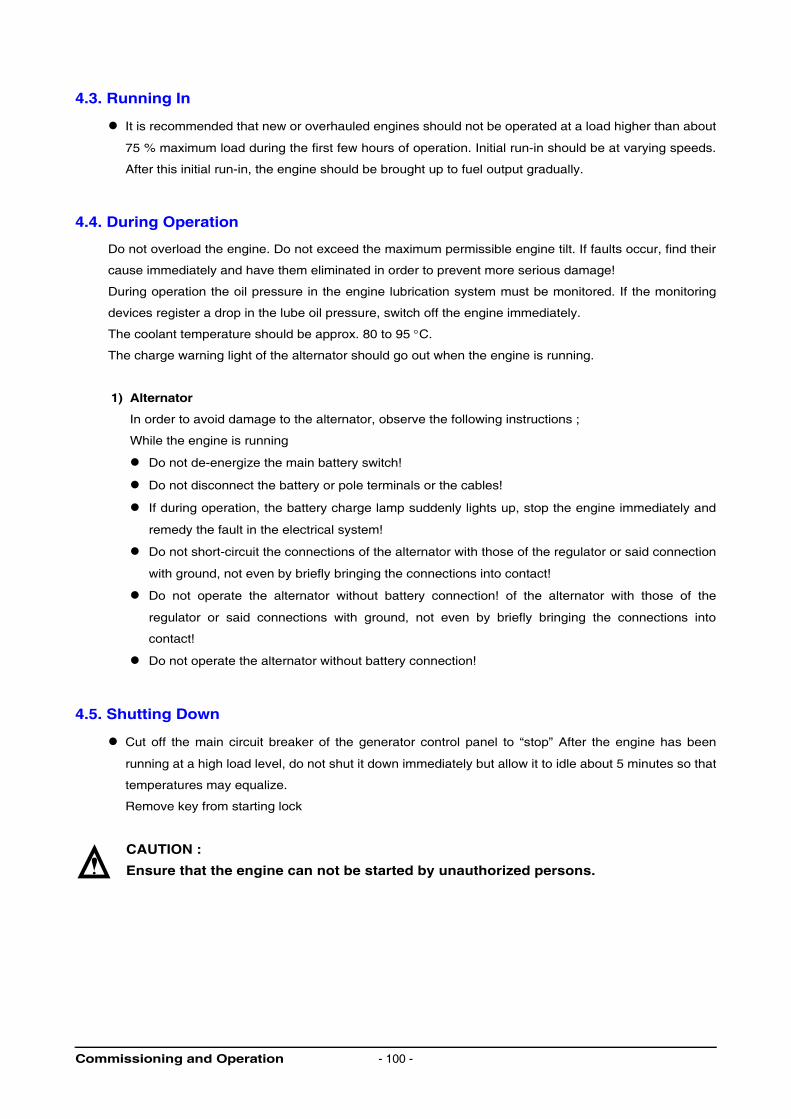
4.3. Running In
It is recommended that new or overhauled engines should not be operated at a load higher than about
75 % maximum load during the first few hours of operation. Initial run-in should be at varying speeds.
After this initial run-in, the engine should be brought up to fuel output gradually.
4.4. During Operation
Do not overload the engine. Do not exceed the maximum permissible engine tilt. If faults occur, find their
cause immediately and have them eliminated in order to prevent more serious damage!
During operation the oil pressure in the engine lubrication system must be monitored. If the monitoring
devices register a drop in the lube oil pressure, switch off the engine immediately.
The coolant temperature should be approx. 80 to 95 °C.
The charge warning light of the alternator should go out when the engine is running.
1) Alternator
In order to avoid damage to the alternator, observe the following instructions ;
While the engine is running
Do not de-energize the main battery switch!
Do not disconnect the battery or pole terminals or the cables!
If during operation, the battery charge lamp suddenly lights up, stop the engine immediately and
remedy the fault in the electrical system!
Do not short-circuit the connections of the alternator with those of the regulator or said connection
with ground, not even by briefly bringing the connections into contact!
Do not operate the alternator without battery connection! of the alternator with those of the
regulator or said connections with ground, not even by briefly bringing the connections into
contact!
Do not operate the alternator without battery connection!
4.5. Shutting Down
Cut off the main circuit breaker of the generator control panel to “stop” After the engine has been
running at a high load level, do not shut it down immediately but allow it to idle about 5 minutes so that
temperatures may equalize.
Remove key from starting lock
CAUTION :
Ensure that the engine can not be started by unauthorized persons.
Commissioning and Operation - 100 -
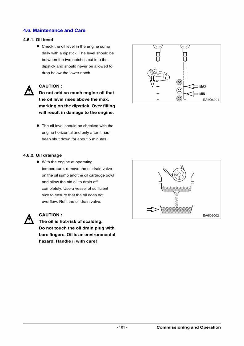
4.6. Maintenance and Care
4.6.1. Oil level
Check the oil level in the engine sump
daily with a dipstick. The level should be
between the two notches cut into the
dipstick and should never be allowed to
drop below the lower notch.
CAUTION :
Do not add so much engine oil that
the oil level rises above the max.
marking on the dipstick. Over filling
will result in damage to the engine.
The oil level should be checked with the
engine horizontal and only after it has
been shut down for about 5 minutes.
4.6.2. Oil drainage
With the engine at operating
temperature, remove the oil drain valve
on the oil sump and the oil cartridge bowl
and allow the old oil to drain off
completely. Use a vessel of sufficient
size to ensure that the oil does not
overflow. Refit the oil drain valve.
CAUTION :
The oil is hot-risk of scalding.
Do not touch the oil drain plug with
bare fingers. Oil is an environmental
hazard. Handle ii with care!
EA6O5001
MAX
MIN
EA6O5002
Commissioning and Operation- 101 -
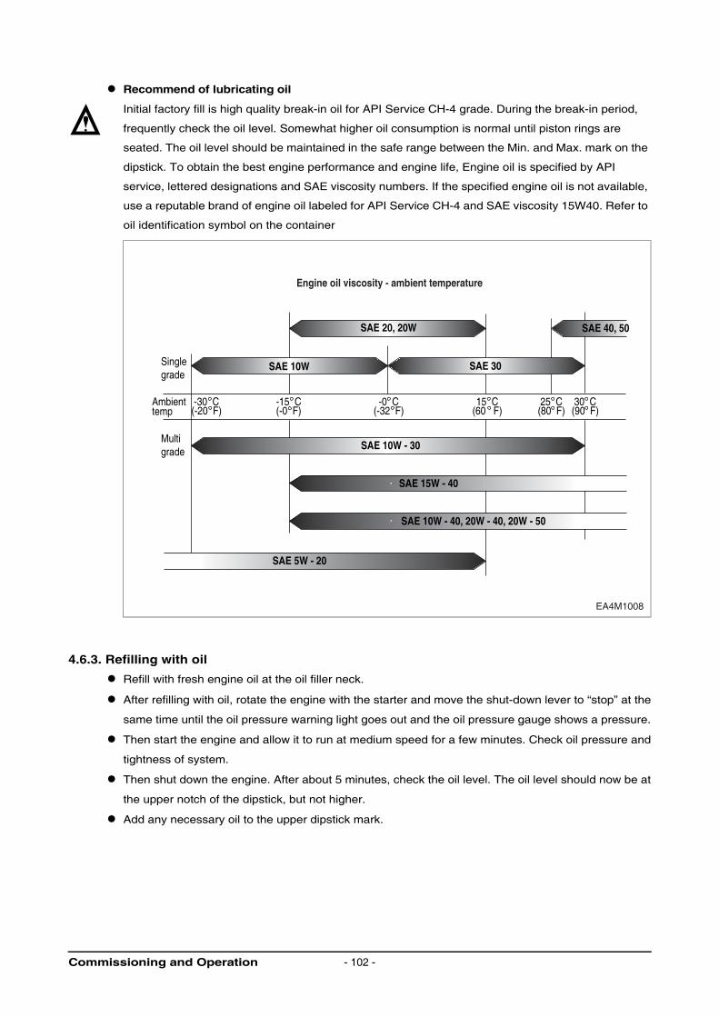
Recommend of lubricating oil
Initial factory fill is high quality break-in oil for API Service CH-4 grade. During the break-in period,
frequently check the oil level. Somewhat higher oil consumption is normal until piston rings are
seated. The oil level should be maintained in the safe range between the Min. and Max. mark on the
dipstick. To obtain the best engine performance and engine life, Engine oil is specified by API
service, lettered designations and SAE viscosity numbers. If the specified engine oil is not available,
use a reputable brand of engine oil labeled for API Service CH-4 and SAE viscosity 15W40. Refer to
oil identification symbol on the container
4.6.3. Refilling with oil
Refill with fresh engine oil at the oil filler neck.
After refilling with oil, rotate the engine with the starter and move the shut-down lever to “stop” at the
same time until the oil pressure warning light goes out and the oil pressure gauge shows a pressure.
Then start the engine and allow it to run at medium speed for a few minutes. Check oil pressure and
tightness of system.
Then shut down the engine. After about 5 minutes, check the oil level. The oil level should now be at
the upper notch of the dipstick, but not higher.
Add any necessary oil to the upper dipstick mark.
SAE 20, 20W
SAE 10W SAE 30
SAE 40, 50
SAE 10W - 30
SAE 5W - 20
SAE 15W - 40
SAE 10W - 40, 20W - 40, 20W - 50
-30 C
Singlegrade
Ambienttemp
Multigrade
(-20 F)-15 C(-0 F)
-0 C(-32 F)
15 C(60 F)
25 C(80 F)
30 C(90 F)
EA4M1008
Engine oil viscosity - ambient temperature
Commissioning and Operation - 102 -
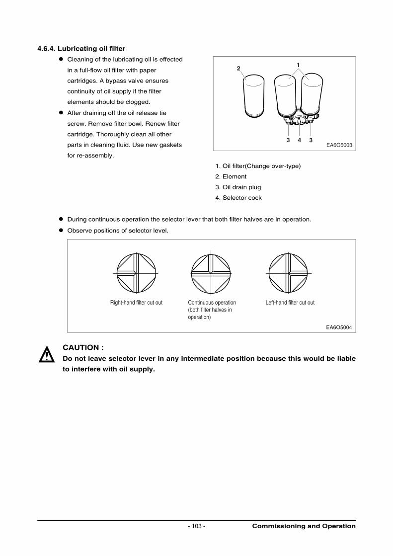
4.6.4. Lubricating oil filter
Cleaning of the lubricating oil is effected
in a full-flow oil filter with paper
cartridges. A bypass valve ensures
continuity of oil supply if the filter
elements should be clogged.
After draining off the oil release tie
screw. Remove filter bowl. Renew filter
cartridge. Thoroughly clean all other
parts in cleaning fluid. Use new gaskets
for re-assembly.
1. Oil filter(Change over-type)
2. Element
3. Oil drain plug
4. Selector cock
During continuous operation the selector lever that both filter halves are in operation.
Observe positions of selector level.
CAUTION :
Do not leave selector lever in any intermediate position because this would be liable
to interfere with oil supply.
EA6O5003
12
3 34
EA6O5004
Right-hand filter cut out Left-hand filter cut outContinuous operation(both filter halves inoperation)
Commissioning and Operation- 103 -

4.6.5. Renewal of filter cartridges
Allow the filter content to run off along drain plugs. Hold a suitable vessel under hole.
CAUTION :
Oil is hot and under pressure!
After releasing the clamping bolts remove filter bowls.
Renew filter cartridges. Thoroughly clean all other parts in cleaning fluid. (do not allow cleaning fluid
to enter the oil circuit)
NOTE :
To prevent the seal from twisting hold the filter bowl firmly when tightening the
tensioning screw.
Every time an oil change is made, the two oil filter cartridges should be renewed!
CAUTION :
Use oil filters are classed as dangerous waste and must be disposed of accordingly.
Commissioning and Operation - 104 -
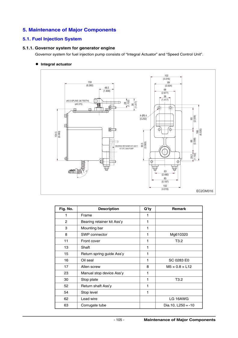
5. Maintenance of Major Components
5.1. Fuel Injection System
5.1.1. Governor system for generator engine
Governor system for fuel injection pump consists of “Integral Actuator” and “Speed Control Unit”.
Integral actuator
Fig. No. Description Q’ty Remark
1 Frame 1
2 Bearing retainer kit Ass’y 1
3 Mounting bar 1
8 SWP connector 1 Mg610320
11 Front cover 1 T3.2
13 Shaft 1
15 Return spring guide Ass’y 1
16 Oil seal 1 SC 0283 E0
17 Allen screw 8 M5 × 0.8 × L12
23 Manual stop device Ass’y 1
30 Stop plate 1 T3.2
52 Return shaft Ass’y 1
54 Stop level 1
62 Lead wire LG 16AWG
63 Corrugate tube Dia.10, L250 + -10
EC2OM316
48.5(1.909) 68
(2.677)
89(3.504)
102(4.016)
36(1.417)
63(2.480)
85(0.197)
102(4.016)
28(1
.102
)
36(1
.417
)
154.
5(6
.083
)
90.5
(3.5
63) 66
(2.5
98)
29.2
(1.1
50)
65(2
.559
)16
6(6
.535
)
159(6.260)
4- 6.4(0.252)
BEARING RETAINER KIT ASS’Y
KT 275, 3000 PUMP
9.5 SPLINE (36 TEETH)( 0.375)
Maintenance of Major Components- 105 -
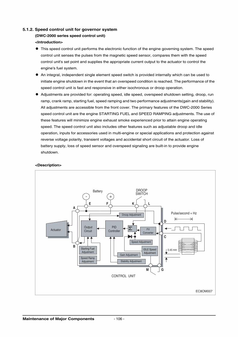
5.1.2. Speed control unit for governor system
(DWC-2000 series speed control unit)
<Introduction>
This speed control unit performs the electronic function of the engine governing system. The speed
control unit senses the pulses from the magnetic speed sensor, compares them with the speed
control unit's set point and supplies the appropriate current output to the actuator to control the
engine's fuel system.
An integral, independent single element speed switch is provided internally which can be used to
initiate engine shutdown in the event that an overspeed condition is reached. The performance of the
speed control unit is fast and responsive in either isochronous or droop operation.
Adjustments are provided for: operating speed, idle speed, overspeed shutdown setting, droop, run
ramp, crank ramp, starting fuel, speed ramping and two performance adjustments(gain and stability).
All adjustments are accessible from the front cover. The primary features of the DWC-2000 Series
speed control unit are the engine STARTING FUEL and SPEED RAMPING adjustments. The use of
these features will minimize engine exhaust smoke experienced prior to attain engine operating
speed. The speed control unit also includes other features such as adjustable droop and idle
operation, inputs for accessories used in multi-engine or special applications and protection against
reverse voltage polarity, transient voltages and accidental short circuit of the actuator. Loss of
battery supply, loss of speed sensor and overspeed signaling are built-in to provide engine
shutdown.
<Description>
EC8OM007
CONTROL UNIT
- +
OutputCircuitActuator
Battery DROOPSWITCH
Pulse/second = Hz
0.45 mm
M G
B
AE F K L
D
C
PIDController
Droop Adjustment
Speed Adjustment
Stability Adjustment
Gain Adjustment
Starting FuelAdjustment
IDLE SpeedAdjustment
FVConverter
Speed RampAdjustment
Maintenance of Major Components - 106 -
The engine speed signal is usually obtained from a magnetic speed sensor mounted in close
proximity to the teeth of a ferrous ring gear that is driven by the engine. The frequency of the speed
sensor signal is proportional to the engine speed. The speed control unit will accept any signal if the
frequency is proportional to engine signal, and in the frequency range of the speed control unit (1 K to
7.5 K Hz.). The speed sensor is typically mounted in close proximity to an engine driven ferrous gear,
usually the engine ring gear. As the teeth of the gear pass the magnetic sensor, a signal is generated
which is proportional to engine speed. The signal strength must also be within the range of the input
amplifier. An amplitude of 1 to 120 volts RMS is required to allow the unit to function within its design
specifications. The speed control unit has an input impedance of 20 K-ohms between the speed
sensor input terminals. (“C” & “D”). Terminal “D” is connected internally to the battery negative. Only
one end of the shielded cable should be connected.
When a speed sensor signal is received by the controller, the signal is amplified and shaped by an
internal circuit to form constant area pulses. If the speed sensor monitor does not detect a speed
sensor signal, the output circuit of the speed control unit will turn off all current to the actuator.
The summing point of the speed sensor and the speed adjust control is the input to the dynamic
control section of the governor. The dynamic control circuit, of which the gain and stability
adjustments are part, has a control function that will provide isochronous and stable performance for
most engine types and fuel systems.
The speed control unit circuit is influenced by the gain and stability performance adjustments. The
governor system sensitivity is increased with clockwise rotation of the gain adjustment. The gain
adjustment has a non-linear range of 33:1. The stability adjustment, when advanced clockwise,
increases the time rate of response of the governor system to match the various time constants of a
wide variety of engines. The speed control unit is a PID device, the “D”, derivative portion can be
varied when required.(See Instability section.)
During the engine cranking cycle, STARTING FUEL can be adjusted from an almost closed, to a
nearly full fuel position. Once the engine has started, the speed control point is determined, first by
the IDLE speed set point and the SPEED RAMPING circuit, After engine speed ramp- ing has been
completed, the engine will be at its governed operating speed. At the desired governed engine
speed, the actuator will be energized with sufficient current to maintain the desired engine speed,
independent of load (isochronous operation).
The output actuator current switching circuit provides current to drive the actuator. The output
transistor is alternately switched off and on at a frequency of 300 Hz. which is well beyond the natural
frequency of the actuator, hence no visible motion from the switching results. Switching the output
transistors reduces its internal power dissipation for efficient power control. The output circuit can
provide current of up to 10 amps continuous at 25 C for 24 VDC battery systems. The actuator
responds to the average current to position the engine fuel control lever.
In standard operation, the speed control unit performance is isochronous. Droop governing can be
selected by connecting terminals K & L and the percent of droop governing can be varied with the
droop adjustment control. The droop range can be decreased by connecting Terminals G and H.
The speed control unit has several performance and protection features which enhance the governor
system. A speed anticipation circuit minimizes speed overshoot on engine startup or when large
increments of load are applied to the engine.
Maintenance of Major Components- 107 -
5.1.3. Specification
Performance
Isochronous operation / steady state stability ......................................................... ± 0.25 % or better
Speed range / governor ............................................................................. 1 K ~ 7.5 K Hz continuous
Speed drift with temperature ................................................................................... ± 0.5 % maximum
Idle adjust CW ........................................................................................................ 60 % of set speed
Idle adjust CCW .................................................................................................... less than 1,200 Hz
Droop range .............................................................................................................1-5 % regulation *
Droop adjust max. (K-L jumpered) ................................................ 450 Hz, ± 90 Hz per 1.0 A change
Droop adjust min. (K-L Jumpered) .................................................... 20 Hz, ± 8 Hz per 1.0 A change
Speed trim range................................................................................................................... ± 210 Hz
Remote variable speed range .......................................................... 500 ~ 7.5 Hz or any part thereof
Terminal sensitivity
J................................................................................100 Hz ± 15 Hz / Volt @ 6.0 K impendence
L ............................................................................... 680 Hz ± 50 Hz/Volt @ 165 K impendence
N.................................................................................135 Hz ± 10 Hz/Volt @ 1 MΩ impendence
P .................................................................................................10 VCD supply @ 20 [mA] max.
Environmental
Ambient operating temperature range ............................................................................... -40 ~ 85 °C
Relative humidity ................................................................................................................. up to 95%
All surface finishes ..................................................................... fungus proof and corrosion resistant
Power input
Supply ....................................... 24 VDC battery system (transient and reverse voltage protected)**
Polarity ............................................................................................... negative ground (case isolated)
Power consumption ............................................................ 50 [mA] continuous plus actuator current
Maximum controllable actuator current at 25 °C- (Inductive Load) ....................... 10A continuous***
Magnetic speed sensor signal ....................................................................................1 ~ 120[V] RMS
Reliability
Vibration ................................................................................................................. 1G @ 20 ~ 100 Hz
Testing ......................................................................................................... 100 % functionally tested
Physical
Dimensions ........................................................................................................... see outline (dia. 1)
Weight ................................................................................................................................ 705 grams
Mounting .............................................................................................. any position, vertical preferred
* Droop is based on a speed sensor frequency of 4,000 Hz. and an actuator current change of 1 amp
from no load to full load. Applications with higher speed sensor signals will experience less
percentage of droop. See droop description for specific details on operation of droop ranges.
** Protected against reverse voltage by a series diode. A 15 amp fuse must be installed in the positive
battery lead.
*** Protected against short circuit to actuator (shuts off current to actuator), unit automatically turns
back on when short is removed.
Maintenance of Major Components - 108 -
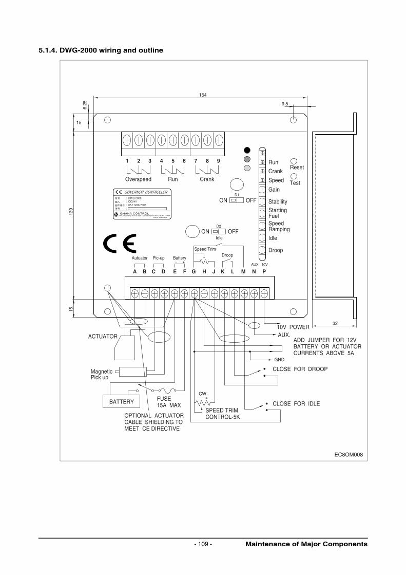
5.1.4. DWG-2000 wiring and outline
154
9.5
6.25
15
139
15
1 2 3 4 5 6
A B C D E F G H J K L M N P
7 8 9
: DWC-2000: DC24V: 65.11220-7006:
826-1 Kuro 3-Dong, Duro-Gu Seoul 152-053 KOREA(DONG-IL TECKNO-TOWN)
Overspeed
ACTUATOR
MagneticPick up
BATTERY
OPTIONAL ACTUATORCABLE SHIELDING TOMEET CE DIRECTIVE
ADD JUMPER FOR 12VBATTERY OR ACTUATORCURRENTS ABOVE 5A
AUX.10V POWER
FUSE15A MAX
SPEED TRIMCONTROL-5K
CLOSE FOR IDLE
CLOSE FOR DROOP
Run Crank
Reset
StartingFuelSpeedRamping
Run
Crank
Speed
Gain
Stability
Idle
Droop
Test
ON OFF
ON
Autuator Pic-up Battery
Idle
Speed TrimDroop
OFF
GHANA CONTROLMADE IN KOREA
D1
D2
- +AUX 10V
32
CW
GND
EC8OM008
Maintenance of Major Components- 109 -
5.1.5. Application and installation information
The speed control unit is rugged enough for mounting in a control cabinet or engine mounted
enclosure or in a remote console up to 20 meters(65 ft.) from the engine. Care should be taken to
insure that the speed control unit, mount it vertically so that condensation will not accumulate in the
speed control unit.
WARNING :
An overspeed shutdown device, independent of the governor system, should be
provided to prevent loss of engine control which may cause personal injury or
equipment damage. Do not rely exclusively on the governor system electric actuator
to prevent over speed. A Secondary shutoff device, such as a fuel solenoid must be
used.
5.1.6. Wiring
Wiring to the speed control unit should be as shown in Diagram 1. Wire leads to the battery and
actuator from the speed control unit terminals A, B, E and F should be #16 AWG(1.3 mm sq.) or
larger. Long cables require an increased wire size to minimize voltage drops. An external 15 amp
fuse is recommended in series with terminal F, the positive (+) battery input terminal.
The magnetic speed sensor leads must be twisted and/or shielded for their entire length. If shielded
cables are used, connect all the shields to terminal D only. The shield should be insulated to insure
no other part of the shield comes in contact with engine ground, otherwise stray speed signals may
be introduced to the speed control unit. With the engine stopped, adjust the gap between the
magnetic speed sensor and the ring gear teeth. The gap should not be any smaller than 0.020 in
(0.45 mm). Usually, gear tooth will achieve a satisfactory air gap. The magnetic speed sensor
voltage should be at least 1 VAC RMS during cranking.
5.1.7. Adjustments
Before starting engine
Confirm the following adjustment positions. The adjustments are factory pre-set as follows :
Check to insure the GAIN and STABILITY adjustments, and if applied, the external SPEED TRIM
CONTROL are set to mid position.
Preset the DWC-2000 as follows :
Gain.............................................................................................................................Minimum CCW
Stability................................................................................................................................Mid-range
Speed adjust ........................................................................................................................ 3,650 Hz
Idle ........................................................................................................................................1,950 Hz
Droop ........................................................................................... Maximum CCW (Minimum setting)
Over speed .................................................................................................................. Maximum CW
Run ramp ..................................................................................................................... Maximum CW
Crank ramp .................................................................................................................. Maximum CW
Starting fuel .................................................................................................. Full CW (Maximum fuel)
Speed ramping.................................................................................................... Full CCW (Fastest )
Maintenance of Major Components - 110 -
Start engine
The speed control unit governed speed setting is factory set at approximately engine idle speed.
Crank the engine with DC power applied to the governor system. The actuator will energize to the
maximum fuel position until the engine starts. The governor system should control the engine at a
low idle speed. If the engine is unstable after starting, turn the GAIN and STABILITY adjustments
counterclockwise until the engine is stable.
Governor speed setting
The governed speed set point is increased by clockwise rotation of the SPEED adjustment control.
Remote speed adjustment can be obtained with an optional 5 K Speed Trim Control.
(See Diagram 1.)
Governor performance
Once the engine is at operating speed and at no load, the following governor performance
adjustment can be made.
(1) At no load, turn the gain control CW until instability results. Then back-off slightly CCW (1/8 turn)
beyond the point where stability returns.
(2) Turn the stability control CW until instability results. Then back-off slightly CCW (1/8 turn)
beyond the point where stability returns. Excellent performance should result from these
adjustments.
If instability cannot be corrected or further performance improvements are required, refer to the
section on SYSTEM TROUBLESHOOTING.
Starting fuel adjustment
The engine’s exhaust smoke at start-up can be minimized by completing the following adjustments.
(1) Place the engine in idle by connecting Terminals M & G.
(2) Adjust the IDLE speed for as low a speed setting as the application allows.
(3) Adjust the STARTING FUEL CCW until the engine speed begins to fall. Increase the STARTING
FUEL slightly so that the idle speed is returned to the desired level.
(4) Stop the engine
Maintenance of Major Components- 111 -
One of two methods of operation for the DWC-2000 may now be selected
Method 1 : Start the engine and accelerate directly to the operating speed(Gen Sets, etc.).
Remove the connection between Terminals M & G. Start the engine and adjust the
SPEED RAMPING for the least smoke on acceleration from idle to rated speed. If the
starting smoke is excessive, the STARTING FUEL may need to be adjusted slightly
CCW. If the starting time is too long, the STARTING FUEL may need to be adjusted
slightly CW
Method 2 : Start the engine and control at an idle speed for a period of time prior to accelerating to
the operating speed. This method separates the starting process so that each may be
optimized for the lowest smoke emissions.
Replace the connection between Terminals M & G with a switch, usually an oil pressure
switch. Start the engine. If the starting smoke is excessive, the STARTING FUEL may
need to be adjusted slightly CCW. If the starting time is too long, the STARTING FUEL
may need to be adjusted slightly CW.
When the switch opens, adjust the SPEED RAMPING for the least amount of smoke
when accelerating from idle speed to rated speed.
Idle speed setting
If the IDLE speed setting was not adjusted as detailed in “Starting Fuel Adjustment” section, then
place the optional external selector switch in the IDLE position. The idle speed set point is increased
by clockwise rotation of the IDLE adjustment control. When the engine is at idle speed, the speed
control unit applies droop to the governor system to insure stable operation.
Speed droop operation
Droop is typically used for the paralleling
of engine driven generators.
Place the optional external selector
switch in the DROOP position, DROOP
is increased by clockwise rotation of the
DROOP adjustment control. When in
droop operation, the engine speed will
decrease as engine load increases.
The percentage of droop is based on the
actuator current change from engine no
load to full load. A wide range of droop is
available with the internal control. Droop
level requirements above 10 % are
unusual.
If droop levels experienced are higher or lower than those required, contact the factory for
assistance.
After the droop level has been adjusted, the rated engine speed setting may need to be reset. Check
the engine speed and adjust the speed setting accordingly.
EC8OM009
SPEED
TIME
Set speed
No load Load up
Full load
Adjust the DROOP adjustment
DROOP width(Below 10% of the set-speed)
Maintenance of Major Components - 112 -
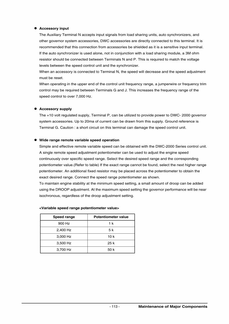
Accessory input
The Auxiliary Terminal N accepts input signals from load sharing units, auto synchronizers, and
other governor system accessories, DWC accessories are directly connected to this terminal. It is
recommended that this connection from accessories be shielded as it is a sensitive input terminal.
If the auto synchronizer is used alone, not in conjunction with a load sharing module, a 3M ohm
resistor should be connected between Terminals N and P. This is required to match the voltage
levels between the speed control unit and the synchronizer.
When an accessory is connected to Terminal N, the speed will decrease and the speed adjustment
must be reset.
When operating in the upper end of the control unit frequency range, a jumperwire or frequency trim
control may be required between Terminals G and J. This increases the frequency range of the
speed control to over 7,000 Hz.
Accessory supply
The +10 volt regulated supply, Terminal P, can be utilized to provide power to DWC- 2000 governor
system accessories. Up to 20ma of current can be drawn from this supply. Ground reference is
Terminal G. Caution : a short circuit on this terminal can damage the speed control unit.
Wide range remote variable speed operation
Simple and effective remote variable speed can be obtained with the DWC-2000 Series control unit.
A single remote speed adjustment potentiometer can be used to adjust the engine speed
continuously over specific speed range. Select the desired speed range and the corresponding
potentiometer value.(Refer to table) If the exact range cannot be found, select the next higher range
potentiometer. An additional fixed resistor may be placed across the potentiometer to obtain the
exact desired range. Connect the speed range potentiometer as shown.
To maintain engine stability at the minimum speed setting, a small amount of droop can be added
using the DROOP adjustment. At the maximum speed setting the governor performance will be near
isochronous, regardless of the droop adjustment setting.
<Variable speed range potentiometer value>
Speed range Potentiometer value
900 Hz 1 k
2,400 Hz 5 k
3,000 Hz 10 k
3,500 Hz 25 k
3,700 Hz 50 k
Maintenance of Major Components- 113 -
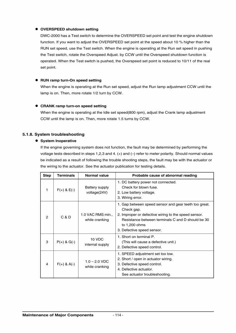
OVERSPEED shutdown setting
DWC-2000 has a Test switch to determine the OVERSPEED set point and test the engine shutdown
function. If you want to adjust the OVERSPEED set point at the speed about 10 % higher than the
RUN set speed, use the Test switch. When the engine is operating at the Run set speed in pushing
the Test switch, rotate the Overspeed Adjust. by CCW until the Overspeed shutdown function is
operated. When the Test switch is pushed, the Overspeed set point is reduced to 10/11 of the real
set point.
RUN ramp turn-On speed setting
When the engine is operating at the Run set speed, adjust the Run lamp adjustment CCW until the
lamp is on. Then, more rotate 1/2 turn by CCW.
CRANK ramp turn-on speed setting
When the engine is operating at the Idle set speed(800 rpm), adjust the Crank lamp adjustment
CCW until the lamp is on. Then, more rotate 1.5 turns by CCW.
5.1.8. System troubleshooting
System Inoperative
If the engine governing system does not function, the fault may be determined by performing the
voltage tests described in steps 1,2,3 and 4. (+) and (–) refer to meter polarity. Should normal values
be indicated as a result of following the trouble shooting steps, the fault may be with the actuator or
the wiring to the actuator. See the actuator publication for testing details.
Step Terminals Normal value Probable cause of abnormal reading
1 F(+) & E(-)Battery supply voltage(24V)
1. DC battery power not connected.
Check for blown fuse.2. Low battery voltage.
3. Wiring error.
2 C & D1.0 VAC RMS min.,
while cranking
1. Gap between speed sensor and gear teeth too great.
Check gap.
2. Improper or defective wiring to the speed sensor. Resistance between terminals C and D should be 30
to 1,200 ohms
3. Defective speed sensor.
3 P(+) & G(-)10 VDC
internal supply
1. Short on terminal P.
(This will cause a defective unit.)2. Defective speed control.
4 F(+) & A(-)1.0 – 2.0 VDCwhile cranking
1. SPEED adjustment set too low.2. Short / open in actuator wiring.
3. Defective speed control.
4. Defective actuator.See actuator troubleshooting.
Maintenance of Major Components - 114 -
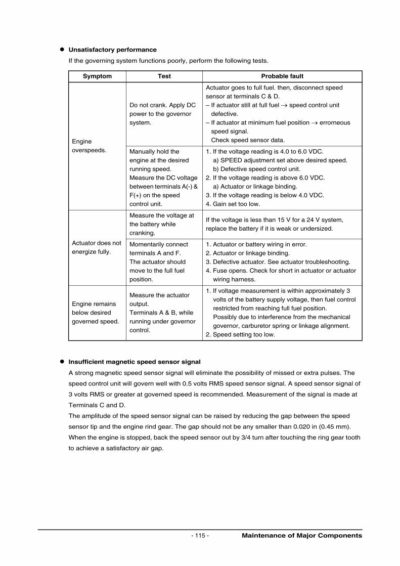
Unsatisfactory performance
If the governing system functions poorly, perform the following tests.
Insufficient magnetic speed sensor signal
A strong magnetic speed sensor signal will eliminate the possibility of missed or extra pulses. The
speed control unit will govern well with 0.5 volts RMS speed sensor signal. A speed sensor signal of
3 volts RMS or greater at governed speed is recommended. Measurement of the signal is made at
Terminals C and D.
The amplitude of the speed sensor signal can be raised by reducing the gap between the speed
sensor tip and the engine rind gear. The gap should not be any smaller than 0.020 in (0.45 mm).
When the engine is stopped, back the speed sensor out by 3/4 turn after touching the ring gear tooth
to achieve a satisfactory air gap.
Symptom Test Probable fault
Engine
overspeeds.
Do not crank. Apply DC
power to the governor system.
Actuator goes to full fuel. then, disconnect speed sensor at terminals C & D.
– If actuator still at full fuel → speed control unit
defective.– If actuator at minimum fuel position → errorneous
speed signal.
Check speed sensor data.
Manually hold the
engine at the desired running speed.
Measure the DC voltage
between terminals A(-) & F(+) on the speed
control unit.
1. If the voltage reading is 4.0 to 6.0 VDC.
a) SPEED adjustment set above desired speed.b) Defective speed control unit.
2. If the voltage reading is above 6.0 VDC.
a) Actuator or linkage binding.3. If the voltage reading is below 4.0 VDC.
4. Gain set too low.
Actuator does not energize fully.
Measure the voltage at
the battery while
cranking.
If the voltage is less than 15 V for a 24 V system,replace the battery if it is weak or undersized.
Momentarily connect
terminals A and F.
The actuator should move to the full fuel
position.
1. Actuator or battery wiring in error.
2. Actuator or linkage binding.
3. Defective actuator. See actuator troubleshooting.4. Fuse opens. Check for short in actuator or actuator
wiring harness.
Engine remains
below desired
governed speed.
Measure the actuator output.
Terminals A & B, while
running under governor control.
1. If voltage measurement is within approximately 3
volts of the battery supply voltage, then fuel control
restricted from reaching full fuel position.Possibly due to interference from the mechanical
governor, carburetor spring or linkage alignment.
2. Speed setting too low.
Maintenance of Major Components- 115 -
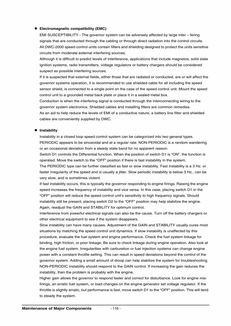
Electromagnetic compatibility (EMC)
EMI SUSCEPTIBILITY - The governor system can be adversely affected by large inter – fering
signals that are conducted through the cabling or through direct radiation into the control circuits.
All DWC-2000 speed control units contain filters and shielding designed to protect the units sensitive
circuits from moderate external interfering sources.
Although it is difficult to predict levels of interference, applications that include magnetos, solid state
ignition systems, radio transmitters, voltage regulators or battery chargers should be considered
suspect as possible interfering sources.
If it is suspected that external fields, either those that are radiated or conducted, are or will affect the
governor systems operation, it is recommended to use shielded cable for all including the speed
sensor shield, is connected to a single point on the case of the speed control unit. Mount the speed
control unit to a grounded metal back plate or place it in a sealed metal box.
Conduction is when the interfering signal is conducted through the interconnecting wiring to the
governor system electronics. Shielded cables and installing filters are common remedies.
As an aid to help reduce the levels of EMI of a conductive nature, a battery line filter and shielded
cables are conveniently supplied by DWC.
Instability
Instability in a closed loop speed control system can be categorized into two general types.
PERIODIC appears to be sinusoidal and at a regular rate. NON-PERIODIC is a random wandering
or an occasional deviation from a steady state band for no apparent reason.
Switch D1 controls the Differential function. When the position of switch D1 is “ON”, the function is
operated. Move the switch to the “OFF” position if there is fast instability in the system.
The PERIODIC type can be further classified as fast or slow instability. Fast instability is a 3 Hz. or
faster irregularity of the speed and is usually a jitter. Slow periodic instability is below 3 Hz., can be
very slow, and is sometimes violent.
If fast instability occurs, this is typically the governor responding to engine firings. Raising the engine
speed increases the frequency of instability and vice versa. In this case, placing switch D1 in the
“OFF” position will reduce the speed control unit’s sensitivity to high frequency signals. Should
instability still be present, placing switch D2 to the “OFF” position may help stabilize the engine.
Again, readjust the GAIN and STABILITY for optimum control.
Interference from powerful electrical signals can also be the cause. Turn off the battery chargers or
other electrical equipment to see if the system disappears.
Slow instability can have many causes. Adjustment of the GAIN and STABILITY usually cures most
situations by matching the speed control unit dynamics. If slow instability is unaffected by this
procedure, evaluate the fuel system and engine performance. Check the fuel system linkage for
binding, high friction, or poor linkage. Be sure to check linkage during engine operation. Also look at
the engine fuel system. Irregularities with carburetion or fuel injection systems can change engine
power with a constant throttle setting. This can result in speed deviations beyond the control of the
governor system. Adding a small amount of droop can help stabilize the system for troubleshooting.
NON-PERIODIC instability should respond to the GAIN control. If increasing the gain reduces the
instability, then the problem is probably with the engine.
Higher gain allows the governor to respond faster and correct for disturbance. Look for engine mis-
firings, an erratic fuel system, or load changes on the engine generator set voltage regulator. If the
throttle is slightly erratic, but performance is fast, move switch D1 to the “OFF” position. This will tend
to steady the system.
Maintenance of Major Components - 116 -
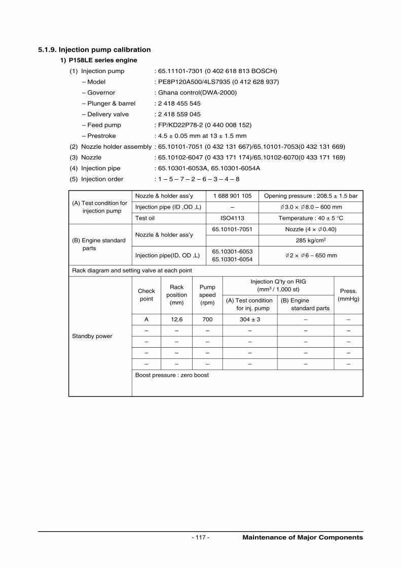
5.1.9. Injection pump calibration
1) P158LE series engine
(1) Injection pump : 65.11101-7301 (0 402 618 813 BOSCH)
– Model : PE8P120A500/4LS7935 (0 412 628 937)
– Governor : Ghana control(DWA-2000)
– Plunger & barrel : 2 418 455 545
– Delivery valve : 2 418 559 045
– Feed pump : FP/KD22P78-2 (0 440 008 152)
– Prestroke : 4.5 ± 0.05 mm at 13 ± 1.5 mm
(2) Nozzle holder assembly : 65.10101-7051 (0 432 131 667)/65.10101-7053(0 432 131 669)
(3) Nozzle : 65.10102-6047 (0 433 171 174)/65.10102-6070(0 433 171 169)
(4) Injection pipe : 65.10301-6053A, 65.10301-6054A
(5) Injection order : 1 – 5 – 7 – 2 – 6 – 3 – 4 – 8
(A) Test condition for injection pump
Nozzle & holder ass’y 1 688 901 105 Opening pressure : 208.5 ± 1.5 bar
Injection pipe (ID ,OD ,L) – 3.0 × 8.0 – 600 mm
Test oil ISO4113 Temperature : 40 ± 5 °C
(B) Engine standard parts
Nozzle & holder ass’y65.10101-7051 Nozzle (4 × 0.40)
285 kg/cm2
Injection pipe(ID, OD ,L)65.10301-605365.10301-6054
2 × 6 – 650 mm
Rack diagram and setting valve at each point
Standby power
Checkpoint
Rackposition (mm)
Pump speed(rpm)
Injection Q’ty on RIG(mm3 / 1,000 st) Press.
(mmHg)(A) Test condition for inj. pump
(B) Engine standard parts
A 12.6 700 304 ± 3 – –
– – – – – –
– – – – – –
– – – – – –
– – – – – –
Boost pressure : zero boost
Maintenance of Major Components- 117 -
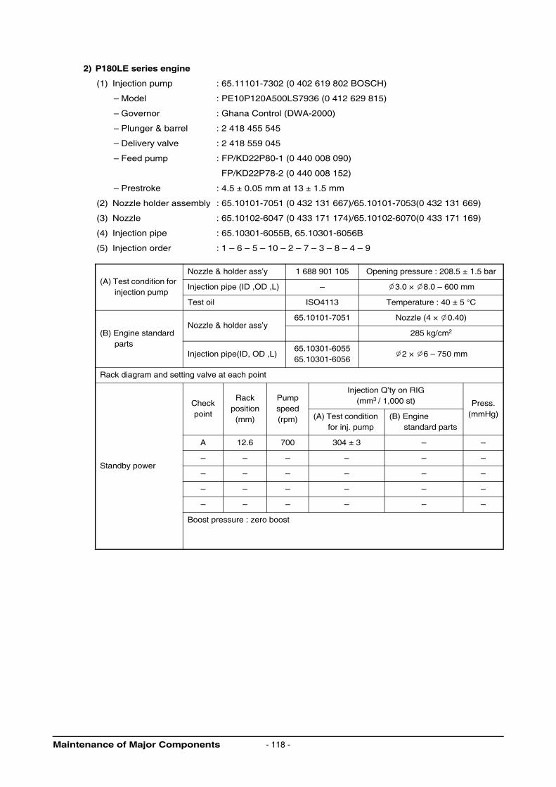
2) P180LE series engine
(1) Injection pump : 65.11101-7302 (0 402 619 802 BOSCH)
– Model : PE10P120A500LS7936 (0 412 629 815)
– Governor : Ghana Control (DWA-2000)
– Plunger & barrel : 2 418 455 545
– Delivery valve : 2 418 559 045
– Feed pump : FP/KD22P80-1 (0 440 008 090)
FP/KD22P78-2 (0 440 008 152)
– Prestroke : 4.5 ± 0.05 mm at 13 ± 1.5 mm
(2) Nozzle holder assembly : 65.10101-7051 (0 432 131 667)/65.10101-7053(0 432 131 669)
(3) Nozzle : 65.10102-6047 (0 433 171 174)/65.10102-6070(0 433 171 169)
(4) Injection pipe : 65.10301-6055B, 65.10301-6056B
(5) Injection order : 1 – 6 – 5 – 10 – 2 – 7 – 3 – 8 – 4 – 9
(A) Test condition for injection pump
Nozzle & holder ass’y 1 688 901 105 Opening pressure : 208.5 ± 1.5 bar
Injection pipe (ID ,OD ,L) – 3.0 × 8.0 – 600 mm
Test oil ISO4113 Temperature : 40 ± 5 °C
(B) Engine standard parts
Nozzle & holder ass’y65.10101-7051 Nozzle (4 × 0.40)
285 kg/cm2
Injection pipe(ID, OD ,L)65.10301-605565.10301-6056
2 × 6 – 750 mm
Rack diagram and setting valve at each point
Standby power
Checkpoint
Rackposition (mm)
Pump speed(rpm)
Injection Q’ty on RIG(mm3 / 1,000 st) Press.
(mmHg)(A) Test condition for inj. pump
(B) Engine standard parts
A 12.6 700 304 ± 3 – –
– – – – – –
– – – – – –
– – – – – –
– – – – – –
Boost pressure : zero boost
Maintenance of Major Components - 118 -

3) P222LE series engine
(1) Injection pump : 65.11101-7303 (0 402 610 807 BOSCH)
– Model : PE12P120A500LS7937 (0 412 620 854)
– Governor : Ghana control(DWA-2000)
– Plunger & barrel : 2 418 455 545
– Delivery valve : 2 418 559 045
– Feed pump : FP/KD22P80-1 (0 440 008 090)
FP/KD22P78-2 (0 440 008 152)
– Prestroke : 4.5 ± 0.05 mm at 13 ± 1.5 mm
(2) Nozzle holder assembly : 65.10101-7051 (0 432 131 667)/65.10101-7053(0 432 131 669)
(3) Nozzle : 65.10102-6047 (0 433 171 174)/65.10102-6070(0 433 171 169)
(4) Injection pipe : 65.10301-6113, 65.10301-6114A
(5) Injection order : 1 – 12 – 5 – 8 – 3 – 10 – 6 – 7 – 2 – 11 – 4 – 9
(A) Test condition for injection pump
Nozzle & holder ass’y 1 688 901 105 Opening pressure : 208.5 ± 1.5 bar
Injection pipe (ID ,OD ,L) – 3.0 × 8.0 – 600 mm
Test oil ISO4113 Temperature : 40 ± 5 °C
(B) Engine standard parts
Nozzle & holder ass’y65.10101-7051 Nozzle (5 × 0.26)
285 kg/cm2
Injection pipe(ID, OD ,L)65.10301-605765.10301-6058
2 × 6 – 750 mm
Rack diagram and setting valve at each point
Standby power
Checkpoint
Rackposition (mm)
Pump speed(rpm)
Injection Q’ty on RIG(mm3 / 1,000 st) Press.
(mmHg)(A) Test condition for inj. pump
(B) Engine standard parts
A 12.6 700 304 ± 3 – –
– – – – – –
– – – – – –
– – – – – –
– – – – – –
Boost pressure : zero boost
Maintenance of Major Components- 119 -

4) PU158TI engine
(1) Injection pump : 65.11101-7680 (A 401 881 102 BOSCH)
– Model : PE8P120A520/4LS7947 (0 412 628 942)
– Governor : RQV250…900PA1434(0 440 008 152)
– Plunger & barrel : 2 418 455 188
– Delivery valve : 2 418 552 039
– Feed pump : FP/KD22P78-2 (0 440 008 152)
– Prestroke : 4.5 ± 0.05 mm
(2) Nozzle holder assembly : 65.10101-7053 (0 432 131 669)
(3) Nozzle : 65.10102-6070 (0 433 171 169)
(4) Injection pipe : 65.10301-6053A, 65.10301-6054A
(5) Injection order : 1 – 5 – 7 – 2 – 6 – 3 – 4 – 8
(A) Test condition for injection pump
Nozzle & Holder Ass’y 1 688 901 019 Opening pressure : 212.6 bar
Injection pipe(OD ,ID ,L) 1 680 750 075 8.0 x 3.0 – 1,000 mm
Test oil ISO4113 Temperature :40 ± 2 °C
(B) Engine standard partsNozzle & holder Ass’y
65.10101-7053 Nozzle (5 x 0.418)
0 432 131 669 Spec. : 285.5 bar
Injection pipe (OD, ID, L) 6 x 2 – 750 mm
Rack diagram and setting valve at each point
Refer to (3) Rack Diagram
CheckPoint
Rackposition(mm)
PumpSpeed(rpm)
Injection Q’ty on RIG(mm3 / 1,000st) Press.
(mmHg)(A) Test condition for inj. Pump
(B) Engine standard parts
V1 12.00 ± 0.05 1,050 266.0 ± 3.0 Max. power 1,500
V2 12.00 ± 0.10 800 266.0 ± 3.0 – 1,500
VS 8.96 ± 0.20 500 159.8 ± 1.0 – 0
LQ 6.15 ± 0.20 350 53.7 ± 15.0 Only 2/3/4/8 0
A3 7.10 ± 0.50 1,150 109.4 ± 15.0 Only 2/3/4/8 0
ST with Cap 100 127.5 ± 10.0 Only 2/3/4/8 0
Boost pressure dependent full –load stop (boost compensator spring operation point)
Refer to(4) Boost pressure
Checkpoint
Rack Position
(mm)
Pumpspeed(rpm)
Injection Q’ty on RIG(mm3 / 1,000st) Press.
(mmHg)(A) Test condition for inj. Pump
(B) Engine standard parts
P1 12.00 ± 0.05 500 – – 1,500
P2 8.96 ± 0.05 500 – – 0
P3 9.25 ± 0.10 500 – – 275
P4 11.20 ± 0.05 500 – – 600
Weight Weight =630 g Lever ratio(min/max) Not fixed
Idle spring k=14.03 N/mm Plunger 12
Middle spring k=57.14 N/mm Delivery valve retraction volume 90 mm3/st
Inner spring k=21.98 N/mm Delivery valve opening pressure –
LDA spring k=30.5 N/mm Delivery valve spring k = 7.2 N/mm
Feed Pump Double action Timer None
Maintenance of Major Components - 120 -
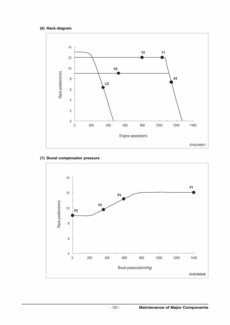
(6) Rack diagram
(7) Boost compensator pressure
EH5OM007
0
2
4
6
8
10
12
14
0 200 400 600 800 1000 1200 1400
A3
VS
LQ
V2 V1
Engine speed(rpm)
Rac
k po
sitio
n(m
m)
4
6
8
10
12
14
0 200 400 600 800 1000 1200 1400
Boost pressure(mmHg)
P1
P4
P3
P2
EH5OM008
Rac
k po
sitio
n(m
m)
Maintenance of Major Components- 121 -
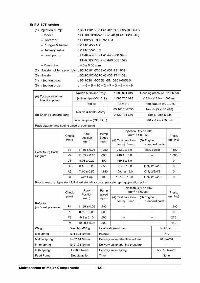
5) PU180TI engine
(1) Injection pump : 65.11101-7681 (A 401 890 895 BOSCH)
– Model : PE10P120A520LS7948 (0 412 629 816)
– Governor : RQV250…900PA1434
– Plunger & barrel : 2 418 455 188
– Delivery valve : 2 418 552 039
– Feed pump : FP/KD22P80-1 (0 440 008 090)
FP/KD22P78-2 (0 440 008 152)
– Prestroke : 4.5 ± 0.05 mm
(2) Nozzle holder assembly : 65.10101-7053 (0 432 131 669)
(3) Nozzle : 65.10102-6070 (0 433 171 169)
(4) Injection pipe : 65.10301-6055B, 65.10301-6056B
(5) Injection order : 1 – 6 – 5 – 10 – 2 – 7 – 3 – 8 – 4 - 9
(A) Test condition for injection pump
Nozzle & Holder Ass’y 1 688 901 019 Opening pressure : 212.6 bar
Injection pipe(OD ,ID ,L) 1 680 750 075 8.0 x 3.0 – 1,000 mm
Test oil ISO4113 Temperature :40 ± 2 °C
(B) Engine standard partsNozzle & holder Ass’y
65.10101-7053 Nozzle (5 x 0.418)
0 432 131 669 Spec. : 285.5 bar
Injection pipe (OD, ID, L) 6 x 2 – 750 mm
Rack diagram and setting valve at each point
Refer to (3) Rack Diagram
CheckPoint
Rackposition(mm)
PumpSpeed(rpm)
Injection Q’ty on RIG(mm3 / 1,000st) Press.
(mmHg)(A) Test condition for inj. Pump
(B) Engine standard parts
V1 11.55 ± 0.05 1,050 243.0 ± 3.0 Max. power 1,500
V2 11.55 ± 0.10 800 240.4 ± 3.0 – 1,500
VS 8.96 ± 0.20 500 159.8 ± 1.0 – 0
LQ 6.15 ± 0.20 350 53.7 ± 15.0 Only 2/3/4/8 0
A3 7.10 ± 0.50 1,150 109.4 ± 15.0 Only 2/3/4/8 0
ST with Cap 100 127.5 ± 10.0 Only 2/3/4/8 0
Boost pressure dependent full –load stop (boost compensator spring operation point)
Refer to(4) Boost pressure
Checkpoint
Rack Position
(mm)
Pumpspeed(rpm)
Injection Q’ty on RIG(mm3 / 1,000st) Press.
(mmHg)(A) Test condition for inj. Pump
(B) Engine standard parts
P1 11.55 ± 0.05 500 – – 1,500
P2 8.96 ± 0.05 500 – – 0
P3 9.9 ± 0.10 500 – – 275
P4 10.90 ± 0.05 500 – – 450
Weight Weight =630 g Lever ratio(min/max) Not fixed
Idle spring k=14.03 N/mm Plunger 12
Middle spring k=57.14 N/mm Delivery valve retraction volume 90 mm3/st
Inner spring k=21.98 N/mm Delivery valve opening pressure –
LDA spring k=30.5 N/mm Delivery valve spring k = 7.2 N/mm
Feed Pump Double action Timer None
Maintenance of Major Components - 122 -

(6) Rack diagram
(7) Boost compensator pressure
EH5OM009
Engine speed(rpm)
Rac
k po
sitio
n(m
m)
0
2
4
6
8
10
12
0 200 400 600 800 1000 1200 1400
V2 V1
VS
LQ
A3
Boost pressure(mmHg)
EH5OM010
Rac
k po
sitio
n(m
m)
4
6
8
10
12
0 200 400 600 800 1000 1200
P3
P1
P2
P4
Maintenance of Major Components- 123 -

6) PU222TI engine
(1) Injection pump : 65.11101-7319 (0 401 890 979E BOSCH)
– Model : PE12P120A520LS7972 (0 412 620 869)
– Governor : RQV250…900PA1434
– Plunger & barrel : 2 418 455 545
– Delivery valve : 2 418 559 045
– Feed pump : FP/KD22P78-1 (0 440 008 090)
FP/KD22P78-2 (0 440 008 152)
– Prestroke : 4.08 ± 0.05 mm
(2) Nozzle holder assembly : 65.10101-7053 (0 432 131 669)
(3) Nozzle : 65.10102-6070 (0 433 171 169)
(4) Injection pipe : 65.10301-6113, 65.10301-6114A
(5) Injection order : 1 – 12 – 5 – 8 – 3 – 10 – 6 – 7 – 2 – 11 – 4 – 9
(A) Test condition for injection pump
Nozzle & Holder Ass’y 1 688 901 019 Opening pressure : 212.6 bar
Injection pipe(OD ,ID ,L) 1 680 750 075 8.0 x 3.0 – 1,000 mm
Test oil ISO4113 Temperature :40 ± 2 °C
(B) Engine standard partsNozzle & holder Ass’y
65.10101-7053 Nozzle (5 x 0.418)
0 432 131 669 Spec. : 285.5 bar
Injection pipe (OD, ID, L) 6 x 2 – 750 mm
Rack diagram and setting valve at each point
Refer to (3) Rack Diagram
CheckPoint
Rackposition(mm)
PumpSpeed(rpm)
Injection Q’ty on RIG(mm3 / 1,000st) Press.
(mmHg)(A) Test condition for inj. Pump
(B) Engine standard parts
V1 12.00 ± 0.05 1,050 266.0 ± 3.0 Max. power 1,500
V2 12.00 ± 0.10 800 266.0 ± 3.0 – 1,500
VS 8.96 ± 0.20 500 159.8 ± 1.0 – 0
LQ 6.15 ± 0.20 350 53.7 ± 15.0 Only 2/3/4/8 0
A3 7.10 ± 0.50 1,150 109.4 ± 15.0 Only 2/3/4/8 0
ST with Cap 100 127.5 ± 10.0 Only 2/3/4/8 0
Boost pressure dependent full –load stop (boost compensator spring operation point)
Refer to(4) Boost pressure
Checkpoint
Rack Position
(mm)
Pumpspeed(rpm)
Injection Q’ty on RIG(mm3 / 1,000st) Press.
(mmHg)(A) Test condition for inj. Pump
(B) Engine standard parts
P1 12.00 ± 0.05 500 – – 1,500
P2 8.96 ± 0.05 500 – – 0
P3 9.25 ± 0.10 500 – – 275
P4 11.20 ± 0.05 500 – – 600
Weight Weight =630 g Lever ratio(min/max) Not fixed
Idle spring k=14.03 N/mm Plunger 12
Middle spring k=57.14 N/mm Delivery valve retraction volume 90 mm3/st
Inner spring k=21.98 N/mm Delivery valve opening pressure –
LDA spring k=30.5 N/mm Delivery valve spring k = 7.2 N/mm
Feed Pump Double action Timer None
Maintenance of Major Components - 124 -

(6) Rack diagram
(7) Boost compensator pressure
EH5OM011
Engine speed(rpm)
Rac
k po
sitio
n(m
m)
0
2
4
6
8
10
12
14
0 200 400 600 800 1000 1200 1400
A3
VS
LQ
V2 V1
EH5OM012
Boost pressure(mmHg)
Rac
k po
sitio
n(m
m)
4
6
8
10
12
14
0 200 400 600 800 1000 1200 1400
P1
P4
P3
P2
Maintenance of Major Components- 125 -
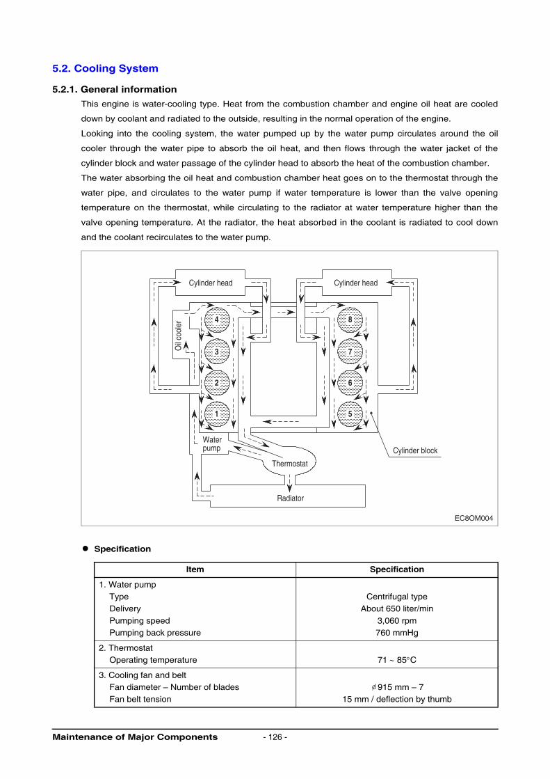
5.2. Cooling System
5.2.1. General information
This engine is water-cooling type. Heat from the combustion chamber and engine oil heat are cooled
down by coolant and radiated to the outside, resulting in the normal operation of the engine.
Looking into the cooling system, the water pumped up by the water pump circulates around the oil
cooler through the water pipe to absorb the oil heat, and then flows through the water jacket of the
cylinder block and water passage of the cylinder head to absorb the heat of the combustion chamber.
The water absorbing the oil heat and combustion chamber heat goes on to the thermostat through the
water pipe, and circulates to the water pump if water temperature is lower than the valve opening
temperature on the thermostat, while circulating to the radiator at water temperature higher than the
valve opening temperature. At the radiator, the heat absorbed in the coolant is radiated to cool down
and the coolant recirculates to the water pump.
Specification
Item Specification
1. Water pumpType
Delivery
Pumping speedPumping back pressure
Centrifugal type
About 650 liter/min
3,060 rpm760 mmHg
2. ThermostatOperating temperature 71 ∼ 85°C
3. Cooling fan and beltFan diameter – Number of blades
Fan belt tension
915 mm – 7
15 mm / deflection by thumb
EC8OM004
Thermostat
Waterpump
Cylinder head
Oil
cool
er
Cylinder head
Radiator
Cylinder block
1
2
3
44
5
6
7
48
Maintenance of Major Components - 126 -
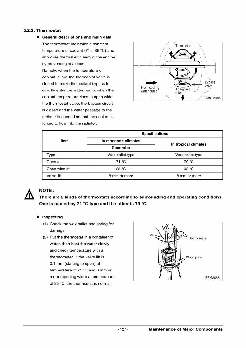
5.2.2. Thermostat
General descriptions and main data
The thermostat maintains a constant
temperature of coolant (71 ~ 85 °C) and
improves thermal efficiency of the engine
by preventing heat loss.
Namely, when the temperature of
coolant is low, the thermostat valve is
closed to make the coolant bypass to
directly enter the water pump; when the
coolant temperature rises to open wide
the thermostat valve, the bypass circuit
is closed and the water passage to the
radiator is opened so that the coolant is
forced to flow into the radiator.
NOTE :
There are 2 kinds of thermostats according to surrounding and operating conditions.
One is named by 71 °C type and the other is 79 °C.
Inspecting
(1) Check the wax pallet and spring for
damage.
(2) Put the thermostat in a container of
water, then heat the water slowly
and check temperature with a
thermometer. If the valve lift is
0.1 mm (starting to open) at
temperature of 71 °C and 8 mm or
more (opening wide) at temperature
of 85 °C, the thermostat is normal.
Item
Specifications
In moderate climatesIn tropical climates
Generator
Type Wax-pallet type Wax-pallet type
Open at 71 °C 79 °C
Open wide at 85 °C 93 °C
Valve lift 8 mm or more 8 mm or more
EC8OM005
To radiator
BypassvalveFrom cooling
water pump To bypasstube
EFM2055I
Thermometer
Wood plate
Bar
Maintenance of Major Components- 127 -
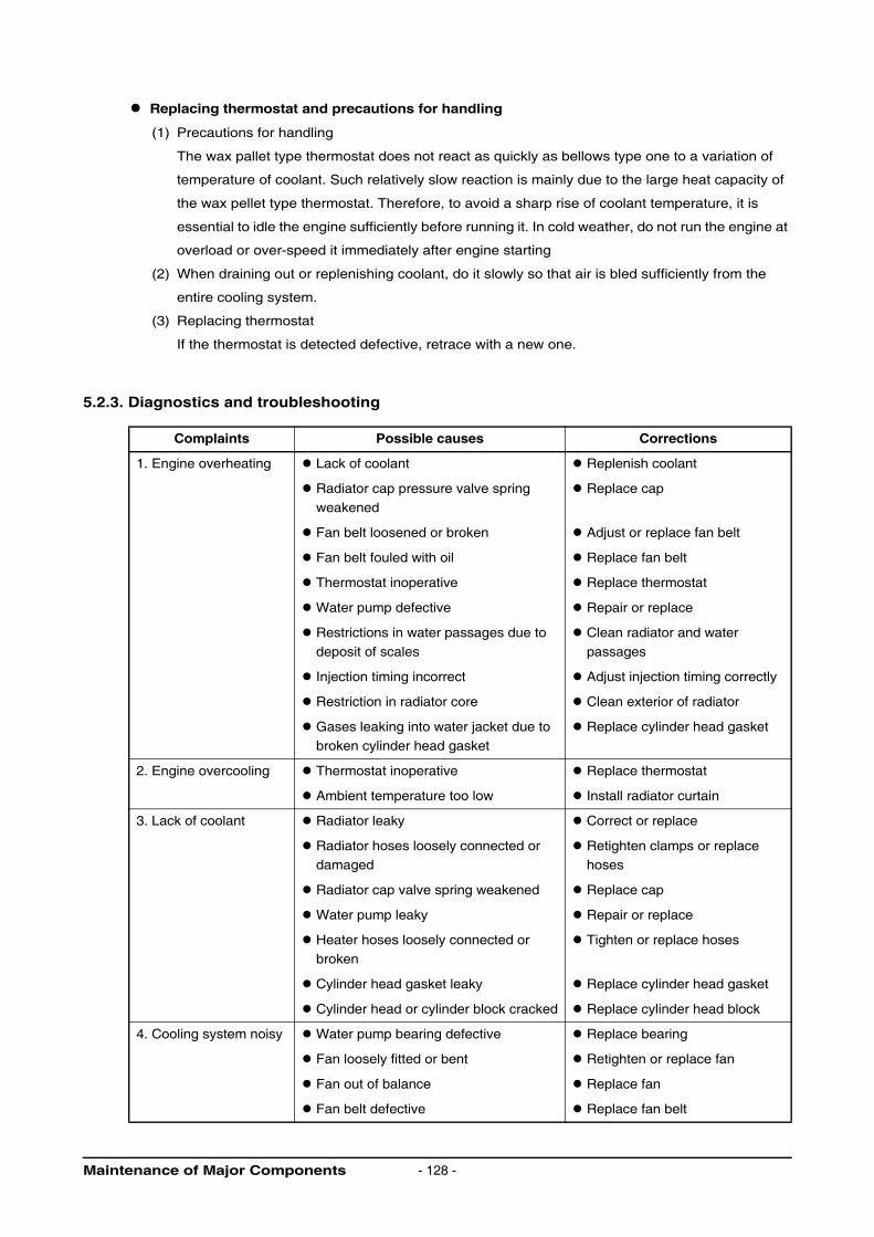
Replacing thermostat and precautions for handling
(1) Precautions for handling
The wax pallet type thermostat does not react as quickly as bellows type one to a variation of
temperature of coolant. Such relatively slow reaction is mainly due to the large heat capacity of
the wax pellet type thermostat. Therefore, to avoid a sharp rise of coolant temperature, it is
essential to idle the engine sufficiently before running it. In cold weather, do not run the engine at
overload or over-speed it immediately after engine starting
(2) When draining out or replenishing coolant, do it slowly so that air is bled sufficiently from the
entire cooling system.
(3) Replacing thermostat
If the thermostat is detected defective, retrace with a new one.
5.2.3. Diagnostics and troubleshooting
Complaints Possible causes Corrections
1. Engine overheating Lack of coolant Replenish coolant
Radiator cap pressure valve spring
weakened
Replace cap
Fan belt loosened or broken Adjust or replace fan belt
Fan belt fouled with oil Replace fan belt
Thermostat inoperative Replace thermostat
Water pump defective Repair or replace
Restrictions in water passages due to
deposit of scales
Clean radiator and water
passages
Injection timing incorrect Adjust injection timing correctly
Restriction in radiator core Clean exterior of radiator
Gases leaking into water jacket due to broken cylinder head gasket
Replace cylinder head gasket
2. Engine overcooling Thermostat inoperative Replace thermostat
Ambient temperature too low Install radiator curtain
3. Lack of coolant Radiator leaky Correct or replace
Radiator hoses loosely connected or damaged
Retighten clamps or replace hoses
Radiator cap valve spring weakened Replace cap
Water pump leaky Repair or replace
Heater hoses loosely connected or
broken
Tighten or replace hoses
Cylinder head gasket leaky Replace cylinder head gasket
Cylinder head or cylinder block cracked Replace cylinder head block
4. Cooling system noisy Water pump bearing defective Replace bearing
Fan loosely fitted or bent Retighten or replace fan
Fan out of balance Replace fan
Fan belt defective Replace fan belt
Maintenance of Major Components - 128 -
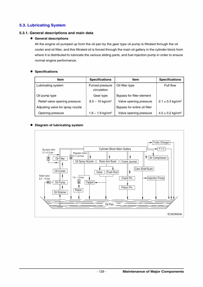
5.3. Lubricating System
5.3.1. General descriptions and main data
General descriptions
All the engine oil pumped up from the oil pan by the gear type oil pump is filtrated through the oil
cooler and oil filter, and this filtrated oil is forced through the main oil gallery in the cylinder block from
where it is distributed to lubricate the various sliding parts, and fuel injection pump in order to ensure
normal engine performance.
Specifications
Diagram of lubricating system
Item Specifications Item Specifications
Lubricating system Forced pressurecirculation
Oil filter type Full flow
Oil pump type Gear type Bypass for filter element
Relief valve opening pressure 8.5 ~ 10 kg/cm2 Valve opening pressure 2.1 ± 0.3 kg/cm2
Adjusting valve for spray nozzle Bypass for entire oil filter
Opening pressure 1.6 ∼ 1.9 kg/cm2 Valve opening pressure 4.5 ± 0.2 kg/cm2
EC8OM006
By-pass valve2.1 0.3 bar Regulator Valve
2.1 0.3 bar
Relief valve8.5 ~ 10 bar
Oil Strainer
Oil Pump
Oil Cooler
Oil Spray Nozzle
Piston
Tappet
Valve Push Rod
Crank Pin
Cam Shaft Bush
Injection Pump
Air Compressor
P.T.O
Turbo Charger
Piston Pin
Oil Pan
Rock Arm Bush Crank Journal
Cylinder Block Main Gallery
Oil Filter
1.6 ~ 1.9 bar
Maintenance of Major Components- 129 -
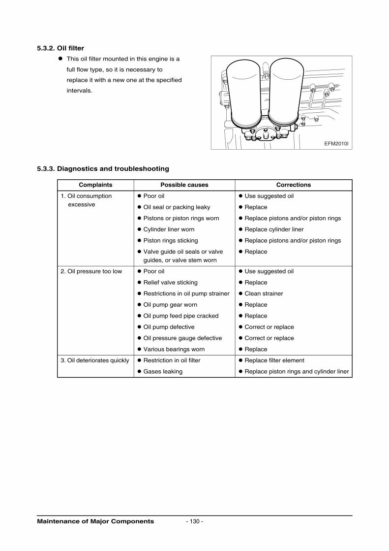
5.3.2. Oil filter
This oil filter mounted in this engine is a
full flow type, so it is necessary to
replace it with a new one at the specified
intervals.
5.3.3. Diagnostics and troubleshooting
Complaints Possible causes Corrections
1. Oil consumption
excessive
Poor oil Use suggested oil
Oil seal or packing leaky Replace
Pistons or piston rings worn Replace pistons and/or piston rings
Cylinder liner worn Replace cylinder liner
Piston rings sticking Replace pistons and/or piston rings
Valve guide oil seals or valve
guides, or valve stem worn
Replace
2. Oil pressure too low
Poor oil Use suggested oil
Relief valve sticking Replace
Restrictions in oil pump strainer Clean strainer
Oil pump gear worn Replace
Oil pump feed pipe cracked Replace
Oil pump defective Correct or replace
Oil pressure gauge defective Correct or replace
Various bearings worn Replace
3. Oil deteriorates quickly Restriction in oil filter Replace filter element
Gases leaking Replace piston rings and cylinder liner
EFM2010I
Maintenance of Major Components - 130 -
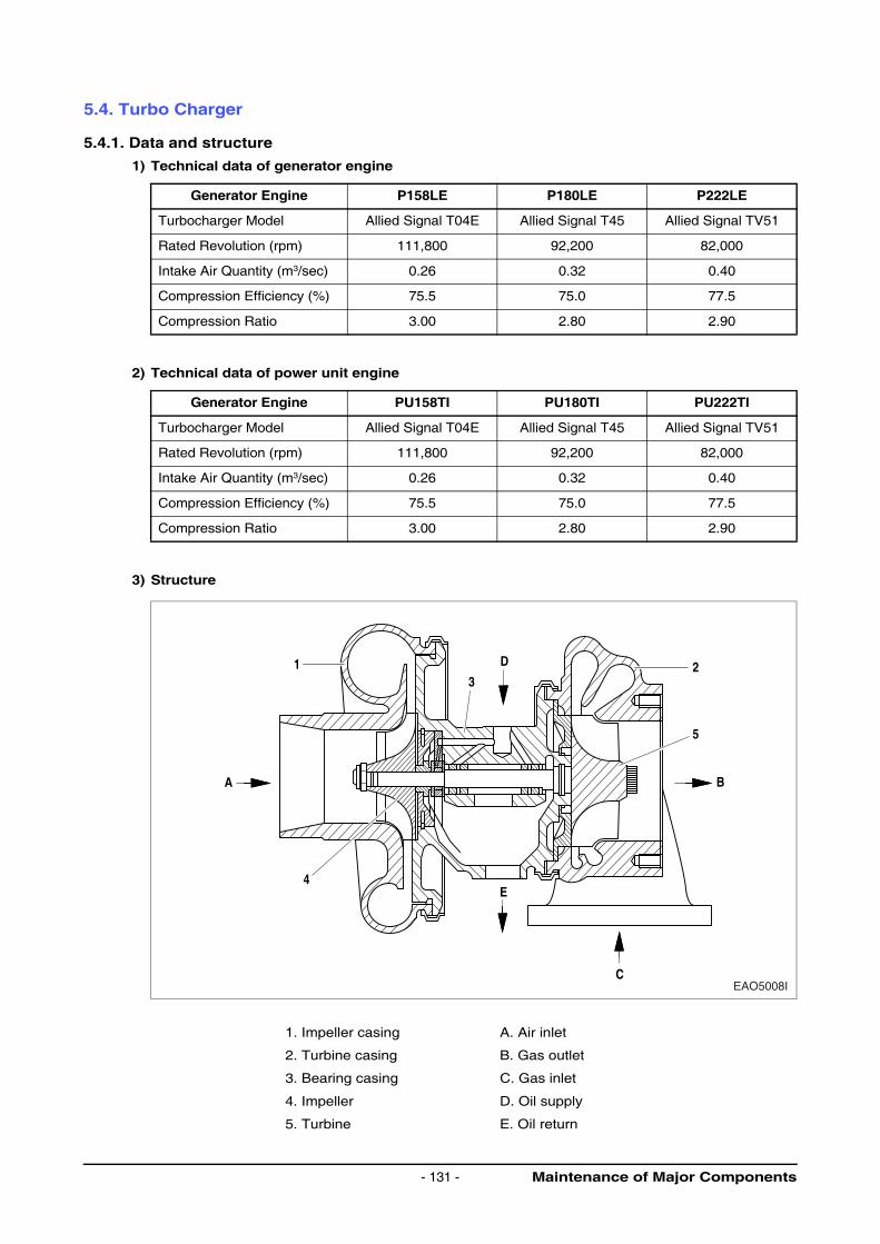
5.4. Turbo Charger
5.4.1. Data and structure
1) Technical data of generator engine
2) Technical data of power unit engine
3) Structure
Generator Engine P158LE P180LE P222LE
Turbocharger Model Allied Signal T04E Allied Signal T45 Allied Signal TV51
Rated Revolution (rpm) 111,800 92,200 82,000
Intake Air Quantity (m3/sec) 0.26 0.32 0.40
Compression Efficiency (%) 75.5 75.0 77.5
Compression Ratio 3.00 2.80 2.90
Generator Engine PU158TI PU180TI PU222TI
Turbocharger Model Allied Signal T04E Allied Signal T45 Allied Signal TV51
Rated Revolution (rpm) 111,800 92,200 82,000
Intake Air Quantity (m3/sec) 0.26 0.32 0.40
Compression Efficiency (%) 75.5 75.0 77.5
Compression Ratio 3.00 2.80 2.90
1. Impeller casing A. Air inlet
2. Turbine casing B. Gas outlet
3. Bearing casing C. Gas inlet
4. Impeller D. Oil supply
5. Turbine E. Oil return
EAO5008IC
5
32
B
E4
1
A
D
Maintenance of Major Components- 131 -
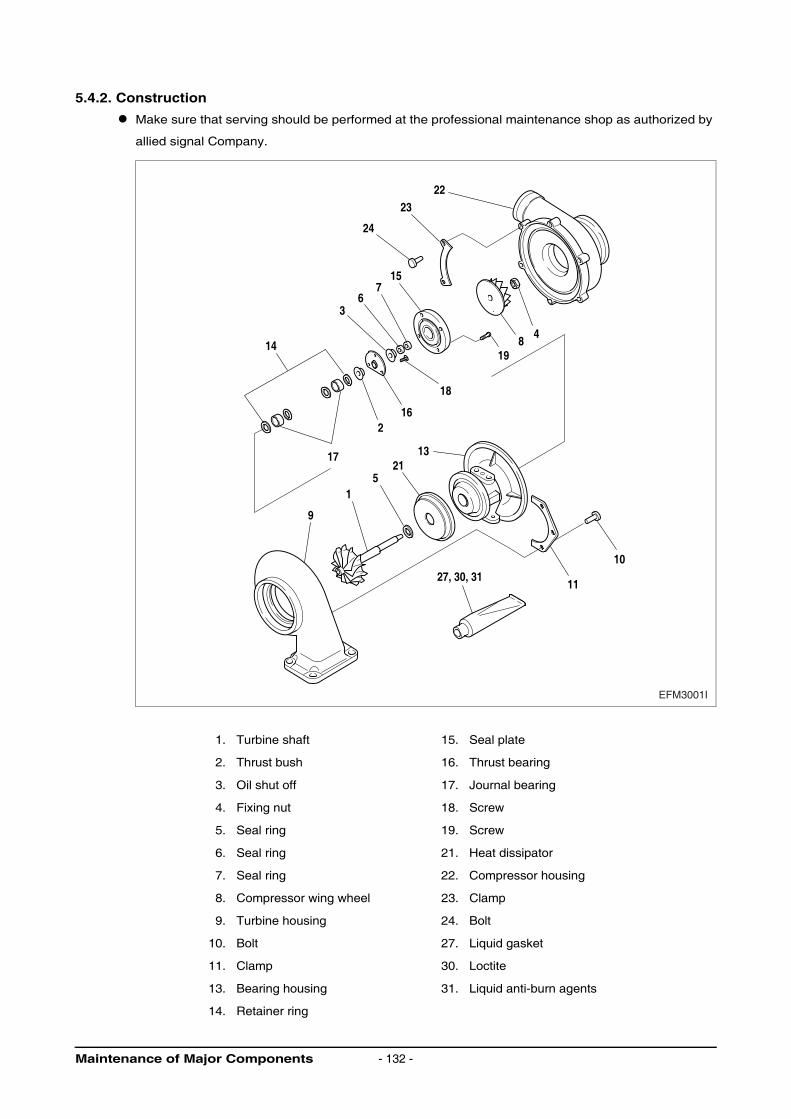
5.4.2. Construction
Make sure that serving should be performed at the professional maintenance shop as authorized by
allied signal Company.
1. Turbine shaft 15. Seal plate
2. Thrust bush 16. Thrust bearing
3. Oil shut off 17. Journal bearing
4. Fixing nut 18. Screw
5. Seal ring 19. Screw
6. Seal ring 21. Heat dissipator
7. Seal ring 22. Compressor housing
8. Compressor wing wheel 23. Clamp
9. Turbine housing 24. Bolt
10. Bolt 27. Liquid gasket
11. Clamp 30. Loctite
13. Bearing housing 31. Liquid anti-burn agents
14. Retainer ring
2223
24
15
1914
18
16
17 1321
11
1027, 30, 31
7
48
6
2
5
9
1
3
EFM3001I
Maintenance of Major Components - 132 -
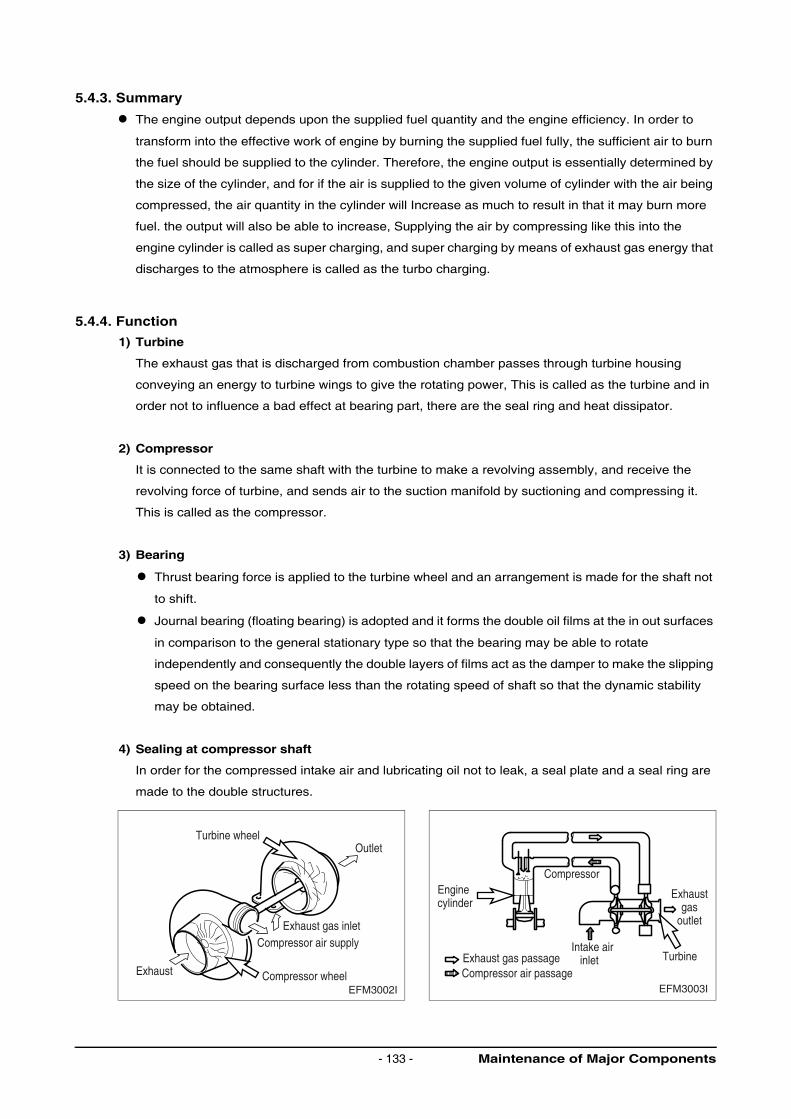
5.4.3. Summary
The engine output depends upon the supplied fuel quantity and the engine efficiency. In order to
transform into the effective work of engine by burning the supplied fuel fully, the sufficient air to burn
the fuel should be supplied to the cylinder. Therefore, the engine output is essentially determined by
the size of the cylinder, and for if the air is supplied to the given volume of cylinder with the air being
compressed, the air quantity in the cylinder will Increase as much to result in that it may burn more
fuel. the output will also be able to increase, Supplying the air by compressing like this into the
engine cylinder is called as super charging, and super charging by means of exhaust gas energy that
discharges to the atmosphere is called as the turbo charging.
5.4.4. Function
1) Turbine
The exhaust gas that is discharged from combustion chamber passes through turbine housing
conveying an energy to turbine wings to give the rotating power, This is called as the turbine and in
order not to influence a bad effect at bearing part, there are the seal ring and heat dissipator.
2) Compressor
It is connected to the same shaft with the turbine to make a revolving assembly, and receive the
revolving force of turbine, and sends air to the suction manifold by suctioning and compressing it.
This is called as the compressor.
3) Bearing
Thrust bearing force is applied to the turbine wheel and an arrangement is made for the shaft not
to shift.
Journal bearing (floating bearing) is adopted and it forms the double oil films at the in out surfaces
in comparison to the general stationary type so that the bearing may be able to rotate
independently and consequently the double layers of films act as the damper to make the slipping
speed on the bearing surface less than the rotating speed of shaft so that the dynamic stability
may be obtained.
4) Sealing at compressor shaft
In order for the compressed intake air and lubricating oil not to leak, a seal plate and a seal ring are
made to the double structures.
EFM3002I
Turbine wheel
Compressor wheel
Compressor air supply
Exhaust
Exhaust gas inlet
Outlet
EFM3003I
TurbineIntake air inlet
Compressor air passage
Compressor
Exhaust gas passage
Exhaustgas
outlet
Enginecylinder
Maintenance of Major Components- 133 -
5.4.5. Maintenance
The turbochargers do not call for any specific maintenance.
The only points to be observed are the oil pipes which should be checked at every oil change for
leakage and restrictions.
The air cleaners should be carefully serviced.
Furthermore, a regular check should be kept on charge air and exhaust gas pipes. Any leakage should
be attended to at once because they are liable to cause overheating of the engine.
When operating in highly dust or oil laden atmospheres, cleaning of the air impeller may be necessary
from time to time. To do this, remove compressor casing (Caution : Do not skew it!) and clean in non-
acid solvent, if necessary using a plastic scraper.
If the air compressor should be badly fouled, it is recommended that the wheel be allowed to soak in a
vessel with solvent and to clean it then with a stiff brush. In doing so, take care to see that only the
compressor wheel is immersed and that the turbocharger is supported on the bearing casing and not on
the wheel.
Maintenance of Major Components - 134 -
5.4.6. Handling
1) Precautions at engine
Operation following items must be observed at the starting, operation and stop of engine.
Item Care Items
At starting 1) Inspect oil quantity
2) After confirming that oil pressure rises
by starting engine with starter (until the pointer of oil pressure gauge moves or
pressure indicating lamp operates),
the starting must be done.
2) If engine is started quickly, of course
beginning with every parts of engine, for it revolves without oil that is to reach to
the turbocharger, the bearing’s abnormal
wear or stuck may be caused.
3) In case that oil, oil filter and lubricating
system’s part are replaced or engine was stalled for long time (more than a
week), and in case of operation under
cold weather, loosen the oil pipe connecting parts of turbocharger inlet,
and operate the starting motor until oil
comes out the connecting parts. Care must be paid that after the confirming
above, retighten the pipe connecting
parts without fail, and proceed with the normal starting.
3) In case that engine stalled for long time
and of cold weather, the fluidity of oil may be get worse.
Immediately
after starting
1) Perform idling operation for about
5 min. immediately after engine starting.
1) Sudden load at time soon after engine
starting and at the state when turbocharger did not yet reach to smooth
revolution, if abrupt load is applied to
engine, some parts where oil did still not reach may cause a burn to be stuck.
2) Various inspections must insure that there are no leakage of oil, gas and
air.
2) If there are the leakage of oil, gas, air, particularly oil, for the oil pressure
lowers, it causes a burn of bearing to be
stuck.
During
operation
Following items must be confirmed.
1) Oil pressure at
Idling : 90 ~ 300 kPa (0.9 ~ 3.0 bar)
at full load : 300 ~ 650 kPa (3.0 ~ 6.5 bar)
1) If the pressure is too low, abnormal wear
or stuck may be caused. Or if too high,
the oil leak may be generated.
2) When abnormal noises and vibration are generated, slow down the
revolution and must stop it to
investigate the causes.
2) If the engine operation were continued with abnormal noises and vibration, it
causes the engine trouble that can not
be repaired or some other troubles.
At stop 1) At stopping the engine, perform the
idling operation for 5 min. and then stop it.
1) After heavy load operation, if the engine
were stopped suddenly, the heat would be conducted to bearing parts from red
hot turbine wings that would result in
burning the oil to cause the stuck bearing metal and revolving shaft.
Maintenance of Major Components- 135 -
5.4.7. Routine inspection and maintenance
Since the state of turbocharger depends largely on the state of engine maintenance, to perform the
specified up keep thoroughly is needed.
1) Intake air
System in the intake air system, care must be taken to the air cleaner. In case of oil passing type air
cleaner, if the oil level is lower than the specified value, the cleaning efficiency get worse, if higher,
the sucked oil pollutes a case. Particularly, for if the rotor were polluted, the balance adjusted
precisely would be deviated to cause a vibration that may cause the stuck or abnormal wear by
loading large force to the bearing, the perfect air cleaner must always be used. In case of dry type
filter, according to the indication of a dust indicator, cleaning must be done to make the intake air
resistance as small as possible.
2) Exhaust system
In exhaust system, a care must be taken to the gas leak and the stuck prevention If exhaust gas
leaks from the exhaust pipe and turbocharger etc., for the super charging effect will be lowered, the
installed states of various parts must be paid with careful attention. Since the parts that reach to high
temperature during operation such as the turbine room use the anti- heat nuts, a care must be paid
not to mix with the general nuts and at the same time, bolt stuck preventing paint should be coated
on the nut for the designated places.
3) Fuel system
If the full load stopper that restricts the maximum fuel injection quantity of fuel injection pump and the
maximum speed stopper that restricts the maximum speed are adjusted without the pump tester, the
turbocharger may overrun to be damaged. Also, if the atomizing state of fuel injection nozzle
becomes worse or the injection timing gets wrong, for the raised temperature of exhaust gas will
influence badly to the turbocharger, the nozzle testing must be done.
4) Lubricating system
In the lubricating system, a care must be paid to the oil quality and oil element replacement cycle.
For the oil deterioration of turbocharger equipped engine, needless to speak of engine assembly
itself, influences badly to the turbocharger too, the specified engine oil (15W40, CE class) should
used.
Maintenance of Major Components - 136 -
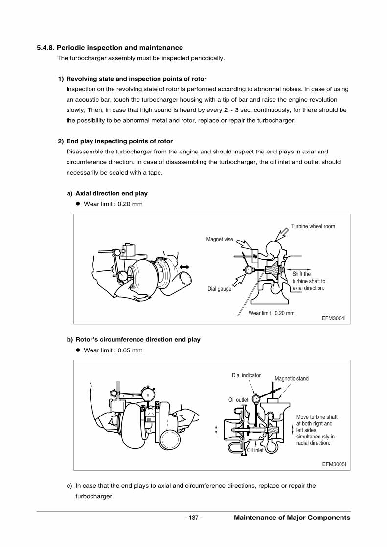
5.4.8. Periodic inspection and maintenance
The turbocharger assembly must be inspected periodically.
1) Revolving state and inspection points of rotor
Inspection on the revolving state of rotor is performed according to abnormal noises. In case of using
an acoustic bar, touch the turbocharger housing with a tip of bar and raise the engine revolution
slowly, Then, in case that high sound is heard by every 2 ~ 3 sec. continuously, for there should be
the possibility to be abnormal metal and rotor, replace or repair the turbocharger.
2) End play inspecting points of rotor
Disassemble the turbocharger from the engine and should inspect the end plays in axial and
circumference direction. In case of disassembling the turbocharger, the oil inlet and outlet should
necessarily be sealed with a tape.
a) Axial direction end play
Wear limit : 0.20 mm
b) Rotor’s circumference direction end play
Wear limit : 0.65 mm
c) In case that the end plays to axial and circumference directions, replace or repair the
turbocharger.
Magnet vise
Turbine wheel room
Dial gauge
Shift theturbine shaft toaxial direction.
Wear limit : 0.20 mmEFM3004I
EFM3005I
Dial indicator Magnetic stand
Oil outlet
Oil inlet
Move turbine shaftat both right andleft sidessimultaneously inradial direction.
Maintenance of Major Components- 137 -
3) Overhaul and cleaning points
Disassemble the turbocharger from engine and perform a cleaning and inspection, and in this case,
the oil inlet and outlet should necessarily be sealed with tape etc.
4) Precautions in assembling engine
When in assembling the turbocharger or the handling after assembling should work observing the
following precautions necessarily. Particularly, precise care should be taken for foreign material not
to get into the turbocharger.
a) Lubricating system
Prior to assembling it into the engine, fill new oil into oil Inlet and turning turbine shaft with
hand, lubricate journal and thrust bearing.
Clean the pipe and oil outlet pipe between engine and oil inlet, and confirm if there is any pipe
damage or foreign material.
In order for oil not to leak from various connections, assemble securely.
b) Air intake system
Confirm if there is any foreign material inside the air intake system.
Assemble securely the air intake duct and air cleaner so that the connections from them may
not leak an air.
c) Exhaust system
Confirm if there is any foreign material in the exhaust system.
Bolts and nuts must be made of anti-heat steel and in assembling, care should be taken not
use the general nuts and coat the bolts and nuts with the anti-stuck agents at the same time.
Assemble securely for gas not to leak from various connecting parts of exhaust pipes.
Maintenance of Major Components - 138 -
5.4.9. Trouble cause diagnosis and remedy
Condition Causes Remedies
1. Exhaust gas excessive
1) Air cleaner elements clogged Replace or clean
2) Air Inlet port clogged Inspect or repair
3) Air leaks from air intake system Inspect or repair
4) Turbocharger impossible to rotate due to stuck Overhaul and repair or replace
5) Turbine wing’s contact Overhaul and repair or replace
6) Piping deformation or clogging of exhaust
system
Inspect and repair
2. White smoke
excessive
1) Oil leaks into turbine and compressor. Overhaul and repair or replace
2) Seal ring’s abnormal wear or damage Overhaul and repair or replace
3. Output lowered 1) Gas leak from various parts of exhaust system Inspect and repair
2) Air cleaner’s elements clogged Replace or clean
3) Turbocharger’s pollution or damage Overhaul and repair or replace
4) Air leaks from discharge part of compressor
side
Inspect and repair
4. Abnormal noises
or vibrations
1) Revolving part’s contact Overhaul and repair or replace
2) Revolving imbalance of rotor Overhaul and repair or replace
3) Stuck Overhaul and repair or replace
4) Various connections loose Inspect and repair
Maintenance of Major Components- 139 -
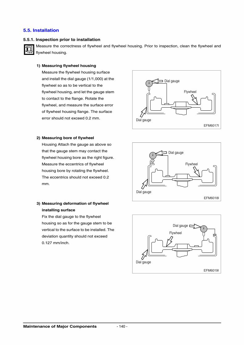
5.5. Installation
5.5.1. Inspection prior to installation
Measure the correctness of flywheel and flywheel housing. Prior to inspection, clean the flywheel and
flywheel housing.
1) Measuring flywheel housing
Measure the flywheel housing surface
and install the dial gauge (1/1,000) at the
flywheel so as to be vertical to the
flywheel housing, and let the gauge stem
to contact to the flange. Rotate the
flywheel, and measure the surface error
of flywheel housing flange. The surface
error should not exceed 0.2 mm.
2) Measuring bore of flywheel
Housing Attach the gauge as above so
that the gauge stem may contact the
flywheel housing bore as the right figure.
Measure the eccentrics of flywheel
housing bore by rotating the flywheel.
The eccentrics should not exceed 0.2
mm.
3) Measuring deformation of flywheel
installing surface
Fix the dial gauge to the flywheel
housing so as for the gauge stem to be
vertical to the surface to be installed. The
deviation quantity should not exceed
0.127 mm/inch.
Dial gauge
Dial gauge
Flywheel
EFM6017I
Dial gauge
Dial gauge
Flywheel
EFM6018I
Dial gauge
Dial gauge
Flywheel
EFM6019I
Maintenance of Major Components - 140 -
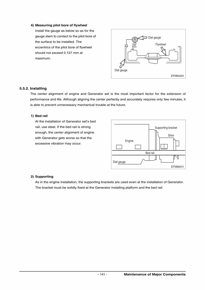
4) Measuring pilot bore of flywheel
Install the gauge as below so as for the
gauge stem to contact to the pilot bore of
the surface to be installed. The
eccentrics of the pilot bore of flywheel
should not exceed 0.127 mm at
maximum.
5.5.2. Installing
The center alignment of engine and Generator set is the most important factor for the extension of
performance and life. Although aligning the center perfectly and accurately requires only few minutes, it
is able to prevent unnecessary mechanical trouble at the future.
1) Bed rail
At the installation of Generator set’s bed
rail, use steel, If the bed rail is strong
enough, the center alignment of engine
with Generator gets worse so that the
excessive vibration may occur.
2) Supporting
As in the engine installation, the supporting brackets are used even at the installation of Generator.
The bracket must be solidly fixed at the Generator installing platform and the bed rail.
Dial gauge
Dial gauge
Flywheel
EFM6020I
Engine
Bed rail
Dial gauge
Shim
Supporting bracket
EFM8001I
Maintenance of Major Components- 141 -
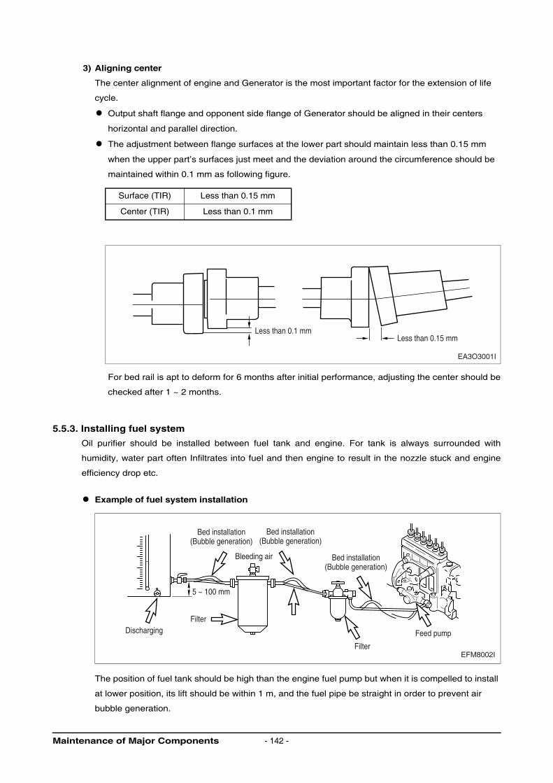
3) Aligning center
The center alignment of engine and Generator is the most important factor for the extension of life
cycle.
Output shaft flange and opponent side flange of Generator should be aligned in their centers
horizontal and parallel direction.
The adjustment between flange surfaces at the lower part should maintain less than 0.15 mm
when the upper part’s surfaces just meet and the deviation around the circumference should be
maintained within 0.1 mm as following figure.
For bed rail is apt to deform for 6 months after initial performance, adjusting the center should be
checked after 1 ~ 2 months.
5.5.3. Installing fuel system
Oil purifier should be installed between fuel tank and engine. For tank is always surrounded with
humidity, water part often Infiltrates into fuel and then engine to result in the nozzle stuck and engine
efficiency drop etc.
Example of fuel system installation
The position of fuel tank should be high than the engine fuel pump but when it is compelled to install
at lower position, its lift should be within 1 m, and the fuel pipe be straight in order to prevent air
bubble generation.
Surface (TIR) Less than 0.15 mm
Center (TIR) Less than 0.1 mm
EA3O3001I
Less than 0.1 mmLess than 0.15 mm
Bed installation(Bubble generation)
Bed installation(Bubble generation)
Bed installation(Bubble generation)
Bleeding air
Filter
Filter
Feed pump
5 ~ 100 mm
Discharging
EFM8002I
Maintenance of Major Components - 142 -
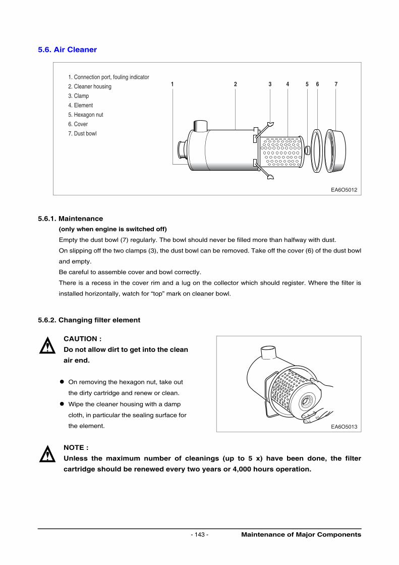
5.6. Air Cleaner
5.6.1. Maintenance
(only when engine is switched off)
Empty the dust bowl (7) regularly. The bowl should never be filled more than halfway with dust.
On slipping off the two clamps (3), the dust bowl can be removed. Take off the cover (6) of the dust bowl
and empty.
Be careful to assemble cover and bowl correctly.
There is a recess in the cover rim and a lug on the collector which should register. Where the filter is
installed horizontally, watch for “top” mark on cleaner bowl.
5.6.2. Changing filter element
CAUTION :
Do not allow dirt to get into the clean
air end.
On removing the hexagon nut, take out
the dirty cartridge and renew or clean.
Wipe the cleaner housing with a damp
cloth, in particular the sealing surface for
the element.
NOTE :
Unless the maximum number of cleanings (up to 5 x) have been done, the filter
cartridge should be renewed every two years or 4,000 hours operation.
EA6O5012
1. Connection port, fouling indicator
2. Cleaner housing
3. Clamp
4. Element
5. Hexagon nut
6. Cover
7. Dust bowl
1 2 3 4 5 6 7
EA6O5013
Maintenance of Major Components- 143 -
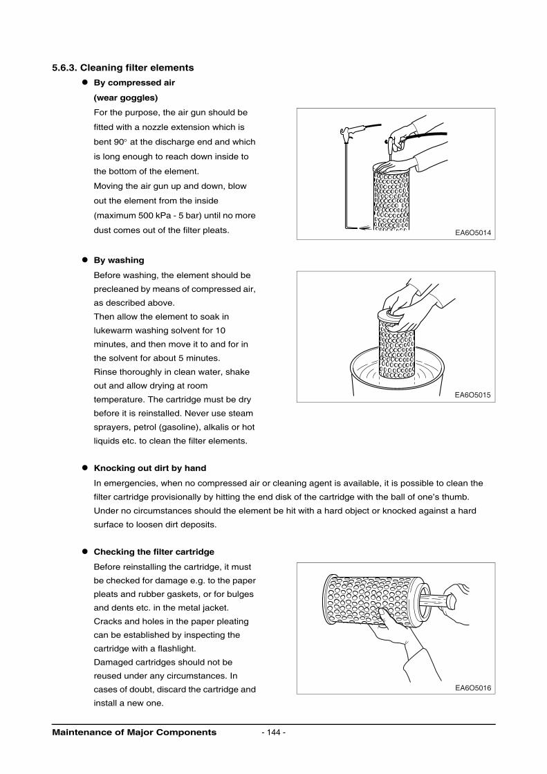
5.6.3. Cleaning filter elements
By compressed air
(wear goggles)
For the purpose, the air gun should be
fitted with a nozzle extension which is
bent 90° at the discharge end and which
is long enough to reach down inside to
the bottom of the element.
Moving the air gun up and down, blow
out the element from the inside
(maximum 500 kPa - 5 bar) until no more
dust comes out of the filter pleats.
By washing
Before washing, the element should be
precleaned by means of compressed air,
as described above.
Then allow the element to soak in
lukewarm washing solvent for 10
minutes, and then move it to and for in
the solvent for about 5 minutes.
Rinse thoroughly in clean water, shake
out and allow drying at room
temperature. The cartridge must be dry
before it is reinstalled. Never use steam
sprayers, petrol (gasoline), alkalis or hot
liquids etc. to clean the filter elements.
Knocking out dirt by hand
In emergencies, when no compressed air or cleaning agent is available, it is possible to clean the
filter cartridge provisionally by hitting the end disk of the cartridge with the ball of one’s thumb.
Under no circumstances should the element be hit with a hard object or knocked against a hard
surface to loosen dirt deposits.
Checking the filter cartridge
Before reinstalling the cartridge, it must
be checked for damage e.g. to the paper
pleats and rubber gaskets, or for bulges
and dents etc. in the metal jacket.
Cracks and holes in the paper pleating
can be established by inspecting the
cartridge with a flashlight.
Damaged cartridges should not be
reused under any circumstances. In
cases of doubt, discard the cartridge and
install a new one.
EA6O5014
EA6O5015
EA6O5016
Maintenance of Major Components - 144 -
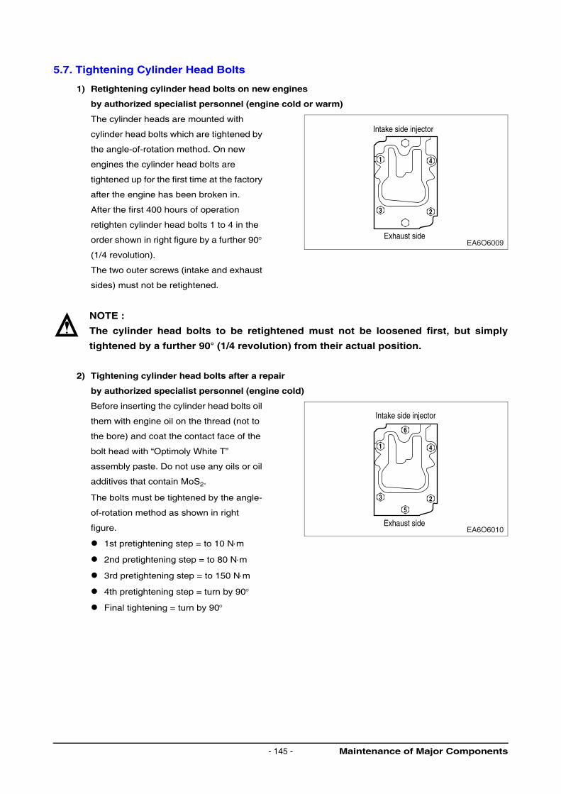
5.7. Tightening Cylinder Head Bolts
1) Retightening cylinder head bolts on new engines
by authorized specialist personnel (engine cold or warm)
The cylinder heads are mounted with
cylinder head bolts which are tightened by
the angle-of-rotation method. On new
engines the cylinder head bolts are
tightened up for the first time at the factory
after the engine has been broken in.
After the first 400 hours of operation
retighten cylinder head bolts 1 to 4 in the
order shown in right figure by a further 90°
(1/4 revolution).
The two outer screws (intake and exhaust
sides) must not be retightened.
NOTE :
The cylinder head bolts to be retightened must not be loosened first, but simply
tightened by a further 90° (1/4 revolution) from their actual position.
2) Tightening cylinder head bolts after a repair
by authorized specialist personnel (engine cold)
Before inserting the cylinder head bolts oil
them with engine oil on the thread (not to
the bore) and coat the contact face of the
bolt head with “Optimoly White T”
assembly paste. Do not use any oils or oil
additives that contain MoS2.
The bolts must be tightened by the angle-
of-rotation method as shown in right
figure.
1st pretightening step = to 10 N⋅m
2nd pretightening step = to 80 N⋅m
3rd pretightening step = to 150 N⋅m
4th pretightening step = turn by 90°
Final tightening = turn by 90°
1
Intake side injector
Exhaust side
4
3 2
EA6O6009
1
Intake side injector
Exhaust side
4
3
5
6
2
EA6O6010
Maintenance of Major Components- 145 -
3) Retightening cylinder head bolts after repairs by authorized specialist personnel (engine cold
or warm)
After the first 10 to 20 hours of operation after a repair turn the cylinder head bolts by a further 90° (1/
4 revolution) in the order shown in above figure. ((2) Tightening cylinder head bolts after repair)
The cylinder head bolts to be retightened must not be loosened first, but simply tightened by a further
90° (1/4 revolution) from their actual position.
Attach the sticker “First retightening of cylinder head bolts ...”(Remove any other stickers which may
already be attached).
After the first 400 hours of operation after a repair tighten cylinder head bolts 1 to 4 in the order shown
in above figure ((1) Retightening cylinder head bolts on new engines) again by a further 90° (1/4
revolution).
The two outside screws (intake and exhaust side) must not be retightened.
NOTE :
When a cylinder head has been removed the cylinder head gasket must always be
changed.
Maintenance of Major Components - 146 -
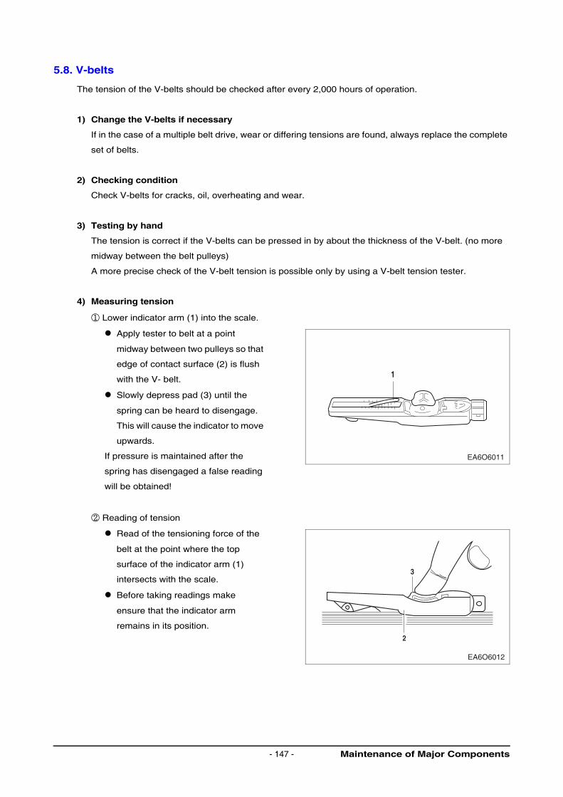
5.8. V-belts
The tension of the V-belts should be checked after every 2,000 hours of operation.
1) Change the V-belts if necessary
If in the case of a multiple belt drive, wear or differing tensions are found, always replace the complete
set of belts.
2) Checking condition
Check V-belts for cracks, oil, overheating and wear.
3) Testing by hand
The tension is correct if the V-belts can be pressed in by about the thickness of the V-belt. (no more
midway between the belt pulleys)
A more precise check of the V-belt tension is possible only by using a V-belt tension tester.
4) Measuring tension
① Lower indicator arm (1) into the scale.
Apply tester to belt at a point
midway between two pulleys so that
edge of contact surface (2) is flush
with the V- belt.
Slowly depress pad (3) until the
spring can be heard to disengage.
This will cause the indicator to move
upwards.
If pressure is maintained after the
spring has disengaged a false reading
will be obtained!
② Reading of tension
Read of the tensioning force of the
belt at the point where the top
surface of the indicator arm (1)
intersects with the scale.
Before taking readings make
ensure that the indicator arm
remains in its position.
1
EA6O6011
3
2
EA6O6012
Maintenance of Major Components- 147 -
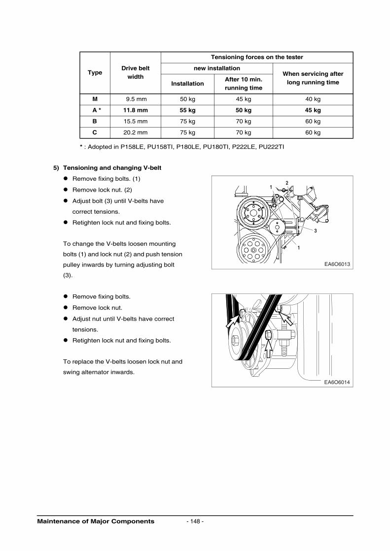
* : Adopted in P158LE, PU158TI, P180LE, PU180TI, P222LE, PU222TI
5) Tensioning and changing V-belt
Remove fixing bolts. (1)
Remove lock nut. (2)
Adjust bolt (3) until V-belts have
correct tensions.
Retighten lock nut and fixing bolts.
To change the V-belts loosen mounting
bolts (1) and lock nut (2) and push tension
pulley inwards by turning adjusting bolt
(3).
Remove fixing bolts.
Remove lock nut.
Adjust nut until V-belts have correct
tensions.
Retighten lock nut and fixing bolts.
To replace the V-belts loosen lock nut and
swing alternator inwards.
TypeDrive belt
width
Tensioning forces on the tester
new installationWhen servicing after
long running timeInstallationAfter 10 min.running time
M 9.5 mm 50 kg 45 kg 40 kg
A * 11.8 mm 55 kg 50 kg 45 kg
B 15.5 mm 75 kg 70 kg 60 kg
C 20.2 mm 75 kg 70 kg 60 kg
EA6O6013
3
1
21
EA6O6014
Maintenance of Major Components - 148 -
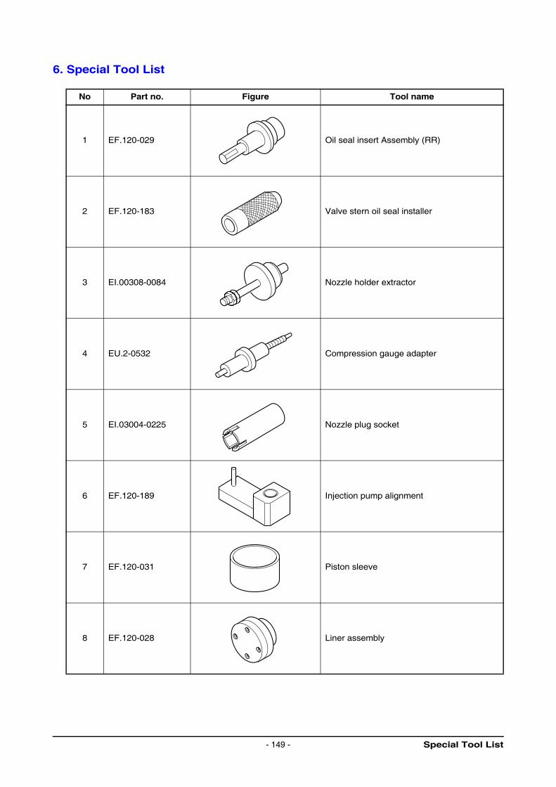
6. Special Tool List
No Part no. Figure Tool name
1 EF.120-029 Oil seal insert Assembly (RR)
2 EF.120-183 Valve stern oil seal installer
3 EI.00308-0084 Nozzle holder extractor
4 EU.2-0532 Compression gauge adapter
5 EI.03004-0225 Nozzle plug socket
6 EF.120-189 Injection pump alignment
7 EF.120-031 Piston sleeve
8 EF.120-028 Liner assembly
Special Tool List- 149 -
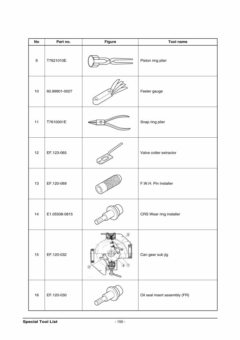
No Part no. Figure Tool name
9 T7621010E Piston ring plier
10 60.99901-0027 Feeler gauge
11 T7610001E Snap ring plier
12 EF.123-065 Valve cotter extractor
13 EF.120-069 F.W.H. Pin installer
14 E1.05508-0815 CRS Wear ring installer
15 EF.120-032 Can gear sub jig
16 EF.120-030 Oil seal insert assembly (FR)
2
3
4 1
Special Tool List - 150 -
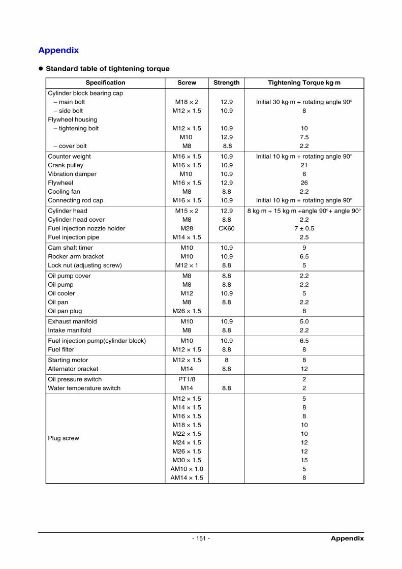
Appendix
Standard table of tightening torque
Specification Screw Strength Tightening Torque kg⋅m
Cylinder block bearing cap– main bolt
– side bolt
Flywheel housing – tightening bolt
– cover bolt
M18 × 2
M12 × 1.5
M12 × 1.5
M10
M8
12.9
10.9
10.9
12.9
8.8
Initial 30 kg⋅m + rotating angle 90°8
10
7.5
2.2
Counter weight
Crank pulleyVibration damper
Flywheel
Cooling fanConnecting rod cap
M16 × 1.5
M16 × 1.5M10
M16 × 1.5
M8M16 × 1.5
10.9
10.910.9
12.9
8.810.9
Initial 10 kg⋅m + rotating angle 90°216
26
2.2Initial 10 kg⋅m + rotating angle 90°
Cylinder headCylinder head cover
Fuel injection nozzle holder
Fuel injection pipe
M15 × 2M8
M28
M14 × 1.5
12.98.8
CK60
8 kg⋅m + 15 kg⋅m +angle 90°+ angle 90°2.2
7 ± 0.5
2.5
Cam shaft timer
Rocker arm bracket
Lock nut (adjusting screw)
M10
M10
M12 × 1
10.9
10.9
8.8
9
6.5
5
Oil pump cover
Oil pump Oil cooler
Oil pan
Oil pan plug
M8
M8M12
M8
M26 × 1.5
8.8
8.810.9
8.8
2.2
2.25
2.2
8
Exhaust manifold
Intake manifold
M10
M8
10.9
8.8
5.0
2.2
Fuel injection pump(cylinder block)
Fuel filter
M10
M12 × 1.5
10.9
8.8
6.5
8
Starting motor
Alternator bracket
M12 × 1.5
M14
8
8.8
8
12
Oil pressure switch
Water temperature switch
PT1/8
M14 8.8
2
2
Plug screw
M12 × 1.5
M14 × 1.5M16 × 1.5
M18 × 1.5
M22 × 1.5M24 × 1.5
M26 × 1.5
M30 × 1.5AM10 × 1.0
AM14 × 1.5
5
88
10
1012
12
155
8
Appendix- 151 -
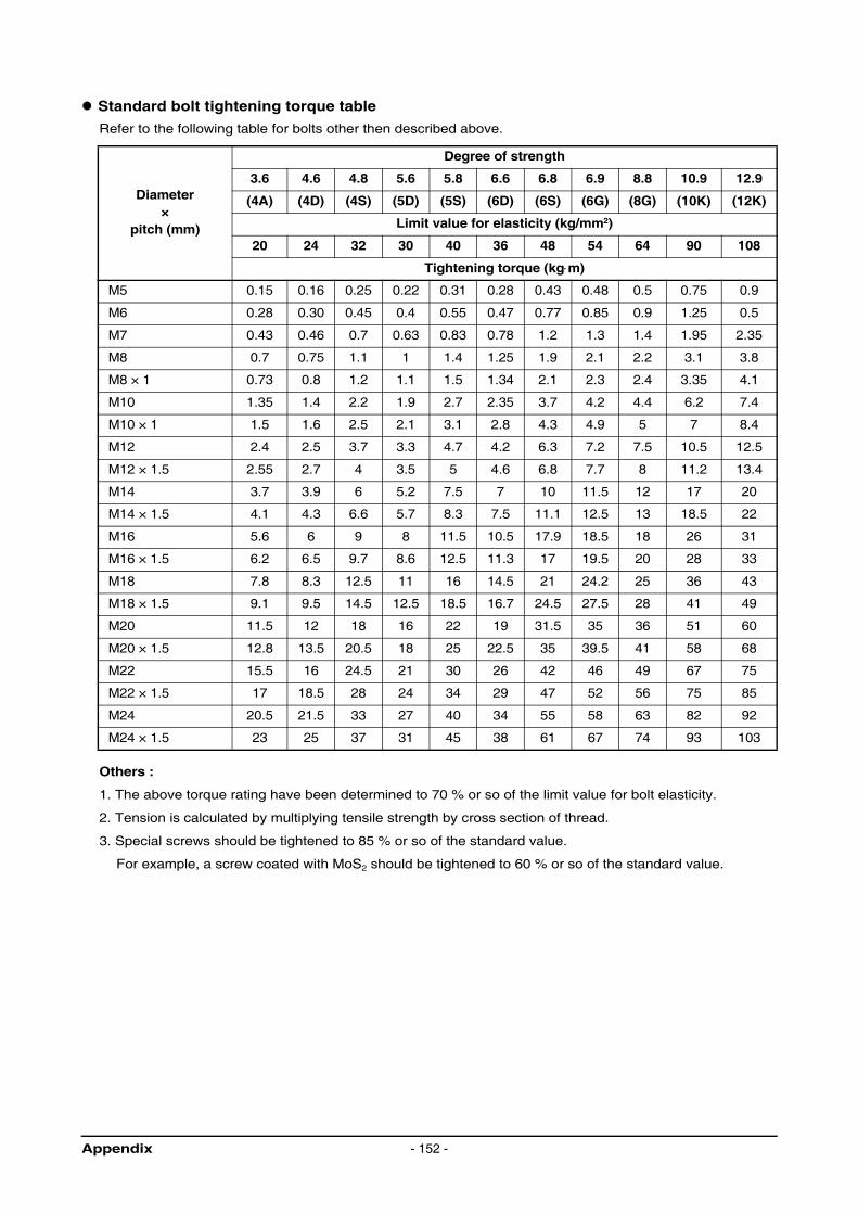
Standard bolt tightening torque table
Refer to the following table for bolts other then described above.
Others :
1. The above torque rating have been determined to 70 % or so of the limit value for bolt elasticity.
2. Tension is calculated by multiplying tensile strength by cross section of thread.
3. Special screws should be tightened to 85 % or so of the standard value.
For example, a screw coated with MoS2 should be tightened to 60 % or so of the standard value.
Diameter×
pitch (mm)
Degree of strength
3.6 4.6 4.8 5.6 5.8 6.6 6.8 6.9 8.8 10.9 12.9
(4A) (4D) (4S) (5D) (5S) (6D) (6S) (6G) (8G) (10K) (12K)
Limit value for elasticity (kg/mm2)
20 24 32 30 40 36 48 54 64 90 108
Tightening torque (kg⋅m)
M5 0.15 0.16 0.25 0.22 0.31 0.28 0.43 0.48 0.5 0.75 0.9
M6 0.28 0.30 0.45 0.4 0.55 0.47 0.77 0.85 0.9 1.25 0.5
M7 0.43 0.46 0.7 0.63 0.83 0.78 1.2 1.3 1.4 1.95 2.35
M8 0.7 0.75 1.1 1 1.4 1.25 1.9 2.1 2.2 3.1 3.8
M8 × 1 0.73 0.8 1.2 1.1 1.5 1.34 2.1 2.3 2.4 3.35 4.1
M10 1.35 1.4 2.2 1.9 2.7 2.35 3.7 4.2 4.4 6.2 7.4
M10 × 1 1.5 1.6 2.5 2.1 3.1 2.8 4.3 4.9 5 7 8.4
M12 2.4 2.5 3.7 3.3 4.7 4.2 6.3 7.2 7.5 10.5 12.5
M12 × 1.5 2.55 2.7 4 3.5 5 4.6 6.8 7.7 8 11.2 13.4
M14 3.7 3.9 6 5.2 7.5 7 10 11.5 12 17 20
M14 × 1.5 4.1 4.3 6.6 5.7 8.3 7.5 11.1 12.5 13 18.5 22
M16 5.6 6 9 8 11.5 10.5 17.9 18.5 18 26 31
M16 × 1.5 6.2 6.5 9.7 8.6 12.5 11.3 17 19.5 20 28 33
M18 7.8 8.3 12.5 11 16 14.5 21 24.2 25 36 43
M18 × 1.5 9.1 9.5 14.5 12.5 18.5 16.7 24.5 27.5 28 41 49
M20 11.5 12 18 16 22 19 31.5 35 36 51 60
M20 × 1.5 12.8 13.5 20.5 18 25 22.5 35 39.5 41 58 68
M22 15.5 16 24.5 21 30 26 42 46 49 67 75
M22 × 1.5 17 18.5 28 24 34 29 47 52 56 75 85
M24 20.5 21.5 33 27 40 34 55 58 63 82 92
M24 × 1.5 23 25 37 31 45 38 61 67 74 93 103
Appendix - 152 -
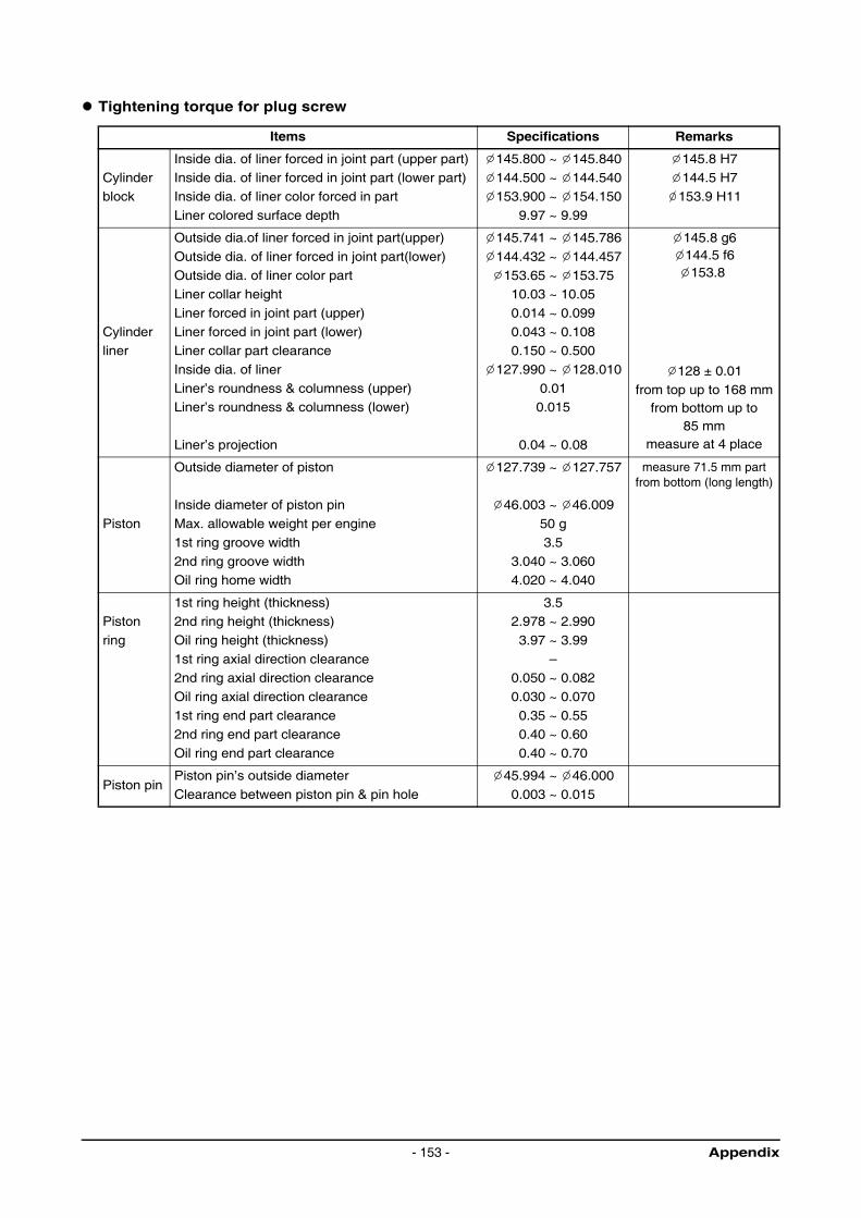
Tightening torque for plug screw
Items Specifications Remarks
Cylinder block
Inside dia. of liner forced in joint part (upper part)
Inside dia. of liner forced in joint part (lower part)Inside dia. of liner color forced in part
Liner colored surface depth
145.800 ~ 145.840
144.500 ~ 144.540153.900 ~ 154.150
9.97 ~ 9.99
145.8 H7
144.5 H7153.9 H11
Cylinder liner
Outside dia.of liner forced in joint part(upper)
Outside dia. of liner forced in joint part(lower)
Outside dia. of liner color partLiner collar height
Liner forced in joint part (upper)
Liner forced in joint part (lower)Liner collar part clearance
Inside dia. of liner
Liner’s roundness & columness (upper)Liner’s roundness & columness (lower)
Liner’s projection
145.741 ~ 145.786
144.432 ~ 144.457
153.65 ~ 153.7510.03 ~ 10.05
0.014 ~ 0.099
0.043 ~ 0.1080.150 ~ 0.500
127.990 ~ 128.010
0.010.015
0.04 ~ 0.08
145.8 g6144.5 f6153.8
128 ± 0.01from top up to 168 mm
from bottom up to 85 mm
measure at 4 place
Piston
Outside diameter of piston
Inside diameter of piston pin
Max. allowable weight per engine
1st ring groove width
2nd ring groove widthOil ring home width
127.739 ~ 127.757
46.003 ~ 46.009
50 g
3.5
3.040 ~ 3.0604.020 ~ 4.040
measure 71.5 mm part from bottom (long length)
Piston
ring
1st ring height (thickness)2nd ring height (thickness)
Oil ring height (thickness)
1st ring axial direction clearance2nd ring axial direction clearance
Oil ring axial direction clearance
1st ring end part clearance2nd ring end part clearance
Oil ring end part clearance
3.52.978 ~ 2.990
3.97 ~ 3.99
–0.050 ~ 0.082
0.030 ~ 0.070
0.35 ~ 0.550.40 ~ 0.60
0.40 ~ 0.70
Piston pinPiston pin’s outside diameter
Clearance between piston pin & pin hole
45.994 ~ 46.000
0.003 ~ 0.015
Appendix- 153 -
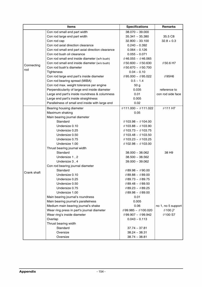
Items Specifications Remarks
Connecting
rod
Con rod small end part width
Con rod large end part width
Con rod capCon rod axial direction clearance
Con rod small end part axial direction clearance
Con rod bush oil clearanceCon rod small end inside diameter (w/h bush)
Con rod small end inside diameter (w/o bush)
Con rod bush’s diameterTighteness
Con rod large end part’s inside diameter
Con rod bearing spread (MIBA)Con rod max. weight tolerance per engine
Perpendicularity of large end inside diameter
Large end part’s inside roundness & columnessLarge end part’s inside straightness
Parallelness of small end inside with large end
38.070 ~ 39.000
35.341 ~ 35.380
32.800 ~ 33.1000.240 ~ 0.392
0.064 ~ 0.126
0.055 ~ 0.07146.055 ~ 46.065
50.600 ~ 50.630
50.670 ~ 50.7000.04 ~ 0.10
95.000 ~ 95.022
0.5 ~ 1.450 g
0.035
0.010.005
0.02
35.5 C8
32.8 + 0.3
50.6 H7
95H6
reference to
con rod side face
Crank shaft
Bearing housing diameter
Maximum shaking
Main bearing journal diameterStandard
Undersize 0.10
Undersize 0.25
Undersize 0.50Undersize 0.75
Undersize 1.00
Thrust bearing journal widthStandard
Undersize 1 , 2
Undersize 3 , 4Con rod bearing journal diameter
Standard
Undersize 0.10Undersize 0.25
Undersize 0.50
Undersize 0.75Undersize 1.00
Main bearing journal’s roundness
Main bearing journal’s parallelnessMedium main bearing journal’s shake
Wear ring press in part’s journal diameter
Wear ring’s inside diameterOverlap
Thrust bearing width
Standard Oversize
Oversize
111.000 ~ 111.022
0.05
103.98 ~ 104.00
103.88 ~ 103.90
103.73 ~ 103.75
103.48 ~ 103.50103.23 ~ 103.25
102.98 ~ 103.00
38.000 ~ 38.062
38.500 ~ 38.562
39.000 ~ 39.062
89.98 ~ 90.00
89.88 ~ 89.0089.73 ~ 89.75
89.48 ~ 89.50
89.23 ~ 89.2589.98 ~ 89.00
0.01
0.0050.06
99.985 ~ 100.020
99.907 ~ 99.9420.043 ~ 0.113
37.74 ~ 37.8138.24 ~ 38.31
38.74 ~ 38.81
111 H7
38 H9
no 1, no 5 support
100 j7
100 S7
Appendix - 154 -
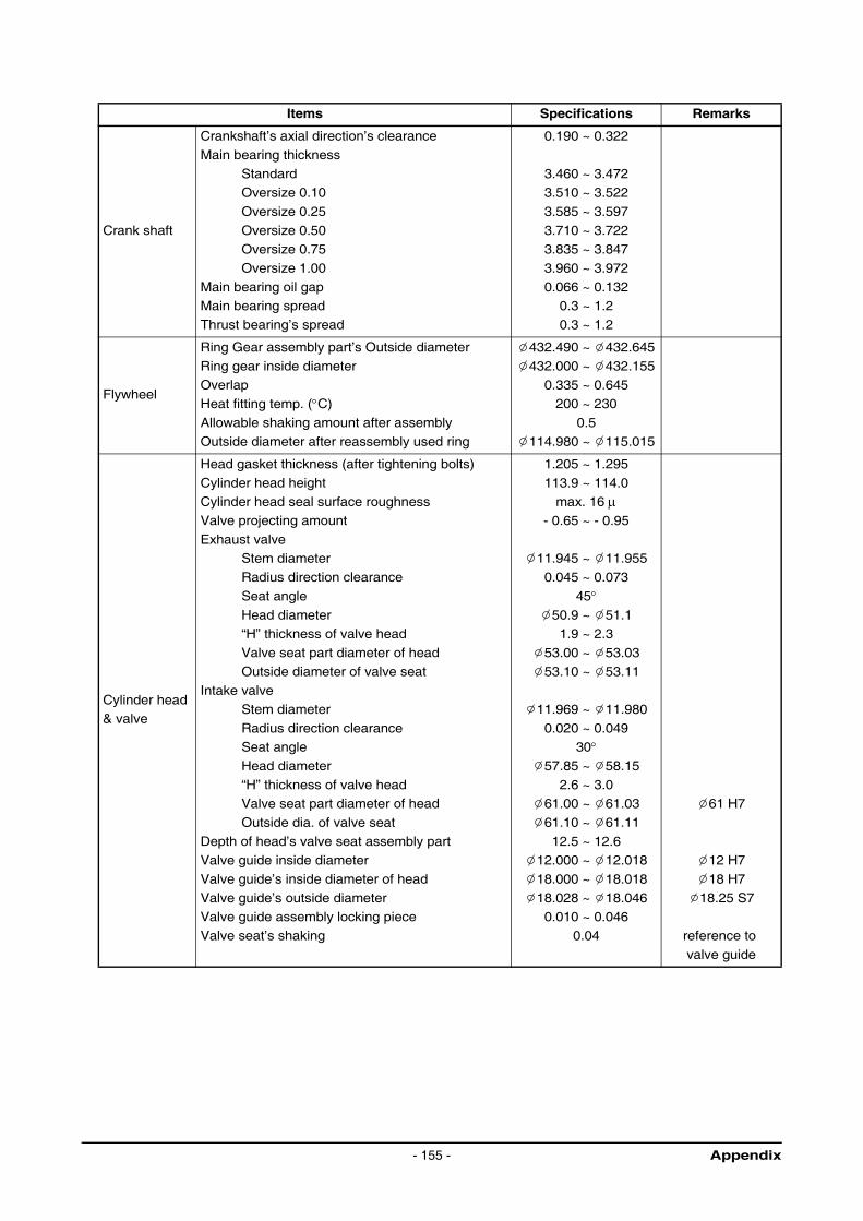
Items Specifications Remarks
Crank shaft
Crankshaft’s axial direction’s clearance
Main bearing thickness
StandardOversize 0.10
Oversize 0.25
Oversize 0.50Oversize 0.75
Oversize 1.00
Main bearing oil gapMain bearing spread
Thrust bearing’s spread
0.190 ~ 0.322
3.460 ~ 3.4723.510 ~ 3.522
3.585 ~ 3.597
3.710 ~ 3.7223.835 ~ 3.847
3.960 ~ 3.972
0.066 ~ 0.1320.3 ~ 1.2
0.3 ~ 1.2
Flywheel
Ring Gear assembly part’s Outside diameter
Ring gear inside diameter
OverlapHeat fitting temp. (°C)
Allowable shaking amount after assembly
Outside diameter after reassembly used ring
432.490 ~ 432.645
432.000 ~ 432.155
0.335 ~ 0.645200 ~ 230
0.5
114.980 ~ 115.015
Cylinder head& valve
Head gasket thickness (after tightening bolts)
Cylinder head height Cylinder head seal surface roughness
Valve projecting amount
Exhaust valveStem diameter
Radius direction clearance
Seat angle
Head diameter“H” thickness of valve head
Valve seat part diameter of head
Outside diameter of valve seatIntake valve
Stem diameter
Radius direction clearanceSeat angle
Head diameter
“H” thickness of valve headValve seat part diameter of head
Outside dia. of valve seat
Depth of head’s valve seat assembly partValve guide inside diameter
Valve guide’s inside diameter of head
Valve guide’s outside diameterValve guide assembly locking piece
Valve seat’s shaking
1.205 ~ 1.295
113.9 ~ 114.0max. 16 µ
- 0.65 ~ - 0.95
11.945 ~ 11.955
0.045 ~ 0.073
45°50.9 ~ 51.11.9 ~ 2.3
53.00 ~ 53.03
53.10 ~ 53.11
11.969 ~ 11.980
0.020 ~ 0.04930°
57.85 ~ 58.15
2.6 ~ 3.061.00 ~ 61.03
61.10 ~ 61.11
12.5 ~ 12.612.000 ~ 12.018
18.000 ~ 18.018
18.028 ~ 18.0460.010 ~ 0.046
0.04
61 H7
12 H7
18 H7
18.25 S7
reference to
valve guide
Appendix- 155 -
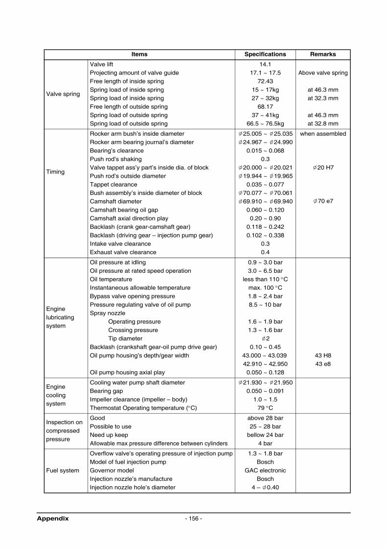
Items Specifications Remarks
Valve spring
Valve liftProjecting amount of valve guide
Free length of inside spring
Spring load of inside springSpring load of inside spring
Free length of outside spring
Spring load of outside springSpring load of outside spring
14.117.1 ~ 17.5
72.43
15 ~ 17kg27 ~ 32kg
68.17
37 ~ 41kg66.5 ~ 76.5kg
Above valve spring
at 46.3 mmat 32.3 mm
at 46.3 mmat 32.8 mm
Timing
Rocker arm bush’s inside diameterRocker arm bearing journal’s diameter
Bearing’s clearance
Push rod’s shakingValve tappet ass’y part’s inside dia. of block
Push rod’s outside diameter
Tappet clearanceBush assembly’s inside diameter of block
Camshaft diameter
Camshaft bearing oil gapCamshaft axial direction play
Backlash (crank gear-camshaft gear)
Backlash (driving gear – injection pump gear)Intake valve clearance
Exhaust valve clearance
25.005 ~ 25.03524.967 ~ 24.990
0.015 ~ 0.068
0.320.000 ~ 20.021
19.944 ~ 19.965
0.035 ~ 0.07770.077 ~ 70.061
69.910 ~ 69.940
0.060 ~ 0.1200.20 ~ 0.90
0.118 ~ 0.242
0.102 ~ 0.3380.3
0.4
when assembled
20 H7
70 e7
Engine
lubricating system
Oil pressure at idling
Oil pressure at rated speed operation
Oil temperatureInstantaneous allowable temperature
Bypass valve opening pressure
Pressure regulating valve of oil pump Spray nozzle
Operating pressure
Crossing pressureTip diameter
Backlash (crankshaft gear-oil pump drive gear)
Oil pump housing’s depth/gear width
Oil pump housing axial play
0.9 ~ 3.0 bar
3.0 ~ 6.5 bar
less than 110 °Cmax. 100 °C1.8 ~ 2.4 bar
8.5 ~ 10 bar
1.6 ~ 1.9 bar
1.3 ~ 1.6 bar2
0.10 ~ 0.45
43.000 ~ 43.039
42.910 ~ 42.9500.050 ~ 0.128
43 H8
43 e8
Engine
cooling system
Cooling water pump shaft diameterBearing gap
Impeller clearance (impeller – body)
Thermostat Operating temperature (°C)
21.930 ~ 21.9500.050 ~ 0.091
1.0 ~ 1.5
79 °C
Inspection on
compressed
pressure
Good
Possible to useNeed up keep
Allowable max pressure difference between cylinders
above 28 bar
25 ~ 28 barbellow 24 bar
4 bar
Fuel system
Overflow valve’s operating pressure of injection pump
Model of fuel injection pump
Governor modelInjection nozzle’s manufacture
Injection nozzle hole’s diameter
1.3 ~ 1.8 bar
Bosch
GAC electronicBosch
4 – 0.40
Appendix - 156 -
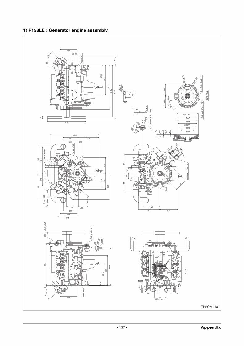
1) P158LE : Generator engine assembly
EH5OM013
Appendix- 157 -

2) P180LE : Generator engine assembly
EH5OM014
Appendix - 158 -
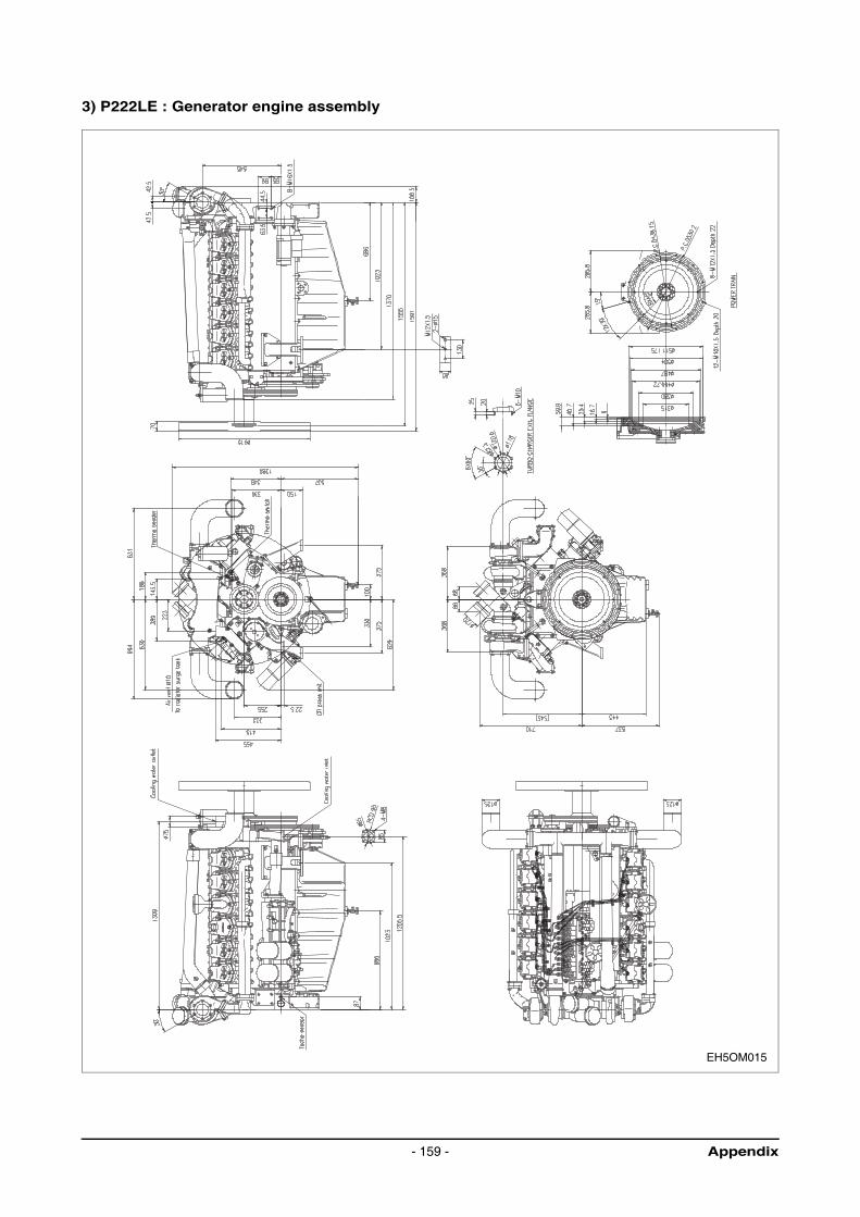
3) P222LE : Generator engine assembly
EH5OM015
Appendix- 159 -
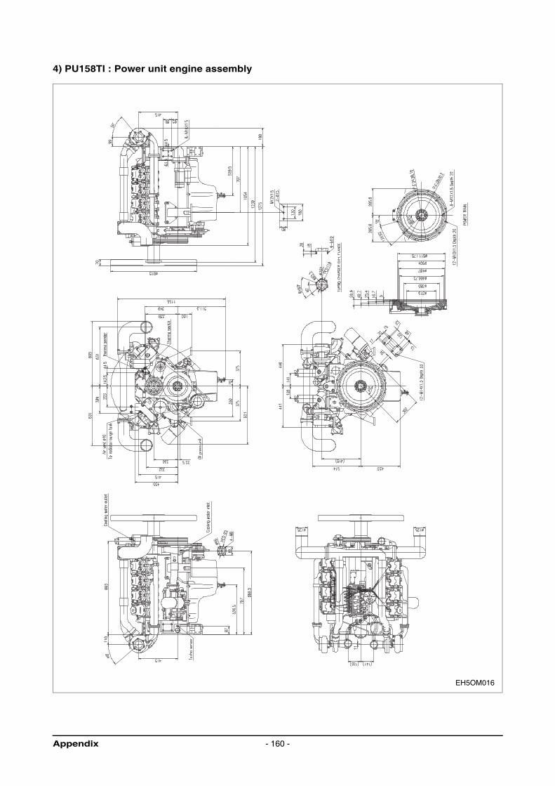
4) PU158TI : Power unit engine assembly
EH5OM016
Appendix - 160 -

5) PU180TI : Power unit engine assembly
EH5OM017
Appendix- 161 -
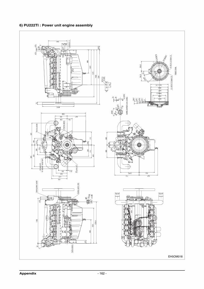
6) PU222TI : Power unit engine assembly
EH5OM018
Appendix - 162 -