67 - kingbright usa led components manufacturers notes.pdf · 67 73 77 91 93 94 98 66. technical...
TRANSCRIPT


67737791939498
66
www.KingbrightUSA.com
TECHNICAL NOTES
67
13"(for 32mm width tape)
7"(for 8mm width tape) 7"(for 12mm width tape)
13"(for 24mm width tape)
13"(for 44mm width tape) 15”(for 16mm width tape)
Reel Dimensions Part Number Reel
Dimensions Part Number Reel Dimensions Part Number
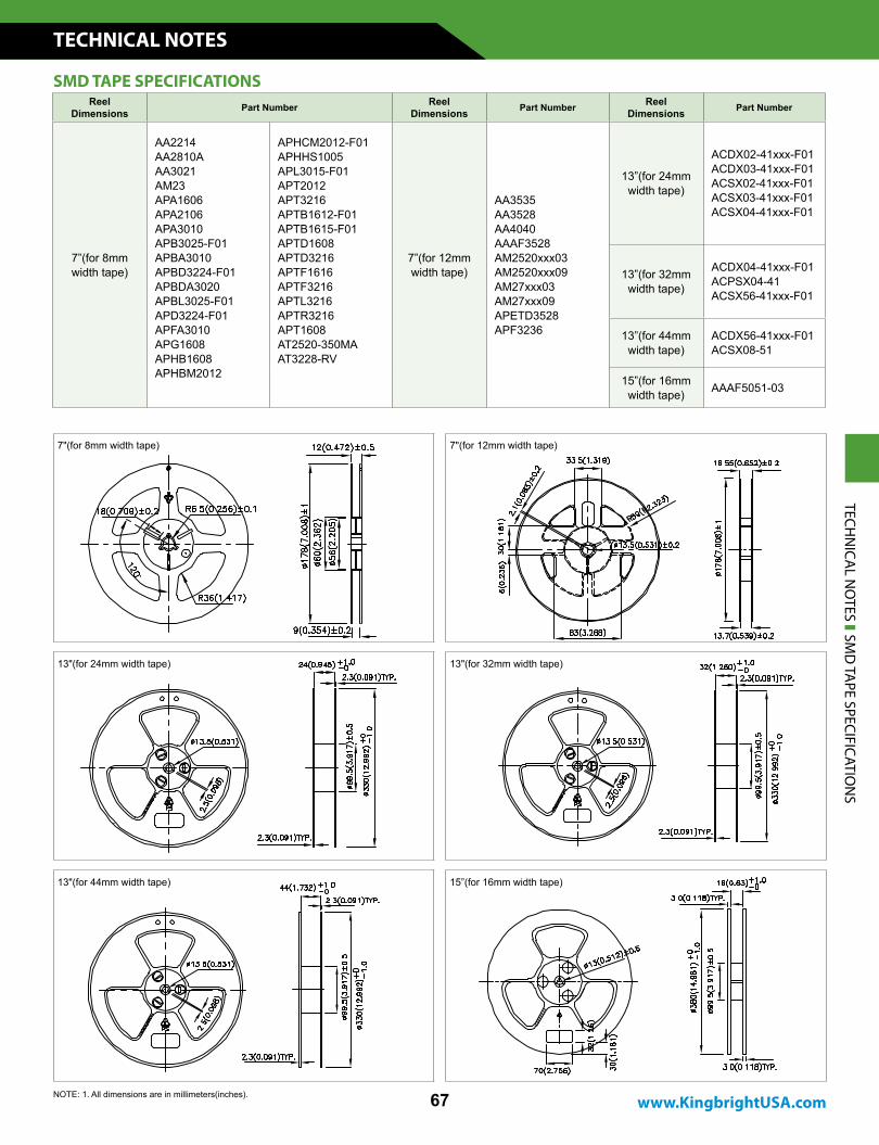
7”(for 8mm width tape)
AA2214AA2810AAA3021AM23APA1606APA2106APA3010APB3025-F01APBA3010APBD3224-F01APBDA3020APBL3025-F01APD3224-F01APFA3010APG1608APHB1608APHBM2012
APHCM2012-F01APHHS1005APL3015-F01APT2012APT3216APTB1612-F01APTB1615-F01APTD1608APTD3216APTF1616APTF3216APTL3216APTR3216APT1608AT2520-350MAAT3228-RV
7”(for 12mm width tape)
AA3535AA3528AA4040AAAF3528AM2520xxx03AM2520xxx09AM27xxx03AM27xxx09APETD3528APF3236
13”(for 24mm width tape)
ACDX02-41xxx-F01ACDX03-41xxx-F01ACSX02-41xxx-F01ACSX03-41xxx-F01ACSX04-41xxx-F01
13”(for 32mm width tape)
ACDX04-41xxx-F01ACPSX04-41ACSX56-41xxx-F01
13”(for 44mm width tape)
ACDX56-41xxx-F01ACSX08-51
15”(for 16mm width tape) AAAF5051-03
SMD TAPE SPECIFICATIONS
TECHN
ICAL N
OTES SM
D TA
PE SPECIFICATION
S
NOTE: 1. All dimensions are in millimeters(inches).
TECHNICAL NOTES
68
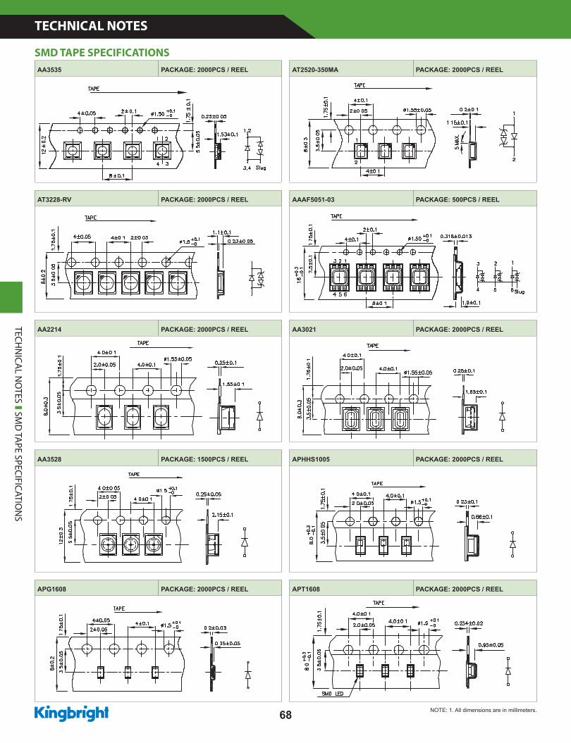
AA3535 PACKAGE: 2000PCS / REEL AT2520-350MA PACKAGE: 2000PCS / REEL
AT3228-RV PACKAGE: 2000PCS / REEL AAAF5051-03 PACKAGE: 500PCS / REEL
AA2214 PACKAGE: 2000PCS / REEL AA3021 PACKAGE: 2000PCS / REEL
AA3528 PACKAGE: 1500PCS / REEL APHHS1005 PACKAGE: 2000PCS / REEL
APG1608 PACKAGE: 2000PCS / REEL APT1608 PACKAGE: 2000PCS / REEL
TECHN
ICAL N
OTES SM
D TA
PE SPECIFICATION
S
SMD TAPE SPECIFICATIONS
NOTE: 1. All dimensions are in millimeters.
www.KingbrightUSA.com
TECHNICAL NOTES
69
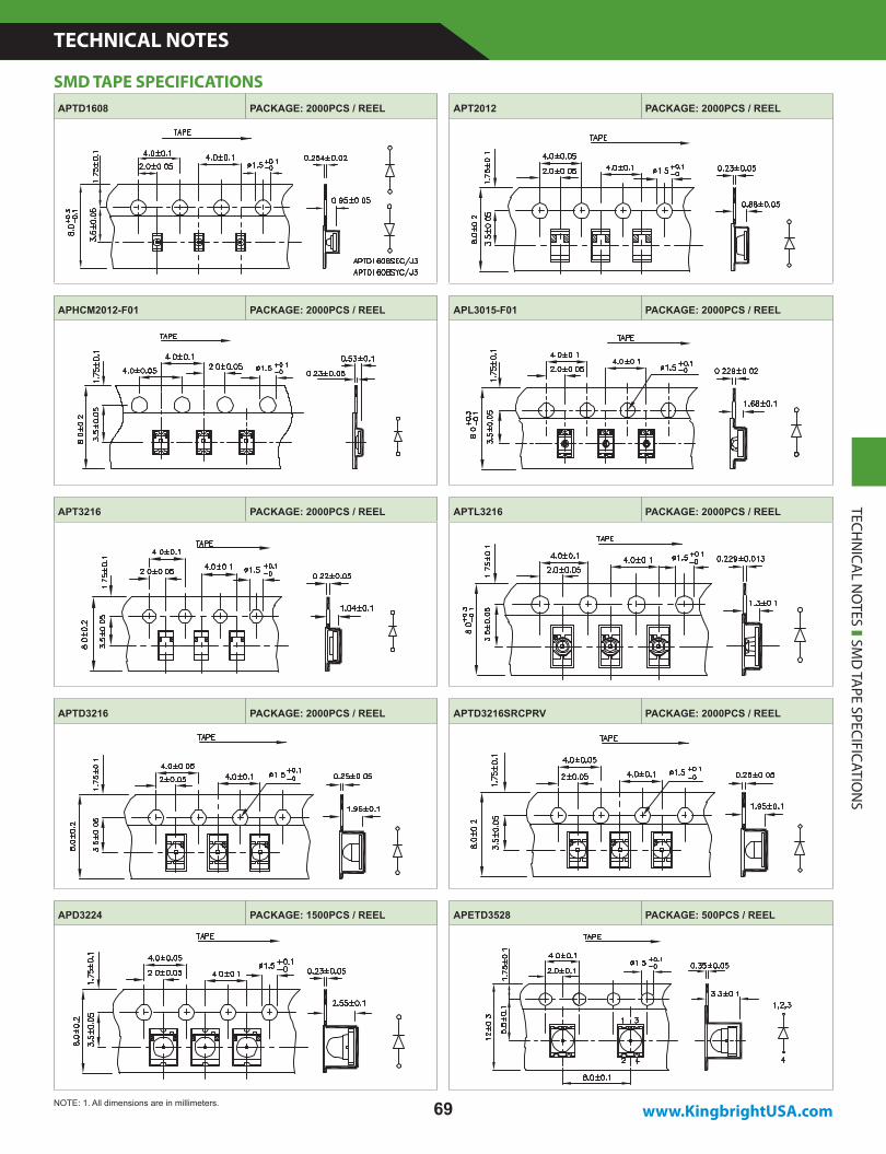
APTD1608 PACKAGE: 2000PCS / REEL APT2012 PACKAGE: 2000PCS / REEL
APHCM2012-F01 PACKAGE: 2000PCS / REEL APL3015-F01 PACKAGE: 2000PCS / REEL
APT3216 PACKAGE: 2000PCS / REEL APTL3216 PACKAGE: 2000PCS / REEL
APTD3216 PACKAGE: 2000PCS / REEL APTD3216SRCPRV PACKAGE: 2000PCS / REEL
APD3224 PACKAGE: 1500PCS / REEL APETD3528 PACKAGE: 500PCS / REEL
TECHN
ICAL N
OTES SM
D TA
PE SPECIFICATION
S
SMD TAPE SPECIFICATIONS
NOTE: 1. All dimensions are in millimeters.
TECHNICAL NOTES
70
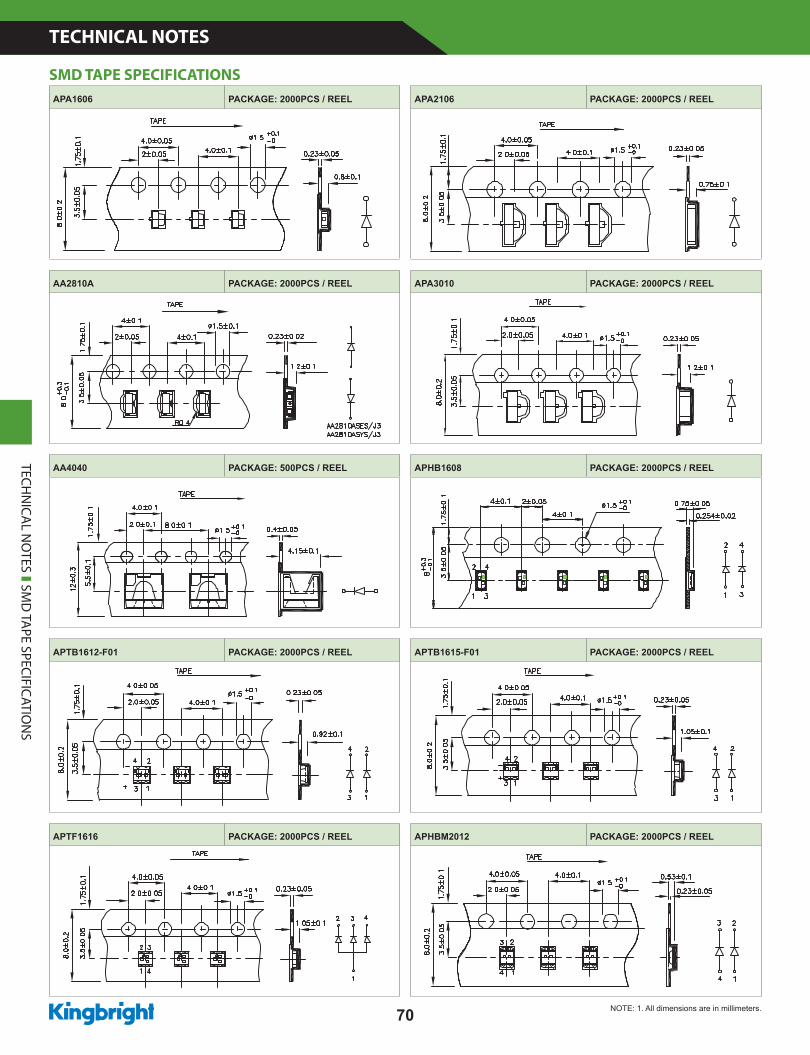
APA1606 PACKAGE: 2000PCS / REEL APA2106 PACKAGE: 2000PCS / REEL
AA2810A PACKAGE: 2000PCS / REEL APA3010 PACKAGE: 2000PCS / REEL
AA4040 PACKAGE: 500PCS / REEL APHB1608 PACKAGE: 2000PCS / REEL
APTB1612-F01 PACKAGE: 2000PCS / REEL APTB1615-F01 PACKAGE: 2000PCS / REEL
APTF1616 PACKAGE: 2000PCS / REEL APHBM2012 PACKAGE: 2000PCS / REEL
TECHN
ICAL N
OTES SM
D TA
PE SPECIFICATION
S
SMD TAPE SPECIFICATIONS
NOTE: 1. All dimensions are in millimeters.
www.KingbrightUSA.com
TECHNICAL NOTES
71
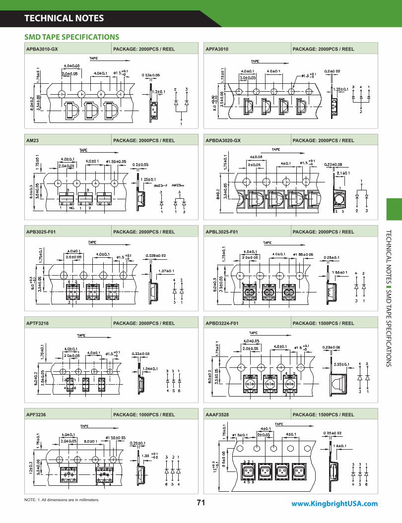
APBA3010-GX PACKAGE: 2000PCS / REEL APFA3010 PACKAGE: 2000PCS / REEL
AM23 PACKAGE: 2000PCS / REEL APBDA3020-GX PACKAGE: 2000PCS / REEL
APB3025-F01 PACKAGE: 2000PCS / REEL APBL3025-F01 PACKAGE: 2000PCS / REEL
APTF3216 PACKAGE: 2000PCS / REEL APBD3224-F01 PACKAGE: 1500PCS / REEL
APF3236 PACKAGE: 1000PCS / REEL AAAF3528 PACKAGE: 1500PCS / REEL
TECHN
ICAL N
OTES SM
D TA
PE SPECIFICATION
S
SMD TAPE SPECIFICATIONS
NOTE: 1. All dimensions are in millimeters.
TECHNICAL NOTES
72
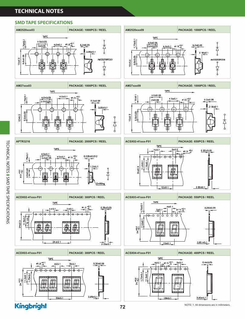
AM2520xxx03 PACKAGE: 1000PCS / REEL AM2520xxx09 PACKAGE: 1000PCS / REEL
AM27xxx03 PACKAGE: 1000PCS / REEL AM27xxx09 PACKAGE: 1000PCS / REEL
APTR3216 PACKAGE: 2000PCS / REEL ACSX02-41xxx-F01 PACKAGE: 650PCS / REEL
ACDX02-41xxx-F01 PACKAGE: 300PCS / REEL ACSX03-41xxx-F01 PACKAGE: 550PCS / REEL
ACDX03-41xxx-F01 PACKAGE: 300PCS / REEL ACSX04-41xxx-F01 PACKAGE: 400PCS / REEL
TECHN
ICAL N
OTES SM
D TA
PE SPECIFICATION
S
SMD TAPE SPECIFICATIONS
NOTE: 1. All dimensions are in millimeters.
www.KingbrightUSA.com
TECHNICAL NOTES
73
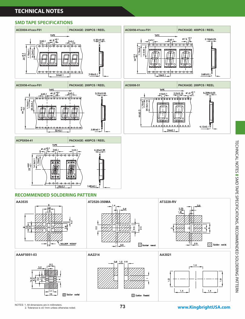
ACSX56-41xxx-F01 PACKAGE: 400PCS / REEL
ACSX08-51 PACKAGE: 200PCS / REEL
ACSX56-41xxx-F01 PACKAGE: 400PCS / REEL
ACSX08-51 PACKAGE: 200PCS / REEL
ACDX04-41xxx-F01 PACKAGE: 250PCS / REEL
ACDX56-41xxx-F01 PACKAGE: 200PCS / REEL
ACPSX04-41 PACKAGE: 400PCS / REEL TECHN
ICAL N
OTES SM
D TA
PE SPECIFICATION
S, RECOM
MEN
DED
SOLD
ERING
PATTERN
SMD TAPE SPECIFICATIONS
AA3535 AT2520-350MA AT3228-RV
AAAF5051-03 AA2214 AA3021
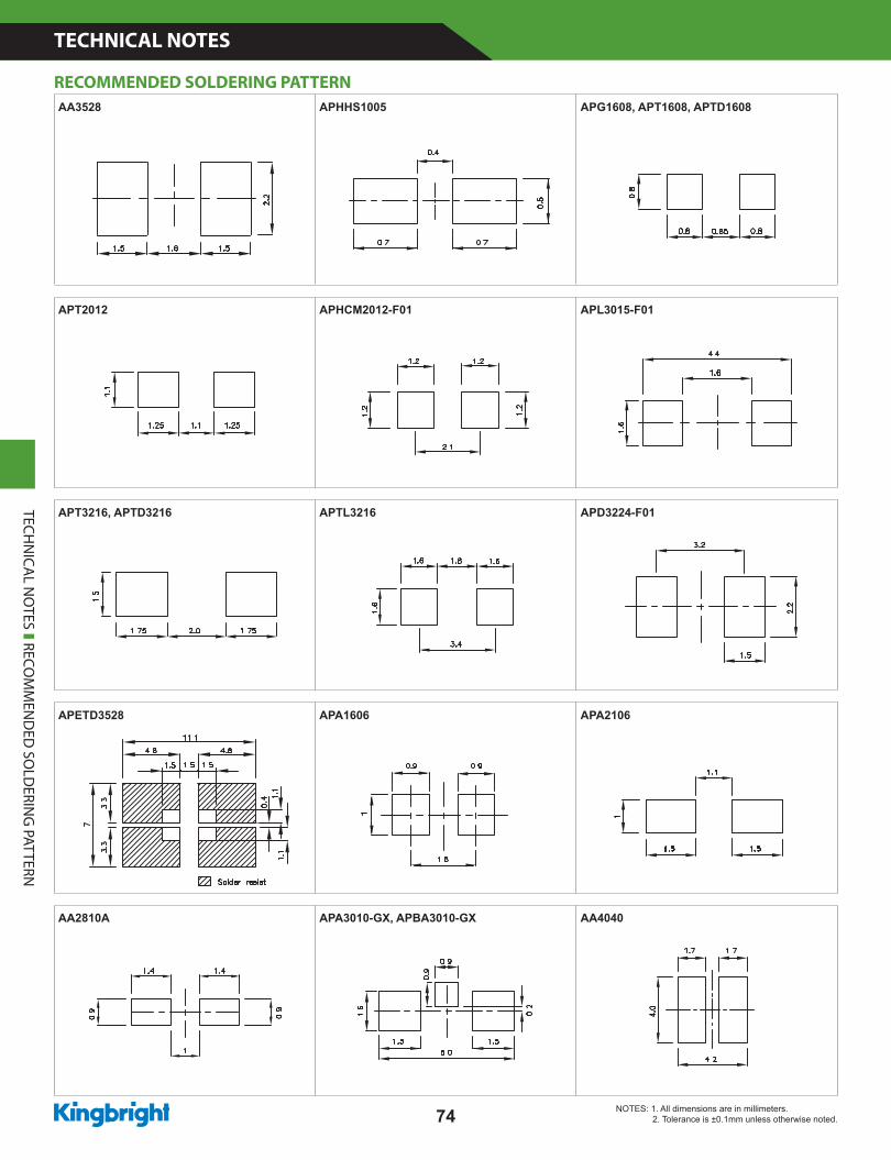
RECOMMENDED SOLDERING PATTERN
NOTES: 1. All dimensions are in millimeters. 2. Tolerance is ±0.1mm unless otherwise noted.
TECHNICAL NOTES
74
AA3528 APHHS1005 APG1608, APT1608, APTD1608
APT2012 APHCM2012-F01 APL3015-F01
APT3216, APTD3216 APTL3216 APD3224-F01
APETD3528 APA1606 APA2106
AA2810A APA3010-GX, APBA3010-GX AA4040
RECOMMENDED SOLDERING PATTERN
TECHN
ICAL N
OTES RECO
MM
END
ED SO
LDERIN
G PATTERN
NOTES: 1. All dimensions are in millimeters. 2. Tolerance is ±0.1mm unless otherwise noted.
www.KingbrightUSA.com
TECHNICAL NOTES
75
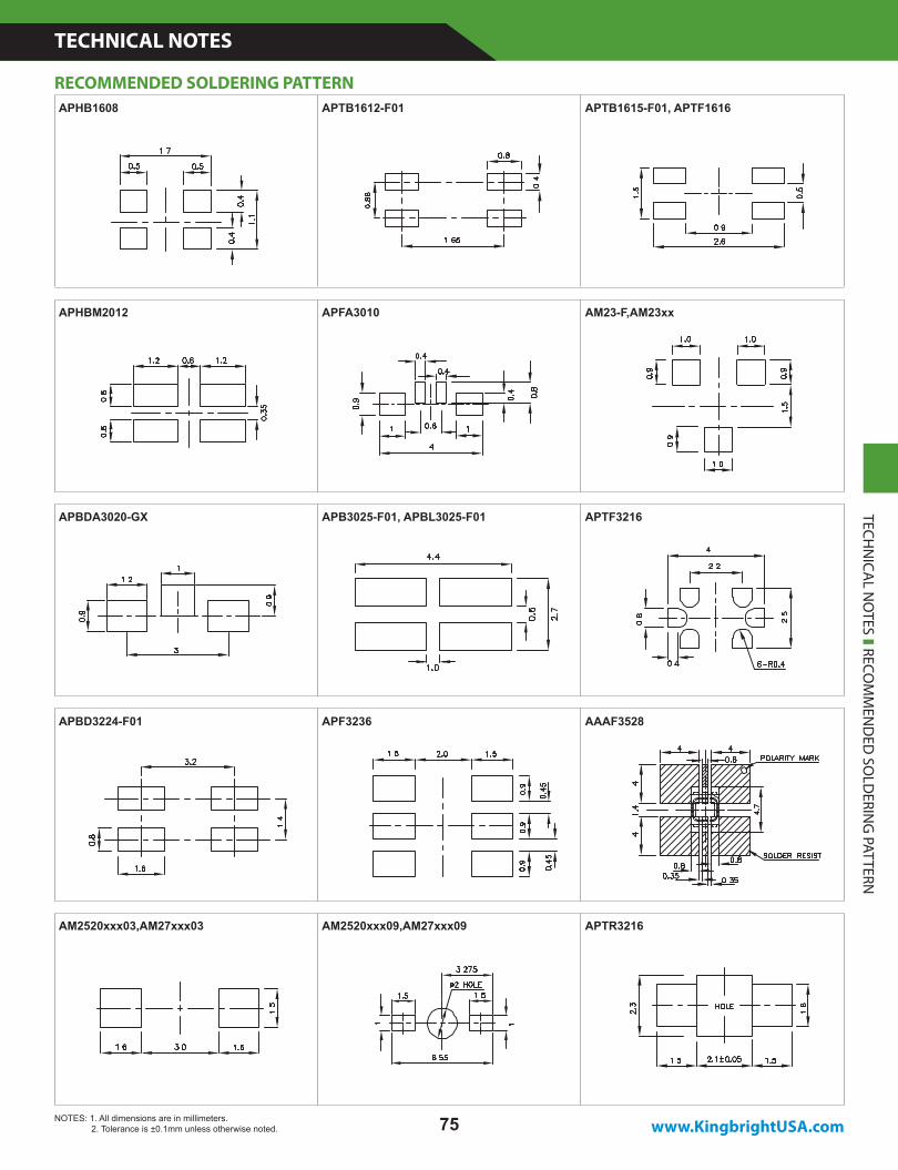
APHB1608 APTB1612-F01 APTB1615-F01, APTF1616
APHBM2012 APFA3010 AM23-F,AM23xx
APBDA3020-GX APB3025-F01, APBL3025-F01 APTF3216 TECHN
ICAL N
OTES RECO
MM
END
ED SO
LDERIN
G PATTERN
RECOMMENDED SOLDERING PATTERN
NOTES: 1. All dimensions are in millimeters. 2. Tolerance is ±0.1mm unless otherwise noted.
APBD3224-F01 APF3236 AAAF3528
AM2520xxx03,AM27xxx03 AM2520xxx09,AM27xxx09 APTR3216
TECHNICAL NOTES
76
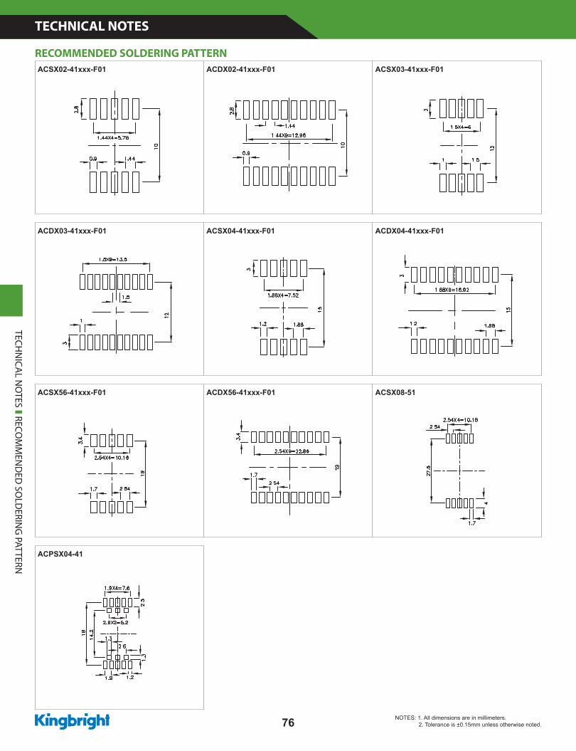
ACSX02-41xxx-F01 ACDX02-41xxx-F01 ACSX03-41xxx-F01
ACDX03-41xxx-F01 ACSX04-41xxx-F01 ACDX04-41xxx-F01
ACSX56-41xxx-F01 ACDX56-41xxx-F01 ACSX08-51
ACPSX04-41TECH
NICA
L NO
TES RECOM
MEN
DED
SOLD
ERING
PATTERN
RECOMMENDED SOLDERING PATTERN
NOTES: 1. All dimensions are in millimeters. 2. Tolerance is ±0.15mm unless otherwise noted.
www.KingbrightUSA.com
TECHNICAL NOTES
77
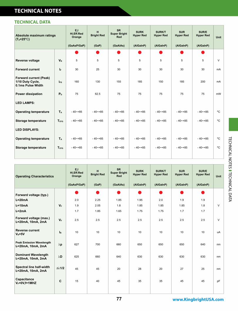
Absolute maximum ratings (TA=25°C)
E,IHi.Eff.Red
Orange
HBright Red
SRSuper Bright
Red
SURKHyper Red
SURK/THyper Red
SURHyper Red
SUR/EHyper Red
Unit
(GaAsP/GaP) (GaP) (GaAlAs) (AlGaInP) (AlGaInP) (AlGaInP) (AlGaInP)
Reverse voltage VR 5 5 5 5 5 5 5 V
Forward current IF 30 25 30 30 30 30 30 mA
Forward current (Peak) 1/10 Duty Cycle,0.1ms Pulse Width
iFS 160 130 155 185 150 185 200 mA
Power dissipation PD 75 62.5 75 75 75 75 75 mW
LED LAMPS:
Operating temperature TA - 40~+85 - 40~+85 - 40~+85 - 40~+85 - 40~+85 - 40~+85 - 40~+85 °C
Storage temperature TSTG - 40~+85 - 40~+85 - 40~+85 - 40~+85 - 40~+85 - 40~+85 - 40~+85 °C
LED DISPLAYS:
Operating temperature TA - 40~+85 - 40~+85 - 40~+85 - 40~+85 - 40~+85 - 40~+85 - 40~+85 °C
Storage temperature TSTG - 40~+85 - 40~+85 - 40~+85 - 40~+85 - 40~+85 - 40~+85 - 40~+85 °C
Operating Characteristics
E,IHi.Eff.Red
Orange
HBright Red
SRSuper Bright
Red
SURKHyper Red
SURK/THyper Red
SURHyper Red
SUR/EHyper Red
Unit
(GaAsP/GaP) (GaP) (GaAlAs) (AlGaInP) (AlGaInP) (AlGaInP) (AlGaInP)
Forward voltage (typ.)
IF=20mA
VF
2.0 2.25 1.85 1.95 2.0 1.9 1.9
VIF=10mA 1.9 2.05 1.8 1.85 1.85 1.85 1.8
IF=2mA 1.7 1.85 1.65 1.75 1.75 1.7 1.7
Forward voltage (max.)IF=20mA, 10mA, 2mA VF 2.5 2.5 2.5 2.5 2.5 2.5 2.5 V
Reverse currentVR=5V IR 10 10 10 10 10 10 10 uA
Peak Emission WavelengthIF=20mA, 10mA, 2mA lp 627 700 660 650 650 650 640 nm
Dominant Wavelength IF=20mA, 10mA, 2mA lD 625 660 640 630 630 630 630 nm
Spectral line half-widthIF=20mA, 10mA, 2mA
Dl1/2 45 45 20 28 20 27 25 nm
CapacitanceVF=0V,f=1MHZ C 15 40 45 35 35 45 45 pF
TECHNICAL DATA
TECHN
ICAL N
OTES TECH
NICA
L DATA
TECHNICAL NOTES
78
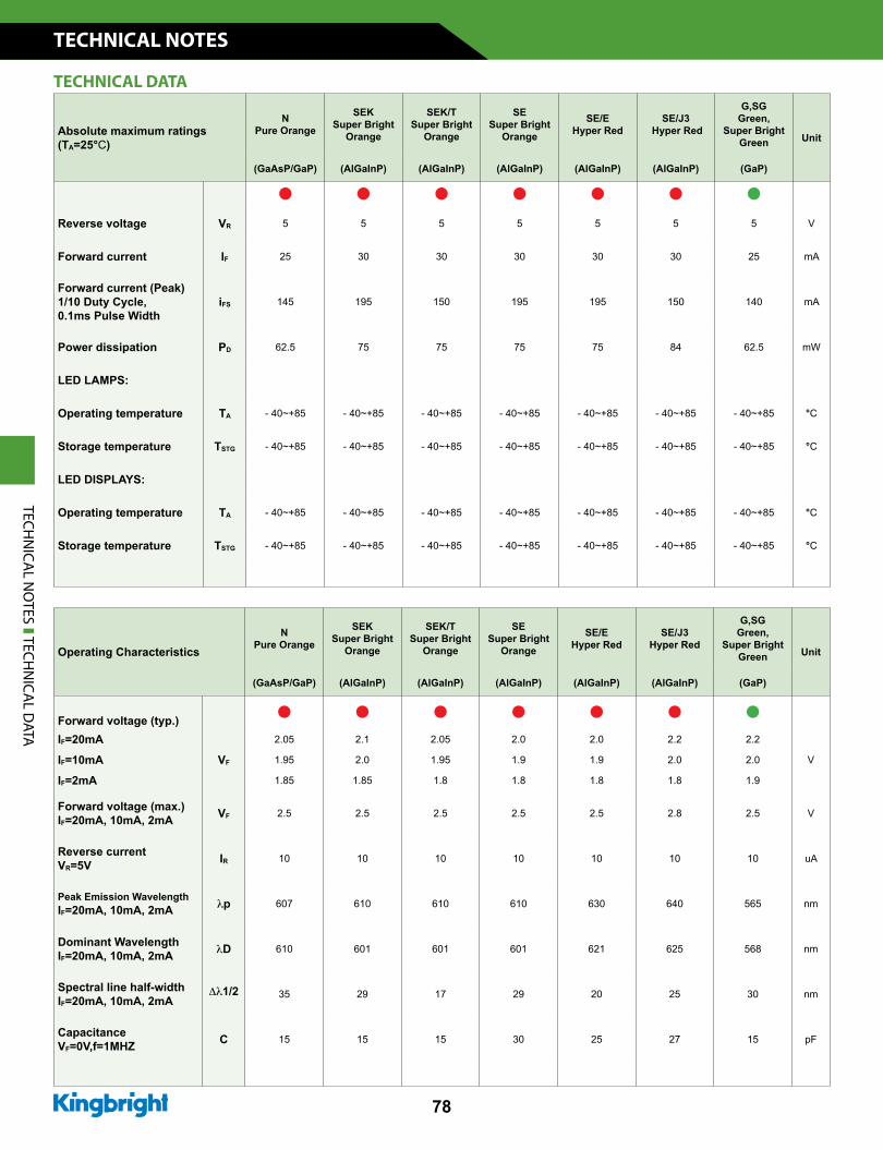
Absolute maximum ratings (TA=25°C)
NPure Orange
SEKSuper Bright
Orange
SEK/TSuper Bright
Orange
SESuper Bright
Orange
SE/EHyper Red
SE/J3 Hyper Red
G,SGGreen,
Super Bright Green Unit
(GaAsP/GaP) (AlGaInP) (AlGaInP) (AlGaInP) (AlGaInP) (AlGaInP) (GaP)
Reverse voltage VR 5 5 5 5 5 5 5 V
Forward current IF 25 30 30 30 30 30 25 mA
Forward current (Peak) 1/10 Duty Cycle,0.1ms Pulse Width
iFS 145 195 150 195 195 150 140 mA
Power dissipation PD 62.5 75 75 75 75 84 62.5 mW
LED LAMPS:
Operating temperature TA - 40~+85 - 40~+85 - 40~+85 - 40~+85 - 40~+85 - 40~+85 - 40~+85 °C
Storage temperature TSTG - 40~+85 - 40~+85 - 40~+85 - 40~+85 - 40~+85 - 40~+85 - 40~+85 °C
LED DISPLAYS:
Operating temperature TA - 40~+85 - 40~+85 - 40~+85 - 40~+85 - 40~+85 - 40~+85 - 40~+85 °C
Storage temperature TSTG - 40~+85 - 40~+85 - 40~+85 - 40~+85 - 40~+85 - 40~+85 - 40~+85 °C
Operating CharacteristicsN
Pure Orange
SEKSuper Bright
Orange
SEK/T Super Bright
Orange
SESuper Bright
Orange
SE/EHyper Red
SE/J3Hyper Red
G,SGGreen,
Super Bright Green Unit
(GaAsP/GaP) (AlGaInP) (AlGaInP) (AlGaInP) (AlGaInP) (AlGaInP) (GaP)
Forward voltage (typ.)IF=20mA
VF
2.05 2.1 2.05 2.0 2.0 2.2 2.2
VIF=10mA 1.95 2.0 1.95 1.9 1.9 2.0 2.0
IF=2mA 1.85 1.85 1.8 1.8 1.8 1.8 1.9
Forward voltage (max.)IF=20mA, 10mA, 2mA VF 2.5 2.5 2.5 2.5 2.5 2.8 2.5 V
Reverse currentVR=5V IR 10 10 10 10 10 10 10 uA
Peak Emission WavelengthIF=20mA, 10mA, 2mA lp 607 610 610 610 630 640 565 nm
Dominant Wavelength IF=20mA, 10mA, 2mA lD 610 601 601 601 621 625 568 nm
Spectral line half-widthIF=20mA, 10mA, 2mA
Dl1/2 35 29 17 29 20 25 30 nm
CapacitanceVF=0V,f=1MHZ C 15 15 15 30 25 27 15 pF
TECHNICAL DATA
TECHN
ICAL N
OTES TECH
NICA
L DATA
www.KingbrightUSA.com
TECHNICAL NOTES
79
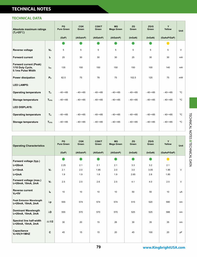
Absolute maximum ratings (TA=25°C)
PGPure Green
CGKGreen
CGK/TGreen
MGMega Green
ZGGreen
ZG/GGreen
YYellow
Unit
(GaP) (AlGaInP) (AlGaInP) (AlGaInP) (InGaN) (InGaN) (GaAsP/GaP)
Reverse voltage VR 5 5 5 5 5 5 5 V
Forward current IF 25 30 30 30 25 30 30 mA
Forward current (Peak) 1/10 Duty Cycle,0.1ms Pulse Width
iFS 135 150 150 150 150 100 140 mA
Power dissipation PD 62.5 75 78 75 102.5 120 75 mW
LED LAMPS:
Operating temperature TA - 40~+85 - 40~+85 - 40~+85 - 40~+85 - 40~+85 - 40~+85 - 40~+85 °C
Storage temperature TSTG - 40~+85 - 40~+85 - 40~+85 - 40~+85 - 40~+85 - 40~+85 - 40~+85 °C
LED DISPLAYS:
Operating temperature TA - 40~+85 - 40~+85 - 40~+85 - 40~+85 - 40~+85 - 40~+85 - 40~+85 °C
Storage temperature TSTG - 40~+85 - 40~+85 - 40~+85 - 40~+85 - 40~+85 - 40~+85 - 40~+85 °C
Operating CharacteristicsPG
Pure Green CGKGreen
CGK/T Green
MGMega Green
ZGGreen
ZG/GGreen
YYellow
Unit
(GaP) (AlGaInP) (AlGaInP) (AlGaInP) (InGaN) (InGaN) (GaAsP/GaP)
Forward voltage (typ.)IF=20mA
VF
2.25 2.1 2.1 2.1 3.3 3.2 2.1
VIF=10mA 2.1 2.0 1.95 2.0 3.0 3.05 1.95
IF=2mA 1.9 1.9 1.8 1.9 2.65 2.8 1.85
Forward voltage (max.)IF=20mA, 10mA, 2mA VF 2.5 2.5 2.6 2.5 4.1 4.0 2.5 V
Reverse currentVR=5V IR 10 10 10 10 50 50 10 uA
Peak Emission WavelengthIF=20mA, 10mA, 2mA lp 555 574 574 574 515 520 590 nm
Dominant Wavelength IF=20mA, 10mA, 2mA lD 555 570 570 570 525 525 588 nm
Spectral line half-widthIF=20mA, 10mA, 2mA
Dl1/2 30 20 15 26 30 35 35 nm
CapacitanceVF=0V,f=1MHZ C 45 15 15 20 45 100 20 pF
TECHNICAL DATA
TECHN
ICAL N
OTES TECH
NICA
L DATA
TECHNICAL NOTES
80
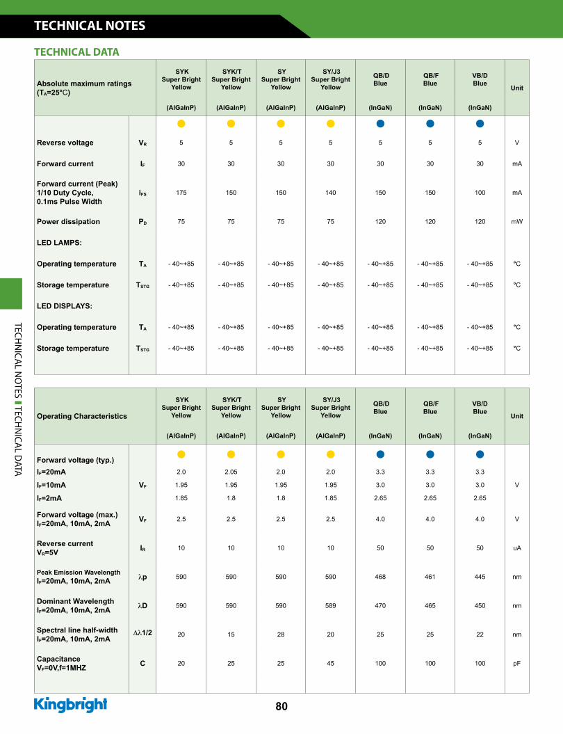
Absolute maximum ratings (TA=25°C)
SYKSuper Bright
Yellow
SYK/TSuper Bright
Yellow
SYSuper Bright
Yellow
SY/J3Super Bright
Yellow
QB/DBlue
QB/FBlue
VB/DBlue
Unit
(AlGaInP) (AlGaInP) (AlGaInP) (AlGaInP) (InGaN) (InGaN) (InGaN)
Reverse voltage VR 5 5 5 5 5 5 5 V
Forward current IF 30 30 30 30 30 30 30 mA
Forward current (Peak) 1/10 Duty Cycle,0.1ms Pulse Width
iFS 175 150 150 140 150 150 100 mA
Power dissipation PD 75 75 75 75 120 120 120 mW
LED LAMPS:
Operating temperature TA - 40~+85 - 40~+85 - 40~+85 - 40~+85 - 40~+85 - 40~+85 - 40~+85 °C
Storage temperature TSTG - 40~+85 - 40~+85 - 40~+85 - 40~+85 - 40~+85 - 40~+85 - 40~+85 °C
LED DISPLAYS:
Operating temperature TA - 40~+85 - 40~+85 - 40~+85 - 40~+85 - 40~+85 - 40~+85 - 40~+85 °C
Storage temperature TSTG - 40~+85 - 40~+85 - 40~+85 - 40~+85 - 40~+85 - 40~+85 - 40~+85 °C
Operating Characteristics
SYKSuper Bright
Yellow
SYK/TSuper Bright
Yellow
SYSuper Bright
Yellow
SY/J3Super Bright
Yellow
QB/DBlue
QB/FBlue
VB/DBlue
Unit
(AlGaInP) (AlGaInP) (AlGaInP) (AlGaInP) (InGaN) (InGaN) (InGaN)
Forward voltage (typ.)IF=20mA
VF
2.0 2.05 2.0 2.0 3.3 3.3 3.3
VIF=10mA 1.95 1.95 1.95 1.95 3.0 3.0 3.0
IF=2mA 1.85 1.8 1.8 1.85 2.65 2.65 2.65
Forward voltage (max.)IF=20mA, 10mA, 2mA VF 2.5 2.5 2.5 2.5 4.0 4.0 4.0 V
Reverse currentVR=5V IR 10 10 10 10 50 50 50 uA
Peak Emission WavelengthIF=20mA, 10mA, 2mA lp 590 590 590 590 468 461 445 nm
Dominant Wavelength IF=20mA, 10mA, 2mA lD 590 590 590 589 470 465 450 nm
Spectral line half-widthIF=20mA, 10mA, 2mA
Dl1/2 20 15 28 20 25 25 22 nm
CapacitanceVF=0V,f=1MHZ C 20 25 25 45 100 100 100 pF
TECHNICAL DATA
TECHN
ICAL N
OTES TECH
NICA
L DATA
www.KingbrightUSA.com
TECHNICAL NOTES
81
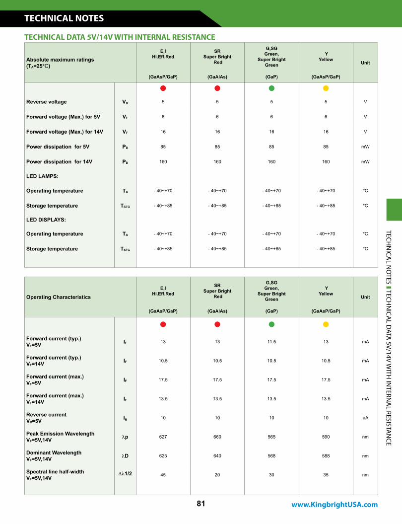
Absolute maximum ratings (TA=25°C)
E,I Hi.Eff.Red
SRSuper Bright
Red
G,SGGreen,
Super Bright Green
YYellow
Unit
(GaAsP/GaP) (GaAlAs) (GaP) (GaAsP/GaP)
Reverse voltage VR 5 5 5 5 V
Forward voltage (Max.) for 5V VF 6 6 6 6 V
Forward voltage (Max.) for 14V VF 16 16 16 16 V
Power dissipation for 5V PD 85 85 85 85 mW
Power dissipation for 14V PD 160 160 160 160 mW
LED LAMPS:
Operating temperature TA - 40~+70 - 40~+70 - 40~+70 - 40~+70 °C
Storage temperature TSTG - 40~+85 - 40~+85 - 40~+85 - 40~+85 °C
LED DISPLAYS:
Operating temperature TA - 40~+70 - 40~+70 - 40~+70 - 40~+70 °C
Storage temperature TSTG - 40~+85 - 40~+85 - 40~+85 - 40~+85 °C
Operating CharacteristicsE,I
Hi.Eff.Red
SRSuper Bright
Red
G,SGGreen,
Super Bright Green
YYellow
Unit
(GaAsP/GaP) (GaAlAs) (GaP) (GaAsP/GaP)
Forward current (typ.)VF=5V IF 13 13 11.5 13 mA
Forward current (typ.)VF=14V IF 10.5 10.5 10.5 10.5 mA
Forward current (max.)VF=5V IF 17.5 17.5 17.5 17.5 mA
Forward current (max.)VF=14V IF 13.5 13.5 13.5 13.5 mA
Reverse currentVR=5V IR 10 10 10 10 uA
Peak Emission WavelengthVF=5V,14V lp 627 660 565 590 nm
Dominant WavelengthVF=5V,14V lD 625 640 568 588 nm
Spectral line half-widthVF=5V,14V
Dl1/2 45 20 30 35 nm
TECHNICAL DATA 5V/14V WITH INTERNAL RESISTANCE
TECHN
ICAL N
OTES TECH
NICA
L DATA
5V/14V WITH
INTERN
AL RESISTA
NCE
TECHNICAL NOTES
82
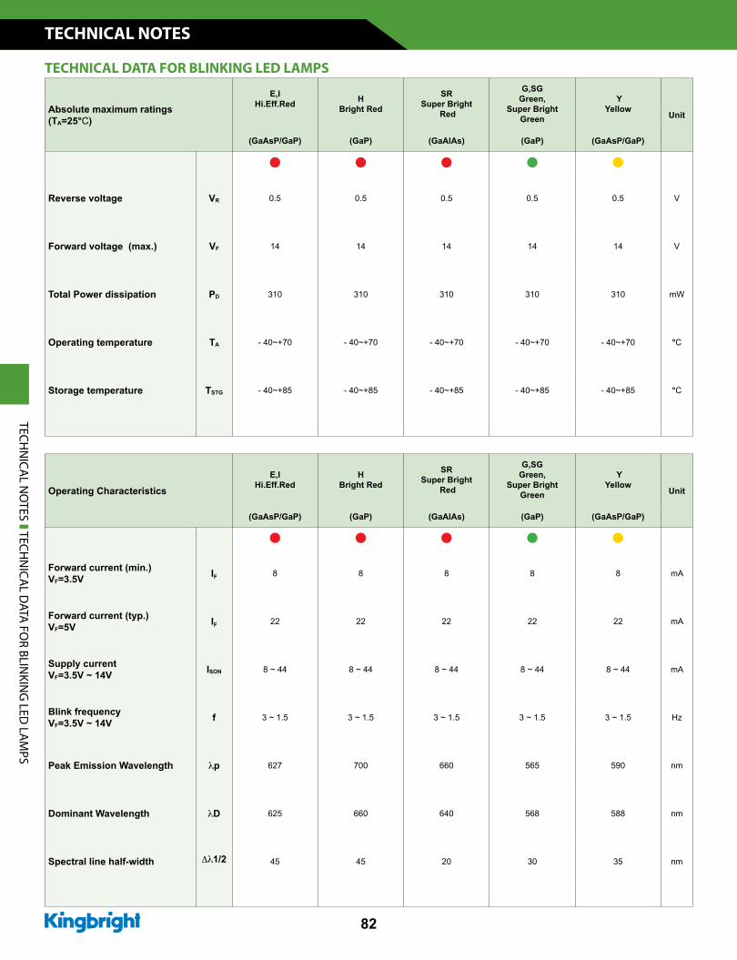
Absolute maximum ratings (TA=25°C)
E,IHi.Eff.Red H
Bright Red
SRSuper Bright
Red
G,SGGreen,
Super Bright Green
YYellow
Unit
(GaAsP/GaP) (GaP) (GaAlAs) (GaP) (GaAsP/GaP)
Reverse voltage VR 0.5 0.5 0.5 0.5 0.5 V
Forward voltage (max.) VF 14 14 14 14 14 V
Total Power dissipation PD 310 310 310 310 310 mW
Operating temperature TA - 40~+70 - 40~+70 - 40~+70 - 40~+70 - 40~+70 °C
Storage temperature TSTG - 40~+85 - 40~+85 - 40~+85 - 40~+85 - 40~+85 °C
Operating CharacteristicsE,I
Hi.Eff.RedH
Bright Red
SRSuper Bright
Red
G,SGGreen,
Super Bright Green
YYellow
Unit
(GaAsP/GaP) (GaP) (GaAlAs) (GaP) (GaAsP/GaP)
Forward current (min.)VF=3.5V IF 8 8 8 8 8 mA
Forward current (typ.)VF=5V IF 22 22 22 22 22 mA
Supply currentVF=3.5V ~ 14V ISON 8 ~ 44 8 ~ 44 8 ~ 44 8 ~ 44 8 ~ 44 mA
Blink frequencyVF=3.5V ~ 14V f 3 ~ 1.5 3 ~ 1.5 3 ~ 1.5 3 ~ 1.5 3 ~ 1.5 Hz
Peak Emission Wavelength lp 627 700 660 565 590 nm
Dominant Wavelength lD 625 660 640 568 588 nm
Spectral line half-width Dl1/2 45 45 20 30 35 nm
TECHNICAL DATA FOR BLINKING LED LAMPS
TECHN
ICAL N
OTES TECH
NICA
L DATA
FOR BLIN
KING
LED LA
MPS
www.KingbrightUSA.com
TECHNICAL NOTES
83
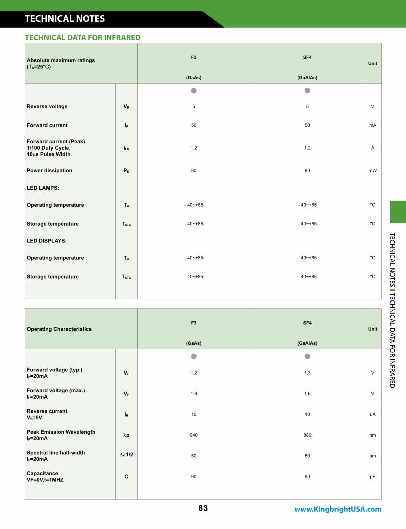
Absolute maximum ratings (TA=25°C)
F3 SF4Unit
(GaAs) (GaAlAs)
Reverse voltage VR 5 5 V
Forward current IF 50 50 mA
Forward current (Peak) 1/100 Duty Cycle,10ms Pulse Width
iFS 1.2 1.2 A
Power dissipation PD 80 80 mW
LED LAMPS:
Operating temperature TA - 40~+85 - 40~+85 °C
Storage temperature TSTG - 40~+85 - 40~+85 °C
LED DISPLAYS:
Operating temperature TA - 40~+85 - 40~+85 °C
Storage temperature TSTG - 40~+85 - 40~+85 °C
Operating CharacteristicsF3 SF4
Unit
(GaAs) (GaAlAs)
Forward voltage (typ.)IF=20mA VF 1.2 1.3 V
Forward voltage (max.)IF=20mA VF 1.6 1.6 V
Reverse currentVR=5V IR 10 10 uA
Peak Emission WavelengthIF=20mA lp 940 880 nm
Spectral line half-widthIF=20mA
Dl1/2 50 50 nm
CapacitanceVF=0V,f=1MHZ C 90 90 pF
TECHNICAL DATA FOR INFRARED
TECHN
ICAL N
OTES TECH
NICA
L DATA
FOR IN
FRARED
TECHNICAL NOTES
84
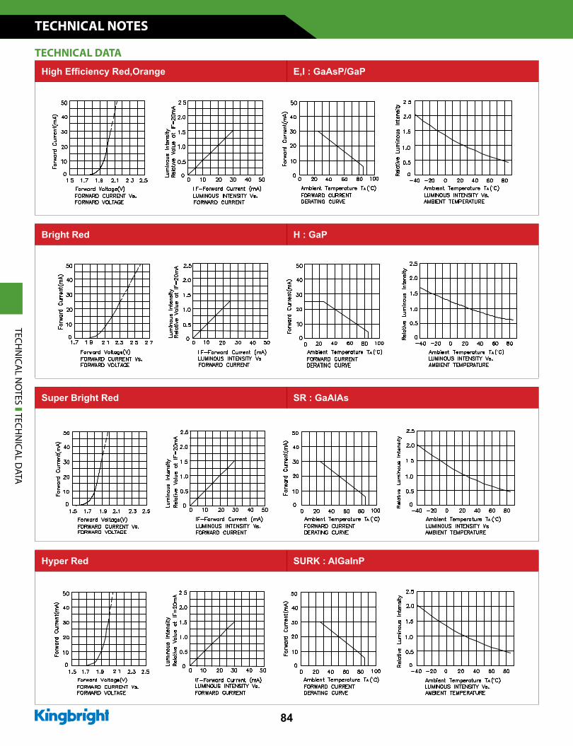
High Efficiency Red,Orange E,I : GaAsP/GaP
Super Bright Red SR : GaAlAs
Bright Red H : GaP
Hyper Red SURK : AlGaInPTECH
NICA
L NO
TES TECHN
ICAL D
ATA
TECHNICAL DATA
www.KingbrightUSA.com
TECHNICAL NOTES
85
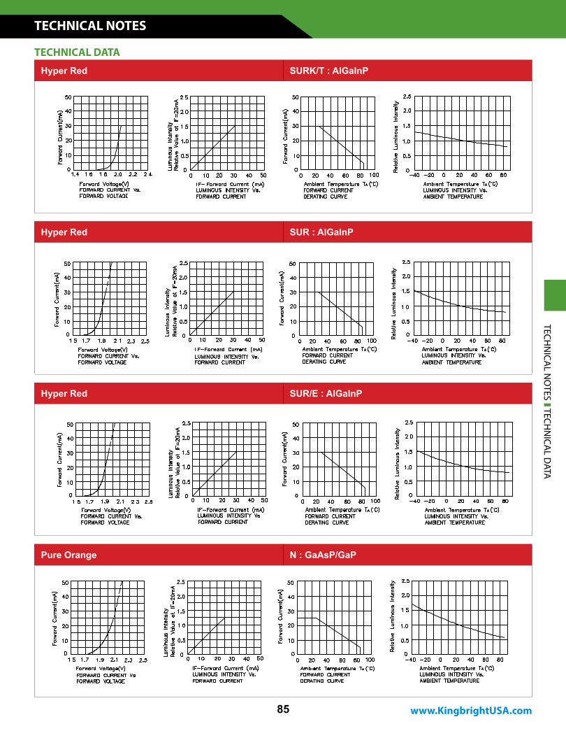
Hyper Red SUR : AlGaInP
Hyper Red SURK/T : AlGaInP
Hyper Red SUR/E : AlGaInP
Pure Orange N : GaAsP/GaP
TECHNICAL DATA
TECHN
ICAL N
OTES TECH
NICA
L DATA
TECHNICAL NOTES
86
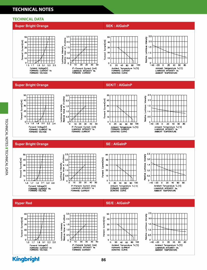
Super Bright Orange SE : AlGaInP
Hyper Red SE/E : AlGaInP
Super Bright Orange SEK : AlGaInP
Super Bright Orange SEK/T : AlGaInP
TECHNICAL DATA
TECHN
ICAL N
OTES TECH
NICA
L DATA
www.KingbrightUSA.com
TECHNICAL NOTES
87
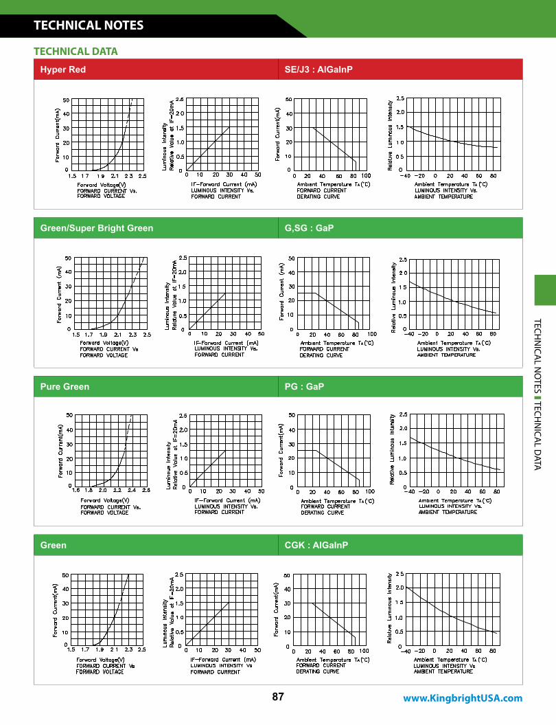
Hyper Red SE/J3 : AlGaInP
Green/Super Bright Green G,SG : GaP
Pure Green PG : GaP
Green CGK : AlGaInP
TECHNICAL DATA
TECHN
ICAL N
OTES TECH
NICA
L DATA
TECHNICAL NOTES
88
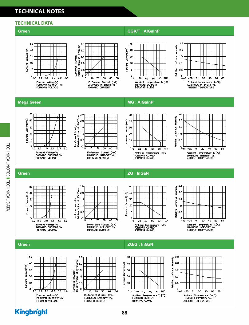
Green ZG/G : InGaN
Mega Green MG : AlGaInP
Green CGK/T : AlGaInP
Green ZG : InGaN
TECHNICAL DATA
TECHN
ICAL N
OTES TECH
NICA
L DATA
www.KingbrightUSA.com
TECHNICAL NOTES
89
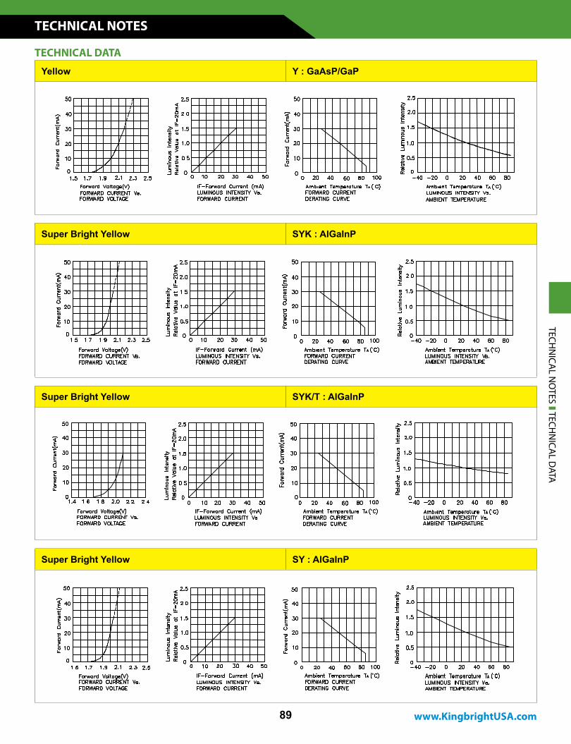
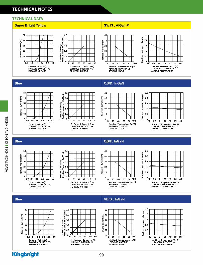
Super Bright Yellow SYK : AlGaInP
Yellow Y : GaAsP/GaP
Super Bright Yellow SYK/T : AlGaInP
Super Bright Yellow SY : AlGaInP
TECHNICAL DATA
TECHN
ICAL N
OTES TECH
NICA
L DATA
TECHNICAL NOTES
90
Blue VB/D : InGaN
Blue QB/F: InGaN
Super Bright Yellow SY/J3 : AlGaInP
Blue QB/D: InGaN
TECHNICAL DATA
TECHN
ICAL N
OTES TECH
NICA
L DATA
www.KingbrightUSA.com
TECHNICAL NOTES
91
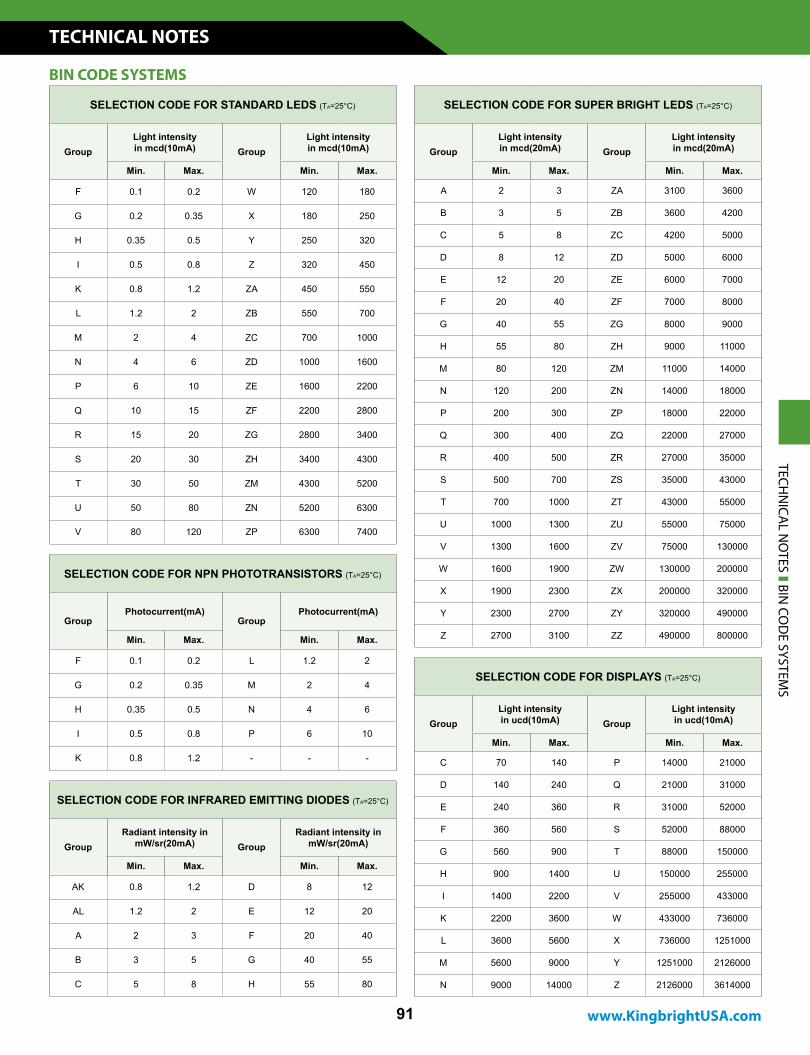
SELECTION CODE FOR STANDARD LEDS (TA=25°C)
GroupLight intensity in mcd(10mA) Group
Light intensity in mcd(10mA)
Min. Max. Min. Max.
F 0.1 0.2 W 120 180
G 0.2 0.35 X 180 250
H 0.35 0.5 Y 250 320
I 0.5 0.8 Z 320 450
K 0.8 1.2 ZA 450 550
L 1.2 2 ZB 550 700
M 2 4 ZC 700 1000
N 4 6 ZD 1000 1600
P 6 10 ZE 1600 2200
Q 10 15 ZF 2200 2800
R 15 20 ZG 2800 3400
S 20 30 ZH 3400 4300
T 30 50 ZM 4300 5200
U 50 80 ZN 5200 6300
V 80 120 ZP 6300 7400
SELECTION CODE FOR SUPER BRIGHT LEDS (TA=25°C)
GroupLight intensity in mcd(20mA) Group
Light intensity in mcd(20mA)
Min. Max. Min. Max.
A 2 3 ZA 3100 3600
B 3 5 ZB 3600 4200
C 5 8 ZC 4200 5000
D 8 12 ZD 5000 6000
E 12 20 ZE 6000 7000
F 20 40 ZF 7000 8000
G 40 55 ZG 8000 9000
H 55 80 ZH 9000 11000
M 80 120 ZM 11000 14000
N 120 200 ZN 14000 18000
P 200 300 ZP 18000 22000
Q 300 400 ZQ 22000 27000
R 400 500 ZR 27000 35000
S 500 700 ZS 35000 43000
T 700 1000 ZT 43000 55000
U 1000 1300 ZU 55000 75000
V 1300 1600 ZV 75000 130000
W 1600 1900 ZW 130000 200000
X 1900 2300 ZX 200000 320000
Y 2300 2700 ZY 320000 490000
Z 2700 3100 ZZ 490000 800000
SELECTION CODE FOR DISPLAYS (TA=25°C)
GroupLight intensity in ucd(10mA) Group
Light intensity in ucd(10mA)
Min. Max. Min. Max.
C 70 140 P 14000 21000
D 140 240 Q 21000 31000
E 240 360 R 31000 52000
F 360 560 S 52000 88000
G 560 900 T 88000 150000
H 900 1400 U 150000 255000
I 1400 2200 V 255000 433000
K 2200 3600 W 433000 736000
L 3600 5600 X 736000 1251000
M 5600 9000 Y 1251000 2126000
N 9000 14000 Z 2126000 3614000
SELECTION CODE FOR NPN PHOTOTRANSISTORS (TA=25°C)
GroupPhotocurrent(mA)
GroupPhotocurrent(mA)
Min. Max. Min. Max.
F 0.1 0.2 L 1.2 2
G 0.2 0.35 M 2 4
H 0.35 0.5 N 4 6
I 0.5 0.8 P 6 10
K 0.8 1.2 - - -
SELECTION CODE FOR INFRARED EMITTING DIODES (TA=25°C)
GroupRadiant intensity in
mW/sr(20mA) GroupRadiant intensity in
mW/sr(20mA)
Min. Max. Min. Max.
AK 0.8 1.2 D 8 12
AL 1.2 2 E 12 20
A 2 3 F 20 40
B 3 5 G 40 55
C 5 8 H 55 80
BIN CODE SYSTEMS
TECHN
ICAL N
OTES BIN
COD
E SYSTEMS
TECHNICAL NOTES
92
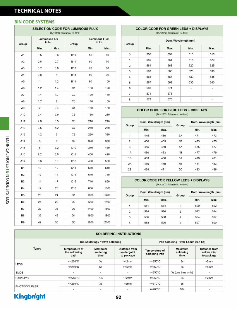
SELECTION CODE FOR LUMINOUS FLUX (TA=25°C;Tolerance: +/-15%)
Group
Luminous Flux in lm Group
Luminous Flux in lm
Min. Max. Min. Max.
A1 0.5 0.6 B10 50 60
A2 0.6 0.7 B11 60 70
A3 0.7 0.8 B12 70 80
A4 0.8 1 B13 80 90
A5 1 1.2 B14 90 100
A6 1.2 1.4 C1 100 120
A7 1.4 1.7 C2 120 140
A8 1.7 2 C3 140 160
A9 2 2.4 C4 160 180
A10 2.4 2.9 C5 180 210
A11 2.9 3.5 C6 210 240
A12 3.5 4.2 C7 240 280
A13 4.2 5 C8 280 320
A14 5 6 C9 320 370
A15 6 7.2 C10 370 430
A16 7.2 8.6 C11 430 490
A17 8.6 10 C12 490 560
B1 10 12 C13 560 640
B2 12 14 C14 640 740
B3 14 17 C15 740 850
B4 17 20 C16 850 1000
B5 20 24 D1 1000 1200
B6 24 29 D2 1200 1400
B7 29 35 D3 1400 1600
B8 35 42 D4 1600 1800
B9 42 50 D5 1800 2100
COLOR CODE FOR GREEN LEDS + DISPLAYS(TA =25°C; Tolerance: +/-1nm)
GroupDom. Wavelength (nm)
Min. Max. Min. Max.
0 556 559 510 515
1 559 561 515 520
2 561 563 520 525
3 563 565 525 530
4 565 567 530 535
5 567 569 535 540
6 569 571 - -
7 571 573 - -
8 573 575 - -
COLOR CODE FOR BLUE LEDS + DISPLAYS (TA =25°C; Tolerance: +/-1nm)
GroupDom. Wavelength (nm)
GroupDom. Wavelength (nm)
Min. Max. Min. Max.
1 445 450 3A 471 473
2 450 455 3B 473 475
3 455 460 4A 475 477
1A 460 463 4B 477 479
1B 463 466 5A 479 481
2A 466 469 5B 481 483
2B 469 471 5C 483 486
SOLDERING INSTRUCTIONS
Types
Dip soldering / * wave soldering Iron soldering (with 1.5mm iron tip)
Temperature of the soldering
bath
Maximumsoldering
time
Distance fromsolder jointto package
Temperature ofsoldering iron
Maximumsoldering
time
Distance fromsolder jointto package
LEDS<=260°C 3s >=2mm <=350°C 3s >2mm
<=260°C 5s >=5mm <=350°C 5s >5mm
SMDS - - - <=350°C 3s (one time only) -
DISPLAYS *<=260°C *3s *>2mm <=350°C 3s >2mm
PHOTOCOUPLER<=260°C 3s >2mm <=310°C 3s -
- - - <=260°C 10s -
BIN CODE SYSTEMS
TECHN
ICAL N
OTES BIN
COD
E SYSTEMS
COLOR CODE FOR YELLOW LEDS + DISPLAYS (TA =25°C; Tolerance: +/-1nm)
GroupDom. Wavelength (nm)
GroupDom. Wavelength (nm)
Min. Max. Min. Max.
1 581 584 5 590 592
2 584 586 6 592 594
3 586 588 7 594 597
4 588 590 8 597 600
www.KingbrightUSA.com
TECHNICAL NOTES
93
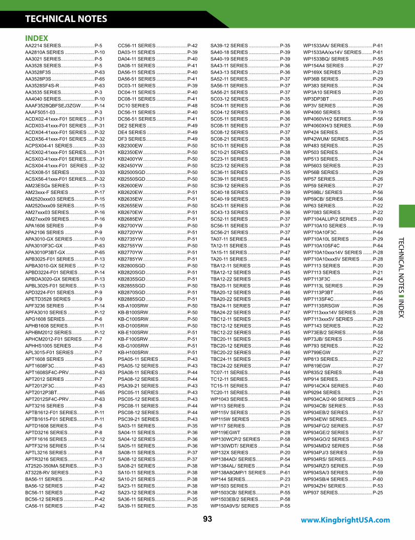
AA2214 SERIES.........................P-5AA2810A SERIES ......................P-10AA3021 SERIES.........................P-5AA3528 SERIES.........................P-5AA3528F3S ................................P-63AA3528P3S ................................P-65AA3528SF4S-R ..........................P-63AA3535 SERIES.........................P-3AA4040 SERIES.........................P-10AAAF3528QBFSEJ3ZGW ..........P-14AAAF5051-03 .............................P-3ACDX02-41xxx-F01 SERIES .....P-31ACDX03-41xxx-F01 SERIES .....P-31ACDX04-41xxx-F01 SERIES .....P-32ACDX56-41xxx-F01 SERIES .....P-32ACPSX04-41 SERIES ................P-33ACSX02-41xxx-F01 SERIES......P-31ACSX03-41xxx-F01 SERIES......P-31ACSX04-41xxx-F01 SERIES ....P-32ACSX08-51 SERIES ..................P-33ACSX56-41xxx-F01 SERIES......P-32AM23ESGx SERIES...................P-13AM23xxx-F SERIES ...................P-17AM2520xxx03 SERIES...............P-15AM2520xxx09 SERIES...............P-15AM27xxx03 SERIES...................P-16AM27xxx09 SERIES...................P-16APA1606 SERIES ......................P-9APA2106 SERIES ......................P-9APA3010-GX SERIES ................P-10APA3010F3C-GX .......................P-63APA3010P3BT-GX .....................P-65APB3025-F01 SERIES ...............P-13APBA3010-GX SERIES .............P-12APBD3224-F01 SERIES ............P-14APBDA3020-GX SERIES ...........P-13APBL3025-F01 SERIES .............P-13APD3224-F01 SERIES...............P-9APETD3528 SERIES .................P-9APF3236 SERIES ......................P-14APFA3010 SERIES ....................P-12APG1608 SERIES ......................P-6APHB1608 SERIES....................P-11APHBM2012 SERIES.................P-12APHCM2012-F01 SERIES .........P-7APHHS1005 SERIES .................P-6APL3015-F01 SERIES ...............P-7APT1608 SERIES ......................P-6APT1608F3C ..............................P-63APT1608SF4C-PRV ...................P-63APT2012 SERIES ......................P-7APT2012F3C ..............................P-63APT2012P3BT ............................P-65APT2012SF4C-PRV ...................P-63APT3216 SERIES ......................P-8APTB1612-F01 SERIES.............P-11APTB1615-F01 SERIES.............P-11APTD1608 SERIES ....................P-6APTD3216 SERIES ....................P-8APTF1616 SERIES ....................P-12APTF3216 SERIES ....................P-14APTL3216 SERIES ....................P-8APTR3216 SERIES ....................P-17AT2520-350MA SERIES .............P-3AT3228-RV SERIES ...................P-3BA56-11 SERIES ........................P-42BA56-12 SERIES .......................P-42BC56-11 SERIES .......................P-42BC56-12 SERIES .......................P-42CA56-11 SERIES .......................P-42
CC56-11 SERIES .......................P-42DA03-11 SERIES .......................P-39DA04-11 SERIES .......................P-40DA08-11 SERIES .......................P-41DA56-11 SERIES .......................P-40DA56-51 SERIES .......................P-41DC03-11 SERIES .......................P-39DC04-11 SERIES .......................P-40DC08-11 SERIES .......................P-41DC10 SERIES ............................P-48DC56-11 SERIES .......................P-40DC56-51 SERIES .......................P-41DE2 SERIES ..............................P-49DE4 SERIES ..............................P-49DF3 SERIES...............................P-49KB2300EW .................................P-50KB2350EW .................................P-50KB2400YW .................................P-50KB2450YW .................................P-50KB2500SGD ...............................P-50KB2550SGD ...............................P-50KB2600EW .................................P-50KB2620EW .................................P-51KB2635EW .................................P-51KB2655EW .................................P-50KB2670EW .................................P-51KB2685EW .................................P-51KB2700YW .................................P-50KB2720YW .................................P-51KB2735YW .................................P-51KB2755YW .................................P-50KB2770YW .................................P-51KB2785YW .................................P-51KB2800SGD ...............................P-50KB2820SGD ...............................P-51KB2835SGD ...............................P-51KB2855SGD ...............................P-50KB2870SGD ...............................P-51KB2885SGD ...............................P-51KB-A100SRW .............................P-50KB-B100SRW .............................P-50KB-C100SRW .............................P-50KB-D100SRW .............................P-50KB-E100SRW .............................P-51KB-F100SRW .............................P-51KB-G100SRW ............................P-51KB-H100SRW .............................P-51PSA05-11 SERIES .....................P-43PSA05-12 SERIES .....................P-43PSA08-11 SERIES .....................P-44PSA08-12 SERIES .....................P-44PSA39-21 SERIES .....................P-43PSC05-11 SERIES .....................P-43PSC05-12 SERIES .....................P-43PSC08-11 SERIES .....................P-44PSC08-12 SERIES .....................P-44PSC39-21 SERIES .....................P-43SA03-11 SERIES ........................P-35SA04-11 SERIES ........................P-36SA04-12 SERIES .......................P-36SA05-11 SERIES ........................P-36SA08-11 SERIES ........................P-37SA08-12 SERIES .......................P-37SA08-21 SERIES .......................P-38SA10-11 SERIES ........................P-38SA10-21 SERIES .......................P-38SA23-11 SERIES ........................P-38SA23-12 SERIES .......................P-38SA36-11 SERIES ........................P-35SA39-11 SERIES ........................P-35
SA39-12 SERIES .......................P-35SA40-18 SERIES .......................P-39SA40-19 SERIES .......................P-39SA43-11 SERIES ........................P-36SA43-13 SERIES .......................P-36SA52-11 SERIES ........................P-37SA56-11 SERIES ........................P-37SA56-21 SERIES .......................P-37SC03-12 SERIES .......................P-35SC04-11 SERIES .......................P-36SC04-12 SERIES .......................P-36SC05-11 SERIES .......................P-36SC08-11 SERIES .......................P-37SC08-12 SERIES .......................P-37SC08-21 SERIES .......................P-38SC10-11 SERIES .......................P-38SC10-21 SERIES .......................P-38SC23-11 SERIES .......................P-38SC23-12 SERIES .......................P-38SC36-11 SERIES .......................P-35SC39-11 SERIES .......................P-35SC39-12 SERIES .......................P-35SC40-18 SERIES .......................P-39SC40-19 SERIES .......................P-39SC43-11 SERIES .......................P-36SC43-13 SERIES .......................P-36SC52-11 SERIES .......................P-37SC56-11 SERIES .......................P-37SC56-21 SERIES .......................P-37TA07-11 SERIES ........................P-44TA12-11 SERIES ........................P-45TA15-11 SERIES ........................P-47TA20-11 SERIES ........................P-46TBA12-11 SERIES .....................P-45TBA12-12 SERIES .....................P-45TBA12-22 SERIES .....................P-45TBA20-11 SERIES .....................P-46TBA20-12 SERIES .....................P-46TBA20-22 SERIES .....................P-46TBA24-11 SERIES .....................P-47TBA24-22 SERIES .....................P-47TBC12-11 SERIES .....................P-45TBC12-12 SERIES .....................P-45TBC12-22 SERIES .....................P-45TBC20-11 SERIES .....................P-46TBC20-12 SERIES .....................P-46TBC20-22 SERIES .....................P-46TBC24-11 SERIES .....................P-47TBC24-22 SERIES .....................P-47TC07-11 SERIES ........................P-44TC12-11 SERIES ........................P-45TC15-11 SERIES ........................P-47TC20-11 SERIES ........................P-46WP1043 SERIES........................P-48WP113 SERIES ..........................P-24WP115V SERIES .......................P-25WP115W SERIES ......................P-26WP117 SERIES ..........................P-28WP119EGWT .............................P-28WP130WCP/2 SERIES ..............P-58WP130WDT/ SERIES ................P-54WP132X SERIES .......................P-20WP1384AD/ SERIES..................P-54WP1384AL/ SERIES ..................P-54WP138A8QMP/1 SERIES ..........P-61WP144 SERIES..........................P-23WP1503 SERIES........................P-21WP1503CB/ SERIES..................P-55WP1503EB/2 SERIES ................P-58WP150A9VS/ SERIES ...............P-55
WP1533AA/ SERIES ..................P-61WP1533AA/xx14V SERIES ........P-61WP1533BQ/ SERIES .................P-55WP154A4 SERIES .....................P-27WP169X SERIES .......................P-23WP36B SERIES .........................P-29WP383 SERIES..........................P-24WP3A10 SERIES .......................P-20WP3DP3BT ................................P-65WP3V SERIES ...........................P-26WP4060 SERIES........................P-19WP4060VH/2 SERIES................P-56WP4060XH/3 SERIES................P-59WP424 SERIES..........................P-25WP42WUM/ SERIES ..................P-54WP483 SERIES..........................P-25WP503 SERIES..........................P-24WP513 SERIES..........................P-24WP5603 SERIES........................P-23WP56B SERIES .........................P-29WP57 SERIES............................P-26WP59 SERIES............................P-27WP59BL/ SERIES ......................P-56WP59CB/ SERIES......................P-56WP63 SERIES............................P-22WP7083 SERIES........................P-22WP7104ALUP/2 SERIES ...........P-60WP710A10 SERIES ...................P-19WP710A10F3C...........................P-64WP710A10L SERIES .................P-29WP710A10SF4C ........................P-64WP710A10xxx14V SERIES .......P-28WP710A10xxx5V SERIES .........P-28WP7113 SERIES ........................P-20WP7113 SERIES ........................P-21WP7113F3C ...............................P-64WP7113L SERIES ......................P-29WP7113P3BT .............................P-65WP7113SF4C .............................P-64WP7113SRSGW ........................P-26WP7113xxx14V SERIES ............P-28WP7113xxx5V SERIES ..............P-28WP7143 SERIES........................P-22WP73EB/2 SERIES ....................P-58WP73JB/ SERIES ......................P-55WP793 SERIES..........................P-22WP799EGW ...............................P-27WP813 SERIES..........................P-22WP819EGW ...............................P-27WP835/2 SERIES.......................P-48WP914 SERIES..........................P-23WP914CK/4 SERIES..................P-60WP9294 SERIES........................P-21WP934CA/2-90 SERIES ............P-56WP934CB/ SERIES....................P-53WP934EB/2 SERIES ..................P-57WP934EW/ SERIES ...................P-53WP934FG/2 SERIES..................P-57WP934GE/2 SERIES .................P-57WP934GO/2 SERIES .................P-57WP934MD/2 SERIES .................P-58WP934PJ/3 SERIES ..................P-59WP934RS/ SERIES....................P-53WP934RZ/3 SERIES ..................P-59WP934SA/3 SERIES ..................P-59WP934SB/4 SERIES ..................P-60WP934ZH/ SERIES ....................P-53WP937 SERIES..........................P-25
TECHN
ICAL N
OTES IN
DEX
INDEX
TECHNICAL NOTES
94
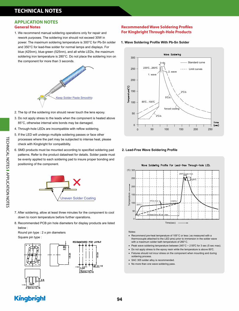
1. We recommend manual soldering operations only for repair and rework purposes. The soldering iron should not exceed 30W in power. The maximum soldering temperature is 300°C for Pb-Sn solder and 350°C for lead-free solder for normal lamps and displays. For blue (425nm), blue-green (525nm), and all white LEDs, the maximum soldering iron temperature is 280°C. Do not place the soldering iron on the component for more than 3 seconds.
2. The tip of the soldering iron should never touch the lens epoxy.
3. Do not apply stress to the leads when the component is heated above 85°C, otherwise internal wire bonds may be damaged.
5. If the LED will undergo multiple soldering passes or face other processes where the part may be subjected to intense heat, please check with Kingbright for compatibility.
patterns. Refer to the product datasheet for details. Solder paste must be evenly applied to each soldering pad to insure proper bonding and positioning of the component.
7. After soldering, allow at least three minutes for the component to cool down to room temperature before further operations.
8. Recommended PCB pin hole diameters for display products are listed below : Round pin type : 2 x pin diameters Square pin type :
For Kingbright Through-Hole ProductsGeneral NotesAPPLICATION NOTES
TECHN
ICAL N
OTES A
PPLICATION
NO
TESNotes: • Recommend pre-heat temperature of 105° C or less ( as measured with a thermocouple attached to the LED pins) prior to immersion in the solder wave with a maximum solder bath temperature of 260° C. • Peak wave soldering temperature between 245° C ~ 2 55°C for 3 sec (5 sec max). • Do not apply stress to the epoxy resin while the temperature is above 85°C. • Fixtures should not incur stress on the component when mounting and during soldering process. • SAC 305 solder alloy is recommended. • No more than one wave soldering pass.
Preheat time: 60 sec max.
<30°C.
4°C/s max
Time(sec)
0
50
100
150
200
250
300
(85°C)Tem
pera
ture
255°C/5 sec max.
(100°C)
(°C)
2. waveLimit curves
Standard curve3~6s
235°C...260°C
1. wave
300
250
200
2°C/s
250200150
2°C/s
150
100
50
85°C...100°C
500
0
forced cooling
100
5°C/s
www.KingbrightUSA.com
TECHNICAL NOTES
95
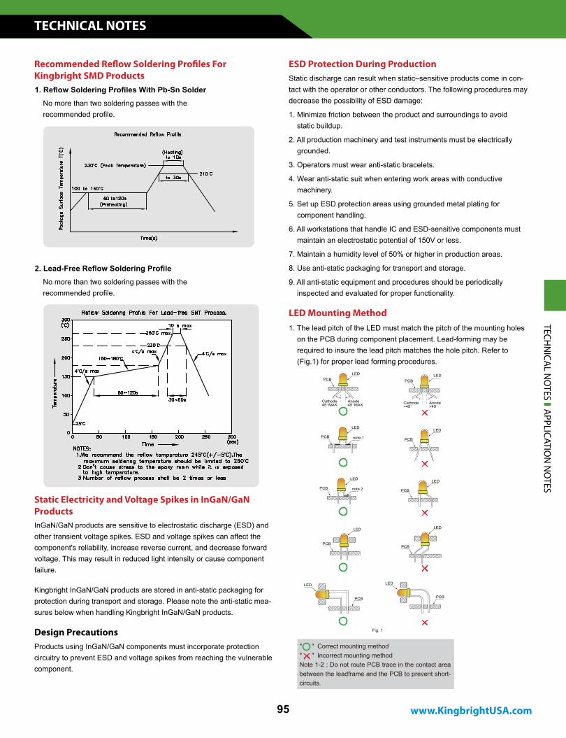
1. Reflow Soldering Profiles With Pb-Sn Solder
Recommended Reflow Soldering Profiles For Kingbright SMD Products
No more than two soldering passes with the recommended profile.
2. Lead-Free Reflow Soldering Profile No more than two soldering passes with the recommended profile.
InGaN/GaN products are sensitive to electrostatic discharge (ESD) and other transient voltage spikes. ESD and voltage spikes can affect the component's reliability, increase reverse current, and decrease forward voltage. This may result in reduced light intensity or cause component failure.
Kingbright InGaN/GaN products are stored in anti-static packaging for protection during transport and storage. Please note the anti-static mea-sures below when handling Kingbright InGaN/GaN products.
Static Electricity and Voltage Spikes in InGaN/GaN Products
Design PrecautionsProducts using InGaN/GaN components must incorporate protection circuitry to prevent ESD and voltage spikes from reaching the vulnerable component.
ESD Protection During ProductionStatic discharge can result when static–sensitive products come in con-tact with the operator or other conductors. The following procedures may decrease the possibility of ESD damage:
1. Minimize friction between the product and surroundings to avoid static buildup.
2. All production machinery and test instruments must be electrically grounded.
3. Operators must wear anti-static bracelets.
4. Wear anti-static suit when entering work areas with conductive machinery.
5. Set up ESD protection areas using grounded metal plating for component handling.
6. All workstations that handle IC and ESD-sensitive components must maintain an electrostatic potential of 150V or less.
7. Maintain a humidity level of 50% or higher in production areas.
8. Use anti-static packaging for transport and storage.
9. All anti-static equipment and procedures should be periodically inspected and evaluated for proper functionality.
LED Mounting Method1. The lead pitch of the LED must match the pitch of the mounting holes on the PCB during component placement. Lead-forming may be required to insure the lead pitch matches the hole pitch. Refer to (Fig.1) for proper lead forming procedures.
TECHN
ICAL N
OTES A
PPLICATION
NO
TES
TECHNICAL NOTES
96
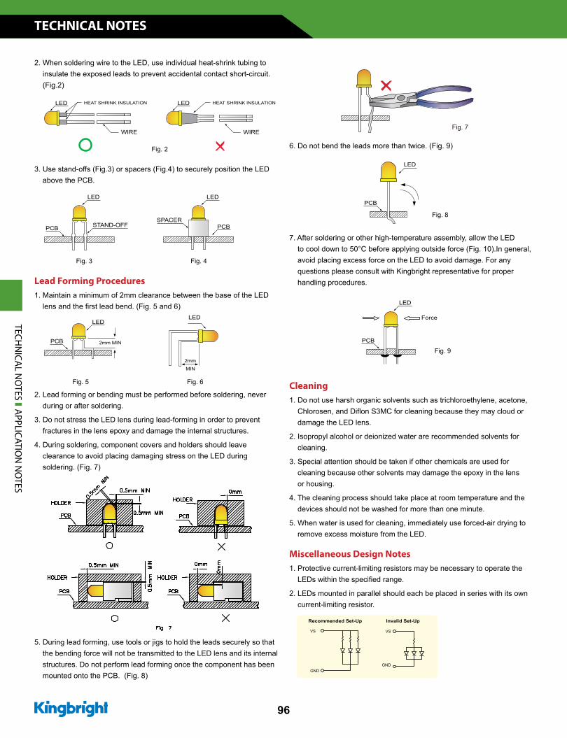
2. When soldering wire to the LED, use individual heat-shrink tubing to insulate the exposed leads to prevent accidental contact short-circuit. (Fig.2)
3. Use stand-offs (Fig.3) or spacers (Fig.4) to securely position the LED above the PCB.
Lead Forming Procedures1. Maintain a minimum of 2mm clearance between the base of the LED lens and the first lead bend. (Fig. 5 and 6)
2. Lead forming or bending must be performed before soldering, never during or after soldering.
3. Do not stress the LED lens during lead-forming in order to prevent fractures in the lens epoxy and damage the internal structures.
4. During soldering, component covers and holders should leave clearance to avoid placing damaging stress on the LED during soldering. (Fig. 7)
5. During lead forming, use tools or jigs to hold the leads securely so that the bending force will not be transmitted to the LED lens and its internal structures. Do not perform lead forming once the component has been mounted onto the PCB. (Fig. 8)
6. Do not bend the leads more than twice. (Fig. 9)
7. After soldering or other high-temperature assembly, allow the LED to cool down to 50°C before applying outside force (Fig. 10).In general, avoid placing excess force on the LED to avoid damage. For any questions please consult with Kingbright representative for proper handling procedures.
Cleaning1. Do not use harsh organic solvents such as trichloroethylene, acetone, Chlorosen, and Diflon S3MC for cleaning because they may cloud or damage the LED lens.
2. Isopropyl alcohol or deionized water are recommended solvents for cleaning.
3. Special attention should be taken if other chemicals are used for cleaning because other solvents may damage the epoxy in the lens or housing.
4. The cleaning process should take place at room temperature and the devices should not be washed for more than one minute.
5. When water is used for cleaning, immediately use forced-air drying to remove excess moisture from the LED.
Miscellaneous Design Notes1. Protective current-limiting resistors may be necessary to operate the LEDs within the specified range.
2. LEDs mounted in parallel should each be placed in series with its own current-limiting resistor.
TECHN
ICAL N
OTES A
PPLICATION
NO
TES
www.KingbrightUSA.com
TECHNICAL NOTES
97
3. The driving circuit should be designed to avoid reverse voltages and transient voltage spikes when the circuit is powered up or shut down.
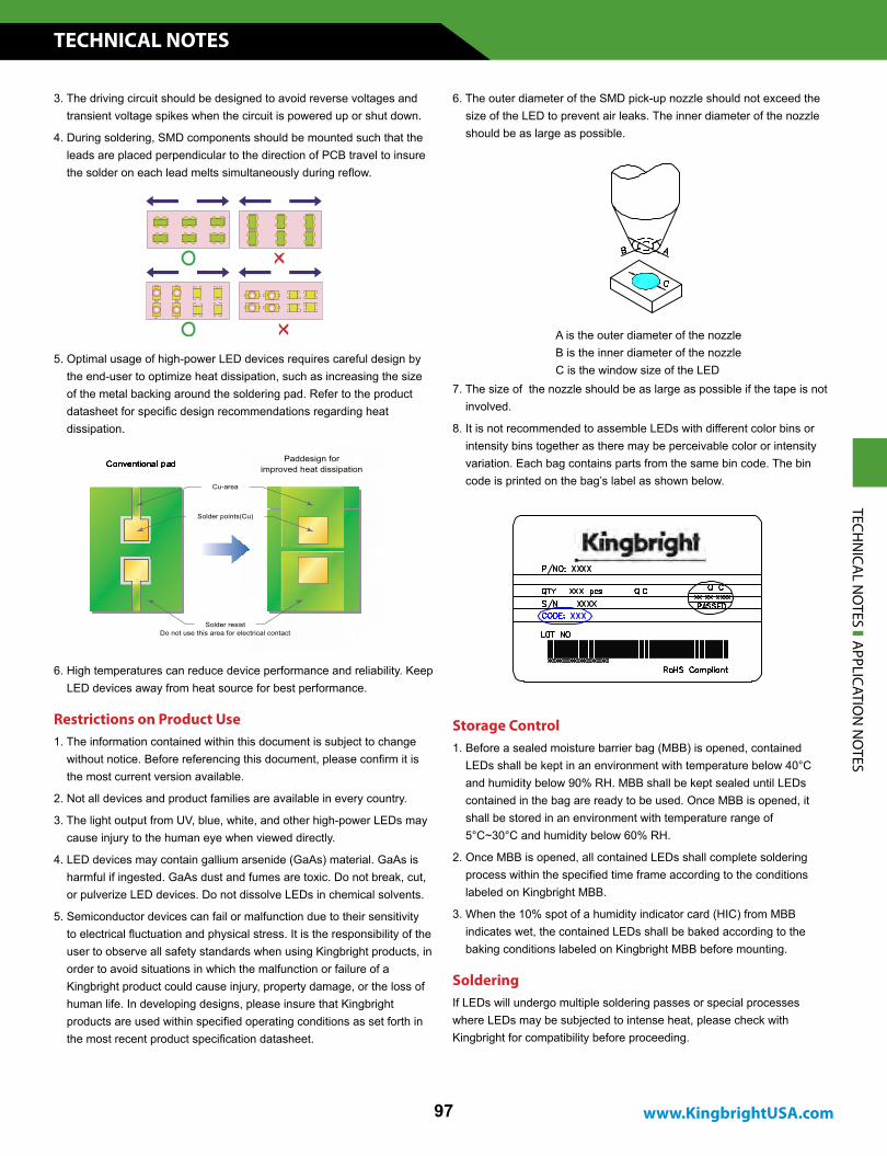
4. During soldering, SMD components should be mounted such that the leads are placed perpendicular to the direction of PCB travel to insure the solder on each lead melts simultaneously during reflow.
5. Optimal usage of high-power LED devices requires careful design by the end-user to optimize heat dissipation, such as increasing the size of the metal backing around the soldering pad. Refer to the product datasheet for specific design recommendations regarding heat dissipation.
6. High temperatures can reduce device performance and reliability. Keep LED devices away from heat source for best performance.
6. The outer diameter of the SMD pick-up nozzle should not exceed the size of the LED to prevent air leaks. The inner diameter of the nozzle should be as large as possible.
Restrictions on Product Use Storage Control1. Before a sealed moisture barrier bag (MBB) is opened, contained LEDs shall be kept in an environment with temperature below 40°C and humidity below 90% RH. MBB shall be kept sealed until LEDs contained in the bag are ready to be used. Once MBB is opened, it shall be stored in an environment with temperature range of 5°C~30°C and humidity below 60% RH.
2. Once MBB is opened, all contained LEDs shall complete soldering process within the specified time frame according to the conditions labeled on Kingbright MBB.
3. When the 10% spot of a humidity indicator card (HIC) from MBB indicates wet, the contained LEDs shall be baked according to the baking conditions labeled on Kingbright MBB before mounting.
SolderingIf LEDs will undergo multiple soldering passes or special processes where LEDs may be subjected to intense heat, please check with Kingbright for compatibility before proceeding.
A is the outer diameter of the nozzleB is the inner diameter of the nozzleC is the window size of the LED
7. The size of the nozzle should be as large as possible if the tape is not involved.
8. It is not recommended to assemble LEDs with different color bins or intensity bins together as there may be perceivable color or intensity variation. Each bag contains parts from the same bin code. The bin code is printed on the bag’s label as shown below.
1. The information contained within this document is subject to change without notice. Before referencing this document, please confirm it is the most current version available.
2. Not all devices and product families are available in every country.
3. The light output from UV, blue, white, and other high-power LEDs may cause injury to the human eye when viewed directly.
4. LED devices may contain gallium arsenide (GaAs) material. GaAs is harmful if ingested. GaAs dust and fumes are toxic. Do not break, cut, or pulverize LED devices. Do not dissolve LEDs in chemical solvents.
5. Semiconductor devices can fail or malfunction due to their sensitivity to electrical fluctuation and physical stress. It is the responsibility of the user to observe all safety standards when using Kingbright products, in order to avoid situations in which the malfunction or failure of a Kingbright product could cause injury, property damage, or the loss of human life. In developing designs, please insure that Kingbright products are used within specified operating conditions as set forth in the most recent product specification datasheet.
TECHN
ICAL N
OTES A
PPLICATION
NO
TES
TECHNICAL NOTES
98
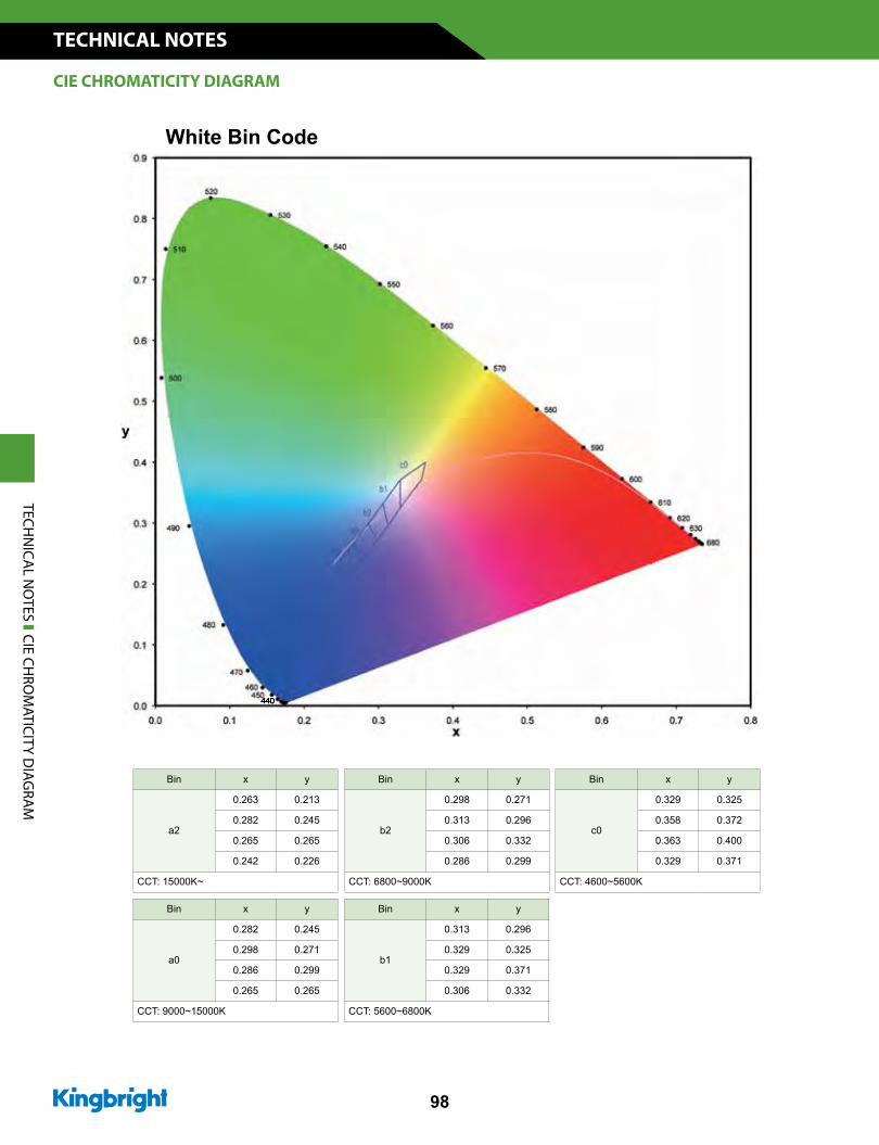
Bin x y
a2
0.263 0.213
0.282 0.245
0.265 0.265
0.242 0.226
CCT: 15000K~
Bin x y
b2
0.298 0.271
0.313 0.296
0.306 0.332
0.286 0.299
CCT: 6800~9000K
Bin x y
a0
0.282 0.245
0.298 0.271
0.286 0.299
0.265 0.265
CCT: 9000~15000K
Bin x y
c0
0.329 0.325
0.358 0.372
0.363 0.400
0.329 0.371
CCT: 4600~5600K
Bin x y
b1
0.313 0.296
0.329 0.325
0.329 0.371
0.306 0.332
CCT: 5600~6800K
CIE CHROMATICITY DIAGRAM
TECHN
ICAL N
OTES CIE CH
ROM
ATICITY DIAG
RAM
www.KingbrightUSA.com
TECHNICAL NOTES
99
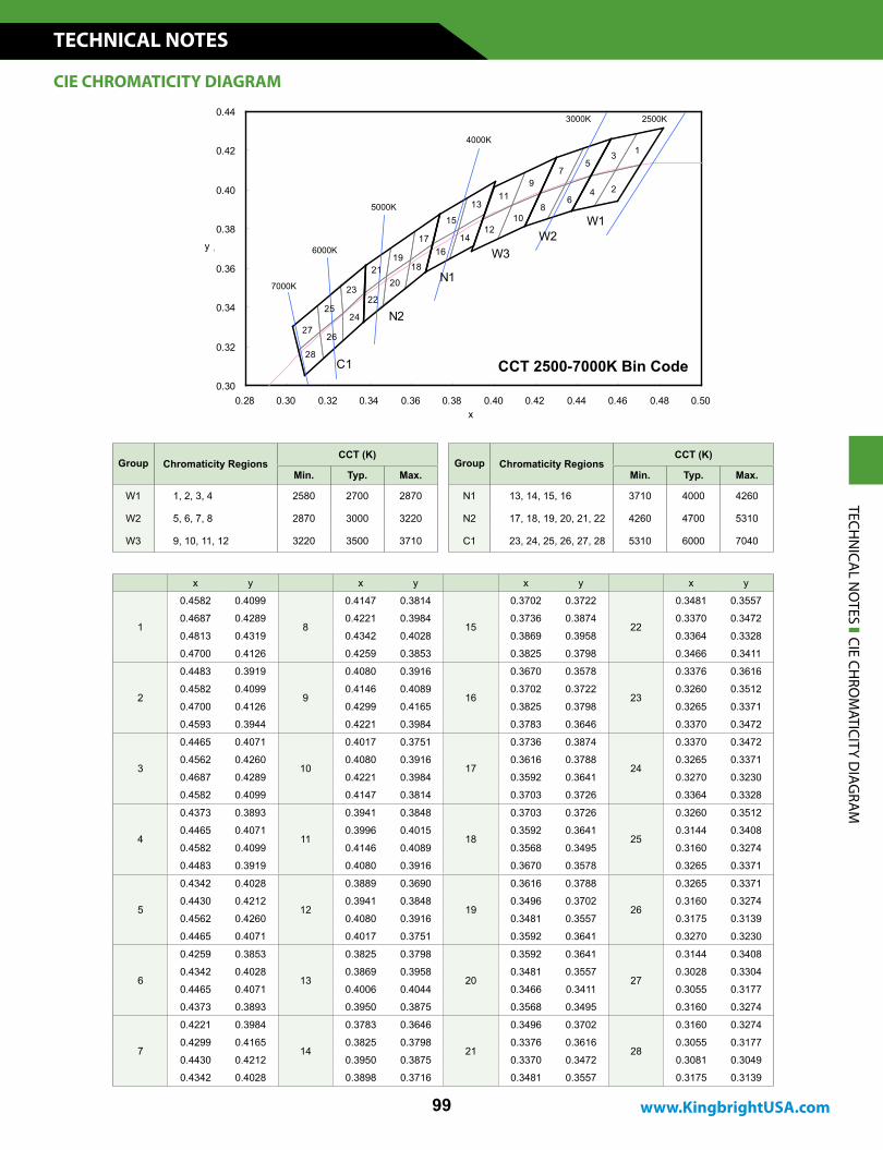
Group Chromaticity RegionsCCT (K)
Min. Typ. Max.
W1 1, 2, 3, 4 2580 2700 2870
W2 5, 6, 7, 8 2870 3000 3220
W3 9, 10, 11, 12 3220 3500 3710
x y x y x y x y
1
0.4582 0.4099
8
0.4147 0.3814
15
0.3702 0.3722
22
0.3481 0.3557
0.4687 0.4289 0.4221 0.3984 0.3736 0.3874 0.3370 0.3472
0.4813 0.4319 0.4342 0.4028 0.3869 0.3958 0.3364 0.3328
0.4700 0.4126 0.4259 0.3853 0.3825 0.3798 0.3466 0.3411
2
0.4483 0.3919
9
0.4080 0.3916
16
0.3670 0.3578
23
0.3376 0.3616
0.4582 0.4099 0.4146 0.4089 0.3702 0.3722 0.3260 0.3512
0.4700 0.4126 0.4299 0.4165 0.3825 0.3798 0.3265 0.3371
0.4593 0.3944 0.4221 0.3984 0.3783 0.3646 0.3370 0.3472
3
0.4465 0.4071
10
0.4017 0.3751
17
0.3736 0.3874
24
0.3370 0.3472
0.4562 0.4260 0.4080 0.3916 0.3616 0.3788 0.3265 0.3371
0.4687 0.4289 0.4221 0.3984 0.3592 0.3641 0.3270 0.3230
0.4582 0.4099 0.4147 0.3814 0.3703 0.3726 0.3364 0.3328
4
0.4373 0.3893
11
0.3941 0.3848
18
0.3703 0.3726
25
0.3260 0.3512
0.4465 0.4071 0.3996 0.4015 0.3592 0.3641 0.3144 0.3408
0.4582 0.4099 0.4146 0.4089 0.3568 0.3495 0.3160 0.3274
0.4483 0.3919 0.4080 0.3916 0.3670 0.3578 0.3265 0.3371
5
0.4342 0.4028
12
0.3889 0.3690
19
0.3616 0.3788
26
0.3265 0.3371
0.4430 0.4212 0.3941 0.3848 0.3496 0.3702 0.3160 0.3274
0.4562 0.4260 0.4080 0.3916 0.3481 0.3557 0.3175 0.3139
0.4465 0.4071 0.4017 0.3751 0.3592 0.3641 0.3270 0.3230
6
0.4259 0.3853
13
0.3825 0.3798
20
0.3592 0.3641
27
0.3144 0.3408
0.4342 0.4028 0.3869 0.3958 0.3481 0.3557 0.3028 0.3304
0.4465 0.4071 0.4006 0.4044 0.3466 0.3411 0.3055 0.3177
0.4373 0.3893 0.3950 0.3875 0.3568 0.3495 0.3160 0.3274
7
0.4221 0.3984
14
0.3783 0.3646
21
0.3496 0.3702
28
0.3160 0.3274
0.4299 0.4165 0.3825 0.3798 0.3376 0.3616 0.3055 0.3177
0.4430 0.4212 0.3950 0.3875 0.3370 0.3472 0.3081 0.3049
0.4342 0.4028 0.3898 0.3716 0.3481 0.3557 0.3175 0.3139
TECHN
ICAL N
OTES CIE CH
ROM
ATICITY DIAG
RAM
CIE CHROMATICITY DIAGRAM
CCT 2500-7000K Bin Code
Group Chromaticity RegionsCCT (K)
Min. Typ. Max.
N1 13, 14, 15, 16 3710 4000 4260
N2 17, 18, 19, 20, 21, 22 4260 4700 5310
C1 23, 24, 25, 26, 27, 28 5310 6000 7040
x
0.30
0.32
0.34
0.36
0.38
0.40
0.42
0.44
0.28 0.30 0.32 0.34 0.36 0.38 0.40 0.42 0.44 0.46 0.48 0.50x
y
2500 K3000 K
4000 K
5000 K
6000 K
7000 K
1
2
3
4
5
6
7
8
9
10
11
12
13
14
15
1617
1819
2021
2223
2425
2627
28
W1W2
W3
N1
N2
C1
y
x
7000K
6000K
5000K
4000K
3000K 2500K
CCT 2500-7000K Bin Code

Kingbright o�ers full custom LED options in package with your desired shape, form, color that will further enhance your design solutions. If you have further LED design objectives or specialized requirement to meet, please contact us at 909-468-0500 or email to [email protected]
For comprehensive product selections, please visit our online store at www.KingbrightUSA.com ,a streamlined process operating 24/7 online.