68” extra 300s - huawei modelshuaweimodels.com/mv/68inch extra 300s manual.pdf · congratulations...
TRANSCRIPT

1
Huawei Models
68” Extra 300S Instruction Manual

2
Congratulations and thank you for purchasing Huawei Models 68” Extra 300S. Our Extra was designed with 840 sq. inches of wing area while keep the total weight to a minimum. The light weight gives you sense of stability. Besides, you will find it simple to assemble. Huawei Models has long being developing and manufacturing R/C models. The products feature high quality and excellent performance. SPECIFICATIONS Wing Span Fuselage length: Main wing area: Weight: Wing loading: Recommended engine: Construction: Plug-in Wings: Plug-in Horizontal Stabs Engine Right Thrust Engine Down Thrust Elevator High Rates Elevator Low rates Aileron High Rates Aileron Low Rates Rudder Rates
1750 mm (68 inch) 1490mm (59 inch) 54 sq. dm (840 sq. inch) 2500g (without engine and R/C control devices, all accessories included) 80-85g/sq.dm 23cc-40cc gasoline engine Painted Fiberglass fuselage, Covered Balsa sheet wings with Foam inside. Carbon Spar Tubes Carbon Spar Tubes 1 Degrees to 2 Degrees 1 Degrees to 1.5 Degree 30 degrees Up and Down To Suit 30 Degrees Up and Down 20 Degrees Up and Down 35 Degrees
Read the instruction and study the parts and photos carefully before starting. The instruction will guide you to assemble all the major elements. Let’s go together on an enjoyable journey!
3
Table of contents Chapter 1 – Parts Inventory Chapter 2 – Landing Gear and Tail Wheel Assemblies Chapter 3 – Canopy Hatch and Cowling installation Chapter 4 – Wings installation Chapter 5 – Tail installation Chapter 6 – Horizontal stabilizers and elevators installation Chapter 7 – Final Inspection and Pre-Flight Additional items needed to complete this aircraft, which are not included:
An engine, within the recommended ranged, and propeller 6 channel computer radio and receiver recommended Batteries and switches (with regulators if using Ion batteries) Two aileron servos rated at least at 4.5kg.cm(60oz.inch) of torque Two elevator servos rated at least at 5kg.cm(70oz.inch) of torque One rudder servo rated at least at 6.5kg.cm(90oz.inch)oz of torque
(9kg.cm(130oz.inch) recommended) One throttle servo with push rod and links One optional choke servo with push rod and links One fueling dot or fueling device 2 to 3 feet of fuel tubing 3 inch spinner 30 to 45 minute epoxy CA glue Various modeling tools for assembly

4
Chapter 1: Parts Inventory Inside the Extra kits you will find 1 fuselage, 2 wings and 7 accessories bags. Please ensure your kit is complete:
1 Fuselage , 1 Canopy fuselage access hatch, 1 Rudder & 1 Fiberglass Cowl Main Wings (1 right and 1 left) 2 Horizontal stabilizers (1 right and 1 left) & 2 Elevators (1 right and 1 left)
1 Pair of fiberglass wheel pants & 1pair of landing gears
Wheel pants 2 PCS
Landing Gear 2 PCS
1 Carbon fiber wing tube 22mm, 1 Carbon fiber stabilizer tube 14mm and 2 short
fiberglass tubes 8mm
Accessory bag 1
Pivot & Round Hinges 22 PCS
Accessory bag 2
Horn connecter sets 4 PCS
M3x40mm screws 4PCS
Metal horns 4 sets
M2x12 screw and nuts 16 PCS

5
Accessory bag 3 As shown in the picture on the left.
1 Fuel tank
Accessory bag 4
2 wheels
2 sets
Accessory bag 5
Rudder connect set As show in the picture on the left.

6
Accessory bag 6
PA3.5x12mm self-tapping screws 20 PCS
PA4x12 mm self-tapping screws 10 PCS
PA3x12 mm self-tapping screws 10PCS
Aluminum nuts 4 PCS
M4x20 screw 6PCS
M4x16 screw 2PCS
Ф4 Plywood washer 6 PCS
Ф4 washers 10 PCS
Ф3 washers 10 PCS
Accessory bag 7
1 landing tail wheel sets As shown on the picture on the left.
If any of these parts are missing, please contact us immediately!

7
Chapter 2: Landing Gear and Tail Wheel Assemblies All parts of landing gear:
Steps of assembling landing gear: 1. Drill a 1.5mm small hole on the
plywood of the pant for the M3x12 wood screw. The screw is used to lock the pant on the gear.
2. Fasten the axles to the main landing gear with the lock nuts. Use care when tightening the lock nuts. If over tightened it can damage the composite landing gear and cause it to fail. Only tighten enough to lock the axle firmly in place and not rotate. 3. Lock pant on the landing gear with M3x12mm wood screw
8
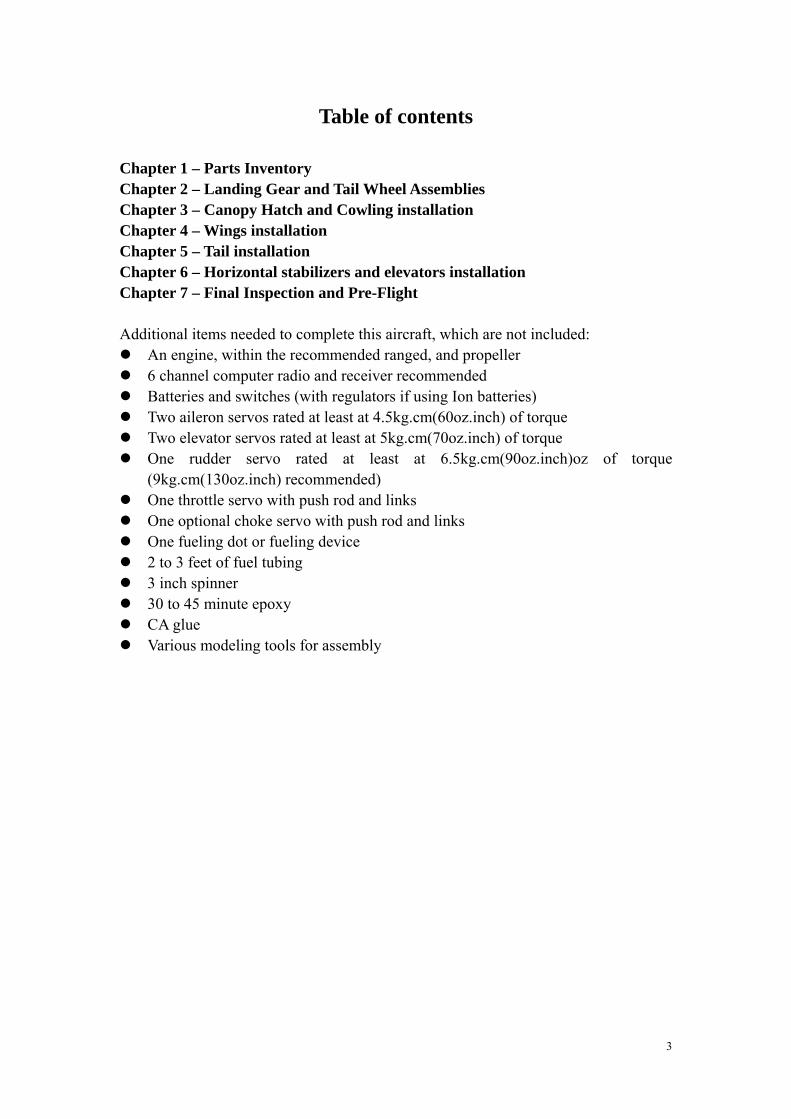
4. Fasten the wheel to the pants. 5. Please make sure that there is a piece of nylon tubing to the inside of each axle. This works as a spacer preventing the wheels from moving side-to-side and making contact against the inside of the wheel pants. 6. Install the landing gear to the fuselage with the 3 M4x20mm screws and flat washers.

9
Assembling Tail Wheel All parts of tail wheel:
Steps of assembling tail wheel 1. Widen three holes on the tail of fuselage to fit the screw (2.5mm). 2. Fasten the tail wheel to fuselage with 3 self-tapping screws and flat washers. 3. Please make sure that tail wheel lines up with centerline.

10
Chapter 3: Canopy Hatch and Cowling
1. Test fit and install Canopy Hatch on the fuselage using self-tapping screws.
2. For the cowling, test fit cowl on the fuselage. Drill holes at regular distance. 3. Remove the cowl and drill the holes to the size of the screws. 4. If necessary, apply some CA glue to the inner side of the hole on the fuselage to make the hole harder.

11
Chapter 4 – Wings installation 1. Now were going to prep the hinges for installation. Take a small drop of oil and place it in each of the pivot points of your hinges. The oil prevents excess epoxy from bonding the joint.
2. There are 5 holes on each aileron for
the hinges. Find out the holes under cover and cut the cover.
3. Working with one panel and control surface at a time, apply epoxy into the hinge holes of the trailing edge. Apply epoxy to one side of the hinges and insert them into the holes.
4. Carefully insert the control surface into the hinges and butt the two surfaces together. Move the surface up and down a couple of times to make sure all the hinges are aligned correctly and the desired throw is attained. 35 degrees for ailerons and 45 degrees for all others

12
5. Use some masking tape to hold the surfaces together and let cure for at least eight hours. Repeat these steps until all of the surfaces are epoxied in place
6. Install horns and connector of aileron and elevators as the pictures below Parts list as follows:
7. Remove the cover on the servo position. Install the servo into it.

13
8. Place the horn on the aileron and fix it with screws. Connect servo and horn with connectors as in the picture.
9. Insert the carbon tube to the fuselage. There are two holes in the fuselage for you to adjust centre of gravity.
10.Cut the cover of the wing tube and servo line via.

14
11. Lock the wings with two aluminum nuts, don’t forget the plywood washers and flat washers.
Chapter 5 – Tail installation 1. The structure of the horns on the rudder.
2. Drill two Ф3 holes at the bottom of the rudder.
3. Fix the horn to the rudder with screws as showed in the picture:

15
4. Install connectors to the servo.
5. install the servos into the fuselage.
6. Drill three holes on the bottom of the fuselage.
7. Find the place for connectors on the rudder.

16
8. Drill holes on the rudders as marked.
9. Connect the rudder with fuselage.
10. Connect the horns with servo with connectors and flexible stainless steel string as shown in the picture.
17
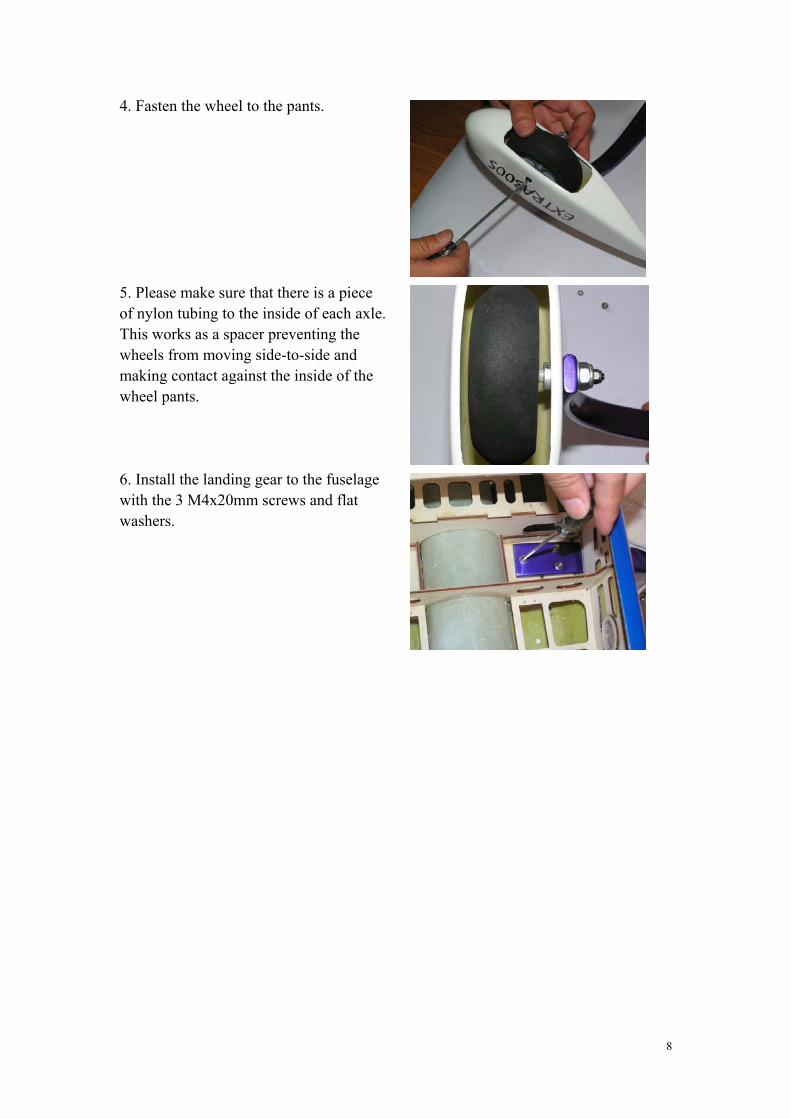
11. Connect tail wheel with rudder by two springs.
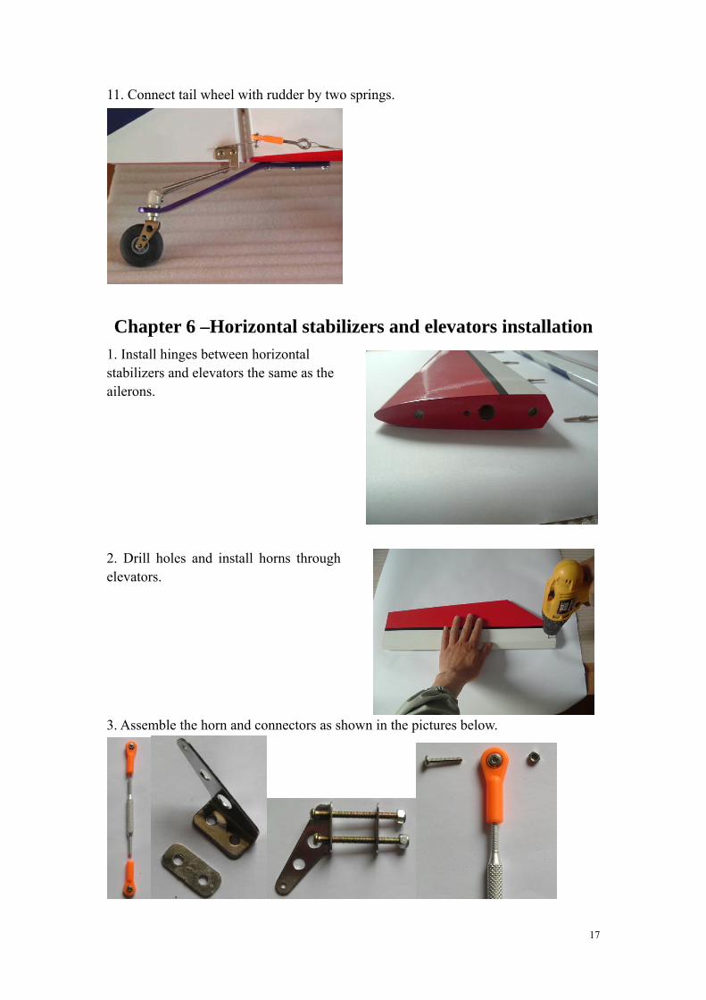
Chapter 6 –Horizontal stabilizers and elevators installation 1. Install hinges between horizontal stabilizers and elevators the same as the ailerons.
2. Drill holes and install horns through elevators.
3. Assemble the horn and connectors as shown in the pictures below.

18
4. Insert one 14mm and two 8mm carbon tubes into fuselage.
5. Apply CA glue to fix two 8mm short carbon tube.
6. Insert horizontal stabilizers into 14mm carbon tube, lock it with M4 screws. Plywood washer and flat washer are needed.

19
Chapter7 – Final Inspection and Pre-Flight
Welcome to the final chapter prior to your maiden flight. We hope you have enjoyed assembling your Extra300. This model aircraft can be dangerous to the pilot, observers, and property if not maintained properly or flown safely. Novice pilots should solicit the help of experienced R/C modelers before attempting to start or fly this aircraft. Lets go over the airframe and perform a pre-flight to make sure everything is in order.
Inspect the airframe for any visible damage and loose covering that may have occurred during assembly.
Inspect the main landing gear and tail wheel assembly. Ensure all mounting hardware and collars are fastened properly.
Inspect your engine installation and cowl to ensure all screws are tight and the muffler is firmly mounted in place. Check the engine and muffler for possible contact with the cowl. Inspect ignition module and spark plug wire for proper mounting. Check propeller and spinner to ensure they are both secure.
Inspect the inside of the fuselage to ensure your batteries, switches, regulators (if equipped), fuel tank and lines are securely fastened. Check aluminum screws on the wings to ensure they are in place and secured.
Inspect all control surfaces and control surface hardware. Gently tug on each surface to make sure the hinges are properly bonded. Check the horizontal stabilizer fasteners and ensure they’re in place and secured.
Check all servos for mounting screws. Check servo arm mounting screws and inspect that the links have been secured with lock nuts.
Fill fuel tank and inspect for any leaks. Check your batteries in both your aircraft and radio to ensure they are fully
charged Turn on radio to inspect all controls for binding, proper direction and throw while
on high rates. Re-check CG. It should be anywhere from 10cm to 14cm depending on your

20
flying style. You also can changer the center gravity by choosing the other main wing tube hole.
Secure aircraft using a buddy or hold down and start motor according to manufacturers guidelines. Don’t forget to lower your throttle prior to ignition.
Perform a proper range check with the engine running using your radio manufacturers instructions.
Make sure you go back to low rates for your maiden takeoff and enjoy! This concludes your pre-flight checks. After your maiden flight, repeat these steps to perform a post flight to ensure nothing has loosened. It’s always a good habit to use a checklist like this one to go over your aircraft prior to the first flight of the day. Good luck with your flying!