6800-22 ultra tugger cable puller and pulling package ultra tugger ® cable puller and pulling...
TRANSCRIPT
SERVICE MANUAL
Read and understand all of the instructions and safety information in this manual before operating or servicing this tool.
Register this product at www.greenlee.com99966174 REV 4 © 2015 Greenlee Textron Inc. 8/15
6800-22 Ultra Tugger® Cable Puller and Pulling Package
Serial Code ADB
6800-22 Ultra Tugger® Cable Puller and Pulling Package
Greenlee / A Textron Company 4455 Boeing Dr. • Rockford, IL 61109-2988 USA • 815-397-70702
Safety
Safety is essential in the use and maintenance of Greenlee tools and equipment. This service manual and any markings on the tools provide information for avoiding hazards and unsafe practices related to use of this tool. Observe all of the safety information provided.
Do not operate this tool unless fully trained to do so, or under trained supervision.
Purpose of this Manual
This manual is intended to familiarize authorized Greenlee service center personnel with the safe operation and maintenance procedures for the Greenlee 6800-22 Ultra Tugger® cable puller.
Keep this manual available to all personnel.
Replacement manuals are available upon request at no charge at www.greenlee.com.
Other Publications
Instruction Manual: 99938502 (IM 1529)
All specifications are nominal and may change as design improvements occur. Greenlee Textron shall not be liable for damages resulting from misapplication or misuse of its products.
Ultra Tugger is a registered trademark of Textron Innovations Inc.
Loctite and 242 are registered trademarks of Loctite Corporation.
Texaco is a registered trademark of Texaco Inc.
KEEP THIS MANUAL
Table of Contents
Safety ............................................................................ 2
Purpose of this Manual ................................................. 2
Important Safety Information ..................................... 3-5
Grounding Instructions .................................................. 6
Operation ....................................................................... 7
Maintenance ............................................................... 8-9
Exploded Views and Parts Lists
Ultra Tugger (with wiring diagram) ...................... 10-11
Gearmotor (50079239) ........................................ 12-13
Motor (50079220) .................................................... 14
Force Gauge ............................................................ 15
Accessories ............................................................ 16-22
6800-22 Ultra Tugger® Cable Puller and Pulling Package
Greenlee / A Textron Company 4455 Boeing Dr. • Rockford, IL 61109-2988 USA • 815-397-70703
IMPORTANT SAFETY INFORMATION
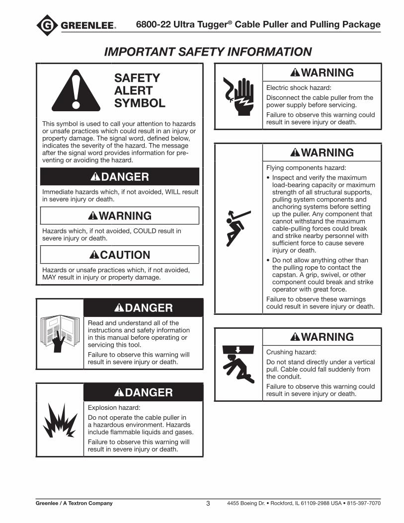
SAFETY ALERT SYMBOL
This symbol is used to call your attention to hazards or unsafe practices which could result in an injury or property damage. The signal word, defined below, indicates the severity of the hazard. The message after the signal word provides information for pre-venting or avoiding the hazard.
Immediate hazards which, if not avoided, WILL result in severe injury or death.
Hazards which, if not avoided, COULD result in severe injury or death.
Hazards or unsafe practices which, if not avoided, MAY result in injury or property damage.
Read and understand all of the instructions and safety information in this manual before operating or servicing this tool.
Failure to observe this warning will result in severe injury or death.
Explosion hazard:
Do not operate the cable puller in a hazardous environment. Hazards include flammable liquids and gases.
Failure to observe this warning will result in severe injury or death.
Electric shock hazard:
Disconnect the cable puller from the power supply before servicing.
Failure to observe this warning could result in severe injury or death.
Flying components hazard:
• Inspect and verify the maximum load-bearing capacity or maximum strength of all structural supports, pulling system components and anchoring systems before setting up the puller. Any component that cannot withstand the maximum cable-pulling forces could break and strike nearby personnel with sufficient force to cause severe injury or death.
• Do not allow anything other than the pulling rope to contact the capstan. A grip, swivel, or other component could break and strike operator with great force.
Failure to observe these warnings could result in severe injury or death.
Crushing hazard:
Do not stand directly under a vertical pull. Cable could fall suddenly from the conduit.
Failure to observe this warning could result in severe injury or death.
6800-22 Ultra Tugger® Cable Puller and Pulling Package
Greenlee / A Textron Company 4455 Boeing Dr. • Rockford, IL 61109-2988 USA • 815-397-70704
IMPORTANT SAFETY INFORMATION
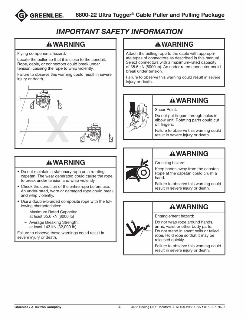
Flying components hazard:
Locate the puller so that it is close to the conduit. Rope, cable, or connectors could break under tension, causing the rope to whip violently.
Failure to observe this warning could result in severe injury or death.
• Do not maintain a stationary rope on a rotating capstan. The wear generated could cause the rope to break under tension and whip violently.
• Check the condition of the entire rope before use. An under-rated, worn or damaged rope could break and whip violently.
• Use a double-braided composite rope with the fol-lowing characteristics:
– Maximum Rated Capacity: at least 35.6 kN (8000 lb)
– Average Breaking Strength: at least 143 kN (32,000 lb)
Failure to observe these warnings could result in severe injury or death.
Attach the pulling rope to the cable with appropri-ate types of connectors as described in this manual. Select connectors with a maximum-rated capacity of 35.6 kN (8000 lb). An under-rated connector could break under tension.
Failure to observe this warning could result in severe injury or death.
Shear Point:
Do not put fingers through holes in elbow unit. Rotating parts could cut off fingers.
Failure to observe this warning could result in severe injury or death.
Crushing hazard:
Keep hands away from the capstan. Rope at the capstan could crush a hand.
Failure to observe this warning could result in severe injury or death.
Entanglement hazard:
Do not wrap rope around hands, arms, waist or other body parts. Do not stand in spent coils or tailed rope. Hold rope so that it may be released quickly.
Failure to observe this warning could result in severe injury or death.
6800-22 Ultra Tugger® Cable Puller and Pulling Package
Greenlee / A Textron Company 4455 Boeing Dr. • Rockford, IL 61109-2988 USA • 815-397-70705
IMPORTANT SAFETY INFORMATION
Entanglement hazard:
• Do not operate the cable puller while wearing loose-fitting clothing.
• Retain long hair.
Failure to observe this warning could result in severe injury or death.
Wear eye protection when using this tool. Failure to wear eye protection could result in severe eye injury from flying debris.
Tipping hazard:
When using the wheeled carriage to transport the Ultra Tugger:
• Keep personnel out of the path of transport.
• Evaluate the terrain over which the carriage is to move. If in doubt, obtain additional help and move the carriage slowly.
• Do not transport over inclines of more than 10°.
• Do not transport the carriage with boom tubes longer than the supplied 3' and 4' tubes.
10°
Failure to observe this warning could result in severe injury or death.
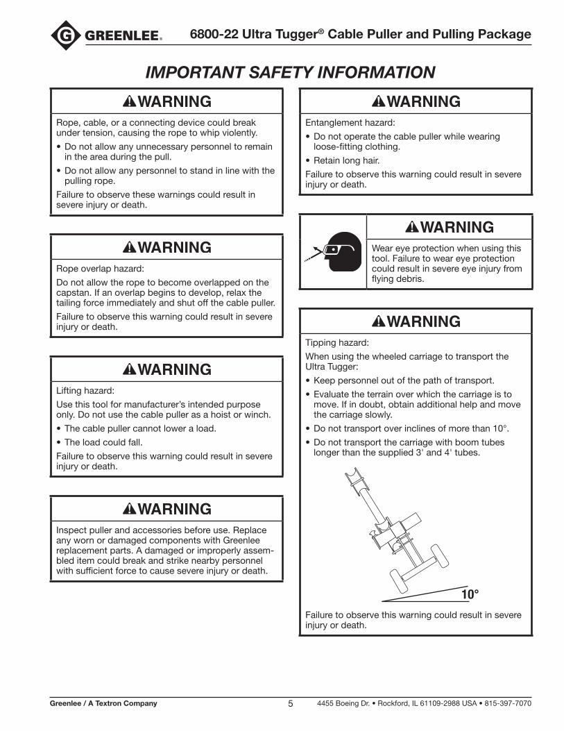
Rope, cable, or a connecting device could break under tension, causing the rope to whip violently.
• Do not allow any unnecessary personnel to remain in the area during the pull.
• Do not allow any personnel to stand in line with the pulling rope.
Failure to observe these warnings could result in severe injury or death.
Rope overlap hazard:
Do not allow the rope to become overlapped on the capstan. If an overlap begins to develop, relax the tailing force immediately and shut off the cable puller.
Failure to observe this warning could result in severe injury or death.
Lifting hazard:
Use this tool for manufacturer’s intended purpose only. Do not use the cable puller as a hoist or winch.
• The cable puller cannot lower a load.
• The load could fall.
Failure to observe this warning could result in severe injury or death.
Inspect puller and accessories before use. Replace any worn or damaged components with Greenlee replacement parts. A damaged or improperly assem-bled item could break and strike nearby personnel with sufficient force to cause severe injury or death.
6800-22 Ultra Tugger® Cable Puller and Pulling Package
Greenlee / A Textron Company 4455 Boeing Dr. • Rockford, IL 61109-2988 USA • 815-397-70706
Grounding Instructions
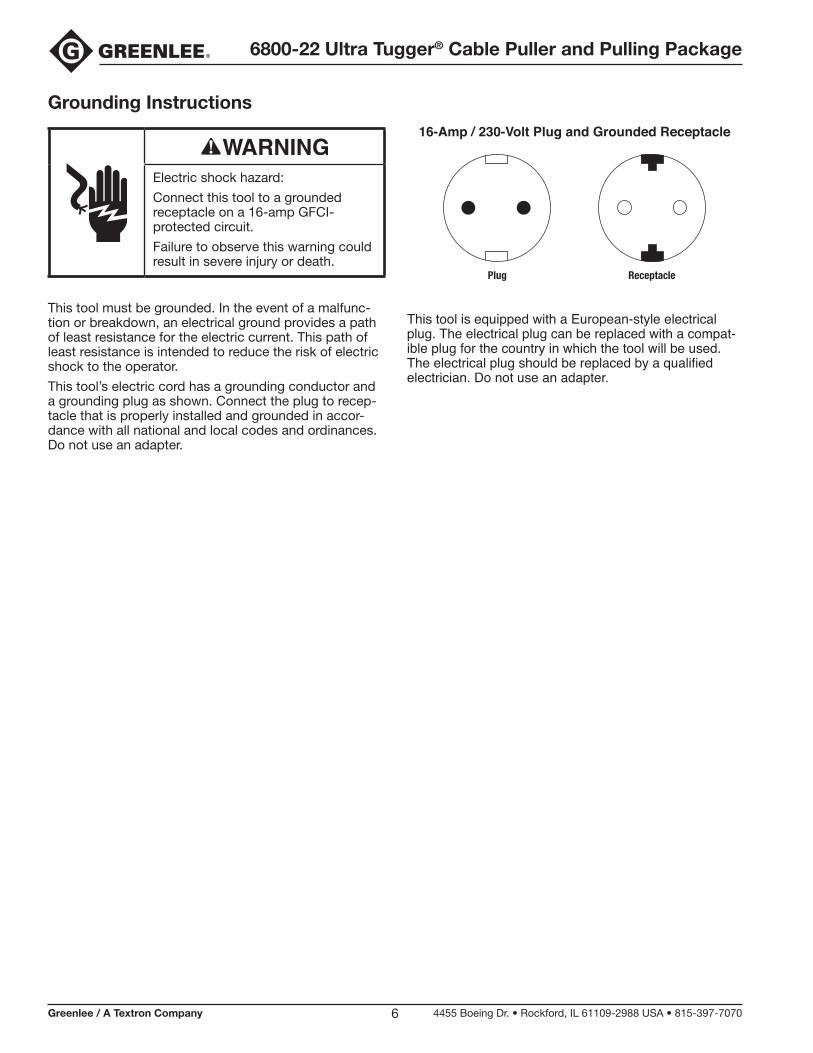
Electric shock hazard:
Connect this tool to a grounded receptacle on a 16-amp GFCI-protected circuit.
Failure to observe this warning could result in severe injury or death.
This tool must be grounded. In the event of a malfunc-tion or breakdown, an electrical ground provides a path of least resistance for the electric current. This path of least resistance is intended to reduce the risk of electric shock to the operator.
This tool’s electric cord has a grounding conductor and a grounding plug as shown. Connect the plug to recep-tacle that is properly installed and grounded in accor-dance with all national and local codes and ordinances. Do not use an adapter.
16-Amp / 230-Volt Plug and Grounded Receptacle
ReceptaclePlug
This tool is equipped with a European-style electrical plug. The electrical plug can be replaced with a compat-ible plug for the country in which the tool will be used. The electrical plug should be replaced by a qualified electrician. Do not use an adapter.
6800-22 Ultra Tugger® Cable Puller and Pulling Package
Greenlee / A Textron Company 4455 Boeing Dr. • Rockford, IL 61109-2988 USA • 815-397-70707
Operation
1. Fish the rope through the conduit.
2. Set up the cable puller. See “Typical Setups” illustrations and instructions in Instruction Manual 99938502 (IM 1529).
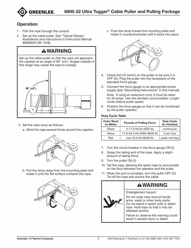
Set up the cable puller so that the rope will approach the capstan at an angle of 90° (±5°). Angles outside of this range may cause the rope to overlap.
90° (±5°)
3. Set the rope ramp as follows:
a. Wind the rope several times around the capstan.
b. Pull the ramp away from the mounting plate and rotate it until the flat surface contacts the rope.
c. Push the ramp toward the mounting plate and rotate it counterclockwise until it locks into place.
4. Check the I/O switch on the puller to be sure it is OFF (O). Plug the puller into the receptacle of the standard force gauge.
5. Connect the force gauge to an appropriate power supply (see “Grounding Instructions” in this manual).
Note: If using an extension cord, it must be rated for 20 amps. Use the shortest cord possible. Longer cords reduce puller speed.
6. Position the force gauge so that it can be monitored by the puller operator.
Duty Cycle Table
Color Band on Meter Pounds of Pulling Force Duty Cycle
(in minutes)
Green 0–17.8 kN (0–4000 lb) continuous
Yellow 17.8–35.6 kN (4000–8000 lb) 5 per hour
Red over 35.6 kN (8000 lb) puller will stop
7. Turn the circuit breaker in the force gauge ON (I).
8. Grasp the tailing end of the rope. Apply a slight amount of tailing force.
9. Turn the puller ON (I).
10. Tail the rope, allowing the spent rope to accumulate on the floor between the operator and the puller.
11. When the pull is complete, turn the puller OFF (O). Tie off the rope and anchor the cable.
Entanglement hazard:
Do not wrap rope around hands, arms, waist or other body parts. Do not stand in spent coils or tailed rope. Hold rope so that it may be released quickly.
Failure to observe this warning could result in severe injury or death.
6800-22 Ultra Tugger® Cable Puller and Pulling Package
Greenlee / A Textron Company 4455 Boeing Dr. • Rockford, IL 61109-2988 USA • 815-397-70708
Maintenance
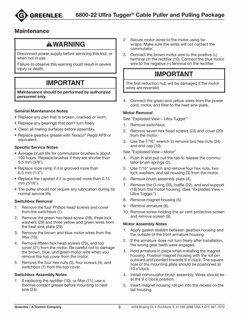
Disconnect power supply before servicing this tool, or when not in use.Failure to observe this warning could result in severe injury or death.
Maintenance should be performed by authorized personnel only.
General Maintenance Notes
• Replace any part that is broken, cracked or worn.
• Replace any bearings that don’t turn freely.
• Clean all mating surfaces before assembly.
• Replace gearbox grease with Texaco® Regal AFB or equivalent.
Specific Service Notes
• Average brush life for commutator brushes is about 100 hours. Replace brushes if they are shorter than 9.5 mm (3/8").
• Replace rope ramp if it is grooved more than 6.5 mm (1/4").
• Replace the capstan if it is grooved more than 0.15 mm (1/16").
• The puller should not require any lubrication during its normal service life.
Switchbox Removal
1. Remove the four Phillips head screws and cover from the switchbox (1).
2. Remove the green hex head screw (28), three lock washers (29) and three yellow and green wires from the heat sink plate (24).
3. Remove the brown and blue motor wires from the filter (10).
4. Remove fifteen hex head screws (23), and top cover (21) from the motor. Be careful not to damage the brown, blue, and green motor wire when you remove the top cover from the motor.
5. Remove the four hex nuts (5), four screws (4), and switchbox (1) from the top cover.
Switchbox Assembly Notes
1. If replacing the rectifier (10), or filter (11), use a thermal contact grease before mounting to heat sink (24).
2. Secure motor wires to the motor using tie-wraps. Make sure the wires will not contact the commutator.
3. Connect the brown motor wire to the positive (+) terminal on the rectifier (10). Connect the blue motor wire to the negative (–) terminal on the rectifier.
The first reduction hub will be damaged if the motor wires are reversed.
4. Connect the green and yellow wires from the power cord, motor, and filter to the heat sink plate.
Motor Removal
See “Exploded View —Ultra Tugger”
1. Remove switchbox.
2. Remove seven hex head screws (23) and cover (20) from the motor.
3. Use the 7/16" wrench to remove two hex nuts (34) and end cap (19).
See “Exploded View—Motor”
4. Push in and pull out the tab to release the commu-tator brush springs (2).
5. Use 7/16" wrench and remove four hex nuts, two lock washers, and tail housing (3) from the motor.
6. Remove brush assembly plate (4).
7. Remove the O-ring (35), baffle (22), and end support (18) from the motor housing. (See “Exploded View—Ultra Tugger.”)
8. Remove magnet housing (5).
9. Remove armature (6).
10. Remove screw holding the air vent protective screen and remove screen (9).
Motor Assembly Notes
1. Apply gasket sealant between gearbox housing and the outside of the front armature housing.
2. If the armature does not turn freely after installation, the wrong gear teeth were engaged.
3. Hold armature in place when installing the magnet housing. Position magnet housing with the roll pin outward and pointed towards 8 o’clock. The square hole of the mounting plate should be positioned at 10 o’clock.
4. Install commutator brush assembly. Wires should be at the 9 o’clock position.
5. Insert magnet housing roll pin into the recess on the tail housing.
6800-22 Ultra Tugger® Cable Puller and Pulling Package
Greenlee / A Textron Company 4455 Boeing Dr. • Rockford, IL 61109-2988 USA • 815-397-70709
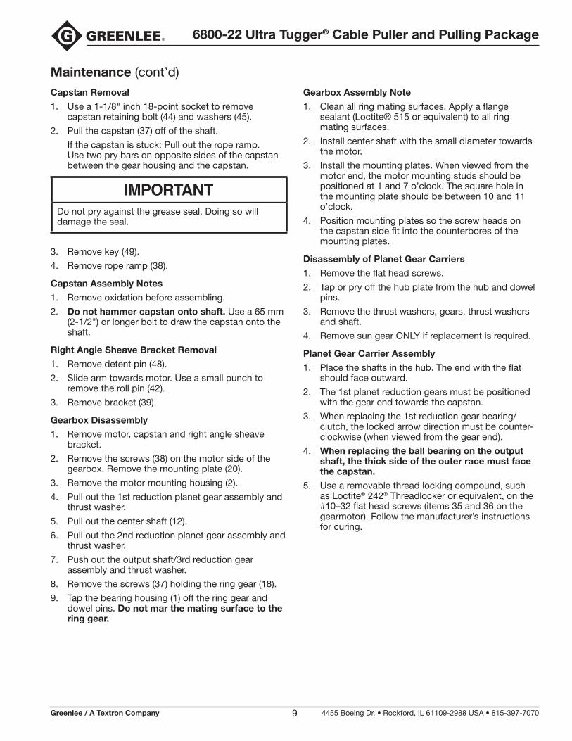
Maintenance (cont’d)Capstan Removal
1. Use a 1-1/8" inch 18-point socket to remove capstan retaining bolt (44) and washers (45).
2. Pull the capstan (37) off of the shaft.
If the capstan is stuck: Pull out the rope ramp. Use two pry bars on opposite sides of the capstan between the gear housing and the capstan.
Do not pry against the grease seal. Doing so will damage the seal.
3. Remove key (49).
4. Remove rope ramp (38).
Capstan Assembly Notes
1. Remove oxidation before assembling.
2. Do not hammer capstan onto shaft. Use a 65 mm (2-1/2") or longer bolt to draw the capstan onto the shaft.
Right Angle Sheave Bracket Removal
1. Remove detent pin (48).
2. Slide arm towards motor. Use a small punch to remove the roll pin (42).
3. Remove bracket (39).
Gearbox Disassembly
1. Remove motor, capstan and right angle sheave bracket.
2. Remove the screws (38) on the motor side of the gearbox. Remove the mounting plate (20).
3. Remove the motor mounting housing (2).
4. Pull out the 1st reduction planet gear assembly and thrust washer.
5. Pull out the center shaft (12).
6. Pull out the 2nd reduction planet gear assembly and thrust washer.
7. Push out the output shaft/3rd reduction gear assembly and thrust washer.
8. Remove the screws (37) holding the ring gear (18).
9. Tap the bearing housing (1) off the ring gear and dowel pins. Do not mar the mating surface to the ring gear.
Gearbox Assembly Note
1. Clean all ring mating surfaces. Apply a flange sealant (Loctite® 515 or equivalent) to all ring mating surfaces.
2. Install center shaft with the small diameter towards the motor.
3. Install the mounting plates. When viewed from the motor end, the motor mounting studs should be positioned at 1 and 7 o’clock. The square hole in the mounting plate should be between 10 and 11 o’clock.
4. Position mounting plates so the screw heads on the capstan side fit into the counterbores of the mounting plates.
Disassembly of Planet Gear Carriers
1. Remove the flat head screws.
2. Tap or pry off the hub plate from the hub and dowel pins.
3. Remove the thrust washers, gears, thrust washers and shaft.
4. Remove sun gear ONLY if replacement is required.
Planet Gear Carrier Assembly
1. Place the shafts in the hub. The end with the flat should face outward.
2. The 1st planet reduction gears must be positioned with the gear end towards the capstan.
3. When replacing the 1st reduction gear bearing/clutch, the locked arrow direction must be counter-clockwise (when viewed from the gear end).
4. When replacing the ball bearing on the output shaft, the thick side of the outer race must face the capstan.
5. Use a removable thread locking compound, such as Loctite® 242® Threadlocker or equivalent, on the #10–32 flat head screws (items 35 and 36 on the gearmotor). Follow the manufacturer’s instructions for curing.
6800-22 Ultra Tugger® Cable Puller and Pulling Package
Greenlee / A Textron Company 4455 Boeing Dr. • Rockford, IL 61109-2988 USA • 815-397-707010
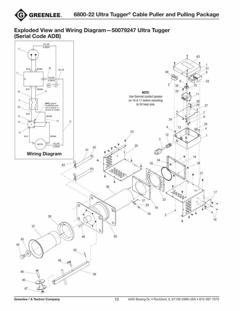
Exploded View and Wiring Diagram —50079247 Ultra Tugger (Serial Code ADB)
15
10
15
26
9
26 14
14 31
11
3
3028, 29BLUE BROWN
BLUE BROWN
BLUE
BROWN
YELLOW
& GREEN
YELLOW
& GREEN
YELLOW
& GREEN
BLUE
BROWN
NOTE: Connect the BROWN motorwire to positive (+) terminal on rectifier.
MOTOR
PE
Wiring Diagram
NOTE:Use thermal contact greaseon 10 & 11 before mounting
to 24 heat sink.
20
18
22
19
343534
21
17
16
36
50 5
29
37
38
62
41
44
45
42
43
48
49
40
46
47
39
42
23
3
I O
10
11
28
64
32
33
2829
13
1
9
63
51
27
67
24
12
4
1
425
52
51
6800-22 Ultra Tugger® Cable Puller and Pulling Package
Greenlee / A Textron Company 4455 Boeing Dr. • Rockford, IL 61109-2988 USA • 815-397-707011
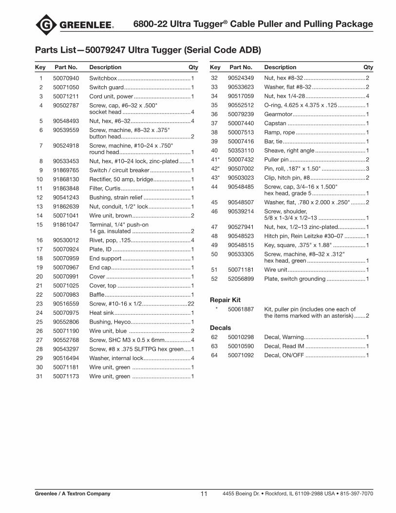
Parts List —50079247 Ultra Tugger (Serial Code ADB)
1 50070940 Switchbox .............................................1
2 50071050 Switch guard .........................................1
3 50071211 Cord unit, power ...................................1
4 90502787 Screw, cap, #6–32 x .500" socket head ..........................................4
5 90548493 Nut, hex, #6–32 .....................................4
6 90539559 Screw, machine, #8–32 x .375" button head...........................................2
7 90524918 Screw, machine, #10–24 x .750" round head ............................................1
8 90533453 Nut, hex, #10–24 lock, zinc-plated .......1
9 91869765 Switch / circuit breaker .........................1
10 91868130 Rectifier, 50 amp, bridge .......................1
11 91863848 Filter, Curtis ...........................................1
12 90541243 Bushing, strain relief .............................1
13 91862639 Nut, conduit, 1/2" lock ..........................1
14 50071041 Wire unit, brown ....................................2
15 91861047 Terminal, 1/4" push-on 14 ga. insulated ....................................2
16 90530012 Rivet, pop, .125.....................................4
17 50070924 Plate, ID ................................................1
18 50070959 End support ..........................................1
19 50070967 End cap .................................................1
20 50070991 Cover ....................................................1
21 50071025 Cover, top .............................................1
22 50070983 Baffle .....................................................1
23 90516559 Screw, #10-16 x 1/2 ............................22
24 50070975 Heat sink ...............................................1
25 90552806 Bushing, Heyco.....................................1
26 50071190 Wire unit, blue ......................................2
27 90552768 Screw, SHC M3 x 0.5 x 6mm ................4
28 90543297 Screw, #8 x .375 SLFTPG hex green ....1
29 90516494 Washer, internal lock .............................4
30 50071181 Wire unit, green ....................................1
31 50071173 Wire unit, green ....................................1
Key Part No. Description Qty Key Part No. Description Qty
32 90524349 Nut, hex #8-32 ......................................2
33 90533623 Washer, flat #8-32 .................................2
34 90517059 Nut, hex 1/4-28 .....................................4
35 90552512 O-ring, 4.625 x 4.375 x .125 .................1
36 50079239 Gearmotor .............................................1
37 50007440 Capstan ................................................1
38 50007513 Ramp, rope ...........................................1
39 50007416 Bar, tie ...................................................1
40 50353110 Sheave, right angle ...............................1
41* 50007432 Puller pin ...............................................2
42* 90507002 Pin, roll, .187" x 1.50" ...........................3
43* 90503023 Clip, hitch pin, #8 ..................................2
44 90548485 Screw, cap, 3/4–16 x 1.500" hex head, grade 5 .................................1
45 90548507 Washer, flat, .780 x 2.000 x .250" .........2
46 90539214 Screw, shoulder, 5/8 x 1-3/4 x 1/2–13 .............................1
47 90527941 Nut, hex, 1/2–13 zinc-plated.................1
48 90548523 Hitch pin, Rein Leitzke #30–07 .............1
49 90548515 Key, square, .375" x 1.88" ....................1
50 90533305 Screw, machine, #8–32 x .312" hex head, green ....................................1
51 50071181 Wire unit ................................................1
52 52056899 Plate, switch grounding ........................1
Repair Kit * 50061887 Kit, puller pin (includes one each of the items marked with an asterisk) .......2
Decals 62 50010298 Decal, Warning ......................................1
63 50010590 Decal, Read IM .....................................1
64 50071092 Decal, ON/OFF .....................................1
6800-22 Ultra Tugger® Cable Puller and Pulling Package
Greenlee / A Textron Company 4455 Boeing Dr. • Rockford, IL 61109-2988 USA • 815-397-707012
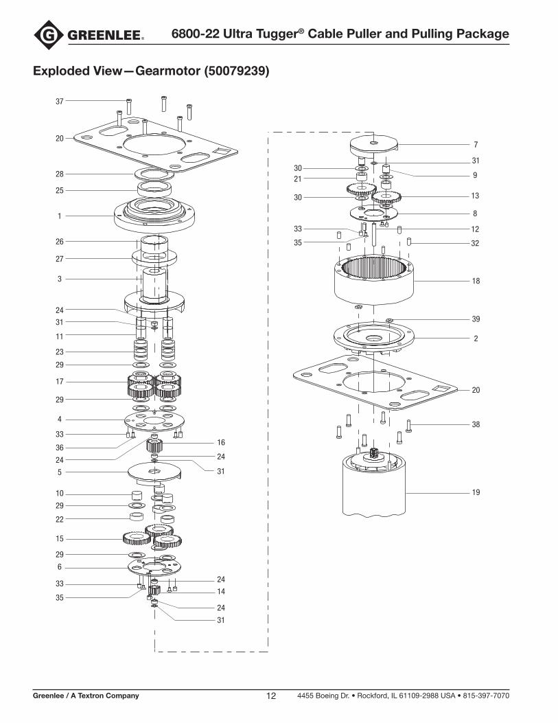
Exploded View —Gearmotor (50079239)
37
20
28
25
1
26
27
3
24
31
11
23
29
17
29
4
33
36
24
16
24
315
10
29
22
15
29
6
33 24
3524
31
7
33
35
313021
30
9
13
8
12
32
18
39
2
20
38
19
14
6800-22 Ultra Tugger® Cable Puller and Pulling Package
Greenlee / A Textron Company 4455 Boeing Dr. • Rockford, IL 61109-2988 USA • 815-397-707013
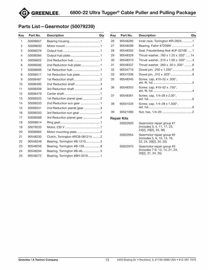
Parts List —Gearmotor (50079239)
1 50006657 Bearing housing ....................................1
2 50006630 Motor mount .........................................1
3 50006576 Output hub ............................................1
4 50006584 Output hub plate ...................................1
5 50006622 2nd Reduction hub ...............................1
6 50006592 2nd Reduction hub plate ......................1
7 50006606 1st Reduction hub ................................1
8 50006517 1st Reduction hub plate........................1
9 50006487 1st Reduction shaft ...............................2
10 50006495 2nd Reduction shaft .............................3
11 50006509 3rd Reduction shaft ..............................4
12 50006479 Center shaft ..........................................1
13 50006525 1st Reduction planet gear.....................2
14 50006533 2nd Reduction sun gear .......................1
15 50006541 2nd Reduction planet gear ...................3
16 50006550 3rd Reduction sun gear ........................1
17 50006568 3rd Reduction planet gear ....................4
18 50006614 Ring gear...............................................1
19 50079220 Motor, 230 V .........................................1
20 50006665 Motor mounting plate ...........................2
21 90548230 Clutch, Torrington #RCB-081214 .........2
22 90548248 Bearing, Torrington #B-1210.................3
23 90548256 Bearing, Torrington #B-128...................8
24 90548264 Bearing, Torrington #B-46.....................5
25 90548272 Bearing, Torrington #BH-3316 ..............1
Key Part No. Description Qty Key Part No. Description Qty
26 90548280 Inner race, Torrington #IR-2824 ............1
27 90548299 Bearing, Fafnir #7209W ........................1
28 90548302 Seal, Freudenberg-Nok #UF-0216E .....1
29 90548329 Thrust washer, .760 x 1.25 x .020" .....14
30 90548310 Thrust washer, .510 x 1.00 x .020" .......4
31 90548337 Thrust washer, .260 x .50 x .030" .........8
32 90534719 Dowel pin, .250 x 1.250" .......................6
33 90541036 Dowel pin, .312 x .625" .........................9
35 90548345 Screw, cap, #10–32 x .500", skt. flt. hd. .............................................5
36 90548353 Screw, cap, #10–32 x .750", skt. flt. hd. .............................................4
37 90548361 Screw, cap, 1/4–28 x 2.00", skt. hd. ..................................................6
38 90501535 Screw, cap, 1/4–28 x 1.500", skt. hd. ..................................................6
39 90521080 Nut, hex, 1/4–20 ...................................2
Repair Kits 50022920 Gearmotor repair group #1 (includes 3, 4, 11, 17, 23, 24[2], 29[2], 33, 36)
50022954 Gearmotor repair group #2 (includes 5, 6, 10, 15, 16, 22, 24, 29[2], 34, 35)
50022970 Gearmotor repair group #3 (includes 7-9, 13, 14, 21, 24, 30[2], 31, 34, 35)
6800-22 Ultra Tugger® Cable Puller and Pulling Package
Greenlee / A Textron Company 4455 Boeing Dr. • Rockford, IL 61109-2988 USA • 815-397-707014
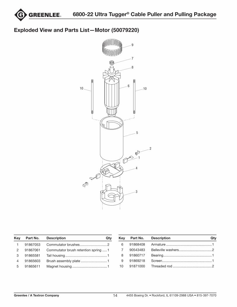
Exploded View and Parts List —Motor (50079220)
1
2
3
6
7
8
5
4
1010
9
1 91867053 Commutator brushes ............................2
2 91867061 Commutator brush retention spring .....1
3 91865581 Tail housing ...........................................1
4 91865603 Brush assembly plate ...........................1
5 91865611 Magnet housing ....................................1
Key Part No. Description Qty Key Part No. Description Qty
6 91868408 Armature ...............................................1
7 90543483 Belleville washers..................................2
8 91860717 Bearing ..................................................1
9 91869218 Screen ...................................................1
10 91871000 Threaded rod ........................................2
6800-22 Ultra Tugger® Cable Puller and Pulling Package
Greenlee / A Textron Company 4455 Boeing Dr. • Rockford, IL 61109-2988 USA • 815-397-707015
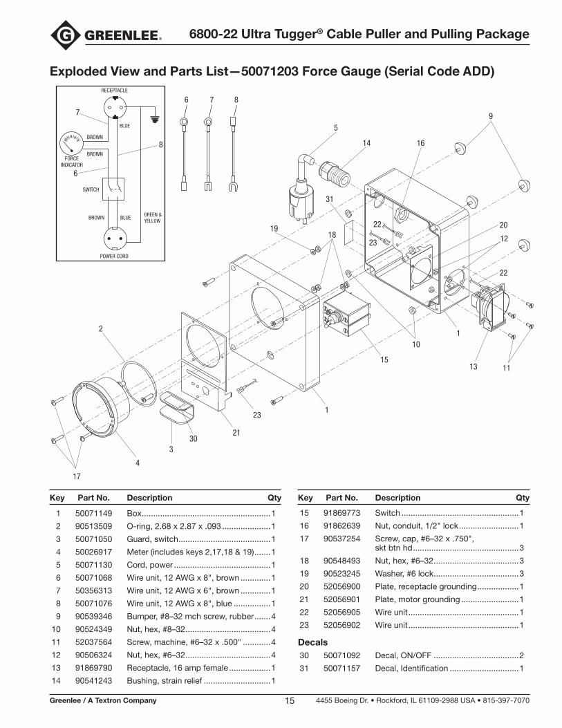
Exploded View and Parts List —50071203 Force Gauge (Serial Code ADD)
1 50071149 Box ........................................................1
2 90513509 O-ring, 2.68 x 2.87 x .093 .....................1
3 50071050 Guard, switch ........................................1
4 50026917 Meter (includes keys 2,17,18 & 19) .......1
5 50071130 Cord, power ..........................................1
6 50071068 Wire unit, 12 AWG x 8", brown .............1
7 50356313 Wire unit, 12 AWG x 6", brown .............1
8 50071076 Wire unit, 12 AWG x 8", blue ................1
9 90539346 Bumper, #8–32 mch screw, rubber .......4
10 90524349 Nut, hex, #8–32 .....................................4
11 52037564 Screw, machine, #6–32 x .500" ............4
12 90506324 Nut, hex, #6–32 .....................................4
13 91869790 Receptacle, 16 amp female ..................1
14 90541243 Bushing, strain relief .............................1
Key Part No. Description Qty Key Part No. Description Qty
15 91869773 Switch ...................................................1
16 91862639 Nut, conduit, 1/2" lock ..........................1
17 90537254 Screw, cap, #6–32 x .750", skt btn hd ..............................................3
18 90548493 Nut, hex, #6–32 .....................................3
19 90523245 Washer, #6 lock .....................................3
20 52056900 Plate, receptacle grounding ..................1
21 52056901 Plate, motor grounding .........................1
22 52056905 Wire unit ................................................1
23 52056902 Wire unit ................................................1
Decals 30 50071092 Decal, ON/OFF .....................................2
31 50071157 Decal, Identification ..............................1
9
2
19
330
4
5
14
15
16
17
18
31
13
12
11
10
876
FORCEINDICATOR
RECEPTACLE
SWITCH
BROWN BLUE GREEN &YELLOW
BROWN
BROWN
6
7
8
BLUE
POWER CORD
1
1
21
23
23
22
22
20
6800-22 Ultra Tugger® Cable Puller and Pulling Package
Greenlee / A Textron Company 4455 Boeing Dr. • Rockford, IL 61109-2988 USA • 815-397-707016
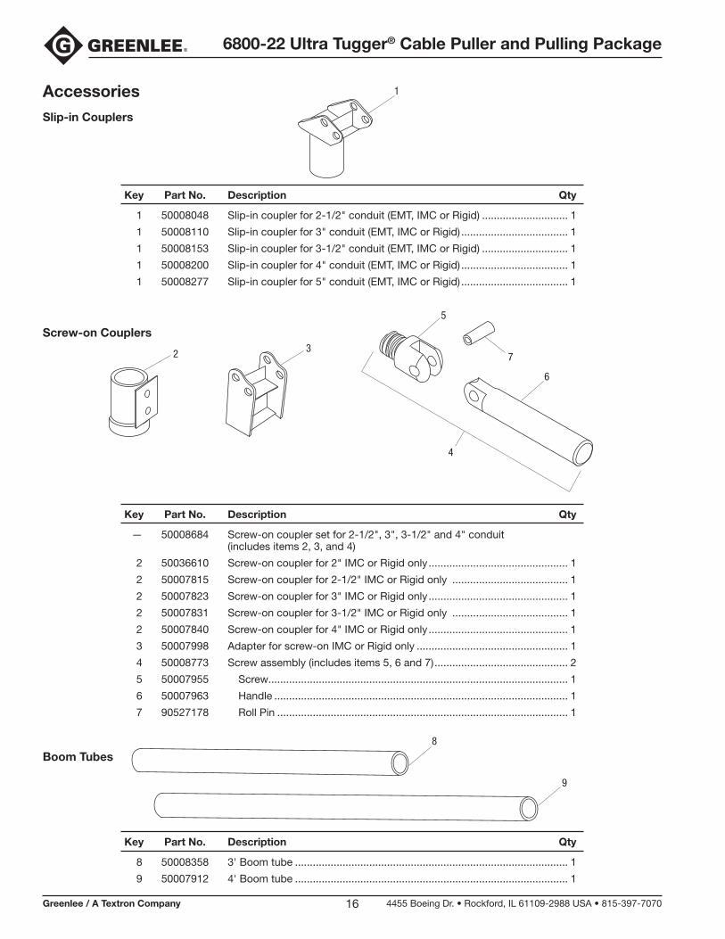
Key Part No. Description Qty
1 50008048 Slip-in coupler for 2-1/2" conduit (EMT, IMC or Rigid) ............................. 1
1 50008110 Slip-in coupler for 3" conduit (EMT, IMC or Rigid) .................................... 1
1 50008153 Slip-in coupler for 3-1/2" conduit (EMT, IMC or Rigid) ............................. 1
1 50008200 Slip-in coupler for 4" conduit (EMT, IMC or Rigid) .................................... 1
1 50008277 Slip-in coupler for 5" conduit (EMT, IMC or Rigid) .................................... 1
Key Part No. Description Qty
— 50008684 Screw-on coupler set for 2-1/2", 3", 3-1/2" and 4" conduit (includes items 2, 3, and 4)
2 50036610 Screw-on coupler for 2" IMC or Rigid only ............................................... 1
2 50007815 Screw-on coupler for 2-1/2" IMC or Rigid only ....................................... 1
2 50007823 Screw-on coupler for 3" IMC or Rigid only ............................................... 1
2 50007831 Screw-on coupler for 3-1/2" IMC or Rigid only ....................................... 1
2 50007840 Screw-on coupler for 4" IMC or Rigid only ............................................... 1
3 50007998 Adapter for screw-on IMC or Rigid only ................................................... 1
4 50008773 Screw assembly (includes items 5, 6 and 7) ............................................. 2
5 50007955 Screw..................................................................................................... 1
6 50007963 Handle ................................................................................................... 1
7 90527178 Roll Pin .................................................................................................. 1
Key Part No. Description Qty
8 50008358 3' Boom tube ............................................................................................ 1
9 50007912 4' Boom tube ............................................................................................ 1
AccessoriesSlip-in Couplers
Screw-on Couplers
Boom Tubes
1
2
5
4
7
6
3
8
9
6800-22 Ultra Tugger® Cable Puller and Pulling Package
Greenlee / A Textron Company 4455 Boeing Dr. • Rockford, IL 61109-2988 USA • 815-397-707017
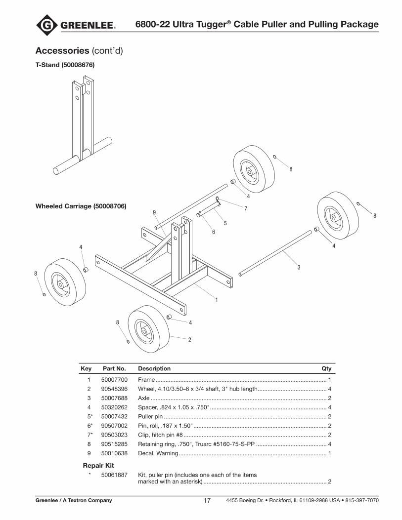
Key Part No. Description Qty
1 50007700 Frame ........................................................................................................ 1
2 90548396 Wheel, 4.10/3.50–6 x 3/4 shaft, 3" hub length .......................................... 4
3 50007688 Axle ........................................................................................................... 2
4 50320262 Spacer, .824 x 1.05 x .750" ....................................................................... 4
5* 50007432 Puller pin ................................................................................................... 2
6* 90507002 Pin, roll, .187 x 1.50" ................................................................................. 2
7* 90503023 Clip, hitch pin #8 ....................................................................................... 2
8 90515285 Retaining ring, .750", Truarc #5160-75-S-PP ........................................... 4
9 50010638 Decal, Warning .......................................................................................... 1
Repair Kit * 50061887 Kit, puller pin (includes one each of the items marked with an asterisk) ........................................................................... 2
Accessories (cont’d)T-Stand (50008676)
Wheeled Carriage (50008706)
8
4
8
4
3
1
2
8
8
4
4
9
6
5
7
6800-22 Ultra Tugger® Cable Puller and Pulling Package
Greenlee / A Textron Company 4455 Boeing Dr. • Rockford, IL 61109-2988 USA • 815-397-707018
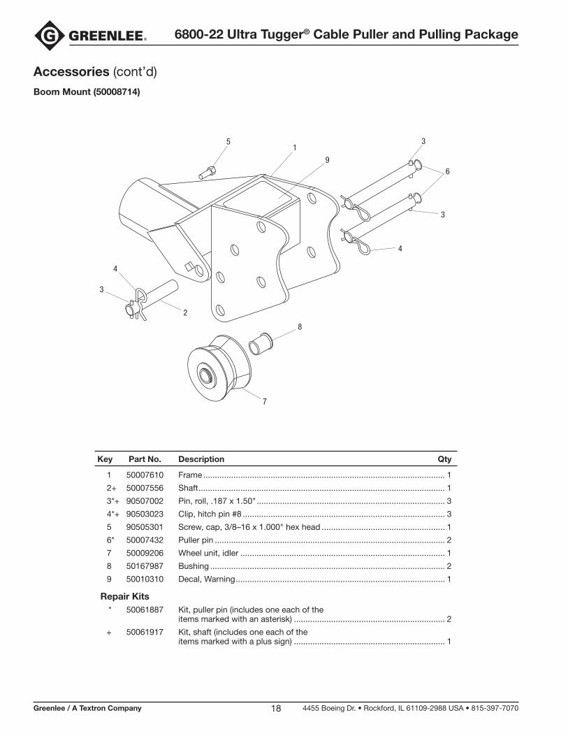
Key Part No. Description Qty
1 50007610 Frame ........................................................................................................ 1
2+ 50007556 Shaft .......................................................................................................... 1
3*+ 90507002 Pin, roll, .187 x 1.50" ................................................................................. 3
4*+ 90503023 Clip, hitch pin #8 ....................................................................................... 3
5 90505301 Screw, cap, 3/8–16 x 1.000" hex head ..................................................... 1
6* 50007432 Puller pin ................................................................................................... 2
7 50009206 Wheel unit, idler ........................................................................................ 1
8 50167987 Bushing ..................................................................................................... 2
9 50010310 Decal, Warning .......................................................................................... 1
Repair Kits * 50061887 Kit, puller pin (includes one each of the items marked with an asterisk) ................................................................. 2
+ 50061917 Kit, shaft (includes one each of the items marked with a plus sign) ................................................................. 1
Accessories (cont’d)Boom Mount (50008714)
1
96
3
3
8
7
2
4
3
4
5
6800-22 Ultra Tugger® Cable Puller and Pulling Package
Greenlee / A Textron Company 4455 Boeing Dr. • Rockford, IL 61109-2988 USA • 815-397-707019
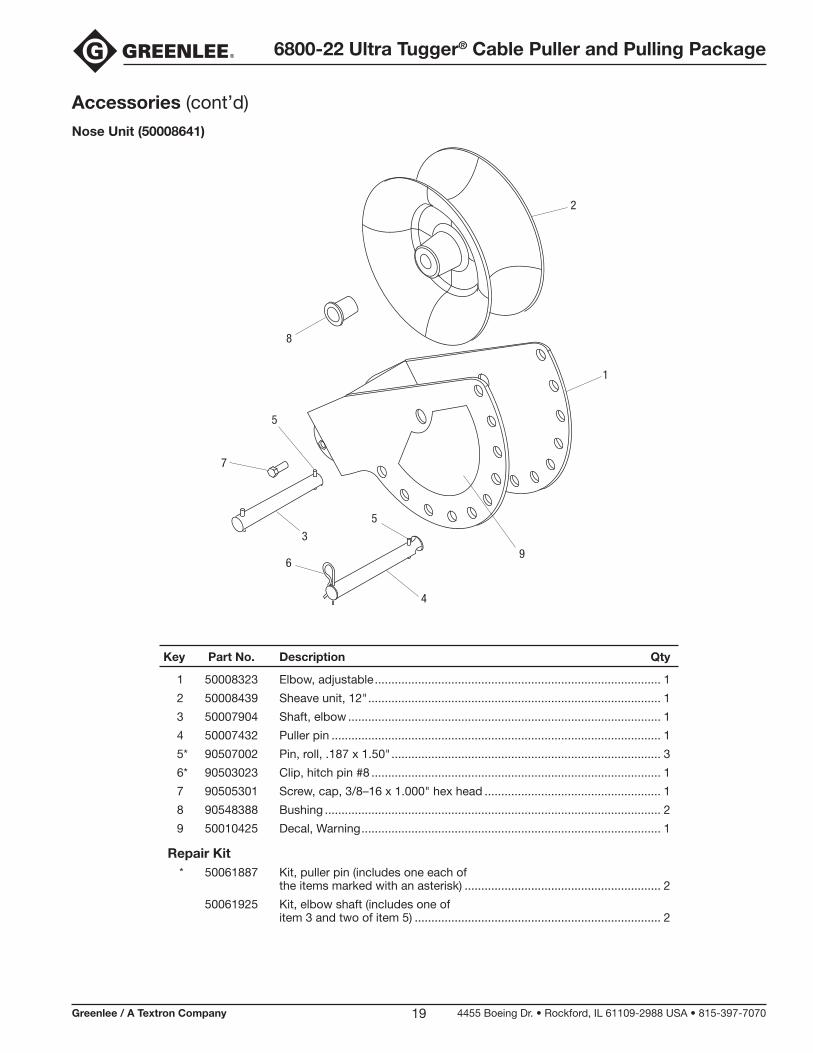
Key Part No. Description Qty
1 50008323 Elbow, adjustable ...................................................................................... 1
2 50008439 Sheave unit, 12" ........................................................................................ 1
3 50007904 Shaft, elbow .............................................................................................. 1
4 50007432 Puller pin ................................................................................................... 1
5* 90507002 Pin, roll, .187 x 1.50" ................................................................................. 3
6* 90503023 Clip, hitch pin #8 ....................................................................................... 1
7 90505301 Screw, cap, 3/8–16 x 1.000" hex head ..................................................... 1
8 90548388 Bushing ..................................................................................................... 2
9 50010425 Decal, Warning .......................................................................................... 1
Repair Kit * 50061887 Kit, puller pin (includes one each of the items marked with an asterisk) ........................................................... 2
50061925 Kit, elbow shaft (includes one of item 3 and two of item 5) .......................................................................... 2
Accessories (cont’d)Nose Unit (50008641)
8
2
1
9
4
5
6
3
5
7

6800-22 Ultra Tugger® Cable Puller and Pulling Package
Greenlee / A Textron Company 4455 Boeing Dr. • Rockford, IL 61109-2988 USA • 815-397-707020
1 50008323 Elbow, adjustable ..................................1
2 50008285 Elbow, pivot ..........................................1
3 50008439 Sheave unit, 12" ....................................1
4 50008366 Shaft, pivot ............................................1
5* 50008374 Pin, elbow .............................................1
6* 90507002 Pin, roll, .187 x 1.50" .............................3
7* 90503023 Clip, hitch pin #8 ...................................1
8 90505301 Screw, cap, 3/8–16 x 1.000" hex head ...............................................2
Key Part No. Description Qty Key Part No. Description Qty
9 90548388 Bushing .................................................2
10 50013971 Lanyard .................................................1
11 50010328 Decal, Warning ......................................1
Repair Kits * 50061941 Kit, elbow pins (includes one each of the items marked with an asterisk) .......1
50061950 Kit, pivot pins (includes one of item 4 and two of item 6) .................................1
Accessories (cont’d)Elbow Unit (50008633)
3
1
2
8
11
5
7
4
6
8
9
6
10
6800-22 Ultra Tugger® Cable Puller and Pulling Package
Greenlee / A Textron Company 4455 Boeing Dr. • Rockford, IL 61109-2988 USA • 815-397-707021
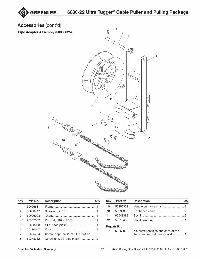
1 50006681 Frame ....................................................1
2 50008447 Sheave unit, 18" ....................................1
3* 50006908 Shaft......................................................1
4* 90507002 Pin, roll, .187 x 1.50" .............................1
5* 90503023 Clip, hitch pin #8 ...................................1
6 50296647 Foot .......................................................4
7 90505794 Screw, cap, 1/4–20 x .500", skt hd ......8
8 50278312 Screw unit, 24" vise chain ....................2
Key Part No. Description Qty Key Part No. Description Qty
9 50296302 Handle unit, vise chain ..........................2
10 50296388 Positioner, chain....................................2
11 90548388 Bushing .................................................2
12 50010468 Decal, Warning ......................................1
Repair Kit * 50061933 Kit, shaft (includes one each of the items marked with an asterisk) .............1
Accessories (cont’d)Pipe Adapter Assembly (50008625) 3
5
4
1
12
11
2
6
79
10
8
6800-22 Ultra Tugger® Cable Puller and Pulling Package
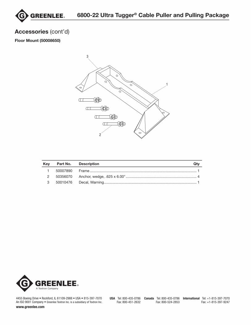
Key Part No. Description Qty
1 50007890 Frame ........................................................................................................ 1
2 50356070 Anchor, wedge, .625 x 6.00" ..................................................................... 4
3 50010476 Decal, Warning .......................................................................................... 1
Accessories (cont’d)
4455 Boeing Drive • Rockford, IL 61109-2988 • USA • 815-397-7070An ISO 9001 Company • Greenlee Textron Inc. is a subsidiary of Textron Inc.
USA Tel: 800-435-0786 Fax: 800-451-2632
Canada Tel: 800-435-0786 Fax: 800-524-2853
International Tel: +1-815-397-7070 Fax: +1-815-397-9247
www.greenlee.com
Floor Mount (50008650)
3
1
2