6877290-what-is-a-plc
TRANSCRIPT

8/8/2019 6877290-What-is-a-PLC
http://slidepdf.com/reader/full/6877290-what-is-a-plc 1/53
What is a PLC?
A PLC (i.e. Programmable Logic Controller) is a device that was invented to replace thenecessary sequential relay circuits for machine control. The PLC works by looking at its inputsand depending upon their state, turning on/off its outputs. The user enters a program, usually viasoftware, that gives the desired results. PLCs are used in many "real world" applications. If there is industry present, chances are goodthat there is a plc present. If you are involved in machining, packaging, material handling,automated assembly or countless other industries you are probably already using them. If you arenot, you are wasting money and time. Almost any application that needs some type of electricalcontrol has a need for a plc. For example, let's assume that when a switch turns on we want to turn a solenoid on for 5seconds and then turn it off regardless of how long the switch is on for. We can do this with asimple external timer. But what if the process included 10 switches and solenoids? We wouldneed 10 external timers. What if the process also needed to count how many times the switchesindividually turned on? We need a lot of external counters. As you can see the bigger the process the more of a need we have for a PLC. We can simplyprogram the PLC to count its inputs and turn the solenoids on for the specified time. This site gives you enough information to be able to write programs far more complicated thanthe simple one above. We will take a look at what is considered to be the "top 20" plc instructions.It can be safely estimated that with a firm understanding of these instructions one can solve morethan 80% of the applications in existence.That's right, more than 80%! Of course we'll learn more than just these instructions to help yousolve almost ALL your potential plc applications.
PLC HistoryIn the late 1960's PLCs were first introduced. The primary reason for designing such a device
was eliminating the large cost involved in replacing the complicated relay based machine control
8/8/2019 6877290-What-is-a-PLC
http://slidepdf.com/reader/full/6877290-what-is-a-plc 2/53
systems. Bedford Associates (Bedford, MA) proposed something called a Modular DigitalController (MODICON) to a major US car manufacturer. Other companies at the time proposedcomputer based schemes, one of which was based upon the PDP-8. The MODICON 084 broughtthe world' s first PLC into commercial production.
When production requirements changed so did the control system. This becomes very expensive
when the change is frequent. Since relays are mechanical devices they also have a limitedlifetime which required strict adhesion to maintenance schedules. Troubleshooting was also quitetedious when so many relays are involved. Now picture a machine control panel that includedmany, possibly hundreds or thousands, of individual relays. The size could be mind boggling.How about the complicated initial wiring of so many individual devices! These relays would beindividually wired together in a manner that would yield the desired outcome. Were thereproblems? You bet! These "new controllers" also had to be easily programmed by maintenance and plant engineers.The lifetime had to be long and programming changes easily performed. They also had to survivethe harsh industrial environment. That' s a lot to ask! The answers were to use a programmingtechnique most people were already familiar with and replace mechanical parts with solid-stateones.In the mid70' s the dominant PLC technologies were sequencer state-machines and the bit-slicebased CPU. The AMD 2901 and 2903 were quite popular in Modicon and A-B PLCs.Conventional microprocessors lacked the power to quickly solve PLC logic in all but the smallestPLCs. As conventional microprocessors evolved, larger and larger PLCs were being based uponthem. However, even today some are still based upon the 2903.(ref A-B' s PLC-3) Modicon hasyet to build a faster PLC than their 984A/B/X which was based upon the 2901. Communications abilities began to appear in approximately 1973. The first such system wasModicon' s Modbus. The PLC could now talk to other PLCs and they could be far away from theactual machine they were controlling. They could also now be used to send and receive varyingvoltages to allow them to enter the analog world. Unfortunately, the lack of standardizationcoupled with continually changing technology has made PLC communications a nightmare of
incompatible protocols and physical networks. Still, it was a great decade for the PLC! The 80' s saw an attempt to standardize communications with General Motor' s manufacturingautomation protocol(MAP). It was also a time for reducing the size of the PLC and making themsoftware programmable through symbolic programming on personal computers instead ofdedicated programming terminals or handheld programmers. Today the world' s smallest PLC isabout the size of a single control relay! The 90' s have seen a gradual reduction in the introduction of new protocols, and themodernization of the physical layers of some of the more popular protocols that survived the1980' s. The latest standard (IEC 1131-3) has tried to merge plc programming languages underone international standard. We now have PLCs that are programmable in function blockdiagrams, instruction lists, C and structured text all at the same time! PC' s are also being used to
replace PLCs in some applications. The original company who commissioned the MODICON 084has actually switched to a PC based control system. What will the 00' s bring? Only time will tell.

8/8/2019 6877290-What-is-a-PLC
http://slidepdf.com/reader/full/6877290-what-is-a-plc 3/53

8/8/2019 6877290-What-is-a-PLC
http://slidepdf.com/reader/full/6877290-what-is-a-plc 4/53
not worry about the others. Typically the others are checking the system and updating the currentinternal counter and timer values.
Step 1-CHECK INPUT STATUS-First the PLC takes a look at each input to determine if it is on oroff. In other words, is the sensor connected to the first input on? How about the second input?How about the third... It records this data into its memory to be used during the next step. Step 2-EXECUTE PROGRAM-Next the PLC executes your program one instruction at a time.Maybe your program said that if the first input was on then it should turn on the first output. Sinceit already knows which inputs are on/off from the previous step it will be able to decide whetherthe first output should be turned on based on the state of the first input. It will store the executionresults for use later during the next step. Step 3-UPDATE OUTPUT STATUS-Finally the PLC updates the status of the outputs. It updatesthe outputs based on which inputs were on during the first step and the results of executing yourprogram during the second step. Based on the example in step 2 it would now turn on the firstoutput because the first input was on and your program said to turn on the first output when thiscondition is true. After the third step the PLC goes back to step one and repeats the steps continuously. One scantime is defined as the time it takes to execute the 3 steps listed above.
Response TimeThe total response time of the PLC is a fact we have to consider when shopping for a PLC. Just
like our brains, the PLC takes a certain amount of time to react to changes. In many applicationsspeed is not a concern, in others though... If you take a moment to look away from this text you might see a picture on the wall. Your eyes
actually see the picture before your brain says "Oh, there' s a picture onthe wall". In this exampleyour eyes can be considered the sensor. The eyes are connected to the input circuit of yourbrain. The input circuit of your brain takes a certain amount of time to realize that your eyes sawsomething. (If you have been drinking alcohol this input response time would be longer! )Eventually your brain realizes that the eyes have seen something and it processes the data. Itthen sends an output signal to your mouth. Your mouth receives this data and begins to respondto it. Eventually your mouth utters the words "Gee, that' s a really ugly picture!".

8/8/2019 6877290-What-is-a-PLC
http://slidepdf.com/reader/full/6877290-what-is-a-plc 5/53
Notice in this example we had to respond to 3 things: INPUT- It took a certain amount of time for the brain to notice the inputsignal from the eyes. EXECUTION- It took a certain amount of time to process theinformation received from the eyes. Consider the program to be: If theeyes see an ugly picture then output appropriate words to the mouth. OUTPUT- The mouth receives a signal from the brain and eventuallyspits (no pun intended) out the words "Gee, that' s a really ugly picture!
Response Time Concerns
Now that we know about response time, here' s what it really means to
the application. The PLC can only see an input turn on/off when it' slooking. In other words, it only looks at its inputs during the check inputstatus part of the scan.
In the diagram, input 1 is not seen until scan 2. This is because when input 1 turned on, scan 1had already finished looking at the inputs.
Input 2 is not seen until scan 3. This is also because when the input turned on scan 2 had alreadyfinished looking at the inputs.Input 3 is never seen. This is because when scan 3 was looking at the inputs, signal 3 was not onyet. It turns off before scan 4 looks at the inputs. Therefore signal 3 is never seen by the plc.

8/8/2019 6877290-What-is-a-PLC
http://slidepdf.com/reader/full/6877290-what-is-a-plc 6/53
To avoid this we say that the input should be onfor at least 1 input delay time + one scan time.
But what if it was not possible for the input to be on this long? Then the plc doesn' t see the inputturn on. Therefore it becomes a paper weight! Not true... of course there must be a way to getaround this. Actually there are 2 ways.
Pulse stretch function. This function extends the lengthof the input signal until the plc looks at the inputs duringthe next scan.( i.e. it stretches the duration of the pulse.)
Interrupt function. This function interrupts the scan toprocess a special routine that you have written. i.e. Assoon as the input turns on, regardless of where the scancurrently is, the plc immediately stops what its doing andexecutes an interrupt routine. (A routine can be thoughtof as a mini program outside of the main program.) Afterits done executing the interrupt routine, it goes back tothe point it left off at and continues on with the normalscan process.
Now let' s consider the longest time for an output to actually turn on. Let' s assume that when aswitch turns on we need to turn on a load connected to the plc output.The diagram below shows the longest delay (worst case because the input is not seen until scan2) for the output to turn on after the input has turned on.The maximum delay is thus 2 scan cycles - 1 input delay time.
It's not so difficult, now is it ?

8/8/2019 6877290-What-is-a-PLC
http://slidepdf.com/reader/full/6877290-what-is-a-plc 7/53
RelaysNow that we understand how the PLC processes inputs, outputs, and the actual program we are
almost ready to start writing a program. But first lets see how a relay actually works. After all, the
main purpose of a plc is to replace "real-world" relays. We can think of a relay as an electromagnetic switch. Apply a voltage to the coil and a magneticfield is generated. This magnetic field sucks the contacts of the relay in, causing them to make aconnection. These contacts can be considered to be a switch. They allow current to flow between2 points thereby closing the circuit. Let' s considerthe following example. Here we simply turn on a bell (Lunch time!) whenever aswitch is closed. We have 3 real-world parts. A switch, a relay and a bell. Whenever the switchcloses we apply a current to a bell causing it to sound.
Notice in the picture that we have 2 separate circuits. The bottom(blue) indicates the DC part.The top(red) indicates the AC part. Here we are using a dc relay to control an AC circuit. That' s the fun of relays! When the switch isopen no current can flow through the coil of the relay. As soon as the switch is closed, however,current runs through the coil causing a magnetic field to build up. This magnetic field causes thecontacts of the relay to close. Now AC current flows through the bell and we hear it. Lunch time!
A typical industrial relayReplacing Relays
Next, lets use a plc in place of the relay. (Note that this might not be very cost effective for this
application but it does demonstrate the basics we need.) The first thing that' s necessary is tocreate what' s called a ladder diagram. After seeing a few of these it will become obvious why its

8/8/2019 6877290-What-is-a-PLC
http://slidepdf.com/reader/full/6877290-what-is-a-plc 8/53
called a ladder diagram. We have to create one of these because, unfortunately, a plc doesn' tunderstand a schematic diagram. It only recognizes code. Fortunately most PLCs have softwarewhich convert ladder diagrams into code. This shields us from actually learning the plc' s code.
First step- We have to translate all of the items we' re using into symbols the plc understands.The plc doesn' t understand terms like switch, relay, bell, etc. It prefers input, output, coil, contact,
etc. It doesn' t care what the actual input or output device actually is. It only cares that its an inputor an output. First we replace the battery with a symbol. This symbol is common to all ladder diagrams. Wedraw what are called bus bars. These simply look like two vertical bars. One on each side of thediagram. Think of the left one as being + voltage and the right one as being ground. Further thinkof the current (logic) flow as being from left to right.Next we give the inputs a symbol. In this basic example we have one real world input. (i.e. theswitch) We give the input that the switch will be connected to, to the symbol shown below. Thissymbol can also be used as the contact of a relay.
A contact symbolNext we give the outputs a symbol. In this example we use one output (i.e. the bell). We give theoutput that the bell will be physically connected to the symbol shown below. This symbol is usedas the coil of a relay.
A coil symbolThe AC supply is an external supply so we don' t put it in our ladder. The plc only cares aboutwhich output it turns on and not what' s physically connected to it.
Second step- We must tell the plc where everything is located. In other words we have to give allthe devices an address. Where is the switch going to be physically connected to the plc? Howabout the bell? We start with a blank road map in the PLCs town and give each item an address.Could you find your friends if you didn' t know their address? You know they live in the same townbut which house? The plc town has a lot of houses (inputs and outputs) but we have to figure outwho lives where (what device is connected where). We' ll get further into the addressing schemelater. The plc manufacturers each do it a different way! For now let' s say that our input will becalled "0000". The output will be called "500".Final step- We have to convert the schematic into a logical sequence of events. This is mucheasier than it sounds. The program we' re going to write tells the plc what to do when certainevents take place. In our example we have to tell the plc what to do when the operator turns onthe switch. Obviously we want the bell to sound but the plc doesn' t know that. It' s a pretty stupid
device, isn' t it!

8/8/2019 6877290-What-is-a-PLC
http://slidepdf.com/reader/full/6877290-what-is-a-plc 9/53
The picture above is the final converted diagram. Notice that we eliminated the real world relayfrom needing a symbol. It' s actually "inferred" from the diagram.Huh? Don' t worry, you' ll see whatwe mean as we do more examples.
Basic InstructionsNow let' s examine some of the basic instructions is greater detail to see more
about what each one does. Load
The load (LD) instruction is a normally open contact. It is sometimes also called examine ifon.(XIO) (as in examine the input to see if its physically on) The symbol for a load instruction isshown below.
A LoaD (contact) symbolThis is used when an input signal is needed to be present for the symbol to turn on. When thephysical input is on we can say that the instruction is True. We examine the input for an on signal.If the input is physically on then the symbol is on. An on condition is also referred to as a logic 1state. This symbol normally can be used for internal inputs, external inputs and external outputcontacts. Remember that internal relays don' t physically exist. They are simulated (software)relays.
LoadBar The LoaDBar instruction is a normally closed contact. It is sometimes also called LoaDNot orexamine if closed. (XIC) (as in examine the input to see if its physically closed) The symbol for aloadbar instruction is shown below.
A LoaDNot (normally closed contact) symbolThis is used when an input signal does not need to be present for the symbol to turn on. Whenthe physical input is off we can say that the instruction is True. We examine the input for an offsignal. If the input is physically off then the symbol is on. An off condition is also referred to as alogic 0 state. This symbol normally can be used for internal inputs, external inputs and sometimes, externaloutput contacts. Remember again that internal relays don' t physically exist. They are simulated(software) relays. It is the exact opposite of the Load instruction. *NOTE- With most PLCs this instruction (Load or Loadbar) MUST be the first symbol on the left ofthe ladder.
Logic State Load LoadBar
8/8/2019 6877290-What-is-a-PLC
http://slidepdf.com/reader/full/6877290-what-is-a-plc 10/53
0 False True 1 True False
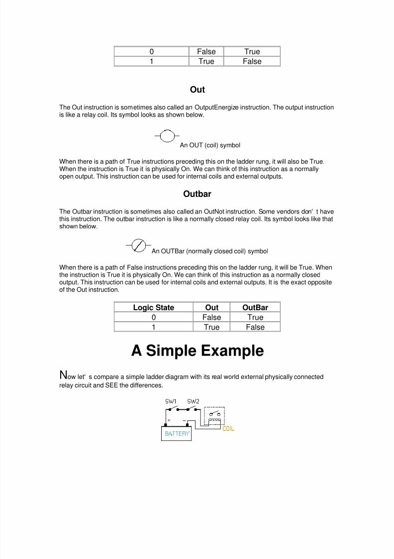
Out The Out instruction is sometimes also called an OutputEnergize instruction. The output instructionis like a relay coil. Its symbol looks as shown below.
An OUT (coil) symbolWhen there is a path of True instructions preceding this on the ladder rung, it will also be True.When the instruction is True it is physically On. We can think of this instruction as a normallyopen output. This instruction can be used for internal coils and external outputs.
Outbar The Outbar instruction is sometimes also called an OutNot instruction. Some vendors don' t havethis instruction. The outbar instruction is like a normally closed relay coil. Its symbol looks like thatshown below.
An OUTBar (normally closed coil) symbolWhen there is a path of False instructions preceding this on the ladder rung, it will be True. Whenthe instruction is True it is physically On. We can think of this instruction as a normally closedoutput. This instruction can be used for internal coils and external outputs. It is the exact oppositeof the Out instruction.
Logic State Out OutBar 0 False True 1 True False
A Simple ExampleNow let' s compare a simple ladder diagram with its real world external physically connected
relay circuit and SEE the differences.

8/8/2019 6877290-What-is-a-PLC
http://slidepdf.com/reader/full/6877290-what-is-a-plc 11/53
In the above circuit, the coil will be energized when there is a closed loop between the + and -terminals of the battery. We can simulate this same circuit with a ladder diagram. A ladderdiagram consists of individual rungs just like on a real ladder. Each rung must contain one ormore inputs and one or more outputs. The first instruction on a rung must always be an inputinstruction and the last instruction on a rung should always be an output (or its equivalent).
Notice in this simple one rung ladder diagram we have recreated the external circuit above with aladder diagram. Here we used the Load and Out instructions. Some manufacturers require thatevery ladder diagram include an END instruction on the last rung. Some PLCs also require anENDH instruction on the rung after the END rung. Next we' ll trace the registers. Registers? Let' s see...
PLC RegistersWe' ll now take the previous example and change switch 2 (SW2) to a normally closed symbol
(loadbar instruction). SW1 will be physically OFF and SW2 will be physically ON initially. Theladder diagram now looks like this:
Notice also that we now gave each symbol (or instruction) an address. This address sets aside acertain storage area in the PLCs data files so that the status of the instruction (i.e. true/false) canbe stored. Many PLCs use 16 slot or bit storage locations. In the example above we are usingtwo different storage locations or registers.
REGISTER 0015 14 13 12 11 10 09 08 07 06 05 04 03 02 01 00 1 0
REGISTER 0515 14 13 12 11 10 09 08 07 06 05 04 03 02 01 00 0

8/8/2019 6877290-What-is-a-PLC
http://slidepdf.com/reader/full/6877290-what-is-a-plc 12/53
In the tables above we can see that in register 00, bit 00 (i.e. input 0000) was a logic 0 and bit 01(i.e. input 0001) was a logic 1. Register 05 shows that bit 00 (i.e. output 0500) was a logic 0. Thelogic 0 or 1 indicates whether an instruction is False or True. *Although most of the items in the register tables above are empty, they should each contain a 0. They were left blank to emphasize the locations we were concerned with.
LOGICAL CONDITION OF SYMBOLLOGIC BITS LD LDB OUTLogic 0 False True FalseLogic 1 True False True
The plc will only energize an output when all conditions on the rung are TRUE. So, looking at thetable above, we see that in the previous example SW1 has to be logic 1 and SW2 must be logic0. Then and ONLY then will the coil be true (i.e. energized). If any of the instructions on the rungbefore the output (coil) are false then the output (coil) will be false (not energized). Let' s now look at a truth table of our previous program to further illustrate this important point. Ourtruth table will show ALL possible combinations of the status of the two inputs.
Inputs Outputs Register Logic BitsSW1(LD) SW2(LDB) COIL(OUT) SW1(LD) SW2(LDB) COIL(OUT)
False True False 0 0 0False False False 0 1 0True True True 1 0 1True False False 1 1 0
Notice from the chart that as the inputs change their states over time, so will the output. Theoutput is only true (energized) when all preceding instructions on the rung are true.
A Level ApplicationNow that we' ve seen how registers work, let' s process a program like PLCs do to enhance our
understanding of how the program gets scanned .Let' s consider the following application:We are controlling lubricating oil being dispensed from a tank. This is possible by using twosensors. We put one near the bottom and one near the top, as shown in the picture below.

8/8/2019 6877290-What-is-a-PLC
http://slidepdf.com/reader/full/6877290-what-is-a-plc 13/53
Here, we want the fill motor to pump lubricating oil into the tank until the high level sensor turnson. At that point we want to turn off the motor until the level falls below the low level sensor. Thenwe should turn on the fill motor and repeat the process.Here we have a need for 3 I/O (i.e. Inputs/Outputs). 2 are inputs (the sensors) and 1 is an output(the fill motor). Both of our inputs will be NC (normally closed) fiber-optic level sensors. Whenthey are NOT immersed in liquid they will be ON. When they are immersed in liquid they will beOFF. We will give each input and output device an address. This lets the plc know where they arephysically connected. The addresses are shown in the following tables:
Inputs Address Output Address Internal Utility RelayLow 0000 Motor 0500 1000High 0001
Below is what the ladder diagram will actually look like. Notice that we are using an internal utility
relay in this example. You can use the contacts of these relays as many times as required. Herethey are used twice to simulate a relay with 2 sets of contacts. Remember, these relays DO NOTphysically exist in the plc but rather they are bits in a register that you can use to SIMULATE arelay.
We should always remember that the most common reason for using PLCs in our applications isfor replacing real-world relays. The internal utility relays make this action possible. It' s impossibleto indicate how many internal relays are included with each brand of plc. Some include 100' swhile other include 1000' s while still others include 10' s of 1000' s! Typically, plc size (not physicalsize but rather I/O size) is the deciding factor. If we are using a micro-plc with a few I/O we don' t

8/8/2019 6877290-What-is-a-PLC
http://slidepdf.com/reader/full/6877290-what-is-a-plc 14/53
need many internal relays. If however, we are using a large plc with 100' s or 1000' s of I/O we' llcertainly need many more internal relays.If ever there is a question as to whether or not the manufacturer supplies enough internal relays,consult their specification sheets. In all but the largest of large applications, the supplied amountshould be MORE than enough.
The Program ScanLet' s watch what happens in this programscan by scan.
Initially the tank is empty. Therefore, input 0000 is TRUE and input 0001 is also TRUE.
Scan 1
Scan 2-100Gradually the tank fills because 500(fill motor) is on. After 100 scans the oil level rises above the low level sensor and it becomes open. (i.e. FALSE)

8/8/2019 6877290-What-is-a-PLC
http://slidepdf.com/reader/full/6877290-what-is-a-plc 15/53
Scan 101-1000
Notice that even when the low level sensor is false there is still a path of true logic from left toright. This is why we used an internal relay. Relay 1000 is latching the output (500) on. It will staythis way until there is no true logic path from left to right.(i.e. when 0001 becomes false)After 1000 scans the oil level rises above the high level sensor at it also becomes open (i.e. false)
Scan 1001
Scan 1002Since there is no more true logic path, output 500 is no longer energized (true) and therefore themotor turns off.After 1050 scans the oil level falls below the high level sensor and it will become true again.
Scan 1050
Notice that even though the high level sensor became true there still is NO continuous true logicpath and therefore coil 1000 remains false!

8/8/2019 6877290-What-is-a-PLC
http://slidepdf.com/reader/full/6877290-what-is-a-plc 16/53
After 2000 scans the oil level falls below the low level sensor and it will also become true again.At this point the logic will appear the same as SCAN 1 above and the logic will repeat asillustrated above.
Latch InstructionsNow that we understand how inputs and outputs are processed by the plc, let' s look at a
variation of our regular outputs. Regular output coils are of course an essential part of ourprograms but we must remember that they are only TRUE when ALL INSTRUCTIONS beforethem on the rung are also TRUE. What happens if they are not? Then of course, the output willbecome false.(turn off) Think back to the lunch bell example we did a few chapters ago. What would' ve happened if wecouldn' t find a "push on/push off" switch? Then we would' ve had to keep pressing the button foras long as we wanted the bell to sound. (A momentary switch) The latching instructions let us usemomentary switches and program the plc so that when we push one the output turns on andwhen we push another the output turns off.Maybe now you' re saying to yourself "What the heck is he talking about?". (It' s also what I' mthinking!) So let' s do a real world example.Picture the remote control for your TV. It has a button for ON and another for OFF. (mine does,anyway) When I push the ON button the TV turns on. When I push the OFF button the TV turnsoff. I don' t have to keep pushing the ON button to keep theTV on. This would be the function of alatching instruction. The latch instruction is often called a SET or OTL (output latch). The unlatch instruction is oftencalled a RES (reset), OUT (output unlatch) or RST (reset). The diagram below shows how to usethem in a program.
Here we are using 2 momentary push button switches. One is physically connected to input 0000while the other is physically connected to input 0001. When the operator pushes switch 0000 theinstruction "set 0500" will become true and output 0500 physically turns on. Even after theoperator stops pushing the switch, the output (0500) will remain on. It is latched on. The only way
to turn off output 0500 is turn on input 0001. This will cause the instruction "res 0500" to becometrue thereby unlatching or resetting output 0500.
Click here and view the animation to really learn!Here' s something to think about. What would happen if input 0000 and 0001 both turn on at theexact same time.

8/8/2019 6877290-What-is-a-PLC
http://slidepdf.com/reader/full/6877290-what-is-a-plc 17/53
Will output 0500 be latched or unlatched? To answer this question we have to think about the scanning sequence. The ladder is alwaysscanned from top to bottom, left to right. The first thing in the scan is to physically look at theinputs. 0000 and 0001 are both physically on. Next the plc executes the program. Starting fromthe top left, input 0000 is true therefore it should set 0500. Next it goes to the next rung and since
input 0001 is true it should reset 0500. The last thing it said was to reset 0500. Therefore on thelast part of the scan when it updates the outputs it will keep 0500 off. (i.e. reset 0500). Makes better sense now, doesn't it?
CountersA counter is a simple device intended to do one simple thing - count. Using them, however, can
sometimes be a challenge because every manufacturer (for whatever reason) seems to use thema different way. Rest assured that the following information will let you simply and easily programanybody' s counters.
What kinds of counters are there? Well, there are up-counters (they only count up 1,2,3...).These are called CTU,(count up) CNT,C, or CTR. There are down counters (they only countdown 9,8,7,...). These are typically called CTD (count down) when they are a separate instruction.There are also up-down counters (they count up and/or down 1,2,3,4,3,2,3,4,5,...) These aretypically called UDC(up-down counter) when they are separate instructions. Many manufacturers have only one or two types of counters but they can be used to count up,down or both. Confused yet? Can you say "no standardization"? Don' t worry, the theory is all thesame regardless of what the manufacturers call them. A counter is a counter is a counter... To further confuse the issue, most manufacturers also include a limited number of high-speed
counters. These are commonly called HSC (high-speed counter), CTH (CounTer High-speed?) orwhatever.Typically a high-speed counter is a "hardware " device. The normal counters listed above aretypically "software " counters. In other words they don' t physically exist in the plc but rather theyare simulated in software. Hardware counters do exist in the plc and they are not dependent onscan time.A good rule of thumb is simply to always use the normal (software) counters unless the pulsesyou are counting will arrive faster than 2X the scan time. (i.e. if the scan time is 2ms and pulseswill be arriving for counting every 4ms or longer then use a software counter. If they arrive fasterthan every 4ms (3ms for example) then use the hardware (high-speed) counters. (2xscan time =2x2ms= 4ms) To use them we must know 3 things:
1. Where the pulses that we want to count are coming from. Typically this is from one of theinputs.(a sensor connected to input 0000 for example)
2. How many pulses we want to count before we react. Let' s count 5 widgets before we boxthem, for example.
3. When/how we will reset the counter so it can count again. After we count 5 widgets letsreset the counter, for example.

8/8/2019 6877290-What-is-a-PLC
http://slidepdf.com/reader/full/6877290-what-is-a-plc 18/53
When the program is running on the plc the program typically displays the current or"accumulated " value for us so we can see the current count value. Typically counters can count from 0 to 9999, -32,768 to +32,767 or 0 to 65535. Why the weirdnumbers? Because most PLCs have 16-bit counters. We' ll get into what this means in a laterchapter but for now suffice it to say that 0-9999 is 16-bit BCD (binary coded decimal) and that -32,768 to 32767 and 0 to 65535 is 16-bit binary. Here are some of the instruction symbols we will encounter (depending on which manufacturerwe choose) and how to use them. Remember that while they may look different they are all usedbasically the same way. If we can setup one we can setup any of them.
In this counter we need 2 inputs.One goes before the reset line. When this input turns on the current (accumulated) count valuewill return to zero.The second input is the address where the pulses we are counting are coming from. For example, if we are counting how many widgets pass in front of the sensor that is physically
connected to input 0001 then we would put normally open contacts with the address 0001 in frontof the pulse line. Cxxx is the name of the counter. If we want to call it counter 000 then we would put "C000" here. yyyyy is the number of pulses we want to count before doing something. If we want to count 5widgets before turning on a physical output to box them we would put 5 here. If we wanted tocount 100 widgets then we would put 100 here, etc. When the counter is finished (i.e we countedyyyyy widgets) it will turn on a separate set of contacts that we also label Cxxx. Note that the counter accumulated value ONLY changes at the off to on transition of the pulseinput.
Here' s the symbol on a ladder showing how we set up a counter (we' ll name it counter 000) tocount 100 widgets from input 0001 before turning on output 500. Sensor 0002 resets the counter. Below is one symbol we may encounter for an up-down counter. We' ll use the same abbreviationas we did for the example above.(i.e. UDCxxx and yyyyy)
In this up-down counter we need to assign 3 inputs. The reset input has the same function asabove. However, instead of having only one input for the pulse counting we now have 2. One isfor counting up and the other is for counting down. In this example we will call the counterUDC000 and we will give it a preset value of 1000. (we' ll count 1000 total pulses) For inputs we' ll

8/8/2019 6877290-What-is-a-PLC
http://slidepdf.com/reader/full/6877290-what-is-a-plc 19/53
use a sensor which will turn on input 0001 when it sees a target and another sensor at input 0003will also turn on when it sees a target. When input 0001 turns on we count up and when input0003 turns on we count down. When we reach 1000 pulses we will turn on output 500. Again notethat the counter accumulated value ONLY changes at the off to on transition of the pulse input.The ladder diagram is shown below.
Click here and view the animation to really learn!
One important thing to note is that counters and timers can' t have the same name (in mostPLCs). This is because they typically use the same registers. We haven' t learned about timersyet but you might make a note of this for future reference because it' s pretty important.Well, the counters above might seem difficult to understand but they' re actually quite easy oncewe get used to using them. They certainly are an essential tool. They are also one of the least"standardized " basic instructions that we will see. However, always remember that the theory isthe same from manufacturer to manufacturer!
Timers
Let' s now see how a timer works. What is a timer? Its exactly what the word says... it is an
instruction that waits a set amount of time before doing something. Sounds simple doesn' t it.
When we look at the different kinds of timers available the fun begins. As always, different typesof timers are available with different manufacturers. Here are most of them:
• On-Delay timer-This type of timer simply "delays turning on". In other words, after oursensor (input) turns on we wait x-seconds before activating a solenoid valve (output).This is the most common timer. It is often called TON (timer on-delay), TIM (timer) orTMR (timer).
• Off-Delay timer- This type of timer is the opposite of the on-delay timer listed above.This timer simply "delays turning off". After our sensor (input) sees a target we turn on a
solenoid (output). When the sensor no longer sees the target we hold the solenoid on forx-seconds before turning it off. It is called a TOF (timer off-delay) and is less commonthan the on-delay type listed above. (i.e. few manufacturers include this type of timer)
• Retentive or Accumulating timer- This type of timer needs 2 inputs. One input startsthe timing event (i.e. the clock starts ticking) and the other resets it. The on/off delaytimers above would be reset if the input sensor wasn' t on/off for the complete timerduration. This timer however holds or retains the current elapsed time when the sensorturns off in mid-stream. For example, we want to know how long a sensor is on for duringa 1 hour period. If we use one of the above timers they will keep resetting when the

8/8/2019 6877290-What-is-a-PLC
http://slidepdf.com/reader/full/6877290-what-is-a-plc 20/53
sensor turns off/on. This timer however, will give us a total or accumulated time. It is oftencalled an RTO (retentive timer) or TMRA (accumulating timer).
Let' s now see how to use them. We typically need toknow 2 things:1. What will enable the timer. Typically this is one of the inputs.(a sensor connected to
input 0000 for example)2. How long we want to delay before we react. Let' s wait 5 seconds before we turn on a
solenoid, for example.
When the instructions before the timer symbol are true the timer starts "ticking". When the timeelapses the timer will automatically close its contacts. When the program is running on the plc theprogram typically displays the elapsed or "accumulated " time for us so we can see the currentvalue. Typically timers can tick from 0 to 9999 or 0 to 65535 times. Why the weird numbers? Again its because most PLCs have 16-bit timers. We' ll get into what thismeans in a later chapter but for now suffice it to say that 0-9999 is 16-bit BCD (binary codeddecimal) and that 0 to 65535 is 16-bit binary. Each tick of the clock is equal to x-seconds. Typically each manufacturer offers several different ticks. Most manufacturers offer 10 and 100ms increments (ticks of the clock). An "ms" is a milli-second or 1/1000th of a second. Several
manufacturers also offer 1ms as well as 1 second increments. These different increment timerswork the same as above but sometimes they have different names to show their timebase. Someare TMH (high speed timer), TMS (super high speed timer) or TMRAF (accumulating fast timer) Shown below is a typical timer instruction symbol we will encounter (depending on whichmanufacturer we choose) and how to use it. Remember that while they may look different theyare all used basically the same way. If we can setup one we can setup any of them.
This timer is the on-delay type and is named Txxx. When the enable input is on the timer starts totick. When it ticks yyyyy (the preset value) times, it will turn on its contacts that we will use later in
the program. Remember that the duration of a tick (increment) varies with the vendor and thetimebase used. (i.e. a tick might be 1ms or 1 second or...)
Below is the symbol shown on a ladder diagram: In this diagram we wait for input 0001 to turn on. When it does, timer T000 (a 100ms increment
timer) starts ticking. It will tick 100 times. Each tick (increment) is 100ms so the timer will be a10000ms (i.e. 10 second) timer. 100ticks X 100ms = 10,000ms. When 10 seconds have elapsed,the T000 contacts close and 500 turns on. When input 0001 turns off(false) the timer T000 willreset back to 0 causing its contacts to turn off(become false) thereby making output 500 turn backoff.
Click here and view the animation to really learn!

8/8/2019 6877290-What-is-a-PLC
http://slidepdf.com/reader/full/6877290-what-is-a-plc 21/53
An accumulating timer would look similar to this:
This timer is named Txxx. When the enable input is on the timer starts to tick. When it ticks yyyyy(the preset value) times, it will turn on its contacts that we will use later in the program.Remember that the duration of a tick (increment) varies with the vendor and the timebase used.(i.e. a tick might be 1ms or 1 second or...) If however, the enable input turns off before the timerhas completed, the current value will be retained. When the input turns back on, the timer willcontinue from where it left off. The only way to force the timer back to its preset value to startagain is to turn on the reset input.
The symbol is shown in the ladder diagram below. In this diagram we wait for input 0002 to turn on. When it does timer T000 (a 10ms incrementtimer) starts ticking. It will tick 100 times. Each tick (increment) is 10ms so the timer will be a1000ms (i.e. 1 second) timer. 100ticks X 10ms = 1,000ms. When 1 second has elapsed, theT000 contacts close and 500 turns on. If input 0002 turns back off the current elapsed time will beretained. When 0002 turns back on the timer will continue where it left off. When input 0001 turnson (true) the timer T000 will reset back to 0 causing its contacts to turn off (become false) therebymaking output 500 turn back off.
Click here and view the animation to really learn!One important thing to note is that counters and timers can't have the same name (in mostPLCs). This is because they typically use the same registers. Always remember that although the symbols may look different they all operate the same way.Typically the major differences are in the duration of the ticks increments.
Timer AccuracyNow that we' ve seen how timers are created and used, let' s learn a little about their precision.
When we are creating a timer that lasts a few seconds, or more, we can typically not be veryconcerned about their precision because it' s usually insignificant. However, when we' re creating
timers that have a duration in the millisecond (1ms= 1/1000 second) range we MUST beconcerned about their precision. There are general two types of errors when using a timer. The first is called an input error. Theother is called an output error. The total error is the sum of both the input and output errors.
• Input error- An error occurs depending upon when the timer input turns on during thescan cycle. When the input turns on immediately after the plc looks at the status of theinputs during the scan cycle, the input error will be at its largest. (i.e. more than 1 full

8/8/2019 6877290-What-is-a-PLC
http://slidepdf.com/reader/full/6877290-what-is-a-plc 22/53
scan time!). This is because, as you will recall, (see scan time chapter) the inputs arelooked at once during a scan. If it wasn' t on when the plc looked and turns on later in thescan we obviously have an error. Further we have to wait until the timer instruction isexecuted during the program execution part of the scan. If the timer instruction is the lastinstruction on the rung it could be quite a big error!
• Output error- An another error occurs depending upon when in the ladder the timer
actually "times out" (expires) and when the plc finishes executing the program to get tothe part of the scan when it updates the outputs. (again, see scan time chapter) This isbecause the timer finishes during the program execution but the plc must first finishexecuting the remainder of the program before it can turn on the appropriate output.
Below is a diagram illustrating the worst possible input error. You will note from it that the worstpossible input error would be 1 complete scan time + 1 program execution time. Rememberthat a program execution time varies from program to program. (depends how many instructionsare in the program!)
Shown below is a diagram illustrating the worst possible output error. You can see from it that theworst possible output error would be 1 complete scan time.
Based upon the above information we can now see that the total worst possible timer error wouldbe equal to:1 scan time + 1 program execution time + 1 scan time= 2 scan times + 1 program execution time. What does this really mean ? It means that even though most manufacturers currently have timerswith 1ms increments they really shouldn' t be used for durations less than a few milliseconds. Thisassumes that your scan time is 1ms. If your scan time is 5ms you had better not use a timer witha duration less than about 15ms. The point is however, just so that we will know what errors wecan expect. If we know what error to expect, we can then think about whether this amount of erroris acceptable for our application. In most applications this error is insignificant but in some highspeed or very precise applications this error can be VERY significant.We should also note that the above errors are only the "software errors ". There is also ahardware input error as well as a hardware output error. The hardware input error is caused by the time it takes for the plc to actually realize that the input
is on when it scans its inputs. Typically this duration is about 10ms. This is because many PLCsrequire that an input should be physically on for a few scans before it determines its physically on.(to eliminate noise or "bouncing" inputs) The hardware output error is caused by the time it takes from when the plc tells its output tophysically turn on until the moment it actually does. Typically a transistor takes about 0.5mswhereas a mechanical relay takes about 10ms. The error keeps on growing doesn' t it! If it becomes too big for the application, consider using anexternal "hardware" timer.

8/8/2019 6877290-What-is-a-PLC
http://slidepdf.com/reader/full/6877290-what-is-a-plc 23/53
One-shotsA one-shot is an interesting and invaluable programming tool. At first glance it might be difficult
to figure out why such an instruction is needed. After we understand what this instruction does
and how to use it, however, the necessity will become clear. A one-shot is used to make something happen for ONLY 1 SCAN. (you do remember what ascan is, right??) Most manufacturers have one-shots that react to an off to on transition and adifferent type that reacts to an on to off transition. Some names for the instructions could bedifu/difd (differentiate up/down), sotu/sotd (single output up/down), osr (one-shot rising) andothers. They all, however, end up with the same result regardless of the name.
One-shot InstructionAbove is the symbol for a difu (one-shot) instruction. A difd looks the same but inside the symbol
it says "difd". Some of the manufacturers have it in the shape of a box but, regardless of thesymbol, they all function the same way. For those manufacturers that don' t include a differentiatedown instruction, you can get the same effect by putting a NC (normally closed) instruction beforeit instead of a NO(normally open) instruction. (i.e. reverse the logic before the difu instruction)Let' s now setup an application to see how this instruction actually functions in a ladder. Thisinstruction is most often used with some of the advanced instructions where we do some thingsthat MUST happen only once. However, since we haven' t gotten that far yet, let' s set up a flip/flopcircuit. In simple terms, a flip/flop turns something around each time an action happens. Herewe' ll use a single pushbutton switch. The first time the operator pushes it we want an output toturn on. It will remain "latched" on until the next time the operator pushes the button. When hedoes, the output turns off.
Here' s the ladder diagram that does just that: Now this looks confusing! Actually it' s not if we take it one step at a time.
• Rung 1-When NO (normally open) input 0000 becomes true DIFU 1000 becomes true.
• Rung 2- NO 1000 is true, NO 1001 remains false, NC 1001 remains true, NC 1000 turnsfalse. Since we have a true path, (NO 1000 & NC 1001) OUT 1001 becomes true.
• Rung 3- NO 1001 is true therefore OUT 500 turns true.
Next Scan

8/8/2019 6877290-What-is-a-PLC
http://slidepdf.com/reader/full/6877290-what-is-a-plc 24/53
• Rung 1- NO 0000 remains true. DIFU 1000 now becomes false. This is because theDIFU instruction is only true for one scan. (i.e. the rising edge of the logic before it on therung)
• Rung 2- NO 1000 is false, NO 1001 remains true, NC 1001 is false, NC 1000 turns true.Since we STILL have a true path, (NO 1001 & NC 1000) OUT 1001 remains true.
• Rung 3- NO 1001 is true therefore OUT 500 remains true.
After 100 scans, NO 0000 turns off (becomes false). The logic remains in the same state as "nextscan" shown above. (difu doesn' t reacttherefore the logic stays the same on rungs 2 and 3)
On scan 101 NO 0000 turns back on. (becomes true) • Rung 1-When NO (normally open) input 0000 becomes true DIFU 1000 becomes true. • Rung 2- NO 1000 is true, NO 1001 remains true, NC 1001 becomes false, NC 1000 also
becomes false. Since we no longer have a true path, OUT 1001 becomes false. • Rung 3- NO 1001 is false therefore OUT 500 becomes false.
Click here and view the animation to really learn!Executing the program 1 instruction at a time makes this and any program easy to follow. Actuallya larger program that jumps around might be difficult to follow but a pencil drawing of the registerssure does help!
Master ControlsLet' s now look at what are called master controls. Master controls can be thought of as
"emergency stop switches ". An emergency stop switch typically is a big red button on a machinethat will shut it off in cases of emergency. Next time you' re at the local gas station look near thedoor on the outside to see an example of an e-stop.*IMPORTANT- We' re not implying that this instruction is a substitute for a "hard wired" e-stop
switch. There is no substitute for such a switch! Rather it' s just an easy way to get to understandthem. The master control instruction typically is used in pairs with a master control reset. However thisvaries by manufacturer. Some use MCR in pairs instead of teaming it with another symbol. It iscommonly abbreviated as MC/MCR (master control/master control reset), MCS/MCR (mastercontrol set/master control reset) or just simply MCR (master control reset).
Here is one example of how a master control symbol looks. Below is an example of a master control reset.
To make things interesting, many manufacturers make them act differently. Let' s nowtake a lookat how it' s used in a ladder diagram. Consider the following example:

8/8/2019 6877290-What-is-a-PLC
http://slidepdf.com/reader/full/6877290-what-is-a-plc 25/53
Here' s how different PLCs will run this program:
Manufacturer X- In this example, rungs 2 and 3 are only executed when input 0000 is on (true).If input 0000 is not true the plc pretends that the logic between the mc and mcr instructions doesnot exist. It would therefore bypass this block of instructions and immediately go to the rung afterthe mcr instruction. Conversely, if input 0000 is true, the plc would execute rungs 2 and 3 and update the status ofoutputs 0500 and 0501 accordingly. So, if input 0000 is true, program execution goes to rung 2. Ifinput 0001 is true 0500 will be true and hence it will turn on when the plc updates the outputs. Ifinput 0002 is true (i.e. physically off) 0501 will be true and therefore it will turn on when the plcupdates the outputs.MCR just tells the plc "that's the end of the mc/mcr block".In this plc, scan time is not extended when the mc/mcr block is not executed because the plcpretends the logic in the block doesn' t exist. In other words, the instructions inside the block aren' tseen by the plc and therefore it doesn' t execute them.
Click here and view the animation to really learn!Manufacturer Y- In this example, rungs 2 and 3 are always executed regardless of the status ofinput 0000. If input 0000 is not true the plc executes the MC instruction. (i.e. MC becomes true) Itthen forces all the input instructions inside the block to be off. If input 0000 is true the MCinstruction is made to be false. Then, if input 0000 is true, program execution goes to rung 2. If input 0001 is true 0500 will betrue and hence it will turn on when the plc updates the outputs. If input 0002 is true (i.e. physicallyoff) 0501 will be true and therefore it will turn on when the plc updates the outputs. MCR just tellsthe plc "that' s the end of the mc/mcr block". When input 0000 is false, inputs 0001 and 0002 areforced off regardless if they' re physically on or off. Therefore, outputs 0500 and 0501 will be false.
The difference between manufacturers X and Y above is that in the Y scheme the scan time willbe the same (well close to the same) regardless if the block is on or off. This is because the plcsees each instruction whether the block is on or off. Most all manufacturers will make a previously latched instruction (one that' s inside the mc/mcrblock) retain its previous condition.

8/8/2019 6877290-What-is-a-PLC
http://slidepdf.com/reader/full/6877290-what-is-a-plc 26/53
If it was true before, it will remain true.If it was false before, it will remain false. Timers should not be used inside the mc/mcr block because some manufacturers will reset themto zero when the block is false whereas other manufacturers will have them retain the currenttime state.Counters typically retain their current counted value. Here' s the part to note most of all. When the mc/mcr block is off, (i.e. input 0000 would be false inthe ladder example shown previously) an OUTB (OutBar or OutNot) instruction would not bephysically on. It is forced physically off.
OutBar instructionIn summary, BE CAREFUL! Most manufacturers use the manufacturer Y execution schemeshown above. When in doubt, however, read the manufacturers instruction manual. Better yet,
just ask them. Shift Registers
In many applications it is necessary to store the status of an event that has previously happened.
As we' ve seen in past chapters this is a simple process. But what do we do if we must store manyprevious events and act upon them later.Answer: we call upon the shift register instruction. We use a register or group of registers to form a train of bits (cars) to store the previous on/offstatus. Each new change in status gets stored in the first bit and the remaining bits get shifted
down the train. Huh? Read on. The shift register goes by many names. SFT (ShiFT), BSL (Bit Shift Left), SFR (Shift ForwardRegister) are some of the common names. These registers shift the bits to the left. BSR (Bit ShiftRight) and SFRN (Shift Forward Register Not) are some examples of instructions that shift bits tothe right. We should note that not all manufacturers have shift registers that shift data to the rightbut most all do have left shifting registers.
A typical shift register instruction has a symbol like that shown above. Notice that the symbolneeds 3 inputs and has some data inside the symbol. The reasons for each input are as follows:

8/8/2019 6877290-What-is-a-PLC
http://slidepdf.com/reader/full/6877290-what-is-a-plc 27/53
• Data- The data input gathers the true/false statuses that will be shifted down the train.When the data input is true the first bit (car) in the register (train) will be a 1. This data isonly entered into the register (train) on the rising edge of the clock input.
• Clock- The clock input tells the shift register to "do its thing ". On the rising edge of thisinput, the shift register shifts the data one location over inside the register and enters thestatus of the data input into the first bit. On each rising edge of this input the process will
repeat.
• Reset- The reset input does just what it says. It clears all the bits inside the register we' reusing to 0.
The 1000 inside the shift register symbol is the location of the first bit of our shift register. If wethink of the shift register as a train (a choo-choo train that is) then this bit is the locomotive. The1003 inside the symbol above is the last bit of our shift register. It is the caboose. Therefore, wecan say that 1001 and 1002 are cars in between the locomotive and the caboose. They areintermediate bits. So, this shift register has 4 bits.(i.e. 1000,1001,1002,1003)
Lets examine an application to see why/how we can use the shift register.Imagine an ice-cream cone machine. We have 4 steps. First we verify the cone is not broken.Next we put ice cream inside the cone.(turn on output 500) Next we add peanuts.(turn on output501) And finally we add sprinkles.(turn on output 502) If the cone is broken we obviously don' twant to add ice cream and the other items. Therefore we have to track the bad cone down ourprocess line so that we can tell the machine not to add each item. We use a sensor to look at thebottom of the cone. (input 0000) If its on then the cone is perfect and if its off then the cone isbroken. An encoder tracks the cone going down the conveyor. (input 0001) A push button on themachine will clear the register. (input 0002)
Here' s what the ladder would look like:
Let' s now follow the shift registeras the operation takes place. Here' s what the 1000 seriesregister (the register we' re shifting) looks like initially:
10xx Register15 14 13 12 11 10 09 08 07 06 05 04 03 02 01 00 0 0 0 0
A good cone comes in front of the sensor (input 0000). The sensor (data input) turns on. 1000 willnot turn on until the rising edge of the encoder (input 0001). Finally the encoder now generates a

8/8/2019 6877290-What-is-a-PLC
http://slidepdf.com/reader/full/6877290-what-is-a-plc 28/53
pulse and the status of the data input (cone sensor input 0000) is transferred to bit 1000. Theregister now looks like:
10xx Register15 14 13 12 11 10 09 08 07 06 05 04 03 02 01 00 0 0 0 1
As the conveying system moves on, another cone comes in front of the sensor. This time it' s abroken cone and the sensor remains off. Now the encoder generates another pulse. The oldstatus of bit 1000 is transferred to bit 1001. The old status of 1001 shifts to 1002. The old statusof 1002 shifts to 1003. And the new status of the data input (cone sensor) is transferred to bit1000. The register now looks like:
10xx Register15 14 13 12 11 10 09 08 07 06 05 04 03 02 01 00 0 0 1 0
Since the register shows that 1001 is now on, the ladder says that output 0500 will turn on andice cream is put in the cone. As the conveying system continues to move on, another cone comes in front of the sensor. Thistime it' s a good cone and the sensor turns on. Now the encoder generates another pulse. The old
status of bit 1000 is transferred to bit 1001. The old status of 1001 shifts to 1002. The old statusof 1002 shifts to 1003. And the new status of the data input (cone sensor) is transferred to bit1000. The register now looks like:
10xx Register15 14 13 12 11 10 09 08 07 06 05 04 03 02 01 00 0 1 0 1
Since the register shows that 1002 is now on the ladder says that output 0501 will turn on andpeanuts are put on the cone. Since 1001 now holds the status of a broken cone, 500 remains offin the ladder above and no ice-cream is inserted into this cone. As the conveying systemcontinues to move on, another cone comes in front of the sensor. This time it' s also a good coneand the sensor turns on. Now the encoder generates another pulse. The old status of bit 1000 is
transferred to bit 1001. The old status of 1001 shifts to 1002. The old status of 1002 shifts to1003. And the new status of the data input (cone sensor) is transferred to bit 1000. The registernow looks like:
10xx Register15 14 13 12 11 10 09 08 07 06 05 04 03 02 01 00 1 0 1 1
Since the register shows that 1003 is now on the ladder says that output 0502 will turn on andsprinkles are put on the cone. (Its done, yummy...)Since 1002 now holds the status of a brokencone, 501 remains off in the ladder above and no peanuts are put onto this cone. Since theregister shows that 1001 is now on the ladder says that output 0500 will turn on and ice cream isput in that cone. As the conveying system continues to move on, another cone comes in front of the sensor. Thistime it' s another broken cone and the sensor turns off. Now theencoder generates another pulse.The old status of bit 1000 is transferred to bit 1001. The old status of 1001 shifts to 1002. The oldstatus of 1002 shifts to 1003. And the new status of the data input (cone sensor) is transferred tobit 1000. The register now looks like:
10xx Register15 14 13 12 11 10 09 08 07 06 05 04 03 02 01 00 0 1 1 0

8/8/2019 6877290-What-is-a-PLC
http://slidepdf.com/reader/full/6877290-what-is-a-plc 29/53
Notice that the status of our first cone has disappeared. In reality its sitting in location 1004 but it' suseless for us to draw an application with 16 processes here. Suffice it to say that after the bit isshifted all the way to the left it disappears and is never seen again. In other words, it has beenshifted out of the register and is erased from memory. Although it' s not drawn, the operationabove would continue on with each bit shifting on the rising edge of the encoder signal.
Click here and view the animation to really learn!The shift register is most commonly used in conveyor systems, labeling or bottling applications,etc. Sometimes it' s also conveniently used when the operation must be delayed in a fast movingbottling line. For example, a solenoid can' t immediately kick out a bad can of beer when thesensor says its bad. By the time the solenoid would react the can would have already passed by.So typically the solenoid is located further down the conveyor line and a shift register tracks thecan to be kicked out later when it' s more convenient.A shift register is often very difficult to understand. When in doubt, re-read the above and you' llunderstand it soon enough.
Getting and Moving DataLet' s now start working with some data. This is what can be considered to be getting into the
"advanced " functions of a plc. This is also the point where we' ll see some marked differencesbetween many of the manufacturers functionality and implementation. On the lines that followwe' ll explore two of the most popular ways to get and manipulate data. Why do we want to get or acquire data? The answer is simple. Let' s say that we are using oneof the manufacturers optional modules. Perhaps it' s an A/D module. This module acquires Analogsignals from the outside world (a varying voltage or current) and converts the signal to somethingthe plc can understand (a digital signal i.e. 1' s and 0' s). Manufacturers automatically store thisdata into memory locations for us. However, we have to get the data out of there and move itsome place else otherwise the next analog sample will replace the one we just took. In other
words, move it or lose it! Something else we might want to do is store a constant (i.e. fancy wordfor a number), get some binary data off the input terminals ( maybe a thumbwheel switch isconnected there, for example), do some math and store the result in a different location, etc... As was stated before there are typically 2 common instruction "sets " to accomplish this. Somemanufacturers use a single instruction to do the entire operation while others use two separateinstructions. The two are used together to accomplish the final result. Let' s now look briefly ateach instruction. The single instruction is commonly called MOV (move). Some vendors also include a MOVN(move not). It has the same function of MOV but it transfers the data in inverted form. (i.e. if thebit was a 1, a 0 is stored/moved or if the bit was a 0, a 1 is stored/moved). The MOV typicallylooks like that shown below.
MOV instruction symbolThe paired instruction typically is called LDA (LoaD Accumulator) and STA (STore Accumulator).The accumulator is simply a register inside the CPU where the plc stores data temporarily while

8/8/2019 6877290-What-is-a-PLC
http://slidepdf.com/reader/full/6877290-what-is-a-plc 30/53
its working. The LDA instruction typically looks like that shown below, while the STA instructionlooks like that shown below to the right.
Regardless of whether we use the one symbol or two symbol instruction set (we have no choiceas it depends on whose plc we use) they work the same way.Let' s see the single instruction first. The MOV instruction needs to know 2 things from us.
• Source (xxxx)- This is where the data we want to move is located. We could write aconstant here (2222 for example). This would mean our source data is the number 2222.We could also write a location or address of where the data we want to move is located.If we wrote DM100 this would move the data that is located in data memory 100.
• Destination (yyyy)- This is the location where the data will be moved to. We write anaddress here. For example if we write DM201 here the data would be moved into datamemory 201. We could also write 0500 here. This would mean that the data would be
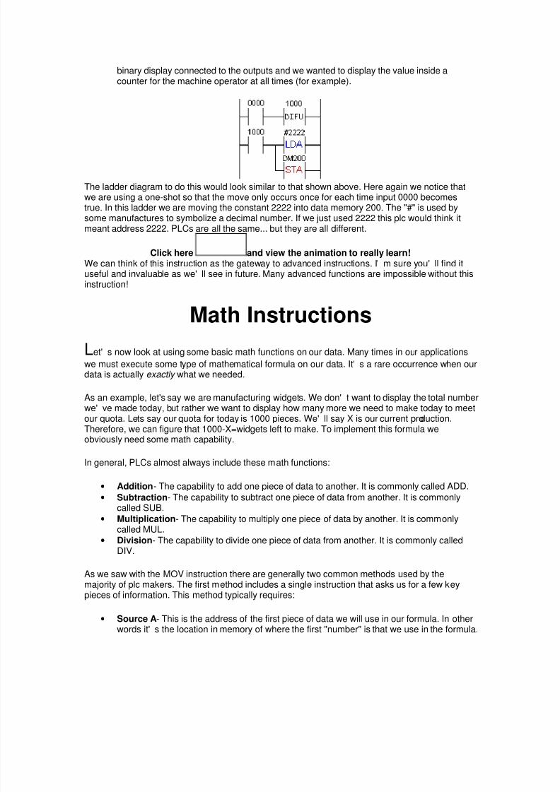
moved to the physical outputs. 0500 would have the least significant bit, 0501 would havethe next bit... 0515 would have the most significant bit. This would be useful if we had abinary display connected to the outputs and we wanted to display the value inside acounter for the machine operator at all times (for example).
The ladder diagram to do this would look similar to that shown above. Notice that we are also using a "difu" instruction here. The reason is simply because if we didn' tthe data would be moved during each and every scan. Sometimes this is a good thing (forexample if we are acquiring data from an A/D module) but other times it' s not (for example anexternal display would be unreadable because the data changes too much). The ladder shows that each time real world input 0000 becomes true, difu will become true foronly one scan. At this time LoaD 1000 will be true and the plc will move the data from datamemory 200 and put it into data memory 201.Simple but effective. If, instead of DM200, we had written 2222 in the symbol we would havemoved (written) the number (constant) 2222 into DM201.The two symbol instruction works in the same method but looks different. To use them we mustalso supply two things, one for each instruction:
• LDA- this instruction is similar to the source of a MOV instruction. This is where the datawe want to move is located. We could write a constant here (2222 for example). Thiswould mean our source data is the number 2222. We could also write a location oraddress of where the data we want to move is located. If we wrote DM100 this wouldmove the data that is located in data memory 100.
• STA- this instruction is similar to the destination of a MOV instruction. We write anaddress here. For example if we write DM201 here the data would be moved into datamemory 201. We could also write 0500 here. This would mean that the data would bemoved to the physical outputs. 0500 would have the least significant bit, 0501 would havethe next bit... 0515 would have the most significant bit. This would be useful if we had a
8/8/2019 6877290-What-is-a-PLC
http://slidepdf.com/reader/full/6877290-what-is-a-plc 31/53
binary display connected to the outputs and we wanted to display the value inside acounter for the machine operator at all times (for example).
The ladder diagram to do this would look similar to that shown above. Here again we notice thatwe are using a one-shot so that the move only occurs once for each time input 0000 becomestrue. In this ladder we are moving the constant 2222 into data memory 200. The "#" is used bysome manufactures to symbolize a decimal number. If we just used 2222 this plc would think itmeant address 2222. PLCs are all the same... but they are all different.
Click here and view the animation to really learn!We can think of this instruction as the gateway to advanced instructions. I' m sure you' ll find it
useful and invaluable as we' ll see in future. Many advanced functions are impossible without thisinstruction! Math Instructions
Let' s now look at using some basic math functions on our data. Many times in our applications
we must execute some type of mathematical formula on our data. It' s a rare occurrence when ourdata is actually exactly what we needed. As an example, let's say we are manufacturing widgets. We don' t want to display the total numberwe' ve made today, but rather we want to display how many more we need to make today to meet
our quota. Lets say our quota for today is 1000 pieces. We' ll say X is our current production.Therefore, we can figure that 1000-X=widgets left to make. To implement this formula weobviously need some math capability.In general, PLCs almost always include these math functions:
• Addition- The capability to add one piece of data to another. It is commonly called ADD. • Subtraction- The capability to subtract one piece of data from another. It is commonly
called SUB.
• Multiplication- The capability to multiply one piece of data by another. It is commonlycalled MUL.
• Division- The capability to divide one piece of data from another. It is commonly called
DIV.
As we saw with the MOV instruction there are generally two common methods used by themajority of plc makers. The first method includes a single instruction that asks us for a few keypieces of information. This method typically requires:
• Source A- This is the address of the first piece of data we will use in our formula. In otherwords it' s the location in memory of where the first "number" is that we use in the formula.

8/8/2019 6877290-What-is-a-PLC
http://slidepdf.com/reader/full/6877290-what-is-a-plc 32/53
• Source B- This is the address of the second piece of data we will use in our formula. Inother words it' s the location in memory of where the second "number" is that we use inthe formula. -NOTE: typically we can only work with 2 pieces of data at a time. In otherwords we can' t work directly with a formula like 1+2+3. We would have to break it up intopieces. Like 1+2=X then X+3= our result.
• Destination- This is the address where the result of our formula will be put. For example,
if 1+2=3, (I hope it still does!), the 3 would automatically be put into this destinationmemory location.
ADD symbolThe instructions above typically have a symbol that looks like that shown above. Of course, theword ADD would be replaced by SUB, MUL, DIV, etc. In this symbol, The source A is DM100, thesource B is DM101 and the destination is DM102. Therefore, the formula is simply whatevervalue is in DM100 + whatever value is in DM101. The result is automatically stored into DM102.
Shown above is how to use math functions on a ladder diagram. Please note that once again weare using a one-shot instruction. As we' ve seen before, this is because if we didn' t use it wewould execute the formula on every scan. Odds are good that we' d only want to execute thefunction one time when input 0000 becomes true. If we had previously put the number 100 intoDM100 and 200 into DM101, the number 300 would be stored in DM102.(i.e. 100+200=300,right??)
ADD symbol (dual method)The dual instruction method would use a symbol similar to that shown above. In this method, wegive this symbol only the Source B location. The Source A location is given by the LDAinstruction. The Destination would be included in the STA instruction.
Shown above is a ladder diagram showing what we mean.The results are the same as the single instruction method shown above.
Click here and view the animation to really learn!What would happen if we had a result that was greater than the value that could be stored in amemory location? Typically the memory locations are 16-bit locations. (more about number types in a later chapter)In plain words this means that if the number is greater than 65535 (2^16=65536) it is too big to fit.

8/8/2019 6877290-What-is-a-PLC
http://slidepdf.com/reader/full/6877290-what-is-a-plc 33/53
Then we get what' s called an overflow. Typically the plc turns on an internal relay that tells us anoverflow has happened. Depending on the plc, we would have different data in the destinationlocation. (DM102 from example) Most PLCs put the remainder here. Some use 32-bit math which solves the problem. (except for really big numbers!) If we' re doingdivision, for example, and we divide by zero (illegal) the overflow bit typically turns on as well.Suffice it to say, check the overflow bit in your ladder and if its true, plan appropriately. Many PLCs also include other math capabilities. Some of these functions could include:
• Square roots • Scaling • Absolute value • Sine • Cosine • Tangent
• Natural logarithm • Base 10 logarithm • X^Y (X to the power of Y)
• Arcsine (tan, cos)
• and more....check with the manufacturer to be sure.
Some PLCs can use floating point math as well. Floating point math is simply using decimalpoints. In other words, we could say that 10 divided by 3 is 3.333333 (floating point). Or we couldsay that 10 divided by 3 is 3 with a remainder of 1(long division). Many micro/mini PLCs don' tinclude floating point math. Most larger systems typically do. Understand the theory and we can always learn how our manufacturer of choice does it.
Number SystemsBefore we get too far ahead of ourselves, let' s take a look at the various number systems used
by PLCs.
Many number systems are used by PLCs. Binary and Binary Coded Decimal are popular whileoctal and hexadecimal systems are also common.Let' s look at each:As we do, consider the following formula (Math again!):
Nbase= Ddigit * R^unit + .... D1R^1 + D0R^0 where D=the value of the digit and R= # of digit symbols used in the given number system.The "*" means multiplication. ( 5 * 10 = 50)The "^" means "to the power of".
As you' ll recallany number raised to the power of 0 is 1. 10^1=10, 10^2 is 10x10=100, 10^3 is10x10x10=1000, 10^4 is 10x10x10x10=10000... This lets us convert from any number system back into decimal. Huh? Read on...
• Decimal- This is the numbering system we use in everyday life. (well most of us doanyway!) We can think of this as base 10 counting. It can be called as base 10 becauseeach digit can have 10 different states. (i.e. 0-9) Since this is not easy to implement in anelectronic system it is seldom, if ever, used. If we use the formula above we can find out

8/8/2019 6877290-What-is-a-PLC
http://slidepdf.com/reader/full/6877290-what-is-a-plc 34/53
what the number 456 is. From the formula:Nbase= Ddigit * R^unit + .... D1R^1 + D0R^0 we have (since we're doing base 10, R=10)
N10= D410^2 + D510^1 + D610^0= 4*100 + 5*10 + 6*= 400 + 50 + 6= 456.
• Binary- This is the numbering system computers and PLCs use. It was far easier todesign a system in which only 2 numbers (0 and 1) are manipulated (i.e. used).The binary system uses the same basic principles as the decimal system. In decimal wehad 10 digits. (0-9) In binary we only have 2 digits (0 and 1). In decimal we count:0,1,2,3,4,5,6,7,8,9, and instead of going back to zero, we start a new digit and then startfrom 0 in the original digit location.In other words, we start by placing a 1 in the second digit location and begin countingagain in the original location like this 10,11,12,13, ... When again we hit 9, we incrementthe second digit and start counting from 0 again in the original digit location. Like20,21,22,23.... of course this keeps repeating. And when we run out of digits in thesecond digit location we create a third digit and again start from scratch.(i.e. 99, 100, 101,102...)Binary works the same way. We start with 0 then 1. Since there is no 2 in binary we mustcreate a new digit.Therefore we have 0, 1, 10, 11 and again we run out of room. Then we create anotherdigit like 100, 101, 110, 111. Again we ran out of room so we add another digit... Do youget the idea?The general conversion formula may clear things up:Nbase= Ddigit * R^unit + .... D1R^1 + D0R^0.Since we' re now doing binary or base 2, R=2. Let' s try to convertthe binary number 1101back into decimal.
N10= D1 * 2^3 + D1 * 2^2 + D0 * 2^1 + D1 * 2^0= 1*8 + 1*4 + 0*2 + 1*1= 8 + 4 +0 +1= 13
(if you don' t see where the 8,4,2, and 1 came from, referto the table below).Now we can see that binary 1101 is the same as decimal 13. Try translating binary 111. Youshould get decimal 7. Try binary 10111. You should get decimal 23. Here' s a simple binary chart for reference. The top row shows powers of 2 while the bottom rowshows their equivalent decimal value.
Binary Number Conversions2^15 2^14 2^13 2^12 2^11 2^10 2^9 2^8 2^7 2^6 2^5 2^4 2^3 2^2 2^1 2^0
32768 16384 8192 4096 2048 1024 512 256 128 64 32 16 8 4 2 1• Octal- The binary number system requires a ton of digits to represent a large number.
Consider that binary 11111111 is only decimal 257. A decimal number like 1,000,000 ("1million") would need a lot of binary digits! Plus it' s also hard for humans to manipulatesuch numbers without making mistakes.Therefore several computer/plc manufacturers started to implement the octal numbersystem.This system can be thought of as base8 since it consists of 8 digits. (0,1,2,3,4,5,6,7)So we count like 0,1,2,3,4,5,6,7,10,11,12...17,20,21,22...27,30,...

8/8/2019 6877290-What-is-a-PLC
http://slidepdf.com/reader/full/6877290-what-is-a-plc 35/53
Using the formula again, we can convert an octal number to decimal quite easily. Nbase= Ddigit * R^unit + .... D1R^1 + D0R^0 So octal 654 would be: (remember that here R=8)
N10= D6 * 8^2 + D5 * 8^1 + D4 * 8^0= 6*64 + 5*8 + 4*1= 384 +40 +4= 428
(if you don' t see where the white 64,8 and 1 came from,refer to the table below).Now we can see that octal 321 is the same as decimal 209. Try translating octal 76. You shouldget decimal 62. Try octal 100. You should get decimal 64. Here' s a simple octal chart for your reference. The top row shows powers of 8 while the bottomrow shows their equivalent decimal value.
Octal Number Conversions8^7 8^6 8^5 8^4 8^3 8^2 8^1 8^0
2097152 262144 32768 4096 512 64 8 1Lastly, the octal system is a convenient way for us to express or write binary numbers in plc
systems. A binary number with a large number of digits can be conveniently written in an octalform with fewer digits. This is because 1 octal digit actually represents 3 binary digits. Believe me that when we start working with register data or address locations in the advancedchapters it becomes a great way of expressing data. The following chart shows what we' rereferring to:
Binary Number with its Octal Equivalent1 1 1 0 0 1 0 0 1 1 1 0 0 1 0 11 6 2 3 4 5
From the chart we can see that binary 1110010011100101 is octal 162345. (decimal 58597) Aswe can see, when we think of registers, it' s easier to think in octal than in binary. As you' llsoonsee though, hexadecimal is the best way to think. (really)
• Hexadecimal-The binary number system requires a ton of digits to represent a largenumber. The octal system improves upon this. The hexadecimal system is the bestsolution however, because it allows us to use even less digits. It is therefore the mostpopular number system used with computers and PLCs. (we should learn each onethough)The hexadecimal system is also referred to as base 16 or just simply hex. As the namebase 16 implies, it has 16 digits. The digits are0,1,2,3,4,5,6,7,8,9,A,B,C,D,E,F.So we count like0,1,2,3,4,5,6,7,8,9,A,B,C,D,E,F,10,11,12,13,...1A,1B,1C,1D,1E,1F,20,21... 2A,2B,2C,2D,2E,2F,30...Using the formula again, we can convert a hex number to decimal quite easily.Nbase= Ddigit * R^unit + .... D1R^1 + D0R^0
So hex 6A4 would be:(remember here that R=16) N10= D6 * 16^2 + DA * 16^1 + D4 * 16^0
= 6*256 + A(A=decimal10)*16 + 4*1= 1536 +160 +4= 1700
(if you don' t see where the 256,16 and 1 came from,refer to the table below)

8/8/2019 6877290-What-is-a-PLC
http://slidepdf.com/reader/full/6877290-what-is-a-plc 36/53
Now we can see that hex FFF is the same as decimal 4095. Try translating hex 76. You shouldget decimal 118. Try hex 100. You should get decimal 256.Here' s a simple hex chart for reference. The top row shows powers of 16 while the bottom rowshows their equivalent decimal value. Notice that the numbers get large rather quickly!
Hex Number Conversions16^8 16^7 16^6 16^5 16^4 16^3 16^2 16^1 16^0
4294967296 268435456 16777216 1048576 65536 4096 256 16 1Finally, the hex system is perhaps the most convenient way for us to express or write binarynumbers in plc systems. A binary number with a large number of digits can be convenientlywritten in hex form with fewer digits than octal. This is because 1 hex digit actually represents 4binary digits. Believe me that when we start working with register data or address locations in the advancedchapters it becomes the best way of expressing data. The following chart shows what we' rereferring to:
Binary Number with its Hex Equivalent0 1 1 1 0 1 0 0 1 0 1 0 0 1 0 1
7 4 A 5From the chart we can see that binary 0111010010100101 is hex 74A5. (decimal 29861) As we
can see, when we think of registers, it' s far easier to think in hex than inbinary or octal. 4 digits go a long way after some practice! Boolean Math
Let' s now take a look at some simple "boolean math". Boolean math lets us do some vary basic
functions with the bits in our registers. These basic functions typically include AND, OR and XORfunctions. Each is described below.
• AND- This function enables us to use the truth table below. Here, we can see that theAND function is very much related to multiplication. We see this because the only timethe Result is true (i.e. 1) is when both operators A AND B are true (i.e. 1).The AND instruction is useful when your plc doesn' t have a masking function. Oh yeah, amasking function enables a bit in a register to be "left alone" when working on a bit level.This is simply because any bit that is ANDed with itself will remain the value it currentlyis. For example, if you wanted to clear ( make them 0) only 12 bits in a 16 bit register youmight AND the register with 0' s everywhere except in the 4 bits you wanted to maintainthe status of.
See the truth table below to figure out what we mean. (1 AND 1 = 1, 0 AND 0= 0) Result = A AND B
A B Result0 0 01 0 00 1 01 1 1• OR- This functions based upon the truth table below. Here, we can see that the OR
function is very much related to addition. We see this because the only time the Result istrue (i.e. 1) is when operator A OR B is true (i.e. 1). Obviously, when they are both truethe result is true. (If A OR B is true...)

8/8/2019 6877290-What-is-a-PLC
http://slidepdf.com/reader/full/6877290-what-is-a-plc 37/53
Result = A OR BA B Result0 0 01 0 10 1 11 1 1• EXOR- This function enables us to use the truth table below. Here, we can see that the
EXOR (XOR) function is not related to anything I can think of ! An easy way to rememberthe results of this function is to think that A and B must be one or the other case,exclusively. Huh?In other words, they must be opposites of each other. When they are both the same (i.e.A=B) the result is false (i.e. 0).This is sometimes useful when you want to compare bits in 2 registers and highlightwhich bits are different. It' s also needed when we calculate some checksums. Achecksum is commonly used as error checking in some communications protocols.
Result = A XOR BA B Result0 0 01 0 10 1 11 1 0
The ladder logic instructions are commonly called AND, ANDA, ANDW, OR, ORA, ORW,XOR, EORA XORW. As we saw with the MOV instruction there are generally two common methods used by themajority of plc makers. The first method includes a single instruction that asks us for a few keypieces of information. This method typically requires:
• Source A- This is the address of the first piece of data we will use. In other words its thelocation in memory of where the A is.
• Source B- This is the address of the second piece of data we will use. In other words itsthe location in memory of where the B is.
• Destination- This is the address where the result will be put. For example, if A AND B =0 the result (0) would automatically be put into this destination memory location.
AND symbolThe instructions above typically have a symbol that looks like that shown here. Of course, theword AND would be replaced by OR or XOR. In this symbol, The source A is DM100, the sourceB is DM101 and the destination is DM102. Therefore, we have simply created the equationDM100 AND DM101 = DM102. The result is automatically stored into DM102.
The boolean functions on a ladder diagram are shown below.

8/8/2019 6877290-What-is-a-PLC
http://slidepdf.com/reader/full/6877290-what-is-a-plc 38/53
Please note that once again we are using a one-shot instruction. As we' ve seen before, this isbecause if we didn' t use it, we would execute the instruction on every scan. Odds are good thatwe' d only want to execute the function one time when input 0000 becomes true.
AND symbol (dual instruction method)The dual instruction method would use a symbol similar to that shown above. In this method, wegive this symbol only the Source B location. The Source A location is given by the LDAinstruction. The Destination would be included in the STA instruction. Below is a ladder diagram showing what is meant:
The results are the same as the single instruction method shown above. It should be noted thatalthough the symbol and ladder diagram above show the AND instruction, OR or EXOR can beused as well. Simply substitute the word "AND" within the instruction to be either "OR" or"EXOR". The results will be the same as shown in their respective truth tables.We should always remember that the theory is most important. If we can understand the theory ofwhy things happen as they do, we can use anybody' s plc. If we refer to the manufacturers
documentation we can find out the details for the particular plc we are using. Try to find the theoryin that documentation and you might come up short. The details are insignificant while the theoryis very significant.
DC InputsLet' s now take a look at howthe input circuits of a plc work. This will give us a better
understanding of how we should wire them up. Bad things can happen if we wire them upincorrectly!Typically, dc input modules are available that will work with 5, 12, 24, and 48 volts. Be sure topurchase the one that fits your needs based upon the input devices you will use.We' ll first look at how the dc inputs work. DC input modules allow us to connect either PNP(sourcing) or NPN (sinking) transistor type devices to them. If we are using a regular switch (i.e.toggle or pushbutton, etc.) we typically don' t have to worry about whether we wire it as NPN orPNP. We should note that most PLCs won' t let us mix NPN and PNP devices on the samemodule. When we are using a sensor (photo-eye, prox, etc.) we do, however, have to worry about

8/8/2019 6877290-What-is-a-PLC
http://slidepdf.com/reader/full/6877290-what-is-a-plc 39/53
its output configuration. Always verify whether it's PNP or NPN. (Check with the manufacturerwhen unsure) The difference between the two types is whether the load (in our case, the plc is the load) isswitched to ground or positive voltage. An NPN type sensor has the load switched to groundwhereas a PNP device has the load switched to positive voltage. Below is what the outputs look like for NPN and PNP sensors.
On the NPN sensor we connect one output to the PLCs input and the other output to the powersupply ground. If the sensor is not powered from the same supply as the plc, we should connectboth grounds together. NPN sensors are most commonly used in North America. Many engineers will say that PNP is better (i.e. safer) because the load is switched to ground, butwhatever works for you is best. Just remember to plan for the worst.On the PNP sensor we connect one output to positive voltage and the other output to the PLCsinput. If the sensor is not powered from the same supply as the plc, we should connect both V+' stogether. PNP sensors are most commonly used in Europe.
Inside the sensor, the transistor is just acting as a switch. The sensors internal circuit tells theoutput transistor to turn on when a target is present. The transistor then closes the circuitbetween the 2 connections shown above. (V+ and plc input).

8/8/2019 6877290-What-is-a-PLC
http://slidepdf.com/reader/full/6877290-what-is-a-plc 40/53
The only things accessible to the user are the terminals labeled COMMON, INPUT 0000, INPUT
0001, INPUTxxxx... The common terminal either gets connected to V+ or ground. Where it' sconnected depends upon the type of sensor used. When using an NPN sensor this terminal isconnected to V+. When using a PNP sensor this terminal is connected to 0V (ground).A common switch (i.e. limit switch, pushbutton, toggle, etc.) would be connected to the inputs in asimilar fashion. One side of the switch would be connected directly to V+. The other end goes tothe plc input terminal. This assumes the common terminal is connected to 0V (ground). If thecommon is connected to V+ then simply connect one end of the switch to 0V (ground) and theother end to the plc input terminal. The photocouplers are used to isolate the PLCs internal circuit from the inputs. This eliminatesthe chance of any electrical noise entering the internal circuitry. They work by converting theelectrical input signal to light and then by converting the light back to an electrical signal to be
processed by the internal circuit. AC Inputs
Now that we understand how dc inputs work, let' s take a close look at ac inputs. Anac voltage is
non-polarized. Put simply, this means that there is no positive or negative to "worry about ".However, ac voltage can be quite dangerous to work with if we are careless. (Remember when you stuck the knife in the toaster and got a shock? Be careful ) Typically, ac input modulesare available that will work with 24, 48, 110, and 220 volts. Be sure to purchase the one that fitsyour needs based upon the input devices (voltage) you will use.

8/8/2019 6877290-What-is-a-PLC
http://slidepdf.com/reader/full/6877290-what-is-a-plc 41/53
OUCH... use care!!AC input modules are less common these days than dc input modules. The reason being thattoday' s sensors typically have transistor outputs. A transistor will not work with an ac voltage.Most commonly, the ac voltage is being switched through a limit switch or other switch type. Ifyour application is using a sensor it probably is operating on a dc voltage.
We typically connect an ac device to our input module as shown above. Commonly the ac "hot"wire is connected to the switch while the "neutral" goes to the plc common. The ac ground (3rdwire where applicable) should be connected to the frame ground terminal of the plc.(not shown)
As is true with dc, ac connections are typically color coded so that the individual wiring the deviceknows which wire is which. This coding varies from country to country but in the US is commonlywhite (neutral), black (hot) and green (3rd wire ground when applicable). Outside the US it' scommonly coded as brown (hot), blue (neutral) and green with a yellow stripe (3rd wire groundwhere applicable).
The PLCs ac input module circuit typically looks like this:

8/8/2019 6877290-What-is-a-PLC
http://slidepdf.com/reader/full/6877290-what-is-a-plc 42/53
The only things accessible to the user are the terminals labeled COMMON, INPUT 0000,INPUTxxxx... The common terminal gets connected to the neutral wire. A common switch (i.e. limit switch, pushbutton, toggle, etc.) would be connected to the inputterminals directly. One side of the switch would be connected directly to INPUT XXX. The otherend goes to the ac hot wire. This assumes the common terminal is connected to neutral. Alwayscheck the manufacturers specifications before wiring, to be sure AND SAFE. The photocouplers are used to isolate the PLCs internal circuit from the inputs. This eliminatesthe chance of any electrical noise entering the internal circuitry. They work by converting theelectrical input signal to light and then by converting the light back to an electrical signal to beprocessed by the internal circuit. One last note, typically an ac input takes longer than a dc input for the plc to see. In most cases itdoesn' t matter to the programmer because an ac input device istypically a mechanical switchand mechanical devices are slowwwwww. It' s quite common for a plc to require that the input beon for 25 or more milliseconds before it' s seen. This delay is required because of the filteringwhich is needed by the plc internal circuit. Remember that the plc internal circuit typically workswith 5 or less volts dc.
Relay OutputsBy now we should have a good understanding of how the inputs are used. Next up is the output
circuits.One of the most common types of outputs available is the relay output. A relay can be used withboth AC and DC loads. A load is simply a fancy word for whatever is connected to our outputs.We call it a load because we are "loading the output" with something. If we connected no load tothe output (i.e. just connect it directly to a power supply) we would certainly damage the outputs.This would be similar to replacing the lightbulb in the lamp you' re using to read this with a piece ofwire. If you did this, the lamp would draw a tremendous amount of current from the outlet andcertainly pop your circuit breaker or blow your fuse or your brains. (Take our word. Please don't try it! Extremely dangerous! )

8/8/2019 6877290-What-is-a-PLC
http://slidepdf.com/reader/full/6877290-what-is-a-plc 43/53
Some common forms of a load are a solenoid, lamp, motor, etc. These "loads" come in all sizes.Electrical sizes, that is. Always check the specifications of your load before connecting it to theplc output. You always want to make sure that the maximum current it will consume is within thespecifications of the plc output. If it is not within the specifications (i.e. draws too much current) itwill probably damage the output. When in doubt, double check with the manufacturer to see if itcan be connected without potential damage. Some types of loads are very deceiving. These deceiving loads are called "inductive loads".These have a tendency to deliver a "back current " when they turn on. This back current is like avoltage spike coming through the system. A good example of an inductive load that most of us see about 6 months per year is an airconditioning unit. Perhaps in your home you have an air conditioner. (unless you live in the arcticyou probably do!) Have you ever noticed that when the air conditioner "kicks on " the lights dim fora second or two. Then they return to their normal brightness. This is because when the airconditioner turns on it tries to draw a lot of current through your wiring system. After this initial"kick" it requires less current and the lights go back to normal. This could be dangerous to yourPLCs output relays. It can be estimated that this kick is about 30 times the rated current of theload. Typically a diode, varistor, or other "snubber" circuit should be used to help combat any
damage to the relay. Enough said. Let' s see how we can use these outputs in the "real plc world".
Shown above is a typical method of connecting our outputs to the plc relays. Although ourdiagram shows the output connected to an AC supply, DC can be used as well. A relay is non-polarized and typically it can switch either AC or DC. Here the common is connected to one endof our power supply and the other end of the supply is connected to the load. The other half of ourload gets connected to the actual plc output you have designated within your ladder program.

8/8/2019 6877290-What-is-a-PLC
http://slidepdf.com/reader/full/6877290-what-is-a-plc 44/53
The relay is internal to the plc. Its circuit diagram typically looks like that shown above. When our
ladder diagram tells the output to turn on, the plc will internally apply a voltage to the relay coil.This voltage will allow the proper contact to close. When the contact closes, an external current isallowed to flow through our external circuit. When the ladder diagram tells the plc to turn off theoutput, it will simply remove the voltage from the internal circuit thereby enabling the outputcontact to release. Our load will than have an open circuit and will therefore be off. Simple, isn'tit?
Transistor OutputsThe next type of output we should learn about is our transistor type outputs. It is important to
note that a transistor can only switch a dc current. For this reason it cannot be used with an ACvoltage. We can think of a transistor as a solid-state switch. Or more simply put, an electrical switch. Asmall current applied to the transistors "base " (i.e. input) lets us switch a much larger currentthrough its output. The plc applies a small current to the transistor base and the transistor output"closes ". When it' s closed, the deviceconnected to the plc output will be turned on. The above isa very simple explanation of a transistor. There are, of course, more details involved but we don' tneed to get too deep. We should also keep in mind that as we saw before with the input circuits, there are generallymore than one type of transistor available. Typically a plc will have either NPN or PNP typeoutputs. The "physical " type of transistor used also varies from manufacturer to manufacturer.
Some of the common types available are BJT and MOSFET. A BJT type (Bipolar JunctionTransistor) often has less switching capacity (i.e. it can switch less current) than a MOS-FET(Metal Oxide Semiconductor- Field Effect Transistor) type. The BJT also has a slightly fasterswitching time. Once again, please check the output specifications of the particular plc you aregoing to use. Never exceed the manufacturers maximum switching current.

8/8/2019 6877290-What-is-a-PLC
http://slidepdf.com/reader/full/6877290-what-is-a-plc 45/53
Shown above is how we typically connect our output device to the transistor output. Please notethat this is an NPN type transistor. If it were a PNP type, the common terminal would mostlikely be connected to V+ and V- would connect to one end of our load. Note that since this is aDC type output we must always observe proper polarity for the output. One end of the load isconnected directly to V+ as shown above. Let' s take a moment and see what happens inside the output circuit. Shown below is a typicaloutput circuit diagram for an NPN type output.
Notice that as we saw with the transistor type inputs, there is a photocoupler isolating the "real world " from the internal circuit. When the ladder diagram calls for it, the internal circuit turns onthe photocoupler by applying a small voltage to the LED side of the photocoupler. This makes theLED emit light and the receiving part of the photocoupler will see it and allow current to flow. Thissmall current will turn on the base of the output transistor connected to output 0500. Therefore,whatever is connected between COM and 0500 will turn on. When the ladder tells 0500 to turnoff, the LED will stop emitting light and hence the output transistor connected between 0500 andCOM will turn off. One other important thing to note is that a transistor typically cannot switch as large a load as arelay. Check the manufacturers specifications to find the largest load it can safely switch. If theload current you need to switch exceeds the specification of the output, you can connect the plcoutput to an external relay. Then connect the relay to the large load. You may be thinking, "why
not just use a relay in the first place "? The answer is because a relay is not always the correctchoice for every output. A transistor gives you the opportunity to use external relays when andonly when necessary.In summary, a transistor is fast, switches a small current, has a long lifetime and works with dconly. Whereas a relay is slow, can switch a large current, has a shorter lifetime and works with acor dc. Select the appropriate one based upon your actual application needs.

8/8/2019 6877290-What-is-a-PLC
http://slidepdf.com/reader/full/6877290-what-is-a-plc 46/53
Communications History
By far, the most popular method of communicating with external devices is by using the "RS-
232" communications method. Communication with external devices is viewed by many plcprogrammers to be difficult if not "all but impossible" to understand. This is far from true! It' s not"black art", "witchcraft" or "weird science". Read on...All plc communication systems have their roots in the old telegraph we may have seen in the oldmovies. (Remember the guy working at the train station with the arm band and plastic visor?)Early attempts to communicate electronically over long distances began as early as the late1700' s. In 1810 a German man (von Soemmering) was using a device with 26 wires (1 for eachletter of the alphabet) attached to the bottom of an aquarium. When current passed through thewires, electrolytic action produced small bubbles. By choosing the appropriate wires to energize,he was able to send encoded messages "via bubbles". (It' s true...really) This then caught theattention of the military and the race to find a system was on. In 1839, 2 Englishmen, Cooke and Wheatstone, had a 13 mile telegraph in use by a Britishrailroad. Their device had 5 wires powering small electromagnets which deflected low-massneedles. By applying current to different combinations of 2 wires at a time the needles weredeflected so that they pointed to letters of the alphabet arranged in a matrix. This "2 of 5" codeonly allowed 20 combinations so the letters "z,v,u,q,j and c" were omitted. This telegraph was abig step for the time, but the code was not binary (on/off) but rather it was trinary (the needlemoved left,right,or not at all).
The biggest problems with these devices was the fact that they were parallel (required multiple
wires). Cooke and Wheatstone eventually made a two wire device but the first practical fully serialbinary system generally gets credited to S.F.B. Morse. In Morse code, characters are symbolizedby dots and dashes(binary- 1' s and 0' s). Morse' s first system isn' t like we see today in the movies.(It' s on display at the Smithsonian in DC if you want to see it) It actually had a needle contacting arotating drum of paper that made a continuous mark. By energizing an electromagnet the needlewould "bounce" away from the paper creating a space. Very soon telegraph operators noticedthat they didn' t have to look at the paper to read the code but they could interpret the code by thesound the needle made when scratching the paper. So this device was replaced by a sounderthat produced click sounds instead of paper etchings. Teleprinters came later, and todays serial

8/8/2019 6877290-What-is-a-PLC
http://slidepdf.com/reader/full/6877290-what-is-a-plc 47/53

8/8/2019 6877290-What-is-a-PLC
http://slidepdf.com/reader/full/6877290-what-is-a-plc 48/53

8/8/2019 6877290-What-is-a-PLC
http://slidepdf.com/reader/full/6877290-what-is-a-plc 49/53
RS-232 Communications (software)
Now that we understand the hardware part of the picture, let' s dive right into the software part.
We' ll take a look at each part of the puzzle by defining a few of the common terms.Ever wondered what phrases like 9600-8-N-1 meant? Do you use software-handshaking or hardware-handshaking at formal parties for a greeting? If you're not sure, read on!
• ASCII is a human-readable to computer-readable translation code. (i.e. eachletter/number is translated to 1' s and 0' s) It' s a 7-bit (a bit is a 1 or a 0) code, so we cantranslate 128 characters. (2^7 is 128) Character sets that use the 8th bit do exist but theyare not true ASCII. Below is an ASCII chart showing its "human-readable" representation.We typically refer to the characters by using hexadecimal terminology. "0" is 30h, "5" is35h, "E" is 45h, etc. (the "h" simple means hexadecimal)
most significant bits 0 1 2 3 4 5 6 70 space 0 @ P ` p1 XON ! 1 A Q a q2 STX " 2 B R b r3 ETX XOFF # 3 C S c s4 $ 4 D T d t5 NAK % 5 E U e u6 ACK & 6 F V f v7 ' 7 G W g w8 ( 8 H X h x9 ) 9 I Y i yA LF * : J Z j zB + ; K [ k {C , < L \ l |D CR - = M ] m }E . > N ^ n ~
least
sig.bits
F
/
?
O
_
o
• start bit- In RS-232 the first thing we send is called a start bit. This start bit ("invented"during WW1 by Kleinschmidt) is a synchronizing bit added just before each character weare sending. This is considered a SPACE or negative voltage or a 0.
• stop bit- The last thing we send is called a stop bit. This stop bit tells us that the lastcharacter was just sent. Think of it as an end-of -character bit. This is considered aMARK or positive voltage or a 1. The start and stop bits are commonly called framing bitsbecause they surround the character we are sending.

8/8/2019 6877290-What-is-a-PLC
http://slidepdf.com/reader/full/6877290-what-is-a-plc 50/53
• parity bit- Since most plcs/external equipment are byte-oriented (8 bits=1byte) it seemsnatural to handle data as a byte. Although ASCII is a 7-bit code it is rarely transmittedthat way. Typically, the 8th bit is used as a parity bit for error checking. This method oferror checking gets its name from the math idea of parity. (remember the odd-evenproperty of integers? I didn' t think so.) In simple terms, parity means that all characterswill either have an odd number of 1' s or an even number of 1' s.
Common forms of parity are None, Even, and Odd. (Mark and Space aren' t very commonso I won' t discuss them). Consider these examples:send "E" (45h or 1000101b(inary))In parity of None, the parity bit is always 0 so we send 10001010.In parity of Even we must have an Even number of 1' s in our total character so theoriginal character currently has 3 1' s (1000101) therefore our parity bit we will add mustbe a 1. (10001011) Now we have an even number of 1' s.In Odd parity we need an odd number of 1' s. Since our original character already has anodd number of 1' s (3 is an odd number, right?) our parity bit will be a 0. (10001010)During transmission, the sender calculates the parity bit and sends it. The receivercalculates parity for the 7-bit character and compares the result to the parity bit received.If the calculated and real parity bits don' t match, an error occurred an we actappropriately.It' s strange that this parity method is so popular. The reason is becauseit' s only effective
half the time. That is, parity checking can only find errors that effect an odd number ofbits. If the error affected 2 or 4 or 6 bits the method is useless. Typically, errors arecaused by noise which comes in bursts and rarely effects 1 bit. Block redundancy checksare used in other communication methods to prevent this.
• Baud rate- I' ll perpetuate the incorrect meaning since it' s most commonly usedincorrectly. Think of baud rate as referring to the number of bits per second that are beingtransmitted. So 1200 means 1200 bits per second are being sent and 9600 means 9600bits are being transmitted every second. Common values (speeds) are 1200, 2400, 4800,9600, 19200, and 38400.
• RS232 data format- (baud rate-data bits-parity-stop bits) This is the way the data formatis typically specified. For example, 9600-8-N-1 means a baud rate of 9600, 8 data bits,parity of None, and 1 stop bit.
The picture below shows how data leaves the serial port for the character "E" (45h 100 0101b)and Even parity.
Another important thing that is sometimes used is called software handshaking (flow control). Likethe hardware handshaking we saw in the previous chapter, software handshaking is used tomake sure both devices are ready to send/receive data. The most popular "character flow control"is called XON/XOFF. It' s very simple to understand. Simply put, the receiver sends the XOFFcharacter when it wants the transmitter to pause sending data. When it' s ready to receive dataagain, it sends the transmitter the XON character. XOFF is sometimes referred to as the holdoff
character and XON as the release character.
The last thing we should know about is delimiters. A delimiter is simply added to the end of amessage to tell the receiver to process the data it has received. The most common is the CR orthe CR and LF pair. The CR (carriage return) is like the old typewriters. (remember them??)When you reached the end of a line while typing, a bell would sound. You would then grab thehandle and move the carriage back to the start. In other words, you returned the carriage to thebeginning. (This is the same as what a CR delimiter will do if you view it on a computer screen.)The plc/external device receives this and knows to take the data from its buffer. (where the datais stored temporarily before being processed) An LF (line feed) is also sometimes sent with theCR character. If viewed on a computer screen this would look like what happens on the typewriter

8/8/2019 6877290-What-is-a-PLC
http://slidepdf.com/reader/full/6877290-what-is-a-plc 51/53
when the carriage is returned and the page moves down a line so you don' t type over what you just typed.Sometimes an STX and ETX pair is used for transmission/reception as well. STX is "start of text"and ETX is "end of text". The STX is sent before the data and tells the external device that data iscoming. After all the data has been sent, an ETX character is sent. Finally, we might also come across an ACK/NAK pair. This is rarely used but it should be notedas well. Essentially, the transmitter sends its data. If the receiver gets it without error, it sendsback an ACK character. If there was an error, the receiver sends back a NAK character and thetransmitter resends the data.RS-232 has a lot of information to absorb, so feel free to reread it. It' s not so difficult if youtake your time and think about each step. Other communication methods get easier!
Using RS-232 with Ladder Logic
Now that we understand what RS-232 is/means let' s see how to use it with our plc.
We should start out as always, remembering that a plc is a plc is a plc... In other words,understand the theory first and then figure out how our manufacturer of choice "makes it work".Some manufacturers include RS-232 communication capability in the main processor. Some usethe "programming port" for this. Others require you to purchase (i.e. spend extra $' s) a module to"talk RS-232" with an external device.What is an external device, you maybe asking? The answer is difficult because there are so manyexternal devices. It may be an operator interface, an external computer, a motor controller, arobot, a vision system, a ... get the point??To communicate via RS-232 we have to setup a few things. Ask yourself the following questions:
• Where, in data memory, will we store the data to be sent? Essentially we have to storethe data we will send... somewhere. Where else but in our data memory!
• Where, in data memory, will we put the data we receive from the external device? • How will we tell the plc when it' s time to sendour data (the data we stored in data
memory) out the serial port? • How will we know when we have received data from our external device?
If you know the above, then the rest is easy. If you don' t know the above, then make somethingup and now the rest is easy. Huh??? Simple, pick a memory area to work with and figure out if wecan choose the internal relays to use to send and receive data or if the plc has ones that arededicated to this purpose. Sounds too simple?? (No way, it is simple!!)Before we do it, let' s get some more technical terms out of the way so we' re on the same playingfield.
• Buffer- A buffer is a fancy technical word that means a plastic bag . In other words, it' s a
temporary storage location where the plc or external device stores data it has received(or is waiting to send) via RS-232. When I go to the supermarket to buy my favorite tvdinners, I carry them home in a plastic bag. The plastic bag is not a permanent place formy food (are tv dinners really food??) but rather a temporary storage place for them untilI get home. When I get home, I take them out of the bag and cook them. Thesupermarket was the external device where I got the data (tv dinners) from and mymicrowave is the plc. The plastic bag was the buffer (temporary storage place) that washolding my data (tv dinner) until I took them out to use (i.e cook).

8/8/2019 6877290-What-is-a-PLC
http://slidepdf.com/reader/full/6877290-what-is-a-plc 52/53
• String- A string is a cool way of saying "a bunch of characters". The word "hello" is astring. It' s a bunch of characters (i.e. h-e-l-l-o) that are connected (strung) together tomean something useful. "43770" is also a string. Although it makes no sense to us, it maymean something valuable to your plc or external device. It could be a command that tellsyour robot to send out its current coordinates. (or it could simply be the word "hello"upside down)
•
Concatenate- This word is a mouthfull. Simply put, it means to combine 2 stringstogether to make one string. An example is combining the 2 strings "laser" and "jet"together to make one string... "laserjet".
With the mumbo-jumbo out of the way let' s see it in action. Again, the memory locations andrelays vary by manufacturer but the theory is universal.
1. We assign memory locations DM100 through DM102 to be where we' ll put our databefore we send it out the serial port. Note- Many plcs have dedicated areas of memoryfor this and only this purpose.
2. We' ll assign internal relay 1000 to be our send relay. In other words, when we turn on1000 the plc will send the data in DM100-DM102 out the serial port to our externaldevice. Note again- Many plcs have dedicated relays (special utility relays) for this and
only this purpose. It' s great when the manufacturer makes our life easy!
We' ll send the string "alr" out the plc serial port to an operator interface when our temp sensorinput turns on. This means our oven has become too hot. When the operator interface receivesthis string it will displayed an alarm message for the operator to see. Look back on the ASCIIchart and you' ll see that "alr" is hexadecimal 61, 6C, 72. (a=61, l=6C, r=72) We' ll write theseASCII characters (in hexadecimal form) into the individual data memory locations. We' ll useDM100-102. How? Remember the LDA or MOV instruction? We' ll turn on our send relay (1000)when our temperature sensor (0000) turns on. The ladder is shown below.
Some plcs may not have dedicated internal relays that send out our data through the RS-232port. We may have to assign them manually. Further, some plcs will have a special instruction totell us where the data is stored and when to send the data. This instruction is commonly calledAWT (ASCII Write) or RS. The theory is always the same though. Put the data in a memorylocation and then turn on a relay to send the data.

8/8/2019 6877290-What-is-a-PLC
http://slidepdf.com/reader/full/6877290-what-is-a-plc 53/53