6.9.6 dual-band feed experiments - w1ghz.org · 2003. 2. 12. · 6.9.6 dual-band feed experiments i...
TRANSCRIPT

6.9.6 Dual-band feed experiments
I was impressed with the performance of the dual-band feeds for 10 and 24 GHz; I hypothesized thatthe wider frequency separation might provide better results than the more closely spaced frequenciesof the W5LUA feeds. A few experiments, at least in computer simulation, could test this hypothesis.Two of the possible pairs of bands with wider separation are 2304 and 5760 MHz, a 2.5:1 frequencyratio, and 3456 and 10368 MHz, a 3:1 frequency ratio.
Since WR-90 waveguide for 10 GHz is readily available, perhaps we could scale the W5ZN feed to3456 MHz and 10 GHz, by adding a waveguide to the rear of a coffee-can feed. I calculated radia-tion patterns using the Zeland Fidelity 3D-simulation program; performance was just like a coffee-can feed at 3456 MHz, but disastrous at 10 GHz — the patterns are distorted, with a large nullaround the boresight.
Perhaps the 3:1 frequency difference from 3456 to 10368 MHz is too large, since from 10368 to24192 MHz is only a 2.33:1 ratio. A closer match is 2304 to 5760 MHz, a 2.5:1 ratio. I modeledthis combination by grafting together the dimensions of the 2304 MHz and the 5760 MHz sections ofthe two W5LUA feeds, joined by a simple step transition. The radiation patterns calculated by theFidelity 3D-simulation program are much more promising for this experiment. At 2304 MHz, theperformance shown in Figure 6.9-24 is similar to a coffee-can feed, with good efficiency and best f/Din the 0.35 to 0.45 range. At 5760 MHz, calculated efficiency in Figure 6.9-25 is also good in spiteof slight phase error, with best f/D is in the 0.45 to 0.55 range. Phase center is at the center of theaperture at 2304 MHz, but about 0.35λ in front of the aperture, outside the horn, at 5760 MHz. Fora compromise f/D of about 0.45, we might expect up to 50% efficiency on both bands. If a feed forthis frequency combination were needed, this second dual-band experiment would be worth trying;a bit of work is required to get the feedpoints matched on both bands.
Why does the second experiment work but not the first one? Perhaps comparison of the fields insidethe feeds might provide some insight — the 3D simulator can display these fields. First, we willexamine the electric field inside the W5ZN dualband feed at 10 GHz, in Figure 6.9-26, with a cross-section along the E-plane, slicing through the probe, on the left. A cross-section along the H-plane,through the center of the horn perpendicular to the probe, is on the right, and a slice across theaperture is in the middle(the probe is vertical in this orientation). The energy propagates smoothly down the circularwaveguide, with only a small amount entering the small rectangular waveguide at the back, so thefields are very similar to a plain coffee-can feed. In the H-plane, the aperture field is concentrated inthe center, providing a clear phase center for radiation. On the other hand, in the E-plane, the fieldextends across the aperture with high field intensity at the rim of the horn, causing the edge currentsand sidelobes we previously noted in simple feeds. The field in the aperture clearly shows that we arepropagating the dominant TE
11 mode: compare the aperture field in Figure 6.9-26 with Figure 6.5-5a.
In the former, a high electric field is indicated by red coloring, while in the latter, a high field is indi-cated by closely-spaced arrows.

Dual-band feedhorn for 2304 & 5760 at 2304 MHz,
Figure 6.9-24by Zeland Fidelity
Dish diameter = 10 λ Feed diameter = 1 λ
E-plane
H-plane
0 dB -10 -20 -30
Fee
d R
adia
tio
n P
atte
rn
W1GHZ 1998
0 10 20 30 40 50 60 70 80 90-90
-67.5
-45
-22.5
0
22.5
45
67.5
90
Rotation Angle aroundF
eed
Ph
ase
An
gle
E-plane
H-plane
specifiedPhase Center = 0.14 λ beyond aperture
0.3 0.4 0.5 0.6 0.7 0.8 0.90.25
10
20
30
40
50
60
70
80
90
1 dB
2 dB
3 dB
4 dB
5 dB
6 dB
7 dB8 dB
MAX Possible Efficiency with Phase error
REAL WORLD at least 15% lower
MAX Efficiency without phase error
Illumination Spillover
AFTER LOSSES:
Feed Blockage
Parabolic Dish f/D
Par
abo
lic D
ish
Eff
icie
ncy
%

Dual-band feedhorn for 2304 & 5760 at 5760 MHz,
Figure 6.9-25by Zeland Fidelity
Dish diameter = 25 λ Feed diameter = 2.5 λ
E-plane
H-plane
0 dB -10 -20 -30
Fee
d R
adia
tio
n P
atte
rn
W1GHZ 1998
0 10 20 30 40 50 60 70 80 90-90
-67.5
-45
-22.5
0
22.5
45
67.5
90
Rotation Angle aroundF
eed
Ph
ase
An
gle
E-plane
H-plane
specifiedPhase Center = 0.35 λ beyond aperture
0.3 0.4 0.5 0.6 0.7 0.8 0.90.25
10
20
30
40
50
60
70
80
90
1 dB
2 dB
3 dB
4 dB
5 dB
6 dB
7 dB8 dB
MAX Possible Efficiency with Phase error
REAL WORLD at least 15% lower
MAX Efficiency without phase error
Illumination Spillover
AFTER LOSSES:
Feed Blockage
Parabolic Dish f/D
Par
abo
lic D
ish
Eff
icie
ncy
%

Figure 6.9-27 shows the fields inside the W5ZN dual-band feed at 24 GHz. The fields in the E- andH-plane cross-sections start out in the small waveguide, then show some evidence that additionalmodes are excited by the step to the larger diameter section. Apparently all the modes arrive in phaseat the aperture, since the aperture field is similar to that of a coffee-can feed.
Having examined the fields in a good dual-band feed, we can return to our unsuccessful experiment,the dual-band feed for 3456 MHz and 10 GHz.. The cause of the distorted pattern is apparent fromexamination of the fields inside the feed, shown at 10 GHz in Figure 6.9-28. Higher-order waveguidemodes are being excited by the large step from the smaller rectangular to the larger circularwaveguide, and are propagating in the larger section. At the aperture, the field in Figure 6.9-28 lookslike the TM
11 mode; see Figure 6.5-5b for a sketch of this mode. The field is very small at the center
of the waveguide, so there is little energy radiated straight ahead; most goes in unwanted directions.

Our second experimental dual-band feed, for 2304 and 5760 MHz, is better. The fields at 5760 MHzin Figure 6.9-29 show that additional modes are being excited by the step change in diameter andpropagated, but they apparently arrive at the aperture in a phase relation with maximum energy at thecenter, so that the radiation pattern is usable. The aperture field in does show mode irregularities andassymetry between the E- and H-planes that contribute to the phase error we saw in Figure 6.9-25.

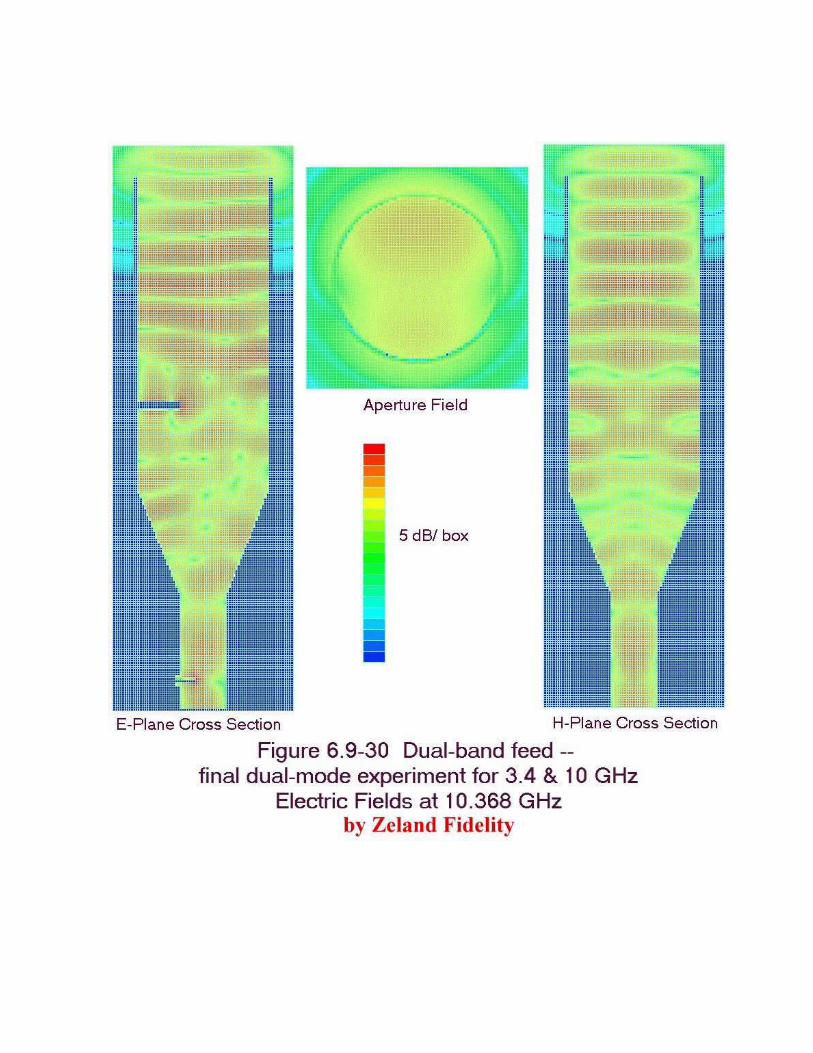
Now we can see that we must find a set of dimensions so that any modes that are excited arrive at theaperture with magnitudes and phases that provide a reasonable radiation pattern. I returned to thefirst experimental feed and tried some modifications. First, a longer large-diameter section toimprove 10 GHz phasing showed no significant improvement. Next, I changed the 10 GHz backsection to a cylindrical waveguide and added a flared transition section to make it a dual-mode feed at10 GHz — this one showed some improvement, but higher-order modes were still propagating anddistorting the pattern. Finally, I reduced the diameter of the large section to 0.68λ at 3456 MHz, assmall as I felt would provide a good pattern at that band, and then used HDL_ANT to calculate thebest flare dimensions for dual-mode operation at 10 GHz. The final combination works better — thefields at 10.368 GHz in Figure 6.9-30 show that the some undesired modes are excited by the flarebut cannot propagate in the reduced diameter of the larger section; note how the fields become wellbehaved near the aperture. The resulting field at the aperture is reasonably good, but the aperturediameter is quite large in wavelengths, so that the 10 GHz radiation pattern in Figure 6.9-31 is rathernarrow, and best f/D is about 0.8. The dual-band performance is still unsatisfactory, since theradiation pattern at 3456 MHz in Figure 6.9-32 is broad like a coffee-can feed, with best calculatedefficiency at an f/D of about 0.4. No good compromise for f/D seems likely, due to the difference inpatterns at the two frequencies.

The lesson we might learn from these dual-band feed experiments is that designing a good dual-bandfeedhorn is difficult and requires a lot of time, either experimental or computer time. W5LUA andW5ZN should be commended for their efforts.

Dualband 3 & 10 GHz feed with flare at 10.368 GHz,
Figure 6.9-31by Zeland Fidelity
Dish diameter = 30 λ Feed diameter = 2.04 λ
E-plane
H-plane
0 dB -10 -20 -30
Fee
d R
adia
tio
n P
atte
rn
W1GHZ 1998
0 10 20 30 40 50 60 70 80 90-90
-67.5
-45
-22.5
0
22.5
45
67.5
90
Rotation Angle aroundF
eed
Ph
ase
An
gle
E-plane
H-plane
specifiedPhase Center = 0.3 λ inside aperture
0.3 0.4 0.5 0.6 0.7 0.8 0.90.25
10
20
30
40
50
60
70
80
90
1 dB
2 dB
3 dB
4 dB
5 dB
6 dB
7 dB8 dB
MAX Possible Efficiency with Phase error
REAL WORLD at least 15% lower
MAX Efficiency without phase error
Illumination Spillover
AFTER LOSSES:
Feed Blockage
Parabolic Dish f/D
Par
abo
lic D
ish
Eff
icie
ncy
%

Dualband 3 & 10 GHz feedhorn with flare at 3456 MHz,
Figure 6.9-32by Zeland Fidelity
Dish diameter = 10 λ Feed diameter = 0.68 λ
E-plane
H-plane
0 dB -10 -20 -30
Fee
d R
adia
tio
n P
atte
rn
W1GHZ 1998
0 10 20 30 40 50 60 70 80 90-90
-67.5
-45
-22.5
0
22.5
45
67.5
90
Rotation Angle aroundF
eed
Ph
ase
An
gle
E-plane
H-plane
specifiedPhase Center = 0.1 λ inside aperture
0.3 0.4 0.5 0.6 0.7 0.8 0.90.25
10
20
30
40
50
60
70
80
90
1 dB
2 dB
3 dB
4 dB
5 dB
6 dB
7 dB8 dB
MAX Possible Efficiency with Phase error
REAL WORLD at least 15% lower
MAX Efficiency without phase error
Illumination Spillover
AFTER LOSSES:
Feed Blockage
Parabolic Dish f/D
Par
abo
lic D
ish
Eff
icie
ncy
%

6.9.7 Broadband feeds
There are two common types of broadband microwave antennas, log-periodic arrays and ridged-waveguide horns. For both, broadband means having some nominal gain and input match over arange of frequency; it does not necessarily mean have a well-controlled radiation pattern at everyfrequency in that range.
The log-periodic antenna is a travelling-wave antenna with tapered element lengths, so that a few ofthe elements are active at each frequency. Antenna handbooks14 often describe a microwave versionwith the elements cut in a flat plate, rather than individual rods, called a “trapezoidal-tooth” log-periodic. W2IMU once told me that log-periodic arrays have poor phase-center characteristics, andI’ve never seen anything to contradict him.
WA1MBA investigated log-periodicarrays as feed antennas15 and built some ofthe trapeziodal-tooth variety to cover thebands from 2304 to 10 GHz. Figure 6.9-33 is a photograph of one. When wemade gain measurements on a dish withthis feed, efficiency at 10 GHz was poor,under 40%.
Ridged-waveguide horns are rectangularor conical horns flared from waveguide ofthe same cross section. The ridges areadded to waveguide to increase the cutofffrequency for higher-order modes, thusincreasing the usable bandwidth of thedominant mode. If ridges are extendedinto the flare, the horn may have the sameusable bandwidth as the waveguide.
I have seen surplus conical horns with four ridges, every 90° around the perimeter, labeled “2 to 18GHz.” A feedhorn using this type of construction claimed16 to have an octave bandwidth and toprovide a constant secondary (dish) beamwidth over the bandwidth — but dish beamwidth shoulddecrease with increasing frequency if the performance is good. Radiation patterns were only pub-lished for the ends of the octave but had much different beamwidths, suggesting that the feed under-illuminated the reflector at the upper end of the band.
Rectangular ridged-waveguide horns can also provide very wide bandwidths. One paper17 describedversions covering 1 to 12 GHz and 0.2 to 20 GHz with nominal 12 dB gain. However, samplepatterns at several frequencies were very inconsistent, suggesting that this would not be a goodbroadband feedhorn.

The Antenna Engineering Handbook14 recommends a “planar sinous antenna” as a feed, claiming itprovides a constant beamwidth in the E- and H-planes and a frequency independent phase center.Unfortunately, only a sketch is given, with few details and no performance results. I have not foundany other references for this antenna.
Although these broadband antennas may not have useful radiation patterns over the whole bandwidth,there are probably smaller frequency ranges where the pattern is acceptable. Someone with a lot ofexcess time on a powerful computer could probably find dimensions to put the better patterns in themicrowave ham bands. Since the broadband antennas typically have moderate gain, 10 dB or so, thebeamwidth is more suitable for a higher f/D. Thus, an offset dish might be a better target for broad-band feed design.
6.9.8 Multi-band feed assemblies
An alternative to a multi-band feed is to have multiple feeds on one parabolic reflector.A good example of this technique is used by VE1ALQ18 for EME operation on 432 and 1296 MHz.The feed is shown in the photograph of Figure 6.9-34 — a combination of an EIA dual-dipole feed(Section 6.2.2) for 432 MHz and an N7ART diagonal feed (Section 6.5.3) for 1296 MHz. Thephysically-small diagonal feed in the center should have little effect at 432, while the two dipoles areso widely spaced that they are hardly in the pattern of the 1296 MHz feed. One feature of this combi-nation is that the dimensions of each feed can be adjusted for best illumination over a range of f/D,and the phase center of each feed can be individually located at the focus of the dish.

The VE1ALQ feed above is a good example, but it would be difficult to have more than two bandswith a common phase center. Perhaps a dual-band feed could be used at the center, for a total ofthree bands.
On a large dish, several feeds could be mounted side-by-side, requiring rotation of the dish whenchanging bands to compensate for the off-axis feed. The best focal distance for an off-axis feed is ona curve called a “Petzval surface19.” A combination of dual-band feeds could add up to a good multi-band antenna, but the operational difficulty of dish movement when changing bands is problematic,particularly with very weak signals (the interesting ones!).
A better alternative might be movable feeds, with a mechanism to move the desired feed into position.Large radiotelescopes often have movable feed arrangements, but they are large enough to tolerate asmall room full of equipment behind the feed with little blockage. Most amateurs must get by withmuch smaller dishes, so a good alternative is the offset-fed dish, where the feed mechanism andunused feeds can be positioned out of the beam.
One such feed mechanism,by WD4MUO20, is shownin the photograph ofFigure 6.9-35, althoughJohn’s example hasfeedhorns more suitablefor a prime-focus dish.Several waveguides fordifferent bands feed intothe lower plate. Theupper plate moves thedesired horn into position,with a waveguide bendconnecting from the hornto the proper location onthe upper plate to matchthe feed waveguide.Obviously, some carefulmachining is required foreverything to line up properly.
A somewhat simpler approach is used by KA1ZE on his latest “rovermobile.” The feeds are rotatedinto position by a standard antenna rotor, which has enough power to rotate both the feeds and atransverter for each band. Figure 6.9-36 shows the assembly; the rotor and all the equipment are outof the beam of the offset dish. One problem that Stan found was that the obliquely-mounted rotorhad too much slop to reliably position the feedhorns at the dish focus — rotors are designed forvertical mounting. He added the plastic bearing above the feeds to remove the slop.

A final choice, where the dish is accessible, is to make the feeds easily interchangeable. WA5VJB hassuch a mechanism on his EME dish, fashioned from plastic plumbing fixtures. On EME, there isusually adequate time between schedules for a quick feed change.
6.9.9 Summary
Multi-band feeds are never as good as the best single-band feeds, but some two-band feeds canprovide performance that is acceptably close. For many amateur installations, having an additionalband without requiring an extra dish is a good compromise. Another useful feature is he ability toaim the dish on a lower band, then switch to a higher band without disturbing the dish. However, forEME, where every dB is essential, co-located feeds or interchangeable feeds might be a better choice.

6.9 References
1. J. Harrison, W5ZN, “Horns for the Holidays,” Proceedings of Microwave Update ’97, ARRL,1997, pp. 147-149.
2. J. Harrison, W5ZN, “W5ZN Dual Band 10 GHz / 24 GHz Feedhorn,” Proceedings ofMicrowave Update ’98, ARRL, 1998, pp. 189-190.
3. J. Harrison, W5ZN, “Further Evaluation of the W5LUA & W5ZN Dual Band Feeds,”Proceedings of Microwave Update ’99, ARRL, 1999, pp. 66-84.
4. T. Hill, WA3RMX, “A Triband Microwave Dish Feed,” QST, Aug. 1990, pp. 23-27.
5. Zeland Software, Inc. http://www.zeland.com
6. K. Britain, WA5VJB, “Dual Band Dish Feeds,” Proceedings of Microwave Update ’91, ARRL,1991, pp. 174-175.
7. G.J.Burke & A.J. Poggio, Numerical Electromagnetic Code (NEC) — Method of Moments,Lawrence Livermore Laboratory, 1981.
8. P. Wade, N1BWT, “Dual-band Feedhorn for the DSS Offset Dish, Proceedings of the 23rd
Eastern VHF/UHF Conference, ARRL, 1997, pp. 107-110.
9. D. Evans, G3RPE, “Pyramidal horn feeds for paraboloidal dishes,” Radio Communications,March 1975. also in:
10. M.W. Dixon, G3PFR, Microwave Handbook, Volume 3, RSGB, 1992, p. 18.85.
11. A. Ward, WB5LUA, “Dual Band Feedhorns for 2304/3456 MHz and 5760/10368 MHz,Proceedings of Microwave Update ’97, ARRL, 1997 pp. 158-163.
12. W.A. Imbriale, P.G. Ingerson, and W.C. Wong, “Experimental Verification of the Analysis ofUmbrella Parabolic Reflectors,” IEEE Transactions on Antennas and Propagation, September1973, pp. 705-708.
13. http://www.ntms.org/FeedPatterns.htm
14. R.H. DuHamel & J.P. Scherer, “Frequency-Independent Antennas,” in R.C. Johnson, AntennaEngineering Handbook, McGraw-Hill, 1993, pp. 14-33 to 14-65.
15. T. Williams, WA1MBA, “A Broadband Dish Feed for Amateur Radio SHF,” Proceedings ofMicrowave Update ’94, ARRL, 1994, pp. 23-33.
16. J.K. Shimizu, “Octave bandwidth feed horn for paraboloid,” IRE Transactions on Antennas andPropagation, March 1961, pp. 223-224.

17. J.L. Kerr, “Short Axial Length Broad-Band Horns,” IEEE Transactions on Antennas andPropagation, September 1973, pp. 710-714.
18. http://www.ve1alq.bizland.com/downloads/index.htm
19. C. Scott, Modern Methods of Reflector Antenna Analysis and Design, Artech House, 1990,pp. 70-73.
20. J.E. Anderson, WD4MUO/0, “Switched Feeds for Multi-band Parabolic Antennas,” Proceedingsof Microwave Update ’99, ARRL, 1999, pp. 100-106.