7 development drilling and completions production operations to meet the depletion plan ... subject...
TRANSCRIPT

White Rose DA Volume 2 (Development Plan) • January 2001 Page 239
7 DEVELOPMENT DRILLING AND COMPLETIONS
The White Rose oilfield was discovered in 1988 with the drilling of the E-09 well. Since that time, fouradditional delineation wells were drilled into the White Rose structure. They are L-08, A-17, N-30, andH-20. The first three of these wells were suspended. H-20 was abandoned. However, since they did notinclude options for iceberg protection, at present there are no plans for them to be used in thedevelopment of the White Rose oilfield.
7.1 Development Drilling
The project base case currently identifies the need for 15 wells, however, there is potential for up to 25wells required to develop the South Avalon reservoir, of which 10 to 14 will be producing wells, six toeight will be water injection wells, and two to three will be gas injection wells.
Initially, up to 10 wells will be drilled before field production will commence. Plans call for the wells tobe drilled in clusters or through templates located in glory holes. Semi-submersible MODUs will be usedto drill and complete these wells before the arrival of the FPSO. The remainder will be drilled in parallelwith production operations to meet the depletion plan objectives.
7.1.1 Tentative Drilling Schedule
The current plan is to start drilling 24 months prior to First Oil. Subject to ongoing petroleumengineering studies, it is anticipated that up to 10 producing and injection wells will have been drilled andcompleted before the arrival of the FPSO. Details on the drilling sequence are provided in Table 7.1-1.
Water injection wells, which are the deepest, are drilled first to capture as much information about theblock as possible before the producers are drilled. Their trajectory/location is not as critical as would bethe case for production wells.
7.1.2 Drilling Hazards
There were no significant operational problems encountered during the drilling of the White Rosedelineation wells. However, typical potential problems that may be encountered during developmentdrilling, and which will be addressed within the well design and contingency planning, are discussedbelow.

White Rose DA Volume 2 (Development Plan) • January 2001 Page 240
Table 7.1-1 Drilling Sequence Details
No. Well Name Comments123456789101112131415
B14W1B7W1Gas #1B7P1B3W1B14P1B7P2B3P2B3P1B1W1Gas #2B1P2B6W1B1P1B6P1
Information to locate Block 14 producer (w/pilot)Information to locate Block 7 producerTime used to locate Block 7 and 14 producersNo. 1 producerInformation to locate Block 3 producerNo. 2 producerNo. 3 producerNo. 4 producerNo. 5 producer – “First Oil”Information to locate Block 1 producers (w/pilot)Second gas injectorNo. 6 producerInformation to locate Block 6 producerNo. 7 producerNo. 8 producer
7.1.2.1 Shallow Gas
Although there has been no occurrence of shallow gas in any of the wells drilled so far in the White Rosefield, indications of gas chimneys and seismic anomalies have been identified on some site surveys in thefield. A shallow gas accumulation could cause uncontrolled well flow if encountered prior to setting thesurface casing and installing the blow out preventer (BOP) stack. The only concern raised by the 1997shallow 3-D reprocessed data is the presence of a gas chimney centred on the crest of the White RoseDiapir that extends in a small area toward southwest. No delineation or development drilling is plannedat this time on or near this area affected by gas contamination of low porosity sediments.
Husky Oil has shallow gas preparedness and drilling procedures in its East Coast drilling policydocument. The policy includes drilling riserless prior to running the stack and conducting winch-offdrills prior to spudding. This policy will be reviewed for development drilling, addressing issues such asthe cuttings conveyance system.
7.1.2.2 Hole Instability
Borehole shear failures occur in planes that contain the minimum and maximum principal stresses (thatis, perpendicular to the intermediate stress). The different types of borehole failures that occur inisotropic and anisotropic rock can manifest as a result of mud weight and insitu stresses. The failuremode shifts as the intermediate stress shifts between the axial, tangential, and radial directions.

White Rose DA Volume 2 (Development Plan) • January 2001 Page 241
On high angle development wells, the shales will be exposed to drilling for longer periods of time andhole instability could be accentuated. Hole cleaning issues could become significant if hole instabilityincreases.
Hole instability on White Rose is currently not considered a high drilling risk. To date, the onlyindications of potential stability problems occurred in the 311-mm hole section, with hole fill seentowards the total depth (TD) of the section. This phenomenon could be an indicator of a stressedformation and could have a more pronounced impact if the section was inclined.
The mud type and properties, the casing seat selection and any pilot hole design would all be impacted bythe presence and mitigation of hole instability problems.
Proposals have been requested for a study into well bore stability at White Rose. The initial part of thestudy was to determine, using data obtained to date, the potential for instability in the White Roseformations and, if required, to provide recommendations on any additional data that could be collected inthe 2000 Delineation Drilling Program.
7.1.2.3 Formation Pressure
Neither abnormal pressure nor lost circulation have been apparent in the White Rose wells. Porepressures in the Avalon sands are between 29 and 30 MPa, depending on depth. The sands have a normalpressure gradient of 10.1 kPa/m.
7.1.2.4 Well Control
Industry-accepted drilling practices will be followed in order to minimize the risk of well controlincidents or kicks. This includes such activities as continuous monitoring of drilling mud weight whiledrilling, hole monitoring, carefully designed casing programs and frequent BOP tests.
7.1.2.5 Differential Sticking
Differential sticking across any permeable zones may occur in high-angle wells. Tight control of drillingfluid properties, the use of synthetic-based fluid, and good tripping practices will be applied so as tominimize this problem.

White Rose DA Volume 2 (Development Plan) • January 2001 Page 242
7.1.3 Basis of Well Design
This section presents the basis of well design for the White Rose development wells. The basis of designtakes into account experience from previous wells and the functional requirements for the developmentwells. Well design will evolve over the pre-production project phases, and subsequently over the life ofthe field, in order to take advantage of equipment development, new techniques and drilling experience.
7.1.3.1 Casing and Hole Sizes
The casing geometry will dictate the conduit size and setting depths. Once the casing has been set theflexibility of the operations are limited. The areas considered in developing the basis of casing designwere:
• Completion Design: The tubing size, completion components, metallurgical requirements, and thetree configuration all impact on the casing design.
• Well Trajectory: The shape of the well bore will influence casing wear and connection types.
• Casing Seat: The two main critical casing seats are the surface casing and production casingpoints. The surface casing seat determines the available kick tolerance for theremainder of the well. Under the current design case, the 900-m TVD BRTdepth provides enough kick tolerance to reach the well TD. The productioncasing seat selection could be critical for gas shut-off if the casing point iswithin the reservoir section. This will be further influenced by the verticaldepth control and any pilot hole requirements.
• Contingency: The requirement to carry a casing string contingency will impact the casingdesign. Issues which influence this design feature are the minimum acceptablehole size through the reservoir, areas of identified drilling risks, pilot holerequirements, batch drilling and the need to have flexibility in the directionalprofile, formation evaluation, drilling performance, long lead times, andmaterial stocks.
Wells will have an average horizontal departure of 4,000 m and a horizontal section through the reservoir
of between 2,000 to 2,500 m. Well profiles have a preliminary maximum design build rate of 3°/30 m.

White Rose DA Volume 2 (Development Plan) • January 2001 Page 243
A 914-mm conductor hole will be drilled to approximately 250 m below the rotary table on the drillingrig and a 762-mm conductor casing will be run and cemented to seafloor. A 406-mm hole is thenplanned to approximately 800 to 900-m below rotary table. The 340-mm surface casing will be cementedto the sea floor.
The 311-mm main hole will then be drilled to either the top of the Avalon Formation or possibly to somedeeper depth in high-angle or horizontal wells. The production casing will be set at this point. The depthin high-angle wells will depend upon sealing off the gas cap in the reservoir.
The upper section of the 244-mm production casing may have to be increased in diameter toaccommodate the surface controlled subsurface safety valve (SCSSV).
A 216-mm hole will be drilled to TD and either a 178 or 140 mm liner will be run (cemented oruncemented). The well may also be completed open hole. Additional well completion details arediscussed in Section 7.2, including an illustration of the well casing profiles for a 140 mm tubing string.
Drilling Fluid Program
The mechanism of formation damage in the reservoir will be one of the main drivers of the drilling andcompletion fluid design.
The drilling fluids used will be optimized to reduce fluid loss, to control rheology, and maintain holestability. The drilling fluid program will be similar to that used on the past delineation wells. Seawaterwith prehydrated gel muds or polymer muds are planned for the top intervals of the well to the surfacecasing setting depth.
A water or synthetic-based system will be used for the intermediate hole, depending on the well profile.The intention would be to use water-based mud (WBM) systems in this hole section as long as the wellbore stability and drag are acceptable. Synthetic-based muds (SBMs) are the most reliable method ofmanaging hole stability and they also provide lubricity to lower drilling string torque and drag.
One of the objectives of the ongoing core and fluids studies is to identify the most likely damagemechanism(s) for the Avalon Formation. Once the mechanism(s) has been isolated, mud formulationswill be tested to ensure that the fluid selected has minimal damaging characteristics or that any damagecan be easily cleaned up and treated.

White Rose DA Volume 2 (Development Plan) • January 2001 Page 244
The mud system will also have to be tested and evaluated on the other design aspects. There will be aneed to balance the fluid design against all the well design requirements.
Cementing Program
The cementing program will be similar to that used on past delineation wells. Conductor and surfacecasings will be cemented to the seafloor. The production casing will be cemented high enough to preventfuture casing instability and to isolate permeable zones. To ensure a leak-off path for trapped fluidexpansion during production, production casing will not be cemented into the previous shoe.
Well Control System
The selection of the BOP equipment will be part of the MODU bid evaluation. Typically, a 476-mm, 69to 103 MPa BOP equipped with four rams (including shear rams) and an annular preventer will beinstalled on a 476-mm wellhead run with the surface casing, and used for the remainder of the well. TheBOP system typically has capacity to exceed the known pressure in the White Rose field by a factor oftwo. This approach is taken to be able to address any unexpected pressure which could occur.
7.1.3.2 Wellhead Design
The selection of a subsea wellhead system is still ongoing. The choice of either template or clusteredwells is not finalized. Subsea well protection for template and cluster wells will be by dredged gloryholes. On satellite wells, drilled glory holes and caisson systems are being considered.
Directional Drilling
Plans call for drilling in clusters of approximately six wells. Wells will have an average horizontaldeparture of 4,000 m and a horizontal section through the reservoir of between 2,000 to 2,500 m. Wellprofiles have a preliminary maximum design build rate of 3°/30 m. Horizontal wells are beingconsidered in the pay zone to provide increased productivity. Kick-off elevation and well profiles will becustomized for each well.
On the main hole of the directional wells, mud pulse telemetry directional tools will be used. The surveyintervals and the type of surveying system used will be sufficient to assure accurate entry into the targetand avoid collision with adjacent wells, and will provide adequate wellbore positioning information toreliably target a relief well, if required.

White Rose DA Volume 2 (Development Plan) • January 2001 Page 245
7.2 Well Completions
The White Rose development well completions will be designed to maximize well productivity whilemaintaining necessary standards of risk and well integrity.
7.2.1 Production Wells
Current reservoir depletion studies indicate that horizontal wells will provide the best exploitationalternative for White Rose. It is anticipated that up to 15 to 25 new drill production and injection wells,located in up to four drill centres, will be required for the White Rose oilfield development. Thesuspended discovery well E-09 and 1999 delineation wells A-17, L-08, N-30 and H-20 are not beingconsidered for completion as production or injection wells at this time.
7.2.1.1 Completion Configuration and Tubing Size
Tubing size requirements are a function of a well’s production or injection capacity. Considerations ofthe well requirements over the life of the field can determine whether monobore or conventionalcompletions are best used. Conventional completions have production casing (liner) across the zone ofinterest with a production packer and smaller internal diameter (ID) tubing to surface. A conventionalcompletion which may be applied in oil wells that require only 140 mm tubing with a 178 mm liner isillustrated in Figure 7.2-1.
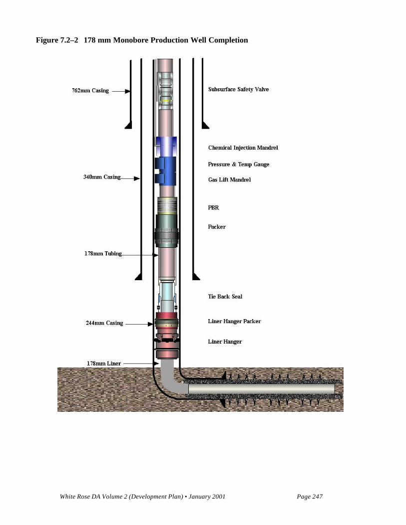
Monobore completions have tubulars, downhole equipment and tree components with a similar ID toallow full wellbore access to larger diameter wellbore equipment. The production casing is landed abovethe formation of interest with a tie back liner over the completed zone as shown in Figure 7.2-2. Thistype of completion may be employed where a 178-mm flow path is required to facilitate higherproduction or injection rates where friction pressure loss from high velocity fluids is a concern.
7.2.1.2 Wellbore Isolation Measures
SCSSVs will be used to prevent flow of formation fluids to surface in the event of a wellhead failure.The White Rose development wells will have tubing-retrievable SCSSVs, which are an integral part ofthe completion tubing string and allow for larger diameter tool access into the bottom of the wellbore.The tubing-retrievable SCSSVs will also be designed to permit the insertion of wireline-retrievable insertSCSSVs to provide a means of maintaining isolation barriers without pulling the tubing string.

White Rose DA Volume 2 (Development Plan) • January 2001 Page 246
Figure 7.2–1 140 mm Conventional Production Well Completion
White Rose DA Volume 2 (Development Plan) • January 2001 Page 247
Figure 7.2–2 178 mm Monobore Production Well Completion

White Rose DA Volume 2 (Development Plan) • January 2001 Page 248
Completions will be designed to have two independent annular barriers between the formation and theseafloor. The well tubulars, SCSSVs and production packer located just above the completed zone is theprimary annular barrier system separating the formation from the annulus. The hydraulically operatedannular master valve on the subsea tree functions as the second annular barrier by automatically closingif there is a loss of control line hydraulic pressure to the valve.
7.2.1.3 Well Production Performance
Well performance modelling based on the reservoir properties of the discovery and delineation wells hasbeen conducted for both flowing and artificial lift (gas lift) scenarios. The flowing well model suggeststhat initial oil rates of between 2,800 and 4,200 m³/d are possible from horizontal productiondevelopment wells completed with 140-mm tubing. A well with average reservoir properties should flowat 3,600 m³/d oil prior to water or gas breakthrough. The flowing well performance at various water cutswith the two inflow performance lines illustrating the range of productivity expected is shown in Figure7.2-3 for a 2,000 m horizontal production well.
7.2.1.4 Artificial Lift
Water associated with White Rose oil production is expected to increase over the project life of thedevelopment. The flow modelling referred to above indicates that oil wells will require artificial liftwhen water cut exceeds 40 percent. Gas lift will be a readily available means of artificial lift, with gascompression facilities required for the reinjection of produced gas. Gas lift also has the advantage overother means of artificial lift due to its high reliability and efficiency. This is critical for subsea wellswhere reliability and efficiency are important for effective operation. To avoid the high cost of workingover wells later in their producing life, gas lift side pocket mandrels will be included in the initialcompletion design for oil wells. This ability to control flow from the initial completion will enablegreater flexibility in reservoir depletion management. The effect of gas lift on a well producing at 80percent water cut is illustrated in Figure 7.2-4. As shown in Figure 7.2-4, high water cut wells withsuperior reservoir properties are still capable of up to 2,500 m³/d liquid (500 m³/d oil) at an injection gasrate of 400 10³m³/day.

White Rose DA Volume 2 (Development Plan) • January 2001 Page 249
Figure 7.2–3 Flowing Well Performance Curve – 2,000 m Horizontal Well, 140 mm Tubing
0
5000
10000
15000
20000
25000
30000
35000
40000
45000
0 1000 2000 3000 4000 5000 6000
Liquid Rate (m3/day)
Flo
win
g B
ott
om
ho
le P
ress
ure
(kP
a) 60% Watercut
0% Watercut
20% Watercut
40% Watercut
Horizontal Well IPR: Perm = 90 md, Skin = 0
Horizontal Well IPR: Perm = 60 md, Skin = 10

White Rose DA Volume 2 (Development Plan) • January 2001 Page 250
Figure 7.2–4 Gas Lift Well Performance 140 mm, 80% Water Cut, 2,000 m Horizontal Well
0
5000
10000
15000
20000
25000
30000
35000
40000
45000
0 500 1000 1500 2000 2500 3000 3500 4000 4500 5000
Liquid Rate (m3/day)
Flo
win
g B
ott
om
ho
le P
ress
ure
(kP
a)
Gas Lift Rate = 0 m3/day
GLR = 400 x 103m3/day
GLR = 200 x 103
m3/day
Hz Well IPR: Perm =90, Skin = 0
Hz Well IPR: Perm =60, Skin =10
GLR = 600 x 103
m3/day

White Rose DA Volume 2 (Development Plan) • January 2001 Page 251
7.2.1.5 Completion Program
Prior to the start of production, all wells in a given glory hole will likely be batch completed after beingdrilled and temporarily suspended. White Rose development wells prior to First Oil will be batchcompleted to take advantage of operational efficiencies. A simplified summary of the operationsinvolved in a typical completion is outlined below for a 140-mm monobore completion. At the end ofbatch drilling operations, the wells will be left with appropriate barriers in place.
1. Inspect wellhead and retrieve external debris cover.2. Run in drilling BOP and riser. Connect to subsea tree.3. Pressure test BOP and subsea tree.4. Pull wellhead plug and bridge plug.5. Clean out to liner top. Clean out to bottom of liner.6. Run casing scrapers over 244-mm casing and 140-mm liner.7. Circulate well to clear brine to remove drilling fluid and cement cuttings.8. Run permanent production packer on work string.9. Circulate annulus to packer fluid prior to setting packer hydraulically.10. Run in 140-mm tubing, complete with packer seal assembly, expansion assembly, gas lift side-pocket
mandrels, permanent downhole gauges, tubing-retrievable SCSSVs and control line.11. Stab into polish bore receptacle and land tubing hanger.12. Pressure test packer and SCSSV.13. Perforate with coil tubing-conveyed guns.14. Flow well for a short clean up and snub out guns.15. Clean up and test well.16. Displace drilling riser to water.17. Remove drilling BOP and riser.18. Install debris cover.
7.2.1.6 Tubing Materials and Accessories
White Rose reservoir fluids sampled to date have indicated CO2 levels of between 1 and 2 mole percentand H2S levels of up to 12 ppm. National Association of Corrosion Engineers (NACE) requirements forusing materials that are resistant to erosion and corrosion will form the basis for production equipmentspecifications. Tubulars will be designed with consideration of life of field conditions.

White Rose DA Volume 2 (Development Plan) • January 2001 Page 252
7.2.1.7 Production Trees
Production trees will be located in open glory holes for iceberg scour protection. Installation will bethrough the moonpool of the drilling and completion MODU. As with all subsea facilities, productiontrees will be selected to provide diverless installation, operation, inspection and maintenance. The treeswill be either vertical or horizontal types capable of installation on the 476 mm wellheads. The subseatree schematics in Figures 7.2-5 and 7.2-6 illustrate the tree valve and equipment components for atypical production well. Vertical subsea trees have valves located in line vertically over the production orinjection bores (Figure 7.2-5). Horizontal trees have tubing hanger plugs as vertical barriers and themaster valves are located on the side outlets (Figure 7.2-6).
Provisions for gas lift and chemical injection complete with remotely operated barrier valves will beincorporated into the tree design. The production trees will also have a data cable path for the permanentdownhole gauges. Subsea tree controls will also enable lock out from the FPSO during workoveroperations to prevent accidental operation of equipment when the workover vessel is connected to thewellhead.
The production subsea tree equipment will be rated to at least 34.5 MPa based on a maximum expectedpressure at surface of 23.1 MPa. The maximum surface pressure was calculated from the originalreservoir pressure with gas filled tubing.
7.2.1.8 Perforating
Alternatives of open hole, slotted liner or cemented liner completions are being studied to determine themethod most suitable for the White Rose development. Where a cemented production liner is used theselection of a perforating system will be based on criteria that will deliver the optimal productivity withinacceptable risk levels.
The most likely perforating system will be tubing conveyed perforating (TCP) type, deployed on eithercoiled tubing or a work string. The coiled tubing system enables perforating underbalanced and snubbingthe guns without killing the well. The work string system allows longer intervals to be perforated in oneoperation but may require killing the well prior to removal of the guns. Perforating interval selection willbe designed to minimize the potential for water and gas coning.

White Rose DA Volume 2 (Development Plan) • January 2001 Page 253
Figure 7.2–5 Vertical Subsea Tree
P
P/T
Primary Valve
Secondary Valve
P/T GaugeP/T
Seal
Packer/Liner Top PBR
Injection Mandrel
Electrical Line
Check Valve
Hydraulic Line
Lockdown
1 F
Chemical Injection Upper (production wellsonly)Surface Controlled Subsurface SafetyValve
Chemical Injection Lower (production wells only)
Down Hole Pressure
Temperature GaugeGas Lift Mandrel (gas lift wells only)

White Rose DA Volume 2 (Development Plan) • January 2001 Page 254
Figure 7.2–6 Horizontal Subsea Tree
3 F
Chemical Injection Upper (production wells only)
Surface Controlled Subsea
Chemical Injection Upper (production well only)
Down Hole Pressure Temperature Gauge
Gas Lift Mandrel (gas lift wells only)
2 F
Internal TreeCap
P
P/T
Hanger Plug
Packer/Liner Top
Electrical Line
InjectionMandrel
Check Valve
P/T Gauge
Lockdown
P/T
Seal
PrimaryValve
Hydraulic Line
SecondaryValve
Chemical Injection Upper (production wellsonly)
Surface Controlled
Chemical Injection Upper (production wellonly)Down Hole Pressure Temperature Gauge
Gas Lift Mandrel (gas lift wellsonly)

White Rose DA Volume 2 (Development Plan) • January 2001 Page 255
7.2.1.9 Packers and Accessories
To ensure the completions can adequately accommodate all thermal and load forces, permanenthydraulically set production packers will be run. The production packers use polished bore receptaclesand seal assemblies to control pipe stress and facilitate workovers. Any monobore completions can alsohave hydraulically set liner top packers.
7.2.1.10 Completion Fluids
Separate completion fluids will be used for cleaning out the well after drilling, providing a benignenvironment in the packer annulus and for perforation operations. The well is cleaned out at the start ofcompletion operations to ensure clean casing surfaces for packer seals and to remove any debris whichcould impair production equipment operations. This fluid will be seawater-based and facilitatescirculating up cement cuttings and contamination remaining after the liner cement job. Viscous polymergelled fluid pills may be required to sweep the hole clean to total depth, especially over the horizontalsections.
Corrosion-inhibited and oxygen-scavenged fluid is circulated into the annulus between the completiontubing and production casing above the production packer to prevent corrosion of the completionequipment.
The perforating fluid provides a predetermined measure of hydrostatic head which controls the initialdirection of flow after perforating. Work is ongoing to determine whether an overbalanced orunderbalanced perforating system will be used for White Rose development wells. If an underbalancedsystem is used where flow is into the wellbore, then either a nitrogen cushion or an oil-based fluid will beused. An overbalance system will likely employ a clean brine fluid. The perforating fluid will also bedesigned to prevent any adverse fluid interaction with the formation.
7.2.1.11 Sand Control
Current reservoir rock material strengths data indicate that sand production should not be a problem.However, any well completion programs will be designed to mitigate sand production.

White Rose DA Volume 2 (Development Plan) • January 2001 Page 256
7.2.2 Injection Wells
7.2.2.1 Well Designs
Current water injection well design is for continuous injection of 2,000 to 6,000 m³/day of seawater perwell, with a maximum of up to 9,000 m³/day. To ensure adequate capacity, it is likely the water injectionwells will be horizontal, with 178-mm monobore completion or 140-mm conventional completion. Asmentioned previously, gas injection wells are required to facilitate conservation and possibly aid reservoirpressure maintenance. The gas injection wells will be designed for continuous injection of 1,000 to 3,00010³m³/d gas per well, with a maximum of up to 4,000 10³m³/day gas.
Water injection and gas injection well performance plots for typical development conditions areillustrated in Figures 7.2-7 and 7.2-8.
7.2.2.2 Injection Christmas Trees
For project equipment synergy and to simplify completions and workovers, injection trees will likely besimilar in specifications and design to the production trees. Gas injection trees may be required to berated to 69 MPa.
7.2.2.3 Tubing and Connections
Studies are ongoing to determine appropriate materials and connection type for injection well tubing.Efforts will be made to design injection fluid processing such that downhole equipment can be asstandard as possible. The tubulars will be designed with consideration of life of field conditions.
7.2.2.4 Wellbore Isolation Measures
SCSSVs on injection wells will be similar in design and specification as production wells SCSSVs.
7.2.2.5 Liners and Packers
Injection packers serve to isolate the annulus from injection fluids and pressures. White Rose injectionpackers will be permanent design with polished bore receptacles to provide for thermal movement of thetubing. As an added precaution, corrosion resistant material will be used on exposed surfaces of theinjection packers.

White Rose DA Volume 2 (Development Plan) • January 2001 Page 257
Figure 7.2–7 Inflow vs Outflow for 2,000 m Horizontal Gas Injection Well
0
10000
20000
30000
40000
50000
60000
0 5000 10000 15000
Water Injection Rate (m3/day)
Bo
tto
mh
ole
Pre
ssu
re (k
Pa)
7" Tubing3.5" Tubing 4.5" Tubing 5.5" Tubing
Perm = 40, Skin = 10 Perm = 60, Skin = 0

White Rose DA Volume 2 (Development Plan) • January 2001 Page 258
Figure 7.2–8 Inflow vs Outflow for 500 m Horizontal Gas Injection Well
0
5000
10000
15000
20000
25000
30000
35000
40000
45000
50000
0 2000 4000 6000 8000 10000 12000
Gas Injection Rate (1000m3/day)
Bo
tto
mh
ole
Pre
ssu
re (k
Pa)
3.5" Tubing
7" Tubing
5.5" Tubing
4.5" Tubing
Perm = 60, Skin = 10
Perm = 90, Skin = 0

White Rose DA Volume 2 (Development Plan) • January 2001 Page 259
7.2.2.6 Completion Fluids
Unless perforating design differs from the producing wells, the completion fluids will be the same for theinjection wells.
7.3 Well Interventions
7.3.1 Major Workovers
Operations that involve replacing or removing items such as subsea trees, control lines, tubing, SCSSVs,and packers are considered major workovers. These types of workovers require mobilization of a semi-submersible drilling rig with a riser and BOP system for removal of the completion equipment. It is anobjective of the completion design to reduce the number of major workovers during life of fieldconditions for the well.
7.2.2 Minor Workovers
Wireline and coiled tubing operations are considered to be minor workovers. However, because the wellsare subsea, operations require mobilizing either a workover vessel or a semi-submersible drilling unit.
Statistics on subsea developments suggest that approximately one minor workover per well will berequired every four to seven years. Operations such as installing or removing plugs, gas lift valves,chemical injection valves and downhole gauges are considered to be minor workovers, as are otherinterventions that do not require removal of the completion string.