7 downspout draft 2016 - nashville, tennessee · general application activity: downspout...
TRANSCRIPT
General Application
Activity: Downspout Disconnection GIP‐07
Volume 5 – Green Infrastructure Practices February 2016 1
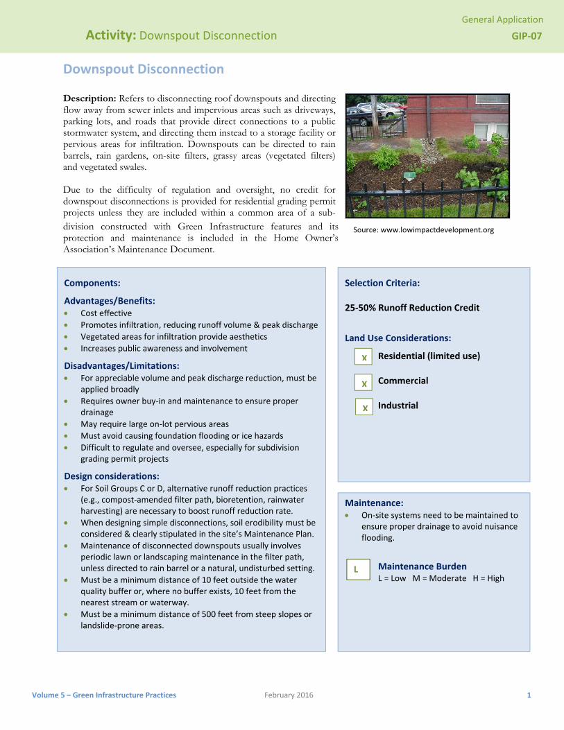
Downspout Disconnection Description: Refers to disconnecting roof downspouts and directing flow away from sewer inlets and impervious areas such as driveways, parking lots, and roads that provide direct connections to a public stormwater system, and directing them instead to a storage facility or pervious areas for infiltration. Downspouts can be directed to rain barrels, rain gardens, on-site filters, grassy areas (vegetated filters) and vegetated swales. Due to the difficulty of regulation and oversight, no credit for downspout disconnections is provided for residential grading permit projects unless they are included within a common area of a sub-division constructed with Green Infrastructure features and its protection and maintenance is included in the Home Owner’s Association’s Maintenance Document.
Components:
Advantages/Benefits: Cost effective
Promotes infiltration, reducing runoff volume & peak discharge
Vegetated areas for infiltration provide aesthetics
Increases public awareness and involvement
Disadvantages/Limitations: For appreciable volume and peak discharge reduction, must be
applied broadly
Requires owner buy‐in and maintenance to ensure proper drainage
May require large on‐lot pervious areas
Must avoid causing foundation flooding or ice hazards
Difficult to regulate and oversee, especially for subdivision grading permit projects
Design considerations: For Soil Groups C or D, alternative runoff reduction practices
(e.g., compost‐amended filter path, bioretention, rainwater harvesting) are necessary to boost runoff reduction rate.
When designing simple disconnections, soil erodibility must be considered & clearly stipulated in the site’s Maintenance Plan.
Maintenance of disconnected downspouts usually involves periodic lawn or landscaping maintenance in the filter path, unless directed to rain barrel or a natural, undisturbed setting.
Must be a minimum distance of 10 feet outside the water quality buffer or, where no buffer exists, 10 feet from the nearest stream or waterway.
Must be a minimum distance of 500 feet from steep slopes or landslide‐prone areas.
Selection Criteria: 25‐50% Runoff Reduction Credit
Land Use Considerations:
Residential (limited use) Commercial Industrial
Maintenance: On‐site systems need to be maintained to
ensure proper drainage to avoid nuisance flooding.
Maintenance Burden L = Low M = Moderate H = High
X
X
L
X
Source: www.lowimpactdevelopment.org
General Application
Activity: Downspout Disconnection GIP‐07
Volume 5 – Green Infrastructure Practices February 2016 2
SECTION 1: DESCRIPTION
This strategy involves managing runoff close to its source by intercepting, infiltrating, filtering, treating or reusing it as it moves from the impervious surface to the drainage system. Two kinds of disconnection are allowed: (1) simple disconnection, whereby rooftops and/or on-lot residential impervious surfaces are directed to pervious areas, and (2) disconnection leading to an alternative runoff reduction practice(s) adjacent to the roof (Figure 7.1). Alternative practices that take up less space can be used where space in not available for the disconnection practices described above. Applicable alternative runoff practices are shown in Table 7.1, below.
SECTION 2: PERFORMANCE
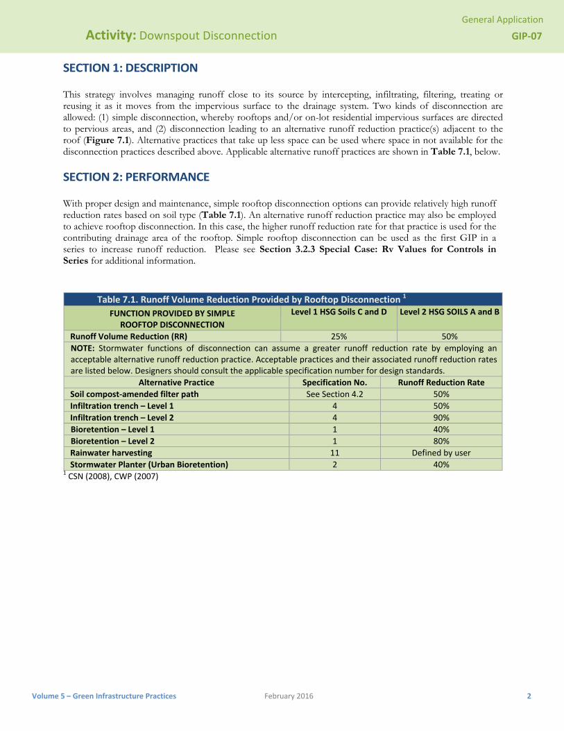
With proper design and maintenance, simple rooftop disconnection options can provide relatively high runoff reduction rates based on soil type (Table 7.1). An alternative runoff reduction practice may also be employed to achieve rooftop disconnection. In this case, the higher runoff reduction rate for that practice is used for the contributing drainage area of the rooftop. Simple rooftop disconnection can be used as the first GIP in a series to increase runoff reduction. Please see Section 3.2.3 Special Case: Rv Values for Controls in Series for additional information.
Table 7.1. Runoff Volume Reduction Provided by Rooftop Disconnection 1
FUNCTION PROVIDED BY SIMPLE ROOFTOP DISCONNECTION
Level 1 HSG Soils C and D Level 2 HSG SOILS A and B
Runoff Volume Reduction (RR) 25% 50%
NOTE: Stormwater functions of disconnection can assume a greater runoff reduction rate by employing an acceptable alternative runoff reduction practice. Acceptable practices and their associated runoff reduction rates are listed below. Designers should consult the applicable specification number for design standards.
Alternative Practice Specification No. Runoff Reduction Rate
Soil compost‐amended filter path See Section 4.2 50%
Infiltration trench – Level 1 4 50%
Infiltration trench – Level 2 4 90%
Bioretention – Level 1 1 40%
Bioretention – Level 2 1 80%
Rainwater harvesting 11 Defined by user
Stormwater Planter (Urban Bioretention) 2 40% 1 CSN (2008), CWP (2007)
Volum
Act
me 5 – Green Inf
SECTION
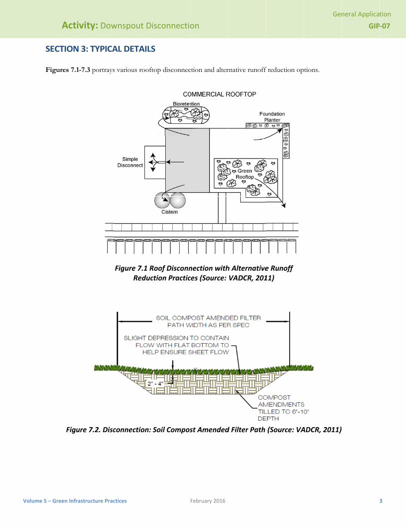
Figures 7.
Fig
tivity: Dow
rastructure Prac
N 3: TYPICA
1-7.3 portrays
ure 7.2. Disc
wnspout D
ctices
AL DETAILS
s various rooft
Figure 7.1 RReduc
connection:
isconnecti
S
ftop disconnec
Roof Disconnction Practic
Soil Compos
on
February 2016
ction and alter
nection withces (Source:
st Amended
rnative runoff
h AlternativeVADCR, 201
d Filter Path
f reduction op
e Runoff 11)
(Source: VA
Gen
tions.
ADCR, 2011)
neral Applica
GIP
tion
‐07
3

General Application
Activity: Downspout Disconnection GIP‐07
Volume 5 – Green Infrastructure Practices February 2016 4
Figure 7.3. Rooftop Disconnection – Section View: Simple Disconnection to downstream Bioretention
(Source: VADCR, 2011)

General Application
Activity: Downspout Disconnection GIP‐07
Volume 5 – Green Infrastructure Practices February 2016 5
Figure 7.4. Amended Filter Path to Downstream Grass Channel (or other treatment)(Source: VADCR, 2011)
General Application
Activity: Downspout Disconnection GIP‐07
Volume 5 – Green Infrastructure Practices February 2016 6
SECTION 4: DESIGN CRITERIA 4.1 Simple Rooftop Disconnection
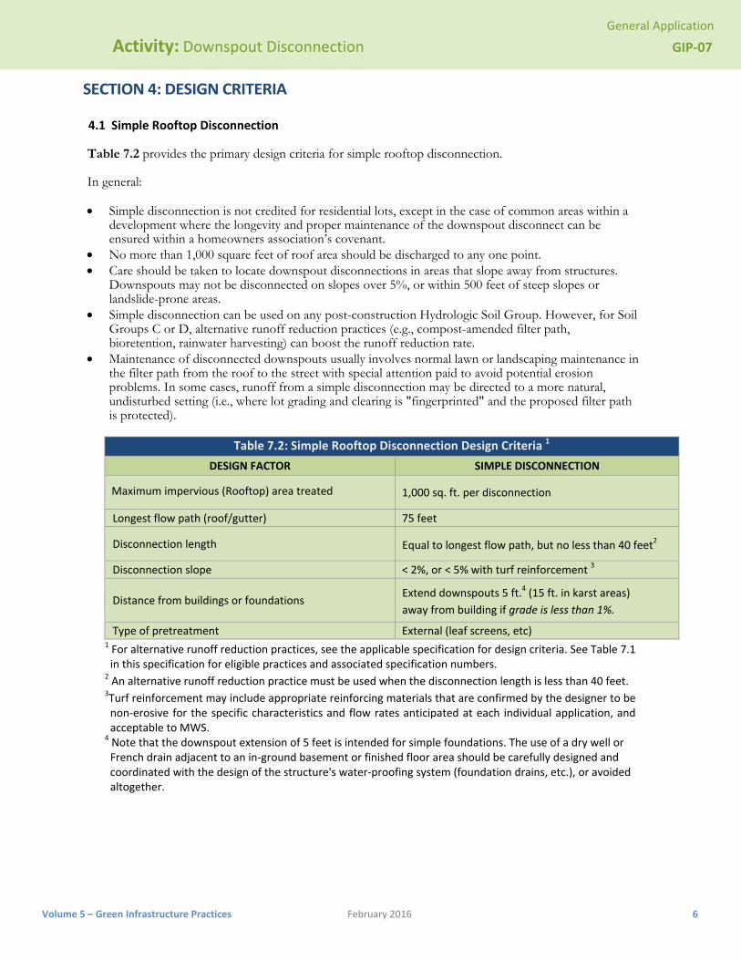
Table 7.2 provides the primary design criteria for simple rooftop disconnection.
In general:
Simple disconnection is not credited for residential lots, except in the case of common areas within a development where the longevity and proper maintenance of the downspout disconnect can be ensured within a homeowners association’s covenant.
No more than 1,000 square feet of roof area should be discharged to any one point. Care should be taken to locate downspout disconnections in areas that slope away from structures.
Downspouts may not be disconnected on slopes over 5%, or within 500 feet of steep slopes or landslide-prone areas.
Simple disconnection can be used on any post-construction Hydrologic Soil Group. However, for Soil Groups C or D, alternative runoff reduction practices (e.g., compost-amended filter path, bioretention, rainwater harvesting) can boost the runoff reduction rate.
Maintenance of disconnected downspouts usually involves normal lawn or landscaping maintenance in the filter path from the roof to the street with special attention paid to avoid potential erosion problems. In some cases, runoff from a simple disconnection may be directed to a more natural, undisturbed setting (i.e., where lot grading and clearing is "fingerprinted" and the proposed filter path is protected).
Table 7.2: Simple Rooftop Disconnection Design Criteria 1
DESIGN FACTOR SIMPLE DISCONNECTION
Maximum impervious (Rooftop) area treated 1,000 sq. ft. per disconnection
Longest flow path (roof/gutter) 75 feet
Disconnection length Equal to longest flow path, but no less than 40 feet2
Disconnection slope < 2%, or < 5% with turf reinforcement 3
Distance from buildings or foundations Extend downspouts 5 ft.4 (15 ft. in karst areas)
away from building if grade is less than 1%.
Type of pretreatment External (leaf screens, etc) 1 For alternative runoff reduction practices, see the applicable specification for design criteria. See Table 7.1 in this specification for eligible practices and associated specification numbers.
2 An alternative runoff reduction practice must be used when the disconnection length is less than 40 feet. 3Turf reinforcement may include appropriate reinforcing materials that are confirmed by the designer to be non‐erosive for the specific characteristics and flow rates anticipated at each individual application, and acceptable to MWS.
4 Note that the downspout extension of 5 feet is intended for simple foundations. The use of a dry well or French drain adjacent to an in‐ground basement or finished floor area should be carefully designed and coordinated with the design of the structure's water‐proofing system (foundation drains, etc.), or avoided altogether.
General Application
Activity: Downspout Disconnection GIP‐07
Volume 5 – Green Infrastructure Practices February 2016 7
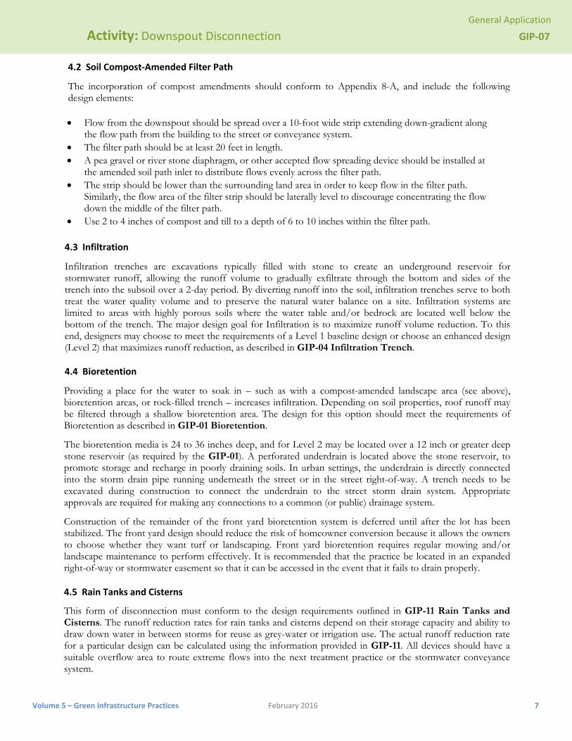
4.2 Soil Compost‐Amended Filter Path
The incorporation of compost amendments should conform to Appendix 8-A, and include the following design elements:
Flow from the downspout should be spread over a 10-foot wide strip extending down-gradient along the flow path from the building to the street or conveyance system.
The filter path should be at least 20 feet in length. A pea gravel or river stone diaphragm, or other accepted flow spreading device should be installed at
the amended soil path inlet to distribute flows evenly across the filter path. The strip should be lower than the surrounding land area in order to keep flow in the filter path.
Similarly, the flow area of the filter strip should be laterally level to discourage concentrating the flow down the middle of the filter path.
Use 2 to 4 inches of compost and till to a depth of 6 to 10 inches within the filter path.
4.3 Infiltration
Infiltration trenches are excavations typically filled with stone to create an underground reservoir for stormwater runoff, allowing the runoff volume to gradually exfiltrate through the bottom and sides of the trench into the subsoil over a 2-day period. By diverting runoff into the soil, infiltration trenches serve to both treat the water quality volume and to preserve the natural water balance on a site. Infiltration systems are limited to areas with highly porous soils where the water table and/or bedrock are located well below the bottom of the trench. The major design goal for Infiltration is to maximize runoff volume reduction. To this end, designers may choose to meet the requirements of a Level 1 baseline design or choose an enhanced design (Level 2) that maximizes runoff reduction, as described in GIP-04 Infiltration Trench.
4.4 Bioretention
Providing a place for the water to soak in – such as with a compost-amended landscape area (see above), bioretention areas, or rock-filled trench – increases infiltration. Depending on soil properties, roof runoff may be filtered through a shallow bioretention area. The design for this option should meet the requirements of Bioretention as described in GIP-01 Bioretention.
The bioretention media is 24 to 36 inches deep, and for Level 2 may be located over a 12 inch or greater deep stone reservoir (as required by the GIP-01). A perforated underdrain is located above the stone reservoir, to promote storage and recharge in poorly draining soils. In urban settings, the underdrain is directly connected into the storm drain pipe running underneath the street or in the street right-of-way. A trench needs to be excavated during construction to connect the underdrain to the street storm drain system. Appropriate approvals are required for making any connections to a common (or public) drainage system.
Construction of the remainder of the front yard bioretention system is deferred until after the lot has been stabilized. The front yard design should reduce the risk of homeowner conversion because it allows the owners to choose whether they want turf or landscaping. Front yard bioretention requires regular mowing and/or landscape maintenance to perform effectively. It is recommended that the practice be located in an expanded right-of-way or stormwater easement so that it can be accessed in the event that it fails to drain properly.
4.5 Rain Tanks and Cisterns
This form of disconnection must conform to the design requirements outlined in GIP-11 Rain Tanks and Cisterns. The runoff reduction rates for rain tanks and cisterns depend on their storage capacity and ability to draw down water in between storms for reuse as grey-water or irrigation use. The actual runoff reduction rate for a particular design can be calculated using the information provided in GIP-11. All devices should have a suitable overflow area to route extreme flows into the next treatment practice or the stormwater conveyance system.

General Application
Activity: Downspout Disconnection GIP‐07
Volume 5 – Green Infrastructure Practices February 2016 8
4.6 Stormwater Planter (Urban Bioretention)
This form of disconnection must conform to the design requirements for stormwater planters, as outlined in GIP-02 (Urban Bioretention). Foundation planters are a useful option to disconnect and treat rooftop runoff, particularly in ultra-urban areas. They consist of confined planters that store and/or infiltrate runoff in a soil bed to reduce runoff volumes and pollutant loads. Stormwater planters combine an aesthetic landscaping feature with a functional form of stormwater treatment. Stormwater planters generally receive runoff from adjacent rooftop downspouts and are landscaped with plants that are tolerant to periods of both drought and inundation. The two basic design variations for stormwater planters are the infiltration planter and the filter planter.
An infiltration planter filters rooftop runoff through soil in the planter followed by infiltration into soils below the planter. The recommended minimum depth is 30 inches, with the shape and length determined by architectural considerations. The planter should be sized to temporarily store at least 0.5 inch of runoff from the contributing rooftop area in a reservoir above the planter bed. Infiltration planters should be placed at least 10 feet away from a building to prevent possible flooding or basement seepage damage.
A filter planter has an impervious liner on the bottom. The minimum planter depth is 30 inches, with the shape and length determined by architectural considerations. Runoff is temporarily stored in a reservoir located above the planter bed. Overflow pipes are installed to discharge runoff when maximum ponding depths are exceeded, to avoid water spilling over the side of the planter. In addition, an underdrain is used to carry runoff to the storm sewer system. Since a filter planter is self-contained and does not infiltrate into the ground, it can be installed right next to a building.
All planters should be placed at grade level or above ground. They should be sized to allow captured runoff to drain out within four hours after a storm event. Plant materials should be capable of withstanding seasonally moist and dry conditions. Planting media should have an infiltration rate of at least 2 inches per hour. The sand and gravel on the bottom of the planter should have a minimum infiltration rate of 5 inches per hour. The planter can be constructed of stone, concrete, brick, wood or other durable material. If treated wood is used, care should be taken so that trace metals and creosote do not leach out of the planter.
SECTION 5: MAINTENANCE
The rooftop disconnection and supplementary treatment device must be covered by a drainage easement to allow inspection and maintenance and must also be included in the site’s Maintenance Document. Appendix C of Volume 1 of the SWMM contains more information about the Maintenance Document and includes an inspection checklist for Downspout Disconnection.
SECTION 6: AS‐BUILTS
After the downspout disconnection has been constructed, the developer must have an as-built certification conducted by a registered Professional Engineer. The as-built certification verifies that the SCM was installed as designed and approved. The following components must be addressed in the as-built certification: 1. Ensure disconnect is treating appropriate area size from either sheet flow or roof leader. 2. Ensure filter media depth is properly sized. 3. Ensure building setbacks are 5 ft down-gradient, 25 ft up-gradient. 4. Ensure underdrain and gravel layer (if required) have been properly installed. 5. If alternative practices have been utilized, insure that as-built requirements for those GIPs are also
certified using as-built section of the utilized GIP.
General Application
Activity: Downspout Disconnection GIP‐07
Volume 5 – Green Infrastructure Practices February 2016 9
SECTION 8: REFERENCES
Chesapeake Stormwater Network (CSN). 2008. Technical Bulletin 1: Stormwater Design Guidelines for Karst Terrain in the Chesapeake Bay Watershed. Version 1.0. Baltimore, MD. Available online at: http://www.chesapeakestormwater.net/all-things-stormwater/stormwater-guidance-for-karst-terrain-in-the-chesapeake-bay.html
City of Portland, Environmental Services. 2004. Portland Stormwater Management Manual. Portland, OR. http://www.portlandonline.com/bes/index.cfm?c=dfbbh
CWP. 2007. National Pollutant Removal Performance Database Version 3.0. Center for Watershed Protection, Ellicott City, MD.
Northern Virginia Regional Commission. 2007. Low Impact Development Supplement to the Northern Virginia BMP Handbook. Fairfax, Virginia.
Philadelphia Stormwater Management Guidance Manual. Available online at: http://www.phillyriverinfo.org/Programs/SubprogramMain.aspx?Id=StormwaterManual
Schueler, T., D. Hirschman, M. Novotney and J. Zielinski. 2007. Urban stormwater retrofit practices. Manual 3 in the Urban Subwatershed Restoration Manual Series. Center for Watershed Protection, Ellicott City, MD.
Schueler, T. 2008. Technical Support for the Baywide Runoff Reduction Method. Chesapeake Stormwater Network. Baltimore, MD. www.chesapeakestormwater.net
VADCR. 2011. Stormwater Design Specification No. 1: Rooftop (Impervious Surface) Disconnection, Version 1.9, March 1, 2011. Virginia Department of Conservation and Recreation. Available at: http://vwrrc.vt.edu/swc/NonProprietaryBMPs.html.
General Application
Activity: Downspout Disconnection GIP‐07
Volume 5 – Green Infrastructure Practices February 2016 10
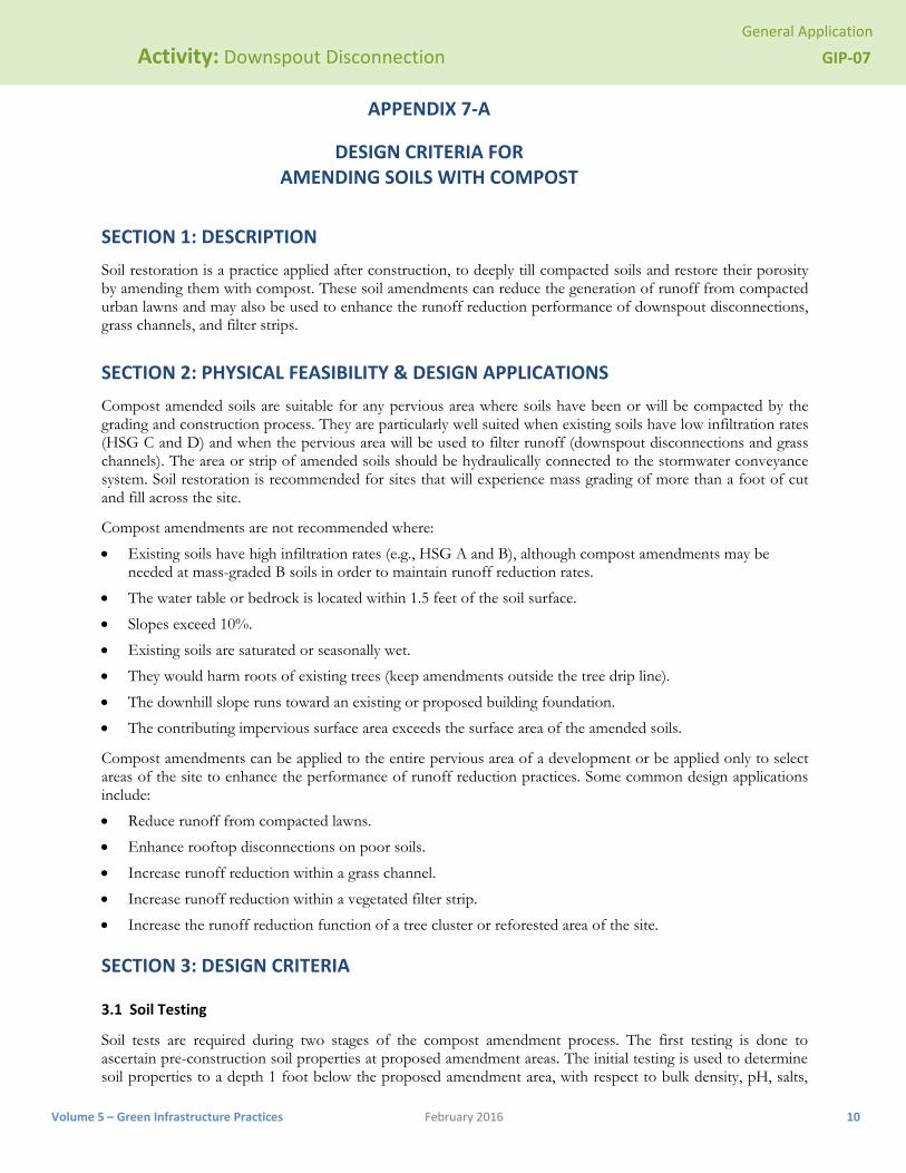
APPENDIX 7‐A
DESIGN CRITERIA FOR AMENDING SOILS WITH COMPOST
SECTION 1: DESCRIPTION
Soil restoration is a practice applied after construction, to deeply till compacted soils and restore their porosity by amending them with compost. These soil amendments can reduce the generation of runoff from compacted urban lawns and may also be used to enhance the runoff reduction performance of downspout disconnections, grass channels, and filter strips.
SECTION 2: PHYSICAL FEASIBILITY & DESIGN APPLICATIONS
Compost amended soils are suitable for any pervious area where soils have been or will be compacted by the grading and construction process. They are particularly well suited when existing soils have low infiltration rates (HSG C and D) and when the pervious area will be used to filter runoff (downspout disconnections and grass channels). The area or strip of amended soils should be hydraulically connected to the stormwater conveyance system. Soil restoration is recommended for sites that will experience mass grading of more than a foot of cut and fill across the site.
Compost amendments are not recommended where:
Existing soils have high infiltration rates (e.g., HSG A and B), although compost amendments may be needed at mass-graded B soils in order to maintain runoff reduction rates.
The water table or bedrock is located within 1.5 feet of the soil surface.
Slopes exceed 10%.
Existing soils are saturated or seasonally wet.
They would harm roots of existing trees (keep amendments outside the tree drip line).
The downhill slope runs toward an existing or proposed building foundation.
The contributing impervious surface area exceeds the surface area of the amended soils.
Compost amendments can be applied to the entire pervious area of a development or be applied only to select areas of the site to enhance the performance of runoff reduction practices. Some common design applications include:
Reduce runoff from compacted lawns.
Enhance rooftop disconnections on poor soils.
Increase runoff reduction within a grass channel.
Increase runoff reduction within a vegetated filter strip.
Increase the runoff reduction function of a tree cluster or reforested area of the site.
SECTION 3: DESIGN CRITERIA
3.1 Soil Testing
Soil tests are required during two stages of the compost amendment process. The first testing is done to ascertain pre-construction soil properties at proposed amendment areas. The initial testing is used to determine soil properties to a depth 1 foot below the proposed amendment area, with respect to bulk density, pH, salts,
General Application
Activity: Downspout Disconnection GIP‐07
Volume 5 – Green Infrastructure Practices February 2016 11
and soil nutrients. These tests should be conducted every 5000 square feet, and are used to characterize potential drainage problems and determine what, if any, further soil amendments are needed.
The second soil test is taken at least one week after the compost has been incorporated into the soils. This soil analysis should be conducted by a reputable laboratory to determine whether any further nutritional requirements, pH adjustment, and organic matter adjustments are necessary for plant growth. This soil analysis should be done in conjunction with the final construction inspection to ensure tilling or subsoiling has achieved design depths.
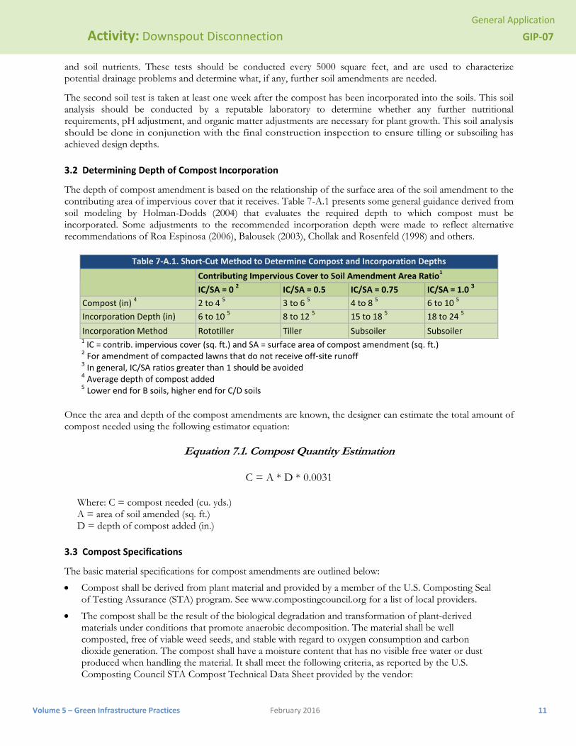
3.2 Determining Depth of Compost Incorporation
The depth of compost amendment is based on the relationship of the surface area of the soil amendment to the contributing area of impervious cover that it receives. Table 7-A.1 presents some general guidance derived from soil modeling by Holman-Dodds (2004) that evaluates the required depth to which compost must be incorporated. Some adjustments to the recommended incorporation depth were made to reflect alternative recommendations of Roa Espinosa (2006), Balousek (2003), Chollak and Rosenfeld (1998) and others.
Table 7‐A.1. Short‐Cut Method to Determine Compost and Incorporation Depths
Contributing Impervious Cover to Soil Amendment Area Ratio1
IC/SA = 0 2 IC/SA = 0.5 IC/SA = 0.75 IC/SA = 1.0 3
Compost (in) 4 2 to 4 5 3 to 6 5 4 to 8 5 6 to 10 5
Incorporation Depth (in) 6 to 10 5 8 to 12 5 15 to 18 5 18 to 24 5
Incorporation Method Rototiller Tiller Subsoiler Subsoiler 1 IC = contrib. impervious cover (sq. ft.) and SA = surface area of compost amendment (sq. ft.) 2 For amendment of compacted lawns that do not receive off‐site runoff 3 In general, IC/SA ratios greater than 1 should be avoided 4 Average depth of compost added 5 Lower end for B soils, higher end for C/D soils
Once the area and depth of the compost amendments are known, the designer can estimate the total amount of compost needed using the following estimator equation:
Equation 7.1. Compost Quantity Estimation
C = A * D * 0.0031
Where: C = compost needed (cu. yds.) A = area of soil amended (sq. ft.) D = depth of compost added (in.)
3.3 Compost Specifications
The basic material specifications for compost amendments are outlined below:
Compost shall be derived from plant material and provided by a member of the U.S. Composting Seal of Testing Assurance (STA) program. See www.compostingcouncil.org for a list of local providers.
The compost shall be the result of the biological degradation and transformation of plant-derived materials under conditions that promote anaerobic decomposition. The material shall be well composted, free of viable weed seeds, and stable with regard to oxygen consumption and carbon dioxide generation. The compost shall have a moisture content that has no visible free water or dust produced when handling the material. It shall meet the following criteria, as reported by the U.S. Composting Council STA Compost Technical Data Sheet provided by the vendor:
General Application
Activity: Downspout Disconnection GIP‐07
Volume 5 – Green Infrastructure Practices February 2016 12
a. 100% of the material must pass through a half inch screen b. The pH of the material shall be between 6 and 8
c. Manufactured inert material (plastic, concrete, ceramics, metal, etc.) shall be less than 1.0% by weight
d. The organic matter content shall be between 35% and 65% e. Soluble salt content shall be less than 6.0 mmhos/cm f. Maturity should be greater than 80% g. Stability shall be 7 or less
h. Carbon/nitrogen ratio shall be less than 25:1 i. Trace metal test result = “pass” j. The compost must have a dry bulk density ranging from 40 to 50 lbs./cu.ft.
SECTION 4: CONSTRUCTION
4.1 Construction Sequence
The construction sequence for compost amendments differs depending on whether the practice will be applied to a large area or a narrow filter strip, such as in a rooftop disconnection or grass channel. For larger areas, a typical construction sequence is as follows: Step 1. Prior to building, the proposed area should be deep tilled to a depth of 2 to 3 feet using a tractor and sub-soiler with two deep shanks (curved metal bars) to create rips perpendicular to the direction of flow. (This step is usually omitted when compost is used for narrower filter strips.) Step 2. A second deep tilling to a depth of 12 to 18 inches is needed after final building lots have been graded. Step 3. It is important to have dry conditions at the site prior to incorporating compost. Step 4. An acceptable compost mix is then incorporated into the soil using a roto-tiller or similar equipment at the volumetric rate of 1 part compost to 2 parts soil. Step 5. The site should be leveled and seeds or sod used to establish a vigorous grass cover. Lime or irrigation may initially be needed to help the grass grow quickly. Step 6. Areas of compost amendments exceeding 2,500 square feet should employ simple erosion control measures, such as silt fence, to reduce the potential for erosion and trap sediment.
4.2 Construction Inspection
Construction inspection involves digging a test pit to verify the depth of mulch, amended soil and scarification. A rod penetrometer should be used to establish the depth of uncompacted soil at one location per 10,000 square feet.

General Application
Activity: Downspout Disconnection GIP‐07
Volume 5 – Green Infrastructure Practices February 2016 13
SECTION 5: REFERENCES
Balousek. 2003. Quantifying decreases in stormwater runoff from deep-tilling, chisel-planting and compost amendments. Dane County Land Conservation Department. Madison, Wisconsin.
Chollak, T. and P. Rosenfeld. 1998. Guidelines for Landscaping with Compost-Amended Soils. City of Redmond Public Works. Redmond, WA. Available online at: http://www.ci.redmond.wa.us/insidecityhall/publicworks/environment/pdfs/compostamendedsoils.pdf
City of Portland. 2008. “Soil Specification for Vegetated Stormwater Facilities.” Portland Stormwater Management Manual. Portland, Oregon.
Composting Council (TCC). 1997. Development of a Landscape Architect Specification for Compost Utilization. Alexandria, VA. http://www.cwc.org/organics/org972rpt.pdf
Holman-Dodds, L. 2004. Chapter 6. Assessing Infiltration-Based Stormwater Practices. PhD Dissertation. Department of Hydroscience and Engineering. University of Iowa. Iowa City, IA.
Lenhart, J. 2007. “Compost as a Soil Amendment for Water Quality Treatment Facilities.” Proceedings: 2007 LID Conference. Wilmington, NC.
Low Impact Development Center. Guideline for Soil Amendments. Available online at: http://www.lowimpactdevelopment.org/epa03/soilamend.htm
Roa-Espinosa. 2006. An Introduction to Soil Compaction and the Subsoiling Practice. Technical Note. Dane County Land Conservation Department. Madison, Wisconsin.
Soils for Salmon. 2003. Soil Restoration and Compost Amendments. Available online at: http://www.soilsforsalmon.org/pdf/SoilsforSalmonLIDrev9-16-04.pdf

General Application
Activity: Downspout Disconnection GIP‐07
Volume 5 – Green Infrastructure Practices February 2016 14
This page intentionally left blank