7. integrate sustainable reintegrate with the community
TRANSCRIPT

SMALL AREA PLAN - DRAFT FOR PUBL IC COMMENT – JANUARY 28 , 2013
W A LT E R R E E D A R M Y M E D I C A L C E N T E R
PROGRESS INTERNAL DRAFT – FOR REVIEW PURPOSES ONLY
3 . REDEVELOPMENT FRAMEWORK RECOMMENDAT IONS70 3 .2 S I TE -W IDE URBAN DES IGN PR INC IPLES70
7. INTEGRATE SUSTAINABLE STRATEGIESThe redevelopment of the Walter Reed Site, fol-lowing its history of healing, presents an oppor-tunity to reimagine a large-scale campus-like development as an environmentally, economi-cally and socially sustainable new urban center. The District is committed to supporting the cre-ation of a highly sustainable new community. The SAP supports a regenerative project through a three-pronged strategy: 1) preservation and adaptive re-use; 2) community integration; and 3) environmental regeneration. Significant potential exists for: establishing a shared, bio-mass co- or tri-generation utility plant; generating stormwater management at a level that could generate reten-tion credits; exploring Photovoltaic (PV) farming; strategically targeting urban agriculture; and the re-exploring of the passive cooling systems origi-nally developed for the former WRAMC over 100 years ago.
Sustainability GoalsThe SAP incorporates the following specific goals included in the Reuse Plan:
• Net-zero energy by 2030; net-positive energy by 2040
• Existing buildings: ASHRAE 90.1+30%; New buildings ASHRAE 90.1+34%
• +100% renewable energy• 100% grey water reuse by 2020• 50% landfill waste reduction by 2020• 100% zero waste commitment by 2030• Food and yard waste composted on-site or
within approximately 30 miles• 100% recyclable material• +100% cool roof/green roof commitment
• Implement multi-modal modes of transportation
Sustainable Energy SystemsThe sustainable strategies for the development of the Walter Reed Site include a goal of net zero site energy by the year 2030 and carbon positive by the year 2050. As these terms are sometimes misunderstood, an explanation of all the terms and goals are included in the Reuse Plan.All of the energy systems will be connected to a central energy management system for monitor-ing and control. The energy management system will allow the performance of the various energy systems to be tracked to assure that energy goals are being achieved, to identify malfunctioning elements, to adjust system operation to optimize performance, and to bill the users appropriately.
Preserve and Adapt InnovativelyPreservation and reuse of the Site’s historically significant structures and landscapes provides a foundation for the sustainability vision. Reusing existing buildings is inherently more sustainable as it saves the waste and energy associated with demolition and new construction. Reuse will be coupled with innovative strategies for additions and renovations. The narrow floor plates of many of the historic buildings are well suited to natural ventilation and daylighting strategies. Mechani-cal and electrical systems and equipment can be upgraded to high efficiency systems. The cam-pus-like environment and large scale of the Plan allows centralized and shared utility systems not possible with smaller developments. The signifi-cant open space and natural topography of the Site can be utilized to manage stormwater runoff. This balanced approach honors the Site’s history while aspiring to the highest standards of a sus-tainable future.
Reintegrate with the CommunityFor the last hundred years the Walter Reed Site has been fenced off from the neighborhood. With its return to the District, an unparalleled opportu-nity exists to further high performance initiatives by integrating the Site with its surroundings in a way that promotes sustainability in the surround-ing neighborhood.The Walter Reed Site can serve as an example for the community and a way to educate a larger audience about sustainable practices.
Regenerate the EnvironmentJust as research at the Site once advanced the healing of the wounded, the Site itself can advance the capacity to heal the natural environ-ment by testing regenerative solutions. Regen-erative design represents the leading edge of sustainability and its highest aspirations – the creation of buildings and places that can have a net positive affect on the ecosystems of which they are a part. Whether the Walter Reed Site becomes regenerative in parts or as a whole, it is the standard to which this Site should aspire.The sustainability standards adopted in the development could include the best practices of today but also look forward to set the standards of tomorrow. As the rebirth of the Site unfolds over the next several decades, the opportunity exists to set a high standard of sustainability for the District of Columbia and a model for the rest of the country to follow.

SMALL AREA PLAN - DRAFT FOR PUBL IC COMMENT – JANUARY 28 , 2013
W A LT E R R E E D A R M Y M E D I C A L C E N T E R
PROGRESS INTERNAL DRAFT – FOR REVIEW PURPOSES ONLY
3 . REDEVELOPMENT FRAMEWORK RECOMMENDAT IONS713 .2 S I TE -W IDE URBAN DES IGN PR INC IPLES 71
PROJECT MISSION, GOALS AND OBJECTIVES
PW
Figure 4-88: Urban Agriculture (example). Common Good Farm, DC. Source: http://www.flickr.com/photos/christinboggs/sets/72157626780055856/detail/.
Figure 4-89: Rain Garden in Lansing, MI. Provided by Wiles Mensch Corporation - DC.
Figure 4-90: Potential Stormwater/Water Feature (example). Tanners Springs Park, Portland, OR. Source: http://fabulousportland.com/2010/02/19/sunshine-makes-me-happy/
Sustainable OpportunitiesFor the last hundred years, the Site was interna-tionally renowned as a center of innovation for medical research. There is an opportunity to build on this reputation and refocus the Site towards innovation in sustainable development. Further-more, the transformation into a sustainable site echoes the same changes happening in health-care from acute episodic care to chronic and long term care.
Existing Building Space The Walter Reed Site has 4.1 million square feet of existing building stock with a variety of uses, of which a third has some historic value and will require innovative adaptive reuse strategies. As for non-historic buildings at the end of their useful life, they present an opportunity for materials reuse and recycling through careful deconstruc-tion.
Open Space The Site has large expanses of open space and can provide a significant public amenity to the community. Native vegetation also provides opportunities for natural stormwater manage-ment without an increased irrigation burden.
TopographyThe Site topography is largely unchanged and approximately 50% pervious. Water naturally drains towards the southern portion of the Site where Cameron Creek was once above ground. The slopes and drainage patterns of the Site can be harnessed to filter stormwater.
TransportationThe Takoma Metrorail station is located near the Site. Numerous bus lines service the Site and a potential streetcar development may serve the Site in the future. Existing transportation sharing programs such as Zipcar and Capital Bikeshare
can be brought onto the Site to reduce occupants’ reliance on private vehicles and create a truly multi-modal community.
Separate Storm and Sewer SystemThe Site has separated sanitary and stormwa-ter systems which greatly facilitates progressive stormwater management practices. Although, the Site still feeds into the city’s combined sewer system, opportunities exist to exceed the Dis-trict’s requirements.
Power Generation The opportunity exists to leverage the existing campus power generation and distribution system to implement a central energy plant that could use a cogeneration or tri-generation system. Additional potential for on-site energy generation exists through the use of photovoltaics and solar hot water systems.
Cooling and HeatingThe cooling and heating requirements for the entire site are centrally provided from buildings in the north and south respectively. Systems are still in place to continue and perhaps to expand on this shared generation.
Teaching SustainabilityAs the current users leave and new uses arrive, a new audience will naturally come to appreciate the Site. This presents an opportunity to continu-ally educate users about sustainable practices within a living laboratory and at work within an everyday setting.

SMALL AREA PLAN - DRAFT FOR PUBL IC COMMENT – JANUARY 28 , 2013
W A LT E R R E E D A R M Y M E D I C A L C E N T E R
PROGRESS INTERNAL DRAFT – FOR REVIEW PURPOSES ONLY
3 . REDEVELOPMENT FRAMEWORK RECOMMENDAT IONS72 3 .2 S I TE -W IDE URBAN DES IGN PR INC IPLES72
PROJECT MISSION, GOALS AND OBJECTIVES
PW
RETAIL PARKING
EXISTING P1EXISTING P2
POWER & PARKING
OFFICE
RESIDENTIAL
DESTINATION RETAIL
COGENERATION PLANT
REUSE EXISTING PARKING GARAGEBelow Grade
GREEN ROOF + LID SWMAbove Power Plant(LID) Low Impact Development(SWM) Stormwater Management
SKYLIGHTSFor maximum daylighting
GREEN ROOFSOn all new buildings (where applicable)High Albedo Roofing (where green roof N/A)
PHOTOVOLTAICSOn all new buildings (where applicable)
WATER TREATMENT & STORAGECapture, treat and reuse greywater to reduce potable water demandBlackwater treatment by 2030
TODTransit-Oriented Development with Streetcar
WIDE ROW’SWide Rights of Way to allowsunlight into the buildings
REUSE FORMERHOSPITAL BASEMENT
RAIN GARDENSThroughout the siteCapture stormwater run-off
CISTERNSThroughout the siteWater collected at or below grade, typical to each building on site
DEDICATEDBICYCLE LANES
CAR SHARINGPROGRAMS
NATIVE PLANTSThroughout the site
Exhibit 4-91: Sustainable Framework. Source: Perkins+Will.
7. INTEGRATE SUSTAINABLE STRATEGIESThe exhibit below illustrates sustainability strate-gies—such as, rain gardens, photovoltaics, green roofs and skylights—that could be applied at the northern area of the Site as shown and through-out the rest of Site as well. This area of the Site has substantial space below grade available for reuse due to the projected demolition of hospi-tal Building 2. Central utilities could be located underground with open space amenities above.

SMALL AREA PLAN - DRAFT FOR PUBL IC COMMENT – JANUARY 28 , 2013
W A LT E R R E E D A R M Y M E D I C A L C E N T E R
PROGRESS INTERNAL DRAFT – FOR REVIEW PURPOSES ONLY
3 . REDEVELOPMENT FRAMEWORK RECOMMENDAT IONS733 .2 S I TE -W IDE URBAN DES IGN PR INC IPLES 73
THIS PAGE IS INTENTIONALLY LEFT BLANK
SMALL AREA PLAN - DRAFT FOR PUBL IC COMMENT – JANUARY 28 , 2013
W A LT E R R E E D A R M Y M E D I C A L C E N T E R
PROGRESS INTERNAL DRAFT – FOR REVIEW PURPOSES ONLY
3 . REDEVELOPMENT FRAMEWORK RECOMMENDAT IONS74 3 .3 SUB -AREA URBAN DES IGN PR INC IPLES74
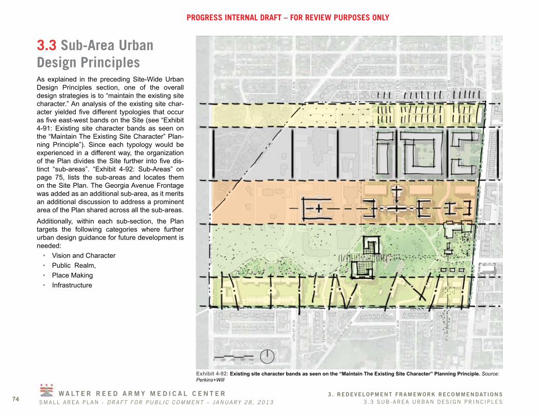
3.3 Sub-Area Urban Design PrinciplesAs explained in the preceding Site-Wide Urban Design Principles section, one of the overall design strategies is to “maintain the existing site character.” An analysis of the existing site char-acter yielded five different typologies that occur as five east-west bands on the Site (see “Exhibit 4-91: Existing site character bands as seen on the “Maintain The Existing Site Character” Plan-ning Principle”). Since each typology would be experienced in a different way, the organization of the Plan divides the Site further into five dis-tinct “sub-areas”. “Exhibit 4-92: Sub-Areas” on page 75, lists the sub-areas and locates them on the Site Plan. The Georgia Avenue Frontage was added as an additional sub-area, as it merits an additional discussion to address a prominent area of the Plan shared across all the sub-areas.Additionally, within each sub-section, the Plan targets the following categories where further urban design guidance for future development is needed:
• Vision and Character• Public Realm, • Place Making• Infrastructure
ALASKA A
VE N.W
.
16TH
ST.
N.W
.
14TH
ST.
N.W
.
14TH
PL.
N.W
.
ASPEN ST. N.W.ASPEN ST.
DAHLIA ST. N.W.
ELDER ST. N.W.
14TH
ST.
N.W
.
13TH
ST.
N.W
.
LUZO
N AVE.
N.W
.
13TH
PL.
N.W
.
13TH
ST.
N.W
.
12TH
ST.
N.W
.
GEO
RG
IA A
VE. N
.W.
FERN ST. N.W.
MAIN DR. N.W.
W. CAMERON DR. N
W
E. C
AMER
ON
DR. N
W
0’ 100’ 200’ 300’ 400’0’ 100’
SCALE: 1” = 100’
200’ 300’ 400’
Exhibit 4-92: Existing site character bands as seen on the “Maintain The Existing Site Character” Planning Principle. Source: Perkins+Will

SMALL AREA PLAN - DRAFT FOR PUBL IC COMMENT – JANUARY 28 , 2013
W A LT E R R E E D A R M Y M E D I C A L C E N T E R
PROGRESS INTERNAL DRAFT – FOR REVIEW PURPOSES ONLY
3 . REDEVELOPMENT FRAMEWORK RECOMMENDAT IONS753 .3 SUB -AREA URBAN DES IGN PR INC IPLES 75
SUB-AREA CATEGORIES
1
2
34
5
601
11
21
31
41
51
61
71
7
89
9
9
9
GEO
RG
IA A
VE. N
.W.
ALASKA A
VE N.W
.
16TH
ST.
N.W
.
14TH
ST.
N.W
.
14TH
PL.
N.W
.
ASPEN ST. N.W.ASPEN ST.
DAHLIA ST. N.W.
ELDER ST. N.W.14
TH S
T. N
.W.
13TH
ST.
N.W
.
LUZO
N AVE.
N.W
.
13TH
PL.
N.W
.
13TH
ST.
N.W
.
12TH
ST.
N.W
.
GEO
RG
IA A
VE. N
.W.
1
7
6
89
11
12
1814
15
1617
82
90
FERN ST. N.W.
MAIN DR. N.W.
W. CAMERON DR. NW
E. C
AMER
ON
DR.
NW
A BF
D E F
H
K
O
ILJ
P
Q
T
14 N
14 S
G
NM
R
S
V U
Y
WX
Z
B EC
1
2
4
3
5
Exhibit 4-93: Sub-Areas. Source: Perkins+Will.
ALASKA A
VE N.W
.
16TH
ST.
N.W
.
14TH
ST.
N.W
.
14TH
PL.
N.W
.
ASPEN ST. N.W.ASPEN ST.
DAHLIA ST. N.W.
ELDER ST. N.W.
14TH
ST.
N.W
.
13TH
ST.
N.W
.
LUZO
N AVE.
N.W
.
13TH
PL.
N.W
.
13TH
ST.
N.W
.
12TH
ST.
N.W
.
GEO
RG
IA A
VE. N
.W.
FERN ST. N.W.
MAIN DR. N.W.
W. CAMERON DR. N
W
E. C
AMER
ON
DR. N
W
0’ 100’ 200’ 300’ 400’
SUB-AREAS PLAN
FERN ST. N.W.
MAIN DR. N.W.
W. CAMERON DR. N
W
E. C
AMER
ON
DR. NW
A C
DE
F
H
K
O
ILJ
P
Q
T
14 N
14 S
G
NM
R
S
V U
Y
WX
Z
MAIN D
R. N.W
.
BB
E
F1.
12.
2 3.
3
4.
4
5.
5
Fern Street
Town Center
Institutional Core
Great Lawn ~ Cameron Glen
Aspen Street
Georgia Avenue Frontage

SMALL AREA PLAN - DRAFT FOR PUBL IC COMMENT – JANUARY 28 , 2013
W A LT E R R E E D A R M Y M E D I C A L C E N T E R
PROGRESS INTERNAL DRAFT – FOR REVIEW PURPOSES ONLY
3 . REDEVELOPMENT FRAMEWORK RECOMMENDAT IONS76 3 .3 SUB -AREA URBAN DES IGN PR INC IPLES76
1. FERN STREET
Vision and CharacterThe Fern Street sub-area is located in the north-ernmost portion of the Site, between Fern and Elder Streets. The WRAMC Reuse Plan recom-mends extending Elder Street west of Georgia Avenue, forming three small scale blocks, similar in size to the neighboring residential blocks to the north. A combination of existing single-family and duplex homes reflects the low-scale, residen-tial, character of the surrounding neighborhood. With new townhomes proposed along 12th, 13th, Elder and Fern Streets, the vision and character of this sub-area pays homage to the existing low-density residential uses fronting on Fern Street and provides a natural progression to higher-density uses proposed in the Town Center. A mixed-use building with ground floor retail at the intersection of Georgia Avenue and Fern Street reinforces commercial activity targeted along Georgia Avenue and may attract neighborhood-serving types of uses for residents.
1
2
34
5
601
11
21
31
41
51
61
71
7
89
9
9
9
GEO
RG
IA A
VE. N
.W.
ALASKA A
VE N.W
.
16TH
ST.
N.W
.
14TH
ST.
N.W
.
14TH
PL.
N.W
.
ASPEN ST. N.W.ASPEN ST.
DAHLIA ST. N.W.
ELDER ST. N.W.
14TH
ST.
N.W
.
13TH
ST.
N.W
.
LUZO
N AVE.
N.W
.
13TH
PL.
N.W
.
13TH
ST.
N.W
.
12TH
ST.
N.W
.
GEO
RG
IA A
VE. N
.W.
1
7
6
89
11
12
1814
15
1617
82
90
FERN ST. N.W.
MAIN DR. N.W.
W. CAMERON DR. NW
E. C
AMER
ON
DR.
NW
A BF
D E F
H
K
O
ILJ
P
Q
T
14 N
14 S
G
NM
R
S
V U
Y
WX
Z
B EC
0’ 100’ 200’ 300’
Exhibit 4-94: Sub-Area Key Plan - Fern Street. Source: Perkins+Will.

SMALL AREA PLAN - DRAFT FOR PUBL IC COMMENT – JANUARY 28 , 2013
W A LT E R R E E D A R M Y M E D I C A L C E N T E R
PROGRESS INTERNAL DRAFT – FOR REVIEW PURPOSES ONLY
3 . REDEVELOPMENT FRAMEWORK RECOMMENDAT IONS773 .3 SUB -AREA URBAN DES IGN PR INC IPLES 77
Figure 4-95: View looking north along Fern St. at a three-story residence just east of 13th St. Source: Perkins+Will.
Figure 4-96: View looking north along Fern St. at three-story residences in between 13th St. and 12th. St. Source: Perkins+Will.
Figure 4-97: View looking north along Fern St. at a two-story residence in between 13th St. and 12th. St. Source: Perkins+Will.
Figure 4-98: View looking north along Fern St. at duplex homes just west of Georgia Ave. Source: Perkins+Will.
Figure 4-99: View looking north along Fern St. at duplex homes just west of Georgia Ave. Source: Perkins+Will.
NEIGHBORHOOD CONTEXT

SMALL AREA PLAN - DRAFT FOR PUBL IC COMMENT – JANUARY 28 , 2013
W A LT E R R E E D A R M Y M E D I C A L C E N T E R
PROGRESS INTERNAL DRAFT – FOR REVIEW PURPOSES ONLY
3 . REDEVELOPMENT FRAMEWORK RECOMMENDAT IONS78 3 .3 SUB -AREA URBAN DES IGN PR INC IPLES78
1
2
34
5
601
11
21
31
41
51
61
71
7
89
9
9
9
GEO
RG
IA A
VE. N
.W.
ALASKA A
VE N.W
.
16TH
ST.
N.W
.
14TH
ST.
N.W
.
14TH
PL.
N.W
.
ASPEN ST. N.W.ASPEN ST.
DAHLIA ST. N.W.
ELDER ST. N.W.
14TH
ST.
N.W
.
13TH
ST.
N.W
.
LUZO
N AVE.
N.W
.
13TH
PL.
N.W
.
13TH
ST.
N.W
.
12TH
ST.
N.W
.
GEO
RG
IA A
VE. N
.W.
1
7
6
89
11
12
1814
15
1617
82
90
FERN ST. N.W.
MAIN DR. N.W.
W. CAMERON DR. NW
E. C
AMER
ON
DR.
NW
A BF
D E F
H
K
O
ILJ
P
Q
T
14 N
14 S
G
NM
R
S
V U
Y
WX
Z
B EC
0’ 100’ 200’ 300’
Exhibit 4-100: Sub-Area Key Plan 1. Source: Perkins+Will.
Place MakingAmenities Elder Street terminates at the boundary of the DOS Site to the west and creates a unique, yet intimate open space. The character of this area should mirror a quiet residential setting, making it an ideal location for a small scale community garden and a family recreation area.Building OrientationAll proposed new buildings and major entrances should be oriented towards the street or near corners wherever possible. Proposed townhomes in this sub-area should be designed to front along 12th, 13th, Fern and Elder Streets, thereby encouraging visual interest for pedestrians and further establishing the residential nature of the area. To help strengthen the Georgia Avenue and Fern Street intersection, the proposed mixed use building here would have access at grade and increase maximum allowable height at the corner. Alleyways proposed throughout the sub-area help further establish a “center of the block” feeling throughout rather than the having the backs of buildings facing sidewalks, and thus should be designed to provide a pleasant, safe environment for pedestrians to walk through and for residents to look at. The area between the extended 12th and 13th streets would have mostly residential frontages facing each other, possibly with neigh-borhood serving retail on occasion on the south side of Elder Street.Height and massingPursuant to the Reuse Plan, proposed building heights should range from 3 to 4-stories, with a Garage and Basement beneath. For example, the homes along Fern Street could be 3-stories reflecting similar heights of the existing homes across the street, while increasing the building height to 4-stories along Elder Street where the
grade is lower. The low-rise mixed-use build-ing facing Georgia Avenue in this area should fit within the varying building height context that currently prevails on Georgia Avenue. Building height and massing should be engaging to the pedestrian experience.
Public Realm The following are basic guidelines mainly for the public realm, defined as the area between the building facades — comprising the road, side-walk, site furnishings, trees and open spaces that combine to form the street’s character:
• Rights-of-Way: Provide minimum right-of-way (ROW) widths of 90 feet, compliant with DDOT’s standards and to enhance this sub-area’s opportunity for multi-modal con-nections. Other priorities should include sufficient room for front yard setbacks, curb-side stormwater management, on-street parking, and bike lanes as feasible.
• Pedestrian Zone: Explore minimum 20 feet pedestrian zones distance from building face to curb for landscaped front yards, pedes-trian circulation and curbside rain gardens and trees. Refer to DDOT’s standards for the planning and design of sidewalks and streets, such as tree planting guidelines and selection of site furnishings and materials.
• Green Elements: Integrate rain gardens in sidewalks for storm water management where feasible. Encourage the use of per-meable materials to manage stormwater runoff.
• Curb Cuts: Minimize curb cuts throughout the blocks.

SMALL AREA PLAN - DRAFT FOR PUBL IC COMMENT – JANUARY 28 , 2013
W A LT E R R E E D A R M Y M E D I C A L C E N T E R
PROGRESS INTERNAL DRAFT – FOR REVIEW PURPOSES ONLY
3 . REDEVELOPMENT FRAMEWORK RECOMMENDAT IONS793 .3 SUB -AREA URBAN DES IGN PR INC IPLES 79
2141
51
9
GEO
RG
IA A
VE. N
.W.
ELDER ST. N.W.
13TH
ST.
N.W
.
12TH
ST.
N.W
.
FERN ST. N.W.
A BF
D E F
H
K
O
ILJ
GB EC
2141
51
9
FERN ST. N.W.
A BF
D E F
H
K
O
ILJ
GB EC
EL.+292’EL.+310’
EL.+302’EL.+320’
“No Outlet” Street
Service Road
EL.+303’
Urban Agriculture/Community Garden
EL.+293’
EL.+299’
Mixed UseExisting
Single Family Homes
ExistingDuplex Homes
Townhomes
90’ ROW
95’ ROW
90’ ROW
90’ ROW
Exhibit 4-101: Sub-Area Plan - Fern Street. Source: Perkins+Will.
LRA Property Line
Garage & Basement
160’
50’ 20’ 20’ 20’ 50’
Building Yard Yard BuildingAlley
Residential Street Residential Street
Garage & Basement
Level 1
Level 2
Level 1
Level 2
EL.+320’
Existing
Retail Mezzanine Beyond EL.+292’
EL.+277’
EL.+267’
Existing P-1 & Retail
Existing P-2 Beyond
Central Utility Plant
4 Residential
3 Residential
2 Residential
1 Residential
5 Residential
SITE SECTION A
FERN ST.
10’
EL.+310’
ELDER ST.
Level 3Level 3
Level 4
0’ 20’ 40’ 60’
Exhibit 4-102: Fern Street Sub-Area Site Section. Source: Perkins+Will.
Exhibit 4-103: Site Section Key Plan - Fern Street. Source: Perkins+Will.
A

SMALL AREA PLAN - DRAFT FOR PUBL IC COMMENT – JANUARY 28 , 2013
W A LT E R R E E D A R M Y M E D I C A L C E N T E R
PROGRESS INTERNAL DRAFT – FOR REVIEW PURPOSES ONLY
3 . REDEVELOPMENT FRAMEWORK RECOMMENDAT IONS80 3 .3 SUB -AREA URBAN DES IGN PR INC IPLES80
Exhibit 4-104: Fern Street Site Section. Source: Perkins+Will.
~ 25’
SW
MP
lanter
6’
SW
MP
lanter
6’
Curb W
alk
18”
Curb W
alk
18”
Parallel
Parking
7’
Parallel
Parking
7’
Bike
Lane
5’
Bike
Lane
5’10’ 10’
Travel Lane
Travel Lane
44’Roadway
Building Face to Curb
Right-of-Way
1’ Gutter 1’ Gutter
90-100’
Sidew
alk
6-8’
~ 25’Building Face to Curb
Sidew
alk
6-8’
Planted
Area/
Front Yard
+/- 16.5”Pedestrian Zone
• Pedestrians Bikes: Pedestrians and bicy-clists are intended to move around primarily on the street grid. The streets in this sub-area should have designated bicycle lanes as well as sidewalks on both sides of the street.
• Loading and Service: Service alleyways through the center of each block with access from Elder Street will provide easy access to proposed uses and are located away from main entrances.
A. 12TH STREET, 13TH STREET AND ELDER STREET SECTION
2141
51
9
GEO
RG
IA A
VE. N
.W.
ELDER ST. N.W.
13TH
ST.
N.W
.
12TH
ST.
N.W
.
FERN ST. N.W.
A BF
D E F
H
K
O
ILJ
GB ECA A
A
Exhibit 4-105: Street Section Key Plan - Fern Street. Source: Perkins+Will.
• Parking: Pursuant to the Transportation Impact Study (TIS), one parking space per home is recommended for the townhomes. A dedicated, below grade parking garage, including an anticipated ratio of 0.5 spaces per unit should be included for the multi-family housing fronting Georgia Avenue. On-street parking would be permitted on all streets in this sub-area. See the Transporta-tion Impact Study for more information.

SMALL AREA PLAN - DRAFT FOR PUBL IC COMMENT – JANUARY 28 , 2013
W A LT E R R E E D A R M Y M E D I C A L C E N T E R
PROGRESS INTERNAL DRAFT – FOR REVIEW PURPOSES ONLY
3 . REDEVELOPMENT FRAMEWORK RECOMMENDAT IONS813 .3 SUB -AREA URBAN DES IGN PR INC IPLES 81
Exhibit 4-106: Pedestrian and Bicycle Mobility - Fern Street. Source: Perkins+Will. 21
41
51
9G
EOR
GIA
AVE
. N.W
.ELDER ST. N.W.
13TH
ST.
N.W
.
12TH
ST.
N.W
.
FERN ST. N.W.
Exhibit 4-107: Vehicular Mobility - Fern Street. Source: Perkins+Will.
PedestrianBicycle
PEDESTRIAN AND BICYCLE MOBILITY
2141
51
9
GEO
RG
IA A
VE. N
.W.
ELDER ST. N.W.
13TH
ST.
N.W
.
12TH
ST.
N.W
.
Service and/or ParkingPotential Streetcar
Street
VEHICULAR MOBILITY
Existing Signed Bicycle Route
Proposed On-Street Bicycle Lane
Proposed Shared Use Trail
Bicycle Legend
Proposed Shared Use Street
Existing On-Street Bicycle Lane

SMALL AREA PLAN - DRAFT FOR PUBL IC COMMENT – JANUARY 28 , 2013
W A LT E R R E E D A R M Y M E D I C A L C E N T E R
PROGRESS INTERNAL DRAFT – FOR REVIEW PURPOSES ONLY
3 . REDEVELOPMENT FRAMEWORK RECOMMENDAT IONS82 3 .3 SUB -AREA URBAN DES IGN PR INC IPLES82
2. TOWN CENTER
Vision & CharacterThe Town Center sub-area is located in the north-east portion of the Site and is bordered by Elder Street to the north and Dahlia Street to the south. The name of this sub-area is derived from the actual physical area that will serve as the Town Center, or “heart” of the new development being created here. The goal is for this Town Center to serve as a hub for the new development and the entire area. The actual Town Center is to be located between 12th Street and Georgia Avenue. It is the Georgia Avenue frontage that makes the success of this sub-area central to the new mix of commercial and residential uses that will be fully integrated into the existing commu-nity. The new Town Center would be the “pulse” of the entire development, where residential buildings with neighborhood serving retail uses at grade would frame a pedestrian plaza. Its location takes advantage of an existing pocket of healthy mature tree cover fronting Georgia Avenue. A potential streetcar loop around the Town Center would help enliven the space and reduce depen-dency on private vehicles, while attracting people to the area. The new central retail block, between 12th and 13th Streets, is the largest block on the Site and is ideal for a new large format destination retailer that will include a private rooftop courtyard and will be surrounded with residential uses. The pro-posed retail capacity is approximately 165,000 gross square feet. The ideal type of retail uses would draw customers from beyond a two-mile radius and could include department stores and/or wholesalers.
1
2
34
5
601
11
21
31
41
51
61
71
7
89
9
9
9
GEO
RG
IA A
VE. N
.W.
ALASKA A
VE N.W
.
16TH
ST.
N.W
.
14TH
ST.
N.W
.
14TH
PL.
N.W
.
ASPEN ST. N.W.ASPEN ST.
DAHLIA ST. N.W.
ELDER ST. N.W.
14TH
ST.
N.W
.
13TH
ST.
N.W
.
LUZO
N AVE.
N.W
.
13TH
PL.
N.W
.
13TH
ST.
N.W
.
12TH
ST.
N.W
.
GEO
RG
IA A
VE. N
.W.
1
7
6
89
11
12
1814
15
1617
82
90
FERN ST. N.W.
MAIN DR. N.W.
W. CAMERON DR. NW
E. C
AMER
ON
DR.
NW
A BF
D E F
H
K
O
ILJ
P
Q
T
14 N
14 S
G
NM
R
S
V U
Y
WX
Z
B EC
0’ 100’ 200’ 300’
Exhibit 4-108: Sub-Area Key Plan - Town Center. Source: Perkins+Will.

SMALL AREA PLAN - DRAFT FOR PUBL IC COMMENT – JANUARY 28 , 2013
W A LT E R R E E D A R M Y M E D I C A L C E N T E R
PROGRESS INTERNAL DRAFT – FOR REVIEW PURPOSES ONLY
3 . REDEVELOPMENT FRAMEWORK RECOMMENDAT IONS833 .3 SUB -AREA URBAN DES IGN PR INC IPLES 83
Figure 4-109: Town Center. Source: Perkins+Will and Lee & Associates, Inc.
Figure 4-110: View of the Town Center from across Georgia Avenue. Source: Perkins+Will and Lee & Associates, Inc.
1
2
34
5
601
11
21
31
41
51
61
71
7
89
9
9
9
GEO
RG
IA A
VE. N
.W.
ALASKA A
VE N.W
.
16TH
ST.
N.W
.
14TH
ST.
N.W
.
14TH
PL.
N.W
.
ASPEN ST. N.W.ASPEN ST.
DAHLIA ST. N.W.
ELDER ST. N.W.
14TH
ST.
N.W
.
13TH
ST.
N.W
.
LUZO
N AVE.
N.W
.
13TH
PL.
N.W
.
13TH
ST.
N.W
.
12TH
ST.
N.W
.
GEO
RG
IA A
VE. N
.W.
1
7
6
89
11
12
1814
15
1617
82
90
FERN ST. N.W.
MAIN DR. N.W.
W. CAMERON DR. NW
E. C
AMER
ON
DR.
NW
A BF
D E F
H
K
O
ILJ
P
Q
T
14 N
14 S
G
NM
R
S
V U
Y
WX
Z
B EC
0’ 100’ 200’ 300’
VIEW
Exhibit 4-111: Sub-Area Key Plan 2. Source: Perkins+Will.
1
2
34
5
601
11
21
31
41
51
61
71
7
89
9
9
9
GEO
RG
IA A
VE. N
.W.
ALASKA A
VE N.W
.
16TH
ST.
N.W
.
14TH
ST.
N.W
.
14TH
PL.
N.W
.
ASPEN ST. N.W.ASPEN ST.
DAHLIA ST. N.W.
ELDER ST. N.W.
14TH
ST.
N.W
.
13TH
ST.
N.W
.
LUZO
N AVE.
N.W
.
13TH
PL.
N.W
.
13TH
ST.
N.W
.
12TH
ST.
N.W
.
GEO
RG
IA A
VE. N
.W.
1
7
6
89
11
12
1814
15
1617
82
90
FERN ST. N.W.
MAIN DR. N.W.
W. CAMERON DR. NW
E. C
AMER
ON
DR.
NW
A BF
D E F
H
K
O
ILJ
P
Q
T
14 N
14 S
G
NM
R
S
V U
Y
WX
Z
B EC
0’ 100’ 200’ 300’
VIEW
Exhibit 4-112: Sub-Area Key Plan 2. Source: Perkins+Will.