7 miscdet-20
DESCRIPTION
misc detailsTRANSCRIPT

VOL. V - PART 2
PLAN
VIEW A-A
DATE: 11May2007 SHEET 1 of 12
INTEGRAL / JOINTLESS BRIDGES MISCELLANEOUS DETAILS
U-BACK WING DETAIL FILE NO. 20.06-1
VOL. V - PART 2
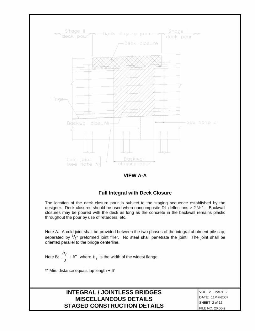
VIEW A-A
Full Integral with Deck Closure The location of the deck closure pour is subject to the staging sequence established by the designer. Deck closures should be used when noncomposite DL deflections > 2 ½ “. Backwall closures may be poured with the deck as long as the concrete in the backwall remains plastic throughout the pour by use of retarders, etc. Note A: A cold joint shall be provided between the two phases of the integral abutment pile cap, separated by 1/2” preformed joint filler. No steel shall penetrate the joint. The joint shall be oriented parallel to the bridge centerline.
"62+fb
where is the width of the widest flange. fbNote B:
** Min. distance equals lap length + 6”
DATE: 11May2007 SHEET 2 of 12
INTEGRAL / JOINTLESS BRIDGES MISCELLANEOUS DETAILS
STAGED CONSTRUCTION DETAILS FILE NO. 20.06-2

VOL. V - PART 2
VIEW A-A
Semi-Integral with Deck Closure The location of the deck closure pour is subject to the staging sequence established by the designer. Deck closures should be used when noncomposite DL deflections > 2 ½ “. Backwall closures may be poured with the deck as long as the concrete in the backwall remains plastic throughout the pour by use of retarders, etc.
"62+fb
where is the width of the widest flange. fbNote B:
** Min. distance equals lap length + 6”
DATE: 11May2007 SHEET 3 of 12
INTEGRAL / JOINTLESS BRIDGES MISCELLANEOUS DETAILS
STAGED CONSTRUCTION DETAILS FILE NO. 20.06-3

VOL. V - PART 2
VIEW A-A
Full Integral without Deck Closure Backwall closures may be poured with the deck as long as the concrete in the backwall remains plastic throughout the pour by use of retarders, etc. Note A: A cold joint shall be provided between the two phases of the integral abutment pile cap, separated by 1/2” preformed joint filler. No steel shall penetrate the joint. The joint shall be oriented parallel to the bridge centerline.
"62+fb
where is the width of the widest flange. fbNote B:
** Min. distance equals lap length + 6”
DATE: 11May2007 SHEET 4 of 12
INTEGRAL / JOINTLESS BRIDGES MISCELLANEOUS DETAILS
STAGED CONSTRUCTION DETAILS FILE NO. 20.06-4

VOL. V - PART 2
VIEW A-A
Semi-Integral without Deck Closure
Backwall closures may be poured with the deck as long as the concrete in the backwall remains plastic throughout the pour by use of retarders, etc.
"62+fb
where is the width of the widest flange. fbNote B:
** Min. distance equals lap length + 6”
DATE: 11May2007 SHEET 5 of 12
INTEGRAL / JOINTLESS BRIDGES MISCELLANEOUS DETAILS
STAGED CONSTRUCTION DETAILS FILE NO. 20.06-5

VOL. V - PART 2
The thickness of the Expanded Polystyrene (EPS) layer at the bottom of the integral backwall/abutment shall be determined using the following formula:
h height of integral backwall/abutment in inches
total thermal movement for entire temperature range in inches (total of expansion and contraction)
LΔ
EPS thickness in inches (shall not be < 10”) tEPS
( )[ ]L0.670.01h10EPSt Δ+= The designer shall ensure that the latest version of the “Special Provision for Elastic Inclusion” is placed in the contract. Elastic Inclusion is the combination of the elasticized EPS material and the geotextile separation membrane fabric.
SECTION SECTION Showing full integral with approach slab Showing full integral without approach slab
SECTION SECTION
Showing semi-integral with approach slab Showing semi-integral without approach slab
DATE: 11May2007 SHEET 6 of 12
INTEGRAL / JOINTLESS BRIDGES MISCELLANEOUS DETAILS
EXPANDED POLYSTYRENE (EPS) DETAILS FILE NO. 20.06-6

VOL. V - PART 2
WING REINFORCEMENT DETAIL Wings integral with footing
Wing shall be designed for moment and shear developed due to passive earth pressures. The designer shall ensure that the connection between the wing and the footing (including reinforcing steel embedment) is sufficient. Note to designer: Items in blocks are for designer's information only and are not to be placed on plans.
DATE: 11May2007 SHEET 7 of 12
INTEGRAL / JOINTLESS BRIDGES MISCELLANEOUS DETAILS ALTERNATE WING DETAILS FILE NO. 20.06-7
VOL. V - PART 2
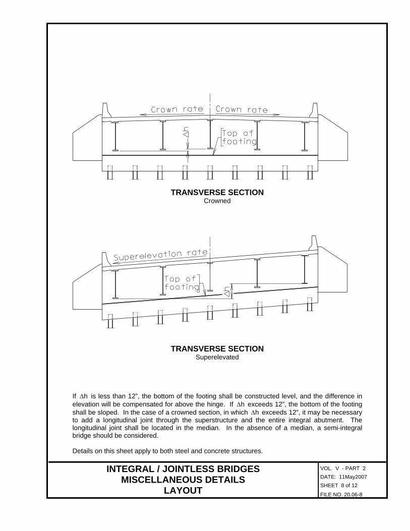
TRANSVERSE SECTION Crowned
TRANSVERSE SECTION Superelevated
If is less than 12”, the bottom of the footing shall be constructed level, and the difference in elevation will be compensated for above the hinge. If
hΔhΔ exceeds 12”, the bottom of the footing
shall be sloped. In the case of a crowned section, in which hΔ exceeds 12”, it may be necessary to add a longitudinal joint through the superstructure and the entire integral abutment. The longitudinal joint shall be located in the median. In the absence of a median, a semi-integral bridge should be considered. Details on this sheet apply to both steel and concrete structures.
DATE: 11May2007 SHEET 8 of 12
INTEGRAL / JOINTLESS BRIDGES MISCELLANEOUS DETAILS
LAYOUT FILE NO. 20.06-8

VOL. V - PART 2
SECTION A-A
This Alternate Backwall detail may be considered in situations where the length, skew, or geometry of the bridge precludes it from the integral bridge concept (See file no. 20.01-1 and 2). This detail combines the jointless concept with traditional concepts to provide a bridge that has a jointless superstructure and allows the use of uncoated weathering steel. Due to the increase in abutment quantities, the use of this detail should be based on initial cost and future maintenance cost analysis of the structure. For guidance on when to select this type of abutment detail, see the Selection Algorithm-20.01-5. Additional alternate backwall details are under development and will be revised at a later date. During the interim additional details and information of this detail are available upon request.
DATE: 11May2007 SHEET 9 of 12
INTEGRAL / JOINTLESS BRIDGES MISCELLANEOUS DETAILS
LAYOUT FILE NO. 20.06-9

VOL. V - PART 2
GIRDER END DETAIL
Integral bridge shall have a 3" diameter hole located as shown in detail. The location of the vent hole shall be on the high end of the bridge. If the bridge is level, then place hole on both ends. The hole is to allow water to vent trapped air during high water.
DATE: 11May2007 SHEET 10 of 12
INTEGRAL / JOINTLESS BRIDGES MISCELLANEOUS DETAILS
STEEL STRUCTURE VENT HOLE FILE NO. 20.06-10
VOL. V - PART 2
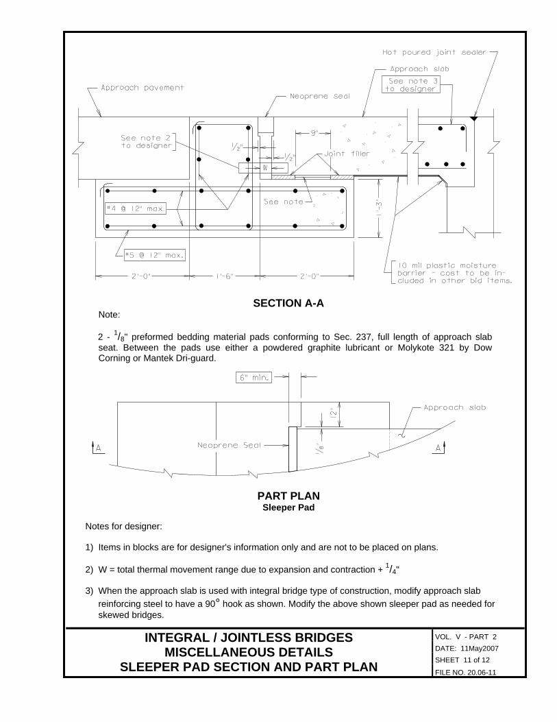
SECTION A-A Note:
1/ 2 - 8" preformed bedding material pads conforming to Sec. 237, full length of approach slab
seat. Between the pads use either a powdered graphite lubricant or Molykote 321 by Dow Corning or Mantek Dri-guard.
PART PLAN Sleeper Pad
Notes for designer: 1) Items in blocks are for designer's information only and are not to be placed on plans.
DATE: 11May2007 SHEET 11 of 12
INTEGRAL / JOINTLESS BRIDGES MISCELLANEOUS DETAILS
SLEEPER PAD SECTION AND PART PLAN FILE NO. 20.06-11
2) W = total thermal movement range due to expansion and contraction + 1/ " 4 3) When the approach slab is used with integral bridge type of construction, modify approach slab
reinforcing steel to have a 90° hook as shown. Modify the above shown sleeper pad as needed for skewed bridges.
VOL. V - PART 2
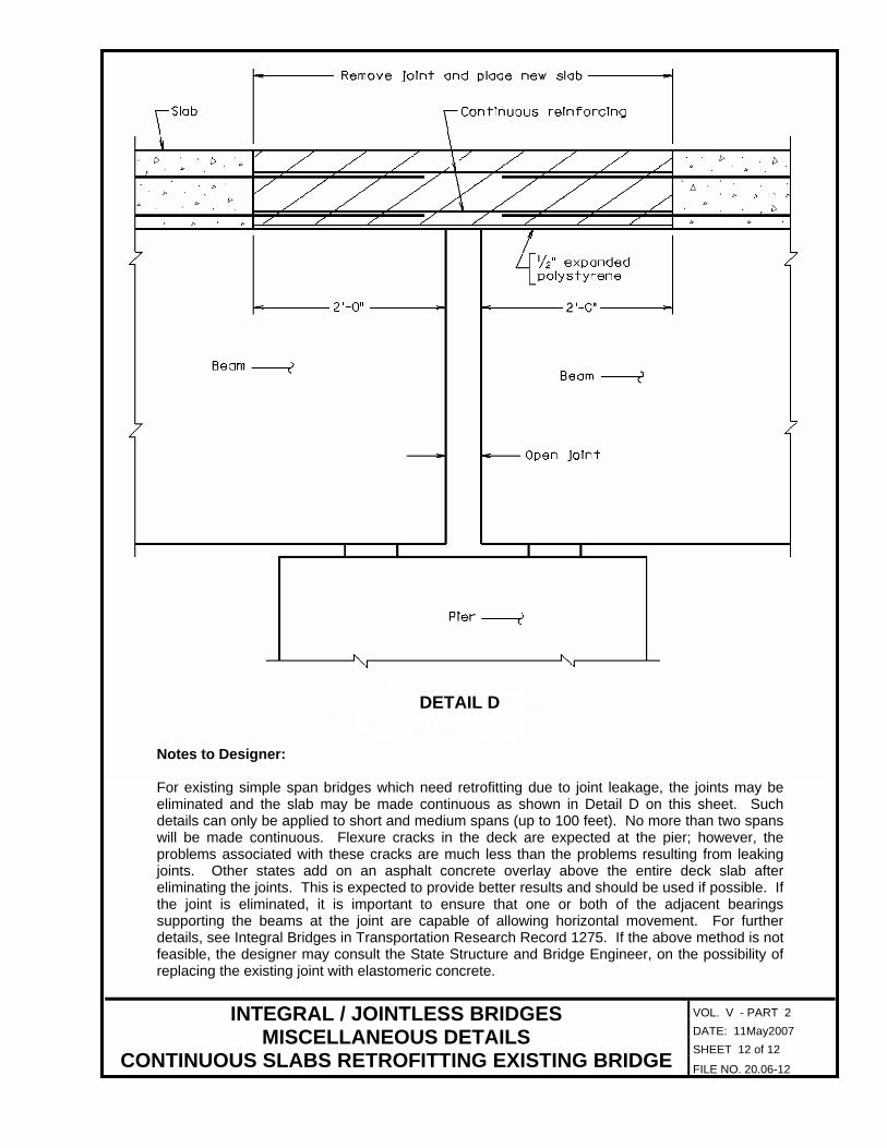
DETAIL D
Notes to Designer:
For existing simple span bridges which need retrofitting due to joint leakage, the joints may be eliminated and the slab may be made continuous as shown in Detail D on this sheet. Such details can only be applied to short and medium spans (up to 100 feet). No more than two spans will be made continuous. Flexure cracks in the deck are expected at the pier; however, the problems associated with these cracks are much less than the problems resulting from leaking joints. Other states add on an asphalt concrete overlay above the entire deck slab after eliminating the joints. This is expected to provide better results and should be used if possible. If the joint is eliminated, it is important to ensure that one or both of the adjacent bearings supporting the beams at the joint are capable of allowing horizontal movement. For further details, see Integral Bridges in Transportation Research Record 1275. If the above method is not feasible, the designer may consult the State Structure and Bridge Engineer, on the possibility of replacing the existing joint with elastomeric concrete.
DATE: 11May2007 SHEET 12 of 12
INTEGRAL / JOINTLESS BRIDGES MISCELLANEOUS DETAILS
CONTINUOUS SLABS RETROFITTING EXISTING BRIDGE FILE NO. 20.06-12