7 systems analysis and design in a changing world, fourth edition
TRANSCRIPT

7Systems Analysis and Design in a
Changing World, Fourth Edition

7
2
Learning Objectives
Develop use case diagrams
Write use case and scenario descriptions
Develop activity diagrams
Develop system sequence diagrams
Explain how UML diagrams work together to define functional requirements for the object-oriented approach

7
3
Object-Oriented Requirements
Object-oriented modeling notation is Unified Modeling Language (UML 2.0)
UML was accepted by Object Management Group (OMG) as standard modeling technique
Purpose of Object Management Group Promote theory and practice of object-oriented technology for
development of distributed systems Provide common architectural framework for OO
Object-oriented system requirements are specified and documented through process of building models
Modeling process starts with identification of use cases and problem domain classes (things in users’ work environment)
Business events trigger elementary business processes (EBP) that new system must address as use cases
Use cases define functional requirements

7
4
Object-Oriented Requirements Models Use case diagrams – identify actors and their use
cases (goals)
Use case descriptions – include details of a use case and how actors use the system
Systems sequence diagrams (SSDs) – define inputs and outputs and sequence of interactions between user and system for a use case
Activity diagrams – describe user and system activities for a use case
State machine diagrams – describe states of each object (we will not use these diagrams in MIS 160)

7
5
The System Activities—A Use Case/Scenario View
Use case analysis used to identify and define all business processes that system must support
Use case – an activity a system carried out, usually in response to a user request
Actor
Role played by user
Outside automation boundary

7
6
Techniques for Identifying Use Cases (Review from Chapter 5)
Identify user goals
Each goal at the elementary business process (EBP) level is a use case
EBP – task performed by one user in one place and in response to business event that adds measurable business value, and leaves system and data in consistent state
Event decomposition technique (event table)
CRUD analysis technique (create, read/report, update, delete) to ensure coverage

7
7
Use Case Diagram
Graphical UML diagram that summarizes information about actors and use cases
Simple diagram shows overview of functional requirements
Can have multiple use case diagrams
By subsystem
By actor

7
8
Simple Use Case with an Actor
7
9
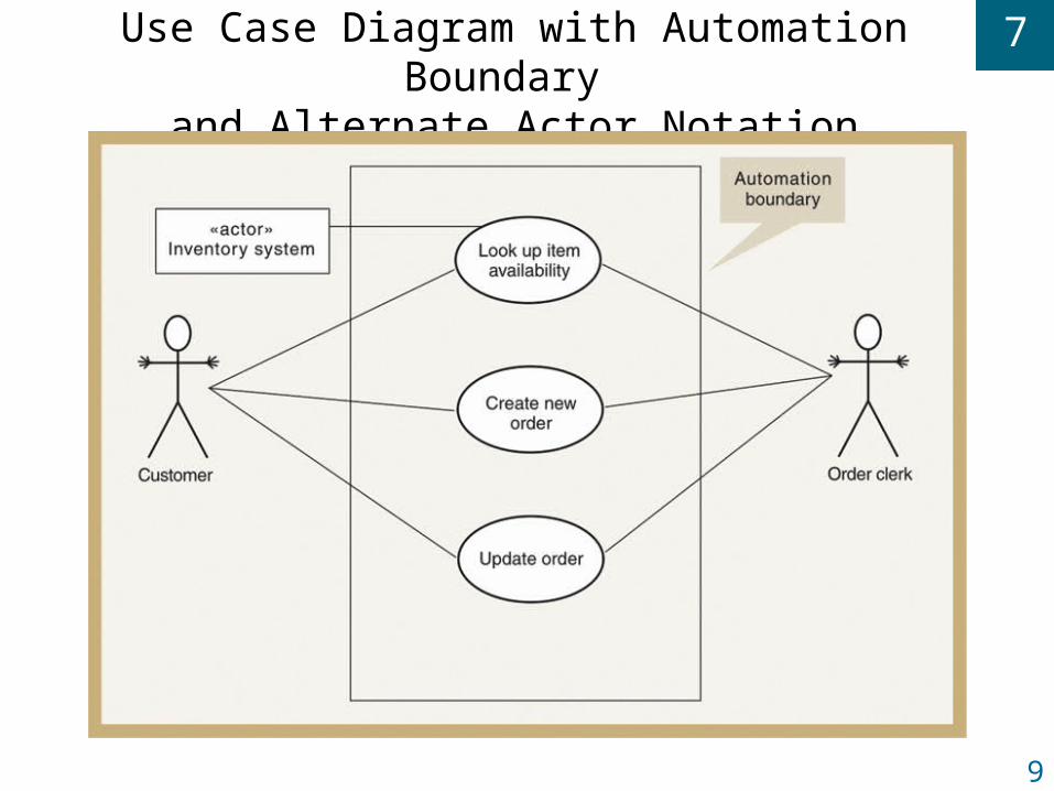
Use Case Diagram with Automation Boundary and Alternate Actor Notation

7
10
Use Cases of RMO Order Entry Subsystem (with package symbol)

7
11
<<Includes>> Relationship
Documents situation in which one use case requires the services of a common subroutine
Another use case is developed for this common subroutine
A common use case can be reused by multiple use cases

7
12
CRUD Analysis for Identifying/Confirming Use Cases
CRUD – create, read/report, update, delete
Information Engineering (IE) technique to identify event table or directly develop use case diagram
Compares identified use cases with domain model class diagram
Every class in class diagram must have use cases to support creating, reading, reporting, updating, and deleting object instances
Confirms system integration requirements

7
13
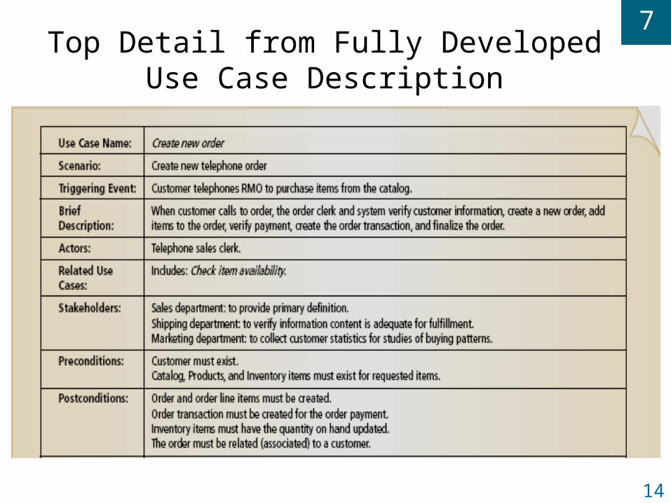
Use Case Description
Use case description provides details of preconditions, postconditions, sequence of activities, and exception conditions in use case
Describes actor interacting with computer system step-by-step to carry out business activity
May have several scenarios for a use case, each a specific use case instance
Three levels of detail: brief, intermediate, and fully developed description
Many analysts prefer to write narrative descriptions of use cases instead of drawing activity diagrams
7
14
Top Detail from Fully Developed Use Case Description

7
15
Middle Detail from Fully Developed Use Case Description

7
16
Bottom Detail from Fully Developed Use Case Description

7
17
Activity Diagrams
Used to document workflow of business process activities for each use case or scenario
Standard UML 2.0 diagram as seen in Chapter 4
Can support any level of use case description; a supplement to use case descriptions
Helpful in developing system sequence diagrams

7
18
Activity Diagram— Telephone
Order Scenario

7
19
Identifying Inputs and Outputs—The System Sequence Diagram
System sequence diagram (SSD) is type of UML 2.0 interaction diagram
Used to model input and output messaging requirements for a use case or scenario
Shows actor interacting with system
Shows sequence of interactions as messages during flow of activities
System is shown as one object: a “black box”

7
20
System Sequence Diagram (SSD) Notation

7
21
SSD Notation
Actor represented by a stick figure – a person (or role) that interacts with system by entering input data and receiving output data
Object is a rectangle with name of object underlined – shows individual object and not class of all similar objects ( :System for SSD )
Lifeline or object lifeline is a vertical line under object or actor to show passage of time for object
Message is labeled on arrows to show messages sent to or received by actor or system

7
22
SSD Lifelines
Vertical line under object or actor
Shows passage of time
If vertical line dashed
Creation and destruction of thing is not important for scenario
Long narrow rectangles
Activation lifelines emphasize that object is active only during part of scenario

7
23
SSD Messages
Internal events identified by the flow of objects in a scenario
Requests from one actor or object to another to do some action
Invoke a particular method

7
24
Repeating Message

7
25
Developing a System Sequence Diagram
Begin with detailed description of use case from fully developed form or activity diagram
Identify input messages
Describe message from external actor to system using message notation
Identify and add any special conditions on input message, including iteration and true/false conditions
Identify and add output return messages
7
26
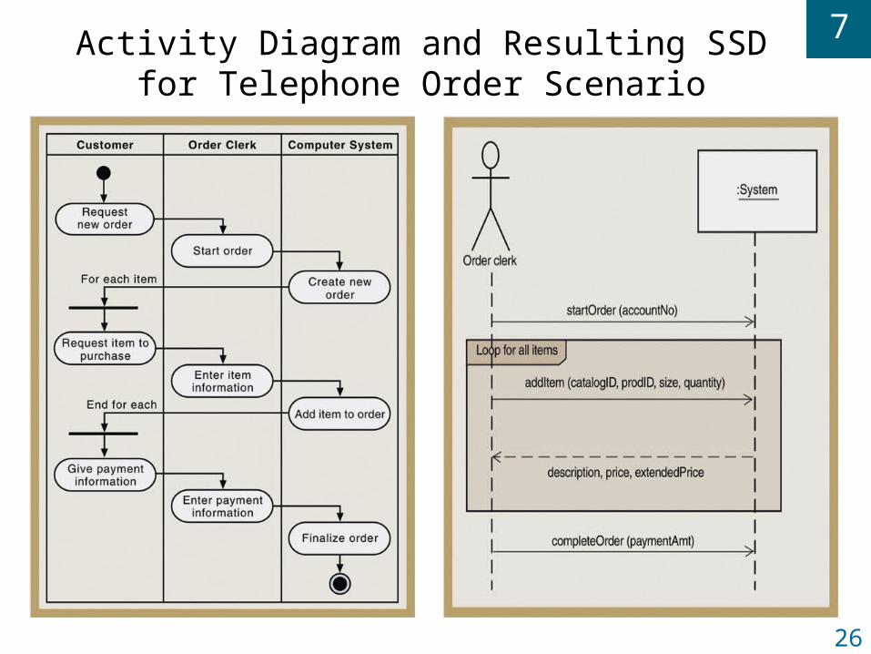
Activity Diagram and Resulting SSD for Telephone Order Scenario

7
27
Integrating Object-Oriented Models
Complete use case diagram is needed to understand total scope of new system
Domain model class diagrams should also be as complete as possible for entire system
With iterative approach, only construct use case descriptions, activity diagrams, and system sequence diagrams for use cases in iteration
Development of a new diagram often helps refine and correct previous diagrams

7
28
Relationships Between OO Requirements Models

7
29
Summary
Object-oriented approach has complete set of diagrams that define system requirements
Requirements specified using following models
Domain model class diagram (Chapter 5)
Use case diagrams (Chapter 7)
Use case detailed models, either descriptive formats or activity diagrams (Chapter 7)
System sequence diagrams (Chapter 7)