7.0 cistern design - n.c. department of agriculture and ... · 7.0 cistern design 7.1 overview of...
TRANSCRIPT
47
7.0 Cistern Design 7.1 Overview of Practice
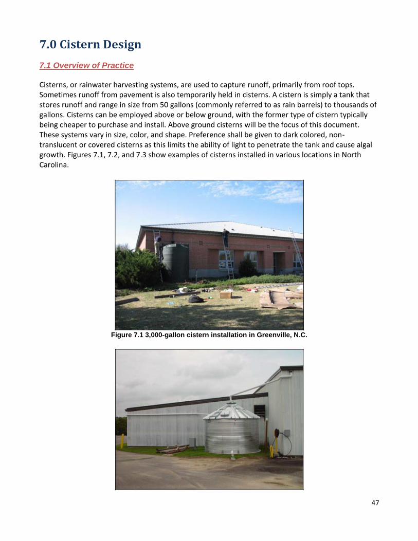
Cisterns, or rainwater harvesting systems, are used to capture runoff, primarily from roof tops. Sometimes runoff from pavement is also temporarily held in cisterns. A cistern is simply a tank that stores runoff and range in size from 50 gallons (commonly referred to as rain barrels) to thousands of gallons. Cisterns can be employed above or below ground, with the former type of cistern typically being cheaper to purchase and install. Above ground cisterns will be the focus of this document. These systems vary in size, color, and shape. Preference shall be given to dark colored, non-translucent or covered cisterns as this limits the ability of light to penetrate the tank and cause algal growth. Figures 7.1, 7.2, and 7.3 show examples of cisterns installed in various locations in North Carolina.
Figure 7.1 3,000-gallon cistern installation in Greenville, N.C.
48
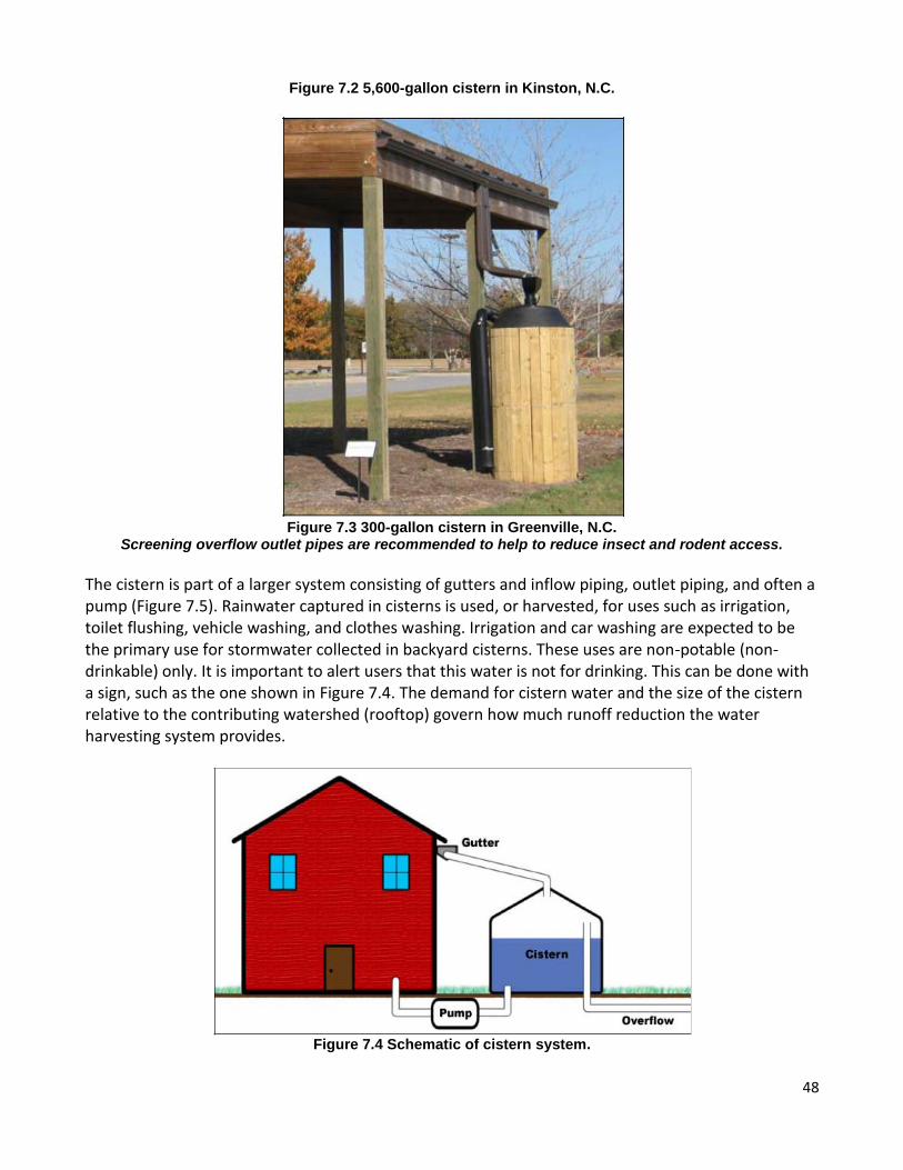
Figure 7.2 5,600-gallon cistern in Kinston, N.C.
Figure 7.3 300-gallon cistern in Greenville, N.C.
Screening overflow outlet pipes are recommended to help to reduce insect and rodent access.
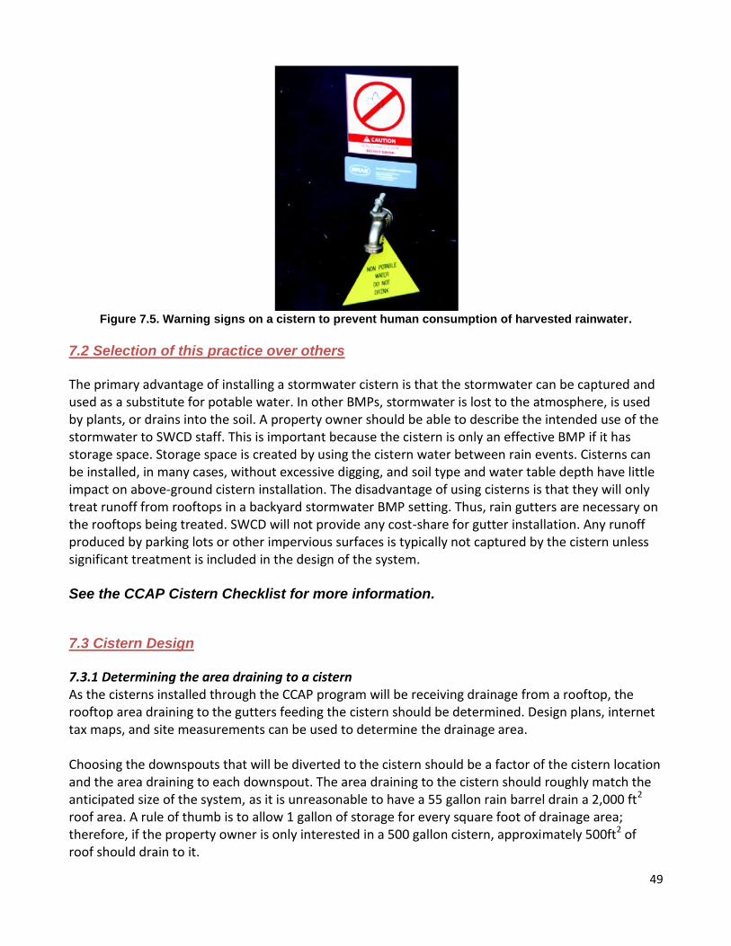
The cistern is part of a larger system consisting of gutters and inflow piping, outlet piping, and often a pump (Figure 7.5). Rainwater captured in cisterns is used, or harvested, for uses such as irrigation, toilet flushing, vehicle washing, and clothes washing. Irrigation and car washing are expected to be the primary use for stormwater collected in backyard cisterns. These uses are non-potable (non-drinkable) only. It is important to alert users that this water is not for drinking. This can be done with a sign, such as the one shown in Figure 7.4. The demand for cistern water and the size of the cistern relative to the contributing watershed (rooftop) govern how much runoff reduction the water harvesting system provides.
Figure 7.4 Schematic of cistern system.
49
Figure 7.5. Warning signs on a cistern to prevent human consumption of harvested rainwater.
7.2 Selection of this practice over others
The primary advantage of installing a stormwater cistern is that the stormwater can be captured and used as a substitute for potable water. In other BMPs, stormwater is lost to the atmosphere, is used by plants, or drains into the soil. A property owner should be able to describe the intended use of the stormwater to SWCD staff. This is important because the cistern is only an effective BMP if it has storage space. Storage space is created by using the cistern water between rain events. Cisterns can be installed, in many cases, without excessive digging, and soil type and water table depth have little impact on above-ground cistern installation. The disadvantage of using cisterns is that they will only treat runoff from rooftops in a backyard stormwater BMP setting. Thus, rain gutters are necessary on the rooftops being treated. SWCD will not provide any cost-share for gutter installation. Any runoff produced by parking lots or other impervious surfaces is typically not captured by the cistern unless significant treatment is included in the design of the system. See the CCAP Cistern Checklist for more information. 7.3 Cistern Design
7.3.1 Determining the area draining to a cistern As the cisterns installed through the CCAP program will be receiving drainage from a rooftop, the rooftop area draining to the gutters feeding the cistern should be determined. Design plans, internet tax maps, and site measurements can be used to determine the drainage area. Choosing the downspouts that will be diverted to the cistern should be a factor of the cistern location and the area draining to each downspout. The area draining to the cistern should roughly match the anticipated size of the system, as it is unreasonable to have a 55 gallon rain barrel drain a 2,000 ft2 roof area. A rule of thumb is to allow 1 gallon of storage for every square foot of drainage area; therefore, if the property owner is only interested in a 500 gallon cistern, approximately 500ft2 of roof should drain to it.

50
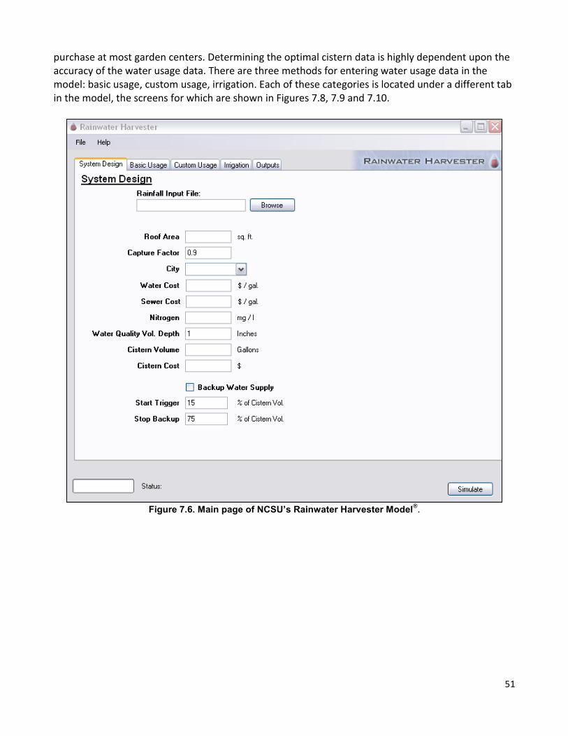
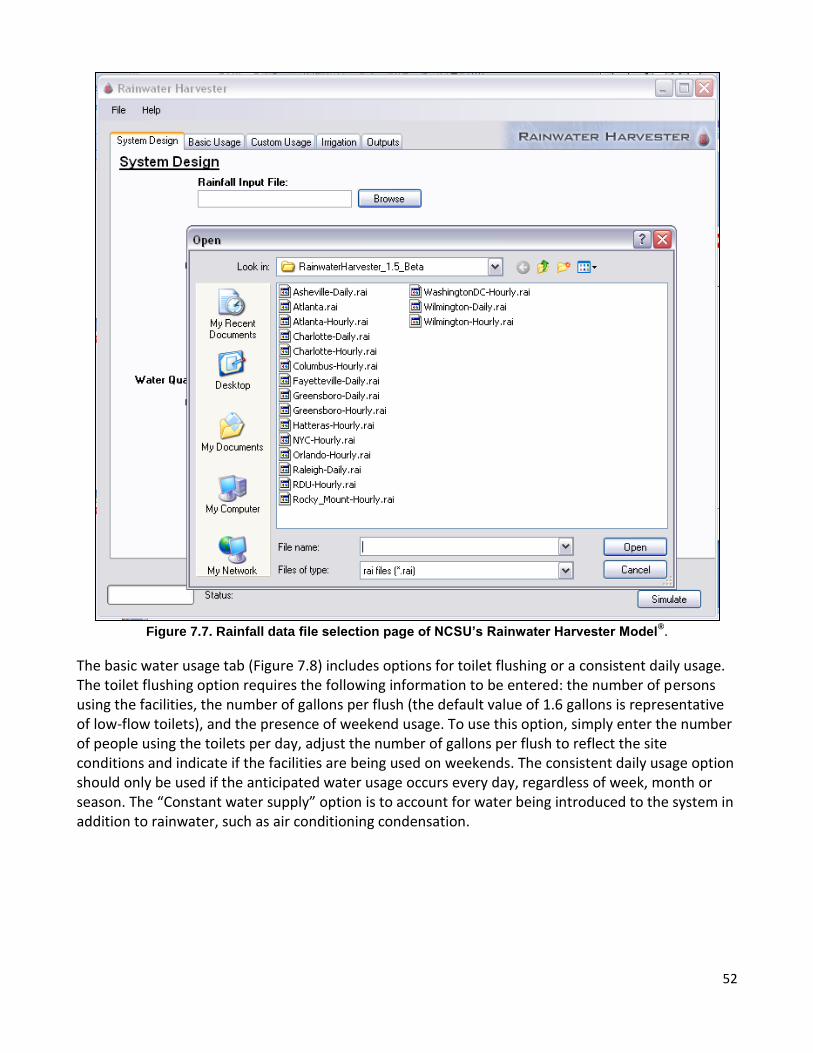
Extreme care should be taken when combining multiple downspouts into one pipe. Per North Carolina building code, gutters must be sized for a certain rainfall intensity to avoid water backing up into gutters and on the roof. When diverting downspouts to a cistern, the pipe draining a downspout should be at least the size of the cross-sectional area of the downspout. For example, if the existing downspout is 2”x3” (a cross-sectional area of 6in2), the pipe used to divert this downspout to the cistern should have an area of at least 6in2 (approximately that of a 3-inch diameter pipe). When combining downspouts, the resulting pipe should have a minimum cross-sectional area of the cumulative areas of the contributing pipe. For example, if two 2”x3” downspouts (or two 3”-diameter pipes) are combined, the resulting pipe should have a cross-sectional of at least 12in2 (approximately that of a 4-inch diameter pipe). Plugging downspout openings should be avoided, as the remaining openings in the gutters are not big enough to handle additional flow. An alternative to combining downspouts or plugging openings is to have multiples pipes entering the cistern (i.e. one pipe per downspout). 7.3.2 Cistern sizing The preferred way to determine the size of a cistern is to run the simple water budget model available on the following website: http://www.bae.ncsu.edu/topic/waterharvesting. This model simulates 30 years of actual rainfall data from several cities in North Carolina and couples this “supply” of water with user defined demands – such as the number of gallons of water used per week to irrigate and wash vehicles. Determining the optimal size of a cistern requires the user to conduct multiple iterations using varying cistern sizes and comparing the outputs from the model for different system sizes. The steps one should take to do this are outlined below. See the CCAP – Rainwater Harvest Guide for more information. The main page of the model is shown in Figure 7.6. Rainfall data are selected by clicking the “Browse” button under the “Rainfall Input File” heading. Clicking this button brings up the window shown in Figure 7.7. Users should select the file for the location closest to the site of interest. In most cases the daily data files are preferred for performing simulations. Hourly data files should only be used if hourly water usage information is available, as using hourly data requires longer run times and does not produce water quality results (water quality volume captured and annual nitrogen removed). After highlighting the appropriate data file, click “Open.” The user should then enter the area of roof draining to the cistern, the city closest to the site of interest, and the applicable water quality volume depth (1 inch for non-CAMA counties, 1.5 inches for CAMA counties). A cistern volume and cost must be entered for the initial simulation. Note that the model will not run if there is not a cost entered. A rule of thumb to use for this initial volume is 1 gallon of storage for every square foot of contributing roof area. The “Backup water supply” option is rarely used for some residential applications but can be utilized if a backup water source is included in the system design. To utilize this option, check the box beside “Backup water supply” and specify the start and stop trigger volume. This volume is expressed as a percent of the total storage volume of the cistern. The next step is entering water usage data into the model. Before a cistern is installed, it is highly recommended that the eventual operator of the cistern know how much water he/she is using on a daily basis. This information can be obtained using a simple hose-attached water meter, available for
51
purchase at most garden centers. Determining the optimal cistern data is highly dependent upon the accuracy of the water usage data. There are three methods for entering water usage data in the model: basic usage, custom usage, irrigation. Each of these categories is located under a different tab in the model, the screens for which are shown in Figures 7.8, 7.9 and 7.10.
Figure 7.6. Main page of NCSU’s Rainwater Harvester Model
®.
52
Figure 7.7. Rainfall data file selection page of NCSU’s Rainwater Harvester Model
®.
The basic water usage tab (Figure 7.8) includes options for toilet flushing or a consistent daily usage. The toilet flushing option requires the following information to be entered: the number of persons using the facilities, the number of gallons per flush (the default value of 1.6 gallons is representative of low-flow toilets), and the presence of weekend usage. To use this option, simply enter the number of people using the toilets per day, adjust the number of gallons per flush to reflect the site conditions and indicate if the facilities are being used on weekends. The consistent daily usage option should only be used if the anticipated water usage occurs every day, regardless of week, month or season. The “Constant water supply” option is to account for water being introduced to the system in addition to rainwater, such as air conditioning condensation.

53
Figure 7.8. Basic water usage page of NCSU’s Rainwater Harvester Model
®.
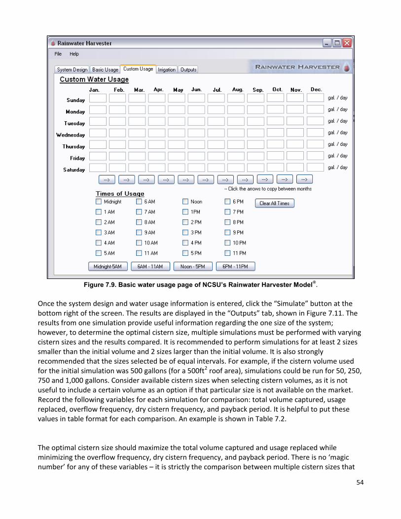
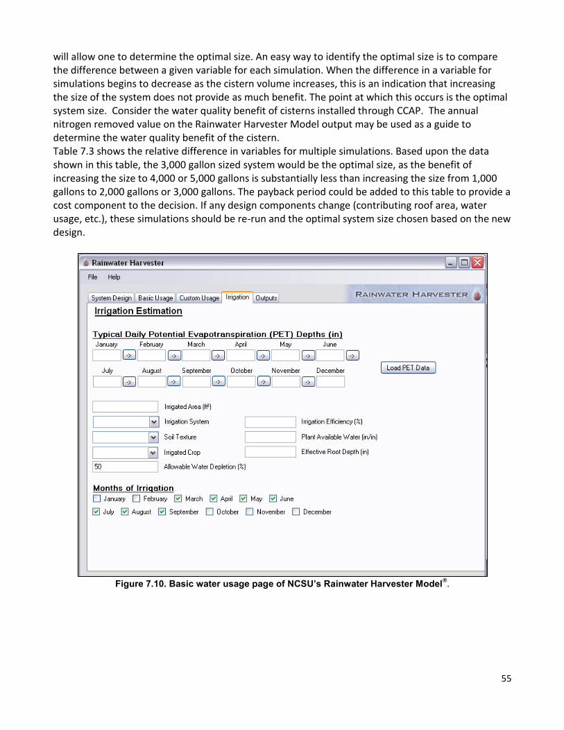
The “Custom water usage” option (Figure 7.9) offers more options in terms of water usage. Usage can be varied by month and day. The times of day that usage occurs may also be specified; however, this option should not be used unless hourly rainfall data is used for the simulation. If multiple time slots are checked in this option, the total usage entered is evenly distributed among the selected slots. The final option for entering water usage is the “Irrigation” tab (Figure 7.10). Note that this is only valid for irrigation systems that are controlled by soil water depletion (i.e. sensors measure soil moisture content and adjust irrigation frequency and amounts accordingly). To use this option, first load potential evapotranspiration (PET) data in the same manner rainfall data was selected. Next enter the amount of irrigated area, select the type of irrigation system, soil texture and irrigated crop. Entering these values will automatically fill in default values for irrigation efficiency, plant available water and effective root depth, although these values may be adjusted if the user thinks it necessary. The allowable water depletion is what dictates how dry the irrigated crop may get before the irrigation system is triggered. The default value for the model is 50%, but this can be adjusted by the user. Finally, the months that irrigation will occur should be specified at the bottom of the screen using the checkboxes.
54
Figure 7.9. Basic water usage page of NCSU’s Rainwater Harvester Model
®.
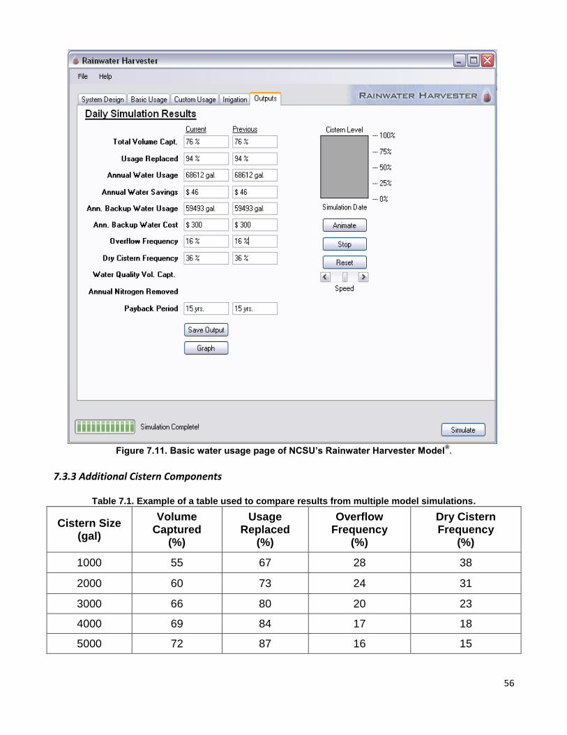
Once the system design and water usage information is entered, click the “Simulate” button at the bottom right of the screen. The results are displayed in the “Outputs” tab, shown in Figure 7.11. The results from one simulation provide useful information regarding the one size of the system; however, to determine the optimal cistern size, multiple simulations must be performed with varying cistern sizes and the results compared. It is recommended to perform simulations for at least 2 sizes smaller than the initial volume and 2 sizes larger than the initial volume. It is also strongly recommended that the sizes selected be of equal intervals. For example, if the cistern volume used for the initial simulation was 500 gallons (for a 500ft2 roof area), simulations could be run for 50, 250, 750 and 1,000 gallons. Consider available cistern sizes when selecting cistern volumes, as it is not useful to include a certain volume as an option if that particular size is not available on the market. Record the following variables for each simulation for comparison: total volume captured, usage replaced, overflow frequency, dry cistern frequency, and payback period. It is helpful to put these values in table format for each comparison. An example is shown in Table 7.2. The optimal cistern size should maximize the total volume captured and usage replaced while minimizing the overflow frequency, dry cistern frequency, and payback period. There is no ‘magic number’ for any of these variables – it is strictly the comparison between multiple cistern sizes that
55
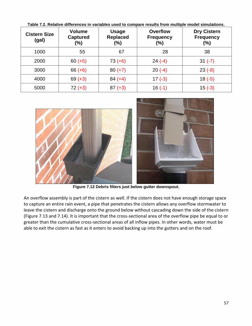
will allow one to determine the optimal size. An easy way to identify the optimal size is to compare the difference between a given variable for each simulation. When the difference in a variable for simulations begins to decrease as the cistern volume increases, this is an indication that increasing the size of the system does not provide as much benefit. The point at which this occurs is the optimal system size. Consider the water quality benefit of cisterns installed through CCAP. The annual nitrogen removed value on the Rainwater Harvester Model output may be used as a guide to determine the water quality benefit of the cistern. Table 7.3 shows the relative difference in variables for multiple simulations. Based upon the data shown in this table, the 3,000 gallon sized system would be the optimal size, as the benefit of increasing the size to 4,000 or 5,000 gallons is substantially less than increasing the size from 1,000 gallons to 2,000 gallons or 3,000 gallons. The payback period could be added to this table to provide a cost component to the decision. If any design components change (contributing roof area, water usage, etc.), these simulations should be re-run and the optimal system size chosen based on the new design.
Figure 7.10. Basic water usage page of NCSU’s Rainwater Harvester Model
®.
56
Figure 7.11. Basic water usage page of NCSU’s Rainwater Harvester Model
®.
7.3.3 Additional Cistern Components
Table 7.1. Example of a table used to compare results from multiple model simulations.
Cistern Size (gal)
Volume Captured
(%)
Usage Replaced
(%)
Overflow Frequency
(%)
Dry Cistern Frequency
(%)
1000 55 67 28 38
2000 60 73 24 31
3000 66 80 20 23
4000 69 84 17 18
5000 72 87 16 15
57
Table 7.2. Relative differences in variables used to compare results from multiple model simulations.
Cistern Size (gal)
Volume Captured
(%)
Usage Replaced
(%)
Overflow Frequency
(%)
Dry Cistern Frequency
(%)
1000 55 67 28 38
2000 60 (+5) 73 (+6) 24 (-4) 31 (-7)
3000 66 (+6) 80 (+7) 20 (-4) 23 (-8)
4000 69 (+3) 84 (+4) 17 (-3) 18 (-5)
5000 72 (+3) 87 (+3) 16 (-1) 15 (-3)
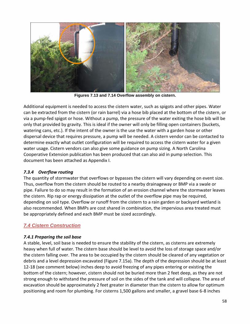
Figure 7.12 Debris filters just below gutter downspout.
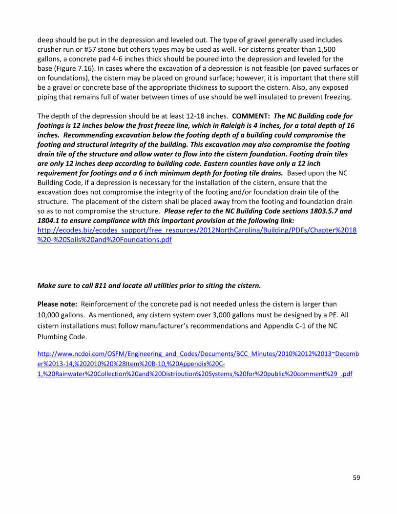
An overflow assembly is part of the cistern as well. If the cistern does not have enough storage space to capture an entire rain event, a pipe that penetrates the cistern allows any overflow stormwater to leave the cistern and discharge onto the ground below without cascading down the side of the cistern (Figure 7.13 and 7.14). It is important that the cross-sectional area of the overflow pipe be equal to or greater than the cumulative cross-sectional areas of all inflow pipes. In other words, water must be able to exit the cistern as fast as it enters to avoid backing up into the gutters and on the roof.
58
Figures 7.13 and 7.14 Overflow assembly on cistern.
Additional equipment is needed to access the cistern water, such as spigots and other pipes. Water can be extracted from the cistern (or rain barrel) via a hose bib placed at the bottom of the cistern, or via a pump-fed spigot or hose. Without a pump, the pressure of the water exiting the hose bib will be only that provided by gravity. This is ideal if the owner will only be filling open containers (buckets, watering cans, etc.). If the intent of the owner is the use the water with a garden hose or other dispersal device that requires pressure, a pump will be needed. A cistern vendor can be contacted to determine exactly what outlet configuration will be required to access the cistern water for a given water usage. Cistern vendors can also give some guidance on pump sizing. A North Carolina Cooperative Extension publication has been produced that can also aid in pump selection. This document has been attached as Appendix I.
7.3.4 Overflow routing The quantity of stormwater that overflows or bypasses the cistern will vary depending on event size. Thus, overflow from the cistern should be routed to a nearby drainageway or BMP via a swale or pipe. Failure to do so may result in the formation of an erosion channel where the stormwater leaves the cistern. Rip rap or energy dissipation at the outlet of the overflow pipe may be required, depending on soil type. Overflow or runoff from the cistern to a rain garden or backyard wetland is also recommended. When BMPs are cost shared in combination, the impervious area treated must be appropriately defined and each BMP must be sized accordingly. 7.4 Cistern Construction
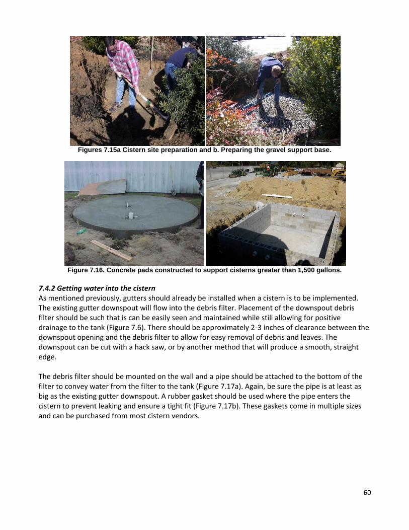
7.4.1 Preparing the soil base A stable, level, soil base is needed to ensure the stability of the cistern, as cisterns are extremely heavy when full of water. The cistern base should be level to avoid the loss of storage space and/or the cistern falling over. The area to be occupied by the cistern should be cleared of any vegetation or debris and a level depression excavated (Figure 7.15a). The depth of the depression should be at least 12-18 (see comment below) inches deep to avoid freezing of any pipes entering or existing the bottom of the cistern; however, cistern should not be buried more than 2 feet deep, as they are not strong enough to withstand the pressure of soil on the sides of the tank and will collapse. The area of excavation should be approximately 2 feet greater in diameter than the cistern to allow for optimum positioning and room for plumbing. For cisterns 1,500 gallons and smaller, a gravel base 6-8 inches
59
deep should be put in the depression and leveled out. The type of gravel generally used includes crusher run or #57 stone but others types may be used as well. For cisterns greater than 1,500 gallons, a concrete pad 4-6 inches thick should be poured into the depression and leveled for the base (Figure 7.16). In cases where the excavation of a depression is not feasible (on paved surfaces or on foundations), the cistern may be placed on ground surface; however, it is important that there still be a gravel or concrete base of the appropriate thickness to support the cistern. Also, any exposed piping that remains full of water between times of use should be well insulated to prevent freezing. The depth of the depression should be at least 12-18 inches. COMMENT: The NC Building code for footings is 12 inches below the frost freeze line, which in Raleigh is 4 inches, for a total depth of 16 inches. Recommending excavation below the footing depth of a building could compromise the footing and structural integrity of the building. This excavation may also compromise the footing drain tile of the structure and allow water to flow into the cistern foundation. Footing drain tiles are only 12 inches deep according to building code. Eastern counties have only a 12 inch requirement for footings and a 6 inch minimum depth for footing tile drains. Based upon the NC Building Code, if a depression is necessary for the installation of the cistern, ensure that the excavation does not compromise the integrity of the footing and/or foundation drain tile of the structure. The placement of the cistern shall be placed away from the footing and foundation drain so as to not compromise the structure. Please refer to the NC Building Code sections 1803.5.7 and 1804.1 to ensure compliance with this important provision at the following link: http://ecodes.biz/ecodes_support/free_resources/2012NorthCarolina/Building/PDFs/Chapter%2018%20-%20Soils%20and%20Foundations.pdf
Make sure to call 811 and locate all utilities prior to siting the cistern.
Please note: Reinforcement of the concrete pad is not needed unless the cistern is larger than
10,000 gallons. As mentioned, any cistern system over 3,000 gallons must be designed by a PE. All
cistern installations must follow manufacturer’s recommendations and Appendix C-1 of the NC
Plumbing Code.
http://www.ncdoi.com/OSFM/Engineering_and_Codes/Documents/BCC_Minutes/2010%2012%2013~Decemb
er%2013-14,%202010%20%28Item%20B-10,%20Appendix%20C-
1,%20Rainwater%20Collection%20and%20Distribution%20Systems,%20for%20public%20comment%29_.pdf
60
Figures 7.15a Cistern site preparation and b. Preparing the gravel support base.
Figure 7.16. Concrete pads constructed to support cisterns greater than 1,500 gallons.
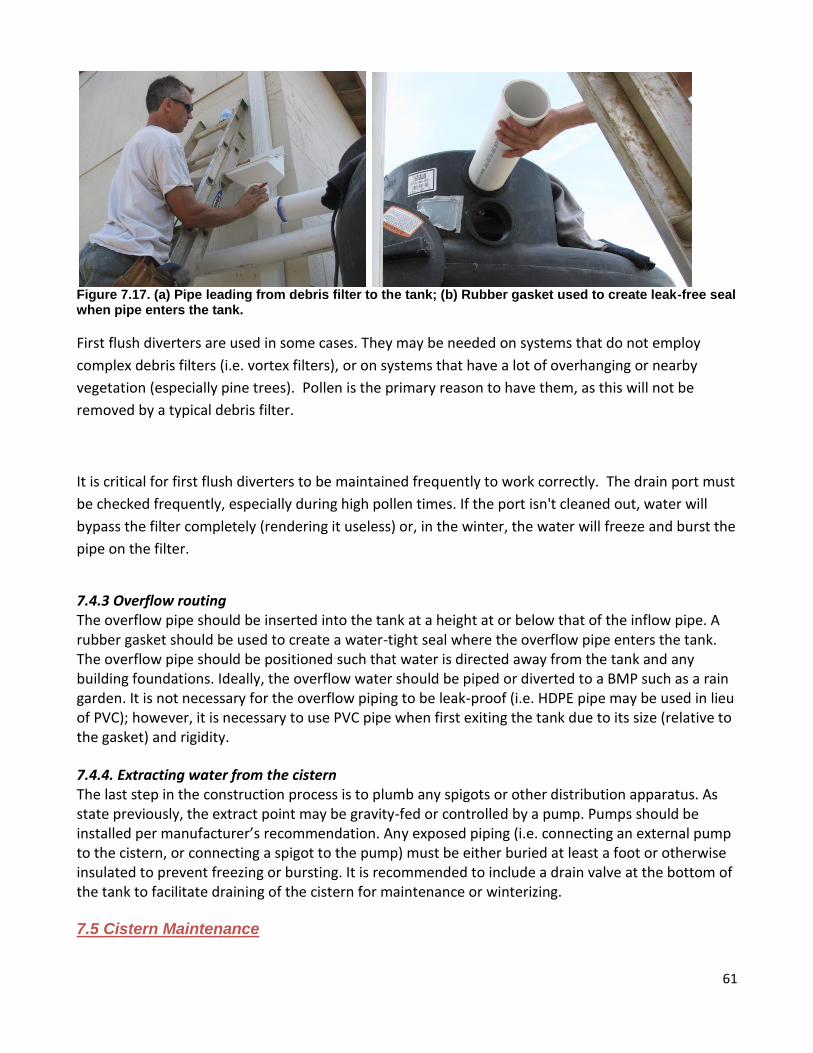
7.4.2 Getting water into the cistern As mentioned previously, gutters should already be installed when a cistern is to be implemented. The existing gutter downspout will flow into the debris filter. Placement of the downspout debris filter should be such that is can be easily seen and maintained while still allowing for positive drainage to the tank (Figure 7.6). There should be approximately 2-3 inches of clearance between the downspout opening and the debris filter to allow for easy removal of debris and leaves. The downspout can be cut with a hack saw, or by another method that will produce a smooth, straight edge. The debris filter should be mounted on the wall and a pipe should be attached to the bottom of the filter to convey water from the filter to the tank (Figure 7.17a). Again, be sure the pipe is at least as big as the existing gutter downspout. A rubber gasket should be used where the pipe enters the cistern to prevent leaking and ensure a tight fit (Figure 7.17b). These gaskets come in multiple sizes and can be purchased from most cistern vendors.
61
Figure 7.17. (a) Pipe leading from debris filter to the tank; (b) Rubber gasket used to create leak-free seal when pipe enters the tank.
First flush diverters are used in some cases. They may be needed on systems that do not employ
complex debris filters (i.e. vortex filters), or on systems that have a lot of overhanging or nearby
vegetation (especially pine trees). Pollen is the primary reason to have them, as this will not be
removed by a typical debris filter.
It is critical for first flush diverters to be maintained frequently to work correctly. The drain port must
be checked frequently, especially during high pollen times. If the port isn't cleaned out, water will
bypass the filter completely (rendering it useless) or, in the winter, the water will freeze and burst the
pipe on the filter.
7.4.3 Overflow routing The overflow pipe should be inserted into the tank at a height at or below that of the inflow pipe. A rubber gasket should be used to create a water-tight seal where the overflow pipe enters the tank. The overflow pipe should be positioned such that water is directed away from the tank and any building foundations. Ideally, the overflow water should be piped or diverted to a BMP such as a rain garden. It is not necessary for the overflow piping to be leak-proof (i.e. HDPE pipe may be used in lieu of PVC); however, it is necessary to use PVC pipe when first exiting the tank due to its size (relative to the gasket) and rigidity.
7.4.4. Extracting water from the cistern The last step in the construction process is to plumb any spigots or other distribution apparatus. As state previously, the extract point may be gravity-fed or controlled by a pump. Pumps should be installed per manufacturer’s recommendation. Any exposed piping (i.e. connecting an external pump to the cistern, or connecting a spigot to the pump) must be either buried at least a foot or otherwise insulated to prevent freezing or bursting. It is recommended to include a drain valve at the bottom of the tank to facilitate draining of the cistern for maintenance or winterizing. 7.5 Cistern Maintenance

62
Maintenance is crucial to cistern performance. Most notably, the gutters and the debris screen should be checked for leaves and other debris after every major storm event, particularly when a tree canopy is near a roof top. Failure to do so will result in water backing up into gutters and onto roofs due to clogging piping and filters. In-line pipe filters, pump intake filters, and spigot filters should be checked annually to ensure they don’t become clogged. Any hose or pipe connections associated with the cistern should be checked for leaks, especially after freezing temperatures. Some owners chose to decommission the system during winter months to prevent damage associated with freezing. To ‘winterize’ a system, drain all pipes, tanks and hoses associated with the cistern. Remove pumps and place them in a climate-controlled location protected from the weather. The drain valve at the bottom of the tank should be left open to allow any water entering the tank to drain out. This water may be diverted to a grassed area or a BMP as the overflow is. The cistern should be checked for stability prior to high-wind events (such as hurricanes or severe thunderstorms). If the cistern is consistently low on stormwater, it may become light and require some sort of anchoring system to keep it in pace. The owner of the cistern may want to fill it part way with potable water to prevent wind from tipping the cistern. A list of maintenance activities and their associated frequency is shown in Table 7.3. If water within the cistern is not used for an extended period of time, it may become stagnant and
develop a strong odor. To correct this problem, one should drain the stagnant water out of the
cistern and add 2 fluid ounces (1/4 cup) of bleach to the tank for every 1,000 gallons of storage. Be
sure to allow the tank to fill up prior to using water; otherwise the bleach will not be diluted enough
to safely use the water. Debris filters are often not fine enough to prevent pollen from entering the
tank. While this is generally not problematic, some people find pollen can also create an unpleasant
odor. To correct this, add bleach as described above.
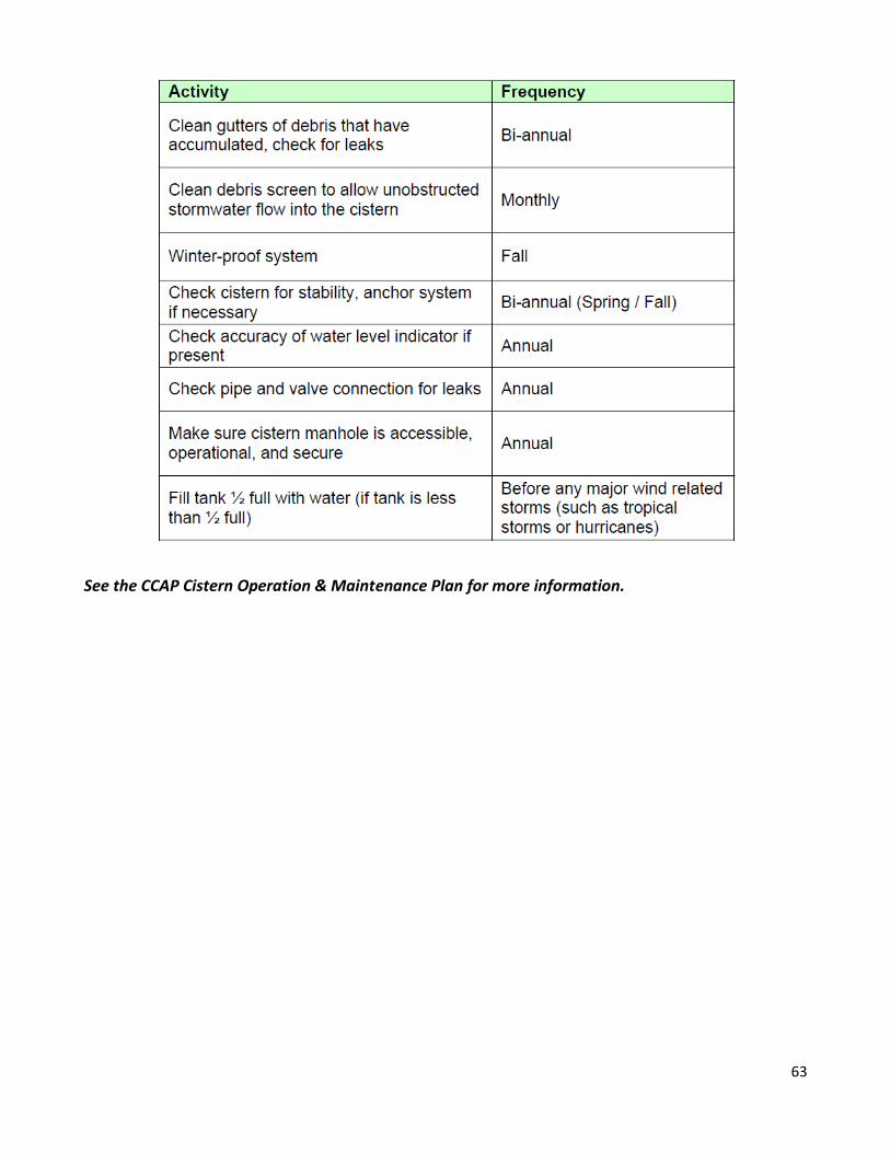
Table 7.3 Cistern Maintenance Activities
63
See the CCAP Cistern Operation & Maintenance Plan for more information.