700 va - 6000 va ups user's and installation...
TRANSCRIPT

700VA-6000VAUPS User’sandInstallationManual
EMCStatements
FCC Part 15
NOTE This equipment has been tested and found to comply with the limits for a Class B (700-2000VA) and Class A (3000VA-6000VA) digital device, pursuant to part 15 of the FCC rules. These limits are designed to provide reasonable protection against harmful interference in a residential installation. This equipment generates, uses and can radiate radio frequency energy and, if not installed and used in accordance with the instructions, may cause harmful interference to radio communications. However, there is no guarantee that interference will not occur in a particular installation. If this equipment does cause harmful interference to radio or television reception, which can be determined by turning the equipment off and on, the user is encouraged to try to correct the interference by one or more of the following measures:
• Reorient or relocate the receiving antenna.• Increase the separation between the equipment and the receiver.• Connect the equipment into an outlet on a circuit different from that to which the
receiver is connected.• Consult the dealer or an experienced radio/TV technician for help.
ICES-003
This Class B Interference Causing Equipment meets all requirements of the Canadian Interference Causing Equipment Regulations ICES–003.
Cet appareil numérique de la classe B respecte toutes les exigences du Reglement sur le matériel brouilleur du Canada.
Requesting a Declaration of Conformity
Units that are labeled with a CE mark comply with the following harmonic standards and EU directives:
• Harmonic Standards: EN 50091-1-1 and EN 50091-2• EU Directives:73/23/EEC, Council Directive on equipment designed for use within
certain voltage limits 93/68/EEC, Amending Directive 73/23/EEC 89/336/EEC, Council Directive relating to electromagnetic compatibility 92/31/EEC, Amending Directive 89/336/EEC relating to EMC
The EC Declaration of Conformity is available upon request for products with a CE mark. For copies of the EC Declaration of Conformity, contact:
Eaton Power Quality Oy Koskelontie 13, FIN-02920 Espoo Finland Phone: +358-9-452 661 Fax: +358-9-452 66 396 Copyright 2002 The contents of this manual are the copyright of the publisher and may not be reproduced (even extracts) unless permission granted. Every care has been taken to ensure the accuracy of the information contained in this manual, but no liability can be accepted for any errors or omission. The right to make design modifications is reserved.

700VA-6000VAUPSUser’sandInstallationManual
1017934 Revision D
CONTENTS
1. Introduction ...............................................................................................................5
2. System description .........................................................................................................5
2.1 General description ..................................................................................................5
2.2 System configuration ................................................................................................7
3. Safety information .....................................................................................................7
4. Storage and Unpacking ..............................................................................................8
4.1 Storage ......................................................................................................................8
4.2 Unpacking ................................................................................................................8
5. Installation .................................................................................................................9
5.1 Environment ............................................................................................................9
5.2 Rear panel views ......................................................................................................10
5.3 Connection to mains and loads 700 - 3000 VA .......................................................11
5.4 Connection to mains and load 5000 - 6000 VA ......................................................12
5.5 Default settings at factory ........................................................................................14
6. Computer and Alarm connections ............................................................................14
6.1 EPO port (emergency power off) ............................................................................15
6.2 Load segments .........................................................................................................15
7 Users guide to operations ..........................................................................................16
7.1 Starting and shutting down the UPS .......................................................................16
7.2 Control panel functions ..........................................................................................17
7.3 Interpreting UPS messages ......................................................................................20
7.4 Trouble shooting .....................................................................................................21
8. Maintenance .............................................................................................................22
8.1 Replacing batteries ..................................................................................................22
8.2 Service Bypass Option .............................................................................................23
9. Recycling the used UPS or batteries .........................................................................24
10. Warranty ...................................................................................................................24
11. Technical Specifications ............................................................................................25
11.1 Power Range 700-3000 VA ....................................................................................25
11.2 Power Range 5000-6000 VA ..................................................................................26
ImportantSafetyInstructionsSavetheseinstructions
This manual and safety manual contains important instructions that should be followed during installation and maintenance of the UPS and batteries.
CAUTION
Whenever the UPS is “On”, there may be dangerous voltage present at the unit’s outlets. This is true because the unit’s battery supplies power even if the unit is not plugged into the wall outlet. The unit contains dangerous voltages.
To reduce the risk of electric shock, install in a temperature-controlled and humidity- controlled indoor area free of conductive contaminants.
The power supply cord is intended to serve as the disconnect device. The socket-outlet shall be near the equipment and shall be easily accessible.
With the exception of the user-replaceable batteries, all servicing of this equipment must be performed by qualified service personnel.
Before maintenance or repair, all connections must be removed. Before maintenance, repair or shipment, the unit must be completely switched off and unplugged or disconnected.
Refer to your Safety Manual for additional safety instructions.
SpecialSymbols
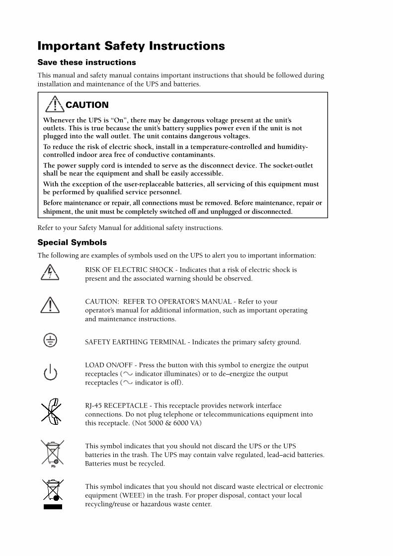
The following are examples of symbols used on the UPS to alert you to important information:
RISK OF ELECTRIC SHOCK - Indicates that a risk of electric shock is present and the associated warning should be observed.
CAUTION: REFER TO OPERATOR’S MANUAL - Refer to your operator’s manual for additional information, such as important operating and maintenance instructions.
SAFETY EARTHING TERMINAL - Indicates the primary safety ground.
LOAD ON/OFF - Press the button with this symbol to energize the output receptacles ( indicator illuminates) or to de–energize the output receptacles ( indicator is off).
RJ-45 RECEPTACLE - This receptacle provides network interface connections. Do not plug telephone or telecommunications equipment into this receptacle. (Not 5000 & 6000 VA)
This symbol indicates that you should not discard the UPS or the UPS batteries in the trash. The UPS may contain valve regulated, lead–acid batteries. Batteries must be recycled.
This symbol indicates that you should not discard waste electrical or electronic equipment (WEEE) in the trash. For proper disposal, contact your local recycling/reuse or hazardous waste center.
700 VA - 6000 VA UPS User’s and Installation Manual
1017934 Revision D
�
1. IntroductionThis user’s manual gives basic information about your single phase 700 – 6000 VA, uninterrupt-ible power systems, their basic function, how to use them and what to do in case of trouble. Instructions for shipping, storing, handling and installing the equipment are also given.
The planning guidelines of this manual describe only the specific demands of UPS units. Local legislation and regulations for electrical installations must be followed in the UPS installation.
The UPS system must be installed according to the instructions in this manual. Fixed installa-tions may be performed by qualified personnel only. Failure to recognize the electrical hazards could prove fatal.
2. SystemdescriptionAn UPS (Uninterruptible Power System) protects different types of sensitive electrical equip-ment: computers, workstations, sales terminals, critical instrumentation, telecommunications systems, process control systems etc. The UPS protects them from problems associated with utility power or poor quality, or a complete loss of power.
Sensitive electrical equipment needs protection from electrical interference. Interference from outside the facility (such as lightning, power company accidents and radio transmissions) and interference from inside facility (e.g. from motors, air conditioners, vending machines and arc welders) can create problems in the AC power. The problems can be: power outage, low or high voltage, slow voltage fluctuations, frequency variations, differential and common-mode noise, transients etc.
The UPS cleans the utility AC power, maintains a constant voltage and if needed isolates the output to the critical load. These actions help to keep power line problems from reaching the critical systems, where they can damage software and hardware and cause the equipment to operate erratically.
2.1 GeneraldescriptionThis UPS is a double conversion on-line UPS that conditions the raw mains and supplies con-tinuous, clean single-phase power to the critical systems. While feeding the load the UPS also keeps the battery constantly charged. If utility power fails, the UPS will continue to supply clean power to the load without any interruption.
If the power failure outlasts the backup time the UPS will shut down in order to prevent a total discharge of the battery. When the line voltage is restored the UPS will start up again automati-cally providing power to the critical load and recharge the batteries.
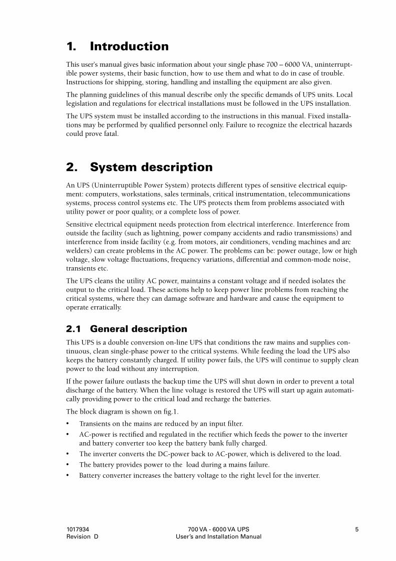
The block diagram is shown on fig.1.
• Transients on the mains are reduced by an input filter.
• AC-power is rectified and regulated in the rectifier which feeds the power to the inverter and battery converter too keep the battery bank fully charged.
• The inverter converts the DC-power back to AC-power, which is delivered to the load.
• The battery provides power to the load during a mains failure.
• Battery converter increases the battery voltage to the right level for the inverter.
700 VA - 6000 VA UPS User’s and Installation Manual
1017934 Revision D
6
Fig.1.Block diagram
EfficiencyOptimizerfunction
In addition to the traditional on-line mode this UPS features the Efficiency optimizer function, a new feature adding real cost effectiveness to the UPS. It minimizes the power loss and reduces power consumption. The UPS automatically switches between bypass and on-line mode according to the utility power condition. Whenever there are imperfections in the mains supply the UPS feeds power in on-line mode. When power is smooth and free from disturbances the UPS switches automatically to bypass for maximum efficiency. If needed, UPS detects all mains imperfections in a fraction of a second and turns back to on-line mode. While operating in high efficiency mode, the UPS transfers to online mode when 1) the input voltage is outside +/-10% of nominal (+/-15% selectable) 2) when input frequency is outside +/-3Hz 3) Input line not available.
The high efficiency is standard in the unit and can be activated though the LCD panel. The UPS can of course run permanently in traditional on-line mode if preferred. All models run in tradi-tional on-line mode as default.
FreeRunMode
When input frequency is outside the input frequency range selected the UPS is in Free run mode which means that the output frequency does not follow the input frequency (the frequen-cy regulation is +/- 0,25 Hz of the frequency detected when you start your UPS, either 50 or 60 Hz). If you still want the bypass to be available when running in Free Run mode you need to select this from the different UPS parameters defined in chapter 7.2.
DiagnostictestsThe UPS automatically performs a self-test when you push the On button to start the UPS. The self test monitors the UPS electronics and battery and indicates any problems on the LCD display.
A battery discharge test is automatically performed every 30 Days of continuous Normal mode operation. Any failure is displayed on the LCD display. The UPS is equipped with its internal advanced battery management that continuously monitors the condition of the battery and gives the user a prealarm if the battery condition requires a replacement of the batteries.
Both diagnostic tests can be performed manually from the front panel whenever the user wants, except when UPS in charging mode (eg. first hours after startup) (refer to chapter 7.2). When these tests cannot be done the LCD will show “BAT not charged”
700 VA - 6000 VA UPS User’s and Installation Manual
1017934 Revision D
7
2.2 SystemConfigurationThe UPS system consists of the UPS device itself and the internal backup battery. In addition several options may be included in the system. The options can be used to tailor the solution to fit the site and load requirements of the installation.
The main considerations in planning an UPS system are:
• The UPS output power rating (VA) shall be specified according to total demand of the protected system. Some margin should be allowed for potential expansion of the protected system and for possible inaccuracy in calculating or measuring the actual power require-ment.
• The battery shall be sized according to the desired backup time. Note that the backup time is longer if the load is less than the nominal power rating of the UPS.
The following options are available:
• External Battery Cabinets
• Transformer cabinets
• Maintenance bypass switches
• Connectivity options (relay card, SNMP/WEB card)
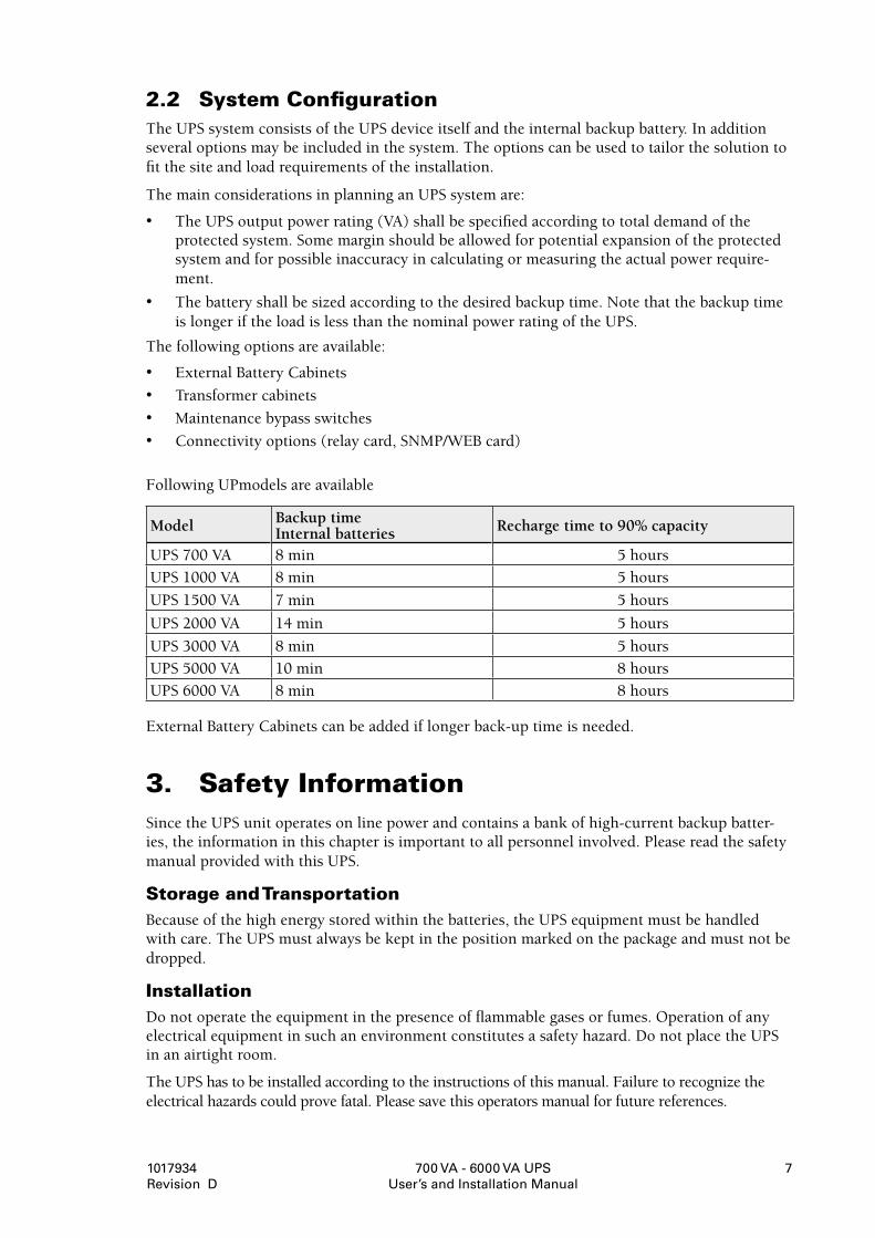
Following UPmodels are available
External Battery Cabinets can be added if longer back-up time is needed.
3. SafetyInformationSince the UPS unit operates on line power and contains a bank of high-current backup batter-ies, the information in this chapter is important to all personnel involved. Please read the safety manual provided with this UPS.
StorageandTransportationBecause of the high energy stored within the batteries, the UPS equipment must be handled with care. The UPS must always be kept in the position marked on the package and must not be dropped.
InstallationDo not operate the equipment in the presence of flammable gases or fumes. Operation of any electrical equipment in such an environment constitutes a safety hazard. Do not place the UPS in an airtight room.
The UPS has to be installed according to the instructions of this manual. Failure to recognize the electrical hazards could prove fatal. Please save this operators manual for future references.
Model Backup time Internal batteries Recharge time to 90% capacity
UPS 700 VA 8 min 5 hours
UPS 1000 VA 8 min 5 hours
UPS 1500 VA 7 min 5 hours
UPS 2000 VA 14 min 5 hours
UPS 3000 VA 8 min 5 hours
UPS 5000 VA 10 min8hours 8 hours
UPS 6000 VA 8 min 8 hours
700 VA - 6000 VA UPS User’s and Installation Manual
1017934 Revision D
�
WARNING!
Do not open the UPS cabinet. Some components inside the UPS cabinet carry high volt-age. To touch them may prove fatal. All operations inside the unit must be carried out only by a service engineer from the manufacturer or from an agent authorized by the manufacturer. This UPS contains its own energy source (batteries). The output receptacles may carry live voltage even when the UPS is not connected to an AC supply.
User’soperations
The only users operations permitted are :
• Starting up and shutting down the UPS unit
• Operating the users interface
• Connecting data interface cables
• Replacing batteries
These operations must be performed according to the instructions in this manual. During any of these operations the user must take greatest care and perform only the prescribed operations. Any deviation from the instructions could be dangerous to the operator.
4.StorageandUnpacking
4.1StorageIf the UPS is not immediately installed the following has to be remembered.
• The equipment should be stored in the original packing and shipping cartoon.
• The recommended storing temperature is between +15°C ... +25°C.
• The equipment have to be always protected from moisture.
If the UPS is stored for a longer period of time the batteries of the UPS should be charged for at least 8 hours every 6 months to maintain the battery condition.
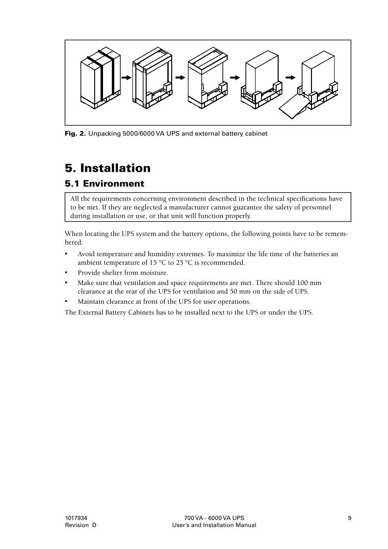
4.2UnpackingUnpack the equipment and remove all the packing materials and shipping cartoon. (See fig. 2. for unpacking 5000 & 6000 VA UPS and External battery cabinets for 5000 & 6000 VA)
Note! Do not lift the UPS or External Battery Cabinets from the front panel.
The equipment have to be inspected for damage during shipment. If damage has occurred dur-ing transit, all the shipping cartoons and packing materials should be stored for further investi-gation. If the damage is visible a claim for shipping damage have to be filled immediately.
To file a claim for shipping damage:
• The carrier has to be informed within 7 days of receipt of the equipment.
• The equipment has to be checked against the packing slip to verify that the shipment is complete.
700 VA - 6000 VA UPS User’s and Installation Manual
1017934 Revision D
9
Fig.2.Unpacking �000/6000 VA UPS and external battery cabinet
5.Installation5.1Environment
All the requirements concerning environment described in the technical specifications have to be met. If they are neglected a manufacturer cannot guarantee the safety of personnel during installation or use, or that unit will function properly.
When locating the UPS system and the battery options, the following points have to be remem-bered:
• Avoid temperature and humidity extremes. To maximize the life time of the batteries an ambient temperature of 15 °C to 25 °C is recommended.
• Provide shelter from moisture.
• Make sure that ventilation and space requirements are met. There should 100 mm clearance at the rear of the UPS for ventilation and 50 mm on the side of UPS.
• Maintain clearance at front of the UPS for user operations.
The External Battery Cabinets has to be installed next to the UPS or under the UPS.
700 VA - 6000 VA UPS User’s and Installation Manual
1017934 Revision D
10
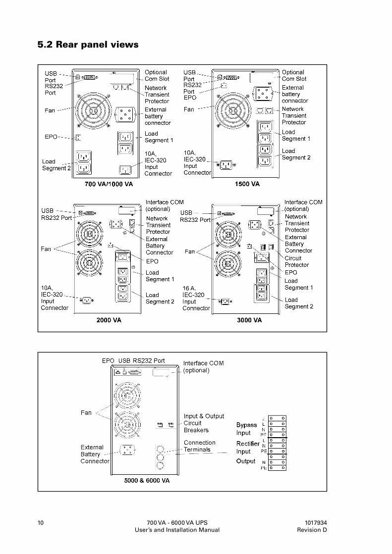
5.2Rearpanelviews
700 VA - 6000 VA UPS User’s and Installation Manual
1017934 Revision D
11
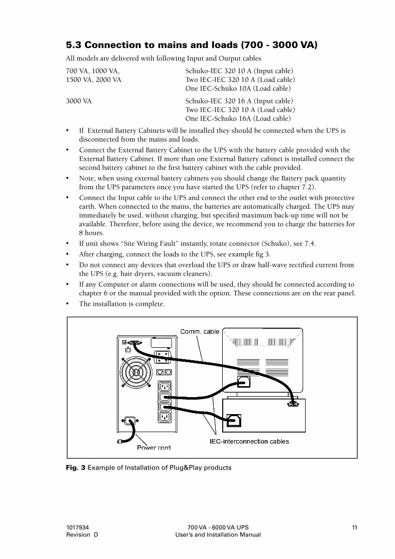
5.3Connectiontomainsandloads(700-3000VA)All models are delivered with following Input and Output cables
700 VA, 1000 VA, Schuko-IEC 320 10 A (Input cable) 1500 VA, 2000 VA Two IEC-IEC 320 10 A (Load cable) One IEC-Schuko 10A (Load cable)
3000 VA Schuko-IEC 320 16 A (Input cable) Two IEC-IEC 320 10 A (Load cable) One IEC-Schuko 16A (Load cable)
• If External Battery Cabinets will be installed they should be connected when the UPS is disconnected from the mains and loads.
• Connect the External Battery Cabinet to the UPS with the battery cable provided with the External Battery Cabinet. If more than one External Battery cabinet is installed connect the second battery cabinet to the first battery cabinet with the cable provided.
• Note, when using external battery cabinets you should change the Battery pack quantity from the UPS parameters once you have started the UPS (refer to chapter 7.2).
• Connect the Input cable to the UPS and connect the other end to the outlet with protective earth. When connected to the mains, the batteries are automatically charged. The UPS may immediately be used, without charging, but specified maximum back-up time will not be available. Therefore, before using the device, we recommend you to charge the batteries for 8 hours.
• If unit shows “Site Wiring Fault” instantly, rotate connector (Schuko), see 7.4.
• After charging, connect the loads to the UPS, see example fig 3.
• Do not connect any devices that overload the UPS or draw half-wave rectified current from the UPS (e.g. hair dryers, vacuum cleaners).
• If any Computer or alarm connections will be used, they should be connected according to chapter 6 or the manual provided with the option. These connections are on the rear panel.
• The installation is complete.
Fig.3Example of Installation of Plug&Play products
700 VA - 6000 VA UPS User’s and Installation Manual
1017934 Revision D
12
5.4Connectiontomainsandloads5000-6000VAOnly qualified specialists in conformity with the applicable safety standards must carry out the installation. The installation must comply with all local legislation and regulations.
Installation instructions must be carefully followed. If they are neglected, the safety of the personnel involved is threatened and the UPS or the load connections to the UPS can be damaged.
The UPS contains high voltage and current which can injure or kill personnel and damage equipment.
For electrical installation, the nominal current rating of the source must be observed.
Installing External battery cabinets
• If External Battery Cabinets will be installed they should be connected when the UPS is disconnected from the mains and loads.
• Connect the External Battery Cabinet to the UPS with the battery cable provided with the External Battery Cabinet. If more than one External Battery cabinet is installed connect the second battery cabinet to the first battery cabinet with the cable provided.
• Note, when using external battery cabinets you should change the Battery pack quantity from the UPS parameters once you have started the UPS (refer to chapter 7.2).
Installing UPS
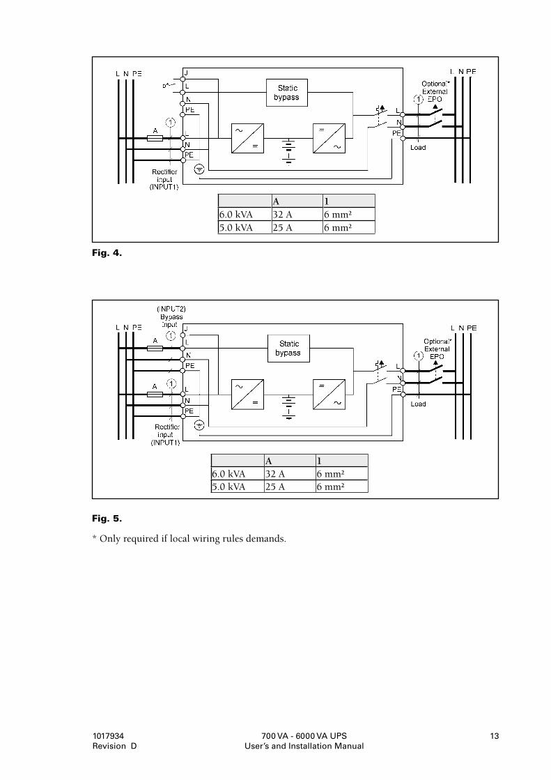
• Check that electrical connections to the installation site have been properly executed. Also check the fuse and cable dimensions against figure 4 and figure 5.
• The source must be isolated and secured against reclosing. The circuit breakers (both Input and Output circuit breaker) located at the rear panel must be in position “OFF”.
• Connect the UPS according to following connection diagram see fig. 4 for single cable input and fig. 5 for two cable input. If two cable installation is considerad the interconnection jumper (b*) needs to be removed. (See fig. 4). Select fuses and cable sizes from the table fig.5.
• In installation where neutral is not grounded or when it is not possible to rely on the identification of the neutral in the mains supply, it is necessary to provide an additional two pole disconnect device in the building installation.
• Emergency Power Off (EPO) input is located in the rear of the unit. When this connection is open, the logic circuit will immediately shut down the output of the UPS, see fig. 4 and 5. Wiring the EPO signal is optional.
• Note! If local safety requirement requires an separate external Emergency power Off that opens the output circuit breakers it shoud be installed as shown in fig. 4 and fig. 5. Refer to local wiring rules.
• If any Computer or alarm connections will be used, they should be connected according to chapter 6 or the manual provided with the option. These connections are on the rear panel.
• The installation is complete.
b*) removable jumper when dual input used
700 VA - 6000 VA UPS User’s and Installation Manual
1017934 Revision D
13
Fig.4.
Fig.5.
* Only required if local wiring rules demands.
A 16.0 kVA 32 A 6 mm²5.0 kVA 25 A 6 mm²
A 16.0 kVA 32 A 6 mm²5.0 kVA 25 A 6 mm²
700 VA - 6000 VA UPS User’s and Installation Manual
1017934 Revision D
14
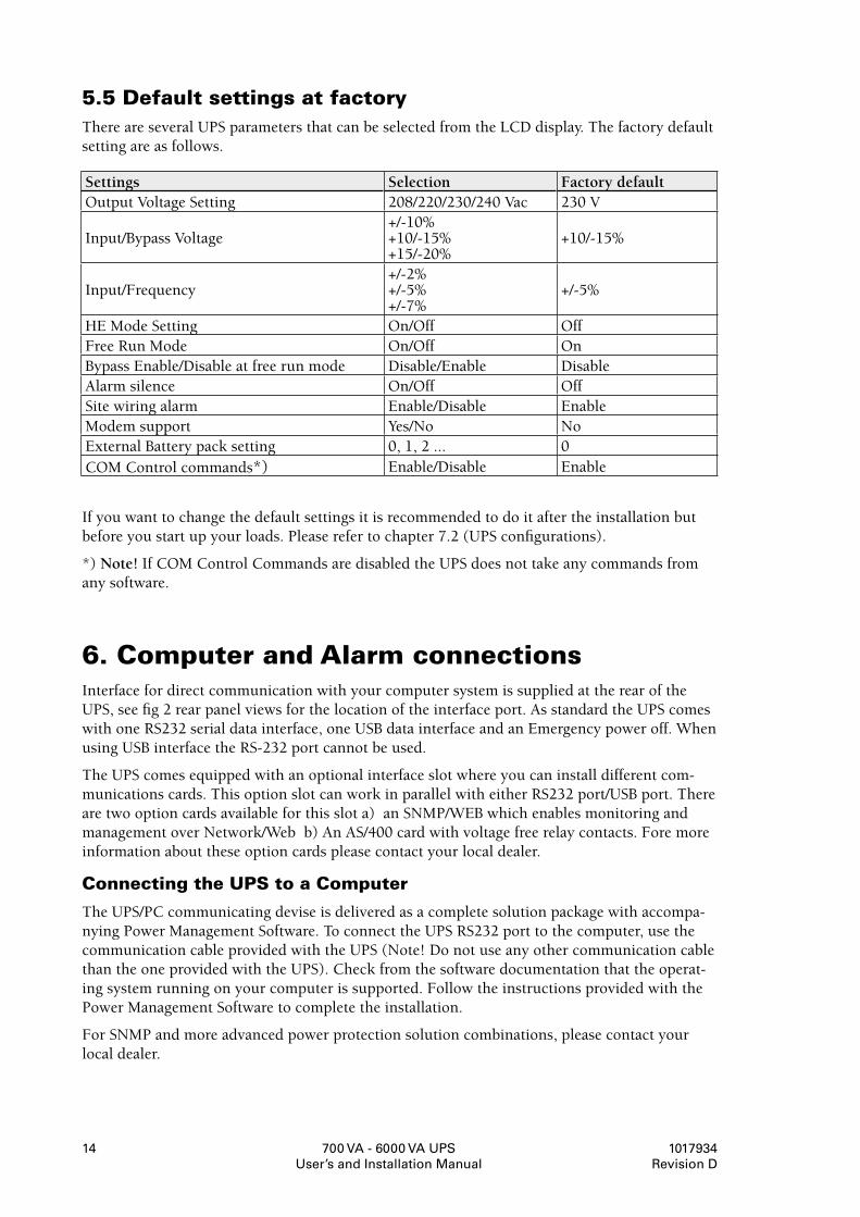
5.5DefaultsettingsatfactoryThere are several UPS parameters that can be selected from the LCD display. The factory default setting are as follows.
If you want to change the default settings it is recommended to do it after the installation but before you start up your loads. Please refer to chapter 7.2 (UPS configurations).
*) Note! If COM Control Commands are disabled the UPS does not take any commands from any software.
6.ComputerandAlarmconnectionsInterface for direct communication with your computer system is supplied at the rear of the UPS, see fig 2 rear panel views for the location of the interface port. As standard the UPS comes with one RS232 serial data interface, one USB data interface and an Emergency power off. When using USB interface the RS-232 port cannot be used.
The UPS comes equipped with an optional interface slot where you can install different com-munications cards. This option slot can work in parallel with either RS232 port/USB port. There are two option cards available for this slot a) an SNMP/WEB which enables monitoring and management over Network/Web b) An AS/400 card with voltage free relay contacts. Fore more information about these option cards please contact your local dealer.
ConnectingtheUPStoaComputer
The UPS/PC communicating devise is delivered as a complete solution package with accompa-nying Power Management Software. To connect the UPS RS232 port to the computer, use the communication cable provided with the UPS (Note! Do not use any other communication cable than the one provided with the UPS). Check from the software documentation that the operat-ing system running on your computer is supported. Follow the instructions provided with the Power Management Software to complete the installation.
For SNMP and more advanced power protection solution combinations, please contact your local dealer.
Settings Selection Factory defaultOutput Voltage Setting 208/220/230/240 Vac 230 V
Input/Bypass Voltage+/-10% +10/-15% +15/-20%
+10/-15%
Input/Frequency+/-2% +/-5% +/-7%
+/-5%
HE Mode Setting On/Off OffFree Run Mode On/Off OnBypass Enable/Disable at free run mode Disable/Enable DisableAlarm silence On/Off OffSite wiring alarm Enable/Disable EnableModem support Yes/No NoExternal Battery pack setting 0, 1, 2 ... 0COM Control commands*) Enable/Disable Enable
700 VA - 6000 VA UPS User’s and Installation Manual
1017934 Revision D
1�
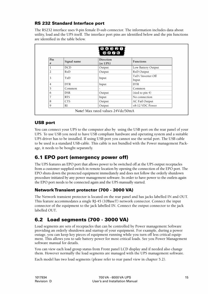
RS232StandardInterfaceportThe RS232 interface uses 9-pin female D-sub connector. The information includes data about utility, load and the UPS itself. The interface port pins are identified below and the pin functions are identified in the table below.
USBport
You can connect your UPS to the computer also by using the USB port on the rear panel of your UPS. To use USB you need to have USB compliant hardware and operating system and a suitable UPS driver has to be installed. If using USB port you cannot use the serial port. The USB cable to be used is a standard USB-cable. This cable is not bundled with the Power management Pack-age, it needs to be bought separately.
6.1EPOport(emergencypoweroff)The UPS features an EPO port that allows power to be switched off at the UPS output receptacles from a customer supplied switch in remote location by opening the connection of the EPO port. The EPO shuts down the protected equipment immediately and does not follow the orderly shutdown procedure initiated by any power management software. In order to have power to the outlets again the EPO port needs to be connected again and the UPS manually started.
NetworkTransientprotector(700-3000VA)The Network transient protector is located on the rear panel and has jacks labelled IN and OUT. This feature accommodates a single RJ-45 (10BaseT) network connector. Connect the input connector of the equipment to the jack labelled IN. Connect the output connector to the jack labelled OUT.
6.2 Loadsegments(700-3000VA)Load segments are sets of receptacles that can be controlled by Power management Software providing an orderly shutdown and startup of your equipment. For example, during a power outage, you can keep key pieces of equipment running while you turn off less critical equip-ment. This allows you to safe battery power for most critical loads. See you Power Management software manual for details.
You can view each load group status from Front panel LCD display and if needed also change them. However normally the load segments are managed with the UPS management software.
Each model has two load segments (please refer to rear panel view in chapter 5.2).
Note! Max rated values 24Vdc/50mA
Pin #
Signal nameDirection (re UPS)
Functions
1 DCD Output Low Battery Output2 RxD Output RxD Output
3 TxD InputTxD / Inverter Off Input
4 DTR Input DTR5 Common - Common6 DSR Output (tied to pin 4)7 RTS Input No connection8 CTS Output AC Fail Output9 RI Output +8-12 VDC Power
700 VA - 6000 VA UPS User’s and Installation Manual
1017934 Revision D
16
7. User’sguidetooperationsThis chapter contains the necessary information on how to use the UPS. Starting and stopping an UPS are operations that are rarely carried out (for example, only when it is initially brought into service or when there is a long-term disconnection from the mains). This UPS is essentially designed for permanent operation.
The front panel is equipped with 3 buttons:
Start/Stop button for the UPS
Input button: for selecting a setting/option or registering the setting.
Scroll button: for accessing the Configuration mode or scrolling through the options.
7.1 StartingandshuttingdowntheUPS
Starting the UPS
• Ensure that it has been properly installed and that the power cord has been plugged into a socket that has been earthed.
• To start the UPS, push the button on the front panel.• The UPS performs a self-test, installs in the mains and feeds its output sockets. • During the self-test, the screen displays “On delay”. Once the UPS output becomes active,
the screen displays “On line” and the indicators light up.• Switch on the protective equipment (for the electric charge).
Shutting down the UPS
• Switch off the electrical charge.• Hold the button for 5 seconds. When the alarm beeps, the UPS will stop. • The screen displays “UPS OFF” for a few seconds.• In the case of an emergency, use the emergency power off button (EPO) on the rear panel of
the apparatus.
700 VA - 6000 VA UPS User’s and Installation Manual
1017934 Revision D
17
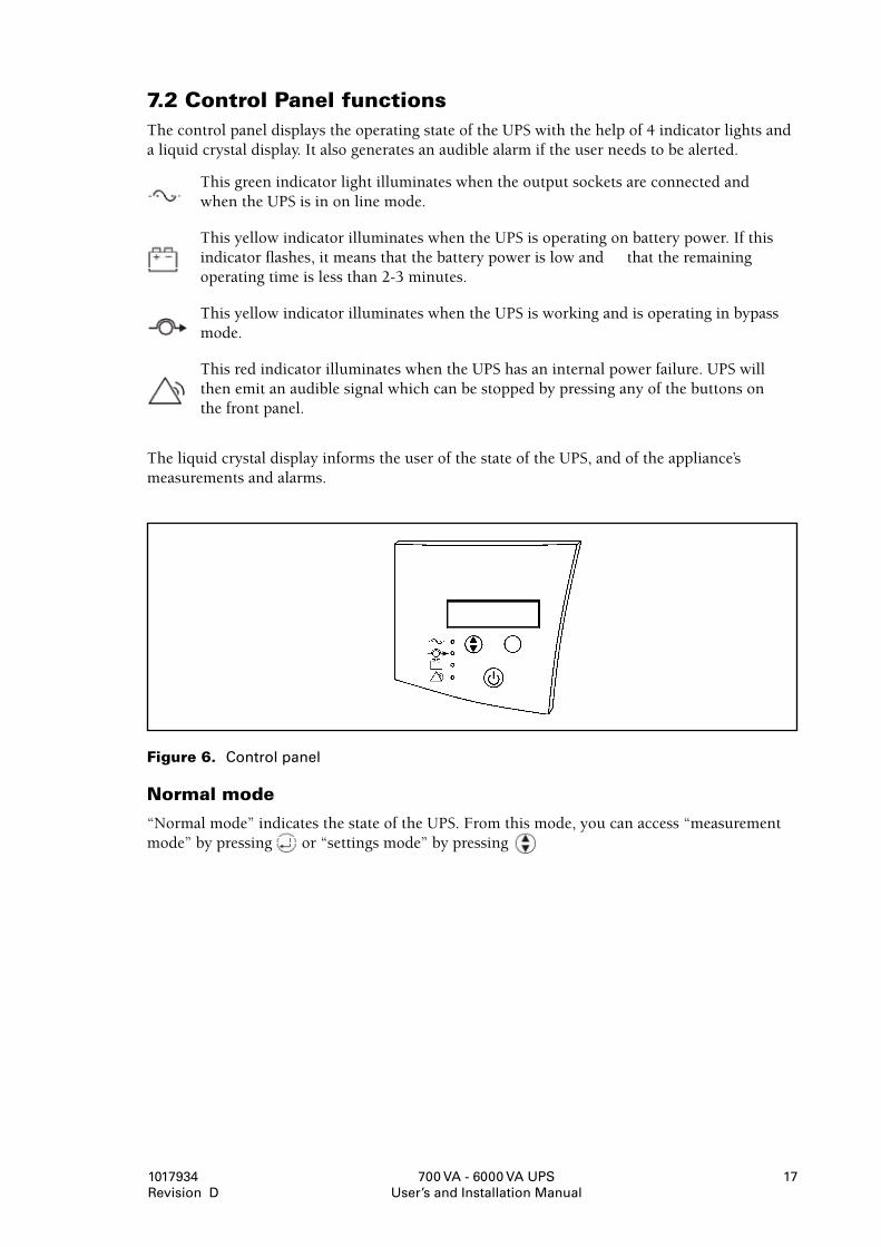
7.2ControlPanelfunctionsThe control panel displays the operating state of the UPS with the help of 4 indicator lights and a liquid crystal display. It also generates an audible alarm if the user needs to be alerted.
This green indicator light illuminates when the output sockets are connected and when the UPS is in on line mode.
This yellow indicator illuminates when the UPS is operating on battery power. If this indicator flashes, it means that the battery power is low and that the remaining operating time is less than 2-3 minutes.
This yellow indicator illuminates when the UPS is working and is operating in bypass mode.
This red indicator illuminates when the UPS has an internal power failure. UPS will then emit an audible signal which can be stopped by pressing any of the buttons on the front panel.
The liquid crystal display informs the user of the state of the UPS, and of the appliance’s measurements and alarms.
Figure6.Control panel
Normalmode
“Normal mode” indicates the state of the UPS. From this mode, you can access “measurement mode” by pressing or “settings mode” by pressing .
700 VA - 6000 VA UPS User’s and Installation Manual
1017934 Revision D
1�
UPSmetersdisplay
The screen informs the user of the various measurements which can be carried out by the UPS. By pressing the button, you can scroll through the measurements settings. To view a setting continually, hold the button for 3 seconds. Press the same button to switch to another setting.
The following measurements are available:
*) Can be different from Input Voltage when using dual input.
UPSconfigurations
1. Hold the button for 1 second to activate the Configuration mode. The screen displays the first configuration setting (see table 1.).
2. Press the button to scroll through the settings.
3. Hold to select the displayed setting.
4. Press to scroll through the different possible options for this setting. Press to select the displayed option.
A message may invite you to register your selection. To do this, press . Other options are saved automatically (see table 1).
5. To quit Configuration mode at any time, all you have to do is hold any button for 5 seconds. The UPS will automatically revert back to online mode.
Note!
It is not usually necessary to modify the factory settings. However, doing so allows you to customise your UPS to meet your specific needs.
LCD message Description
I/P VOL T= xxx,xV Indicates the value of the input voltageBypass Voltage Bypass source voltage (only on 5000 and 6000 VA models)I/P FREQ=xx,x Hz Input frequencyO/P VOLT= xxx,xV Output voltageO/P FREQ=xx,x Hz Output frequencyO/P LOAD %= xxx% Percentage power of UPS usedO/P Watt=xW Output power (in W)O/P VA= xVA Output power (VA)O/P CUR= xxA Output currentBAT VOLT=xx,xV Battery voltageBAT CHARG=xxx% Percentage of battery power remaining
BACKUP TIME=xxx minBattery power remaining (in minutes). The measurement is indi-cated in seconds to within a minute. (Backup Time=xxxS)
CPU Version x.xx Revision index of the internal software.
700 VA - 6000 VA UPS User’s and Installation Manual
1017934 Revision D
19
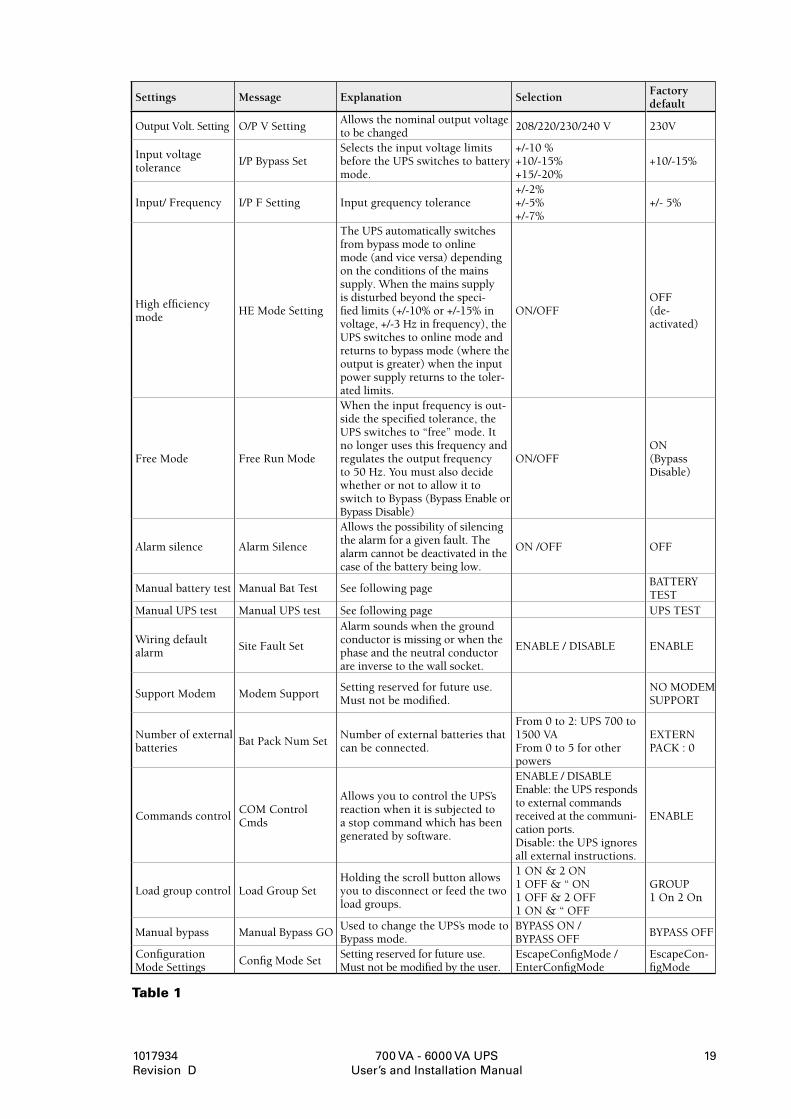
Table1
Settings Message Explanation SelectionFactory default
Output Volt. Setting O/P V SettingAllows the nominal output voltage to be changed
208/220/230/240 V 230V
Input voltage tolerance
I/P Bypass SetSelects the input voltage limits before the UPS switches to battery mode.
+/-10 % +10/-15% +15/-20%
+10/-15%
Input/ Frequency I/P F Setting Input grequency tolerance+/-2% +/-5% +/-7%
+/- 5%
High efficiency mode
HE Mode Setting
The UPS automatically switches from bypass mode to online mode (and vice versa) depending on the conditions of the mains supply. When the mains supply is disturbed beyond the speci-fied limits (+/-10% or +/-15% in voltage, +/-3 Hz in frequency), the UPS switches to online mode and returns to bypass mode (where the output is greater) when the input power supply returns to the toler-ated limits.
ON/OFFOFF (de- activated)
Free Mode Free Run Mode
When the input frequency is out-side the specified tolerance, the UPS switches to “free” mode. It no longer uses this frequency and regulates the output frequency to 50 Hz. You must also decide whether or not to allow it to switch to Bypass (Bypass Enable or Bypass Disable)
ON/OFFON (Bypass Disable)
Alarm silence Alarm Silence
Allows the possibility of silencing the alarm for a given fault. The alarm cannot be deactivated in the case of the battery being low.
ON /OFF OFF
Manual battery test Manual Bat Test See following pageBATTERY TEST
Manual UPS test Manual UPS test See following page UPS TEST
Wiring default alarm
Site Fault Set
Alarm sounds when the ground conductor is missing or when the phase and the neutral conductor are inverse to the wall socket.
ENABLE / DISABLE ENABLE
Support Modem Modem SupportSetting reserved for future use. Must not be modified.
NO MODEM SUPPORT
Number of external batteries
Bat Pack Num SetNumber of external batteries that can be connected.
From 0 to 2: UPS 700 to 1500 VA From 0 to 5 for other powers
EXTERN PACK : 0
Commands controlCOM Control Cmds
Allows you to control the UPS’s reaction when it is subjected to a stop command which has been generated by software.
ENABLE / DISABLE Enable: the UPS responds to external commands received at the communi-cation ports. Disable: the UPS ignores all external instructions.
ENABLE
Load group control Load Group SetHolding the scroll button allows you to disconnect or feed the two load groups.
1 ON & 2 ON 1 OFF & “ ON 1 OFF & 2 OFF 1 ON & “ OFF
GROUP 1 On 2 On
Manual bypass Manual Bypass GOUsed to change the UPS’s mode to Bypass mode.
BYPASS ON / BYPASS OFF
BYPASS OFF
Configuration Mode Settings
Config Mode SetSetting reserved for future use. Must not be modified by the user.
EscapeConfigMode / EnterConfigMode
EscapeCon-figMode
700 VA - 6000 VA UPS User’s and Installation Manual
1017934 Revision D
20
ManualtestoftheUPS
From UPS configuration you can also do Manual UPS test or Manual Battery test. These tests are functional when the UPS is not in battery charging mode.
Manual Battery test: Scroll the parameters until Manual Bat test displays on the LCD. Press the button twice.
Manual UPS test: Scroll the parameters until Manual UPS test displays on the LCD. Press the button twice.
*) If disable is chosen UPS does not take commands from any management software. For exam-ple a shutdown of the UPS issued by power management software to boot a computer will not be carried out.
**) Note: To have the UPS and power management software operate normally, the setting must always be Manual Bypass OFF. The unit will not protect the load when Manual Bypass is ON. This mode is intended to be used when operating an external maintenance bypass switch, if installed.
7.3 InterpretingUPSmessagesShould a malfunction occur in the UPS, the trouble shooting procedure gives simple remedial instructions.
Operator should start the trouble shooting if there is an active alarm indicated on the control panel.
Alarmindicators
The UPS gives the following audible alarms:
• UPS is on battery and the ON BATTERY LED is on :UPS beeps every 4 second.
• Battery capacity low and the ON BATTERY LED is flashing: UPS beeps every second.
• UPS on bypass and the BYPASSED LED is on: UPS beeps every second.
• UPS has internal fault and the ALARM LED is on : UPS gives an constant audible alarm and displays the cause of the alarm on the LCD.
Silencinganalarm
You can silence any audible alarm by pressing any of the three buttons once the audible alarm sounds. When UPS gives “battery low” alarm the audible alarm starts again.
You can also choose silence alarm from the LCD display. This does that no audible alarm is given at all.
700 VA - 6000 VA UPS User’s and Installation Manual
1017934 Revision D
21
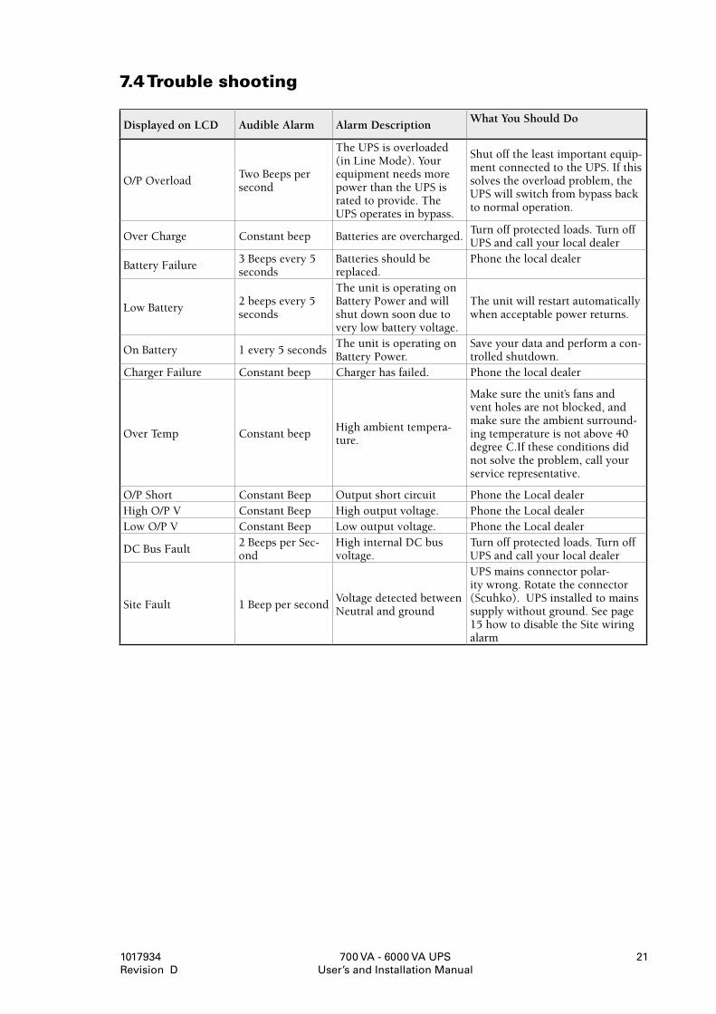
7.4Troubleshooting
Displayed on LCD Audible Alarm Alarm DescriptionWhat You Should Do
O/P OverloadTwo Beeps per second
The UPS is overloaded (in Line Mode). Your equipment needs more power than the UPS is rated to provide. The UPS operates in bypass.
Shut off the least important equip-ment connected to the UPS. If this solves the overload problem, the UPS will switch from bypass back to normal operation.
Over Charge Constant beep Batteries are overcharged.Turn off protected loads. Turn off UPS and call your local dealer
Battery Failure3 Beeps every 5 seconds
Batteries should be replaced.
Phone the local dealer
Low Battery2 beeps every 5 seconds
The unit is operating on Battery Power and will shut down soon due to very low battery voltage.
The unit will restart automatically when acceptable power returns.
On Battery 1 every 5 secondsThe unit is operating on Battery Power.
Save your data and perform a con-trolled shutdown.
Charger Failure Constant beep Charger has failed. Phone the local dealer
Over Temp Constant beepHigh ambient tempera-ture.
Make sure the unit’s fans and vent holes are not blocked, and make sure the ambient surround-ing temperature is not above 40 degree C.If these conditions did not solve the problem, call your service representative.
O/P Short Constant Beep Output short circuit Phone the Local dealerHigh O/P V Constant Beep High output voltage. Phone the Local dealerLow O/P V Constant Beep Low output voltage. Phone the Local dealer
DC Bus Fault2 Beeps per Sec-ond
High internal DC bus voltage.
Turn off protected loads. Turn off UPS and call your local dealer
Site Fault 1 Beep per secondVoltage detected between Neutral and ground
UPS mains connector polar-ity wrong. Rotate the connector (Scuhko). UPS installed to mains supply without ground. See page 15 how to disable the Site wiring alarm
700 VA - 6000 VA UPS User’s and Installation Manual
1017934 Revision D
22
8.MaintenanceThe UPS can be expected to have a long and trouble-free life with a minimum preventive main-tenance. Environmental issues are the most critical in determining the reliability of UPS and batteries. The temperature and the humidity have to be within specifications. The area around the unit should be kept relatively clean and dust free.
The typical battery lifetime is 4 years at an ambient temperature of 25 °C.
Check in periodical intervals (6 to 12 months) whether the battery back-up time of the UPS is still sufficient for its applications. If not the batteries have to be replaced.
8.1ReplacingbatteriesThe hot–swappable battery feature allows you to replace the UPS batteries without turning the UPS off or disconnecting the load.
WARNING!
Batteries can present a risk of electrical shock or burn from high short circuit current. The following precautions should be observed: 1. Remove watches, rings or other metal objects. 2. Use tools with insulated handles. 3. Do not lay tools or metal parts on top of batteries.
ELECTRIC ENERGY HAZARD. Do not attempt to alter any battery wiring or connectors. Attempting to alter wiring can cause injury.
Replace the batteries with the same number and type as originally installed batteries.
DO NOT DISCONNECT the batteries while UPS is in Battery mode.
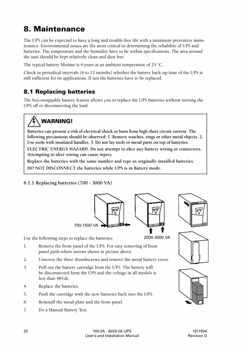
8.1.1 Replacing batteries (700 - 3000 VA)
Use the following steps to replace the batteries:
1. Remove the front panel of the UPS. For easy removing of front panel push where arrows shows in picture above.
2. Unscrew the three thumbscrews and remove the metal battery cover.
3. Pull out the battery cartridge from the UPS. The battery will be disconnected form the UPS and the voltage in all models is less than 48Vdc.
4. Replace the batteries.
5. Push the cartridge with the new batteries back into the UPS.
6. Reinstall the metal plate and the front panel.
7. Do a Manual Battery Test.
700-1500 VA
2000-3000 VA
700 VA - 6000 VA UPS User’s and Installation Manual
1017934 Revision D
23
8.1.2. Replacing batteries (5000 - 6000 VA)
The hot–swappable battery feature allows replacement of the UPS batteries without turning the UPS off or disconnecting the load.
However the battery replacement need to be done by qualified people. The UPS own battery monitoring system will inform you well in advance when batteries needs to be replaced and gives an alarm.
8.2ServiceBypassOptionThis option can be installed with your UPS to bypass the UPS during service or maintenance. For installation of the Bypass option please read the separate manual that comes with the bypass cabinet.
NOTE! For battery replacement you do not need the bypass option, since PW9120 batteries are hot swappable
UsingtheMechanicalBypass
Before switching the Mechanical bypass to bypass position you have to force the UPS to internal bypass to ensure the unit and the mains are synchronized. This can be done by selecting “Manual bypass” from UPS settings in the LCD menu (see UPS configurations page 19). After this you may switch the Mechanical Bypass to bypass position and this will not cause any break in the output voltage to the load.
700 VA - 6000 VA UPS User’s and Installation Manual
1017934 Revision D
24
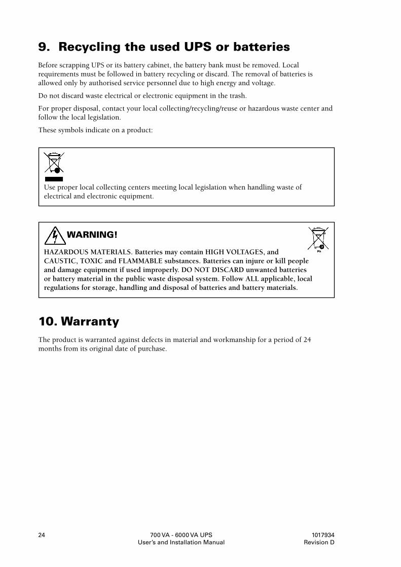
9.RecyclingtheusedUPSorbatteriesBefore scrapping UPS or its battery cabinet, the battery bank must be removed. Local requirements must be followed in battery recycling or discard. The removal of batteries is allowed only by authorised service personnel due to high energy and voltage.
Do not discard waste electrical or electronic equipment in the trash.
For proper disposal, contact your local collecting/recycling/reuse or hazardous waste center and follow the local legislation.
These symbols indicate on a product:
Use proper local collecting centers meeting local legislation when handling waste of electrical and electronic equipment.
WARNING!
HAZARDOUS MATERIALS. Batteries may contain HIGH VOLTAGES, and CAUSTIC, TOXIC and FLAMMABLE substances. Batteries can injure or kill people and damage equipment if used improperly. DO NOT DISCARD unwanted batteries or battery material in the public waste disposal system. Follow ALL applicable, local regulations for storage, handling and disposal of batteries and battery materials.
10.WarrantyThe product is warranted against defects in material and workmanship for a period of 24 months from its original date of purchase.
700 VA - 6000 VA UPS User’s and Installation Manual
1017934 Revision D
2�
11.TechnicalSpecifications
11.1PowerRange700-3000VA
GENERAL
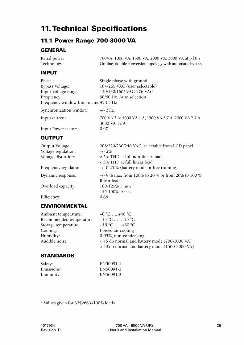
Rated power 700VA, 1000 VA, 1500 VA, 2000 VA, 3000 VA at p.f 0,7 Technology On-line, double conversion topology with automatic bypass
INPUT
Phase : Single phase with ground Bypass Voltage: 184-265 VAC (user selectable) Input Voltage range: 120/140/160 1 VAC-276 VAC Frequency: 50/60 Hz. Auto selection Frequency window from mains 45-65 Hz
Synchronization window +/- 3Hz.
Input current 700 VA 3 A; 1000 VA 4 A, 1500 VA 5,7 A, 2000 VA 7,7 A 3000 VA 12 A Input Power factor: 0,97
OUTPUT
Output Voltage : 208/220/230/240 VAC, selectable from LCD panel Voltage regulation: +/- 2% Voltage distortion: < 5% THD at full non-linear load, < 3% THD at full linear load Frequency regulation +/- 0,25 % (battery mode or free running)
Dynamic response: +/- 9 % max from 100% to 20 % or from 20% to 100 % linear load Overload capacity: 100-125% 1 min 125-150% 10 sec Efficiency: 0,86
ENVIRONMENTAL
Ambient temperature: +0 °C…...+40 °C Recommended temperature: +15 °C …...+25 °C Storage temperature: - 15 °C …...+50 °C Cooling: Forced air cooling Humidity: 0-95%, non-condensing Audible noise: < 45 db normal and battery mode (700-1000 VA) < 50 db normal and battery mode (1500-3000 VA)
STANDARDS
Safety: EN50091-1-1 Emissions: EN50091-2 Immunity: EN50091-2
1 Values given for 33%/66%/100% loads

700 VA - 6000 VA UPS User’s and Installation Manual
1017934 Revision D
26
11.2PowerRange5000-6000VA
GENERAL
Rated power 5000 VA, 6000 VA at p.f 0,7 Technology On-line, double conversion topology with automatic bypass
INPUT
Phase : Single phase with ground Bypass Voltage: 180-265 VAC (user selectable) Input Voltage range: 120/140/160/184* _ 276 VAC Frequency: 50/60 Hz. Auto selection Frequency window from mains 45-65 Hz
Synchronization window +/- 3Hz.
Input current 5000 VA 25 A 6000 VA 30 A Input Power factor: 0,97
*) 120 V at 25% load, 140 V at 50% load, 160 V at 25% load, 184 at 100% load
OUTPUT POWER
700VA/490W 1000VA/700W 1500VA/1050W 2000VA/1400W 3000VA/2100W
Connection Input
IEC 320 (10 A) IEC 320 (10 A) IEC 320 (10 A) IEC 320 (10 A) IEC 320 (16 A)
Connection Output
4*IEC 320 (10 A)
4*IEC 320 (10 A)
4*IEC 320 (10 A)
4*IEC 320 (10 A) (IEC 320 16A)
1*IEC 320 (16 A) (4 IEC 320 10A)
Battery typeLead-acid 9 Ah/12 V
Lead-acid 9 Ah/12 V
Lead-acid 9 Ah/12 V
Lead-acid 9 Ah/12 V
Lead-acid 9 Ah/12 V
Number of batteries
2 3 4 8 8
Backup time/full load
8 min 8 min 7 min 14 min 8 min
Recharge time
<5 hours to 90% <5 hours to 90% <5 hours to 90% <5 hours to 90% <5 hours to 90%
Dimensions W*D*H mm
155*410*245 155*410*245 170*445*275 225*470*365 225*470*365
Weight kg 13 15 20 37 38
Battery Cabinets 700 VA 1000 VA 1500 VA 2000 VA 3000 VA
Battery typeLead-acid 9 Ah/12 V
Lead-acid 9 Ah/12 V
Lead-acid 9 Ah/12 V
Lead-acid 9 Ah/12 V
Lead-acid 9 Ah/12 V
Number of bat-teries
4 6 8 16 16
Backup time/full load
Approx. 30 min Approx. 30 min Approx. 30 min Approx. 30 min Approx. 30 min
Recharge time <16 h to 90 % <16 h to 90 % <16 h to 90 % <16 h to 90 % <16 h to 90 %
Dimensions W*D*H mm
155*410*245 155*410*245 170*445*275 225*470*365 225*470*365
Weight kg 15 20 25 50 50
700 VA - 6000 VA UPS User’s and Installation Manual
1017934 Revision D
27
OUTPUT
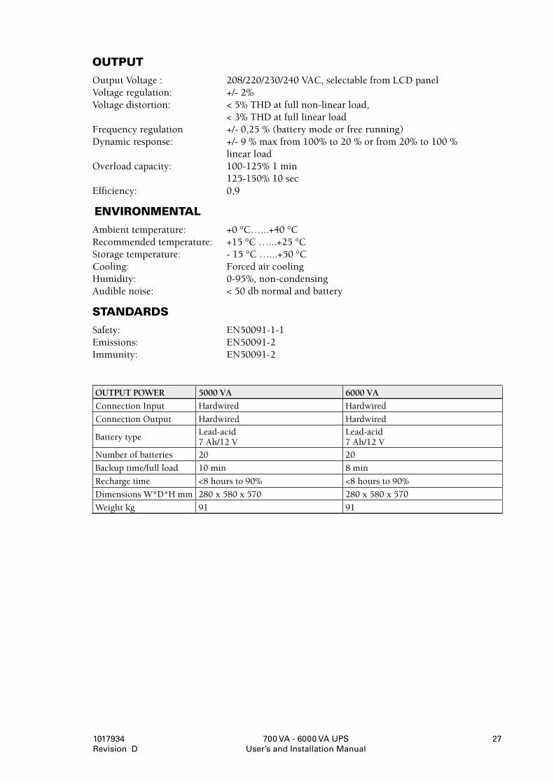
Output Voltage : 208/220/230/240 VAC, selectable from LCD panel Voltage regulation: +/- 2% Voltage distortion: < 5% THD at full non-linear load, < 3% THD at full linear load Frequency regulation +/- 0,25 % (battery mode or free running) Dynamic response: +/- 9 % max from 100% to 20 % or from 20% to 100 % linear load Overload capacity: 100-125% 1 min 125-150% 10 sec Efficiency: 0,9
ENVIRONMENTAL
Ambient temperature: +0 °C…...+40 °C Recommended temperature: +15 °C …...+25 °C Storage temperature: - 15 °C …...+50 °C Cooling: Forced air cooling Humidity: 0-95%, non-condensing Audible noise: < 50 db normal and battery
STANDARDS
Safety: EN50091-1-1 Emissions: EN50091-2 Immunity: EN50091-2
OUTPUT POWER 5000 VA 6000 VA
Connection Input Hardwired Hardwired
Connection Output Hardwired Hardwired
Battery typeLead-acid 7 Ah/12 V
Lead-acid 7 Ah/12 V
Number of batteries 20 20
Backup time/full load 10 min 8 min
Recharge time <8 hours to 90% <8 hours to 90%
Dimensions W*D*H mm 280 x 580 x 570 280 x 580 x 570
Weight kg 91 91
