70275 revised aluminum cargo carrier -v1 manual 20130323
TRANSCRIPT

Read and understand this entire manual before assembling, installing, operating, or servicing this product.
SAVE THIS MANUAL
Instruction Manual & Parts Catalog
Aluminum Cargo Carrier with 60” Long Ramp
Model 70275
Rev 05/12
TM
Copyrightc 2012 by PGS, LLC.. All rights reserved. No portion of this manual or any artwork contained herein may be reproduced in any shape or form without the express written consent of PGS, LLC. Due to continuing improvements, actual product may differ slightly from the product described herein. Tools required for assembly and maintenance may not be included.

IMPORTANT SAFETYINFORMATION
This is a SAFETY ALERT symbol. It is used to alert you to potential personal injury hazards.Obey all safety messages that follow this symbol to avoid possible injury or death.
DANGER indicates a hazardous situation which, if not avoided, will result in death or injury.
WARNING indicates a hazardous situation which, if not avoided, could result in death or serious injury.
CAUTION indicates a hazardous situation which, if not avoided, could result in minor or moderate injury.
NOTICE indicatesimportant information which, if not followed, may cause damage to equipment.
SAVE THIS MANUALKeep this manual for the safety warnings and precautions. The manual offers impor-tant information on how to assemble, use and maintain this product.Write the product’s model number and purchase date on the cover page of this manual.Keep this manual (and your purchase re-ceipt) in a safe place.
UNPACKINGThe shipment should be thoroughly inspected as soon as it is received. The signed “bill of lad-ing” is acknowledgement by the carrier of receipt in good condition or shipment covered by our invoice. For your own protection, if any of the goods called for on the bill of lading are shorted or damaged, do not accept them until the carrier makes a notation on the freight bill of the shorted or damaged goods.
DANGER
WARNING
CAUTION
NOTICE
INSTRUCTIONMANUAL
WARNING concerning Risk of Eye Injury. Wear ANSI approved eye protection.
WARNING concerning Risk of Hearing Loss. Wear hearing pro-tection.
IMPORTANT SAFETY INSTRUCTIONS
1. Read and understand allsafety warnings and in-
structions. Failure to follow the warnings and instructions may result in serious injury or death. Save all warnings and instructions for future reference.
2. Personal and Work Area Safety
A. Always wear ANSI approved safety goggles.
B. Always wear hearing protec- tection when working in noisy environments. Prolonged exposure to high intensity noise can cause hearing loss.
C. Use safety equipment. Safe- ty shoes, hard hat and work gloves must be used for applicable condi-tions.
Model 70275 Page 2
D. Dress appropriately. Never wear loose
Contain long hair, and keep hair, clothing and gloves away from moving parts.
E. Use common sense when working.Stay alert and concentrate when setting up and using this Carrier. Never work while un-
-cations.Notify PGS, LLC immediately if any hidden
loss or damage is discovered after receipt.

Model 70275 Page 3
Personal and Work Area Safety (continued)
F. While assembling and using the Carri-er keep work area clean and well lighted.Keep spectators and children out of the work area.
3. Use of the Carrier
A. The Carrier must be attached to a 2” x 2” Class II, III or IV hitch receiver. The
hitch must be properly installed by a quali-
support the weight of this Carrier and its
contents (500 Lbs. capacity).
B. This Carrier is designed to transport mo-
bility wheelchairs and scooters, snow blow-
ers, lawn and garden equipment and similar
cargo. Do not modify the Carrier and do not use this product for purposes that it was not designed for.
C. Never exceed the maximum weight capacity of 500 Lbs.
D. Be aware of the danger of “dynamic loading”. This situation arises when a load
is dropped onto the Carrier, resulting in a
short term excessive load. Dynamic loading
can result in damage and failure of the Car-
rier and/or hitch receiver, and personal injury
to the person loading the Carrier.
E. Never load people or animals into the Carrier. Keep children and spectators well
clear when loading and using this product.
F. Adhere to all Department of Transpor-tation (D.O.T.) requirements when using this product. Use ropes and tie downs to
securely hold all cargo in place.
G. For the vehicle that will support the Car-
rier, read all pertinent vehicle instructions
and warnings provided in the owner’s manu-
al. Make sure the vehicle’s engine is OFF,with parking brake set, before loading or
unloading the Carrier.
H. Note the position of the vehicle’s ex-haust pipes before setting up the Carrier.Make sure exhaust pipes are not in close
from exhaust. If this risk exists on your ve-
hicle, do not use the Carrier.
I. Never ride in the equipment being load-ed or unloaded into the Carrier. Slowly roll
the equipment into and out of the Carrier per
the equipment manufacturer’s instructions.
Maneuvering a heavy wheelchair or other piece of equipment up and down the Ramp can be strenuous and dangerous.This should only be done by individu-als who are physically able to handle the demands of this task.
J. Make sure that the front edge of the
before attempting to load and unload the Carrier.
K. The horiontal bottom side of Carrier should not be higher than 14” from the bottom of Ramp. Any attempt to use the
Ramp to load an object more than this 14”
vertical height is not safe.
L. DO NOT USE on receiver hitches that are less than 12” from the ground without using properly rated hitch riser.
M. Once Carrier is loaded, Ramp must be in upright position and locked in place with U-Pins (6) and R-Pins (5).
N. With Carrier attached to vehicle, neverexceed 55 MPH vehicle speed. Adhere to
all state and local vehicle regulations per-
taining to the use of carrier devices.
Model 70275 Page 4
Assembling and Setting Up the AluminumCargo Carrier
1. Refer to the Parts List and Assembly Dia-
gram at the end of this manual when follow-
ing the steps below. Note: This Carrier is designed to be assembled so that Ramp I (3) and Ramp II (4) open to “curb side” of vehicle. See Warning on page 7.
2. Set the Carrier Basket (1) on a solid work
surface. Swing open both parts of the Ramp
(3/4) so that they also lay on the solid work
surface.
The Carrier Basket and
and feet when moving the Carrier and when
folding and unfoldiing the Ramps.
side of Carrier Platform using Spring Wash-
ers (25) and Nuts (26)-see photo above.
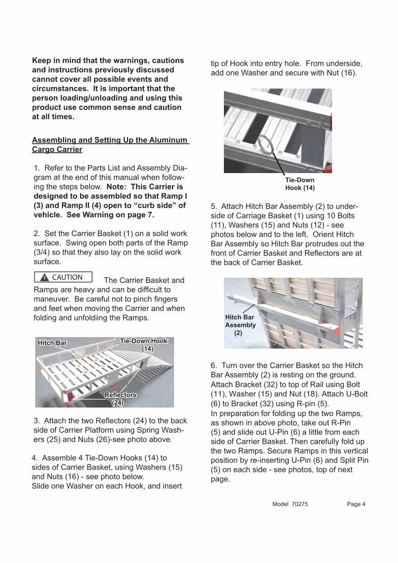
4. Assemble 4 Tie-Down Hooks (14) to
sides of Carrier Basket, using Washers (15)
and Nuts (16) - see photo below.
Slide one Washer on each Hook, and insert
tip of Hook into entry hole. From underside,
add one Washer and secure with Nut (16).
5. Attach Hitch Bar Assembly (2) to under-
side of Carriage Basket (1) using 10 Bolts
(11), Washers (15) and Nuts (12) - see
photos below and to the left. Orient Hitch
Bar Assembly so Hitch Bar protrudes out the
the back of Carrier Basket.
6. Turn over the Carrier Basket so the Hitch
Bar Assembly (2) is resting on the ground.
In preparation for folding up the two Ramps,
Attach Bracket (32) to top of Rail using Bolt
(11), Washer (15) and Nut (18). Attach U-Bolt
(6) to Bracket (32) using R-pin (5).
as shown in above photo, take out R-Pin
(5) and slide out U-Pin (6) a little from each
side of Carrier Basket. Then carefully fold up
the two Ramps. Secure Ramps in this vertical
position by re-inserting U-Pin (6) and Split Pin
(5) on each side - see photos, top of next
page.
CAUTION
Keep in mind that the warnings, cautions and instructions previously discussed cannot cover all possible events and circumstances. It is important that the person loading/unloading and using this product use common sense and cautionat all times.
(24)
Hitch Bar Assembly (2)
Tie-Down Hook (14)
Tie-DownHook (14)
Hitch Bar

WARNING
Model 70275 Page 5
7. The Aluminum Cargo Carrier is now
ready to be connected to the tow vehicle’s
hitch receiver. The Carrier is heavy and an
assistant should help with this task.
First remove the Safety Pin (10) and the
Hitch Pin (9) from the front of the Carrier’s
Hitch Bar.
Slide the Anti-Tilt Locking Bracket (31)
over the end of the Hitch Bar. The large
open end of the Anti-Tilt Locking Bracket will
face front and engage with vehicle’s hitch
receiver (see photo top right).
8. With assistance, lift the empty Carrier and
slide the open end of the Hitch Tube into the
vehicle’s 2” x 2” hitch receiver. Align the hole
openings on hitch receiver and Hitch Tube,
and put the Hitch Pin (9) in place. Secure
Hitch Pin with the Safety Pin (10).
R- Pin (5) and U-Pin (6)
U-Pin (6)
R-Pin (5)
Anti-Tilt Locking Bracket (31)
Vehicle’s Hitch Receiver
9. Slide the Anti-Tilt Locking Bracket (31) up
against the vehicle’s hitch receiver. Tighten
the two bolts on the underside of Anti-Tilt
Locking Bracket to tie together the hitch
receiver and the Hitch Bar (2) - see above
photo.
10. When ready to load the Aluminum Car-
go Carrier, take out R-Pin (5) and slide
out U-Pin (6) from each side of Carrier Bas-
ket. Carefully unfold Ramp I (3) and Ramp II
(4). Make sure the leading edge of Ramp II
rests solidly on the ground. Load the Car-
rier as needed. Use ropes and tie downs to
securely hold all cargo in place.
Do not exceed the 500 Lbs. maximum weight capacity. Weightinside the Carrier should be evenly dis-tributed.
11. When the Carrier is empty and not in
use, the two Ramp sections can be folded to
the vertical position (previously described in
paragraph #6 on pages 4 and 5), or the two
-
rier Basket - see photo on page 6.
Bolts (28)
HitchBar (2)

Limited Warranty
PGS LLC warrants to the original retail purchaser that the product is free of defects in material and workmanship at the time of shipment. This AluminumCargo Carrier is warranteed for 90 days from the date of purchase. This warranty is expressly in lieu of all other warranties, express or implied.Proof of purchase is required for warranty transac-tions; a copy of the original invoice or sales receipt is required.
Maximum WeightCapacity
500 Lbs.
Construction All AluminumFor Use With 2” x 2” Class II, III and IV
Hitch ReceiversCargo Bed Dimensions
47-3/4” x 27-3/4” x 7”
Hitch Pin 5/8” Diameter with R-Pin2 Included
SPECIFICATIONS
12 (continued)To place both Ramps inside the Carrier Bas-ket, carefully fold up the Ramps and lower them towards the bed of the Carrier Basket.
Use the strap attached to the Carrier Basket (1), to secure the Ramps inside the Carrier Basket (see photo below).
folding and unfolding the Ramps.
Maintaining the Aluminum Cargo Carrier
1. Frequently check the condition of the Carrier and the vehicle’s hitch receiver.Make sure all components are in good condition. If the Carrier or hitch receiver become damaged through accident, or if any weld damage is noted, the product should be replaced.
Check to make sure that all hardware is tightly secured in place. Frequently check the Anti-Tilt Locking Bracket (31) to make sure that the two bolts on the underside are tightened down to tie together the hitch re-ceiver and the Hitch Bar (2).
Folded Ramp I and Ramp II
Model 70275 Page 6
2. Keep the Carrier clean.
Strap

Model 70275 Page 7
Parts List
Assembly Drawing
1 Carrier Basket 12 Hitch Bar Assembly 13 Ramp I 14 Ramp II 1
2niP-R52niP-U6
7 Ring 48 Chain 2
20 Lock Nut 421 Bolt 222 Rubber Foot 223 End Cap 224 225 Spring Washer 426 Nut 427 Big Washer 628 Bolt 229 Nut 230 Washer
Anti-Tilt Bracket2113
32 U-Pin Bracket 233 End Cap 234 End Cap 2
Part # Description QtyPart # Description Qty
TRAFFIC SIDE
CURB SIDE
When assembling this Carrier make sure the Carrier Basket and Ramps are oriented as shown in the Assembly Draw-
rearward); for safety, Ramp must open towards “curb side” of vehicle. It can be hazardous to open the Ramp towards the
WARNING
Note: The Parts List and Assembly Diagram is provided as a reference tool only. Some parts are listed and shown for illustration purposes only, and are not available as replace-ment parts. All repairs to this tool (including replacing
-cian.
Manufactured and Distributed by: PGS LLC, 1270 Avenida Acaso STE E, Camarillo, CA 93012Tel: 805-987-1333 Fax: 805-603-1355
PGS LLC ensures complete satisfaction with this product. In the event of miss-ing or damaged parts please call toll free, Customer service hours 9:00-5:00, Monday-Friday, PST.,1-805-987-1333
Hitch Bar Assembly (2) is assembledunderneath Carrier Basket (1).
9 Hitch Pin 110 Safety Pin 111 Bolt 1412 Nut 1413 End Cap 114 Tie Down Hook 415 Washer 2616 Nut 417 Screw 38
18 Nut 3819 Bolt 2