7.4 civil and architecture -...
TRANSCRIPT
377
7.4 CIVIL AND ARCHITECTURE

378
CIVIL AND ARCHITECTURE GENERAL PROVISION FOR AIS SUB-STATION WITH OFFICE BUILDING
7.41 References 7.4.1.1 General The design and construction shall conform to the latest edition of the relevant codes andstandards. Any proposed substitution for the listed standards by an equivalent standard will besubjecttoapprovalbytheEngineer.Relevantstandardsinclude.7.4.1.2 Design and Construction Standards BS12 PortlandCement BSEN124 GullyandManholetopsforvehicularandpedestrianareas BS812 TestingAggregates BS882 Aggregatesfromnaturalsourcesforconcrete BS1377 MethodsoftestforsoilforcivilEngineeringpurposes BS1722:Part10 Anti-intruderfences BS1881 Testingconcrete BS2853 Designandtestingofoverheadrunwaybeams BS3148 Methodsoftestforwaterformakingconcrete BS3921 Claybricks BS4449 Steelbarsforthereinforcementofconcrete BS5262 Externalrenderings BS5395 Stairs,laddersandwalkways BS5572 Sanitarypipeworks BS5628 Codeofpracticeforuseofmasonry BS5930 Codeofpracticeforsiteinvestigations BS6031 Codeofpracticeforearthworks BS6367 Codeofpracticefordrainageofroofsandpavedareas BS6399:Part1 Codeofpracticefordeadandimposedloads BS6399:Part2 Codeofpracticeforwindloads BS6465 Sanitaryinstallations BS6651 Codeofpracticeforprotectionofstructuresagainst lightning BS6700 Design, installation, testing and maintenance of services
supplyingwaterfordomesticuse. BS8004 Codeofpracticeforfoundations BS8005 Sewerage BS8100 Latticetowersandmasts BS8102 Codepracticeofprotectionofstructuresagainstwatertheground
structuraluseofconcrete. BS8110 Structuraluseofconcrete BS820 Lightningofbuildings BS8215 Codepracticefordesignandinstallationofdamp-proofcoursesin
masonry BS8290 Suspendedceilings Bs8301 CodeofpracticeforBuildingdrainage

379
7.4.2 Design BothArchitecturalandStructuralDesignshallbesubmittedbythecontractortotheemployerforapproval.7.4.2.1 Architectural and structural Requirements of Buildings The details Architectural, Structural & other related drawing and design with Green Buildingconceptshallbesubmittedbythecontractortoemployerforapproval.
1. Structure : Modern Architectural designed R.C.C or Steel Framed Structure featured by
Green Building Technology.
2. Partition Wall : For all Exterior wall thickness should be 10 (ten) inches and interior wall
thickness should be 5 (five) inches and to be used 1st Class Bricks. All Brick wall should be plastered both sides as per standard (Except where
Fare-Facing Treatment to be used) In case of R.C.C. works 20mm down graded Stone chips should be used.
3. Covered Area : Minimum required area in Building are included with service areas & Other
Specific Functions - Control Room, Battery room, Cable Trench, Store, Office Rooms, Residential Accommodation, walkway, open Space & stair case etc.
4. Foundation : Considering 02 storied building (no Basement) (G+1)
(For AIS Regular type Sub-station) Plinth Level at +3ft above from Ground Level Ground Floor clear height 9’-6” ft Cable Trench & Ancillary Facility 1st Floor clear height 13’-6” ft for Control room
5. Floor/Roof Finish :
To be used 36 inch x 36inch size European standard Mirror Polished Homogeneous tiles for Ground & 1st Floor. Standard Quality Tiles for walk way or other common space.
6. Toilet/ Sanitary:
Floor and full height wall of the Toilet should be furnished by European Standard Tiles with decorative boarder.
To be used European Standard Commode, Basin and others Sanitary Fittings & Fixtures (such as Pillar Cock, Bib Cock, Push Shower etc.) should be European Standard as well as approved sample and design.
To be Constructed 50 users septic tank, inspection pit, sewerage line, apron, drain etc.
To be provided water supply system with Deep Tube well & over head water tank.
7. Electrical Fittings & Fixture :
Concealed Electrical wiring by Eastern/BRB/Paradise Fire Resistant Cable European Made MK type Gang switch, socket MCB etc Provision for Internet facilities system, Dish Line, Telephone
& Intercom wiring.

380
Sufficient Earthling facilities. To be used LED Light To be provided sufficient Air Conditioner To be provided sufficient Ceiling Fan
8. Interior Wall Finishing : Smooth Finished & soft colored Plastic paint should be used over the Plastering work of interior wall and ceiling.
9. Exterior Wall : Smooth Finished & Architectural approved colored weather coat should be used over the Plastering work of Exterior wall. Some where should be used Ceramic Facing brick / Rustic Tiles
10. Window : Window should be made Standard Quality Thai Aluminum frame and
minimum 5mm thickness glass. 11. Door : Door Frame and Shutter should be made by solid wood such as Burma
Teak, Teak Chambal, Chapalish etc. which shall be approved by the owner's engineer.
12. Stair Railing : Should be used approved designed SS Railing in the Stair case.
13. Sign, Signal & Annotation : ● Integrated Design of Different kind of Indicators like- Acrylic Sign Board, LED Sign Board, Neon Sign Board, Reception Sign Board, Safety Sign, PVC Letters, Glow
Sign Board, Customized Display Boards, Overhead
Signage, Metal Nameplates, Commercial Sign Boards,
Outdoor Signs, Electronic Sign Boards etc. should be
provided in the design & construction.
● Digital LED Signboard with the features of-
Excellent visibility (even in daylight); Good quality at reasonable
price and light weight; Simple installation, Safe to touch and
clean; Changing color for attracting attention; Extremely low
power consumption.
● Should be provided the Accessories like Adaptor and chains
etc.
14. Approval & Test : Over all Approval should be taken from concern office of the BPDB.
Materials & Item (if required) should be tested from any authorized
Institutions of Bangladesh furnished by the Contractor.
Thecolumnsofthegroundstoryshallbeextendedaboveroofleveltopermitstarterbarstobeleftinplaceforafuturestory.Anexternalconcreteopenstaircaseshallbeprovideduptotheroof.TheroofshallbeaRCCslabdesigned for5kN/m2liveloadforallfloorasperBNBC.Ifafuturestoryisnotrequired,afixedladderofgalvanizedsteelshallbeprovideduptotherooforprovidetemporaryCIsheetshadeoverthestaircaseasperdirectionoftheemployer.

381
The main entrance to all buildings shall be shaded, either by a projection of the roof over theentrance verandah or by a separate roof at a lower level. This area of roof shall also be limeterracedanddrainedbyrainwaterpipes.Theheadofeachdownpipeshallbefittedwithanenlargedhopperandpurposemadecast irongrillsetintorecessintheroofprojection.Windowopeningsshallbefittedwithprotrudingconcretesunshadesaboveandatthesidesoftheopenings.
All external walls shall be 250 mm first class brick work also provide 237.4mm x 68.75mm x12.5mm(9.5”x2.75”x0.5”)oranyotherstandardsizesofMirpurceramicsfacingbricksorsimilarapproved,orrenderedRusticTilesasrequiredbythearchitecturalplan.Theinternalwallsshallbegenerallyof125mmthickfirstclassbrickwork.InternalwallsshallallberenderedandreceiveonesealercoatplustwofinishingcoatsofPlasticemulsionpaint.AllbrickworkshallbetiedintotheRCCframebygalvanizedties.
Externally, rendered walls shall receive primer plus two finishing coats of PEP acrylic externalqualitypaintorsimilarapproved.
Theheightofcontrolroomsshallbeprovidedabout1(One)meterclearanceoverthetopofthecabinets to the underside of the false ceiling. In the switch gear rooms, about1meter clearanceshallbeprovidedovertheswitchgeartotheundersideroofslabbuttheContractorshallprovideagreaterclearanceifitisrequiredtoremoveequipment.Theclearancemaybereducedbelowdownstandbeamsprovidednoequipmentisrequiredtoberemovedfromthetopoftheswitchgear.Allroomsinanybuildingshallbeoneheight.
Control buildings housing switch gear and control equipment shall include a cable basement tofacilitates connection to the equipment. Basements shall be constructed so as to protect thebuildingsubstructurefromwaterinaccordancewithBS8102.
7.4.2.2 Ground conditions, Foundations and Site Investigation
(a)FillSitesOnfillsiteswherethedepthoffillexceeds3metersthecontractassumespiledfoundationsshallbe installed below buildings. If placed foundations are found to be unnecessary in the final siteinvestigationreport,areductionincontractvalueshallbeagreedonthebasisofschedulerates.Pilesshallbeconcrete(cast insituorpre-cast)complyingwithBS8004.Wheretimberpilesareused,adequatestripfootingsshallbeprovidedtosupportthebuildingafterthetimberpileshavedeterioratedbywhichtimesettlementwillbecomplete.
On every fill site the Contractor shall prove that his switchyard foundation will not suffersettlement greater than 20 mm by constructing a foundation and load testing this to twice thedesignbearingpressureforaminimumof20days.
Outdoorequipmentshallbeprovidedwithspreadfootings.TheContractorwillbeprovidedbytheEmployerwithasurveyofsoillevelspriortofilling.TheContractorshallimposethesitelayoutonthesurveytocheckforunevendepthoffillbelowanyfoundationandwhereunevendepthoffillexistshisfoundationproposalsshallrestrictfinaldifferentialsettlementtoa1in400slopes.
Ifafillsitehasnotbeenexposedtoonewetseasonbeforefoundationworkstarts,theContractorshall flood the site to a depth of 50 mm for 10 days (Not required on hydraulic fill site). Thisrequirement is because silty sands will generally compact to a denser condition on first timeflooding.

382
On all fill sites the Contractor shall pipe rainwater from pipes down to paddy level and shallpreventwaterpondinopenfoundationsandbackfillallfoundationsassoonaspossible.
TheContractorshallmonitorsettlementofthefill(byplacingconcreteposts50x50x750mmdeepona10metergridandtakingreadings)at30dayintervalsfromthetimeheisgivenaccesstoeachfillsite.
When a fill site is handed over to the Contractor, The Contractor shall become responsible formaintainingtheentirelyofthefillingoodcondition,includingallbatterslopes.(b)UnfilledSites
Originaldeltalevelsaregenerally4metersbelowroadlevel.Thereforemostsitesarehistoricallyfillsitesbutfillsettlementcansensiblybeconsideredcomplete,wherefillisover3yearsold.
(c) Site Investigation TheContractormayappointasubcontractortocarryoutthesiteinvestigationsbutallworkandalllabworkshallbewitnessedbyoneofhisownstaffwhoshallcountersignallrecordeddata.The site investigations and analysis of the data in a final report giving full details of foundationproposalsshallbecompletedateachsitebytheprogrammeddate.Boreholesshallbetakenona25metergridwithat leastthreeadditionalboreholesbesideeachbuilding.Additionalboreholesmayalsoberequiredwhereunevenfilldepthisencountered.Theboreholesshallbelocatedtoanaccuracyof±0.5mandshallbelocatedtositelayout.Boreholesshall be a minimumof20 meters depth or twice building footing width, whichever isgreateroraspersitecondition&decisionoftheemployer.Allboreholesshallbebackfilledwithcompactedsand.Ineachboreholethefollowingtestsshallbecarriedout:Standardpenetrationtestsat1.5meterintervals.Undisturbedsamplesshallbetakenataround1.5metersdepthand3metersdepthandtestedbyunconfinedcompressiontests.Onedimensionalconsolidationtestsshallbecarriedoutonundisturbedsamplestakenat1,5,3and4.5 meters depth. The samples shall be saturated and the range of applied pressure shall fullyreflected the in situ conditions. Graphs showing void ratio(e) and applied pressure shall besubmitted along with the coefficient of compressibility for the range of loading anticipated. Mvshallbeinm2/MNandshallberecordedateachstressincrement.Thecoefficientofconsolidation,cv,shallbegiveninm2/year.Particlesizeanalysisshallbecarriedoutforeachstratumandspecifiedgravity,moisturecontent,liquidlimitandplasticlimitdetermined.Groundwaterlevelshallbedeterminedbydippingtheboreholes.Wherecollapseoftheboreholesoccurs,casingshallbeusedandleftinuntilthewaterlevelremainsconstantfortwodays.IncohesivesoilsavanetesttoBS1377:part9shallbecarriedoutatthreedifferentdepths.TheContractorshallchecktheaggressivelyofsoilandgroundwaterateachsitetoconcreteandtakeallmeasuresnecessarytoensurethelongtermdurabilityofconcrete.(d)SiteInvestigationReport

383
The reportshall be submittedby the key dateat each site given in the program. TheContractorshall submit 2 copies of the report to the Engineer. The report shall propose full details offoundationsandloadingthereonandshallprovideestimatesoflikelysettlementsanddifferentialsettlements.ThereportshallbetheworkoftheContractor’sownfoundationEngineers.IftheContractorusesalocalsiteinvestigationcontractor,heshallappointoneofhisownstafftooverseetheentireoperationandeachpieceofdatashallbecountersignedbythisperson. TheContractorshallsupply,installandtestatleastoneofthetypesofPileinaccordancewiththeapproveddesignandthedrawingshowingthePilingarrangement.EachPileshallbesuiteexistingthesub-strataatthesite. (e)Foundations
Theminimumdepthofallfoundationsshallbe: (i) Transformerbasesbound 0.9m (ii) Allotherswitchyardfoundations 1.1m (iii) Controlbuildingfoundations, 1.5m includingallwallfoundations andinternalwallfoundations
(iv) Boundarywallfoundations 1.1mAllformationsshallbehandrammedormechanicallycompactedbeforeplacing70mmminimumthickness of Class B concrete blinding, within 24 hours of bottoming excavation, which blindingshallproject300mmminimumdistancebeyondallfootings.EachfootingshallbeinspectedbytheEngineer.Wheresoilconditionispoor(onfillsitesoralreadyfilledsites)orwheretheContractorleavesfoundationsexposedandsoilconditionsdeteriorate,oneofthefollowingmeasuresshallbecarriedoutasagreedwiththeengineer. (i) Blindingdepthandprojectionshallbeincreased (ii)Softsoilshallberemovedandreplacedwithcompactedvitisandwiththetop200
mmconsistingofvitisandandbrickchips.ThecostofthisworkshallbebornebytheContractor.Betweencolumnfootingsallwalls, includingallinternalwallshallbeprovidedwithareinforcedconcretestripfootingofminimumdimension800mmwideby250mmdeepplacedatthesamelevelascolumnfootingsandlinkedstructurallytothefootings.Inadditioncolumnfootingsshallbetiedatfoundationlevelandalsofloorlevelbybeamstoeveryadjacentcolumninbothorthogonaldirections.Thesebeamshallbedesignedtoresist1in200differentialsettlementwithoutdistressandshallbecapableofresistingtheearthquakeloadofChittagongregionasperBNBC2012Thedeepestpartsofanyfoundationsshallbecompletedfirst.Allfoundationsshallbecompletedandbackfilled,includingallcabletunnelandcabletrenchworkinsidebuildings,beforewallsareraised above floor levels. All other foundations shall be back filled within 7 days of completingconcerning.Allexposedconcreteandoutersurfacesofcabletrenchesandcabletunnelsshallreceivetwocoatsof bitumastic paint before back filling to reduce ingress of water. The Concrete surface shall begroundsmoothandallairholesetc.filled(rubbeddownwithacementslurry)beforepainting.TheContractorshallmonitorsettlementofallfoundationseachmonthandreportthissettlementtotheEngineeruntilsettlementhasreducedtolessthan1.5mmin3months.

384
Thetopsofallfoundationsshallterminate1000mmabovesiteaveragefinishedsurfacelevel.Allexposededgesshallhave20mmx20mmchamfers.Excavation shall only be carried out when the ground water table at least 1000mm belowfoundation level. The excavation shall be kept dry during the construction period by providingsumps and pumps as required. During the rain season, shelters shall be erected over all openexcavations.AnyoverexcavationshallbefilledwithClassBconcrete.Allbackfillshallbecompletedto95%maximumdrydensityasdefinedbyBS1377testmethod.2.5Kgrammer.Before starting foundation work the Contractor shall clear all sites of trees, tree roots shrubs,debris,surplussoil,andanybuildings.Foundationsshallbedesignedtoresistuplift,assumingthewatertableisatgroundlevelandtheweightofsoilrestingonafoundationisthatincludedwithina150frustum.Onfillsiteswherethedepthoffillexceeds3meters,theContractorshallprovidepiledfoundationsinaccordancewithBS8004forcontrolbuildings.Iftimberpilesareused,adequatestripfootingsshallbeprovidedtosupportthestructureafterthetimberpilehasdeteriorated,bywhichtimethefillwillbefullyconsolidated.OneworkingpilechosenbytheEngineershallbeloadtestedateachsiteto150%ofdesignloadinaccordancewithBS8004. 7.4.2.3 Drainage The entire surface within boundary walls shall be of uniform sloping site, sloping at q in 150minimumslopetoopenchannelsaroundtheentireperimeter.Thesechannelsshallbedesignedfor a rainfall intensity of 60 mm per hour. Out side the boundary wall the contractor shall beresponsible for drainage up to 20 meters from the wall and willat some sitesneed to constructoutletswithsuitableerosionprotectiondowntopaddylevel.Theconcretewallofcabletrenchesshallprojectatleast70mmabovebrickpavingleveltopreventrunoffenteringthecabletrench.Thefloorsofallcabletrenches/tunnelsshallbeslopedtosoakways.The cable trenches shall be free from surfacewater drainage. If the cutoffarea exceeds 30 m2 itshall be drained by a 200 mm minimum diameter concrete pipe to the boundary drain. TheContractor’s drainage design shall avoid all pond water to avoid forming a mosquito breedingground.Alldrainagepipeworkwithinbuildingsshallbeductileiron,generallyof100mmdiameter.Floordrainsshallbeplacedineachbatteryroomandtoilet.External Pipe work shall be 150 mm minimum diameter concrete pipes at a minimum depth ofinvert of 700 mm. Where pipes, including existing pipes along with site, are less than 400 mmaboveadjacentfoundationstheyshallbesurroundedinconcrete.Whererequired,drainagepipesshallbekeptbelowcables,allowing1.1mcovertotopofpipes.

385
Manholesshallbeofbrickconstructionwith600mmx600mmclearopeningsandairtightductileironcoverstoBSEN124.Manholesshallbelocatedateachchangeofdirection.Minimumfallonallpipelinesshallbe1in80.Manholeshallnotbelocatedinroads.The Contractor shall be responsible for all negotiations with local authority WASA where aconnection to a public sewer is proposed. Where high water levels in public sewers may causeeffluent to back up into a site, non return valves shall be fitted. The Contractor shall provide allprotection required to existing sewers and shall deepen foundations, including boundary wallfoundations,whererequiredallfoundationsarebelowadjacentsewers.TheContractorshalldrawlongitudinalsectionsofallpipelines.Eachcontrolbuildingshallbeprovidedwithaseptictankdesignedfor10usersandasoakawayofopen brick construction 11 m deep by 2.2m diameter filledwithbroken bricks. The septic tankshallbelocatedatleast15metersfrombuildings.Otherbuildingsshallhaveseptictanksdesignedfortherequirednumberofusers.Allfouldrainsshallventedbyaventpipitoaboverooflevel.Theinnersurfaceofallmanholesandseptictanksshallbepaintedwith2coatsofbitumasticpainttoprotect it against sulphate attack. The septic tank shall have access holes directly over the inletpipes and outlet pipes. Where public sewers exist alongside a site, the Contractor shall connectdirectlytothefoulsewer,providedeffluentfromtheseweristreated.TheContractorshallconstructthedrainagefirsttoensurethatatnostageisrainwaterpondedonanypartofthesite.Allrainwatershallbeabletorunoffthesiteorshallbeimmediatelypumpedoff site by the Contractor. The Contractor shall complete all necessary drains before casting anyroof and large concrete area which will create large run off. The condensate drains for the airconditioningshallalsobeconnectedtothedrainage.Twoventsofminimumheight2.2mshallbeprovidedoneachseptictank.
Ifatown’swatersupplyisunreliable,theroofrainwatershallbecollectedinanundergroundtankofstandardEmployer’sdesign.ScopeofthisworkshallbeagreedatBidstage.7.4.3 Earth Work 7.4.3.1 Scope Thisclausecoverstheperformanceofallworksinconnectionwiththerequiredexcavationforthevarioustypeoffoundationsandequipment,asshowninthedrawing,oranyotherexcavationandbankingthatmaybenecessaryduringtheprogressofworksincludingtheremoval,useordisposalofallexcavatedmaterials.
7.4.3.2 Clearing
(1)Clearingshallmeanincludetheremoveoftreesandshrubs,stumpsandotherobjectionablemattersfromtheareanecessaryfortheworks.ThecontractorshallcutandremovethemfromtheprojectareaorturnthemasapprovedbytheEngineer.
(2) Bynomeansshallthecontractorfellanytreesoutsidethepremiseoftheconstructionsitewithout permission of the parties concerned even if such trees cause obstacle againstsmooth execution of the work. Therefore, any such trees shall be felled upon negotiationwithandpermissionofthepossessor.
7.4.3.3 Excavation
(1) Excavation under this section shall consist of the removal, hauling, dumping andsatisfactorydisposalofallmaterialsfromrequiredexcavations.

386
(2) The excavated slope surface shall be protected against any erosion due to heavy rainsduring construction period. Should any damage be caused on any face of slope, thecontractorshallimmediatelyrepairanysuchdamageathisexpense.
(3) Excavationshallbecarriedoutbyadoptingasuitableexcavationforthegroundsoasnottoloosen the ground outside the excavation. If necessary, temporary sheeting shall beconstructed.
(4) During excavation, work shall be performed carefully so as not to cause any damage toadjacentstructuresandburiedstructures.
(5) If the excavated material is to be temporarily stockpiled, designated spaces shall be keptfromtheshoulderoftheroadwhileconsideringtheearthpressureattheexcavatedsurfaceandtheworkingspace.Temporarysheetingorothersuchstructures,ifnecessary,shallbeconstructedsothatthestockpilecanbeprotectedfromdamageorbeingwashedaway.
(6) Excavationofroad,ifany,shallbedoneinsuchamannerasnottohampervehiculartraffic.Ifexcavationistobeperformedinthevicinityofresidences,appropriatecareshallbetakensoasnottohinderthepassageofresidents.
Spoils,materialsandequipmentshallbecarefullyhandled.(7) Aftercompletionofexcavation,excavatedwidthsandbottomsshallbesubjecttoinspection
bytheengineer.
(8) Blastingshallnotbeemployedduringexcavation.
(9) Any and all excess excavation for the convenience of the contractor or over-excavationperformedbythecontractorforanypurposeorreason,exceptmaybeorderedinwritingby the engineer, and whether or not due to the fault of the contractor, shall be at theexpenseofthecontractor.Allsuchexcessexcavationandotherexcavationshallbefiledattheexpensebythecontractorwithmaterialsapprovedbytheengineer.
(10) Thecontractorshallbeentitledtorequesttheengineerinwritingtochangetheexcavationlineasrequiredaccordingtothesoilconditionsofthefoundationfollowingtheprogressofexcavation. In such a case, upon excavation up to the laid excavation line, the contractorshall prepare the detailed design drawing of the said foundation and submit it to theengineerforhisapproval.
(11) All objectionable materials such as, oil, mud, rock fragments, loose rock, chips, mortar,organicmattersandstagnantwater,shallberemovedfromthesurfaceofthefoundation.
7.4.3.4 Sheeting
(1) Sheeting shall be of the type that is suitable to the condition of foundation and Groundwaterandshallhaveasafestructure.
(2) If sheet piles on retaining piles are to be driven at the piling location in the vicinity ofburied structures, where they shall be investigated and confirmed by manual trenchexcavation etc. prior to piling in order to protect these structures from being damagedwhenpilesaretobepulledout,carefulnessshallbetakenintoaccounttocausenodamagetotheburiedstructures.
7.4.3.5 Banking
Foundationofbankingshallbetreatedasfollows:
(1) Anymaterialhavingaharmfuleffectonbankingshallberemoved.(a)Where inflow of ground water is expected, it shall be treated so as not to cause
inundation.

387
(b)In case of sloped ground with unfavorable conditions, such as unsuitable soil, poordrainage,etc,amethod,suchasexcavatingthegroundintostepsinadvanceinordertoincreaseitsstability,shallbeplannedandreportedtotheEngineer.
(2) Unless otherwise specified, settlement allowance shall be 3 per cent of the height of the
bankingandthesurfaceshallbegradedevenlywithin=5cm.(3) Materialsforbankingshallnotincludeanyharmfulmaterials,suchasfertilesoilorpieces
sowood.(4) Materialsforbankingshallnotbeofanextremelyswellingnature.(5) Impermeable clay shall not be used for back-filling of a structure which is susceptible to
earthpressure.(6) Bankingshallbeformedbyspreadingsoiloflessthan50cminthicknessandbysufficiently
compactingeachlayer.(7) Thetypeofcompactorshallbeonethatissuitableorbandingmaterials.(8) Materials forbankingshallbeso treatedastohaveoptimumwatercontent inpercentof
dryweight.(9) Rocksshallbespreadoutevenlysoasnottoformanyvoidspace.(10) Temporaryfacilitiesshallnotbeburiedinbanking.Ifitbecomesinevitabletodoso,itshall
bereportedtotheengineerandshallbeapprovedbytheengineer,uponwhichappropriatemeasuresshallbetakentopreventanyunfavorableeffectonthebanking.
(11) Asastandard,extentofsatisfactorycompactionshallbeasfollows: K75=1.5Kg./cm3ormore Where:K75isacoefficientofbearingcapacitydeterminedbytheplateloadtest. When required by the engineer, the contractor shall perform in-sity tests and
penetration test to confirm the extent of compaction and the result shall be submitted totheengineer.
(12) AnybankingworkonrainydayshallbecarriedtouponapprovaloftheEngineer.7.4.3.6 Back-Filling(1) Back fillingshallbeexecutedasconstructionproceedsalongwiththeremovalofshoring
andothermaterialsatthebackfillingsite. Whensheetingistobeleftandburiedinordertopreventshearfailureofsoilordue
to some other inevitable reasons, it shall be done so according to the direction of theengineer.
(2) Exceptthosewhicharespecifiedinthespecificationsorthedrawings,allthematerialsfor
backfillingshallbeinaccordancewiththeclausesof“Banking”2.5ofthesespecifications.(3) Iftheinflowofwaterexistsatthesiteofbackfillingitshallbeappropriatelytreated.

388
(4) Inbackfilling, thelayerofspreadingshallbearound50cmor lessper lift,anditshallbegradedashorizontallyaspossible,andshallbesufficientlycompactedbyhydraulic fillingorbyuseofanappropriatecompactorsuchasarammer.
(5) Extentofcompactionshallbesuchthatitwillpreventfuturesettlementandsuchthatthedesignatedbearingcapacitycanbeobtained.Ifnecessary,theextentofcompactionshallbemeasuredbyaconepenitrometeretc.andtherecordshallbesubmittedtotheengineer.
(6) Ifthereisanysurfaceorburiedstructureownedbythepublicorthethirdpartyatthesite
of back filling, care shall be taken so as to cause no harmful effect to them, and theexecution of the workshallbe carriedout following direction by the engineer and in thepresenceofrelevantadministrators.
(7) Forbackfillingadjacenttoastructure,compactionandbackfillingshallbecarriedoutin
suchamannerthatwillpreventdamagetothestructure. Nostonesorthelikeshallbeusedforbackfilling.7.4.3.7 Disposal of Excavated Materials(1) Spoilsproducedbyexcavationshallbepiled,graded,slopedordisposedofatthelocations
specifiedbytheBoardorEngineeranditshallbesubjecttoinspectionbytheengineer.
Spoil,whosedisposalareasarenotspecifiedbytheengineer,shallbedisposedofbythecontractorathisresponsibility.
(2) In transporting the spoils, care shall be taken so as to neither hamper traffic nor cause
troubletothethirdpartybyscatteringthespoilovertheroad.7.4.3.8 Gravel Layer
(1) Gravelandrubbleproducedlocallyshallbeused.Gravellayershall,inprinciple,belaidinasingle layer with no large gaps, stand on end and interstices shall be filled with granulargravel.
(2) Thecompactionshallbeexecutedbyacompactionmachine(rammers,etc.)(3) Gravellayershallbewellcompactedtogetherwithcoveringgravelandshallbegradedand
finishedtothedesignatedlevel.7.4.4 Piling 7.4.4.1 Pile Driving(1) Pilesshallbedrivenbyapiledriver,suitableforthetypeandsizeofthepiles,geological
conditions and construction environment, and in such a manner as to cause no publicnuisance,suchasnoise,tothethirdparty.
(2) Themethodforconstructionjointofpilesshallbesubmittedinwritingtotheengineerand
shallbesubjectforapprovalbytheengineer.(3) Records shall be kept during the poling operation and these shall be submitted to the
engineer.

389
(4) Pilesshallbedrivenverticallyandattheexactlocationsindicatedinthedrawings,andpiledrivingshallbecontinuouswithoutinterruptiontoavoiddeviationofpilehead.
(5) Capsandothersuitablematerialsshallbeusedasacushiontoprotecttheheadofpiles.(6) Toward the end ofdriving the amount ofpenetration shall be measured for each pole as
directedbytheengineer.(7) Shoulditbedifficulttodriveanypileuptothespecifieddepth,thecontractorshallcarry
outsuchpillingworkinaccordancewiththeinstructionsoftheengineer.(8) Method and equipment of pile driving to be employed for construction works shall be
subjecttoapprovaloftheengineerpriortoexecution.(9) When driving a group of piles, driving shall begin from the center and gradually moved
outward.(10) Wheneccentricerrorexceedstheallowablevaluesshowninthetablebeloworwhenapile
isdamagedorcreakedduringpilingoperation,itshallbereportedtotheengineer,andthepileshallbereplacedoranadditionalpileshallbedriven.TypeofFoundation Allowance RemarksAllfoundations 10cmorless
(11) Upon completion of piling, any void portions inside piles shall be filled back with soil
obtainedfromatsiteexcavation.7.4.4.2 Field Joining of Piles(1) Fieldjoiningofpilesshallbecarriedoutbyarcwelding.(2) Welders shall have not less than 6 months continuous experience in welding of pile, and
shallbequalifiedbyJISZ-3801,“StandardQualificationProceduresforweldingTechnique”,orequivalentBDS.
(3) AreweldingrodsshallbestandarditemsspecifiedinIETC(InternationalElectrotechnical
Commission)orequivalent“CoveredElectrodesforMildSteel”,orequivalent. Weldingrodsshallbecompletelydrypriortouse.(4) Theweldingsurfaceofparentmetalshallbecarefullycleanedofslag,moisture,dust,rust,
oil,paintorotherforeignmatter.(5) Therootfaceofsteelpipepileshallbe2mm,(6) Welding shall be performed carefully by selecting welding current and welding speed
whichensurecompletepenetrationofweldingroodtoavoidcracks in anyportionof theweld.
(7) Weldingshallnotbeperformedwhentheparentmetaliswetfromrainfallorwhenstrong
windsareblowing.However,whentheportiontobeweldedinsuitableprotected,weldingmaybeperformeduponapprovaloftheengineer.

390
(8) If harmful defects or cracks have been found in the weld, the deposited metal shall becarefully chipped off and the affected part shall be re-welded and then inspected by theengineer.
7.4.4.3 Treatment of Pile head(1) The head of the pilesshall be cut to the designated level and shall be embedded into the
footing.(2) Thesteelpipepilesshallbeanchoredintothefootingbyamethodspecifiedotherwise. 7.4.4.4 Transportation and Handling Careshallbetakenintransportationadhandlingofpolesoastopreventdamagetothem.If the pile is damaged or deformed to the extent that it is impractical for the intended use, thecontractorshallrepairitpriortodriving,anditshallbeinspectedandapprovedbytheengineer.7.4.5 Reinforced Concrete Work 7.4.5.1 General(1) This clause covers the performance of all reinforced of all reinforced concrete work for
permanentstructuresinaccordancewiththedrawingsandthesespecifications.(2) Thecontractorshall furnishallmaterialsandequipment for theperformanceofconcrete
work.(3) Reinforced concrete work and plain concrete work shall comply with ACI (American
ConcreteInstitute),BNBC(BangladeshNationalBuildingCode)orequivalentstandard.(4) Covering (a)Thecoveringshallbeatleastonediameterofthereinforcement. (b)Ingeneral,thecoveringshallbeatleastthoseshowninTable-1.
Table-1 : Minimum Covering (mm)
Conditions Slabs Beams Columns Whennotdirectlyexposedtorainorwind 20 40 40 Largeandimportantstructure,orwhenexposedtoRainorwind
25 40 65
When effective coating is not applied on theportion Which may be subjected to injuriouschemicalreaction
Duetosmoke,acid,oil,salts,etc. 37.4 50 75
(c) Incaseoffootingsandimportantmembersofastructureitisrecommendedthatthecoveringbeatlest7.4cmwhenconcreteisplaceddirectlyfacingtheground,andatleast 5 cm for bars with diameter of more than 16cm and 4 cm for bars with thediameter of less than 16 mm when the concrete is buried and directly facing thegroundorwhenitissubjectedtosevereweatherconditions.However,thecoveringat

391
thebottomsideofslabsmaybeatleast2.5cmeveniftheportionofitissubjectedtoextremeweathercondition.
(d) The covering in structures which are required to be especially fire-proof shall bedetermined based on the temperature of the fire, duration, characteristics ofaggregatetobeused,etc.
7.4.5.2 Quality of Concrete
(1) GeneralConcrete shall have the uniform quality with the required strength, durability, water
tightnessetc.
(2) Strength
(a) Thestrengthofconcreteshallgenerallybebasedon28dayscompressivestrength.
(b) CompressiontestsforconcreteshallbeperformedinaccordancewithACI,BNBCorequivalentstandard.
7.4.5.3 Materials
Materials used for the construction of buildings shall conform to standard specifications
listed in this part of the Code. Any deviation from the type design or architectural detail
fromthosespecifiedinthesestandardsmaybeacceptedbytheBuildingOfficialaslongas
thematerialsstandardsspecifiedthereinareconformedwith.
7.4.5.3.1 CementCementforshallbeOrdinaryPortlandCementcomplieswiththestandardslistedasfollows:
BDS232:1974,PortlandCement(OrdinaryandRapidHardening)orASTMC150,Portland
Cement;ASTMC91,MasonryCement;ASTMC595,BlendedHydraulicCements.
Cement for other than masonry shall conform to the following standards: BDS 232,
Portland Cement (Ordinary and Rapid Hardening); BDS 612, Sulphate Resisting Portland
Cement-Type A;ASTMC150, Portland Cement; ASTMC 595,BlendedHydraulic Cements;
andtoothersuchcementslistedinACI318.
7.4.5.3.2 Water
(1) Watershallbefreefrominjuriousamountsofoils,acids,salts,organicmaterialsorothermaterialsthatmaybedeterioustoconcrete.
(2) Seawatershallnotbeusedinmixingconcreteforreinforcedconcrete.
7.4.5.3.3 Fine Aggregate
(1) General Fine aggregate shallbeclean, strong, hard, durable, suitably graded and free from
injuriousamountsofdust,mud,organicimpurities,saltsetc. Beachsandshallnotusedforconcrete.
(2) Grading
Fine aggregate shall consist of large and small particles suitably mixed, and itsgradingshall,asastandard,bewithintherangeshownintable2.

392
Table-2 : Standard Grading of Fine Aggregate
NominalSizeofSieve(mm)
Weightpercentageofthosepassingasieve
Nominalsizeofsieve(mm)
Weightpercentageofthosepassionasieve
10 100 0.6 25–65 5 90–100 0.3 10–35
2.5 80–100 0.15 2–10 1.2 50–90
SieveanalysisshallbeinaccordancewithJISA1102,orequivalentBDstandard.
7.4.5.4 Coarse Aggregate
(1) General Coarseaggregateshallclear,strong,hard,durable,suitablygradedandfreefrominjurious
amountofflakes,elongatedpieces,organicimpurities,saltsetc.(2) Grading Coarseaggregateshallconsistof largeandsmallparticlessuitablymixed,and itsgrading
shallbewithintherangeshowninTable3asastandard. SieveanalysisshallbeperformedinaccordancewithJISA1102,orequivalentBDstandard.
Table-3 : Standard Grading of Coarse Aggregate
SS(mm) Weightpercentageofthosepassingasieve
SA(mm) 50 40 30 25 20 15 10 5 2.5
95 40 10 0
40 100
100 65 30 5
95 30 0 0 25 100
100 70 10 5
SS :NominalSizeofSieve SA :SizeofAggregate 7.4.5.5 Reinforcement
Reinforcement in masonry shall conform to the standards listed as follows: ASTM A82,
Cold Drawn Steel Wire for Concrete Reinforcement; ASTM A615M, Deformed and Plain
Billet Steel Bars; ASTM A616M, Rail-Steel Deformed and Plain Bars; ASTM A617M, Axle-
Steel Deformed and Plain Bars; ASTM A706M, Low-Alloy Steel Deformed Bars; ASTM
A767M, Zinc-Coated (Galvanized) Steel Bars; and ASTM A775M, Epoxy - Coated
ReinforcingSteelBars.
7.4.5.6 Crushed Stones CrushedStonetobeusedascoarseaggregateshallconformtothefollowingstandards:

393
BDS243:1963,CoarseandFineAggregatesfromNaturalSourcesforConcrete;ASTMC33,
Concrete Aggregates; ASTM C330, Lightweight Aggregates for Structural Concrete; ASTM
C637,AggregatesforRadiation-ShieldingConcrete;ASTMC332,LightweightAggregatefor
InsulatingConcrete;IS:9142ArtificialLightweightAggregatesforConcreteMasonryUnits.
7.4.5.7 Admixture
AdmixturestobeusedinconcreteshallbesubjecttopriorapprovalbytheBuildingOfficial
andshallcomplywithSec.2.4.5.1through2.4.5.5.
Chloride : Calcium chloride or admixtures containing chloride from admixture
ingredients shall not be used in prestressed concrete, concrete containing
embeddedaluminuminconcretecastagainstpermanentgalvanizedmetalforms,or
inconcreteexposedtosevereorveryseveresulphate-containingsolutions(seeSec
5.5.2.1ofPart6).
Standards : Air-entraining admixtures shall conform to ASTM C260. Water-
reducing admixtures, retarding admixtures, accelerating admixtures, water-
reducing and retarding admixtures, and water-reducing and accelerating
admixtures shall conform to ASTM C494, Chemical Admixtures for Concrete, or
ASTMC1017,ChemicalAdmixturesforUseinProducingFlowingConcrete.
Pozzolanas : Flyash(PulverizedFuelAsh)orotherpozzolansusedasadmixtures
shallconformtoASTMC618.
Blast Furnace Slag : Ground granulated blast-furnace slag used as an admixture
shallconformtoASTMC989.
Pigment for Coloured Concrete : Pigment for integrally coloured concrete shall
conformtoASTMC979.
7.4.6 Storage of Materials
7.4.6.1 Storage of Cement
(1) Cementshallbestoredseparatelyforeachtypeineithersilosordamp-proofwarehouses.(2) Silostostorecementshallbebuiltorequippedwithsuitablemeanssothatcementwillnot
beretainedatthebottomwithoutbeingconveyedout. Incaseofsackedcement,itshallbestackedonthefloorrisingatleast30cmfrom
thesurfaceortheground,andshallbestoredinsuchamannerastofacilitateconveyanceandinspection.Heightofeachstackshallbeatmost13sacks.
(3) Any portion of Cement which has hardened during its storage shall not be used at all.Cementstoredforlongperiodshallbetestedforitsqualitypriortoitsuse.
(4) Cement with excessively high temperature shall be used only after lowering the
temperature.
7.4.6.2 Storage of Aggregate
(1) Fineaggregate,coarseaggregateandotheraggregateofdifferenttypeandgradingshallbeseparatelystoredbetweeneach.
(2) When receiving, storing and handling aggregate, facilities shall be well maintained, and
handlingshallbecarefullyperformedsothatnosegregationof largeparticles fromsmall

394
onesmayoccur,noforeignmaterialsmaybecomemixed,orincaseofcoarseaggregate,noparticlesmaybecrushed.
(3) Storage facility of aggregate shall be equippedwith a suitable drainage system, and shallhaveasuitablecapacitysothattheaggregatewithuniformsurfacewatermaybeusedandtheaggregatereceivedmaybeusedafterbeingtested.
(4) Inhotweather,aggregateshallbestoredinaplacewithafacilitytoavoiddirectexposuretothesunetc.sothatextremedryingortemperatureriseintheaggregatedoesnotoccur.
7.4.6.3 Storage of Reinforcement
Reinforcementshallnotbedirectlyplacedontheground,anditshallbestoredinawarehouseoraplacewithsuitablecover.7.4.6.4 Storage of Admixture(1) Admixtureshallbestoredsoas tobe free fromdustsandother impurities.Admixture in
powerformshallbestoredinsuchamannerthatabsorptionofwaterandhardeningareprevented,andadmixtureinliquidformshallbestoredinsuchamannerthatsegregationandchangeinqualityareprevented.
(2) Admixturematerialsshallbecarefullyhandledsoasnottobescattered.(3) Admixturematerialshallbestoredinsilosorwarehouseswhicharedesirablydamp-proof
andshallbeusedinthesameorderastheyarereceived.(4) Admixturestoredforalongperiodoffoundtohavechangedshallbetestedpriortoitsuse.
Should it be found in the test that the admixture does not possess the requiredcharacteristics,itsuseshallnotbeallowed.
7.4.7 Testing of Materials(1) The all materials (cement, water, fine aggregate, coarse aggregate, reinforcement,
admixture,etc.)tobeusedshallbeapprovedbytheengineerafterthecontractorsubmitstheresultsoftests.
(2) ThetestingmethodshallcomplywiththevariouscodesofASTM,ACI,BNBCorequivalent
standard.7.4.8 Mix Proportions 7.4.8.1 General (1) Mixproportionforconcreteshallbedeterminedinsuchamannerthattheunitquantityof
water is minimized while the required strength, durability, water tightness and theworkabilitysuitablefortheworkaresecured.
(2) Mixproportionforconcreteandresultsoftestmixingshallbedeterminedsoastoprovidetherequiredstrength,workability,uniformityanddurability.Theschemeofmixproportionshallbesubmittedtotheengineerforapproval,Theattachedformofsubmissionshallbeused.Thedesignstrengthsoftheconcreteshallbetheclassesindicatedbelow.
4Fc = 210kg/cm2 ForArchitectureandSwitchyard 4Fc = 180kg/cm2 ForTransmission 4Fc = 120kg/cm2 ForlevelingConcrete

395
Where4Fcmeansconcretecompressivestrengthattheageof28days. Basicdesigndateformixingareindicatedinthetableherein.
Table – 4 : Basic Mix Data
Class Designstrength4Fc(kg/cm2)
Maximumsizeof
aggregate(mm)
Slump(cm)
Airentertainment
(%)
E 210 25 10–15 41 ArchitectureSwitchyard
B 180 40 10–15 41 Transmission C 120 40 10–15 41 LevelingConcrete
Note :1. Specificgravityindesign Cement–3.15,FineAggregate–2.62,COARSEAggregateandCrushedStones–2.622. RelationshipbetweenC/W(Cementwaterratio)andmaximumcompressivestrengthat28
days. ø28 = 210+215C/W
Concrete Mix Design Report Quantity(permixed1m3)(kg/m3)
Maximumsizeoraggregat
e(mm)
Slum Airentrain-ment
(%)
Maximum
water/cement
W/c(%)
Sandpercen-tageS/a(%)
WaterW
CementC
Fi Coarseaggreg
ate
Admixtures
mm-mm
mm-mm
7.4.9 Batching and Mixing 7.4.9.1 Batching (1) General Eachmaterialtobeusedinconcreteisobtained.(2) BatchingEquipment
(a) Batching method and batching equipment for each material shall be subject to theapprovaloftheengineerinadvance.
(b) Batching equipment for each material shall be inspected and adjusted, if necessary,
prior to the commencement of the construction work and periodically during theconstruction.
(3) Batchingofmaterials

396
(a) Batchingshallbemadeinaccordancewiththejobmix.Testforsurfacewaterofthe
aggregate shall be in accordance with ASTM or equivalent or as directed by theengineer. Test for the quantity of the effective absorption of water, in case of driedeffectiveabsorptionofwater,shallbeasdirectedbytheengineer.
(b) Volumeofonebatchshallbedeterminedasdirectedbytheengineer.(c) Each material shall be batched by weight for each batch except the water and the
solutionofadmixture,whichmaybemeasuredbyvolume.(d) ErrorinthemeasurementineachbatchshallbeatmostthevaluesgiveninTable5.
Table-5 : Allowable Error in Measurements
TypeofMaterials PermissibleError(%)
Water 1 Cement&AdmixtureMaterial 2 Aggregate 3 SolutionofAdmixtureAgent 3
7.4.9.2 Mixing
Allconcreteshallbemixedthoroughlyuntilthereisauniformdistributionofmaterialsand
shallbedischargedcompletelybeforethemixerisrecharged.
Readymixedconcreteshallbemixedanddeliveredinaccordancewiththerequirementsof
"SpecificationforReadyMixedConcrete"(ASTMC94)or"SpecificationforConcreteMade
byVolumetricBatchingandContinuousMixing"(ASTMC685).
Jobmixedconcreteshallbemixedinaccordancewiththefollowing:
a) Mixingshallbedoneinabatchmixerofapprovedtype.
b) Mixershallberotatedataspeedrecommendedbythemanufacturer.
c) Mixing shall be continued for at least 90 seconds after all materials are in the drum,
unless a shorter time is shown to be satisfactory by the mixing uniformity tests of
"SpecificationforReadyMixedConcrete"(ASTMC94).
d) Materialshandling,batching,andmixingshallconformtotheapplicableprovisionsof
"SpecificationforReadyMixedConcrete"(ASTMC94).
e) Adetailedrecordshallbekepttoidentify:
i) numberofbatchesproduced;
ii) proportionsofmaterialsused;
iii) approximatelocationoffinaldepositinstructure;
iv) timeanddateofmixingandplacing.
(1) General

397
Materialsforconcreteshallbethoroughlymixeduntilthemixedconcretebecomesuniforminquality.
(2) Mixers
(a) Mixersshallbeeithertiltingbatchmixersorforcedbatchmixers.(b) Anyconcretemixerstobeusedunderthisprojectshallbesubjecttoapprovalofthe
engineer.(c) Mixersshallbesuchthattheywillnotcauseanyseparationofmaterialsatthetimeof
discharging.(3) Mixing
(a) When charging a mixer, all the materials shall be charged uniformly andsimultaneouslyinprinciple.
(b) Mixingtimeshall,inprinciple,bedeterminedbasedontests.Asastandard,itshallbe
at least 1 minute and 30 seconds for tilting type misers and 1 minute for forcedmixers.
(c) Mixingshallnotbecontinuedformorethanthreetimesthespecifiedmixingtime.(d) Materialsfornewbatchshallnotbechargedintothemixeruntilalltheconcreteinthe
mixerisdischarged.(e) Mixersshallbethoroughlycleanedbeforeandaftertheiruse.(f) Concreteleftasmixedandcommencedsettingshallnotbeusedafterre-tempering.
7.4.10 Conveying and Placing (1) Priortothecommencementoftheconstructionwork,aplanofconveyingandplacingshall
bemadeandthisshallbesubjecttotheapprovaloftheengineer.(2) Concrete shall be conveyed by methods which will minimize separation and loss of
materials,shallbeplacedimmediatelyandthenshallbethoroughlycompacted.Evenwhenit is impossible to place the concrete immediately due to some special reasons, the timebetweenmixingandthecompletionofplacingshallnotexceed45minutes.
Duringthewaitingperiod,theconcreteshallbeprotectedagainstdirectexposuretothe sun, wind and rain, and the concrete left for a relatively long time shall be re-mixedwithoutaddingmywater.Noportionofconcretewhichhasstartedtohardenshallbeused.
(3) Whenextremeseparationisobservedinconcreteduringitsdeliveryorplacement,itshall
bemadeuniforminqualitybyre-mixing.7.4.10.1 Conveying (1) Conveying Equipmenttobeusedinconveyingconcreteshallbethosewhichcaneasilydeposit.
Shouldthedeliverydistancebelong,theyshallbeequippedwithsuchfacilityasanagitator.

398
(2) Buckets Structure of buckets shall be such that they will not cause any separation of
materials when charging or dischargingconcrete and that the concrete can be easily andswiftlydepositedfromthem.
(3) BeltConveyors Should belt conveyors be used, they shall be suitably located so that they will be
suitablylocatedsothattheywillnotimpairthequalityoftheconcreteandtheendoftheline shall be provided with baffle plates and an elephant trunk so that the separation ofmaterialscanbeprevented.
(4) BuggiesandTrolleys Shouldbuggiesor trolleysbeused,a levelrunwayorpathshallbeconstructedso
thatseparationofmaterialswillnotoccurinconveyingconcrete.(5) Chutes
(a) Shouldanychutebeused,itshallbeadropchuteinprinciple.Thedropchuteshallbeconnectedtoanelephanttrunksothattheseparationofmaterialsisminimized.
(b) Openchutesmaybeused,onlywhenapprovedbytheEngineer.Eachopenchuteshall
beinclinedatuniformangleallalongitslength,andtheslopeshallbesuchthatitwillnot cause any separation of materials of the concrete to be placed. The distancebetween the bottom end of the chute and the surface on which concrete is to bedepositedshallbeatmost1.5m.thedischargingendshallbeequippedwithasuitableelephanttrunk.
7.4.10.2 Placing(1) Preparation
(a) Prior to the placement, the arrangement of reinforcement, forms etc. shall beapprovedbytheengineer.
(b) Prior to the commencement of the placement, it shall be certified that conveying
equipment and placing equipment are in conformance to the plan of placingspecifiedinClause-______
(c) Prior to theplacement,conveyingequipment,placingequipmentandthe insideof
forms shall be thoroughly cleaned to prevent foreign materials from being mixedintotheconcrete.Portionsexpected to face concreteandtoabsorbwatershallbemoistenedinadvance.
(d) Water in pits and sumpsshall beremovedprior to the placementof the concrete.
Suitable protective measures shall be taken so that water running into these pitsandsumpswillnotwashtheconcretejustplaced.

399
(2) Placing
(a) ConcreteshallbeplacedinaccordancewiththeplanofplacingspecifiedinClause-_____should it be inevitable to change the placing method, it shall be so done asdirectedbytheEngineer.
(b) When concerning is done in hot weather, special attention shall be given to the
materials,placement,curingetc.(c) Portions such as the ground and foundations which may absorb the water in
concreteshallbethoroughlywettedpriortotheplacementofconcrete.(d) Temperatureinconcreteatthetimeofplacingshallbeatmost35oC.(e) Conveyingequipmentforconcreteshallbesuchthattheywillprotectconcretefrom
beingdriedorheated.(f) Concreteshallbeprotectedassoonas theplacement iscompletedor interrupted.
Specialcareshallbeexercisedtokeepthesurfaceoftheconcretemoist.(g) During the concerning operation, attention shall be paid not to disturb the
arrangementofthereinforcement.(h) Concrete shall be embedded into concrete with abundant mortar. Should any
notable separation of materials be observed during concerning, the concrete shallbe remised to obtain the uniform quality and necessary measures to preventseparationshallbetakenbeforetheplacingoperationisresumed.
(i) Concreteforonesectionshallbeplacedcontinuouslyuntilitiscompleted.(j) Concreteshall,inprinciple,beplacedinsuchamannerthatthesurfaceoftheplaced
concretewillbehorizontalwithinthesection.Oneliftinplacementshallbeatmost40cm,inprinciple.
(k) Shouldconcretebeplacedinlayers,eachsucceedinglayershallbeplacedwhilethe
onebelowitisstillplastic.Shoulditbecomenecessarytoplaceconcreteontopofalayerwhichhasstartedsetting,itshallbedoneinaccordancewithClause4.10.
(l) When height of the form work is great, it shall be provided with openings for
concrete placing, or the placement shall be done using from chutes in order topreventtheconcretefrombeingsegregatedorfromadheringtothereinforcementortotheformsabovethelayertobeplaced.
(m) Theheightoftheendofbucketsandhoppersshallbeatmost1.5mabovethelevel
ofplacement.(n) Shouldtherebyanywatercomingoutandaccumulatedduringtheplacement,the
concreteshallnotbeplacedfurtheruntilthewaterisremovedbyasuitablemeans.(o) When concerning high structures such as walls and columns continuously, the
consistency of the concrete and the rate of lifting shall be controlled in such a

400
manner that separation of materials during the placement and the compaction isminimized.
7.4.11 Compaction(1) Inprinciple,internalvibratorsshallbeusedtocompacttheconcrete.Whenitisdifficultto
useinternalvibratorsinthecaseofthinwalls,formvibrationshallbeused.(2) Vibratorstobeusedshallbesubjecttotheapprovaloftheengineer.(3) Concrete shall be thoroughly compacted immediately after placement and shall be
thoroughly worked around the reinforcement and into the corners of the form. Whereconditionstakecompactiondifficult,batchesofmortarcontainingthesameproportionsofcement, sand and water as used in the concrete shall first be deposited to certify thecompaction.
(4) Whencompactionisachievedbyvibrators,itshallbeinsertedintothelayerbelowtheone
justplacedbyabout10cm.Thevibratorsshallbepulledoutveryslowlysothatnoholewillformintheconcrete.
(5) Whenconcerningistobecompactedbyinternalvibrators,thespacingandthetimeoftheir
applicationshallbeasdirectedbytheengineer.
7.4.12 Additional Placing
Shouldadditionalplacingbemadeontopofalayerwhichhasalreadystartedtoharden,itshallbethoroughlyandcarefullyworkedonasdirectedbytheengineersothatthetopandthelowerlayerbecomesmonolithic.(1) WetCuring.
(a) Concrete, after being placed, shall be sufficiently cured without being subjected toinjuriouseffectscaused by low temperature, drying, sudden change in temperature,etc.
Thecontractorshallreportthesaidmethodtotheengineerandobtainhisapproval.(b) Concreteshallbeprotectedfromvibrations,impactsandloadswhileitishardening.
(2) WetCuring
(a) Concretebeingplacedandcompactedshallbeprotectedfromthesun,wind,showersetc.
(b) Anyexposedsurfaceofconcretewhichhashardenedtoadegree that workscanbe
donewithoutimpairingitshallbeeithercoveredwithwetmats,canvas,sandetc.ordirectlywatered,andshallbekeptmoistenedcontinuallyforatleast5daysaftertheplacementincaseordinaryPortlandcementisused.
(c) Whensheathingboardsareexpectedtobecomedry,theyshallbewatered.

401
7.4.13 Joints (1) General
(a) Location and structure of joints as shown and specified in the drawings shall beobserved.
(b) Should any joint not specified in the design be made, its location, direction and
methodofconstructionshallbedeterminedintheplanofconstructionsothatitwillnotimpairthestrengthandtheappearanceofthestructure,andthisshallbesubjecttotheapprovaloftheengineer.
(2) ConstructionJoints
(a) Construction joints shall be located where the shear acting there is as small aspossible, and with their face in perpendicular, in principle, to the direction ofcompressioninthemember.
(b) Shoulditbeunavoidabletomakeaconstructionjointatalocationwherelargeshear
isaction, itshallbereinforcedby formingtenorsorgrooves,orembeddingsuitablesteel.
(3) ConstructionofHorizontalConstructionJoints
(a) Sidedofthesurfaceofahorizontalconstructionjointintersectingtheformsshallbekeptashorizontalandstraightaspossible.
(b) Whennewconcreteisplaced,thesurfaceoftheoldconcreteshallberemovedofall
laitance,interiorconcrete,loosenedaggregate,etc.andshallbethoroughlywetted.(c) Prior to the placement of new concrete, the forms shall be tightened, and either
cementpasteormortarwiththesamemixproportionsasinconcreteshallbeappliedonthesurfaceoftheoldconcrete.
Theconcreteshallthenbeplacedimmediatelyandshallbecompactedsothatiswill
beintightcontactwiththeoldconcrete.(4) ConstructionmethodforVerticalConstructionJoints
(a) Whenaverticalconstructionjointistobemade,theformsatthejointshallberigidlysupported,andtheconcreteinthevicinityofthepointshallbethoroughlycompactedbyvibrators.
(b) Fresh concrete shall be placed after the surface of the aged concrete at the joint is
removedofthesurfacefilmorisroughenedandthoroughlywetted,followedbytheapplicationofcementpasteormortar,orafterthesurfaceistreatedasdirectedbytheengineer.
(c) Fresh concrete shall be thoroughly compacted at the time of placement so that the
freshandtheagedconcreteisintightcontactwitheachother.

402
Itisrecommendedthatthenewconcretebecompactedagainafterasuitabledelaybyapplyingvibration.
7.4.14 Reinforcement Works 7.4.14.1 Processing of Reinforcement (1) Reinforcementshallbeprocessedtotheshapeandthedimensionasshowninthedrawings
byamethodwhichwillnotimpairthequalityofthematerial.(2) Reinforcementshallbeprocessedinordinarytemperature.Whenitisunavoidabletoheat
forprocessing,thewholeprocessshallbesubjecttotheapprovaloftheengineer. 7.4.14.2 Fabrication of Reinforcement(1) Priortofabrication,reinforcementshallbethoroughlycleanedandfreefromlooserustand
any other material which may impair the bond between the reinforcement and theconcrete.
(2) Reinforcementshallbeplacedtothedesignatedposition,andshallfirmlybefabricatedso
that itwillnotbedislocatedruiningtheplacementofconcrete.Erectionbars, ifrequired,shallbeusedforthispurpose.
Importantcrossingsofreinforcementshallbefastenedbyeitherannealedwireofat
least0.9mmindiameter.(3) Clearancebetweenreinforcementandsheathingboardshallbemaintainedcorrectlybyuse
ofspacers.(4) Reinforcement shall be always inspected by the engineer after the completion of
fabrication. 7.4.14.3 Joints of Reinforcement(1) Lap joints of reinforcement shall be made by lapping the required lengths and fastening
themtogetheratseveralpointswithannealedwireofatleast0.9mmindiameter.(2) Reinforcement projecting form the structure and exposed for future jointing shall be
protectedfromdamage,corrosion,etc.7.4.15 Forms and TimberingForms and timberingshall be so designedand constructedas to have the required strength andrigidity, to secure correct position, shape and dimension of the structure and to secure thesatisfactoryqualityinconcrete. 7.4.15.1 MaterialsMaterials to be used for the form and the timbering shall be selected based on the strength,rigidity,durabilityworkability,effectontheconcretetobeplaced.

403
7.4.15.2 Design of Forms(1) Formsshallbethosewhichcaneasilybefabricatedandstripped;jointsofsheathingboards
andpanelsshallbe forced inparallelwithorperpendicular to theaxisof themembersothatitwillhaveastructurewhichistightagainstmortar.
(2) Thestructureofformshallbesuchthatthecornersofconcretecanbemouldedevenwhen
itisnotparticularlyspecified.(3) Temporaryopenings,ifnecessary,shallbemadeatsuitablelocationstofacilitatecleaning
andinspectionoftheformsandtheplacingofconcrete.
7.4.15.3 Design of Timbering
(1) Suitabletypesoftimberingshallbeselectedandtheloadcarriedbythemshallbecorrectlytransferredtothefoundationbyappropriatemeans.
(2) As for the timbering for important structures, design drawings shall beprepared by theyshallbesubjecttotheapprovaloftheengineer.
7.4.15.4 Construction of Forms
Strippingagentsshallbeappliedontheinsideofthesheathingboard. 7.4.15.5 Construction of Timbering(1) Timberingshallbeconstructedsoastohavesufficientstrengthandstability.(2) An amountof the settlementof the form words due to the weight of the placedconcrete
shallbeestimatedandachambershallbeintroduced,ifnecessary,intheshoring.7.4.15.6 Inspection of Forms and Timbering(1) FormsandtimberingshallbeinspectedbytheEngineerpriortotheplacementofcontents.(2) Conditionofformsandtimberingshallbeinspectedduringtheplacementofconcrete. 7.4.5.7 Removal of Forms and Timbering(1) Formsandtimberingshallnotberemoveduntiltheconcretereachesastrengthrequiredto
carrytheconcreteweightandtheloadappliedduringtheconstructionwork.(2) Time and sequence of the removal of the removal of the forms and timbering shall be
subjecttotheapprovaloftheengineer. 7.4.15.8 Loading on a Structure Immediately After Removal of Forms and TimberingLoadingonastructureimmediatelyaftertheremovaloftheformsandtimberingshallbesubjecttotheapprovaloftheengineer.

404
7.4.16 Finishing 7.4.16.1 General Whentheuniformappearanceshouldbeobtainedontheexposedsurface,specialattentionshallbegiventoplacetheconcreteforthepredeterminedsectioncontinuouslywithoutchangingthematerials,proportionsandthemethodoftheplacement. 7.4.16.2 Surface Not Facing Sheeting Boards(1) Surface of the concrete compacted and approximately leveled to the required level and
shapeshallnotbefinisheduntilthewatercomingoutceasesorisremoved.(2) Cracks formed after finishing but before hardening shall be removed by tamping or re-
finishing.7.4.6.3 Surface Facing Sheathing Boards(1) Concretewhichwillbeexposedshallbeplacedandcompactedinsuchamannerthatthe
surfacesolelycomposedofmortarwillbesecured.(2) Projectionsandlinesformedonthesurfaceofconcreteshallberemovedtoensuresurface
flatness.Honeycombsandchippedplacesshallberemovedandthesurfaceandthesurfaceshallbemoistenedandpatchedwithappropriatelyproportionedconcreteormortartobefinishedflat.
(3) Cracksformedaftertheremovaloftheformsduetemperaturestress,dryingshrinkage,etc.
shallberepairedasdirectedbytheEngineer.7.4.17 Quality Control and Inspection 7.4.17.1 GeneralMaterials ofconcrete, reinforcement, equipment’sand workmanship shall be controlled producereinforcedconcreteoftherequiredqualityeconomically.
7.4.17.2 Tests of Concrete
(1) Duringconstruction,thefollowingtestsshallbecarriedoutasdirectedbytheEngineer.(2) Airtest(3) Compressiontestofconcrete.(4) Others 7.4.17.3 Inspection of Forms and Timbering (1) FormsandtimberingshallbeinspectedbytheEngineerPriortotheplacementofcontents.(2) Conditionofformsandtimberingshallbeinspectedduringtheplacementofconcrete.7.4.17.4 Removal of Forms Timbering (1) Formsandtimberingshallnotberemoveduntiltheconcretereachesastrengthrequiredto
carrytheconcreteweightandtheloadappliedduringtheconstructionwork.

405
(2) Time and sequence of the removal of the forms and timbering shall be subject to theapprovaloftheEngineer.
7.4.17.4 Loading on All Structure Immediately after Removal of Forms and Timbering
LoadingonastructureimmediatelyaftertheremovaloftheformsandtimberingshallbesubjecttotheapprovaloftheEngineer.
7.4.18 Finishing
7.4.18.1 General Whentheuniformappearanceshouldbeobtainedontheexposedsurface,specialattentionshallbegoverntoplacetheconcreteforthepredeterminedsectioncontinuouslywithoutchangingthematerials,proportionsandmethodoftheplacement.7.4.18.2 Surface Not Facing Sheathing Boards (1) Surface of the concrete completed and approximately leveled to the required level and
shapershallnotbefinisheduntilthewatercomingoutceasesorisremoved.(2) In order to determine the suitability of the curing method and the time to remove the
forms,andinordertocertifythesafetyforearlyloading,strengthtestsshallbepreformedonspecimenscuredundertheconditionsassimilaraspossibletothoseoftheconcreteatthesite.
Shouldtheresultofthetest indicatethat theobtainedstrengthofthespecimenis
muchsmallerthanthatofthespecimenscuredunderthecontrolcondition,themethodofcuringatthesiteshallbechangedasdirectedbytheEngineer.
(3) ForCompressiontestofconcrete,six(6)testspecimensshallberequiredforeachconcrete.
Three (3) specimens shall be tested for seven (7) or fourteen (14) days strength, theremainedthree(3)specimensshallbetestedfortwenty-eight(28)daysstrength.
Theexpensefortheabovetestsshallbeincludedistheunitprices.(4) Should it become necessary after the completion of the work, non- destructive test of
concreteortestsonconcretespecimenscutfromthestructureshallbecarriedout.7.4.18.3 Test of Reinforcement Bars Inthecasewherethereisnotestcertificateofreinforcementbars(millsheet)orincasetheEngineerdeemsnecessary,thecontractorshallcarryoutthecharacteristicstestofreinforcementbarsandobtainanapprovaloftheEngineer.7.4.18.4 Test Method Test method shall conform the those specified in ASTM, ACI, BNBC or equivalent, unlessdirectedotherwisebytheEngineer.7.4.18.5 ReportTheresultofthetestsshallbereportedtotheEngineerwithoutdelay. 7.4.18.6 Control of Concrete by Compressive Strength

406
(1) Control of concrete by compressive strength shall generally be based on 28 days
compressivestrength.Specimens,inthiscase,shallbetakeninsuchamannerthattheywillrepresenttheconcreteofthestructure.
(2) Testresultsofcompressivestrengthtobeusedforthecontrolofconcreteshallgenerallybe
obtainedbyaveragingthecompressivestrengthspecimenstakenfromthesamebatch.(3) Shouldthequalityofconcretebecontrolledbythetestresults, itshallbeusethecontrol
test.7.4.18.7 Inspection of Quality of Concrete(1) ThecontractorshallsubmittotheEngineertheresultsofInspectionofQualityofconcrete
obtainedaccordingtothequalitycontroltestintheprecedingParagraph8.16.6andobtainandapprovaloftheEngineer.
(2) Shoulditbefoundintheinspectionthatthequalityoftheconcreteisnotsuitable,remedial
measures such as modifying the mix proportions, performance tests of equipment’s andfacilities, improvementoftheworkingmethod,etc.shallbetaken.Theconcreteplacedinthe structure shall be checked if it can perform the designated function and the suitablemeasures,shoulditbecomenecessaryasdirectedbytheEngineer.
7.4.19 Inspection of StructuresStructuresshallbeinspectedaftertheircompletionasdirectedbytheengineer. • Brick Masonry Work Priortocommencingthebrickmasonrywork,thesurfaceofbrickshallthoroughlybecleanedandsufficientlymoistenedinordertoensuresmoothadherenceofmortartothebricksurface. 7.4.20 Road Work TheConstructionworkofroadsshallbecarriedoutinaccordancewiththeDrawing. However,demolitionandrestorationofthepublicroads(includingprivateroads)shallbecarriedout according to the specifications designated the official in charge of road managementnotwithstandingtheprovisionsdescribedinthespecificationsandtheDrawing.7.4.20.1 Road Work Inside The Premises(1) Sub–grade
a) Any excavation and banking work required for sub-grade construction shall becarried out in accordance with the respective provisions in General ProvisionSECTION-2:EARTHWORKS.
b) The material required for banking and displacement shall be so placed that thefinishedthicknessofonelayeraftercompactionwillbecome20cmorless.
c) Thesub-gradesurfaceshallbefinishedbyproof-rollinginordertoobtainthecontact
pressure sufficient to permitsmooth traffic ofvehicles of8 tons or over should any

407
defectsbedetectedasaresultofproof-rooling,suchdetectivesub-gradesurfaceshallbefinishedagaintothesatisfactionoftheEngineer.
d) Thefinishedsub-gradesurfaceshallbewithin+5cmofthedesignelevation.
(2) SubbaseCourse(a) The materials to be used for sub base course shall be in accordance with the
specification described in the Drawing. The Contractor shall submit a reportconcerningthequalityofmaterialsandthemethodsofsamplingtotheEngineerforapproval.
(b) Thefinishedsurfaceofsubbasecourseshallbewithin–10mmand + 5mmof the
designelevation.
(3) SurfaceCourse(Asphaltpavement)
(a) Priortocommencingpavement,thesidesofconcretesidewalk,manhole,etc.shallbecleaned,andmoltenasphalt,etc.shallbecoatedoverthesides.
(b) Thesurfacetobeseal-coatedandprime-coatedshallbefinishedintoevenlevel,andafterperfectingremovinganybloc,dustandotherforeignmatters,suchsurfaceshallbecuredanddried.
(c) The mixtures shall be spread uniformly, rolled and finished into the specifiedthickness.Then,thefinishedsurfaceshallbemeasuredinparalleltothecenterlineofthe load by using a 3 m straight line ruler. In this case, the depth of any concisesectionsshallnotexceed5mm.
(d) The Contractor shall submit a report on the materials to be used for pavement ofsurfacecourseandmethodthereforetotheEngineertotheEngineerforapproval.
(4) Inspection
The Contractor shall receive inspection of the Engineer during the courseandaftercompletionofsubbasecourseandsurfacecourseworks.
7.4.20.2 Public Road (Including Private Road)
(1) DemolitionofPavement DemolitionofPavementforpublicroadsincludingprivateroadsshallbecarriedout
socarefullyasnottocauseanyhazardouseffectuponthesurroundingportionsofcement,concreteorpavement.
(2) RoadKeepingandRestoration
(a) Theroadkeepingshallbeofaconstructionapplicabletotheprevailingsiteconditions
andsoprovidedasnottocauseanydangerortroubleagainsttraffic.(b) The contractor shall submit the drawings for road keeping to the Engineer for
approval.(c) TheContractorshallconstantlypatrolanyspotsofroadkeepingandexerthisutmost
efforts perform maintenance and repair of such roads in order to eliminate anytroubleagainstsmoothtraffic.

408
(d) The Contractor shall carry out maintenance and repair of any pertinent roads socarefullyasnottocauseanytroubleagainstsmoothtrafficuntilthesaidroadshavebeenrestoredandtakenovertotheofficialinchargeofroadmanagement.
7.4.21 Drainage Work
(a) ThedrainageworkshallbeasdescribedintheDrawingandcarriedoutinaccordancewith General Provision SECTION-2 : EARTH WORK AND SECTION-3 : REINFORCEDCONCRETEWORK.
(b) The water – plumbing facility for drainage shall be of such a construction as not to
cause any trouble against the surrounding area and structure. The contractor shallsubmit the design and execution schedule for the water plumbing work to theEngineerforapproval.
7.4.22 Painting Work 7.4.22.1 General Thisclausecoversallpaintingappliedtosurfaceofplasterwood,andmetalindicatedintheDrawing.Nopaintingshallbeappliedtosurfacesofstainlesssteelcopper,bronze,brassorany/allsteelincontactwithconcrete.Paintingworkshallbeperformedbyskilledworkmen.SelectionofcolorshallbeasdeterminedbytheEngineer,unlessotherwisespecified. 7.4.23 Materials and Painting Coat 7.4.23.1 MaterialsMaterialstobeusedinthisclauseshallbeasfollowsandshallconformPAINTS AND VARNISHES
Water Based Paints
Waterbasedpaintsshallconformtothefollowingstandards:
BDS 500:1965 SpecificationforDistemperDry(underrevision);
BDS 1097:1984 SpecificationforPlasticEmulsionPaint.
PartIforInteriorUse;
Part2forExteriorUse;
IS 5410-1969 SpecificationforCementPaint,ColourasRequired;
IS 428-1969 SpecificationforDistemper,OilEmulsion,ColourasRequired
Ready Mixed Paint and Enamels
Readymixedpaintsandenamelsshallconformtothefollowingstandards:
BDS13:1960 Specification for Ready Mixed Paints, Varnish, Lacquers and
RelatedProducts(underrevision);

409
BDS14:1960 Specification for Black Bituminous Paint, Brushing for General
Purposes(underrevision);
BDS 397:1964 Specification forReadyMixedPaint,Brushing,RedOxide Zinc
Chrome,Priming(underrevision);
BDS398:1964 Specification for Ready Mixed Paint, Spraying, Red Oxide Zinc
Chrome,Priming(underrevision);
BDS 399:1964 Specification for Aluminum Paint, Spraying for General
Purposes,inDualContainer(underrevision);
BDS400:1964 Specification for Aluminium Paint, Brushing, for General
PurposesinDualContainer(underrevision);
BDS401:1964 SpecificationforVarnish,Finishing,Exterior,Type-I,(Synthetic)
(Tentative)(underrevision);
BDS 402:1989 Specification for Ready Mixed Paint, Brushing, Finishing,
Semigloss,forGeneralPurposes(FirstRevision);
BDS 499:1965 Specification for Ready Mixed Paints, Brushing, for Road
Marking(white,yellowandblack)(underrevision);
BDS616:1966 Specification for Enamel, Brushing, Exterior (i) Undercoating,
(ii)Finishing,ColourasRequired(underrevision);
BDS 617:1966 Specification for Enamel, Brushing, Interior (i) Undercoating,
(ii)Finishing,ColourasRequired(underrevision);
BDS 926:1980 SpecificationforReadyMixedPaint,Brushing,PetrolResisting,
Air Drying, for Exterior Painting of Containers, Colour as
Required;
BDS 927:1980 SpecificationforReadyMixedPaint,Brushing,PetrolResisting,
Air Drying, for Interior Painting of Tanks and Containers, Red
Oxide(colourunspecified);
BDS 928:1980 Specification for Ready Mixed Paint, Brushing, Acid Resisting,
forProtectionAgainstAcidFumes,ColourasRequired;
BDS 973:1981 Specification forSpecificationandMethodsofTest forLinseed
StandOilforPaintsandVarnishes;
BDS974:1981 SpecificationandMethodsofTestforRawTungOilsforPaints
andVarnishes;
BDS 1005:1981 Specification for Ready Mixed Paint, Brushing, Finishing,
Stoving,Enamel,ColourasRequired;

410
BDS1141:1986 Specification for Ready Mixed Aluminium Priming Paints for
Woodwork;
BDS1151:1986 SpecificationforPavementMarkingPaints.
7.14.3 Thinners and Solvents
Theseshallconformtothefollowingstandards:
IS 324-1959 SpecificationforOrdinaryDenaturedSpirit(revised);
IS 533-1973 Specification for Gum Spirit of Turpentine (Oil of Turpentine)
(FirstRevision);
IS 82-1973 Methods of Sampling and Test for Thinners and Solvents for
Paints(FirstRevision).
Varnishes and Lacquers
Thesematerialsshallconformtothefollowingstandards:
BDS401:1964 SpecificationforVarnish,Finishing,Exterior,Type-I,(synthetic)
(underrevision);
BDS1064:1983 SpecificationforVarnish,Staving;
BDS1065:1983 SpecificationforVarnish,AcidResisting;
BDS1066:1983 SpecificationforVarnish,Finishing,Interior;
IS 197-1969 MethodsofsamplingandTestforVarnishesandLacquers(First
Revision);
IS340-1978 SpecificationforVarnish,Mixing(FirstRevision);
IS346-1952 SpecificationforVarnish,Spirit,Clear,Hard;
IS347-1975 Specification for Varnish, Shellac for general purposes (First
Revision);
IS 348-1968 SpecificationforFrenchPolish(FirstRevision);

411
7.4.23.2 Painting Coat Numberofcoatsshallbeasindicatedinthetablebelow.
Numberofcoats Materialtobepainted Primary Secondary FinishingSteel Outdoor 2 21 Indoor 2 1 1WoodOutdoor 1 21 Indoor 1 1ConcretePlasterOutdoor 1 21andboardIndoor1 11Acid–proofIndoor 1 3 1GalvanizedsteelOutdoor 2 1 1 Indoor 11Touch–upofgalvanizedsteel1 11
7.4.23.3 Workmanship
(1) SmoothFinished&softcoloredPlasticpaintshouldbeusedoverthePlasteringworkof
interiorwallandceiling.(2) Smooth Finished & Architectural approved colored weather coat should be used over the
PlasteringworkofExteriorwall.Somewhereshould beusedCeramicFacingbrick(Strip)/RusticTilesasperdirection/decisionof Architectureorapproved3Dview.
(3) Paintingshallbeappliedbyspraying,brushingorrolling.(4) Surfacestobepaintedshallbesmooth,dryandfreefromdirt,loosemillscale,rust,grease,
orotherdeleteriousmaterial(5) The contractor shall submit the samples and catalogue of paint of the Engineer for
approval. 7.4.23.4 ProtectionDropclothesshallbefurnishedandplacetofullyprotectallpartsorworkduringexecutionofthecontract.TheContractorshallbeheldresponsibleforpaintdroppingsoncementfloorandbase.Paint droppings shall be entirely removed, and damaged surfaces shall be repaired in a mannersatisfactorytotheEngineer.Noworkshallbeacceptedwhichshowslaps.Stains,flatorglossyspotsorimperfectionsinsurfaceoverwhichpaintorotherfinishisapplied.All rubbish, waste, or surplus materials shall be removed from time to time, and all woodwork,hardware,floorsorotheradjacentworkshallbecleaned.

412
Allglassthroughoutthebuildingshallhaveallpaintorvarnishsportsandbrushmarksremoved,anduponcompletionofthepaintingwork,allglassthatisscratchedordamagedbythepainter’swork,shallbereplacedatthecontractor’sresponsibility.Hardwareandotherunpaintedmetalsurfacesshallbecleaned.CONTROL BUILDING 7.4.24 Temporary Work, Earth Work and Piling Work 7.4.24.1 General The work of the above items shall be specified in clauses “TEMPORARY WORK”, “EARTHWORK”and“PILINGWORK”inSection1“GENERALPROVISIONS”,unlessotherwisespecified.7.4.24.2 Materials of PileThepiletobeusedforControlBuildingshallbesteelpipepile(406.4x6.4) 7.4.25 Concrete Work 7.4.25.1 General ConcreteworkshallbeasspecifiedinClause“CONCRETEWORK”inSECTION1“GENERALPROVISIONS”,unlessotherwisespecified.7.4.25.2 Classification of Materials to Be Used for Buildings 7.4.25.2.1 Concrete Theclassification tobeusedforstructuralconcreteshallbe4Fc= 210kg/cm2concrete.(classE210-10-25) Theclassificationtobeusedfor levelingconcreteshallbe4 Fc= 120kg/cm2concrete.(classC120-10-40) 7.4.25.2.2 Reinforcing Bar
Reinforcementandweldingofreinforcementtobeplacedinconcreteshallconformtothe
requirementsofthissection.
a) Deformed Reinforcement : Deformed reinforcing bars shall conform to the following
standards; BDS 1313, Steel Bars and Wires for Reinforcement of Concrete; BDS 580,
Rolled Deformed Steel Bars (intermediate grade) for Concrete Reinforcement;
ReinforcementconformingtotheASTM,Standards:A615M,DeformedandPlainBillet-
Steel Bars; A616M, Rail-Steel Deformed and Plain Bars; A617M, Axle-Steel Deformed
and Plain Bars; A706M, Low-Alloy Steel Deformed Bars; A767M, Zinc Coated
(Galvanized)SteelBars;andA775M,Epoxy-CoatedReinforcingSteel.
b) Deformedreinforcingbarswithaspecifiedyieldstrength
f y exceeding410MPamay
beused,provided f y shallbethestresscorrespondingtoastrainof0.35percentand
thebarsotherwiseconformtoASTMstandardsnotedabove.Fabricateddeformedsteel
barmatsconformingtoASTMA184Manddeformedsteelwire complyingwithASTM

413
A496maybeused.Deformedwireforconcretereinforcementshallnotbesmallerthan
sizeD4(Nominaldiameter:5.72mm),andforwirewithaspecifiedyieldstrength f y ,
exceeding410MPa f y shallbethestresscorrespondingtoastrainof0.35percent.
WeldeddeformedsteelwirefabricconformingtoASTMA497maybeused;forawire
with a specified yield strength
f y exceeding 410 MPa, f y shall be the stress
corresponding to a strain of 0.35 per cent. Welded intersections shall not be spaced
fartherapartthan400mmindirectionofcalculatedstress,exceptforwirefabricused
asstirrups.
7.3.25.2.3 Form 7.4.25.2.3.1 Form OilFormoilshallbelightcoloredparaffinoilorotheracceptablenon-stainingmaterial. Form incontactwithconcreteshallbegivenauniformlightspraycoatingofthespecifiedformoilcoatingin accordance with the manufacturer’s recommendations. Form coating shall be applied to theformsbeforetheyareset. 7.4.25.2.3.2 Form Ties Formtiesshallhavesufficientstrength,stiffnessandrigiditytosupportandmaintaintheforminproperpositionandalignmentwithouttheuseofauxiliaryspreaders.ThetypeofformtiesusedshallbesubmittedtotheEngineerforapproval. 7.4.26 Steel Reinforcement 7.4.26.1 Lapped Splices in Reinforcement Splices at points of great stress shall be avoided wherever possible, and care shall beexercisedtoavoidconcentrationofsplicesatoneplace.a) LengthofLap ThelengthsoflapsinlappedsplicesshallbeinaccordancewiththeDrawingsandindicated
below. 40d withouthook 35dwithhook Thelengthoflapinalappedspliceofreinforcingbarsofdifferentdiametersshallbebased
onthenominaldiameterofsmallerbar. 7.4.26.2 Anchorage of Reinforcement
Thelengthofanchorageofreinforcementshallbedeterminedinaccordancewiththetypeofreinforcingbar,thegradeofconcreteandtypeofstressactingonthereinforcement,andshallbeasindicatedinthetablebelow,unlessotherwiseindicated.

414
LengthofAnchorageofReinforcement
Re-Bar StrengthofConcreteOrdinaryConcrete
LengthofAnchorageLower
BarBeam
Floor,Roof
SD30 210kg/mc2 35dor25dwithhook 25dor15dwith
hook 10dand15cmormore
Note :“d”denotesnominaldiameterofreinforcingbar.7.4.26.3 Dowels Dowelsshallbe installedatrightanglestoconstruction joints.Dowelsshallbeaccurately
aligned parallel to the finished surface and shall be rigidly held in place and supportedduringplacingoftheconcrete.
7.4.26.4 Concrete Protection for Reinforcement Thethicknessofconcretecoverforreinforcementshallbedeterminedtoprovidenecessary
fire resistance, durability and bearing strength of the member. Minimum concrete covershallbeprovidedinaccordancewiththetablebelow.
Table:MinimumThicknessofConcreteCoverforReinforcement
Item Structure Element Covering Thickness (cm) Floor,Wall Coveredfinish 2
Uncovered 3
Interiorfinish 3
Partnot Uncovered 3
Contacting Column,BeamwallGround
Exterior,coveredfinish
3
Uncovered 4
Bearingwall 4
Table:MinimumThicknessofConcreteCoverforReinforcement(Cont’d)
Item Structure Element Covering Thickness (cm)
Wall,Column,beam,floor 4
Partcontactingground Foundation,retainingwall 6
7.4.26.5 Concrete TestThetestofconcreteshallbeexecutedasfollows:a) Theconcretetests,necessarytomaintainthequalitycontrolofconcrete,shallbeexecuted
andtheirtestresultsshallbesubmittedtotheEngineer.b) Forconcretecompressivetests,six(6)testspecimensshallberequiredforeachconcrete
placement.

415
c) Three (3) specimens shall be tested for seven (7) or fourteen (14) days strength, the
remainedthree(3)specimensshallbetesttestedfortwenty-eight(28)daysstrength.d) Thetestofconcreteshallbeexecutedonceforeach150m3orlessofconcretetobepoured
onthesameday.Theexpensefortheabovetestsshallbeincludedintheunitprices. 7.4.26.6 Tolerances for Concrete Construction Concretestructureshallbeconstructedtothelineshowninthedrawings.
Anystructurewhichdoesnotconformtosuchlineswithinthetoleranceslistedbelowshallberepaired,removedandmadeanewbythecontractor.
Toleranceslimitsofconcretestructureshall,asastandard,beinaccordancewiththetablebelow.
Tolerance Limited
Type Item Tolerances against base line (mm)
Column,wall A.Form Architecturallyformed
3
Others 5
B,Concretesurface 7
Beam,slab A.Form 1 B.Deflection 3 C.Concretesurface 7 A.Columnline 3
7.4.26.7 Steel Thrown Finish
After the placing of concrete has been completed, steel trowel finish shall be applied tointeriorconcrete floors,suchasbedofvinylasbestos tileandexposedsteel trowel finishfloorasindicatedinthedrawings.
The finished floor surfaces shall be true plane surfaces with no deviation in excess of3.0mmwhentestedwitha300mm.
Surfacesshallbepitchedtodrainswhereindicatedinthedrawings.
Instead of hand finishing, the contractors may use an approved power finishing machineprovidedthatthefinishedsurfacesarefreeofmachinemarksorridges.
7.4.26.8 Concrete Surfaces to Be ExposedFormsurfacesthatwillbeincontactshallbeofmaterialthatisnon-reactivewithconcreteandthatwillproduceconcretesurfacesequivalentinsmoothnessandappearancetothatproducedbynewplywoodpanels.Smallersizepanelsshallbeusedonlywhererequiredbyopeningsorjointdetails,witheacharealessthan120cmwideformedwithasinglepanelaccuratelycuttotherequireddimensions.

416
Cut surfaces shall be smooth and treated with form coating. Panel joints that will be incontactwithconcreteshallbesmoothandfreeofoffset.
Formmaterialswithdefectsthatwillimpairthetextureandappearanceoffinishsurfacesshallnotbeused.
Columnformsshallbemadewithaminimumnumberofjoints.7.4.27 Masonry Work 7.4.27.1 Concrete Block Masonry 7.4.27.1.1 General
This clause covers walls, partitions and lintels constructed with pre-cast concrete hollowblocksreinforcedwithsteelbars.
7.4.27.1.2 Materials 1) Cementsandaggregate Cementandaggregatestobeusedintheconcretehollowblockshallbeasspecified
in the clause “REINFORCED CONCRETE WORK”. Coarse aggregate for blocks shall not belargerthanone-fifth(1/5)ofthenarrowestwithofhollowblocksection.
2) Cementmortarandconcrete Reinforcingbarsshallbeasspecifiedintheclause“REINFORCEDCONCRETEWORK”3) Cementmortarandconcrete Standardmixproportionshallbeasfollows,unlessotherwiseshown:
Work Mixproportion(byvolume)Cement:(slakedlime):sand
FormasonryJoint 1:3
Cementmortar ForTamping 1:3 Forpaintedjoint 1:3
Concrete ForTamping 1:(2.5):3.5
7.4.27.1.3 Working Drawings
Workingdrawingsoftheblocklayingplanincludingreinforcingforarrangementsandtheplacesofanchorboltsshallbesubmittedtotheengineerforapproval.7.4.27.1.4 Application Method
1) ReinforcingBars Unlessotherwisespecified,reinforcingbarsshallbeofD10,andshallbeplacedat
three(3)blockintervalshorizontallyandtwo(2)blockintervalsvertically. Intersectionofthebarsshallbesecurelytiedwithwire.Theextrareinforcingbars
tobeusedfortheperimetersoftheopeningshallbeofD13.

417
2) Laying Theconcretesurfacetoreceiveblocksshallbecleanedandthoroughlywettedprior
to laying the masonry units. All masonry units shall be clean and free from surfacedustbeforelaying,andshallbelaidbysuingcementmortar.
Fractionalpartsofunitswillnotbepermittedwherewholeunitscanbeused.Jointsshallbe10mmthick,andasuniformaspossible.
Allexposed jointsshallberaked10mmdeepandtooled firmlysoastoproduceasmooth, tight surface. All cell where reinforcing bars are inserted and blocks are jointedshallbecompactlyfilledwithspecifiedmortar(tampingmortar).
Layingofblocksshallnotexceed1.2metersperdayinheight. Pipesandconduitstobeinsertedintheconcretehollowblockwallsshallbeembeddedin
such a manner as not to cause any damage to the block. The contractor shall coordinateplacing of all items embedded in masonry, and shall be responsible for any changes inpositions.
7.4.28 Lintel Lintels for opening shall be of reinforced concrete and extended to a length of at least20mmintotheadjoiningwalls. Allcellsoftheblocksdirectlybelowtheextendedlintelsshallbefilledwithmortar.7.4.29 Bond Beam Whentheheightofconcreteblockwallexceeds30timesthewallthickness,reinforcedpre-castorpour inplaceconcretebondbeamshallbeprovidedateach30 timesexceedingthewallthickness.7.4.30 Precast Concrete Block 7.4.30.1 General
Materials,suchascement,aggregate,reinforcingbars,etc.shallbeasspecifiedintheClause“REINFORCEDCONCRETEWORK”
Maximum size of coarse aggregate shall be less than 5mm. Specific gravity of coarseaggregateshallbe2.7ormore,unlessotherwisespecified.
Mixproportionofcement,sand:coarseaggregateshallbe1:2:4,respectively. 7.4.30.2 Lightweight Concrete Block for RoofingSpecificgravityofcoarseaggregateforlightweightconcreteshallbe1.7.-1.9.7.4.31 Water Proofing Work 7.4.31.1 GeneralThisclausecoversallwaterproofing,builtuproofingandmortarwaterproof.

418
7.4.31.1.1 Built Up Roofing 7.4.31.1.2 Materials (1) AsphaltPrimer Asphaltprimershallbeappliedbysprayingorbrushing.Thequalityofmaterialshallbein
accordancewiththetablebelow:
DryingTime Notlessthan8hours
Remainderafterdrying Notlessthan35%
SpecificGravity Lessthan1.0
TestmethodfortheaboveshallcomplywithJISK5400orequivalentBDS(2) AsphaltCompoundThequalityofmaterialsshallconformtoASTM,andshallinaccordancewiththetablebelow.
AsphaltCompound
Penetration(25oC,100gr,5sec.) 20–30(2.0~3.0mm) SofteningPointoC Notlessthan90oC Carbondisulfide Notlessthan97% Matteability(25oC) Notlessthan2.5mm VolumeofEvaporation Lessthan0.5% Penetrationafterevaporation Notlessthat70%
FlashingPoint(opencupmethod) Notlessthan230oC SpecificGravity 1.01-1.04
(3) AsphaltRoofing
AsphaltroofingshallcomplywithJISA6006(AsphaltRoofingFelts),orequivalentBDSandshallbe45kg.–item(21.0mx1.0mperroll) TheContractorshallsubmitsampleofasphaltroofingtotheengineeringforapproval.(i) Specificroofingshall,inprinciple,consistofcoppermesh(#38)orglass-fiber(#23)
coatedwithasphalt,andtheweightofstandarditemshallbe55kg.(ii) PerforatedRoofing QualityofmaterialshallcomplywithJISA6006orequivalentBDS TheContractorshallsubmitthesampletotheengineerforapproval.
7.4.31.1.3 Grades of Water Proofing
Working Process Class – A Class - B 1 AsphaltPrimer(0.31/m2) AsphaltPrimer(0.31/m2)

419
2 Perforatedroofingwithinlayerofsand
Asphalt(0.1kg/m2)
3 Asphalt(1.2kg/m2) AsphaltRoofing 4 Specialroofing Asphalt(1.0kg/m2) 5 Asphalt(1.0kg/m2) Specialroofing 6 Specialroofing Asphalt(1.0kg/m2) 7 Asphalt(1.0kg/m2) Asphaltroofing 8 Asphaltroofing
9 Asphalt(2.0kg/m2)
Class–Ashallbeappliedfortheroof. Class–Bshallbeappliedforthelavatory. Inclinationofthebaseconcreteshallbe,inprinciple,morethan1/100. 7.4.31.1.4 Application Method
Asphalt primer shall be evenly sprayed over the base concrete or roof insulation board.Asphalt compound shall then be vinyl poured and spread over the asphalt primer.Compoundheatedtoatemperatureexceeding230oCshallnotbeused.
Inthecaseofclass–A,perforatedroofingshallbelaidbetweenasphaltprimerandasphaltcompound.
Asphalt felt, roofing and special roofing shall be flatly laid over each respective asphaltcompound.Thesidesandendsofthesesheetsshallbeprovidedwithanoverlapofatleast9centimeters.Thejointsshallbecompletelywatertightandnotbeconcentrated.
Careshallbeexercisedfortheroofingworkssurroundinganchorbolts,parapetsandroofdrainstopreventanyleakage.
7.4.32 Mortar Waterproofing Thewaterproofingagentshallbeusedformortarwaterproofingofroofandbalcony.
Cement and sand to be used for waterproofing mortar shall be as specified in the clause“PLASTERWORK”
ThecatalogueandmixproportionshallbesubmittedtotheEngineerforapproval. Theapplicationmethodofmortarshallbeasspecifiedintheclause“PLASTERWORK”7.4.32.1 Caulking 7.4.32.2 General
TheContractorshallfurnishallmaterials, laborandequipmentnecessarytocompletetheworkasspecifiedorasdirectedbytheengineer.
The contractor shall submit the catalogues and work procedures to the engineer forapproval.

420
7.4.32.3 Material
(1) Oil caulking compound shall conform to JIS A 5751 (Oil Based Caulking compoundsBuildings)orequivalent.
(2) ThiokolcaulkingshallconformtoJISA5754(PolysulfideSealingcompoundforBuildings)
orequivalent.(3) Thiokolcaulkingshallbeusedasjointforallsurroundingsofexteriordoors,windowsand
concretepanels. 7.4.32.4 Workmanship
All joint surfaces to be filled shall be sound, clean and dry. All concrete surfaces shall befullycuredbeforeapplicationofcaulking.
Joint surfaces to be filled shall be primed with the manufacturer’s recommended primer,compatiblewiththeThiokolbasesealingcompoundandappropriateforthesurfacestobesealed.
Mixingandapplicationoffillingcompoundshallbeinaccordancewiththemanufacturer’srecommendations,andshallbesubmittedtotheengineerforapproval.
Allfillerworkshallbedonebyskilledworkmen.7.4.33 Control Joint For Roof
Controljointshallbeprovidedbetweenmortarfinishandlightweightconcreteblockandatabout4.0mmofintervalsinlightweightconcreteblockareaofroof.
Controljointshallconsistsofelastightandasphaltmortar. 7.4.34 Tile Work 7.4.34.1 GeneralThisclausecoversallworksrequiredformosaictile,ceramictileandothersappliedonfloorsandwall. Workingdrawingsshallbesubmittedtotheengineerforapproval. Prior to starting work, the contractor shall submit samples of tile to the Engineer forapprovals.7.4.34.2 Materials 7.4.34.2.1 Floor Finish ● To be used 900mmx900mm (36 inch x 36inch) size European standard Mirror Polished Homogeneoustilesfor1stto6thFloor.

421
●ForGround/UndergroundFloorfinishtobeusedasperTransformerbased designsuchasusedrygravelsforbottomoftheTransformerandRusticTilesforwalkwayorcommonspace.
Materialstobeusedintheworksshallbehighquality,highgradeandgoodappearance.
7.4.34.2.2 Ceramic Tile for Interior Wall Finish (GWI) for Bath room’s wall SpecialcolorandsizeofEuropeanstandardCeramicTilewithdecorativeBoardershallbeusedinBathrooms&othernecessaryinteriorwalls.Materialstobeusedintheworkshallbehighquality,highgradeandgoodappearance.7.4.34.2.3 Ceramic Tile for Exterior Wall Finish
Ceramic tile for exterior wall finish shall be of 60mm x 227mm, colored, glazed andmanufacturedbyqualifiedmanufacturerasapprovedbytheengineer.(ifrequired)
Thecoloroftileshallbedesignatedbytheengineer.7.4.34.2.4 Setting Materials
(1)Cement, sand to be used for mortarbed shallbe asspecified in the clause “REINFORCEDCONCRETEWORK”
(2)BeddingmortarshallbemixedwithonepartPortlandCementandthreepartssand.
7.4.34.3 Setting(1) MosaicTile Themortarsettingbedshallbefloatedtoauniformplumbandlevelsurfacetobringthe
finishsurfacetotherequiredplane. Thicknessofmortarshallbeabout10millimeters. Mosaic sheets shall be placed in positions on the pure coat and freshly combed into the
mortarsettingbedwithtrowel.Sheetsshallbetampedfirmlyintoplaceandmadetrueandevenwiththefinishedsurfacelineorplane.
Expansionjointsorcontroljointsat6metersoncentershallcontinuethroughthemortar
bedandmosaictileandshallbekeptfreefrommortarandgrout.Thoseshallbefilledwithanapprovedcaulkingcompoundandshallbeascloseaspossibletothecolorofthegroutmortar.Alljoints,afterremovalofthepaper,shallbegroutedleavingthencompletelyanduniformlyfilled.Atnotimeshallsandoranyabrasivebeusedthatwilldamagethenaturalsheenofthemosaictile.Allexcessgroutandglueshallberemovedfromthefaceofthetileleavingthefinishedsurfaceclean.

422
(2) CeramicTile Layingofceramictileshallcomplywiththespecificationsfor“MosaicTile”forfloors,tile
layoutworkshallbeginfromthecenterlinesofareastoeliminateuseofhalftiles. Forwalls,tilelayoutworkshallbeginfromthetopofthewallandproceeddownward. Tile shall be soaked in clean water for at least one hour prior to setting and applied to
settingbedswithinfiveminutesaftersoaking.(3) Protection Thecontractorshallprovideandinstallbarriersorotherformsofprotectionandcovering
topreventdamages.(4) Cleaning Tilesshallbethoroughlycleanedaftergroutingandpaintinghassufficientlyset.A;;traces
ofcementorforeignmattershallberemovedfromtiles.Exposedhardwareandplumbingtrimshallbecoveredwithbaselineduringtilesetting.Baselineshallberemovedandmetalshallbecleanedandpolished.
7.4.34.4 Gun Sprayed Tile Gunsprayedtileshallbeappliedonthesurfaceofconcreteasindicatedinthedrawings. GunsprayedtileshallconformtoJISA6910-Corequivalent. Sealer shall be applied on the concrete surface so as to prevent moisture from mainmaterialandtoincreaseadhesionofmainmaterial. MainmaterialshallconsistofwhitePortlandCement,dolomiteplasterandcoloringagent.ThecolorshallbedesignatedbytheEngineer. 7.4.35 Metal Works 7.4.35.1 GeneralThis clause covers all metal works for flooring, siding, walling, flushing, railings, roofing, raiser,plumbing, and other pertinent fixtures. The contractor shall submit fabrication and installationdrawingstotheengineerforapproval.

423
7.4.35.2 Handrails 7.4.35.2.1 Steel Railings For Stair caserailing to be usedStainlessSteelPipe,SquareBox& other decorative post asperdrawingtotheengineerforapproval.Steelrailings, includingpipeinsertstobeembeddedinconcreteshallconformtoJISG3452andshallbegalvanized,unlessotherwisespecified.SquarepipeshallbeofthesizeindicatedintheDrawings.Galvanizingcoatdamagedbybolting,weldingandotherfieldworksshallberepairedandpaintedwithtwocoatsofsilverzincpaint.7.4.35.2.2 Fabrication
Miteredandweldedjointsshallbemadebyfittingposttotoprailandintermediaterailtopostmiteringcomers,grooveweldingjoints,andgrindingsmooth.Railings may be bent at comers instead of jointed, provided that the bends are made insuitablejigsandthatthepipeisnotcrushedordamage.
Edgeoftherailingsshallbecoveredwithsteelplates.7.4.35.2.3 Installation
Railsshallbeinstalledbymeansofsteelsleeveinsertswhichshallbeseatandanchoredintheconcrete.
Portsshallbe insertedintothegalvanizedsteelsleevesembeddedinconcreteorshallbeweldedtothestringer,beamortoeplatemadelevel,perpendicularandaligned.
The space between pipe posts and pips sleeve inserts except those marked “ Removablehandrail” as indicated in the drawings shall be filled solid with molten lead or shall bewelded.
7.4.35.3 Steel Ladders MaterialstobeusedforsteelladdersshallconformtoJISG3101–SS41orequivalent.
Steelladdersshallbefabricatedofl-65x6steelanglestringersand19mmdiametersteelbarrungs.Rungsshallbespaced350mmapartandshallbeinsertedintothestringersandweldedthereto.
Theladders,includingweldedonbracket,shallbepointed.

424
7.4.35.4 Corner Guards
Comerguardsforjamps,wheredirectedbytheengineerandsillsofopeningandedgesofconcretecolumnandwallshallbeofsteelanglesorsteelplates,conformingtoJISG3101-SS 41 or equivalent, anchored into concrete with welded steel straps or end weld studanchors.
7.4.35.5 Stair Safety Nosing for Concrete StairStairsafetynosingshallbeofextrudedbronzeorstainlesssteelwithcrosshatchednosing.Safetynosingshallbeprovidedwithintegrallycastorbentanchorsforembeddingintoconcrete. 7.4.35.6 Divider Strips
Divider strips shall be half hard brass and shall be placed between different types offloorings as indicated.Dividerstrips shall be secured to floorsby stripanchors orby flatheadcountersunkbrassscrewssetinleadplugs.
7.4.35.7 Roof Drain
RoofdrainsshallbeofcastironbakedwithrefinedtarandshallconformtoJISA5511,orequivalent,Thesizeshallbeinaccordancewiththedrawings.
7.4.35.8 Corner Bead
Corner bead shall be half hard brass, and shall be placed at edges of columns and wallwheremortarorplasterisapplied.
7.4.35.9 Blind Box
Blindboxesshallbeprovidedaboveallwindowsfacedtooutdoor,exceptingfor lavatory,storage,janitorial,kitchenandroomswhichlocatedonthefirstfloor.
Theyshallbeconstructedof1.6mmthicksteelplateconformingtoJISG3131,JISG3141orequivalentandshallbepainted.
Hangerbracketforinstallationoftheblindboxshallbegalvanized6mmthicknessflatbarconforming to JIS G 3101 SS 41 and shall be installed at spacing of 90cm diameterexpansionblots.
Connectionbetweenblindboxandhangerbracketshallbe6mmdiameterboltsandnuts. 7.4.35.10 Door sillPriortocommencementoffloorfinishwork,doorsillshallbeprovidedinplacebetweendifferenttypesofflooring,unlessotherwiseindicated,andshallbestainlesssteelconformingtoJISG4305–SUS304orequivalent.7.4.35.11 Flashing Plate
FlashingPlatesshallbeof2.3mmgalvanizedsteelplateconformingtoJISG3131,G2341orequivalent.

425
Flashing plates shall be provided at wall and roof opening for piping and at surroundingareasofwindows,louversrollingdoorsanddoorsfacingoutdoors.7.4.35.1 2 Embedded Plate, Hook and Sleeve The contractor shall provide plates, hooks and sleeves to be embedded in concrete asrequired.
Embedded plates, hooks and sleeves shall have sufficient thickness, diameter andanchorage in order to fix equipment, piping and other necessary items. Painting shall beappliedontheplatesandhooksafterfixingtheequipmentandpiping.
Thematerialstobeusedforplates,hooksandsleevesshallconformtoJISG3101SS41orequivalent.
7.4.35.13 Joiner
Joiners shall be provided at surrounding space of suspended ceilings and shall be ofaluminumconformingtoJISH4000orequivalent.
Smallscrewsshallbeofstainlesssteelorofhighstrengthaluminumalloy.7.4.35.14 Down Spout Downspouts to be used for drains shall be steel pipe conforming to JIS G 3442 orequivalent. Metal bracket shall be of50mm x4.5mm steel plate conforming to JIS G 3101 SS 41 orequivalentandgalvanized. Downspoutsshallbefixedwithmetalbracketsatmaximumof2.0mperspace.7.4.36 Plaster Work 7.4.36.1 General 7.4.36.1.1 Treatment of Bed(1) Concrete surfaces which are too smooth to receive plastering shall be roughened before
handwithchisels.(2) Wherewallandfloorsofconcrete,concreteblock,etc.aredistortedoruneven,thebedshall
berepairedwithmortar. 7.4.36.1.2 Cleaning and Wetting of Bed The bed, scratch coat, and treated surface of bed shall be cleaned and suitably wettedbeforeapplicationofthefollowingcoat. Portionsofthebaseorcoatedsurfacewhicharenotbondedshallbeimmediatelyrepaired.

426
7.4.36.1.3 Curing In order to prevent soiling and premature drying of plastered surface, window and doorworkshallbecompletedpriortocommencementoftheplasterworksheetcoveringsprovidedandsprinklingofwaterperformed. Inordertopreventthesoilingofneighboringmembersandotherfinishedsurface,suitableprotectionshallbeprovidedusingpaper,boarding,tarpaulingsheetorothersuitablemeans.7.4.37 Mortar Plastering 7.4.37.1 Materials(1) Cement shall conform to JIS R 5210 ordinary Portland Cement or locally produced
equivalent.(2) Sand shall be of good quality free of salts, mud, trash and /or organic matters. The
gradationshallbeinaccordancewiththetablebelow.
Table Gradation of Sand Gradation(byweight) Type of MortarPlastering Passing5mmsieve…………..100% Firstcoatadsecondcoat Passing0.15mmsieve………notmorethan10% Passing2.5mmsieve…………100% Finishcoat Passing0.15mmsieve………..notmorethan10% Watershallbecleanandfreeofsales,iron,sulfurand/ororganicmatter,asspecifiedinheclause“CONCRETEWORK”.7.4.37.2 Mixing Themixproportionsofmortarshallbeofstandardtypeinaccordancewiththetablebelow.
Table Mix Proportion (by Volume)
Base Portion to be Plastered First Coat
Second Coat
Finish Coat
C:S C:S C:S SlakedLime
Floor 1:2
InteriorWall 1:2 1:3 1:3:0.3
Concrete Ceiling 1:2 1:3:0.3
ConcreteBlock ExteriorWallandothers 1:2 1:3 1:3
Wirelath InteriorWall 1:3 1:3 1:3:0.3
MetalLath Ceiling 1:2 1:3 1:3:0.3
Exteriorwallandothers 1:3 1:3 1:3
Intheabovetable,abbreviatedCandSmeancementandsand,respectively.7.4.37.3 Plastering Thickness

427
Thethicknessofapplicationshallbeinaccordancewiththestandardsindicatedinthetablebelow.
Table Plastering Thickness
PlasteringThickness(mm)
Bed Portiontobeplastered
Firstcoat DubbingCoat
SecondCoat
FinishCoat Total
Floor - - - 30 30
Concrete Interiorwall 6 5 6 3 20 ConcreteBlock Exteriorwall 6 7 6 6 25
Ceiling,others 4.5 - 4.5 3 12 Interiorwall 7.4 - 7.4 3 18
WireLath Exteriorwall 6 - 7.4 3 18 MetalLath Ceiling,waves 4.5 - 4.5 3 12
7.4.37.4 Application Method (1) First Coat and Dubbing Out Mortarshallbetrawledonadequatelytoleaveonconspicuoushollow.Thesurfaceofthefirstcoatshallberoughenedwithtoolssuchasmetalcombs. Thefirstcoatshallbe leftstandingfornot lessthen10daysallowingcrackstobefullydevelopedbeforeapplyingthenextcoat. Dubbingoutforconcreteandconcreteblockshallbeperformedbyrougheningwithtoolssuchasmetalcombsandshallbeleftstandingfornotlessthen5days. (2) Second Coat Forthesecondcoat,arulershallbeprovidedatexternalcorners, internalcornersandedgesappliedonordertoattainanevenfinish. (3) Finish Coat Thefinishcoatshallbeappliedinamannersoastobeblemishfreebywatchingthedegreeofdryingofthebrowncoatandbypayingspecialattentiontothesurface,anglesandedges. The finish shall be either steel toweled, wood troweled or brushed as directed bytheengineer. Fortheexteriorwall,themortarshallfirstbetroweledonwithawoodtravel,thenfurnishedwithasteeltrowelandfinallybrushedavoidinguseofwaterasmuchaspossible. (4) Floor Mortaring Inthecaseofconcretewhichisseveraldaysold,concretepasteshallbebutteredoninadequatequantityandspreadoutwithbroomsandthe likeafterwhichapplicationofmortarshallbestarted.

428
Applicationofmortarshallbeperformedusingstiffmortarcontainingaminimumof water and the mortar shall be tamped to bring moisture to the surface. The mortar shall bescreenedwhilepayingattentiontothegradeuponandthenshallbetroweledsmooth. Thecrackcontroljointshouldbeprovidedatintervalsofapproximately3.0m.Thejointsshallbetooled. (5) Base for Tile Fixing Inthecaseofusingadhesivesofwalltileormosaictile,mortarapplicationshallbetothesecondcoat.7.4.38 Plastering 7.4.38.1 Materials PlastershallcomplywithJISA6904(GypsumPlaster)orequivalent.Cementwhichismorethansix(6)monthsagedshallnotbeused.7.4.38.2 Mix Proportion Themixproportionsshallbeasfollows:
Plaster Applied
Thickness
Bed Layer For
Finish ForBed
Sand WhiteFiber
(g)/25kg Ceiling Wall
Concreteand
concreteblock
2ndcoat - 1 2.0 250 6.0 7.4
Finishcoat 1 - - - 1.5 1.5 7.4.38.3 Application Method Thesurfacetoreceivegypsumplasteringshallbeleveledwithacoatofcementmortarofwhich the mix proportion of cement and sand is 1:2 prior to the application of plaster and theleveledsurfaceshallbescratchedtoinsuresatisfactoryadhesionoftheplaster. Before applying plaster, the receiving surface shall be pre pared by removing all foreignsubstancesandshallbedampened.7.4.39 Doors, Windows and Louvers 7.4.39.1 Wooden Doors and Frames 7.4.39.1.1 General Thisclause covers wooden doorsand wooden frames, including finishhardware, such asbutts,hinges,locks,knobs,stops,strikes,holders,doorchainsandclosures.

429
7.4.39.1.2 Materials All doors shall be flush type, of sizes as shown in the drawings. Materials shall be, inprinciple,locallyprinciple,locallyproduced.Standardflushdoorsbedoublepaneleddoorof6mmthickplywoodandshallhavestiffeningribsspacedatintervalsof15cm.PlywoodshallbebendedtotheframeswithasuitableadhesiveswhichshallconformJISK6801and6803orequivalent. Waterproofedplywoodshallbeusedforwoodendoorsforthelavatory. Thewaterproofedplywoodshallbeof6mmthicknessfive(5)playandtheweightshallbe4.79kg/m2. Theeachlayershallbecompletelypressedandadheredbyusingphoneticresinadhesivesandtheplywoodshallbepassedaboilingtestandadryandwetrepeatingtest. All wooden doors and frames shall be painted as specified in clause “PAINTING” unlessotherwisespecified.7.4.39.1.3 Shop Drawings Thecontractorshallsubmitstopdrawingsoffabricateditemstotheengineerforapproval.The shop drawings shall clearly show the details of fabrication, installation, sizes, operation,methodsofanchoringandanyotherpertinentdetailsrequiredfortheinstallationthereof.7.4.39.1.4 Wooden Door FramesAllframesshallbeaccuratelyset,plumb,levelandshallbesecurelynailedtothewoodenblocksembeddedintheconcreteormortar.DoorFrameandShuttershouldbemadebysolidwoodsuchasBurmaTeakasperdirection/decisionoftheemployer
7.4.39.1.5 Installation Each door shall be accurately cut, trimmed and fitted to its frame and hardware withallowanceforpaintfinishandpossibleswellingorshrinkage.Theclearanceatthetopshallnotexceed6mm.7.4.39.1.6 Hardware for Wooden Doors Hardware for wooden doors shall in principle be stainless steel conforming to The
applicablestandardsarelistedbelow:
BDS 113:1986 SpecificationforLatchesandLocksforDoorsinBuildings;
IS 204-78 SpecificationforTowerBolts;
PartIFerrousMetals(FourthRevision);
PartIINonferrousmetals(FourthRevision);
IS205-1978 Specification for Nonferrous Metal Butt Hinges (Third
Revision);
IS206-1981 SpecificationforTeeandStrapHinges(ThirdRevision);

430
IS208-1979 SpecificationforDoorHandles(ThirdRevision);
IS281-1973 Specification for Mild Steel Sliding Door Bolts for Use with
Padlock(SecondRevision);
IS362-1982 SpecificationforParliamentHinges(FourthRevision);
IS363-1976 SpecificationforHaspsandStaples(ThirdRevision);
IS 364-1970 SpecificationforFanlightCatch(SecondRevision);
IS 452-1973 SpecificationforDoorSprings,Rat-tailType(SecondRevision);
IS453-1973 Specification for Double Acting Spring Hinges (Second
Revision);
IS 729-1979 SpecificationforDrawerLocks,CupboardLocksandBoxLocks
(ThirdRevision);
IS 1019-1974 SpecificationforRimLatches(SecondRevision);
IS 1341-1981 SpecificationforSteelButtHinges(FourthRevision);
IS1823-1980 SpecificationforFloorDoorStoppers(ThirdRevision);
IS1837-1966 SpecificationforFanlightPivots(FirstRevision);
IS2209-1976 SpecificationforMorticeLocks(verticaltype)(ThirdRevision);
IS2681-1979 Specification for Nonferrous Metal Sliding Door Bolts for Use
withPadlocks(SecondRevision);
IS3564-1975 SpecificationforDoorClosers(hydraulicallyregulated)(Second
Revision);
IS3818-1971 SpecificationforContinuous(piano)Hinges(FirstRevision);
IS3828-1966 SpecificationforVentilatorChains;
IS3843-1966 SpecificationforSteelBackflapHinges;
IS3847-1966 SpecificationforMorticeNightLatches;
IS4621-1975 Specification for Indicating Bolts for use in Public Baths and
Lavatories(FirstRevision);
IS 4948-1974 SpecificationforWeldedSteelWireFabricforGeneralUse(First
Revision);
IS 4992-1975 SpecificationforDoorHandlesforMorticeLocks(verticaltype)
(FirstRevision);
IS5187-1972 SpecificationforFlushBolts(FirstRevision);

431
IS5899-1970 SpecificationforBathroomLatches;
IS5930-1970 SpecificationforMorticeLatch(verticaltype);
IS6315-1971 Specification for Floor Springs (hydraulically regulated) for
HeavyDoors;
IS6318-1971 SpecificationforPlasticWindowStaysandFasteners;
IS6343-1982 Specification for Door Closers (pneumatically regulated) for
LightDoorsWeighingupto40kg(FirstRevision);
IS6602-1972 SpecificationforVentilatorPoles;
IS6607-1972 SpecificationforRebatedMorticeLocks(verticaltype);
IS7196-1974 SpecificationforHoldFast;
IS7197-1974 Specification for Double Action Floor Springs (without oil
check)forHeavyDoors;
IS 7534-1974 Specification for Mild Steel Locking Bolts with Holes for
Padlocks;
IS 7540-1974 SpecificationforMorticeDeadLocks;
IS 8756-1978 SpecificationforBallCatchesforuseinWoodenAlmirah;
IS 8760-1978 Specification for Mortice Sliding Door Locks, with Lever
Mechanism;
IS 9106-1979 SpecificationforRisingButtHinges;
IS 9131-1979 SpecificationforRimLocks;
IS 9460-1980 SpecificationFlushDropHandleforDrawer;
IS 9899-1981 SpecificationforHat,CoatandWardrobeHooks;
IS 10019-1981 SpecificationforSteelWindowStaysandFasteners;
IS 10090-1982 SpecificationforNumericals;
IS 10342-1982 SpecificationforCurtainRailSystem
orequivalent.
7.4.40 Steel Fittings 7.4.40.1 General This clause covers steel fittings, including finish hardware, such as butts, hinges, locks,knobs,stops,strikes,holders,doorchainsandclosures.

432
7.4.40.2 Materials SteelsheetshallconformtoJISG3131,G3141orequivalent. Thethicknessofsteelplatesshallbeasdesignatedbelow,unlessotherwisespecified. DoorFrame 1.6mm Architrave 1.2mm Threshold 2.3mm DoorLeaf Frameandflushplate 1.6mm Stiffenerandanchorplate 2.3mm
Machinescrewsandrivetsshallconformto JISB1101-1106, JIS B1201-1205andJIS B1131-1133orequivalent.
7.4.40.3 Steel Doors Steeldoorsshallbesingleordoublehollowcore,singleordoubleswigtypeorslidingtypeand with dimension and location as indicated in the drawings. All doors shall be complete withdoorframes,hardwaresandany/allnecessaryaccessories. Shop fabricated frames without threshold shall be provided with temporary spreads atbottomtopreservepropershapeduringtransportationanderection. Allmetalsurfacesshallbethoroughlycleanedandgiventwocostsorrustinhibitivepaintafterbeingzincplatedinshop. Fieldpaintforfinishshallbeprovidedasspecifiedintheclause“PAINTING”7.4.40.4 Steel Louver Steellouversshallbeof45oslitsand100mmthicklouversandframeassembly. Thesizesshallbeindicatedinthedrawings.7.4.40.5 Shop Drawings TheContractorshallsubmitshopdrawingsoffabricateditemstotheengineerforapproval.The shop drawings shall clearly show the details of fabrication, installations, dimensions, sizes,operation, methods of anchoring and any other pertinent details required for satisfactoryinstallation.7.4.40.6 Installation Allframesshallbeerectedplumb,squareandtruetolineandlevel,withsecurefatteningtostructuresandanchors. Doorframes shall be installed by authorized representatives of the manufacturer, butbeforeallplasteringworksarecompleted.

433
7.4.41 Aluminum Fitting 7.4.41.1 General
This clause covers all types of aluminum door, window, casements, and swing, sliding,pivoted,projected,firedandcombinationdoorsandwindows,includingoperationhardware.7.4.41.2 MaterialsExtruded aluminum shape and sheet shall conform to JIS H 4100 and H 4000 respectively orequivalent. Reinforcingstrips,reinforcingstrutsanchors,etc.shallbeofzincplatedsteelplateconformG310-SS41. SmallscrewsshallbeofstainlesssteelconformingtoJISG5121SUS304orofhighstrengthaluminumalloyconformingtoJISH4040orequivalent.7.4.41.3 Shop Drawings TheContractorshallsubmitshopdrawingsoffabricateditemstotheengineerforapproval. The shop drawings shall clearly show the details of fabrication, installation, dimensions,sizes, operation, methods of anchoring and any other pertinent details required for satisfactoryinstallation.7.4.41.4 Installation All aluminum windows shall be installed by the manufacturer or his authorizedrepresentativeandshallbesetplumb,square,levelandtruetoline. Framesshallbesetandsecurelyanchoredtothestructure. Aluminumsurfaceincontactorothermasonrymaterialsshallbeprovidedoneheavybrushcoatofbituminouspaint.Uponcompletionoftheworkthecontractorshallremoveandcleanallsurplusmaterialsfromtheseareas.
7.4.42 Glass And Glazing
7.4.42.1 General
The contractor shall furnish and install all glass required in doors and windows inaccordancewiththedrawingsandanydirectionoftheengineer.Theapplicablestandardsforglassandglazingarelistedbelow:
ASTM C1036-90 SpecificationforFlatGlass;
ASTM C1044-90 Specification of Heat-Treated Flast Glass Kind HS, Kind FT
CoatedandUncoatedGlass;
ANSI Z97.1 Safety Performance Specifications and Methods of Tests for
TransportSafetyGlazingMaterialsUsedinBuilding;
CPSC 16CFR SafetyStandardforArchitecturalGlazingMaterials.
434
7.4.42.2 Materials
(1) OrdinarysheetglassshallconformtoJISR3201(SheetGlass)orequivalent.(2) PolishedplateglassshallconformtoJISR3202(PolishedplateGlass)orequivalent.(3) FiguredglassshallconformtoJISR3203(FiguredGlass)orequivalent.(4) WiredglassshallmeetconformtoJISR3204(WiredGlass)orequivalent.(5) LaminatedglassshallconformtoJISR3205(LaminatedGlass)orequivalent.(6) TemperedglassshallconformtoJISR3026(TemperedGlass)orequivalent.(7) MultipleglassshallconformtoJISR3209(MultipleGlass)orequivalent.(8) Putty shall conform to JIS A 5752 (Putty for Metal Sash Glazing) and JIS A 5753 (Putty for
woodenFittings). Puttyforsteelfittings,thequalityshallbeclass1,foraluminumfittings,class2asspecified
inJISA5752.(9) Thethicknessofsheetglassandpolishedplateglassshallbe3.0mmforfiguredglass4.0mm
andforwiredglass6.8mmunlessotherwisespecifiedinthedrawings. 7.4.42.3 Workmanship Noglazingworkshallbecarriedoutduringrainorwhentheframesorglassiswet. Framesshallbethoroughlycleanedbeforeapplicationofglazingcompound. All glass in windows and doors, except wooden doors, shall be set in full beds of glazingcompoundandpressedtoafirmandevenbearingwithoutspringingorforcing.Glassinwindowsshall be held firmly in place withsnap type glazing beads and in doorswithglazing channels orbeads. Upon completion of construction work, all dirt, stains and mis-applied glazing compoundshallberemoved,andallglassshallbethoroughlycleanedonbothfaces. 7.4.43 Painting Work 7.4.43.1 General Painting work shall be specified in clause “PAINTING WORK” in SECTION 1 “GENERALPROVISIONS”,unlessotherwisespecified.

435
7.4.44 Interior Finish Work7.4.44.1 General Thisclausecoverstheperformanceofallworksinconnectionwiththefollowing. 1) Vinylasbestostile 2) Acidproofvinyltile 3) Vinylbase 4) Asbestoscementboard 5) Acousticboard 6) Suspendedceiling 7) CeilingAccess 8) Insulation 9) Nameplateforrooms 10) Accordionpartition 11) ToiletPartition
Prior to starting work, samples of interior finish materials and shop drawings shall besubmittedtotheengineerforapproval.
Typesandsizesofnails,screws,boltsandqualityofadhesivesforfixingof interiorfinishshallcorrespondandmatchtocharacteristicsof the interior finishmaterialsandshallbesubmittedtotheengineerforapproval.
7.4.44.2 Fixing Fixingshallnotcommenceuntilafterdryingandcleaningofthebase. Fixing method of specified materials shall be in accordance with the manufacturer’sspecificationandshallbesubmittedtotheengineerforapproval. In performing fixing, adequate precautions shall be provided to avoid off set, gap and/orunevenness. Suitable protection measures shall be provided on the interior finish until all finishingworksarecompleted.7.4.44.3 Vinyl Asbestos Tile For Floor Finish
Sizesofvinylasbestostileshallbe300mmx300mmx3mmthickconformingtoJISA5705orequivalent.
-Thetilesshallberesistanttoalkali,greaseoroils. -Thevinyltilesshallbebondedwithasphaltadhesives.7.4.44.4 Acid-Proof Vinyl Tile
Thetilesshallbeofacidprooftypevinyltile.Theshapeanddimensionsshallbethesameasthoseofvinylasbestostile.

436
7.4.44.5 Vinyl Base Vinyl baseshall conform to the manufacturer’s recommendation ofvinyl asbestos tile forflooringunlessotherwiseindicated,theheightofthebaseshallbe100mm. 7.4.44.6 Asbestos Cement Board Materials shall conform to “ Flexible Board” in JIS A 5403 (Asbestos Cement Sheets) orequivalent. Whennecessary,chamferingshallbecarriedoutsoastofacilitatethemakingofjointsandpreventtheirirregularity. Hardwarefixingsshallbecountersunkscrewsofstainlesssteel.7.4.44.7 Acoustic Board For Ceiling(1) Thematerialshallbeof incombustiblerockwoolandperforated .Thethicknessofboard
shallbe12mm. Acousticboardsshallbefixedonthebaseboardwithsuitableadhesivesornailsso
astofacilitatethemakingofjointsandpreventtheirirregularity.(2) BaseBoardforCeiling BaseBoardshallbeplasterboardsconformingtoJISA6901(GypsumBoard)Grade
2orequivalent. Thethicknessofboardshallbe9mm.7.4.44.8 Suspended Ceiling TheContractorshallprovidealightweightsuspensionsystem. Thesystemshallhavethemeanstoproperlysupporttheentireceilingwhenitisinplace.7.4.44.8.1 Main Runner
Mainrunnersforallsuspensionsystem,unlessotherwisespecified,shallbeofcoldrolledzincbondedlightchannelsteel(-38mmx15mmx1.6mm)conformingtoJISG3350.
Thechannelrunnershallbeinstalled90cmoncentersandsuspendedbysteelbarsof6mmdia.Hangerswithleveladjustablenutsat90cmintervals.
Thegridshallbeleveledtowithin1/500.7.4.44.8.2 Cross Furring Crossfurringforceilingshallbeofcoldrolledzincbondedsteel(M-23-mmx23mm).

437
TheM-furringshallbeinstalled30cmoncentersandatrightanglestothemainrunnerbywire clips. All M-furring shall be straight in alignment and hold so as to enable levelplacementofplasterboardonthesuspensionsystem.
7.4.44.8.3 Workmanship
The installation and workmanship shall be in strict accordance with the manufacturer’sspecificationsandshallbemadebyskilledworkmen.
7.4.44.8.4 Insulation Thecontractorshallprovideinsulationboardsundertheroofslab.
Theinsulationboardsshallbeof25mmthicknesscementedexcelsiorboardsconformingtoJISA5404orequivalent.
Theinsulationboardsshallbefixedtoformsofslabconcretebyusingnail. 7.4.44.9 Ceiling Access
Ceilingaccessesshallbe locatedatsuitableplaces formaintenanceof the lightingsystemandairconditioningductsandshallbethesizeof600mx600mm.
The materials of the frame for reinforcement of access board shall be made of the samematerialsastheceiling,shallbeofaluminumconformingtoJISG4100.
7.4.44.10 Nameplate For Rooms
Nameplatesshallbeprovidedonalldoorsofroomsfacingoutdoors,corridorsandotherrooms.
Thesize,materialsandnameontheplatesshallbedesignatedbytheengineer.7.4.44.11 Accordion Partition Accordionpartitionshallbeprovidedasindicatedinthedrawings.
Accordionpartitionshallbeofvinylchlorideleather,runner,hingeplate(JISG3141Spec.1.2mmgalvanized),wirerods(JISG3505orequivalent)hangerrail(JISH4100-6063,T5orequivalent)frames,(HISH4100-6063,T5orequivalent)magnet,cushionrubbersandframeholderweightofpartition1m2shallbe7Kgorless.
Panelshallbeofplasticlaminatedboardorsteelandpaperhoneycomb.
DoorsshallbeofthesamematerialsaspanelsanddoorframesshallbeofAluminumAlloyExtrudedshapes.
7.4.44.12 Toilet PartitionsIn Case of common toilet:
Melaminecoatedplywoodtoiletpartitionsshallbefurnishedandinstalledatthelocationsindicatedinthedrawingsandasdescribedherein.

438
Toilet partitions shall supportedby stainless standing supporters anchored into the floorandyheadconnection(galvanizedsquaretubing).
Partitionsshallbeflushtype,consistingoftwosheetsofwaterproofplywood.Theplywoodshallbecoatedwithmelamine.Allpartitionsandscreenshallbeerectedplumb,levelandinperfectalignment,withhardwarefullyequippedforproperoperation.
7.4.45 Sodding And Planting 7.4.45.1 Sodding 7.4.45.1.1 General
The Contractor shall furnish all work including labor equipment, materials, construction,etc.,inconnectionwithsoddingwork.
7.4.45.1.2 Top Soil with Fertilizer
Stones, leaves, pieces of wood and all foreign matter shall be cleared away beforeplacementofthetopsoil.
Topsoilshallbeapprovedbytheengineer.Thesoilshallbehauledandplacedwhenitissufficientlydryforspreading.
Manure fertilizer shall be well rotted, unleashed, and free from sawdust, shaving, refuseand/orharmfulchemicals.
All manure delivered shall be free from any degree of fly manifestation. All manurefertilizershallbespreadandmixedwiththetopsoilwithin48hoursafterarrivalon thesite. Fly breeding prevention shall be by the use of insecticides and / or larvaecides asapprovedbytheengineer.
Areas to be sodded shall be prepared by placing top soil in the areas to the requiredthickness.
Thecentralpartofsuchareasshallbemadehigherincomparisontothesurroundingstoensureproperdrained.
7.4.45.1.3 Sod Planting
Sodplantingshallbecarriedoutwhereindicatedinthedrawings.Sodshallbeplantedinfirmcontactwiththebed,andplantingworkshallbecarriedoutbyskilledworkmen.
Density of sod planting shall be 70% or more of the area. After fixing the sheets of turf,sandysoilshallbespreadattherateof0.01-0.02m3persquaremeterbyusingasieve.
7.4.45.1.4 Leveling of Ground
Before planting the sod, the contractor shall remove all foreign matter, such as weeds,stonesandpiecesofwoodandleveltheground.Thecostofthelevelingofthegroundshallbeincludedinthepriceofthegrassplanting.

439
7.4.45.1.5 Watering Wateringequipmentofthetypewhichpreventsdamagetofinishedsurfacesshallbeused. Shouldthesodbecomedry,itshallbewateredsoastowetthetransplantedsodthroughtot hebottomandthroughtoatleast5cmofthesodbedaswell. Additionalwateringshallbemadeasdirectedbytheengineer.7.4.45.1.6 Protection
Protectionofseededbedsagainsttraffic,humanorotherwise,shallbeprovidedbyerectingbarricadesimmediatelyafterworkiscompletedandbyplacingwarringsigns,markersetc.asdirectedbytheengineer.
7.4.45.1.7 Maintenance Sodden areas shall be maintained (watering, cutting, etc.) by the contractor until takingover.7.4.45.1.8 Clean Up
After the turning operation has been completed, the surface shall be cleared of all toneslargerthan2cmindiameterandofallroots,brush,trashorothermatterthatmayinterferewithmaintenanceoperations.
Anypavedareaoverwhichhaulingoperationisconductedshallbekeptcleanandanytopsoilorothermaterialswhichmaylieuponthepavedsurfaceshallbepromptlyremoved.
7.4.45.2 Planting7.4.45.2.1 General
The Contractor shall furnish all work including labor, equipment, materials, constructionetc.inconnectionwithplantingwork.
The Contractor shall submit colored pictures of all varieties of trees and flowers to beplantedtotheengineerforapproval.
7.4.45.2.2 Planting Concept Thenumberofplantingsandspecieoftreesandshrubberyshallbeasfollows. Trees : 25trees Shuddery : 38m2 Notes : Tree………………around4.0m Shrubbery…………lessthan1.0m Treesshallbeplantedsoastoprovidesuitableshade.

440
The contractor shall survey the soil condition of the site for planting of the trees andshrubberystatedaboveandshallthencarryinsoilsuitableforthesaidplants.
7.4.45.2.3 Workmanship
Before plants are carried to the site, the contractor shall prune one-fifth of the trees leafareasbutshallretainthenaturalform.Sprayshallnotcausewiltingoftheleaves.Plantingdetailsareshowninthenextsheets.
GroundLinetobethe Sameasatthenursery Drawings Surveyor’s Flagging Tape(white) Fixingwire Spread120oApart 50x100x900Stake ConstructEarthSaucerwith 100mmhigh BackfillwithFertilizer
SHRUB PLANTING DETAILS
7.4.46 Plumbing Equipment Work 7.4.46.1 General
This clause covers the performance of all water supply, sewage and sanitary equipmentworkstobeexecutedaccordingtothedrawingsandthesespecifications.(1) WaterSupplyEquipment(2) SewageandAirVentEquipment(3) SanitaryEquipment(4) ClarificationTankEquipment
The contractor shall submit shop drawings of the fabricated items to the engineer forapproval. The shop drawings shall clearly show the details of fabrication, installations,dimensions, sizes, operation, methods of anchoring and any other pertinent detailsrequired for satisfactory installation and the contractor shall submit theresult of testsatdesignateddatespecifiedhere-in-after.The contractor shall provide the spare parts for three years normal operation, unlessotherwisespecified.
7.4.46.2 Equipment and Material
The equipment, materials and accessories as specified herein shall be furnished togetherwithsparepartsforthree(3)yearsnormaloperationexceptasindicatedotherwise.

441
7.4.46.2.1 Drinking Water Tank (1) TypeofDrinkingWaterTank
Drinkingwatertanksshallbeofearthquakeproofconstructionandconsistofasandwichconstructionpanelwithfacingmaterialscomprisingfiberglassreinforcedpolyester(F.R.P.)mad from unsaturated polyester resin and glass fiber of which the core shall be formedplastic.
(2) Materials
Theunsaturatedpolyesterresintobeusedforthefacingmaterialshallbewaterproofandweatherproofandharmlesstohumanehealth.
ThefiberglassshallbemadefromnonalkalifiberglassasstipulatedinJISR346~3417. Thefoamedplasticmaterialstobeusedformthecoreshallberigidandclosedcell. Anyfillersandcoloringagentsshallbeharmlesstohumanheath. (3) Accessories Thedrinkingwatertankshallbeprovidedwiththefollowingaccessories. (a) Waterinletpipeconnections(F.R.P.) 1set (b) Wateroutletpileconnections(F.R.P) 1set (c) Drainagepipeconnections(F.R.P) 1set (d) Connectionsforoverflowholeandoverflow Withinsecticidenets(Theinsecticidenetsshall bemadeofplasticandtheconnectionsshallbe madeofF.R.P) 1set (e) Airpassageandairventwithinsecticidenets (Theinsecticidenetsshallbemakeofplasticand thepassageadventshallbemadeofF.R.P) 1set (f) Lockingtypemanhole(PlasticDiameter:more than500mm) 1set (g) Reinforcingmaterials,supportmetalsandstands forelevatedwatertank. 1set (Rolledsteelhavingpropertiesinaccordancewith JISG3101andwithdimensionsandshapesin accordancewithJISG3192) (h) Steelladder 1set (i) Electrodemount (j) Breakwatercover 1set

442
(4) Shapes,DimensionsandPerformance
The shapes and dimensions of the elevated water thank shall be in accordance with themanufacturer’s specifications, and the performance shall be as specified in “ List ofEquipment”intheDesignDrawing.
7.4.46.2.2 Hot Water Storage Facility (1) Type
Thehotwaterstoragefacilityshallconsistofahotwaterstoragetankandanelectricheatbuiltinawallhangingtypecasingmadeofstainlesssteel.
(2) Materials Thehotwaterstoragetankandthecasingshallbemadeofstainlesssteel. (3) PowerSource SinglePhase220V,50Hz (4) Accessories Thehotwaterstorageheatershallbeprovidedwiththefollowingaccessories: (a) BallTap(15mm) 1set (b) Drainagehole 1set (c) Waterlevel(MadeofglasswithProtectivemetal) 1set (d) Thermometer 1set (e) OverflowHole1set (f) Thermostat 1set (5) Shapes,DimensionsandPerformance
The shapes, dimensions and performance of the hot water storage heater shall be inaccordancewiththemanufacturer’sspecifications.
7.4.46.2.3 Pressure Pump Unit (1) Type Pressurepumpunitshallbefactorybuiltandfactorytestedproduct.
Theunitisconsistoftwopumps,smallpressuretank,controlpanel,necessarypipes,cableandpressuregaugethesecomponentsarearrangedonthecommonsteelframe.
(2) SystemOperations
(a) In initialoperation,onepumpstartsbypushbuttonprovidedoncontrolpaneland starts to supply water in the pressure tank. The pump stops when thepressureriseofthepressuretank.

443
(b) Whenbyconsumedwaterinthepressuretankthepressureinthepressuretankfalltheotherpumpstartstorunandsupplywatertopressuretank.
(c) All the signal of pumps START-STOP are controlled by a pressure switch
providedonpressuretank.(d) Specifications
Quantity 1set Dischargebore40mm TankCapacity30liters PumpQuantity2set/unit Type Endsectioncentrifugalmotorclosedcoupledtype EndsectioncentrifugalmotorclosedcoupledtypePumpSpeed3,000rpm. MaterialsCasingCastIron Shaft StainlessSteel Impeller Bronze MotorType Drip-proof,squirrelcageraptor Voltage 400V Frequency 50Hz. InsulationClassE(4) AccessoriesCheckValveJIS10kg/cm250-2piecesGateValveJS10kg/cm250–4pieces
7.4.46.2.4 Water Supply Pump(1) Type Water supply pump shall be submergible pump, using of submerged motor and
multistagecentrifugalpump.(2) Specifications Liquid Freshwaterorequivalent Temperature 0-40oC Impeller Multistagecentrifugal ShaftSeal OilSeal Bearing Sleevebearing Cashing CastIron. Impeller Bronze Shaft StainlessSteel FlangeStandard 10kg/cm2thintype Motor Submergedcannedtype MotorInsulationClass E(3) Accessories

444
10meterswaterproofcable 7.4.46.2.5 Sterilizing Equipment (1) Type The sterilizing equipment shall be chlorine sterilizing type, including of sterilizing
chemicaltankchemicalfeedpump,flowsensor,necessarypipesandcables.(2)Operation Theequipmentshallbedesignedtoinjectthechemicalinproportiontotheflowrateof
drinkingwater,usingadiaphragmpump.(3) Specification
(a)SterilizingChemicalTank Material : Polyethylene Volume : 50liter(b)ChemicalFeedPumpTypeDischargevariablediaphragmtype Output : 0.025KW Phase : 1ø Frequency : 50Hz Voltage : AC220V(c) FlowSensor Flowsensorshalldistributeelectricpulseinproportiontotheflowrate.
(4)Accessories (a)Chemicalfeedpipe;highpressurebladehose6mmø;3mlength (b) Chemicalsuctionpipe;vinylpipe5mmø;1mlength (c) Pumpbase;1set(includinganchorbolts) (d) Injectionvalve;madeofPVC;1set (e) Cable;CVV2mm2–2C;3m (d) SterilizingChemical;1set 7.4.46.2.6 Water Filter (1) Type Up-lightcasing,cartridgefilteringelementtype(2) MaterialsandSpecification

445
Casing–stainlesssteel Normalusemaximumpressure–stainlesssteel Filteringelement–exchangeableplasticcartridge(reusablebywaterwashingtype)(3) Accessories Sparefilteringelement - 1set DrainCock - 1set AirCock - 1set Hole-in-anchor - 1set7.4.46.2.7 Sanitary Equipment and Accessories 7.4.46.2.7.1 General(1) AllsanitarywaresshallbeofEuropeanstandardhighqualityorequivalenttoJISA5207.(2) AllfittingsforsanitarywaresshallbeinaccordancewithEuropeanstandardhighquality
JISA5514orequivalent(3) Allaccessoriesandvisiblesanitarywaressuchasfaucets,flushvalvesandflushingpipes
shallbenickelchromiumplated. 7.4.46.2.7.2 Water Closet (Western/European Style)
●AllSanitaryFittings&FixturesshouldbeEuropeanMadeaswellasapprovedsample anddesign.
7.4.46.2.7.4 Wash Basing (For Lavatory) (1) WashBasin V.C.,6.5&wallhangingtype (2) Accessories (a) Pillarcock(13mm) (b) Angletypestopcock(13mm) (c) Washerbasintrap (d) Backhanger (e) Liquidsoapholder(Verticaltype350cc)7.4.46.2.7.4 Wash Basin (For Battery Room) (1) WashBasin V.C.,9.5& (2) Accessories

446
(a) Pillarcock(13mm) (b) Eyebath (Verticalflexibletype,13mm) (c) Angletypestopcock(13mm) withwatersupplypipe (d) Washbasingtrap (e) Backhanger (f) Liquidsoapholder(pushbuttontype,360cc) 7.4.46.2.7.6 Service Sink (1) V.C.withBack (2) Accessories (a) Sinkfaucet(20mmwithfeedseat) : (b) Trap(Stype) : (c) Trapconnectionfixtures : (d) Chainandstopper : (e) Backhanger : (f) Rimcover : 7.4.46.2.7.7 MirrorThemirrorshallbeframe-lessandmoistureproof,andtheglassformirrorshallbe5mmthickand360x455mminsize,andinaccordancewithJISD3202(Float,PolishedPlateGlass)orequivalentBDSstandard.7.4.46.2.7.4 Water Cock and Similar ItemsThe main structures constituting the septic tank shall be made of FRP (fiberglass reinforcedplastic) having appropriate shape, dimensions and capacity. The structures shall have sufficientstrengthagainstsoilpressure,waterpressure, loadetc.andshallbeofaconstructionpermittingeasyinspectionandcleaning.Thefunctionalrequirementsshallbeasfollows.(1)TreatmentCapacity (a) Accommodationtreatmentfor : 5persons(b)Estimateddailyaveragevolumeofwaste:1m3/day(c)BODconcentrationindischargewater:90ppm.(2)TankEquipmentTheseptictankshallconsistsofblowerunit,pretreatmenttankandmaintankandtheequipmentrequiredforthetankshallbeofthefollowingspecifications.BlowerMotor: 0.04m3/min,0.2KW,threePhase,415V,50Hzx1set Accessories : Distributionboardandcable,airpipingandrequiredpertinent.
447
(3)AccessoriesSterilizationChemical : 1set
Sanitaryappliancesshallconformtothefollowingstandards:
BDS 1162:1987 SpecificationforCeramicWashBasinsandPedestals;
BDS 1163:1987 SpecificationforVitreousSanitaryAppliances,
Part-1,GeneralRequirements;
Part-2,SpecificRequirementsforWaterClosets;
Part-3,SpecificationRequirementsforUrinal(Bowltype);
Part-4,SpecificRequirementsforFootRest;
Part-5,SpecificRequirementsforIntegratedSquattingPans.
ASHRA E90A-80 EnergyConservationinNewBuildingDesign;
ASHRA E90B-75 EnergyConservationinNewBuildingDesign;
AWWA C700-77 ColdWaterMeterDisplacementType;
AWWA C701-78 ColdWaterMeterTurbineTypeClass-I;
AWWA C702-78 ColdWaterMeterTurbineTypeClass-II;
AWWA C702-78 ColdWaterMeterCompoundType,
BS1125:1987 Specification for WC Flushing Cisterns (Including Dual Flash
CisternsandFlushPipes);
BS1244 MetalSinkforDomesticPurposes;
BS1254:1981 SpecificationforCSeats(Plastics);
BS1329:1974 SpecificationforMetalHandRinseBasins;
BS1876:1992(1977) SpecificationforAutomaticFlushingCisternforUrinals
TREATMENT PROCESS
OF SEPTIC TANK
7.4.46.2.8 Piping Materials and Pipe Fittings 7.4.46.2.8.1 Pipe(1) WaterSupplyPipes

448
ThewatersupplypipeshallbethesteelpipelinedwithrigidPVCinaccordancewith
JWWA-K66.(2) DrainageandAirVentPipes Thedrainageandairventpipesshallbethegalvanizedsteelpipeinaccordancewith
JISG3442,tar-epoxycoatingsteelpipeinaccordancewithJISG3443andHASS-210,and/orthecentrifugalreinforcedconcretepipeasspecifiedinJISA5303.
7.4.46.2.8.2 Pipe Joint(1) WaterSupplyPipeJoints Thewatersupplypipejointsshallcomprisescrewedtypeandflangetype.Screwed
typepipejointsshallbemalleablecast ironpipejointscoatedwithplastic in `accordancewithJISB2301.Theflangetypepipejointsshallbemadbyweldingthe flangetotheendsurfaceof thesteelmade jointsasstipulated in JIS B2211or JIS B2212,and furtherbyliningtheinternalsurfacewithrigidPVCofthesamespecificationasthatusedforliningforliningofthesteelpipe.
(2) DrainageandAirVentPipeJoints The drainage and air vent pipe joints shall be malleable cast iron pipe joint in
accordancewithJISB2301,screwedtypedrainagepipejointinaccordancewithJISB23.3andrigidPVCpipejointaccordancewithJISK6739.
7.4.46.2.8.3 Gate ValvesThegatevalveshallbethe10kg.Cm2bronzescrewedorflangedtypegatevalveasstipulatedinJISB2023,andB2044.7.4.46.2.8.4 Check ValvesThe check valve shall be the 10 kg /cm2 bronze screwed or flanged swing check valve asstipulated.7.4.46.2.8.5 Flexible JointsThe flexible joint shall be of a bellows type and shall have sufficient flexibility and resistanceagainstpressure.Thebellowsandprotectivesteelbandshallbemakeofcoldrolledstainlesssteelplate/sheet(SUS–304)asstipulatedinJISG4305.Thelengthofoneflexiblesectionshallbe400mm.7.4.46.2.8.6 StrainersThe strainer shall be ofa Y type. The case the nominal diameter is 50mmm or less, the strainershallbeofascrewedtypemadeofbronze,butincasethediameteris65mmorover,thestrainershallbeofaflangedtypemadeofcastiron.Thecleanoutplugshallbemakeofbrass,andthestrainerelementshallbemadeofstainlesssteel,onesparestrainerelementshallbefurnished.

449
7.4.46.2.8.7 Drainage Pipe Fitting(1) General
(a) Thewatersealingdepthoftrapshallbe50mmormore,andtheeffectiveareaofthedrainageholeforstrainershallnotbelessthanthesectionalareaofthedrainagepipe.
b) Thenickelchromiumplatedsectionofthedrainagepipefittingsshallbeequivalentto
orhigherthanClass1orGrade2inJIS H8617(ElectroplatedcoatingofNickelandChromium).
(2) FloorDrainTrap
The floordrain trapshallbemadeofcast ironandthestrainershallbenickelchromiumplatedbrass.Thefloordraintrapforasphaltwaterproofedfloorshallbeofawaterproofingtype,butthatforotherfloorsshallbeofanordinarytype.
(3) FloorCleanoutThe floor clean out shall be of a screwed type made of brass having a nickel chromiumplatingfinish.Thefloorcleanoutforasphaltwaterproofedfloorshallbeofawaterproofingtype,butthatforothertypesoffloorsshallbeofanordinarytype.
(4) UnderfloorCleanout Theunderfloorcleanoutshallbeofascrewedtypemadeofbras.(5) DrainagePipeFittings
Thedrainagepipe fittingsshallbemakeofbrasshavinganickelchromiumplating finishandthechainandstoppershallbemadeofstainlesssteel.
7.4.46.2.8.8 Pipe Washers Thepipewashershallbemadeofnickelchromiumcoatedbrassorstainlesssteel.7.4.46.2.8.9 Pipe Sleeves
Thepipesleeveshallbemadeofsteelpipeorsteelplatewithathicknessof0.4mmorover(0.7mm or over in case the nominal diameter exceeds 200mm). However, the non-waterproofedfloorpopesleevetobeusedindoorsshallbemadeoflaminatedcardboard.
7.4.46.2.8.10 Pipe Support Fittings(a) The pipe support fittings shall resistant to contraction and expansion, rolling etc. of pipe
andbeofaconstructionhavingsufficientbearingstrengthagainstloadofpipewhenliquidiscontainedinside.ThematerialstobeusedshallbeinaccordancewithJIS G3101(RollSteelforGeneralStructure).
Allsteelfittingsshallbefinishedbygalvanizing.

450
(b) The inserts shall have sufficient strength for supporting the pipe and shall have aconstruction having suitable for connecting hangers etc. All inserts shall be made of castiron,pressformedmalleablecastironorsteelplate.
7.4.46.2.8.11 Cementing /Bonding Materials(1) ThreadSealingMaterials
(a) The threat sealing tapes shall be in accordance with JIS K6885 (unsinteredpolytetrafluoroethylene tapes for thread sealing (raw tapes) , and shall neither behazardoustohumanhealthnorcauseadverseeffectsupondrinkingwater.
b) Thepastesealingagentshallnotbeaffectedbytheliquidinpipeandshallconsistof
contents applicable to the purpose of use. In case the agent is used for sealing ofpiping fordrinkingwater, itshallnotbehazardoustohealthnorcauseanyadverseeffectupondrinkingwater.
(2) Packing(s)
The packing shall be in accordance with JIS K6353 (Rubber Goods for Water WorksService) JIS R3453 (Compressed Asbestos Sheets) etc. and have sufficient durabilityapplicabletotherespectivequalityofwater,waterpressure,temperatureetc.
(3) CaulkingLead
Thecaulkingleadshall,inprinciplebethe5thClassofthosestipulatedinJISH2110(PigLead).
(4) CaulkingHemp
Thecaulkinghempshallinprinciplebethejuteof#130singlethreadwhich,tiedinabundlehasadiameterorabout25mm.
7.4.46.2.8.12 Basin and Basin Cover(1) General
(a) The materials for iron castings shall be equivalent to of higher than Grade 3 asstipulatedinJISG5501(GrayIronCastings)
b) The iron castings shall be baked with refined tars in accordance with JIS K 2473
(ProcessedTars)towhichmorethan2%oflinseedoilordryingoilismixed,orshallbe cold painted with refined bituminous materials to which synthetic resin finishesadded.
(2) InvertBasin
(a) Theinvertbasingshallbeofaconcreteconstructionandallvisibleportionsshallbefinishedbymortar,thebasinshallbefurnishedwithacoverandaninvertapplicabletothepiperdiametershallbeprovidedonthebottomofthebasin.
(b) Thecovershallbemakeofcastironwithchain,andshallbeofandoorprooftypeable
towithstandtheweightof2,500kg.

451
(3) DrainageBasin
(a) The drainagebasin shall be a concrete construction and all visible portions shall befinishedbymortarcoating.Moreover,thebasinshallbefurnishedwithacover.
(b) Thecovershallbemadeofcastironwithchainandshallbeofandoorprooftypeable
towithstandtheweightof2,500kg.7.4.46.3 Execution 7.4.46.3.1 Foundation Works(1) Thefoundationshallbeofreinforcedconcreteconstructionabletowithstandtheweightof
equipment and external forces and having sufficient bearing surface for installation ofequipment.The foundationshallbebuilton the floororgroundhavingsufficientbearingcapacity.
(2) Cement to be used shall be the ordinary Portland cement in accordance with JIS R5210(PortlandCement).
(3) Regardingthesizesofaggregate, thesizeofgravelshallbe25mmor less thatofcrushed
stoneshallbe20mmorlessandthatofsandshallbe2.5mmorless.7.4.46.3.2 Erection Works 7.4.46.3.2.1 Drinking Water Tank(1) Thedrinkingwatertankshallbefirmlyfixedwithanchorboltsshavingsufficientstrength
sothatthetankwillnotslidelaterallynormoveinanywayduetohorizontalseismicforce.(2) Thedrinkingwatertankshallbeinstalledonahorizontalplaneonthefoundationhavinga
steelmadebaseandthefoundationshallhaveanevenbearingsurfaceagainsttheload.Thetankandthesteelbaseshallbefixedfirmlywithanchorbolts.
(3) Afterinstallation,thetankshallbecleanedandwashedwithwater.Then,thetankshallbe
sterilizedbyusingsolutionofhypochlorousacid,etc.(4) Thepipingrelatedtothetankshallbesosupportedthatweightofthepipesnotbeapplied
tothetank.Flexiblejointsshallbeprovidedforallrespectiveconnectingpipestothewatertankexceptforthedrainpipeandairventpipe.7.4.46.3.2.2 Wall Hanging Type Electric Water HeaterThe wall hanging type electric water heater shall be set firmly on the wall by using expansionjoints.7.4.46.3.2.3 Sanitary Ware, Accessories and Fittings (1) General

452
(a) Incasewallhangingfittingsarefixedonaconcretewallorbrickwall,expansionboltsshall,inprinciplebeused.
(b) In case a metal panel or lightweight steel framed board wall is set, steel plate and
worked angle materials or hard wood patch shall be fixed to the sanitary ware inadvance.
(c) Incaseapartofthesanitarywareisembeddedinconcrete,theportionofthesanitary
ware thatcomes intocontactwithconcreteormortarshallbecoveredwithasphalthavingathicknessof3mmorover.However, thebottomcontactsurfaceofsanitaryware,shallbefilledwithsand.
(2) WaterCloset(Western/EuropeanStyle)
(a) Theupperendofthestoolshallbesethorizontallyinplaceafterdecidingtheprecisesettingpositions.
(b) Priortoconnectingthestooltothedrainleadpipetheconnectingendoftheleadpipe
shall be flared up to the diameter of the flange, and after inserting the non drinksealingmaterialsbetween theexternal surfaceof the flange and connecting end thestoolshallbeconnectedtothedrainleadpipebynutsfastenedfromabovebyflangefittingsandbolts.Theplatethicknessoftheexternalendoftheflaredleadpipeshallnotbelessthan2mm.
Moreover, the end of the flange for the lead pipe to be connected to the stool shall besupportedsufficientlywithhangersetc.sothatnoloadofdrainpipe,etc,willactdirectlyonthestool.
(3) WashBasin
(a) Thebracketorbackhanger/sshallbefirmlysetinplace,andthesashbasinsshallbefixedcarefullysothattheuppersurfaceofthebasingwillbekepthorizontalwithoutexhibitinglooseness.Inordertoeliminateleakageofwater,heatresistantnondryingsealingmaterialsshallbefilledarounddrainholesofthebasinsandaroundopeningsbetweenthedrainpipefittings.
b) Thesettingheightofthebasinsshallbe800mm(approximate)fromthefloorsurface
totheupperfrontendofthebasins.(4) ServiceSink
Thetrapshallbesetinplacewithoutanymisalignment,andtheconnectionofthesinktothe drain pipe shall be carried out in accordance with the procedures for connection ofstoolin(2).Settingofbackhanger(s)andconnectionbetweendrainholesoftheSINKanddrain pipe fittingsshallcarriedout I accordance with the procedures for the above washbasinsin(4).
(5) WaterCock
Thewatercockshallbefixedfirmlyafterprecisecenteringbyfullytakingintoaccounttheconvenienceofuseandharmonywittythesurroundingfacilities.

453
A sufficient space for the spout shall be provided between the end of the spout of watercockandthefloodlevelrimofthedrainreceptacle.
(6) Mirror Thesettingheightoftheupperendofthemirrorshall1,800mmformthefloorsurface. 7.4.46.3.2.4 Septic Tank
Reinforcedconcretefoundationshallbeprovidedandthetankshallbefirmlyfixedtothefoundationsoastowithstandupwardwaterpressure.
7.4.46.3.3 Piping 7.4.46.3.3.1 Water Supply And Water Hydrant Piping(1) General
(a) Prior to execution of piping work, detailed study shall be made on the relationshipbetweenotherpipingandequipment,andallpositionsforpipelayingshallbedecidedbytakingintoaccountthepreciseslopeoftherespectivepiping.
Inthecasewherepipingislaidinsideabuilding,settingofthepipesupportfittings
and embedding of pipe sleeves shall be carried out without any delay and inaccordancewithprogressofthework.
(b) Theflangejointsshallbeinsertedforallmainpipingatappropriateintervalsinorder
toensureeasyremovalofsuchpiping.
(c) Inthecasewhereanypipingisbranchedfromthemainpiping,T-jointsshallbeused.(d) Asair releasevalve shall be providedat the dead air spaceportion in piping, anda
muddischargevalveshallbeprovidedattheportionwheremudiscollected.Thesizeofthemuddischargevalveshallbethediameteroftherelatedpipe,providedthatthesize of the valve shall be 25mm in case the nominal diameter of the pipe exceeds25mm.
(e) Incaseanyanti-sweatcoveringisnotprovidedforpiping,pipewashersshallbefixed
toallportionsofpipingthatpenetratethroughceiling,floors,wallsetcandisvisiblefromtheoutside.
(f) Anyopeningsbetweenthepipingthatpenetratesthroughfireserviceareasetc.shall
befilledwithrock-woolheatinsulationorothernon-combustiblematerials.(g) Incasewhereapipesleeveisusedataplacerequiringwatertightness,leadcaulking
shallbeprovidedintheopeningbetweenthesleeveandpipe.(h) Inthecasewhereanysteelpipeandsimilarmaterialsarelaidundertheground,such
pipeshallbeprotectedagainstcorrosionbyeitheradoublecoatingofcoattartoradouble winding of corrosion proof vinyl tapes (JIS Z 1901 “Protective PolyvinylChlorideTapes).

454
(i) Anyrepairofsteelpipe,castironpipeandleadpipewithcaulkingshallbeprohibited.(j) After completion of piping work, the inside of the piping shall be cleaned by water
pressure on the occasion of hydrostatic test of the piping. In the case of piping fordrinkingwater.Thepipingshallbesterilizeduntilfreeresidualchlorineof1.2ppmoroverhasbeendetectedattheendofthepiping.
(2)Gradient
Inthecaseofhorizontallyrunningpipe,theupfeedpipeshallhaveanupwardslopeandthedownfeedpipeshallhaveadownwardslope.Inprinciple,thegradientshallbe1/250.
(3) SupportPitch
(a) The support pitch of the horizontally running pipes shall, in principle, be inaccordancewiththevalues in the followingtableand,wherevernecessary ,allbentsectionsandbranchingsectionsshallbesupported.Inthecasewheresteelpipesorsimilar pipes are supported with hangers, a steady rest shall be provided for eachhorizontallyrunningpipeinordertoavoidloosenessofthepipeduetomovementatthetimeofearthquake.
(b) Asteadyrestshallbeprovidedforindoorverticalpipeat leastatonespotonevery
floor.
Table-12.1 : Maximum Support Pitch of Water Supply Pipe Nominalpipediameter 20orless 25–40 50–80 100–150 200ormore
Supportpitch 1.8 2.0 3.0 4.0 4.0 7.4.46.3.3.2 Drainage and Air Vent Pipe(1) General
(a) Allhorizontallybrancheddrainagepipes,etc.shallbecombinednearlyhorizontallyatanacuteangeloflessthan45o.
(b) Incasebentleadpipeisused,thepipeshallbecarefullyfabricatedsoasnottoimpair
itsroundness,andnobranchdrainagepipeshallbetakenforprotection.(c) Nowastewatershallbedischargeddirectlyformtheformthefollowingequipment. - Airconditioners - Drinkingwatertank - Pumps(d) Indirect drainage pipe shall be opened while maintaining a space of over twice the
diameterofthepipefromthedrainreceptacleandfloodlevelrim.Incaseanobstacleis foreseeninprovidingtheaboveopening,appropriatemeasuresshallbe taken forprotection.
(e) The lowest portion of the vertical drainage pipeshall be fixed witha support standwherenecessary.

455
(f) Anyairventpipeshallberunoutverticallyoratanangleof lessthan45ofromthehorizontally branched drainage pipe and in no case shall the pipe be run outhorizontally.
(g) Inthecasewhereairventpipesonfloorsareconnectedtoverticalairventpipes,the
saidpipesshallbeconnectedattheplaceover150mmfromthefloodlevelrimoftherelated equipment. Vertical air vent valves shall be connected to the stack vents inaccordancewiththeaboveprocedures.
(h) Incaseahumppipeisburied,apitshallbeexcavatedfromtheloweradofthepipeto
depth of about 100mm in case the nominal diameter of the pipe is 300mm. Afterunscrewed crushed stone, unscreened gravel or pike sand has been laid andcompacted, the pipe shall be laid. However, the portions where joints are providedshallbeexcavatedfurtherifnecessary.
Initial back filling of pipe shall be carried out up to the center line of the pipe to
ensureimmovability,andaftersufficientcompaction,thepipeshallfinallybeburied. Provisionsotherthanthosedescribedinthisparagraphshallbeinaccordancewith
thegeneralprovisionsin12.3.4.1.
(2) GradientThegradientofhorizontallyrunningdrainagepipessaidinsideabuildingshallbe1/100.Allairventpipesshallhaveanupwardslopefacingtheverticalpipesandshallbefreefromreverseslopeandunevenness.
(3) SupportPitch
(a) The support pitch of steel pipes shall be in accordance with the applicableprovisionsinTable12.1.
(b) Horizontallyrunningcastironpipesshallbesupportedatapitchoflessthan1.6m,
and the deformed fittings to be connected shall be supported at a pit of less tan0.6m,respectively.
7.4.46.3.3.3 (1)ConnectionofPipes
(a) Allpipesshallbecarefullycutatarightangleagainsttheaxialcenterofthepipessoastoavoidanydeformationofthesections,andthecutendshallbefinishedsmoothly.(b) Allpipesshallbeconnectedafterremovinganychips,dustandotherforeignmatter
andafterconfirmingthatallsuchforeignmatterhasbeencompletelyremovedforminsidethepipes.
(c) Incasepipingworkistemporarilysuspended,allpipesshallbesufficientlyprotectedtoavoidentryofanyforeignmatter.
(2) WaterSupplyPiping
(a) No water supply piping shall in principle, be connected according to an insertionsystemunlessspecifiedotherwise.

456
(b) Epoxy resin or synthetic rubber rust inhibitors shall be sufficiently coated over theendfaceofthreadedportionsandthebottomofthreadedportionsofjoints.Allrustinhibitorstobeappliedforanydrinkingwaterpipingshallbeappliedforanydrinkingwaterpipingshallbeharmlesstohumanhealthandshallcausenoharmfuleffecttothequalityofdrinkingwater.
(3) DrainageandAirVentPiping
(a) Priortoconnectingthegalvanizedsteelpipes,thepipesshallbecorrectlythreadedsothat a slight clearance is provided between the end face of pipes and the recess ofjointsinordertoobtainthetaperedthreadedpipeportion.Then,thesteelpipesshallbescrewedtightlyintothejoints.
(b) All case iron pipes shall be connected by using rubber rings. In this case, the pipes
shallbeinsertedintotherubberringsuntiltheendofspigotcomesintocontactwiththebottomofsocket.Then, therubberrings thathavebeen inserted intoapositionneartheendofspigotinadvanceshallbeinsertedintothepipescarefullysothatnotwisting will occur in the opening between the socket and spigot. Then, the rubberrings shall be set in close contact with the pipes while uniformly fastening the tapboltsandnutsusingajunkring.
(c) Al rigid PVC pipe shall be carefully connectedby a cold working method so that no
stepwilloccurbetweentheconnectedpipes.Theflowofwaterinthepipingshallbesmoothanduninterrupted.
(d) Allcentrifugalreinforcedconcretepipesshallbeconnectedbyusingcollars. After both ends of the pipes have achieved tight contact with each other at the
centralpartofthecollarandcarefullysetinplacetoensureproperalignmentinthesurroundingopening,stiffconsistencymortarshallbeplacedintotheopening.Inthiscase,allcementandwaterinsidethepipesshallbethoroughlyremoved.Incaseoneend of a pipe is made into a socket form after connecting a collar to the end withmortar,mortarshallbeplacedabout10mmawayfromthepipeend.
7.4.46.3.4 Antisweat Covering 7.4.46.3.4.1 MaterialsThe anti sweatcoveringmaterials, exterior andauxiliary materials shall be asspecified in Tablebelow.
Table - 12.2.1 : Antisweat Covering Materials, Exterior and Auxiliary Materials (1/2) Classificationofmaterials : SpecificationsHeatinsulationmaterialsGlasswoolheatmaterials :Theglasswoolheatinsulationtubesshallbeinaccordance
with JIS A9505 (Glass wool heat insulation materials) orequivalent
ExteriorMaterials

457
GalvanizedSheets :Thegalvanizedsheetsshallbeinaccordancewithgrade2inJIS G3302 (Galvanized Sheets.) The standard thickness oforiginal sheet shall be 0.3mm when the sheet is used forinsulating pipes, valves, etc. with an outside diameter of250mm or less, but in other cases, the thickness shall be0.4mm.
CottonCloth :Theweightofcottonclothshallbe115gormoreper1m2In
case, the cloth is used for pipe, etc. it shall be cut intoappropriatewidthsofatapeform.
GlassCloth : Theglassclothshallbenon-alkaliplainglassslothobtained
byprocessingEP211Cintoanon-frayingtypeasstipulatedinJISR3414(GlassCloth).
PVCType(VinylTape) :ThePVCtapeshallbenon-tackytapeofmediumglosswitha
thickness of 1.2mm in accordance with JIS Z1901(ProtectivePolyvinylChlorideTapes).
WaterproofingTempcloth(Linen) :The waterproofing linen shall be Hossian cloth No. 7 as
stipulated in JIS L 2405, over one side of which blownasphalt,asstimulatedinJISK2207(PetroleumAsphalt),hasbeen coated. The linen shall be cut into a tape form of anappropriate width in case it is used for waterproofing ofpipesetc.
Table -12.2.2 : Antisweat Covering Materials, Exterior and Auxiliary Materials (2/2)Classificationofmaterials : SpecificationsAuxiliaryMaterials Moldingbasepaper : The base paper shall be molding base paper of 370g more
perm2.Asphaltroofing : The asphalt roofing shall be the one manufactured in
accordance with JIS A6006 (Asphalt Roofing Felts) (FiberBase)(Self-FinishedBitumenFelts),andmorethan17kgperroll(21m2).
IronWire : The iron wire shall be the one as stipulated in JIS G3532
(BarbedWires)whichhasbeengalvanized.SteelFrame :In principle, the steel frame shall be the one made of steel
sheet with a standard thickness of the original sheet of0.4mm or more as stipulated in JIS G 3302 (GalvanizedSheets)
AdhesivePVCTape : The adhesive PVC tape shall be in accordance with JIS
Z1525 (Pressure Sensitive Adhesive Polyvinyl ChlorideTapes)withathicknessof0.2mm.

458
Bandandtoothedlockwasher :The band toothed lock washer shall have a thickness of1.2mm or more, and shall be made from the materials inaccordance with JIS G4305 (Cold Rolled Stainless SteelStrips),orJISH3201(BrassPlates).However,theonesmadefrombrassshallbefinishedbynickelchromiumPlating.
Thewidthofbandshallbe20mm.Adhesive :In principle, acrylic emulsion adhesive shall be used for
adhesion of glass cloth, glass filament mat and aluminumglands cloth. Vinyl acetate adhesive shall be used foradhesion of formed polystyrene heat insulation materials,andthechloroprenerubberadhesiveforadhesionofrivets.
7.4.46.3.4.2 Execution (1)General
(a)Thethicknessof insulationshallbethatofthe maininsulationmaterialandshallnotincludethethicknessofexteriormaterialsandauxiliarymaterials.
(b)Theclearancebetweenmutualinsulationmaterialsshallbeassmallaspossible,andin
nocaseshalljointsforoverlappingsectionsbeprovidedonthesameline.(c) Bandandtubeshapedcoveringshallbetightlyboundwithgalvanizedwire.Bandsshall
beboundata50mmpitchandtubesshallhavetwowindingsatleastthreeplacespertube. All overlapping portions and joints of tubes shall be joined together by usingadhesivetapes.
(d)In principle, the width of tape winding shall be 15mm or more, and taint of other
overlappingportionsshallbe35mmormore.Inthecaseofwater-prooflinenwrapping,galvanized wire shall be wound twice over the wrapping at an interval of 2m, thenasphaltprimershallbecoatedtwiceofthewindings.
(e)Tapes shall be wounded starting form the lower part and then proceed to the upper
partofpiping.Shouldtherebeanypossibilityofdeviationincaseofpolyvinylchloridetape,etc.,suchdeviationshallbeeliminatedbyusingadhesivetapesetc.
(f) Thelaggingplateovertheinsulationofthepipeshallecarriedoutinabedoverform,
andthatoftheventsectionshallbecarriedoutintoafanform.(g)Shake-proofwashersshallbeattachedtotheendsofheatinsulationsectionsforindoor
piping,andbandsshallbeattachedtobranchandbentsectionsofthepiping.(h)Theendsofheatinsulationsectionsshallbeprotectedasrequireddependinguponthe
typesandpurposesofheatinsulationmaterialstobeused.(2) MaterialsandSequenceofWorksaccordingtothetypesofheatinsulation Thematerialsandthesequenceofworkaccordingtothetypesofheatinsulationare
asindicatedinTable12.3.
Table - 12.3

459
TypeofCoveringWork MaterialsandSequenceofwork Remarks (I)GlasswoolheatinsulationmaterialsA 1.HeatInsulationtube Outdoorexposedpiping 2.GalvanizedWire 3.RoughPaper 4.CottonClothB 1.HeatInsulationTube InsideCeilingand pipeShaft 2.GalvanizedWire 3.PVCTape(3)ThicknessoftheHeatInsulation(Coverings)ThethicknessoftheinsulationshallbeasindicationinTable12.4.
Table - 12.4 : Thickness of Insulation (Unit: mm)Nominaldia.Type 1020253240 50 65 80 100RemarksIwatersupplydrainagepiping202020202020202025GlassWool(4) HeatInsulation(Coverings)forwatersupplypipes(includingjointsandvalves)
(a) The materials and sequence of works according to the types of work shall be inaccordancewithTable12.3.
(b) ThethicknessofinsulationshallbeinaccordancewithTable-12.4.
Table 12.5
Placeofapplication Materials and sequence ofwork
ThicknessofInsulation
Indoorexposedpiping a I Piping inside ceiling and pipeshaft
a I
(5) AntisweatCovering
(a) The materials and the sequence of work according to the types of work shall be inaccordancewithTable12.3.
(b) Thethicknessoftheinsulation(Covering)shallbeinaccordancewithTable12.4.
Table - 12.6

460
Placeofapplication Materialsandsequenceofwork Thicknessofinsulation Indoorexposedpiping a I Piping inside ceiling and pipeshaft
b I
(6) Noinsulationshallbeprovidedforthefollowingpipes,valvesandflanges. (a) Devices and piping 9including drainage pipe on the floor below sink) which are
consideredaccessoriesforsanitarywares. (b) Pipingforwatersupplyanddrainageundergroundorinsideconcrete. (c) Watersupplypipinglaidindoors(excludingthepipingtobe laidinsideceilingsand
highlyhumidareas). (d) Hotwatersupplypipingvalvesandflanges. (e) Outdoorexposeddrainagepiping. (f) Air ventpiping(excluding the portion of100mm from the branch point ofdrainage
pipe). (g) Overflowpipesanddrainpipesforvarioustanksandsimilarequipment.7.4.46.3.5 Painting Work(1) General
Allrespectiveequipmentandmaterials,exceptthefollowing,shallbepainted.Equipmentandmaterials,exceptthoserequiringcorrosionproofpaintingtobeburied.
(2) Painting
Thetypesofpaintsandfrequencyofpaintingofportionstobepaintedshall,inprinciple,beasspecifiedinTable12.7.
7.4.46.3.6 Civil Works
Items other than those specified in the following shall be in accordance with thespecification/sfor“ReinforcedConcreteWorks”
(1) Thepitforpipingunderthegroundshallbesoexcavatedthattherequiredgradient
canbekeptpreciselyandthepipingcanbeconnectedeasily.(2) The foundation and pit for tanks, etc. shall be excavated sufficiently taking into
accountthespaceforassemblyandremovalofforms.Table - 12.7.1 : Types of Paints and Frequency of Painting of Respective Portions (1/2)

461
Portionstobepainted Frequencyofpainting Remarks Equipmentandmembers
Conditions PrimerPainting
InterCoating
FaceCoating
Supports,racksandsimilarfittings(Otherthangalvanizedmaterials
Exposed Ready-mixedpaintoraluminumpaint
2 1 1 The primer coatingshall be anti-corrosivepain
Canceled Anti-corrosive
1 - 1
Heat-insulateexterior(cottonandcloth)
Exposed Ready-mixedpaint
1 1 1 The primer coatingshallbesealercoating
Canceled Sealercoat
1 - 1
Hear-insulatedexterior(Glasscloth)
Canceled Syntheticresinemulsionpaint
1 1 1 Aftertheglassclothhasbeen precisely bondedand made sufficientlydry, synthetic resinemulsion paint asstipulatedinJISK5663shallbeused.
Exposed Polyvinylchlorideresinenamel
1 1 1 Aftertheglassclothhasbeen precisely bondedand made sufficientlydry, emulsion puttyshall be applied twiceand after surface finishwith paper file, resinenamelshallbeapplied.
Table - 12.7.2 : Types of Paints and Frequency of Painting of Respective Portions (2/2)
Portionstobepainted Frequencyofpainting Remarks Typesofpaints
Equipment andmembers
Conditions Primerpainting
Intercanting
FaceCoating
Heat-insulateexterior(Galvanizedironplate/board)
Exposed Ready-mixedpaint
1 1 1 The primercoating shall beanti-corrosivepaint
2nd
Coating
Lined steel pipes Exposed Ready- 2 1 1 The primer

462
and coated steelpipes includingjoints
mixed coatingshallanti-corrosivepaint.
Canceled Anti-corrosivepaint
1 - 1 Excluding resin-coatingjoints.
7.4.46.4 Test 7.4.46.4.1 Hot Water Storage TankThehydrostatictestshallbecarriedoutfortheinstantaneoustypeelectricwaterheater.Thehydrostatictestpressureshallbe17.4kg/cm2(shortest)7.4.46.4.2 Water Supply Pipes
Thehydrostatictestofwatersupplypipesshallbecarriedoutpriortocoatingworkduringpiping work or prior to shielding and backfilling or after completion of piping. Theminimumpressureretentiontimeshallbe60minutes.
Thetestpressureofpipingbelowelevatedwatertanksshallbetwicethepressureequivalenttothestatichead.
7.4.46.4.3 Drainage Pipes
Thewaterfillingtestofthedrainagepipesshallbecarriedoutpriortocoatingworkduringpiping work or prior shielding and back filling or after completion of piping. The waterpassagetestofsanitarydrainpipesshallbecarriedoutaftersanitarywaresetc.havebeenattached.Theminimumwaterretentiontimeincaseofwaterfillingtestshallbe30minutesormoreandthatincaseofthewaterpassagetestshalle15minutesormore.
7.4.46.4.4 Test of Raw Water
Afterthecompletionofthewaterreceivingtankandwatersuctionpump,thecontractorshalltestthequantityandqualityoftherawwatercollectedformthewell.
The test shall be in accordance with article 4 (Water Quality Standard) of water servicelawofJapan.
Thetestitemsshallbeasfollows:
- Cyanide - Mercury - OrganismMercury - OrganismPhosphorus - Lead - Chromium - Arsenic - Fluorine

463
- Cadmium - Nitrogenofnitricacid - Colonbacilli’s
TheresultsofthetestsshallbesubmittedtotheEngineer.7.4.46.4.5 Test of Treated Water
Afterthecompletionofdrinkingwatersystem,thecontractorshalltestthequalityofthetreated water collected from the cocks. The test shall be in accordance with article 4(WaterQualityStandard)ofwaterServiceLawofJapan.
Thetestitemsshallbeasfollows:
- Turgidity - Chromatizitat - Stench - Taste - Potentialofhydrogen - Organicmatter - Nitrogenofammonia - ChlorineIron - Evaporation - Solvablematerial - Totalhardness - Iron - Manganese - Copper - Zinc
TheresultofthetestshallbesubmittedtotheEngineer.7.4.47 Air Conditioning and Ventilation Equipment Work 7.4.47.1 General 7.4.47.1.1 Scope
Thisclausecoverstheperformanceofallairconditioningandventilationequipmentworksinaccordancewiththedrawingsandthesespecifications.
(1) AirConditioningEquipment(2) VentilationEquipment
Thecontractorshallsubmitshopdrawingsoffabricateditemstotheengineerforapproval.The shop drawingsshall clearlyshow the detailsof fabrication, installations, dimensions,sizes, operation, methods of anchoring and any other pertinent details required forsatisfactory installation.Thecontractorshallsubmit theresultof testsatdesignateddatespecified.
7.4.47.1.2 Design Basis of Air Conditioning and Ventilation System

464
(1) Outdoor MaximumTemperature 36oC DryBulb MinimumTemperature 28oC Wetbulb MinimumTemperature 12oC Drybulb(2) IndoorTemperature 25oC Drybulb Controlroom 27oC Drybulb Othermrooms(summer) 22oC Drybulb Otherrooms(winter)Humidity 60% Controlroom(Relativehumidity) Otherrooms7.4.47.2 Equipment And Materials
The equipment, materials and accessories as specified herein shall be furnished togetherwithsparepartsforthree(3)yearsnormaloperationexceptasindicateotherwise.
7.4.47.2.1 Package Air Conditioning Units
(1) TheContractorshallfurnishandinstallthepackageairconditioningunitsasshowninthedrawings.Packageairconditioningunitsshallbefactorybuiltandfactorytestedproducts.
(2) Inthiswork,towtypesofpackageairconditioningunitsshallbeinstalled.(3) Airheatsourceheatpumppackageairconditioner.
(a) Type Lightweight,uprightfloorstandingtype.(b) Cabinet Syntheticresinpaintbakedonfinishedplates.(c)Insulation Insulationshallbeinstalledtopreventsweatingandtomufflesound,
usingglasswoolonpolywretenform.(d) Condenser Airsourceheatpumpcondenser.(e)Compressor Compressor (s) shall be serviceable hermetic type equipped with
suitable rubber vibration isolators crank case heaters, liquid linestrainerandsuctionanddischargeshutoffvalues.
(f) AirFilter Permanentwashablepolyvinylchloride.(g) HeatExchanger Multipasscrossfinedtube.(h) Connections Withflarenutorcompanionflangeforfieldpiping.(i) OutdoorFan PropellerFan.(j) Evaporator Multipasscrossfinnedtube

465
(k) EvaporatorFan Multi-bradecentrifugalFan AC-1(seedrawings)directdrive AC-2(seedrawings)beltdrive(l) Applicablepowersupplies AC3-phase400V50Hz.(m) Operationswitch 3-position push button types and cooling heating selection switch (Ventilating
operation,coolingoperationorheatingoperation.(n) HighPressureSwitch This switch cuts out the operation of compressor when the discharge pressure
exceedsthesetting.(o) Accessories SpareParts Refrigerant -for1change V.belt -1each
7.4.47.2.2 Fans(1) The Contractor shall furnish and install the fans as shown in the drawings. Fans shall be
factorytestedproducts.(2) The capacities of the fans shall be in accordance with fan schedules as shown. Unless
otherwisedirected,thefansshallconformtothelayoutsasshownthedrawings.(3) All fans shall be statistically and dynamically balanced to avoid vibration and shall have
bladestosecurequietefficientoperation.7.4.47.2.3 Ducts Ductmaterialsshallconformtothefollowings: Galvanizedsteelironsheet ShapeSteel Bolt Nut Gasketforflange 7.4.47.2.4 Refrigerant Pipe Materials and Accessories(1) Thepipesshallbeofcopper.ThematerialshallbeasspecifiedinJISH3603(Phosphorus
deoxidized copper seamless pipes and tubes) and the dimensions shall be as specified inASTMB8858L(Hardmaterials).
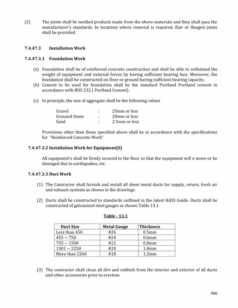
466
(2) Thejointsshallbemoldedproductsmadefromtheabovematerialsandtheyshallpassthe
manufacturer’s standards. In locations where removal is required, flair or flanged jointsshallbeprovided.
7.4.47.3 Installation Work
7.4.47.3.1 Foundation Work
(a) Foundationshallbeofreinforcedconcreteconstructionandshallbeabletowithstandthe
weight of equipment and external forces by having sufficient bearing face. Moreover, thefoundationshallbeconstructedonfloororgroundhavingsufficientbearingcapacity.
(b) Cement to be used for foundation shall be the standard Portland Portland cement inaccordancewithBDS232(PortlandCement).
(c) Inprinciple,thesizeofaggregateshallbethefollowingvalues
Gravel : 25mmorless GrousedStone : 20mmorless Sand : 2.5mmorless
Provisionsotherthanthosespecifiedaboveshallbe inaccordancewiththespecificationsfor“ReinforcedConcreteWork”
7.4.47.3.2 Installation Work for Equipment(S)
Allequipment’sshallbefirmlysecuredtothefloorsothattheequipmentwillomoveorbedamagedduetoearthquakes,etc.
7.4.47.3.3 Duct Work
(1) TheContractorshallfurnishandinstallallsheetmetalductsforsupply,return,freshairandexhaustsystemsasshowninthedrawings.
(2) DuctsshallbeconstructedtostandardsoutlinedinthelatestHASSGuide.Ductsshallbe
constructedofgalvanizedsteelgaugesasshownTable13.1.
Table - 13.1
Duct Size Metal Gauge Thickness Lessthan450 #26 0.5mm 455~750 #24 0.6mm 755~1500 #22 0.8mm 1501~2250 #20 1.0mm Morethan2260 #18 1.2mm
(3) Thecontractorshallcleanalldirtandrubbishfromtheinteriorandexteriorofallductsandotheraccessoriespriortoerection.

467
(4) A flexible connection shall be made between the fan discharge and the adjoining ductwork.
(5) Low-velocityductsshallbeinstalledasfollows:
Table - 13.2 : Duct Flanges
Bolt Rivet
Thickness Shape Steel
Max. Pitch Dia. Pitch Dia. Pitch
0.5mm 25x25x3 3.6m 8.0mm 100mm 4.5mm 65mm 0.6 25x25x3 3.6 8.0 100 4.5 65 0.8 30x30x3 2.7 8.0 100 4.5 65 1.0 40x40x3 1.8 8.0 100 4.5 65 1.2 40x40x5 1.8 8.0 100 4.5 65
Table - 13.4 : Duct Hangers
Thickness Shape Steel Steel Rod Dia. Max. Pitch 0.5mm 25x25x3 9mm 3.0m
0.6 25x25x3 9 3.0 0.8 30x30x3 9 3.0 1.0 40x40x3 9 3.0 1.2 40x40x5 9 3.0
(6) SpiralDuct
(a) The straight portion of the spiral duct shall be fabricated, using a strip of the
galvanized steel sheet. The nominal size of the spiral duct shall be based on theinsidediameter.Thetoleranceininsidediametershallbe+0~+2mminreferencetothenominalsize.ThethicknessoftheironstripstobeusedshallbeasindicatedinTable13.5.
Table - 13.5 : Thickness of Spiral Duct
AirDuctDiameter(mm) Thickness(GaugeNo.)ofironstrips Below200 0.5mm(#26) Over200,butbelow600 0.6mm(#24) Over600,butbelow800 0.8mm(#22) Over800,butbelow1,000 1.0mm(#20)
The pitch of the side seaming at the straight portion of the spiral duct shall be asindicatedinTable13.6andthefoldingwidthshallbeover6mm.
Table - 13.6 : Side Seaming pitch of spiral Ducts
Air Duct diameter (mm) Seam Pitch (mm)
Below100 Below100 Below1,000 Below150

468
(b) Thejointingofonespiralducttoanothershallbepreformedbyapplyingasmanyside seaming as required, using galvanized steel strips or welding as many steelstripsarrangedproperlybetweenspiraljoints.
Thegalvanizedsteelstripsshallbeapplied,inadvance,withrustpreventivepaintonbothinnerandoutersides.
Thenominalsizeofspiralduct jointsshallbebasedontheoutsidediameterof the
spiral duct joints, and the tolerance in nominal size shall be as indicated in Table13.7.
Table - 13.7 : Tolerance in spiral duct Joint Diameter
Nominal Size (mm) Tolerance (mm)
Below600 -1.5-2.5 Over600,butbelow1,00 -2.0-4.0
ThethicknessofthegalvanizedsteelstripstobeusedforthejointbetweenspiralairductsshallbeasindicatedinTable13.8.
Table - 13.8 : Thickness of Galvanized iron Strips and Steel Strips
Nominal Size (mm) Thickness (Gauge No)
Below200 0.6mm(#24) Over200,butbelow600 0.8mm(#22) Over600,butbelow800 1.0mm(#20) Over800,butbelow1,000 1.2mm(#18)
TheoverlappingwidthbetweensteelstripsusedforthespiralductjointshallbeasindicateinTable13.9.
Table : 13.9 : Overlapping width between iron strips or steel strips
Nominal Size (mm) Overlapping Width (mm)
Below125 60 Over125,butbelow300 80 Over300,butbelow1,000 100
(c) Spiralductreinforcement
ThereinforcementforspiralductsshallbeasperTable13.10.
Table : 13.10 : Reinforcement for Spiral ducts
Rivet
AirDuctDiameter(mm) Reinforcinganglesteel
MountingInterval(mm)
Dia.(mm) Pitch(mm)
Over600,butbelow750 30x30x3 Below2,400 4.5 65 Over 750, but below 30x30x3 Below1,800 4.5 65

469
1.200 Over1,210 40x40x3 Below1,200 4.5 65
(7) Airductsupport
(a) Thehangersandsupportsfortherectangularairductshallbemadeofshapesteelorgar steel. The shapes and dimensions of the hangers and supports shall be as perTable13.4
(b) ThehangersandthesupportsforthecircularshangershallbeasperTable13.12.
Table - 13.12 : Shape and dimensions of the hangers and supports for the circular air duct
Hanger
Support
Dia. Of circularairduct
Flat steel(mm)
Max. mountinginterval
Flat Steel(mm)
Max. mountingInterval(mm)
Below1,500 25x3 Barsteelwithasizeof 25x3 or 9mmøbarsteel
2,700 25x3 2,700
Over1,500 30x3 Barsteelwithasizeof 30x3 or 12mmøbarsteel
2,700 30x3 2.700
(8) Acanvassheetshallbeusedfortheconnectionbetweentheairductandtheairbloweror
betweentheairductandtheairexhaustersothatthevibrationsfromtheairblowerortheairexhaustermaynotpropagatetoothers.
(9) Wheretheairductisinstallpenetratingthroughawall,athroughpartbothonthewasside
andtheductsideshallbefinishedtoagoodappearance.(10) Thecheckingaccessportshallbesuchaswillallowthecaseofopeningandclosingandas
will permit air leakage. The access port cover shall be made of the galvanized sheet ironhavingthesamethicknessasthatofthesheetironfortheairduct.Particularly,theaccessportcoverata locationwheretheair fromtheairconditionerflowsshallhaveinsulatingmaterialtothethicknessofmorethan25mm.
(11) After, theinstallation,theinterioroftheairductshallbecleanedthoroughlyandcheckif
thereisnointerferenceintheairflow.(12) Outdoorairintakeandexhaustlouver The outdoor intake louver and exhaust louver shall be made of the stainless steel sheet
havingthethicknessofmorethanno.20gauge. Theeffectiveareaofthelouversshallbeover40%,andthoselouvers,whichareinstalledat
suchlocationswheretheyareexposedtoweathers,shallbedesignedandmanufacturedtobeofsuchaconstructionaswillpreventrainwaterfromgettinginside.
(13) Diffusers

470
(a) Thediffuserstobeusedshallhaveagoodappearance,andtheyshallbynomeansbeallowedtogeneratenoisesduringsystemoperation.Inaddition,thediffusersshallbedesignedtobecapableofprovidingnormalperformance.
(b) UniversalTypediffuser Themountingframeofthediffusersofthistypeshallbefabricatedwithsteeloriron
platehavingathicknessofmorethan1.0mm,anditshallhavesuchaconstructionastheframecanbemountedtotheairductbymeansofbolts.
Thediffuserbladesshallpermitthecaseofadjustment. The shutter to be employed to the universal type diffuser shall be of the double
accessdoortype. Unlessotherwisespecified,thediffuserofanytypeshallbemadeofgalvanizedsteel
sheetandshallbefinishedwithmelamineresinbakedonthesurfaceofeachdiffuserunit.
(c) The anemodiffusers to be used shall be used shall have sufficient air diffusing
performance and they shall be provide with a damper and an air flow informingdevice.
7.4.47.3.4 Piping (1) Coolingmediumpiping
(a) Theinsidesofthepipesshallbethoroughlycleanedanddriedbeforeuse. After cleaning the ends of the pipes shall be sealed by an appropriate method to
preventanforeignmatterfromenteringduringthepipingwork.(b) Thepipesshallbenormallycutperpendiculartothepipecenter.Thecuttingshallbe
suchthatthepipediameterisnotdecreased.Theoutersurfacesofconnectingpipesand the inner surfaces of joints shall be polished sufficiently with a flux brush, etc.Aftertheoutersurfaceofthepipesiscoatedwithflux,theyshallbecarefullyinsertedinthejointsandfitperfectlywhileheating.
(c) The dischargeand intake gas tubes shall have a minimum downwardgradientofat
least1.200.(d) Thepipingshallbeperformedinconsiderationofexpansionandcontraction.(e) In flanged joints, a packing of a thickness within 1.5 mm as specified in JIS R3453
(Compressedasbestossheet)shallbeused.(f) A by- pass between the pipe diameter and the same diameter shall be provided in
coolingmediumfilters,automaticexpansionvalves,coolingmediumsolenoidvalves,etc.
(g) Thepitchforhoistandsupportfixture’sshallbeasshownintable13.3.4.
Table - 13.13 : Copper Pipe support pitch

471
PipesupportpitchNominalDiameter 68121620253240506575100BMax. 1.01.01.01.01.51.51.52.02.52.53.03.0Pitch(m)
(h) Topreventthetransmissionofvibrations,anti-vibrationjoints,andantivibrationhoist
andsupportfixturesshallbeused. 7.4.47.3.5 Insulation Work 7.4.47.3.5.1 Materials(a) The contractor shall furnish and install all insulation materials required for ductwork as
shownintheDrawings.(b) Specificationsforheatinsulationcoverings.
Table - 13.14
Classification of heat insulation covering
Specifications
Heat insulationmaterials
Glass wool heatinsulation
The glass wool heat insulation board shall beshallbeNo.240KstipulatedinJISA9505(GlassWoolHeatInsulationMaterial).
Exteriormaterials Glasscloth The glass clothes shall be the non-alkali plainweaveclothesstipulated inEP21C in JISR3414(Glassclothes)whichhavebeenmade free fromfraying.
Aluminum The glass clothes shall be the flat weave clothesmade of aluminum foil with a thickness of 0.02mmoroverstipulatedinJISH4160(Aluminumand aluminum Alloy foils), to which the plainweaveclothesmadeof13micronglassyarnand200singlefilamentyarnsaccordingtoJISR3414withaunitacrylicresinadhesive.
Table - 13.15
Classification of heat insulation coverings
Specifications
Auxiliary GlassfilamentRivet
The glass filamentmat shall be madeofglass yarn ofmaterials 18 micron of less according to JIS R 3413andhaveaunitmatweightof45gofoverperm2.The

472
rivetshallbemadeof thewashermadeofgalvanizedsteelplatetowhichanailwithalengthtobechangeddepending upon the thickness of heat insulationmaterialsisbuiltin,orthecopperplatednailforspotwelding, and have a strength sufficient to bear theinsulationmaterials.
Steelframe Inprinciple,thesteelframeshallbemadeofsteelplatewith a standard plate thickness of 0.4 mm or over asstipulatedinJISG3302(Galvanizedsheets)
Adhesive In principle, the acrylic emulsion adhesive shall beused for bonding of glass clothes, glass filament matandaluminum glass clothes, and the chloroprene rubberadhesiveshallbeusedforbondingofrivet.
(3) Materialsandproceduresdependinguponthetypesofheatinsulationwork.
Classification of insulation work Order of insulation work Insulationofexposedinterior 1.Rivetting 2.Heatinsulationboardwithathicknessof50mm 3.Cornerpatchandseal-up 4.Adhesive
5.Glassclothes
Indoorconcealing 1.Rivet 2.Heatinsulationboardwithathicknessof25mm 3.Cornerpatchandseal-up
4.Adhesive 5.AluminumGlassclothes
Note : The galvanized steel plate with a thickness of 0.2 mm or over shall be used forcorner patch,andtheglassfilamentmatshallbeusedforseal-up.7.4.47.3.5.2 Execution(1) Themutualclearancebetweentherespectiveinsulationshallnotincludethethicknessof
exteriormaterialsorauxiliarymaterials.(2) The mutual clearance between the respective insulation shall as small possible, and no
overlappingjointsshallbeprovidedonthesameline.(3) Inprinciple,tworivetsshallbedrivenintothelowerandsidesurfacesandonerivetinto
theuppersurfaceoftheairductatintervalsof300mmeach.(4) Theportionorairductpenetratingthroughthefloorshallbecoveredwithstainlesssteel
fromthefloorsurfacetoheightofupto150mminordertoprotecttheinsulation(5) The outermost ends of the insulation shall be protected as required depending upon the
materialsandpurposeofheatinsulation.

473
(6) Heatinsulationworkforinspectiondoors,etc.ofequipmentrequiringsuchinsulationshallbecarriedoutsoasnottocausehindranceduringopeningandclosingofsuchdoors,etc.nordeteriorationofthesaidheatinsulation.
7.4.47.3.6 Painting Work 7.4.47.3.6.1 General(1) Allequipmentandmaterials,exceptforthefollowing,shallbepainted. (a) Surfacesotherthangalvanizedsurfaces (b) Galvanizedportionswhicharenormallyconcealed(2) Allequipmentandmaterialsrequiringinspectionshallbepaintedafterinspection.7.4.47.3.6.2 Painting The types of paints and frequency of painting of the respective portions shall, inprinciple, be as specified in Clause 11.3.5 Unless specified in this table, such painting shall becarriedoutaccordingtosimilaritemstakingintoaccounttheworkpurposes,materialsandotherconditions.7.4.47.4 Tests 7.4.47.4.1 Piping(1) Therefrigeratorshallpasstheair-tightnessandpressurewithstandtests.(2) Therefrigeratorsshallbetestoperatedinthefactoryandcarefulinvestigationsconcerning
performance,noise,vibrations,etc.shallbeperformed.Afteritisconfirmedthatthetestshavebeenpassed,therefrigeratorshallbeshippedafterapplyingrust-proofpaint.
(3) Afterinstallation,therefrigeratorsshallbetestoperated.(4) After completing of the refrigerant piping, an air-tightness test shall be performed using
carbon dioxide, nitrogen, dry air, etc. After the air-tightness test, the entire system shallunder-gohighvacuumevaporationtoremoveallwater.Afterthisdehydrationtreatment,acoolingmediumleaktestshallbeperformedaccordingtotheinspectionoftheEngineer.
7.4.47.4.2 DuctAfter completing the air duct installation, the air duct system shall have and air blow test in thepresence of the Engineer. Unless otherwise specified, all of equipment, materials and executionshallbeasstipulatedin“IndoorLightingSystem”.7.4.48 Secondary-Electrical Wiring 7.4.48.1 General(1) Thecontractorshallfurnishandinstallthecontrolpanels,switches,receptacles,electrical
conduitpipes,wires,outletboxforsecondarywiringequipmentasshownintheDrawings.

474
(2) Motors used in cooling equipment, blowers pumps, etc. shall all be included in this
equipmentwork.(3) Unlessotherwisespecified,thewireconduitandwiringworkintheprimarysideshallall
beperformedasseparateelectricalequipmentwork.However:
(a) Secondary side wire conduit and wiring work for cooling equipment operatingpanelsandbelowshallallbepartoftheworkoftheequipmentconcerned.
(b) Wireconduitandwiringworkrelated to theautomaticcontrolofairconditioning
equipmentshallallbepartoftheworkoftheequipmentconcerned.(c) Insufficientwaterlevelalarmequipmentforwatersupplytanks,etc.shallbeapart
oftheworkoftheequipmentconcerned.(4) Unlessotherwiseindicatedinthisclause,allofequipment,materialsandexecutionshallbe
asstipulatedin“IndoorLighteningPlugandTelephonePipingSystem”7.4.48.2 Equipment And Materials(1) CablesshallbeasshowninTable-14.1.
Table - 14.1(1)
Items CodeNo Type LetterControlcable JISC3401 Polyvinyl ChlorideCVV InsulatedandSheathedcontrol CablesCross-linked JISC3606 Cross-linked Polyethylene CVPolyethylene InsulatedCableCable
(2) TheelectricalequipmentandmaterialsshallmeetthestandardsoftheJapaneseElectrical
manufacturersAssociation(JEM)inadditiontothesespecifications.(3) Motors
(a) Unlessotherwisespecified,ACmotorsshallmeetthespecificationsinTable14.2.
MotorSpecifications JIS4201 Low-Voltage ThreePhaseInductionMotorVoltage 400G Insulationclass E

475
(b) Three-phase induction motors shall be those using the starting equipment in Table14.3.asstandard.
Table 14.3
Area
Capacity(kw) Refrigerating
equipment Blowers
Motor Startingsystem Motor Startingsystem
37ormore Highvoltagewoundtype
Resister Highvoltagewoundtype
Resister
15~37 Lowvoltagespecial
Y-A Lowvoltagespecialsquirrel
Y-A
11~15 Lowvoltagespecialsquirrel
Y-A Lowvoltagespecialsquirrel
Y-A
5.5~7.4 Lowvoltagespecialsquirrel
Directstarting Lowvoltagespecialsquirrel
Directstarting
37orless Lowvoltagenormaltype
Directstarting Lowvoltagenormaltype
Directstarting
7.4.48.3 Test
Uponcompletionofthework,thewholesystemshallbeprovedacceptablebyinspectionscarriedoutbytheEngineer.
7.4.49 Lighting, Plug and Telephone Piping System Principle of Lighting
Theessentialfeaturesofanefficientlightingsystemare:
- visual comfort through adequate illumination of the working surface, prevention of
glare,andavoidanceofshadows,
- easeofmaintenance.
Thedesignofalightingsystemshallinvolve:
a) carefulplanningofthebrightnessandcolourpatternwithinboththeworkingareasand
thesurroundingsso thatattention isdrawnnaturally to the importantareas,detail is
seenquicklyandaccurately,andtheroomisfreefromanysenseofgloomormonotony,
b) useofdirectionallightingtoassistperceptionoftaskdetail,
c) controllingdirectandreflectedglarefromlightsourcestoeliminatevisualdiscomfort,
d) minimizing flicker from certain types of lamps and paying attention to the colour
renderingpropertiesofthelight,
e) the correlation of lighting throughout the building to prevent excessive differences
betweenadjacentareas,soastoreducetheriskofaccidents,and
f) theinstallationofemergencylightingsystems,wherenecessary.

476
7.4.49.1 Scope of Work
ConcealedElectricalwiringbyEastern/BRBcableorequivalent EuropeanMadeMKtypeGangswitch,socketMCBetc ProvisionforInternetfacilitiessystem,Telephone&Intercomwiring. SufficientEarthlingsfacilities. TobeusedLEDLight.
Thescopeofworkunderthecontractincludessupplyandinstallationoflightingfixtures,lightingpanel,switches, receptacles,electricalconduitpipes,wires,outletboxes for telephones, internet,dishcableandothernecessaryaccessoriesfortheindoorlightingsystem.7.4.49.2 Design Conditions 7.4.49.2.1 Illumination Level 1) TheilluminationlevelsforeachroomshallbeasshowninTable-15.2.1.
Table - 15.2.1
Name of Room Normal condition Emergency condition Control 500lx 50lx Office 300lx 10lx Relay 300lx 10lx PLC/SCADA 500lx 50lx Conference 300lx 10lx Battery 100lx 5lx RectifierSet 100lx 5lx Corridor 100lx 5lx PumpControl 100lx 5lx CableControl 50lx 5lx B/G 200lx 5lx Lavatory 100lx - Kettle 100lx -
(2) SettingHeight (a) Lightingfixtures RefertoDesignDrawings. (b) Switches 1.25metersabovethefloorlevel,unlessotherwisespecified. (c) Receptacles 0.3metersabovethefloorlevel,unlessotherwisespecified.(3) Powersourcevoltage

477
(a) Forlightingpanel AC3phase4wires415/230V50Hz DC2Wires110V (b) Fornormallighting,convenientoutletandventilationequipment. AC1phase2wires220V50Hz (c) Foremergencylighting DC2Wires110V7.4.49.3 System Description(1) AC,DCSourceandearthlingshallbesuppliedfromtheprimaryside.(2) StandardLEDLampsshallbeprovidedforthecontrolroomandallmiscellaneousrooms,
andshallbedesignedtobemanuallyactivatedbymeansoftheswitchesattheentranceofeachroom.Thelampsinthecorridor,Toiletroom,officeandallelectricalroomsshallbesensorbasedwhichwillautomaticallyswitched“ON”andoff.
(3) LEDLamp/Incandescentlampsshallbeprovidedinallpartsofthecontrolbuildingtoserveas emergency lighting. The lamps in the control room, corridor, office and all electricalroomsshallbeautomaticallyswitched“ON”incaseofACfailure.
(4) Outlet boxes for telephones shall be provided for the control room, together with piping
from the outlet boxes to the cable tray in the cable control room. The sitting of thetelephonesandwiringshallbeincludedintheelectricalscopeofworkofLotIV.
(5) Exitsignlight Theexitsignlightsshallbemountedabovetheallexitsofthecontrolbuilding.(6) Spareparts,asindicatedbelow,willbesuppliedforthree(3)yearsnormaloperation.7.4.49.4 Equipment’s and Materials 7.4.49.4.1 Wires WiresshallbeasshownintheTable15.4.1
Table - 15.4.1 Item Code No. TypeLetterVinylwireJISC3307 600GradePolyvinyl IV ChlorideInsulatedWiresHeat-resistant JISC3317 Heat-resistantvinyl HIV Insulatedwire

478
HIVwiresshallbeusedintheDCcircuit.7.4.49.4.2 Wire ConnectorsWireconnectorsforindoorwiringshallbeinaccordancewithJISC2810orequivalentBDS7.4.49.4.3 Metal Conduit and FittingsMetalconduitandfittingsshallbeinaccordancewiththeTable15.4.3,andtheconduitshallbeofheavygaugetype.
Table 15.4.3 Item Code No. Designation Conduit JISC8305 Rigid metalConduit (heavygauge)Coupling JISC8330 Coupling forRigidMetalConduitNormalBend JIS C8330 ElbowsforRigidMetalconduitBushing JISC8331 BushingforRigidmetalConduitLocknut JISC8333 Locknuts forRigidMetalConduitSaddle JISC8334 SaddlesforRigidMetalConduitUniversal JISC8335 Universal Fittings for Rigid metal
Conduit
OutletBox JISC8337 Out Boxes forRigidmetalConduitSwitchBox JISC8337 Switch Boxes forRigidMetalConduitConcreteBox JISC8338 Concrete Boxes forRigidMetalConduitBoxCover JISC8339 Box covers forRigidMetalConduitInsulatedBushing JISC8347 Insulated Bushing for
rigidMetalConduit

479
7.4.49.4.4 Pull BoxesPullboxesshallbemadeofsteelandcoatedwithprotectivepaint,andwhereverexposedtoview,shallbecoatedwithafinishpaintofacolorapprovalbytheEngineer. 7.4.49.4.5 Wiring DevicesWiringdevicesshallbeinaccordancewiththeTable-15.4.5
Table-15.4.6
Items CodeNo. DesignationFluorescentLamp JISC7601 Fluorescent Lamps for GeneralLightingServiceRapidStartJISC7602 Instantaneous Start Hot cathode Discharge
Fluorescent Lamps(40Wtype)
GlowStarterJISC7607 GlowstartersforfluorescentLamps(Lessthan40
Wtype
Fluorescentfixture JISC8106 Lighting Fitting for FluorescentLamps ballastsforFluorescentlampsIncandescentlamp JISC7501 Double Filament Lamps forGeneralUse

480
7.4.49.4.6 Lighting Fixtures(a) InPrincipleshapesanddimensionsshallbeinaccordancewiththeDrawings.Catalogsand
shopdrawingsshallbesubmittedtotheEngineerforapproval.(b) Lighting fixtures for emergency use shall be as specified by BCJ (Articles rated by the
BuildingCenterofJapan),orapprovedequal. 7.4.49.4.7 Lighting Panel Shapes, electrical characteristics, types capacities of circuit breakers, and the system ofoperationshallbeinaccordancewiththeDrawings. Thepanelshallmadeofsteelplatewithathicknessofmorethan1.6mm(body)and2.3mm(door)respectively. The finish shall be painted with a color approved by the Engineer. Catalogs and shopdrawingsshallbesubmittedtotheEngineerforapproval.7.4.49.4.8 Over Current ProtectorsMoldedcasecircuitbreakersandresidualcurrentprotectivedevicesshallbeofEuropeanStandardusedinthelightingpanel7.4.49.5 Indoor Wiring 7.4.49.5.1 Rigid Metal Conduit(1) Installation
(a) Imbeddingorconduitlayingshallbesomadethatthestrengthandstructureofthebuildingisnotaffected.
(b) Cutendsofconduitshallbeneatlyandsmoothly finishedby instrumentsuchasa
reamer.

481
(c) Conduitshallbebentataradiusofmorethansix(6)timestheinternaldiameteroftheconduitconduitrunningbetweenoutletsandpullingboxesshallnothavemorethantheequivalentoffour90obends.
(d) Apullboxorjunctionboxshallbeinstalledtoprotectconduitexceeding30meters
inlengthandatthepointsrequired.(e) In general, a switch or outlet box shall be used at all points where a switch,
receptacle(socket)orlightingfixtureistobeprovided.(f) Where low voltage metal conduit is enclose in proximity to or crosses
communication wiring,metallicwater pipeor gaspipe, the workshall be so donethatdirectcontactisavoided.
(2) Connectionofconduits
Conduitand fittingsshallbeperfectlyconnected,bothphysicallyandelectrically,andtheconductorresistanceshallbepreferablydeptwithin2ohmsbetweengroundingconductorandtheendmetalconduit.
(3) PullBoxesandJunctionBoxes
(a) Shapeandtypeoftheseboxesshallsuittheplaceofinstallationandasteelplateormorethan1.2mminthicknessshallbeused.
(b) Boxes shall have adequate dimensions well matching the number or conduits
connectedandtheconditionofconnectingorpullingwires.(c) Wheretheboxiscoveredorconcealedinstructuralmaterial,accesstotheboxshall
bemadepossibletofacilitateinspection.(4) Installationoffeederconduits
(a) Exposedmainconduitshall,inprinciple,runparallelwithwallorceiling.(b) Metalssupportsforconduitinconcretebuildingshallhaveaproperfixinginsertor
boltpreviouslyembeddedintheconcrete.(c) Spacing between metal inserts or bolts to support conduit shall in principle, be
approximately2meters.(5) Painting,ProtectionandcleaningofConduit
(a) Wheretheplatedorpaintedsurfaceofconduit,metalsupportorboxhaspeeledoff,itshallbetouchedupwithprotectivepaint.

482
(b) Conduitshallbesufficientlyprotectedagainstentryofmoisture,water,dustetc.and
thecutendofconduitshallbebushbecapped,woodpluggedorcoveredwithrag,etc.Wheneverconcreteworkisinprogress.
(c) Conduitandboxesshallbewellcleanedandtheconductivitycheckedafterremoval
oftheforms.
(6) WirePulling
(a) Connection of wire shall not be made inside metal conduit. Connection shall bemadeinmetalbox,junctionboxordistributionboard.
(b) Wire shall be pulled through conduit after the inside of conduit has been cleaned
and when each of conduit has been capped with bushing. Cleaning shall beperformed in such a manner that walls, ceilings, etc. around the conduit are notstainedorspoiledinanyway.
(c) Inallcases,allwiresstemmingfromonecircuitshallbeaccommodatedinthesame
conduit for A.C circuit work, except where a balanced condition is electro-magneticallyattainedbyaccommodatingbothlinesofthesamepolaritywithinthesameconduit.
7.4.49.6 Installations 7.4.49.6.1 Installation of Lighting Fixtures(a) Heavylightingfixturesshallbefirmlysupportedusinginserts,studsorbolts,attachments
andifnecessaryshallbeprovidedwithameanstopreventswingingbyusingwoodscrew,etc.
(b) Lightingfixturesshallbeinstalledhorizontallyorverticallyinaworkmanlikemannerand
shallbesolocatedastonotinterferewithinspectionofrelatedequipment.7.4.49.6.2 Installation of Lighting PanelLightingpanelshallbe installedfirmlyonwallsorothersurfacesinaworkmanlikemanner,andshallbesolocatedastonotinterferewithinspectionofrelatedequipment.

483
7.4.49.6.3 TestAperformancetestshallbemadebemadeafterinstallationofequipmenthasbeencompleted.7.4.49.7 Grounding 7.4.49.7.1 Grounding ResistanceGroundingresistanceshallbe10ohmsonless,unlessotherwisespecified.7.4.49.7.2 Electrical Works to Be GroundedExceptforspecificinstances,allelectricalthattherespectivegroundingresistancevaluesarekeptatspecifiedvaluesthroughouttheyeardespiteseasonalchanges.(a) Nogroundingisrequiredforsteelbase,metalboxandsteelframeofequipmentisoperated
onlessthanAC150V(Voltagetoground)andisinstalledatadrylocation.(b) Metalconduitandmetalaccessories(c) Metal enclosure accommodating the discharge lamp ballast and the metal parts or a
discharge lamp lighting fixture, except where grounding is required and/or when sodirectedbyEngineer,shallbegrounded.
7.4.49.7.3 Sign, Signal & Annotation: ●IntegratedDesignofDifferentkindofIndicatorslike-AcrylicSignBoard,LEDSignBoard,NeonSignBoard,ReceptionSignBoard,SafetySign,PVCLetters,GlowSignBoard,CustomizedDisplay Boards,OverheadSignage,MetalNameplates,CommercialSignBoards,OutdoorSigns,ElectronicSignBoardsetc.shouldbeprovidedinthedesign&construction.●DigitalLEDSignboardwiththefeaturesofexcellentvisibility(evenindaylight);Goodqualityatreasonablepriceandlightweight;Simpleinstallation,Safetotouchandclean;Changingcolorforattractingattention;Extremelylowpowerconsumption.●ShouldbeprovidedtheAccessorieslikeAdaptorandchainsetc.LEDdisplayscreenshallbeminimum1.0squaremeter.ShallbeCompatiblewithIP65.ShallbeinstalledatthefrontsidewallofthebuildingEnvironmentallyfriendlydisplayitensureslowerpowerconsumptionandlongerlifetime.