7779920 rev: a - commscope.com · 1 1 brce rod attachment bracket 1 1 m12 x 35lg hex hd screw, stl,...
TRANSCRIPT

7779920R
ev: A

This document is for the following:HX6/USX6-*** 1.8m ANTENNA
7779920
DRE03
Bulletin
RevStatusModel Version
Version RevStatus
2 of 29page
Installation InstructionsARE00
Andrew SolutionsCustomer Service 24 hoursU.S.A., Canada, Mexico: 1-800-255-1479 or 1-888-235-5732 U.K.: 0800 250055Other Europe: +44 592 782 612
www.commscope.com\andrewVisit our Web site at www.commscope.com\andrew or contact your local Andrew Solutions representative for more information.© 2008 CommScope, Inc. All rights reserved.Andrew Solutions is a trademark of CommScope. All trademarks identified by ® or ™ are registered trademarks or trade-marks, respectively, of CommScope. This document is for planning purposes only and is not intended to modify or supplement any specifications or warranties relating to Andrew Solutions products or services.
Notice: Andrew disclaims any liability or responsibility for the results of improper or unsafe installation, inspection, maintenance, or removal practices.Aviso: Andrews no acepta ninguna obligacion ni responsabilidad como resultado de practicas incorrectas o peligrosas de instalacion, inspecci6n, mantenimiento o retire.Avis : Andrew decline toute responsabilite pour les consequences de procedures d'installation, d'inspection, d'entretien ou de retrait incorrectes ou dangereuses.Hinweis: Andrew lehnt jede Haftung Oder Verantwortung fur Schaden ab, die aufgrund unsachgemaBer Installation, Uberprufung, Wartung Oder Demontage auftreten.Atencao: A Andrew abdica do direito de toda responsabilidade pelos resultados de praticas inadequadas e sem seguranca de instalacao, inspecao, manutengao ou remocao.Awertenza: Andrew declina eventual! responsabilita denvanti dell'esecuzione di procedure di installazione, ispezione, manutenzione e smontaggio improprie o poco sicure.
HX6 & USX6 6ft (1.8m) Antennas

This document provides assembly instructions for a HX6/USX6 antenna.
The antenna can be mounted to the left or to the right of the supporting structure.
These instructions describe how to mount the antenna to the left of the supporting structure,however instructions showing the antenna mounted to the right of the supporting structure areincluded where appropriate. It is recommended that at least 2 persons assemble the antenna.
INTRODUCTION
Page 3 of 297779920
CONTENTS & INTRODUCTIONSECTION 1INSTALLATION
INSTRUCTIONS

Page 4 of 297779920
SAFETY INSTRUCTIONSSECTION 2INSTALLATION
INSTRUCTIONS

Page 5 of 297779920
SAFETY INSTRUCTIONSSECTION 2INSTALLATION
INSTRUCTIONS

Table 1 Supplied Equipment and ToolsPage 6 of 29
7779920EQUIPMENT AND TOOLS
SECTION 3INSTALLATION INSTRUCTIONS
Item Qty Description Contained in Kit Part NoHX6 USX6
A 1 1 ReflectorB 1 1 Shield SetC 1 1 RadomeD 1 1 Feed (frequency dependant)
D1 Feed Hardware Kit Contained in D4 4 M6 x 20lg SHCS, sst, pass4 4 M6 Lock Washer, sst, pass1 1 Conductive Grease (tube)2 2 Gloves
D2 Vertex Plate Kit Contained in D2 2 Vertex Plate4 4 M4 x 10lg SHCS, sst, pass
E 1 1 Elevation Pivot Bar - TopF 1 1 Vertical Support ChannelG Mount Kit
G1 1 1 Elevation Pivot Bar - Bottom Contained in GG2 3 3 Spacer Plate Contained in G
G3a 1 1 Elevation Pivot Bracket - Top Right Contained in GG3b 1 1 Elevation Pivot Bracket - Top Left Contained in GG4 1 1 Elevation Pivot bracker - Bottom Contained in GG5 1 1 Safety Bracket Contained in G
H Shield and Mount Hardware kitH1 Shield Hardware Kit Contained in H
62 78 M6 x 20 Hex Hd Screw, sst, pass124 156 M6 Washer, sst, pass62 78 M6 Lock Washer, sst, pass62 78 M6 Nut, sst, pass
H2 40 40 M6 x 25 Skt Hd Cap Screw, sst, pass40 40 M6 Large Washer, sst, pass
J Mount Hardware Kit Contained in HJ1 3 3 M16 U-Bolt c/w Nuts & WashersJ2 4 4 M12 x 40lg Carriage Bolt
4 4 M12 Nut, stl, galv4 4 M12 Lock Washer, stl, galv4 4 M12 Washer, stl, galv4 4 M16 Washer, stl, galv
J3 1 1 M16 Eye Bolt, stl, galv2 2 M16 Washer, stl, galv2 2 M16 Nut, stl, galv1 1 M12 x 45lg Hex Hd Screw, stl, galv1 1 M12 Lock Washer, stl, galv1 1 M12 washer, stl, galv1 1 M12 Nut, stl, galv
J4 2 2 M16 x 45lg Hex Hd Screw, stl, galv2 2 M16 Lock Washer, stl, galv4 4 M16 Washer, stl, galv2 2 M16 Nut, stl, galv
J5 9 9 M10 x 35lg Hex Hd Screw, sst, pass9 9 M10 Lock Washer, sst, pass9 9 M10 Washer, sst, pass

Table 1 Supplied Equipment and Tools
Page 7 of 297779920
EQUIPMENT AND TOOLSSECTION 3INSTALLATION
INSTRUCTIONS
Item Qty Description Contained in Kit Part NoK HX6 USX6 Strut Hardware Kit Contained in H
K1 1 1 Spacer Plate1 1 Brce Rod Attachment Bracket1 1 M12 X 35lg Hex Hd Screw, stl, galv1 1 M12 Lock Washer, stl, galv1 1 M12 Washer, stl, galv3 3 M10 x 35lg Hex Hd Screw, sst, pass3 3 M10 Lock Washer, sst, pass3 3 M10 Washer, sst, pass
K2 1 1 Azimuth Adjuster (supplied assembled) Contained in HL 1 1 Brace Rod
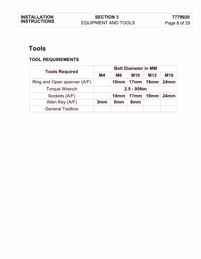
TOOL REQUIREMENTS
Tools
Page 8 of 297779920
EQUIPMENT AND TOOLSSECTION 3INSTALLATION
INSTRUCTIONS
Tools RequiredBolt Diameter in MM
M4 M6 M10 M12 M16Ring and Open spanner (A/F) 10mm 17mm 19mm 24mm
Torque Wrench 2.5 - 95NmSockets (A/F) 10mm 17mm 19mm 24mm
Allen Key (A/F) 3mm 5mm 8mmGeneral Toolbox

A
B
C
D2
D
D1
Page 9 of 297779920
EQUIPMENT AND TOOLSSECTION 3INSTALLATION
INSTRUCTIONS

J1
J2
J4
J5
J3
K1
K2
G1
G2
G4G3a
G5
G3b
H1
H2
L
E F
Page 10 of 297779920
EQUIPMENT AND TOOLSSECTION 3INSTALLATION
INSTRUCTIONS

A
Page 11 of 297779920
UNPACKINGSECTION 4INSTALLATION
INSTRUCTIONS
Instructions for unpacking crate:Wire bound crate:1. Release wire tabs at one side of the crate.2. The crate panel will hinge open along the opposite side from the released wire tabs.Nailed crate:1. Carefully remove panel to allow access to shields and reflector struts.Remove components:3. Remove shields, strut and integration/omt kit.4. Remove nails from top of packing strut, the reflector can then be hinged backwards along the bottom edge and removed from the crate, handle reflector CAREFULLY at all times.5. Leave reflector attached to the backing struts until instructed to remove.6. Remove radome and feed.7. Open kit boxes and remove components as required.
Handle reflectorCAREFULLY atall times
Leave packing struts in place duringassembly until directed to remove.(omitted on subsequent views for clarity)
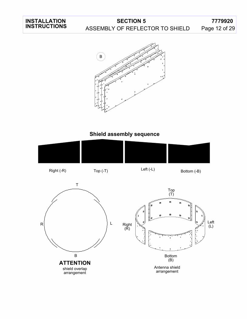
Shield assembly sequence
Right (-R) Top (-T) Left (-L) Bottom (-B)
B
Top(T)
Left(L)Right
(R)
Bottom(B)
Antenna shieldarrangement
shield overlaparrangement
T
B
R L
ATTENTION
Page 12 of 297779920SECTION 5INSTALLATION
INSTRUCTIONS ASSEMBLY OF REFLECTOR TO SHIELD

H1Flat
washers
Lockwasher
Threaded insertsfor radomeattachment
Drain hole
Reflector attachment
slots
Drain hole
Insert shield in to reflector so that attachment slotsalign with rim holes in reflector
Ensure highest side ofshield set is aligned to
top of antenna
Align shield slots and reflectorholes to install bolt and washer.Repeat at 90 degree intervals.
Fit flat washers, lock washerand nut and finger tighten.
H1
Flatwashers
Lockwasher
Page 13 of 297779920SECTION 5INSTALLATION
INSTRUCTIONS ASSEMBLY OF REFLECTOR TO SHIELD
Align red tape onreflector with
red tape on shield

Fit bolts, washers, lock washers and nuts toremaining holes of assembly and tighten.
Tighten all shield and segment fasteningsto 7.7Nm 5%
H1
Page 14 of 297779920SECTION 5INSTALLATION
INSTRUCTIONS ASSEMBLY OF REFLECTOR TO SHIELD

D1
Finger tighten 6-off flanged screws(fully tightened on final alignment)
Page 15 of 297779920SECTION 6INSTALLATION
INSTRUCTIONS FEED ATTACHMENT AND ALIGNMENT
REFER TO SAFETY NOTE ON PAGE 5
Prior to feed attachment, carefully tilt antenna upright using packing struts and hold in position.Do not apply excessive weight toantennas assembly.
Align timing slot in adaptorplate with notch in hubmounting ring casting

D2
Do not removefoam absorber wrap
Tighten to 2.5Nm 5%
D
Page 16 of 297779920SECTION 6INSTALLATION
INSTRUCTIONS FEED ATTACHMENT AND ALIGNMENT
Vertex Plate Assembly
Leave the feed in it's protectivepackaging until ready to install in antenna.
Do not removeprotective tapeuntil ready toinstall OMT
Do not removefoam absorber disc

D
D1
Torque M6 screws to 7.7Nm 5%D1
Page 17 of 297779920SECTION 6INSTALLATION
INSTRUCTIONS FEED ATTACHMENT AND ALIGNMENT
After assembly, remove excess grease from internal reflector surface.
Apply grease tosurfaces indicated
(6GHz to 15GHz only)Align spring pin in feed hubwith slot in adaptor plate.

Unfold radome on to aclear, flat and dry surfaceand assemble radome rim
tensioners at 8 places.
Lift radome andsecure tabs over
hooks
Ensure radome tensionersare pressed fully home.
(When fully pressed home,tensioners are no longer
loose or removable)
H2
Align a radome tensionerwith a shield assembly seam.
Torque to 7.7Nm 5%
Assemble radome to shieldswith screws and washers
Page 18 of 297779920SECTION 7INSTALLATION
INSTRUCTIONS RADOME ATTACHMENT
After feed attachment, carefullylay antenna flat.

USX6 Antennaassembled to leftof support structure
HX6 Antennaassembled to rightof support structure
Page 19 of 297779920SECTION 8INSTALLATION
INSTRUCTIONS MOUNT ATTACHMENT AND ALIGNMENT
Prior to assembly of mount to antenna, determine thedesired installation configuration.

J5
G2
G3b G3a
G4
G2
G2
Loosely tighten all screws untilmount has been fully assembled.
Top of antenna(red tape)
Mount bracket orientation for mounting antennato the left of the support structure
For mounting the antenna to the right of the supporting structureassemble bracket G4 along with associated plate G2 in position indicated.
G3b G3a
G4
G4 & G2 position for left side installation
Page 20 of 297779920SECTION 8INSTALLATION
INSTRUCTIONS MOUNT ATTACHMENT AND ALIGNMENT
Carefully lay antenna on clear, flatground and remove packing struts..Do not apply excessive weight toantennas assembly.

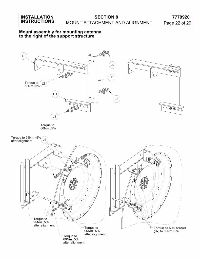
J2
J2
E
F
G1
Torque to60Nm 5%
Torque to60Nm 5% J2
J2
J4 Torque to 95Nm 5%after alignment
J3Torque to95Nm 5%after alignment
Torque to95Nm 5%after alignment
Torque to60Nm 5%after alignment
Torque all M10 screws(9x) to 38Nm 5%
Page 21 of 297779920SECTION 8INSTALLATION
INSTRUCTIONS
Mount assembly for mounting antennato the left of the support structure
MOUNT ATTACHMENT AND ALIGNMENT
J2
J2
E
F
G1
J2
J2Torque to60Nm 5%
Torque to60Nm 5%
J4Torque to 95Nm 5%after alignment
J3
Torque to95Nm 5%after alignment
Torque to95Nm 5%after alignmentTorque to
60Nm 5%after alignment
Torque all M10 screws(9x) to 38Nm 5%
Page 22 of 297779920SECTION 8INSTALLATION
INSTRUCTIONS
Mount assembly for mounting antennato the right of the support structure
MOUNT ATTACHMENT AND ALIGNMENT

K1
L
Torque to38Nm 5%
Torque to60Nm 5%
Large hole forM12 screw
Small hole forM10 screw Torque to
38Nm 5%
Strut bracket K1 can be installedrotated within 360
Page 23 of 297779920SECTION 8INSTALLATION
INSTRUCTIONS MOUNT ATTACHMENT AND ALIGNMENT
Strut to be fitted after Antenna ishoisted to desired position.
Strut to be loosely fitted until alignment is complete then tighten all fixings to torque
specified.

Ensure brackets and nuts arebolted rigidly together as shown with no visible threads.(Viewed from underside for clarity)
Structural Member(Circular)
Torque to95Nm 5%after alignment
K2
Torque to60Nm 5%after alignment
Torque to60Nm 5%after alignment
ATTACHMENT TO CIRCULAR STRUCTURAL MEMBERS.
Torque to60Nm 5%prior to alignment
Page 24 of 297779920SECTION 8INSTALLATION
INSTRUCTIONS
Clamps must be attached to a circular structural member (Dia 48mm - 120mm)capable of supporting 6187N in accordance with TIA-222.
The maximum allowable relative deflection between the antenna mounting pipeand the strut attachment point must be less than 2mm at survival windspeed of the antenna.
MOUNT ATTACHMENT AND ALIGNMENT

Torque to95Nm 5%after alignment
Torque to60Nm 5%after alignment
Torque to60Nm 5%after alignment
Structural Member(Non-Circular)
K2
Torque to60Nm 5%prior to alignment
Ensure brackets and nuts arebolted rigidly together as shown with no visible threads.(Viewed from underside for clarity)
Page 25 of 297779920SECTION 8INSTALLATION
INSTRUCTIONS
Clamps must be attached to a non-circular structural member capable of supporting 6187N in accordance with TIA-222.
The maximum allowable relative deflection between the antenna mounting pipeand the strut attachment point must be less than 2mm at survival windspeed of the antenna.
MOUNT ATTACHMENT AND ALIGNMENT
ATTACHMENT TO NON-CIRCULAR STRUCTURAL MEMBERS.

Attach safety bracket
Torque to95Nm 5%
J1G5
J1
J1
Torque to95Nm 5%after alignment
SUGGESTEDHOISTING
Red tape
Page 26 of 297779920SECTION 8INSTALLATION
INSTRUCTIONS
NEVER WALKUNDER HOISTEDLOADS
MOUNT ATTACHMENT AND ALIGNMENT
Torque to95Nm 5%after alignment

A
Keep safety bracketfully torquedat all times.
Azimuth adjustment
BElevation adjustment
To adjust azimuth releaseand tighten M16 nuts indicatedTighten to 95Nm 5% oncompletion os alignment
To adjust elevation releaseand tighten M16 nuts indicatedTighten to 95Nm 5% oncompletion os alignment
Ensure all hardware is tightened to specified torqueafter completion of azimuth and elevation alignment
Torque M10 screwsto 38Nm 5%after alignment
Torque M12 hardwareto 60Nm 5%after alignment
Torque M12 U-boltto 60Nm 5%after alignment
Torque all M10 screwsto 38Nm 5%after alignment
Torque M16 hardwareto 95Nm 5%after alignment
Torque M16 U-boltsto 95Nm 5%after alignment
MOUNT ATTACHMENT AND ALIGNMENTINSTALLATION INSTRUCTIONS
SECTION 8 7779920Page 27 of 29
Azimuth Adjustment

*25
* 25
*25
*
25
* Angle may be limited by direct mount radio equipment
Limits of strut positionfor attachment totower member
IDEAL = 0
MAXIMUM = 25
View show below is intended as a guide for strut alignment.Strut must be attached to appropriate structural mounting point.Strut angle must not exceed maximum specified.Failure to install the strut as instructed may result in mechanical failure of the antenna.
Page 28 of 297779920SECTION 8INSTALLATION
INSTRUCTIONS MOUNT ATTACHMENT AND ALIGNMENT

Page 29 of 297779920
GENERAL INFORMATIONSECTION 9INSTALLATION
INSTRUCTIONS