777f
TRANSCRIPT

SERV7106-04April 2006Vol. 4, No. 3
TECHNICAL PRESENTATION
777F (JRP)OFF-HIGHWAY TRUCKS
New Product Introduction(NPI)
GLOBAL SERVICE LEARNING

777F (JRP) OFF-HIGHWAY TRUCKSAUDIENCE
Level II - Service personnel who understands the principles of machine system operation,diagnostic equipment, and procedures for testing and adjusting.
CONTENT
This presentation provides new and different New Product Introduction (NPI) information forthe 777F Off-Highway Trucks. This presentation may be used for self-paced and self-directedtraining.
OBJECTIVES
After learning the information in this presentation, the technician will be able to:
1. located and identify the new components2. explain the operation of the new components in the systems3. trace the flow of oil or air through the new systems
REFERENCES
"777D Update (AGC) Off-highway Truck SERV1721
Estimated Time: 8 hrsIllustrations: 90Handouts: 1Form: SERV7106-04Date: 04/06
© 2006 Caterpillar Inc.

TABLE OF CONTENTS
INTRODUCTION ........................................................................................................................5
OPERATOR’S STATION.............................................................................................................8Machine Controls....................................................................................................................9Monitoring System ...............................................................................................................16
ENGINE......................................................................................................................................23Cooling System.....................................................................................................................36
POWER TRAIN HYDRAULIC SYSTEM................................................................................38Power Train Components .....................................................................................................39Power Train Electronic Control System...............................................................................48
STEERING SYSTEM ................................................................................................................50
HOIST HYDRAULIC SYSTEM ...............................................................................................57Pressure Taps For The Hoist System....................................................................................62
BRAKE SYSTEM ......................................................................................................................63
CONCLUSION...........................................................................................................................77
SERV7106-04 - 3 - NPIVol. 4, No. 3, 2006

NOTES
SERV7106-04 - 4 - NPIVol. 4, No. 3, 2006
INTRODUCTION
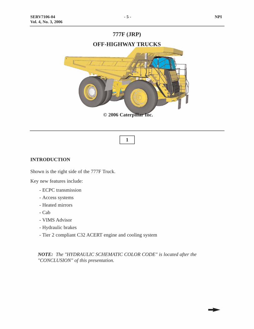
Shown is the right side of the 777F Truck.
Key new features include:
- ECPC transmission- Access systems- Heated mirrors- Cab- VIMS Advisor- Hydraulic brakes- Tier 2 compliant C32 ACERT engine and cooling system
NOTE: The "HYDRAULIC SCHEMATIC COLOR CODE" is located after the"CONCLUSION" of this presentation.
1
SERV7106-04 - 5 - NPIVol. 4, No. 3, 2006
777F (JRP)
OFF-HIGHWAY TRUCKS
© 2006 Caterpillar Inc.

Specifications for the 777F Truck are:
- Serial No. Prefix: JRP- Empty weight: 48581 kg (107104 lbs.)- Load carrying capacity: 90 metric tons (100 tons)- Gross Machine Weight (GVW): 163293 kg (360000 lbs.)- Width: 6.05 m (19.8 ft.)- Height: 5.03 m (16.5 ft.)- Gross Power: 758 kW (1016 hp)
SERV7106-04 - 6 - NPIVol. 4, No. 3, 2006

2
Similarities and Differences
The hoist system and steering system function similar to the 777D. The rest of the machinesystems have significant changes.
SERV7106-04 - 7 - NPIVol. 4, No. 3, 2006
SIMILARITIES AND DIFFERENCES
FEATURES DIFFERENT SIMILAR SAME
Machine AppearanceOperator's StationEnginePower TrainHoist SystemSteering SystemBrake SystemMonitoring SystemAir SystemMaintenance Items
X
X
XXX
X
X
XX
X

OPERATOR’S STATION
The operator’s station for the 777F Off-highway trucks has changed from the previous 777D.
The machine controls are displayed in the following text.
3
4
SERV7106-04 - 8 - NPIVol. 4, No. 3, 2006

Machine Controls
The engine shutdown switch (1) is used for stopping the engine from the ground.
The switch (2) is used for turning on the stairway lights.
5
SERV7106-04 - 9 - NPIVol. 4, No. 3, 2006
1 2

Located on the left side of the dash are:
- Dash panel switch for access lights (1)
- Head lamp switch (2)
- Hazard switch (3)
- Panel light intensity switch (4)
- Intermittent wiper/washer, turn signal control and dimmer switch (5)
- Telescopic/tilt steering column adjustment lever (6)
6
SERV7106-04 - 10 - NPIVol. 4, No. 3, 2006
1 2 3 4 5
6

Located on the right side of the dash are:
- Automatic retarder control (1)
- Front Brake switch (2). The front brake switch allows the operator to turn the front brakeson or off. This switch should be in the on position during normal operation. The dry frontbrakes are optional.
- Advisor system (3)
- Secondary steering and parking brake release switch (4). Normally, when this switch isdepressed, the steering system receives secondary steering oil and the parking brakerelease oil flows to the tank. When the brake release diverter (towing) valve spool isshifted, this switch will also release the parking brakes and provide hoist pilot oil forlowering the body on trucks with a dead engine. This switch also serves as a manualengine pre-lube.
- Manual retarder control lever (5)
- Engine key start switch (6)
- Fan speed switch (7)
- Temperature variable knob (8)
- Air conditioning on/off switch (9)
- Cigarette lighter (10). The cigarette lighter socket receives a 24 volt power supply. A 12volt power supply and an additional 24 volt supply are provided behind the buddy seat.
7
SERV7106-04 - 11 - NPIVol. 4, No. 3, 2006
1 2 3
4
5 6 7 8 9 10
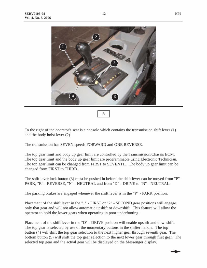
To the right of the operator's seat is a console which contains the transmission shift lever (1)and the body hoist lever (2).
The transmission has SEVEN speeds FORWARD and ONE REVERSE.
The top gear limit and body up gear limit are controlled by the Transmission/Chassis ECM.The top gear limit and the body up gear limit are programmable using Electronic Technician.The top gear limit can be changed from FIRST to SEVENTH. The body up gear limit can bechanged from FIRST to THIRD.
The shift lever lock button (3) must be pushed in before the shift lever can be moved from "P" -PARK, "R" - REVERSE, "N" - NEUTRAL and from "D" - DRIVE to "N" - NEUTRAL.
The parking brakes are engaged whenever the shift lever is in the "P" - PARK position.
Placement of the shift lever in the "1" - FIRST or "2" - SECOND gear positions will engageonly that gear and will not allow automatic upshift or downshift. This feature will allow theoperator to hold the lower gears when operating in poor underfooting.
Placement of the shift lever in the "D" - DRIVE position will enable upshift and downshift.The top gear is selected by use of the momentary buttons in the shifter handle. The top button (4) will shift the top gear selection to the next higher gear through seventh gear. Thebottom button (5) will shift the top gear selection to the next lower gear through first gear. Theselected top gear and the actual gear will be displayed on the Messenger display.
8
SERV7106-04 - 12 - NPIVol. 4, No. 3, 2006
1
3
4 5
2

The hoist system is electronically controlled. The hoist control lever (1) activates the fourpositions of the hoist control valve. The four positions are: RAISE, HOLD, FLOAT, andLOWER.
A fifth position of the hoist valve is called the SNUB position. The operator does not havecontrol over the SNUB position. The body up switch controls the SNUB position of the hoistvalve. When the body is lowered, just before the body contacts the frame, theTransmission/Chassis ECM signals the hoist solenoids to move the hoist valve spool to theSNUB position. In the SNUB position, the body float speed is reduced to prevent hard contactof the body with the frame. SNUB can be adjusted using Electronic Technician.
The truck should normally be operated with the hoist lever in the FLOAT position. Travelingwith the hoist in the FLOAT position will make sure the weight of the body is on the frame andbody pads and not on the hoist cylinders. The hoist valve will actually be in the SNUBposition.
If the transmission is in REVERSE when the body is being raised, the hoist lever sensor is usedto shift the transmission to NEUTRAL. The transmission will remain in NEUTRAL until:
1. the hoist lever is moved into the HOLD or FLOAT position; and2. the shift lever has been cycled into and out of NEUTRAL.
The hoist lever is also used to start a new TPMS cycle.
NOTE: If the truck is started with the body raised and the hoist lever in FLOAT, thelever must be moved into HOLD and then FLOAT before the body will lower.
SERV7106-04 - 13 - NPIVol. 4, No. 3, 2006

Shown are the control pedals on the floor of the 777D. The throttle pedal (1) has a positionsensor attached that sends a signal to the Engine ECM. The service brake pedal (2) applies thebrakes to all four wheels if the front brake ON/OFF switch is in the ON position. Thesecondary brake pedal (3) is used to apply the parking brakes in the rear and the service brakeson the front wheels.
Shown in the lower visual are the pedals on the floor of the 777F. Although the throttle pedal(4) has changed, the sensor remains the same. The service brake pedal (5) is used for primarybraking for the machine. The secondary brake pedal (6) is used to apply the parking brakes inthe event of a primary braking system failure.
9
10
SERV7106-04 - 14 - NPIVol. 4, No. 3, 2006
1
23
4
5
6

Shown in the top visual is the fuse panel for the 777D. This panel contains the CAT Data Linkconnector (1), a 12 Volt power port (2), and the Truck Payload Monitor System (TPMS)diagnostic connector. The two service switches (4) for accessing the Caterpillar MonitoringSystem have been eliminated with the Machine Monitor System.
Shown in the bottom visual is the fuse panel for the 777F. Provided is a 12 Volt power supply(5) and a diagnostic port (6) for product link. Automotive style fuses have replaced theprevious screw in type fuses.
A laptop computer with the TPMS software can be hooked up to connector (8).
With ET software installed on a laptop computer, diagnostic codes and programming can bepreformed by hooking to connector (7).
11
12
SERV7106-04 - 15 - NPIVol. 4, No. 3, 2006
1
2
3
4
5
6 7
8

13
Monitoring System
The Caterpillar Monitoring System on the 777D is a flexible, modular monitoring system thatincludes: a message center module, various switches and sensors, an action lamp, and an actionalarm.
The "heart" of the system is the message center module where information is received fromswitches and sensors and other ECM's over the CAT Data Link. The information is processedby the message center module, then activates various output components.
The Truck Payload Monitoring System (TPMS) is an optional system that can be installed onthe trucks to monitor and record production data such as payload and cycle times. The TPMSis not on the CAT Data Link and requires a separate communication port for downloading andviewing the production information.
SERV7106-04 - 16 - NPIVol. 4, No. 3, 2006
Brake ECM(ARC) (TCS)
- Traction Assist- Retarding- Overspeed Retarding- Retarding Lamp
Transmission /Chassis ECM
- ICM Control- Neutral-start- Back-up Alarm- Overspeed Protection- CTS- Engine Pre-lube- Directional Shift Management- Autolube
- Top Gear Limit- Reverse Neutralize- Load Counter- Neutral Coast Inhibit- Body Up Gear Limit- Starter Protection- Body Hoist Control- Secondary Steering- Speed Limiter
cKpaMilesKmRpmLiterServCode X10.. .
Message CenterModuleGauge Cluster
Module
Cat Data Link
ActionLamp
ActionAlarm
Display Data Link
Speed/tachModule
1f
InputComponents
Engine ECM
- Emissions Control- Fuel Injection- Ether Injection- Fan Control- Engine Pre-lube
ServiceTool
- Gauges- Monitoring- Warnings- Clock Synchronization- Machine Id
TPMSRS232 Link
- Payload Measurement- Strut Diagnostics
CATERPILLAR MONITORING SYSTEM777D OFF-HIGHWAY TRUCKS
14
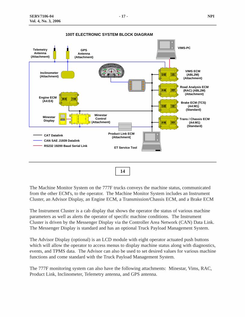
The Machine Monitor System on the 777F trucks conveys the machine status, communicatedfrom the other ECM's, to the operator. The Machine Monitor System includes an InstrumentCluster, an Advisor Display, an Engine ECM, a Transmission/Chassis ECM, and a Brake ECM
The Instrument Cluster is a cab display that shows the operator the status of various machineparameters as well as alerts the operator of specific machine conditions. The InstrumentCluster is driven by the Messenger Display via the Controller Area Network (CAN) Data Link.The Messenger Display is standard and has an optional Truck Payload Management System.
The Advisor Display (optional) is an LCD module with eight operator actuated push buttonswhich will allow the operator to access menus to display machine status along with diagnostics,events, and TPMS data. The Advisor can also be used to set desired values for various machinefunctions and come standard with the Truck Payload Management System.
The 777F monitoring system can also have the following attachments: Minestar, Vims, RAC,Product Link, Inclinometer, Telemetry antenna, and GPS antenna.
SERV7106-04 - 17 - NPIVol. 4, No. 3, 2006
TCS
0
510
15 2025
3035
X100
TelemetryAntenna
(Attachment)
GPSAntenna
(Attachment)
Inclinometer(Attachment)
Engine ECM(A4:E4)
MinestarDisplay
MinestarControl
(Attachment)
Product Link ECM(Attachment(
ET Service Tool
VIMS ECM(ABL2M)
(Attachment)
Road Analysis ECM(RAC) (ABL2M)(Attachment)
Brake ECM (TCS)(A4:M1)
(Standard)
Trans / Chassis ECM(A4:M1)
(Standard)
100T ELECTRONIC SYSTEM BLOCK DIAGRAM
VIMS-PC
CAT DatalinkCAN SAE J1939 DatalinkRS232 19200 Baud Serial Link

15
Shown is the Instrument Cluster (1) located in the center of the front dash panel. Eighteen dashindicators, five analog gauges, and the two digital displays are visible.
The five parameters monitored by the analog gauges are (bottom left to right):
- Brake oil temperature- Engine coolant temperature- Engine speed- Torque Converter oil temperature- Fuel Level
Alert indicators from left to right
- Left turn signal- Throttle lock- Primary steering loss- Secondary Steering engaged
SERV7106-04 - 18 - NPIVol. 4, No. 3, 2006
1

- Check engine- Park brake engaged- Brake system check- Power train system check- Action lamp- Charging system- Body up- Machine lockout active- Transmission in reverse- High beam- Retarder engaged- Traction control system engaged- Machine immobilizer- Right turn signal
SERV7106-04 - 19 - NPIVol. 4, No. 3, 2006

16
Shown above is the Caterpillar Advisor graphical display module. It is located on the right sideof the dash. It is the operator and Technician’s interface with the Caterpillar Monitoring andDisplay System. Information is displayed on a backlit LCD display screen.
The top portion of the screen is called the "Top Banner" and it displays vital machineinformation at all times. The Top Banner may display different information from machine tomachine, depending on the model and the attachments that are installed.
At the right of the display screen is a column of five User Interface buttons. These buttons areused to navigate through the numerous Advisor screens, to make menu selections, or to enterdata. The five buttons, from top to bottom, are:
- LEFT/UP Arrow Button (1) - This button is used for screen navigation or data entry. It can beused:
• to scroll up a vertical list or scroll left across a horizontal list;• to decrease a setting value, such as decreasing brightness/contrast.
SERV7106-04 - 20 - NPIVol. 4, No. 3, 2006
1
2
3
4
5

- DOWN/RIGHT Arrow Button (2)- This button is also used for screen navigation or dataentry. It can be used:
• to scroll down a vertical list or scroll right across a horizontal list;• to increase a setting value, such as increasing brightness/contrast.
- BACK Button (3) - This button is used:• to go up one level in a stair-step (hierarchical) menu structure, or to return to the
previous screen, much the same as the BACK Button is used in Windows InternetExplorer™;
• as a backspace, or cancel key when the operator or serviceman wishes to delete enteredcharacters.
- HOME Button (4)- This button is used to return to the home menu screen, regardless of whatscreen is currently displayed.
- OK Button (5) - This button is used:• to make selections from a screen;• to confirm an entry, such as a password, or for saving an operator profile entry.
Navigation through the menus and sub-menus is accomplished by using the ARROW Buttonsto highlight the desired selection, then pressing the OK Button. The ARROW Buttons are alsoused to highlight a mode or to set a parameter. Pressing the OK Button selects that option.(Example: Choosing either "Enabled" or "Disabled" for the FLOAT option in the ImplementSettings menu.)
NOTE: The column of five buttons at the left of the display screen currently have nofunction.
SERV7106-04 - 21 - NPIVol. 4, No. 3, 2006

17
Shown in the visual four switches and a power port.
- Port (1) is a 12 volt power supply.
- Rocker switch (2) will raise the engine idle if the throttle position sensor has failed.
- Rocker switch (3) controls the heated mirrors
- Switch (4) has been removed
- Switch (5) has been removed
SERV7106-04 - 22 - NPIVol. 4, No. 3, 2006
1 2 3 4 5

ENGINE
The top visual shows the right side of the new C32 engine used in the 777F trucks. The bottomvisual shows the left side of the new C32 engine. The 777F truck engines are designed to meetthe US Environmental Protection Agency (EPA) Tier II emissions regulations as well asEuropean Stage 2 regulations.
18
19
SERV7106-04 - 23 - NPIVol. 4, No. 3, 2006
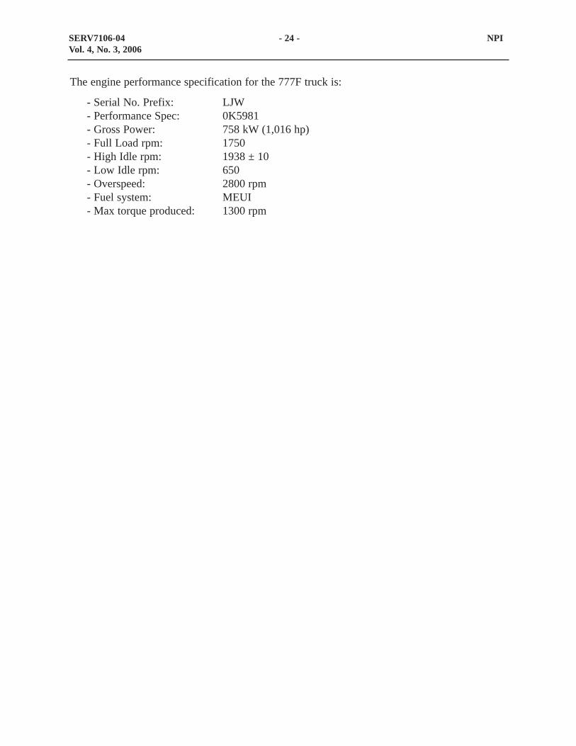
The engine performance specification for the 777F truck is:
- Serial No. Prefix: LJW- Performance Spec: 0K5981- Gross Power: 758 kW (1,016 hp)- Full Load rpm: 1750- High Idle rpm: 1938 ± 10- Low Idle rpm: 650- Overspeed: 2800 rpm- Fuel system: MEUI- Max torque produced: 1300 rpm
SERV7106-04 - 24 - NPIVol. 4, No. 3, 2006
20
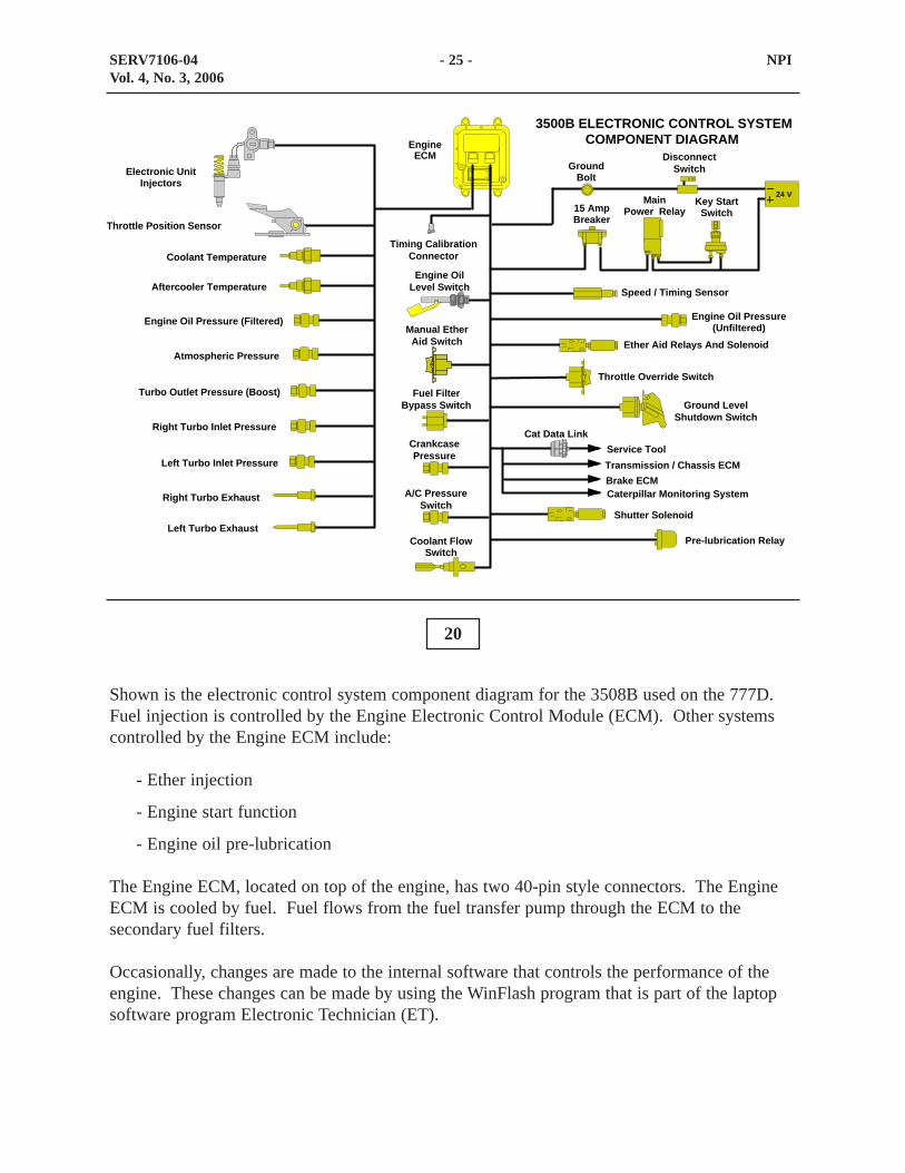
Shown is the electronic control system component diagram for the 3508B used on the 777D.Fuel injection is controlled by the Engine Electronic Control Module (ECM). Other systemscontrolled by the Engine ECM include:
- Ether injection
- Engine start function
- Engine oil pre-lubrication
The Engine ECM, located on top of the engine, has two 40-pin style connectors. The EngineECM is cooled by fuel. Fuel flows from the fuel transfer pump through the ECM to thesecondary fuel filters.
Occasionally, changes are made to the internal software that controls the performance of theengine. These changes can be made by using the WinFlash program that is part of the laptopsoftware program Electronic Technician (ET).
SERV7106-04 - 25 - NPIVol. 4, No. 3, 2006
A/C PressureSwitch
CrankcasePressure
Ground LevelShutdown Switch
Fuel FilterBypass Switch
Pre-lubrication Relay
Engine OilLevel Switch
Service ToolCat Data Link
Coolant Temperature
EngineECM
GroundBolt
15 AmpBreaker
MainPower Relay
Key StartSwitch
Speed / Timing Sensor
Engine Oil Pressure(Unfiltered)
Coolant FlowSwitch
Timing CalibrationConnector
Ether Aid Relays And Solenoid
DisconnectSwitch
3500B ELECTRONIC CONTROL SYSTEMCOMPONENT DIAGRAM
Electronic UnitInjectors
Turbo Outlet Pressure (Boost)
Right Turbo Inlet Pressure
Atmospheric Pressure
Engine Oil Pressure (Filtered)
Throttle Position Sensor
Shutter Solenoid
Aftercooler Temperature
Left Turbo Inlet Pressure
Right Turbo Exhaust
Left Turbo Exhaust
Throttle Override Switch
Manual EtherAid Switch
24 V
Transmission / Chassis ECMBrake ECMCaterpillar Monitoring System
21
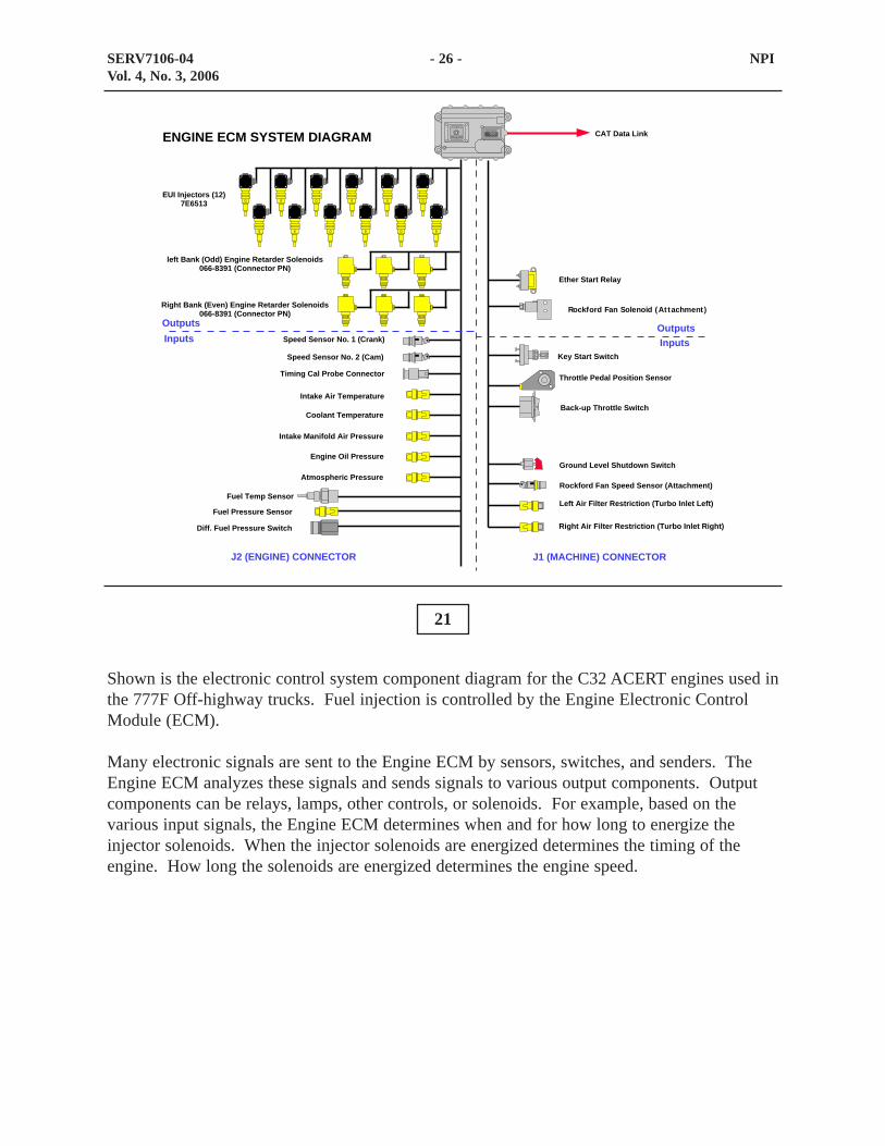
Shown is the electronic control system component diagram for the C32 ACERT engines used inthe 777F Off-highway trucks. Fuel injection is controlled by the Engine Electronic ControlModule (ECM).
Many electronic signals are sent to the Engine ECM by sensors, switches, and senders. TheEngine ECM analyzes these signals and sends signals to various output components. Outputcomponents can be relays, lamps, other controls, or solenoids. For example, based on thevarious input signals, the Engine ECM determines when and for how long to energize theinjector solenoids. When the injector solenoids are energized determines the timing of theengine. How long the solenoids are energized determines the engine speed.
SERV7106-04 - 26 - NPIVol. 4, No. 3, 2006
Ether Start Relay
Key Start Switch
Throttle Pedal Position Sensor
Back-up Throttle Switch
Ground Level Shutdown Switch
Rockford Fan Speed Sensor (Attachment)
Left Air Filter Restriction (Turbo Inlet Left)
Right Air Filter Restriction (Turbo Inlet Right)
EUI Injectors (12)7E6513
Right Bank (Even) Engine Retarder Solenoids066-8391 (Connector PN)
Speed Sensor No. 1 (Crank)
Speed Sensor No. 2 (Cam)
Timing Cal Probe Connector
Intake Air Temperature
Coolant Temperature
Intake Manifold Air Pressure
Engine Oil Pressure
Atmospheric Pressure
Fuel Temp Sensor
Fuel Pressure Sensor
Diff. Fuel Pressure Switch
J2 (ENGINE) CONNECTOR J1 (MACHINE) CONNECTOR
OutputsInputs
OutputsInputs
CAT Data LinkENGINE ECM SYSTEM DIAGRAM
left Bank (Odd) Engine Retarder Solenoids066-8391 (Connector PN)
Rockford Fan Solenoid (At tachment)
22
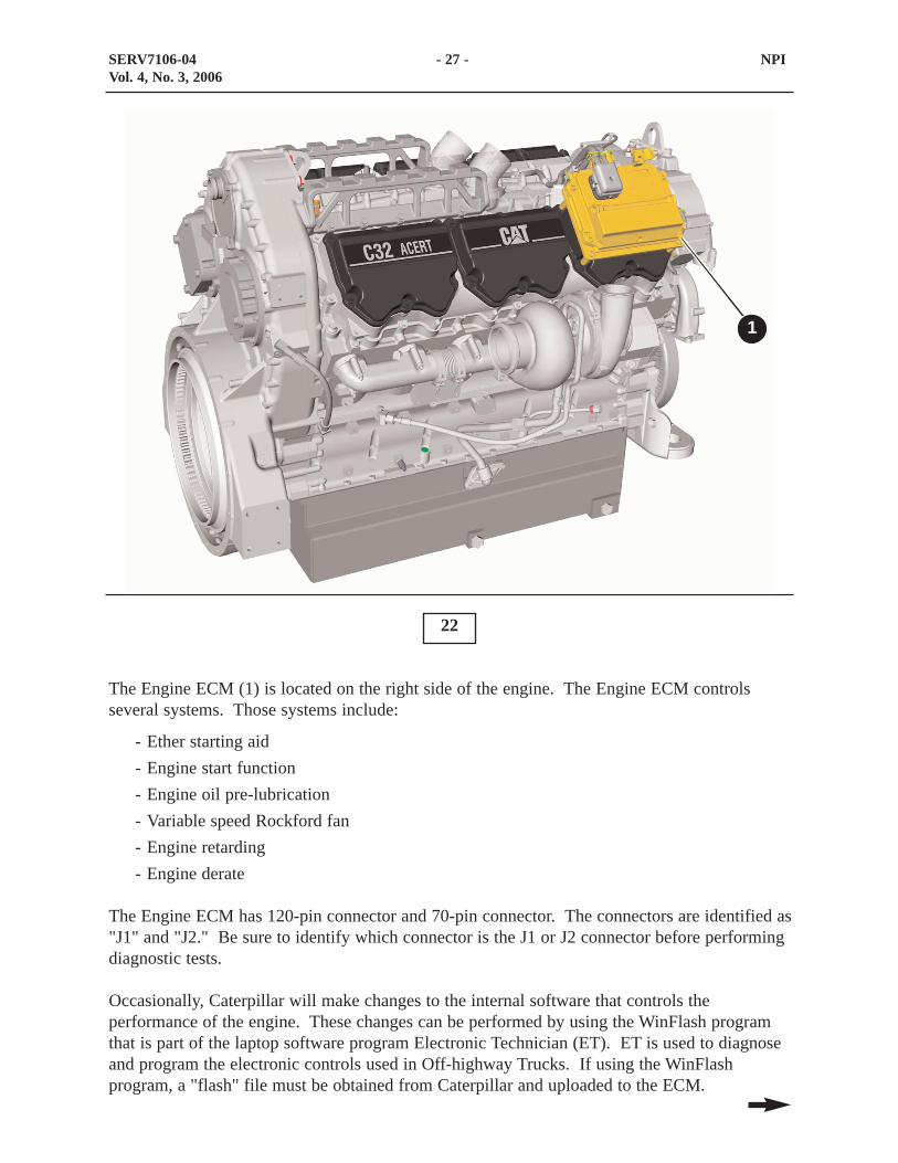
The Engine ECM (1) is located on the right side of the engine. The Engine ECM controlsseveral systems. Those systems include:
- Ether starting aid- Engine start function- Engine oil pre-lubrication- Variable speed Rockford fan- Engine retarding- Engine derate
The Engine ECM has 120-pin connector and 70-pin connector. The connectors are identified as"J1" and "J2." Be sure to identify which connector is the J1 or J2 connector before performingdiagnostic tests.
Occasionally, Caterpillar will make changes to the internal software that controls theperformance of the engine. These changes can be performed by using the WinFlash programthat is part of the laptop software program Electronic Technician (ET). ET is used to diagnoseand program the electronic controls used in Off-highway Trucks. If using the WinFlashprogram, a "flash" file must be obtained from Caterpillar and uploaded to the ECM.
SERV7106-04 - 27 - NPIVol. 4, No. 3, 2006
1
A 2-pin timing calibration connector is located next to the Engine ECM. If the engine requirestiming calibration, a timing sensor (magnetic pickup) is installed in the flywheel housing andconnected to the timing calibration connector.
Using the Caterpillar ET service tool, the timing calibration is performed automatically. Thisstep is performed to avoid instability and ensures that no backlash is present in the timing gearsduring the calibration process.
Timing calibration improves fuel injection accuracy by correcting for any slight tolerancesbetween the crankshaft, timing gears, and timing wheel.
Timing calibration is normally performed after the following procedures:
- ECM replacement
- Cam or crank sensor replacement
- Timing wheel replacement
SERV7106-04 - 28 - NPIVol. 4, No. 3, 2006

23
Intake air temperature sensor (1) and (4) are located on top of the engine. Sensor (1) is locatedtoward the left rear and sensor (4) is located toward the front right side. The intake airtemperature sensor is an analog sensor that is monitored by the engine ECM. The ECMmonitors intake air temperature for derating the engine at high temperatures, for engineshutdown at high temperatures, and for signaling the monitoring system in the event of aproblem.
The turbo outlet pressure sensors (2) and (5) are used for calculating boost.
The coolant temperature sensor (3) is located on top of the engine toward the front left side.The coolant temperature sensor is an analog sensor that is monitored by the engine ECM.When the coolant temperature get to high, the engine ECM will signal the monitoring system todisplay a warning.
The atmospheric pressure sensor (6) is located on top of the engine toward the front right side.The atmospheric pressure sensor is a digital sensor that is monitored by the engine ECM. TheECM monitors atmospheric pressure for the following: altitude derate, air inlet restrictionderate, and calibration reference for other sensors.
SERV7106-04 - 29 - NPIVol. 4, No. 3, 2006
1 2 3
4 5 6

24
The cam speed/timing sensor (1) is located on the right side of the engine in the back side ofthe timing gear housing behind the primary fuel filter. This sensor is used as a backup for thecrank speed/timing sensor. If the crank speed/timing sensor fails, the cam speed/timing sensorallows for continuous operation.
SERV7106-04 - 30 - NPIVol. 4, No. 3, 2006
1

25
The crankshaft speed/timing sensor (1) is located on the lower left of the engine toward thefront side. This sensor measures engine speed and timing for control of the timing and deliveryof fuel to each of the engine's cylinders. Sensing engine speed allows engine speed governing,fuel limiting, and fuel injection timing. If the crank speed/timing sensor fails, the camspeed/timing sensor allows for continuous operation.
The oil pressure sensor (2) is located on the left side of the engine. The oil pressure sensor isan analog sensor that is monitored by the Engine ECM. When the oil pressure drops to low, theengine ECM will signal the monitoring system to display a warning. The ECM will also log anevent that requires a factory password to clear.
The switch (3) monitors the oil level in the pan.
SERV7106-04 - 31 - NPIVol. 4, No. 3, 2006
1 2
3
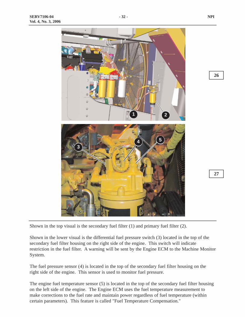
Shown in the top visual is the secondary fuel filter (1) and primary fuel filter (2).
Shown in the lower visual is the differential fuel pressure switch (3) located in the top of thesecondary fuel filter housing on the right side of the engine. This switch will indicaterestriction in the fuel filter. A warning will be sent by the Engine ECM to the Machine MonitorSystem.
The fuel pressure sensor (4) is located in the top of the secondary fuel filter housing on theright side of the engine. This sensor is used to monitor fuel pressure.
The engine fuel temperature sensor (5) is located in the top of the secondary fuel filter housingon the left side of the engine. The Engine ECM uses the fuel temperature measurement tomake corrections to the fuel rate and maintain power regardless of fuel temperature (withincertain parameters). This feature is called "Fuel Temperature Compensation."
26
27
SERV7106-04 - 32 - NPIVol. 4, No. 3, 2006
1
53
4
2

28
The throttle position sensor (1) provides the desired throttle position to the Engine ECM. Thethrottle position sensor is located behind the throttle pedal in the cab.
SERV7106-04 - 33 - NPIVol. 4, No. 3, 2006
1

29
Shown is the pre-lube pump (1) for the 777F trucks. The pre-lube pump is located on the frontof the crossmember that supports the front struts. The pump is used for both engine pre-lubeand Quick EVAC.
SERV7106-04 - 34 - NPIVol. 4, No. 3, 2006
1
30
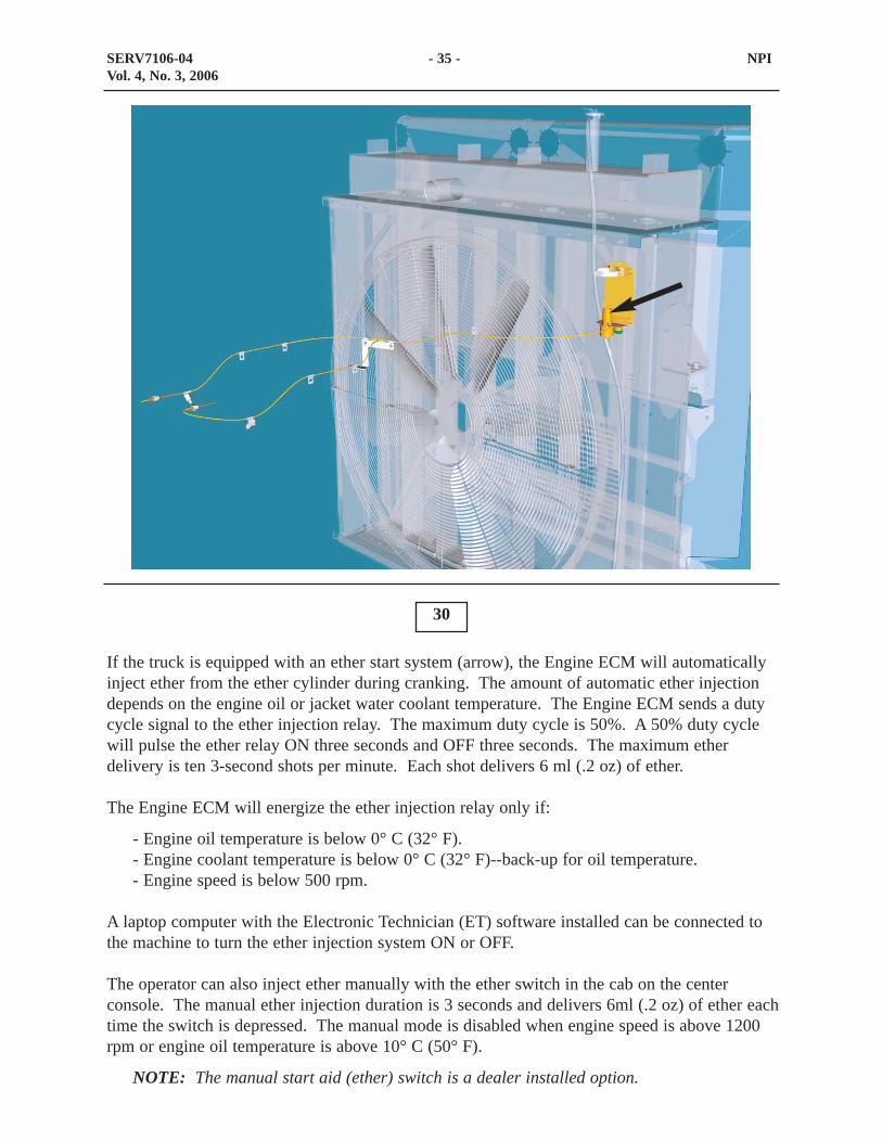
If the truck is equipped with an ether start system (arrow), the Engine ECM will automaticallyinject ether from the ether cylinder during cranking. The amount of automatic ether injectiondepends on the engine oil or jacket water coolant temperature. The Engine ECM sends a dutycycle signal to the ether injection relay. The maximum duty cycle is 50%. A 50% duty cyclewill pulse the ether relay ON three seconds and OFF three seconds. The maximum etherdelivery is ten 3-second shots per minute. Each shot delivers 6 ml (.2 oz) of ether.
The Engine ECM will energize the ether injection relay only if:
- Engine oil temperature is below 0° C (32° F).- Engine coolant temperature is below 0° C (32° F)--back-up for oil temperature.- Engine speed is below 500 rpm.
A laptop computer with the Electronic Technician (ET) software installed can be connected tothe machine to turn the ether injection system ON or OFF.
The operator can also inject ether manually with the ether switch in the cab on the centerconsole. The manual ether injection duration is 3 seconds and delivers 6ml (.2 oz) of ether eachtime the switch is depressed. The manual mode is disabled when engine speed is above 1200rpm or engine oil temperature is above 10° C (50° F).
NOTE: The manual start aid (ether) switch is a dealer installed option.
SERV7106-04 - 35 - NPIVol. 4, No. 3, 2006

Cooling System
Shown in the top visual is the cooling system for the 777F. The cooling systems for the 777Fand 777D are similar. The flow of coolant through the system is the same, however thecomponents are located in different locations due to a new engine on the 777F.
Shown in the lower visual is the flow of coolant through the cooling system for the 777F.These trucks use a conventional radiator core. Coolant flows from the pump through thecoolers and into the engine block. Coolant flows through the engine block and the cylinderheads. From the cylinder heads, the coolant returns to the temperature regulators and eithergoes directly to the water pump through the bypass tubes or to the radiator.
31
32
SERV7106-04 - 36 - NPIVol. 4, No. 3, 2006
ThermostatHousing
Radiator
Water Pump
Engine Oil Cooler
Hoist and BrakeOil Cooler
Transmission andTorque Converter
Oil Cooler
Engine Block
ATAAC
COOLING SYSTEM FLOW

Shown in the top visual is the cooling package of the 777D. The cooling package is dividedinto two systems. The two systems are the jacket water cooling system (2) and the aftercoolersystem (1).
Shown in the bottom visual is the Next Generation Modular Radiator (NGMR) (3) for the 777Ftrucks.
Also shown is the ATAAC (4) which is mounted in front of the radiator. Intake air is cooledafter being compressed by the turbocharger before being routed to the engine combustionchamber.
33
34
SERV7106-04 - 37 - NPIVol. 4, No. 3, 2006
21
3
4
4

35
POWER TRAIN HYDRAULIC SYSTEM
Shown is the transmission and torque converter hydraulic system for the 777F. A five sectionpump is located at the rear of the torque converter housing. One section scavenges oil from thebottom of the torque converter case and returns the oil to the hydraulic tank. The secondsection pumps charge oil to the torque converter. The third section provides pilot oil to thefollowing circuits:
- Lockup valve- Variable speed fan clutch control- Hoist pilot signal resolver- Traction control
The fourth section scavenges oil from the transmission sump and pumps it to the followinglocations:
- Transmission filters- Transmission oil cooler
The fifth section supply charging oil to the transmission control valves.
SERV7106-04 - 38 - NPIVol. 4, No. 3, 2006
ToBrake
Cooling
HydraulicControls
Transmission
TorqueConverter
LockupValve
ToVariableSpeedClutchControl
ToHoist Pilot
SignalResolver
ToTractionControl
Pilot
POWER TRAIN HYDRAULIC SYSTEM

Power Train Components
Shown in the top visual is the new five section gear pump. The gear pump is a different designthen the previous 777D. The gear pumps are for the following circuits:
-Torque converter scavenge (1)-Torque converter charge (2)-Lockup clutch valve pilot circuit (3)-Transmission scavenge (4)-Transmission charge (5)
36
37
SERV7106-04 - 39 - NPIVol. 4, No. 3, 2006
5
4 3 2
1
6
7
8

Shown in the lower visual are some of the torque converter system components for the 777F.The torque converter systems are similar between the 777D and 777F. The torque converterinlet relief valve (6) and the outlet relief valve (7) will function the same. The lockup clutchvalve (8) on the 777F is now an ECPC valve.
SERV7106-04 - 40 - NPIVol. 4, No. 3, 2006

Shown in the top visual is the 777D torque converter charging filter (1). The charging filter islocated on the left frame rail, behind the left front tire.
Shown in the bottom visual is the 777F torque converter charging filter (2). The charging filteris located on the right frame rail, behind the right front tire.
38
39
SERV7106-04 - 41 - NPIVol. 4, No. 3, 2006
1
2

Shown in the top visual is the park brake release filter for the 777D. Oil flows from theparking brake release filter to the parking brake release valve. Oil then flows from the parkingbrake release valve to the lockup clutch valve. The park brake release filter is located in frontof the hydraulic tank on the left side of the frame.
Shown in the bottom visual is the lockup clutch valve filter for the 777F. Filtered pump oilflows directly to the ECPC type lockup clutch valve. The filter is located inside of the leftframe rail. The filter has a bypass switch. The bypass switch provides an input signal to theCaterpillar Monitoring System, which informs the operator if the filter is restricted. The filterhousing has an S.O.S tap and a pressure tap.
40
41
SERV7106-04 - 42 - NPIVol. 4, No. 3, 2006

Shown in the top visual is the 777D ICM controlled transmission. A cover has to be removedin order to check the pressure on this ICM system.
Shown in the bottom visual is the 777F ECPC transmission. This new transmission haspressure taps located on the outside of the transmission. This feature will aid in preventingcontamination from entering the transmission as well as saving time when checking thepressures on the 777F transmission.
SERV7106-04 - 43 - NPIVol. 4, No. 3, 2006
43
42

Shown in the top visual is the 777D transmission charge filter. The 777D has a single filterlocated on the outside of the frame behind the right front tire.
Shown in the bottom visual is the 777F transmission charge filters. The 777F has two filtersmounted on the cross member on the right side of the machine. The rear filter housing has anS•O•S tap and a pressure tap. The rear filter housing also has a bypass switch. The bypassswitch provides an input signal to the Caterpillar Monitoring System, which informs theoperator if the filter is restricted.
44
45
SERV7106-04 - 44 - NPIVol. 4, No. 3, 2006

Shown in the top visual is S•O•S port (1) located on the torque converter filter. Port (1) drawsa sample from the outlet of the filter.
Shown in the lower visual is the torque converter lockup clutch filter. Port (2) is an S•O•Sport. Port (3) is a pressure tap. The pressure indicated at tap (3) is pump pressure for thelockup clutch pilot circuit.
46
47
SERV7106-04 - 45 - NPIVol. 4, No. 3, 2006
23
1
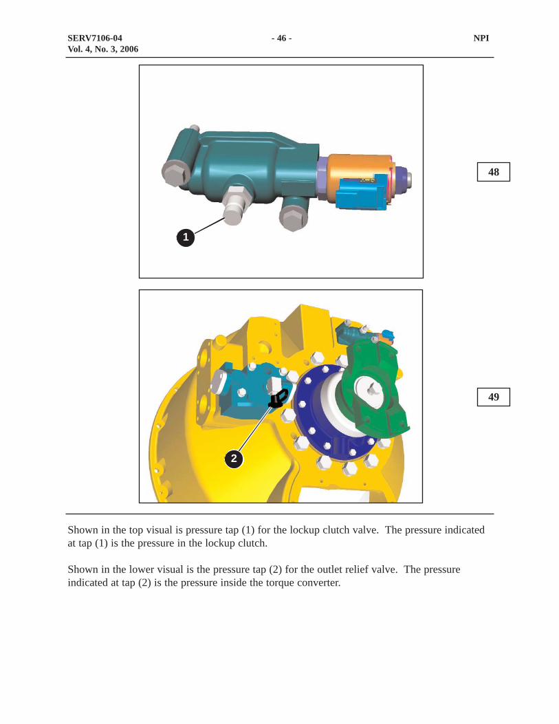
Shown in the top visual is pressure tap (1) for the lockup clutch valve. The pressure indicatedat tap (1) is the pressure in the lockup clutch.
Shown in the lower visual is the pressure tap (2) for the outlet relief valve. The pressureindicated at tap (2) is the pressure inside the torque converter.
48
49
SERV7106-04 - 46 - NPIVol. 4, No. 3, 2006
1
2
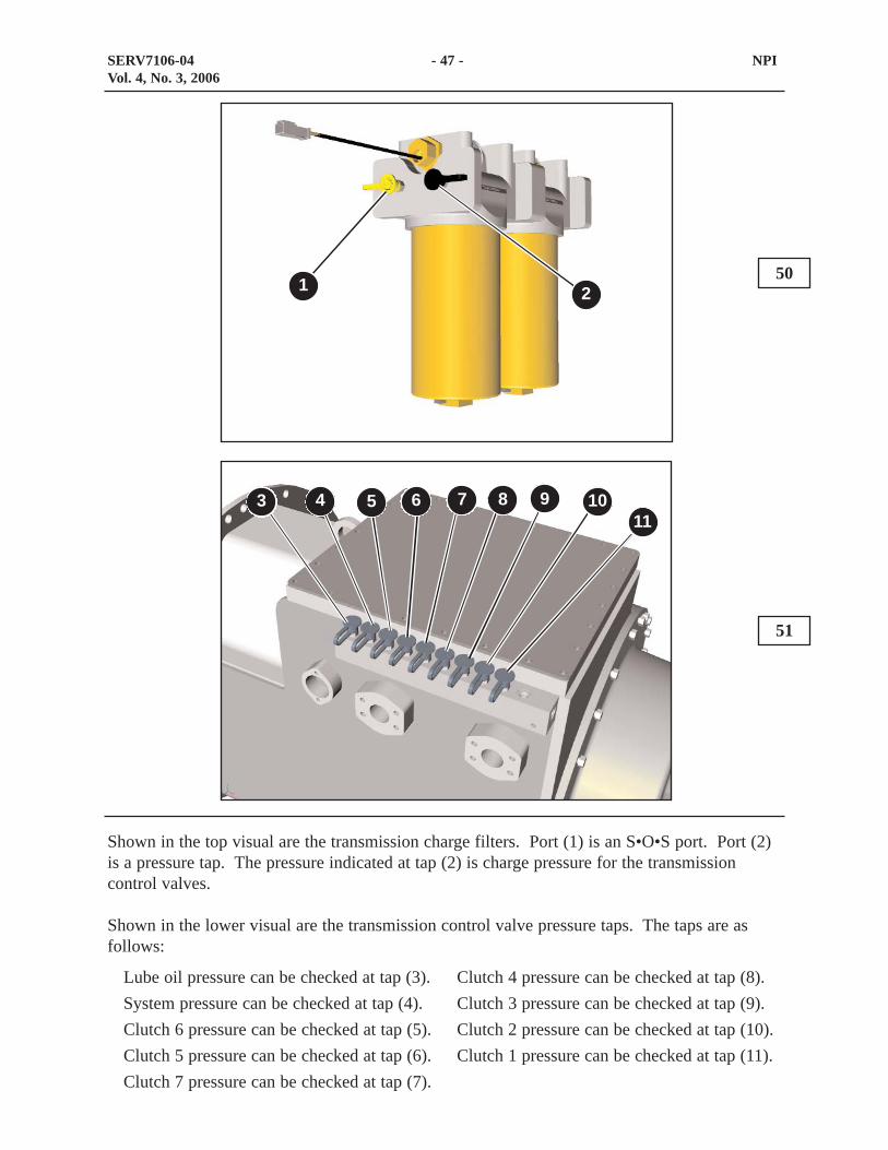
Shown in the top visual are the transmission charge filters. Port (1) is an S•O•S port. Port (2)is a pressure tap. The pressure indicated at tap (2) is charge pressure for the transmissioncontrol valves.
Shown in the lower visual are the transmission control valve pressure taps. The taps are asfollows:
50
51
SERV7106-04 - 47 - NPIVol. 4, No. 3, 2006
1 2
3 4 5 6 7 8 9 1011
Clutch 4 pressure can be checked at tap (8). Clutch 3 pressure can be checked at tap (9).Clutch 2 pressure can be checked at tap (10).Clutch 1 pressure can be checked at tap (11).
Lube oil pressure can be checked at tap (3). System pressure can be checked at tap (4). Clutch 6 pressure can be checked at tap (5).Clutch 5 pressure can be checked at tap (6).Clutch 7 pressure can be checked at tap (7).

52
Power Train Electronic Control System
Shown in this visual are the inputs and outputs for the 777F trucks.
The purpose of the Transmission/Chassis ECM is to determine the desired transmission gearand energize solenoids to shift the transmission up or down as required based on informationfrom both the operator and machine. This Transmission/Chassis ECM also controls all the hoistfunctions.
The Transmission/Chassis ECM receives information from various input components such asthe shift lever switch, Transmission Output Speed (TOS) sensors, and the transmission gearswitch.
Based on the input information, the Transmission/Chassis ECM determines whether thetransmission should upshift, downshift, engage the lockup clutch, or limit the transmission gear.These actions are accomplished by sending signals to various output components.
SERV7106-04 - 48 - NPIVol. 4, No. 3, 2006
OUTPUTSINPUTS
Start Relay
TransmissionSolenoid 1-7
Steering SystemDisable Solenoid
Parking BrakeProportional Solenoid
Lockup ClutchSolenoid
Hoist Raise Solenoid
Hoist Lower Solenoid
Secondary Steering /QuickEvac /
Prelube Relay
Starter Lockout Lamp
Back-up Alarm Relay
Torque Converter OilTemperature Sensor
Primary SteeringPressure Switch
Secondary SteeringMotor State
R-Terminal
Secondary Steering SystemSteering Switch
TransmissionCharge Filter
Bypass Switch
Transmission OutputSpeed Sensor 1
Key Start Switch
Machine Lockout Switch
Starter Lockout Switch
Engine Oil Evacuation Enable
Engine Oil Evacuation
Secondary Steer Test Switch
Drive Gear Select Switches
Shift Lever
Fuel Level Sender
Engine Speed Sensor
Hoist Lever
Secondary BrakePressure Switch
Manual Retarder
Inclinometer
Transmission OutputSpeed Sensor 2
Transmission OilLevel Switch
Location Codes
Machine Lockout Lamp
Cat Data Link
TRANSMISSION / CHASSIS CONTROL MODULE SYSTEM DIAGRAM
Transmission InputSpeed Sensor
Secondary Brake Posit ion Sensor

Output components include the upshift, downshift, and lockup solenoids; the back-up alarm,and others.
The Engine ECM, the Machine Monitor System, and the Transmission/Chassis ECM allcommunicate with each other through the CAT Data Link. Communication between theelectronic controls allows the sensors of each system to be shared. Many additional benefitsare provided, such as Controlled Throttle Shifting (CTS). CTS occurs when theTransmission/Chassis ECM tells the Engine ECM to reduce or increase engine fuel during ashift to lower stress to the power train.
The Transmission/Chassis ECM is also used to control the hoist system. The hoist lever sensorsends duty cycle input signals to the Transmission/Chassis ECM. Depending on the position ofthe sensor and the corresponding duty cycle, the Transmission/Chassis ECM will signal theTransmission/Chassis ECM. The Transmission/Chassis ECM will energize one of the solenoidslocated on the hoist valve..
The Electronic Technician (ET) Service Tool can be used to perform several diagnostic andprogramming functions.
SERV7106-04 - 49 - NPIVol. 4, No. 3, 2006

53
STEERING SYSTEM
This schematic shows the steering hydraulic system for the 777F trucks. The steering systemon the 777F is similar to the 777D with a few exceptions:
- Adding the steering disable solenoid valve- Location of components has changed
When energized, the steering disable solenoid valve stops the oil flow coming from steeringpump. This prevents the front wheels from turning to allow servicing to be conducted safely inthe front wheel area.
The steering system uses a load sensing, pressure compensated pump. Minimal horsepower isused by the steering system when the truck is traveling in a straight path. Steering hydraulichorsepower requirements depend on the amount of steering pressure and flow required by thesteering cylinders.
Steering oil flows from the pump to the steering disable solenoid valve. Oil then flows fromthe steering disable valve to the steering valve located on the frame behind the right frontsuspension cylinder. The flow of oil continues from the steering valve to the HMU whichmeters flow to the steering cylinders. The faster the HMU is turned, the higher the flow sent tothe steering cylinders, and the faster the wheels will change direction.
SERV7106-04 - 50 - NPIVol. 4, No. 3, 2006
LoadSensingResolver
LoadSensing
Valve
SecondarySteering
Primary ReliefValve
SecondarySteering
Pump
SecondarySteering
Back-up ReliefValve
M
Piston Pump andLoad Sensing
Controller
SteeringFilter
SteeringPressureSwitch
CrossoverRelief Valves
HMU
PressureReducing
Valve
SteeringValve
Case DrainFilter
Primary SteeringBack-up Relief Valve
TransmissionChassis
ECM
STEERING HYDRAULICSYSTEM
SecondaryPressureSwitch
SteeringDisableValve

Shown in the top visual is the 777D steering system tank. The tank is located on the rightplatform.
Shown in the lower visual is the 777F steering system tank. The tank is located on the rightplatform. The 777F steering tank functions the same as the the 777D steering tank.
54
55
SERV7106-04 - 51 - NPIVol. 4, No. 3, 2006
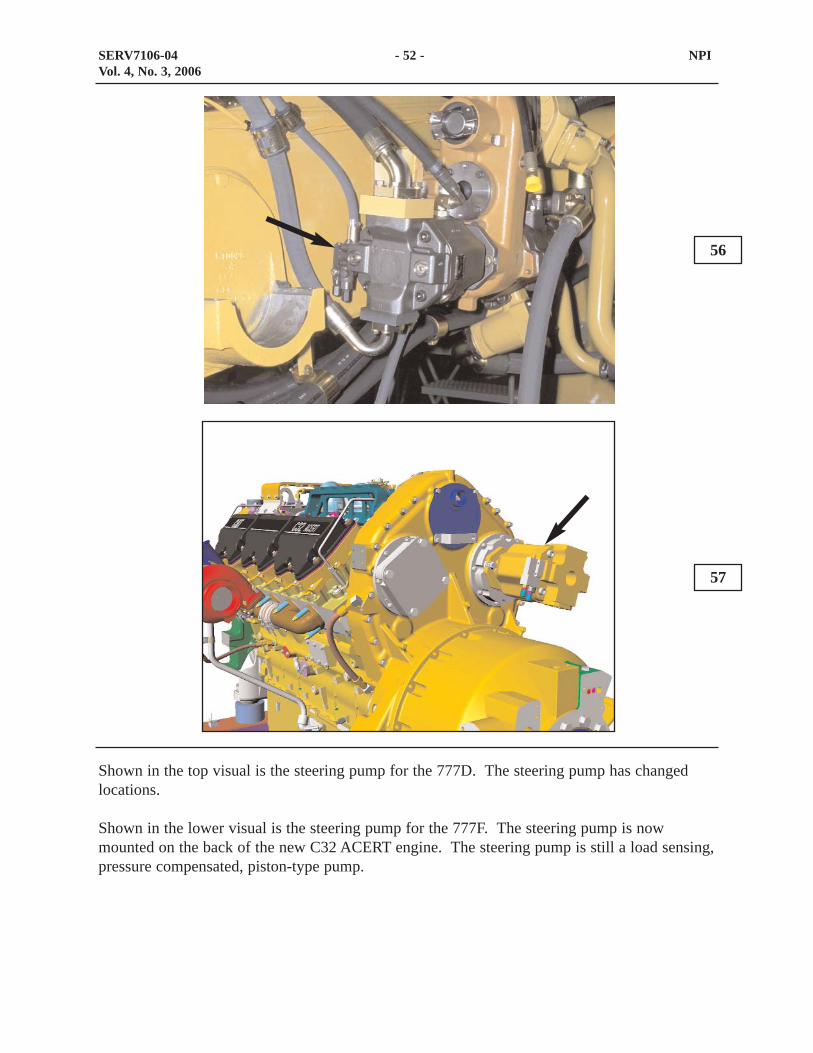
Shown in the top visual is the steering pump for the 777D. The steering pump has changedlocations.
Shown in the lower visual is the steering pump for the 777F. The steering pump is nowmounted on the back of the new C32 ACERT engine. The steering pump is still a load sensing,pressure compensated, piston-type pump.
56
57
SERV7106-04 - 52 - NPIVol. 4, No. 3, 2006

The steering disable valve (1) is located behind the shock on the right frame rail.
When the steering disable solenoid valve (2) is energized, the flow from the steering to thesteering valve is blocked by the steering disable valve (1). This allows servicing behind thefront wheels with the machine running.
When the machine lockout switch, located under a panel on the left stair way, is toggled asignal is sent to the Transmission/Chassis ECM. The Transmission/Chassis ECM energizes thesteering disable solenoid. Now the machine can be serviced behind the front wheels safely.
58
59
SERV7106-04 - 53 - NPIVol. 4, No. 3, 2006
1
2

Shown in the top visual is the steering valve (1) for the 777D.
Shown in the lower visual is the steering valve (3) for the 777F. The 777F uses the samesteering valve as the 777D. The steering valve is located in the same place however thesteering valve is mounted differently. The pressure tap (3) checks the pressure in the supplyline to the HMU. If the supply oil pressure to the HMU is below specification, the relief valve(2) many need to be adjusted.
60
61
SERV7106-04 - 54 - NPIVol. 4, No. 3, 2006
1
2
3 4

Shown in the top visual is the HMU (1) for the 777D.
Shown in the lower visual is the HMU (2) for the 777F. The HMU will function the same andis in the same general location. The HMU for the 777F will be easier to service due to theredesigned walkways.
62
63
SERV7106-04 - 55 - NPIVol. 4, No. 3, 2006
1
2

Shown in the top visual is the electric secondary steering pump (1) on the 777D.
Shown in the lower visual is the electric secondary steering pump (3) on the 777F. The pumpand motor are the same as the 777D however the location has changed. The pump and motorare now located on the front crossmember. The secondary pressure switch (2) is also mountednext to the secondary steering pump. The pressure switch (2) detects if the wheels are beingturned via the steering wheel when secondary steering is applied. When the wheel is turned ina secondary steering condition, the pressure switch (2) will signal the Transmission/ChassisECM and the QuickEvac function will be disabled.
64
65
SERV7106-04 - 56 - NPIVol. 4, No. 3, 2006
1
2
3
66
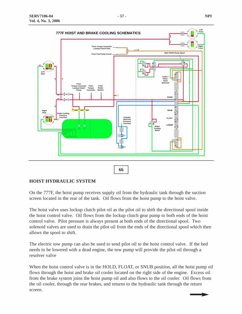
HOIST HYDRAULIC SYSTEM
On the 777F, the hoist pump receives supply oil from the hydraulic tank through the suctionscreen located in the rear of the tank. Oil flows from the hoist pump to the hoist valve.
The hoist valve uses lockup clutch pilot oil as the pilot oil to shift the directional spool insidethe hoist control valve. Oil flows from the lockup clutch gear pump to both ends of the hoistcontrol valve. Pilot pressure is always present at both ends of the directional spool. Twosolenoid valves are used to drain the pilot oil from the ends of the directional spool which thenallows the spool to shift.
The electric tow pump can also be used to send pilot oil to the hoist control valve. If the bedneeds to be lowered with a dead engine, the tow pump will provide the pilot oil through aresolver valve
When the hoist control valve is in the HOLD, FLOAT, or SNUB position, all the hoist pump oilflows through the hoist and brake oil cooler located on the right side of the engine. Excess oilfrom the brake system joins the hoist pump oil and also flows to the oil cooler. Oil flows fromthe oil cooler, through the rear brakes, and returns to the hydraulic tank through the returnscreen.
SERV7106-04 - 57 - NPIVol. 4, No. 3, 2006
From Torque ConverterLockup Clutch Pilot
From Tow Pump Circuit
LeftFront
RightFront
Main Relief Dump Spool
Lower /Float /Snub
Solenoid
RAISE
SNUB
FLOAT
LOWERBrake
CoolingRelief
CylinderRod EndPressureTest Port
RightRear Brake Cooling
PressureTest Port
FromTorque Converter
Lockup ClutchPump
FromTorque
Converter
FromBrake
System
LeftRear
777F HOIST AND BRAKE COOLING SCHEMATICS

An oil cooler relief valve is located in the hoist control valve. The relief valve limits the brakeoil cooling pressure when the hoist control valve is in the HOLD, FLOAT, or SNUB position.
The main difference between the previous truck and the 777F is the elimination of the brakerelease valve from the hoist hydraulic system. The hoist valve now receives pilot oil from thelockup clutch supply oil circuit. The brake release function is handled by the brake system onthe 777F trucks and will be discussed later in this document.
SERV7106-04 - 58 - NPIVol. 4, No. 3, 2006

67
Shown in the visual is the new location of the hoist pump (1). The hoist pump is a gear typepump and is attached to the brake cooling pump (2) and the brake charging pump (3). Thehoist pump is now driven by the gears at the back of the engine.
SERV7106-04 - 59 - NPIVol. 4, No. 3, 2006
1 2 3

68
Shown in the visual is the new location of the hoist control valve (1). The valve (1) is locatedbehind the engine on the right side of the frame. The valve (1) will function the same as thehoist control valve on the 777D.
SERV7106-04 - 60 - NPIVol. 4, No. 3, 2006
1

The top visual shows the hoist control lever for the 777D (1) trucks. The lower visual showsthe hoist control lever for the 777F (2). The function of these levers are the same.
The operator controls the hoist lever. The four positions of the hoist lever are RAISE, HOLD,FLOAT, and LOWER. The hoist lever controls a Pulse Width Modulated (PWM) positionsensor mounted to the lower end of the hoist lever. The PWM sensor sends duty cycle inputsignals to the Transmission/Chassis ECM. Depending on the position of the sensor and thecorresponding duty cycle, one of the two solenoids located on the hoist valve is energized.
69
70
SERV7106-04 - 61 - NPIVol. 4, No. 3, 2006
1
2
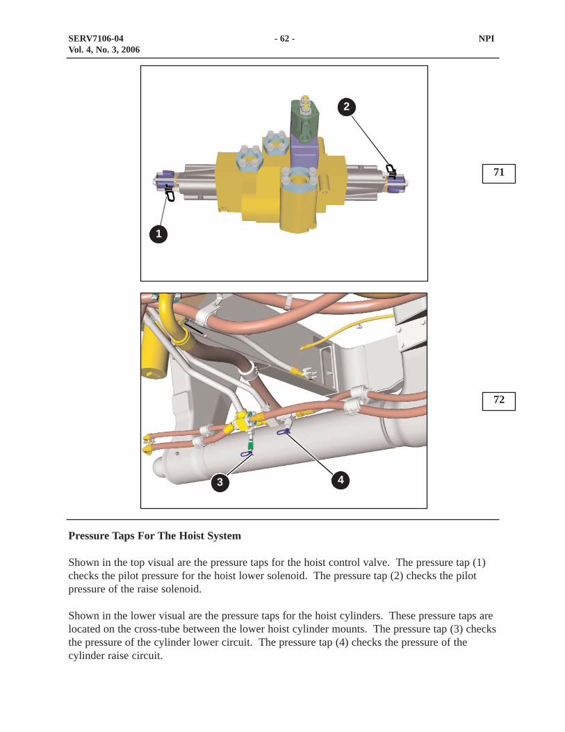
Pressure Taps For The Hoist System
Shown in the top visual are the pressure taps for the hoist control valve. The pressure tap (1)checks the pilot pressure for the hoist lower solenoid. The pressure tap (2) checks the pilotpressure of the raise solenoid.
Shown in the lower visual are the pressure taps for the hoist cylinders. These pressure taps arelocated on the cross-tube between the lower hoist cylinder mounts. The pressure tap (3) checksthe pressure of the cylinder lower circuit. The pressure tap (4) checks the pressure of thecylinder raise circuit.
71
72
SERV7106-04 - 62 - NPIVol. 4, No. 3, 2006
1
2
3 4
73
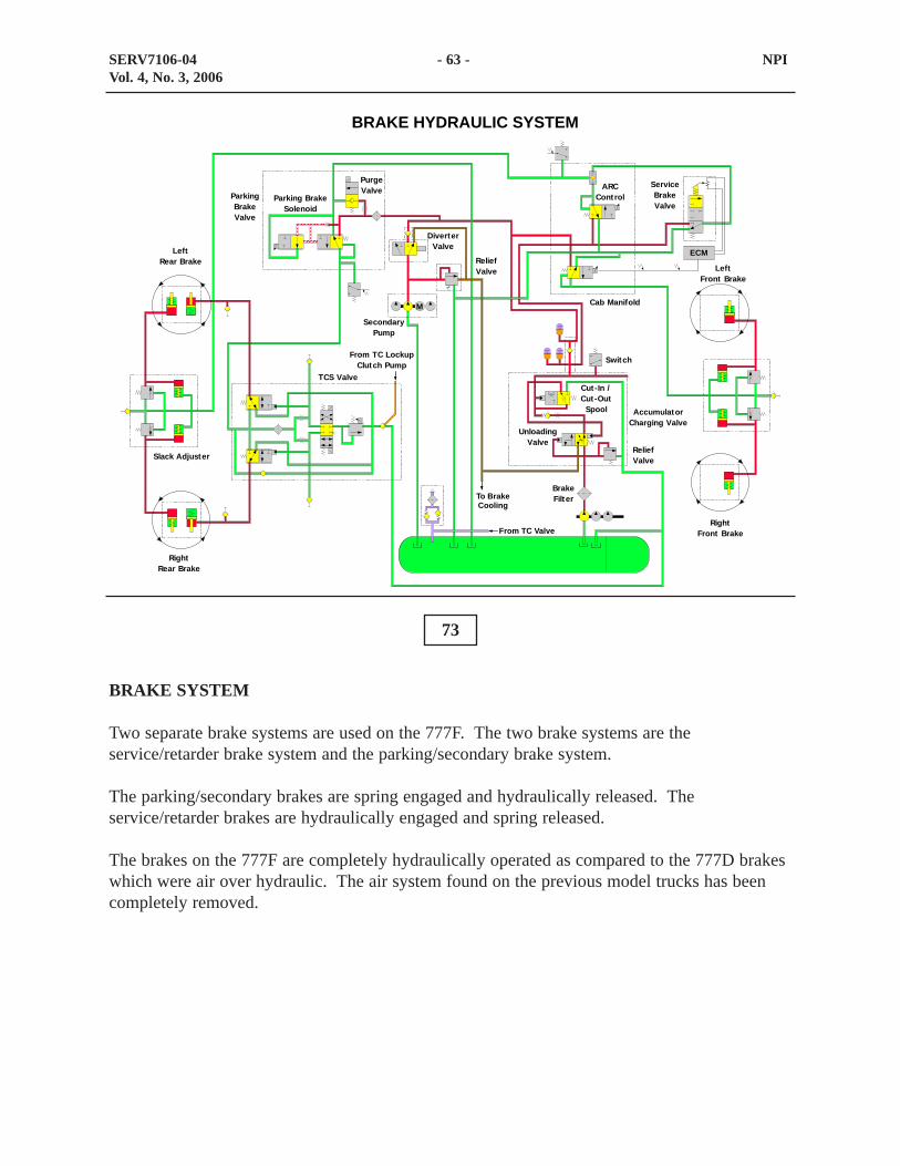
BRAKE SYSTEM
Two separate brake systems are used on the 777F. The two brake systems are theservice/retarder brake system and the parking/secondary brake system.
The parking/secondary brakes are spring engaged and hydraulically released. Theservice/retarder brakes are hydraulically engaged and spring released.
The brakes on the 777F are completely hydraulically operated as compared to the 777D brakeswhich were air over hydraulic. The air system found on the previous model trucks has beencompletely removed.
SERV7106-04 - 63 - NPIVol. 4, No. 3, 2006
To BrakeCooling
BRAKE HYDRAULIC SYSTEM
UnloadingValve
Cut-In /Cut -Out
Spool
ReliefValve
ARCControl
ServiceBrakeValve
Cab Manifold
AccumulatorCharging Valve
Slack Adjuster
SecondaryPump
DiverterValve
ReliefValve
PurgeValve
ParkingBrakeValve
Parking BrakeSolenoid
TCS Valve
Switch
LeftRear Brake
RightRear Brake
M
ECM
LeftFront Brake
RightFront BrakeFrom TC Valve
From TC LockupClutch Pump
BrakeFilter

74
Shown is the hydraulic brake system for the 777F trucks.
This block diagram shows the major components of the brake system. The brakes are hydraulicunlike the previous machines which had an air over oil system. The front and rear brakes areoil cooled internal wet disc type brakes. The 777F can also be ordered with an optional calipertype front brake system.
Oil is drawn from the hydraulic tank by the brake section of the combination implement/brakepump. Oil flows through the brake filter to the accumulator charging valve. The accumulatorcharging valve directs supply oil to the other components. The accumulator charging valve alsocontrols the CUT-IN and CUT-OUT pressure. When the accumulators are charged, thecharging valve will direct access pump flow to brake cooling.
After leaving the service brake accumulator, oil flows through the ARC (Automatic RetarderControl) manifold to the service brake control valve. The service brake control valve directspump flow to the rear service brakes to stop the truck.
SERV7106-04 - 64 - NPIVol. 4, No. 3, 2006
Pump
Tank
CheckValve
BrakeControlValve
Diverter Relief
SlackAdjuster
SecondaryPump
To BrakeCooling
To Brake Cooling
AccumulatorCharging Valve
Rear Brake
Rear Brake
ParkBrakeValve
TCS Valve
ARCManifold
Front Brake
Switch
BRAKE SYSTEM
SlackAdjuster
Front Brake
BrakeFilter
BrakeAccumulators

The front brakes are only engaged when the brake ECM energizes the front brake ARCsolenoid. The front brakes receive supply oil from the parking brake accumulator.
After leaving the parking brake accumulator, oil flows to the parking brake valve, the towingdiverter valve, and the ARC solenoid. When the parking brake is activated, the supply oil forreleasing the parking brake is diverted to tank. When the parking brake solenoid is energized(parking brake released), the parking brake valve sends oil through the Traction Control System(TCS) valve which then releases the parking brakes. The parking brakes are spring applied andpressure released.
The diverter valve, under normal operation, should be closed and allows no oil to flow past. Ifthe truck is to be towed with a dead engine, the diverter valve must be shifted manually. Whenmanually shifted, the diverter valve diverts oil flow from the electric brake retract pump to theparking brake valve and the ARC solenoid for the front brakes.
SERV7106-04 - 65 - NPIVol. 4, No. 3, 2006

Shown in the top visual is the parking brake release pump (2) and the brake oil cooling pump (1) for the 777D. With the removal of the air over hydraulic brake system, the brakepumps are no longer mounted in this location.
Shown in the lower visual is the new location of the brake charging pump (4) and the brake oilcooling pump (3). This set of pumps is mounted on the left rear side of the engine. The 777Fbrake system is charged by the gear pump (4) which supplies oil to the accumulator chargingvalve. The oil cooling pump (3) pumps oil to the oil coolers before the oil travels to the frontand rear brakes for brake cooling.
75
76
SERV7106-04 - 66 - NPIVol. 4, No. 3, 2006
1 2
3 4
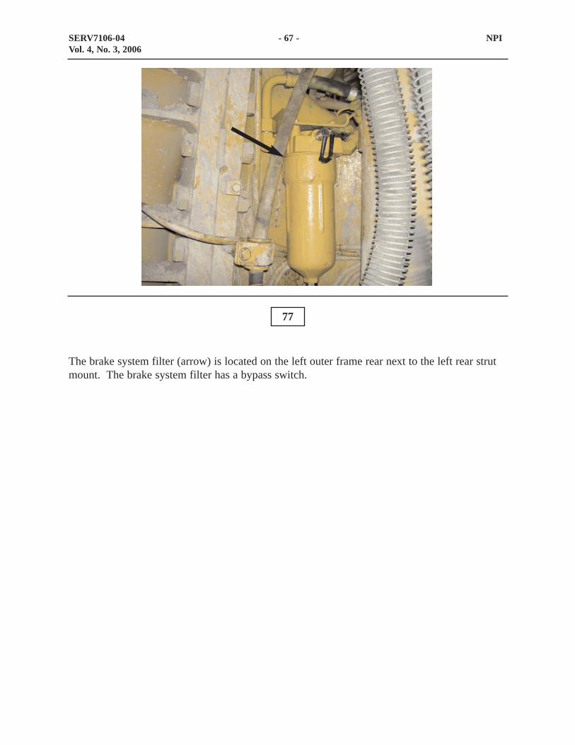
The brake system filter (arrow) is located on the left outer frame rear next to the left rear strutmount. The brake system filter has a bypass switch.
77
SERV7106-04 - 67 - NPIVol. 4, No. 3, 2006

The accumulator charging valve (1) is located on the left side of the frame by the brakeaccumulators This valve directs oil to the brake accumulators, brake cooling, and the tank.Once the accumulators are charged, the excess oil flow is sent to cool the brakes beforereturning to the tank.
The Brake ECM monitors the pressure in the service brake accumulators with pressure switch(2). If the pressure in the service brake accumulators are low, pressure switch (2) will open andthe Brake ECM will signal the monitoring system to turn on the brake system-check indicator
Pressure tap (3) is used to check the oil pressure in the service brake accumulators. Pressuretap (5) is used to check the charge oil pressure from the pump.
The accumulator charging valve contains a CUT-IN/CUT-OUT spool. Once the maximumbrake system pressure is reached, the spool will shift and send the excess flow to brake cooling.As the system pressure continues to drop to the CUT-IN pressure setting, the spool will shiftagain and the system will charge to the CUT-OUT pressure setting. This process will continueto repeat as often as needed to keep the brake system fully charged. The CUT-IN/CUT-OUTpressure is checked at pressure tap (3).
The relief valve (4) setting is set slightly higher than the CUT-OUT pressure setting. In theevent that the CUT-IN/CUT-OUT valve spool fails, the relief valve will protect the system fromextreme pressure. Relief valve (4) can only be tested on a hydraulic test bench.
If the charge oil pressure is low at pressure tap (5), or the brake system never reaches the properCUT-OUT pressure, check relief valve (4). If relief valve (4) is set properly and the brakesystem is not reaching the specified CUT-OUT pressure, replace the accumulator chargingvalve. The CUT-IN/CUT-OUT spool is not adjustable.
78
SERV7106-04 - 68 - NPIVol. 4, No. 3, 2006
1 2
43 5
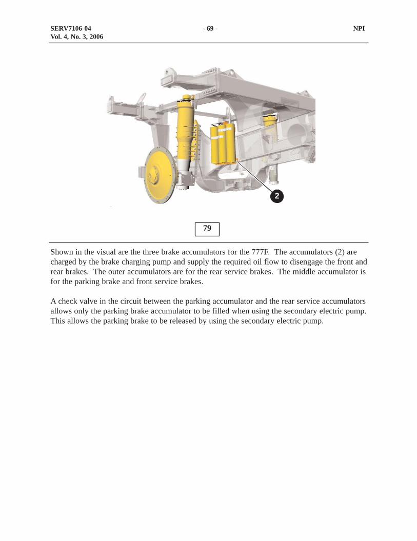
Shown in the visual are the three brake accumulators for the 777F. The accumulators (2) arecharged by the brake charging pump and supply the required oil flow to disengage the front andrear brakes. The outer accumulators are for the rear service brakes. The middle accumulator isfor the parking brake and front service brakes.
A check valve in the circuit between the parking accumulator and the rear service accumulatorsallows only the parking brake accumulator to be filled when using the secondary electric pump.This allows the parking brake to be released by using the secondary electric pump.
79
SERV7106-04 - 69 - NPIVol. 4, No. 3, 2006
2

The cab brake manifold (4) is mounted under the cab on the left upper frame. This manifoldcontains the ARC control solenoid (2) for the rear brakes and the ARC control solenoid (1) forthe front brakes.
The ARC control solenoid is part of the ARC system. The ARC system uses the rear servicebrakes and the front oil cooled brakes to automatically control the speed of the truck.
Also shown is the service brake pressure switch (3). This switch sends a signal to the BrakeECM whenever the service brakes are applied. The Brake ECM will use the signal frompressure switch (3) to turn on the brake lights. In a low pressure situation, the Brake ECM willsignal the monitoring system to activate the brake system-check indicator.
80
SERV7106-04 - 70 - NPIVol. 4, No. 3, 2006
1 2
3 4

The service brake valve (1) is mounted in the floor of the operator’s cab.
When the service brake pedal is depressed, the internal spool directs oil flow to the rear servicebrakes.
The secondary brake pedal (2) is used to apply the parking brakes if the service brakes are notresponding. The secondary brake pedal sends an electrical signal to the parking brake solenoid.
81
SERV7106-04 - 71 - NPIVol. 4, No. 3, 2006
1
2
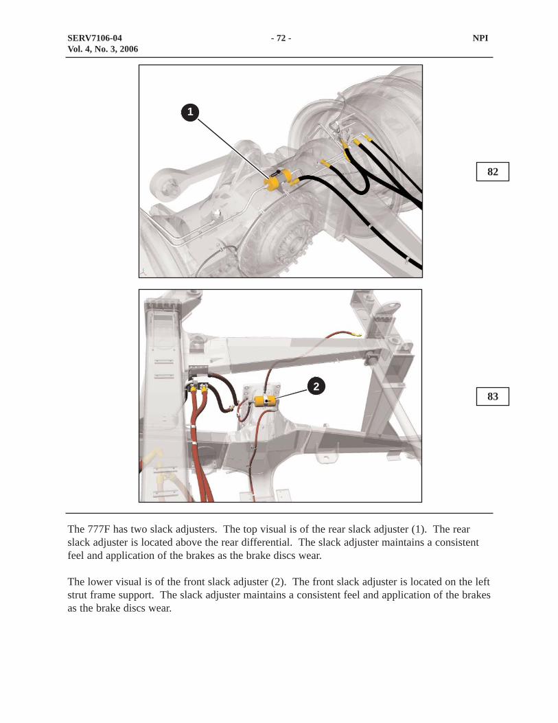
The 777F has two slack adjusters. The top visual is of the rear slack adjuster (1). The rearslack adjuster is located above the rear differential. The slack adjuster maintains a consistentfeel and application of the brakes as the brake discs wear.
The lower visual is of the front slack adjuster (2). The front slack adjuster is located on the leftstrut frame support. The slack adjuster maintains a consistent feel and application of the brakesas the brake discs wear.
82
83
SERV7106-04 - 72 - NPIVol. 4, No. 3, 2006
1
2
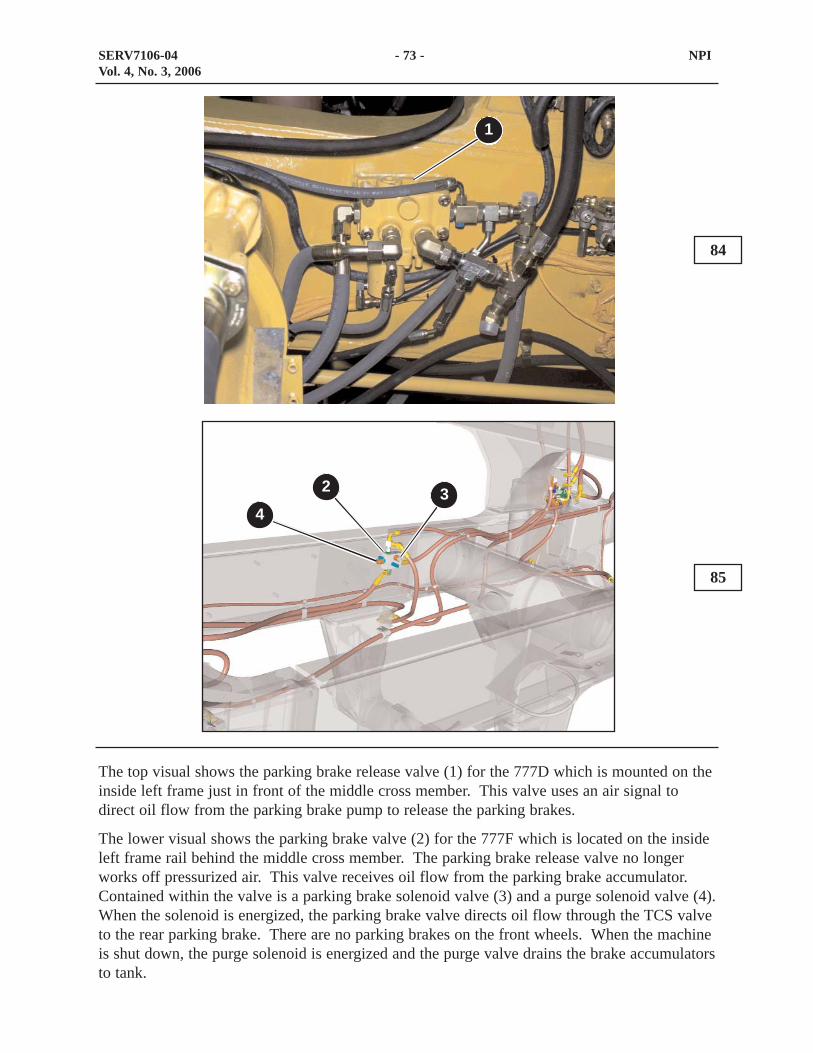
The top visual shows the parking brake release valve (1) for the 777D which is mounted on theinside left frame just in front of the middle cross member. This valve uses an air signal todirect oil flow from the parking brake pump to release the parking brakes.
The lower visual shows the parking brake valve (2) for the 777F which is located on the insideleft frame rail behind the middle cross member. The parking brake release valve no longerworks off pressurized air. This valve receives oil flow from the parking brake accumulator.Contained within the valve is a parking brake solenoid valve (3) and a purge solenoid valve (4).When the solenoid is energized, the parking brake valve directs oil flow through the TCS valveto the rear parking brake. There are no parking brakes on the front wheels. When the machineis shut down, the purge solenoid is energized and the purge valve drains the brake accumulatorsto tank.
84
85
SERV7106-04 - 73 - NPIVol. 4, No. 3, 2006
2 34
1

The TCS valve (1) is located inside the left frame rail toward the rear of the machine.
Parking brake oil flows through this valve before flowing to the parking brake in the rear wheelstations.
This valve remains unchanged from previous model trucks.
86
SERV7106-04 - 74 - NPIVol. 4, No. 3, 2006
1
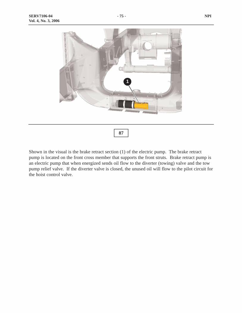
Shown in the visual is the brake retract section (1) of the electric pump. The brake retractpump is located on the front cross member that supports the front struts. Brake retract pump isan electric pump that when energized sends oil flow to the diverter (towing) valve and the towpump relief valve. If the diverter valve is closed, the unused oil will flow to the pilot circuit forthe hoist control valve.
87
SERV7106-04 - 75 - NPIVol. 4, No. 3, 2006
1

Shown in the top visual is the diverter (towing) valve (1) for the 777D. The diverter valve islocated on the left hoist cylinder frame support.
Shown in the lower visual is the diverter (towing) valve (2) for the 777F. The diverter valvefunctions the same however has changed locations. The diverter valve for the 777F is nowlocated on the left frame rail in front of the left front strut. The diverter valve must bemanually shifted before towing.
Once the valve is shifted, oil flow from the electric secondary pump is directed to the parkingbrake valve to release the parking brake. The relief valve (3) limits the maximum pressurewhen using the towing pump.
88
89
SERV7106-04 - 76 - NPIVol. 4, No. 3, 2006
1
2
3

CONCLUSION
This presentation has provided New Product Information (NPI) for the Caterpillar 777F Off-highway Trucks.
90
SERV7106-04 - 77 - NPIVol. 4, No. 3, 2006
91
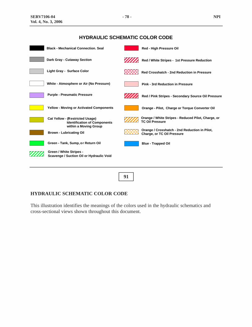
HYDRAULIC SCHEMATIC COLOR CODE
This illustration identifies the meanings of the colors used in the hydraulic schematics andcross-sectional views shown throughout this document.
SERV7106-04 - 78 - NPIVol. 4, No. 3, 2006
Red - High Pressure Oil
Red / White Stripes - 1st Pressure Reduction
Pink - 3rd Reduction in Pressure
Red / Pink Stripes - Secondary Source Oil Pressure
Orange - Pilot, Charge or Torque Converter Oil
Blue - Trapped Oil
Brown - Lubricating Oil
Cat Yellow - (Restricted Usage)
Green / White Stripes -Scavenge / Suction Oil or Hydraulic Void
Identification of Componentswithin a Moving Group
Black - Mechanical Connection. Seal
Dark Gray - Cutaway Section
Light Gray - Surface Color
White - Atmosphere or Air (No Pressure)
Purple - Pneumatic Pressure
Yellow - Moving or Activated Components
Orange / Crosshatch - 2nd Reduction in Pilot,Charge, or TC Oil Pressure
Orange / White Stripes - Reduced Pilot, Charge, orTC Oil Pressure
Red Crosshatch - 2nd Reduction in Pressure
Green - Tank, Sump, or Return Oil
HYDRAULIC SCHEMATIC COLOR CODE

Red
- H
igh
Pres
sure
Oil
Red
/ W
hite
Str
ipes
- 1
st P
ress
ure
Red
uctio
n
Pink
- 3r
d R
educ
tion
in P
ress
ure
Red
/ Pi
nk S
trip
es -
Seco
ndar
y So
urce
Oil
Pres
sure
Ora
nge
- Pilo
t, C
harg
e or
Tor
que
Con
vert
er O
il
Blu
e - T
rapp
ed O
il
Bro
wn
- Lub
ricat
ing
Oil
Cat
Yel
low
- (R
estr
icte
d U
sage
)
Gre
en /
Whi
te S
trip
es -
Scav
enge
/ Su
ctio
n O
il or
Hyd
raul
ic V
oid
Iden
tific
atio
n of
Com
pone
nts
with
in a
Mov
ing
Gro
up
Bla
ck -
Mec
hani
cal C
onne
ctio
n. S
eal
Dar
k G
ray
- Cut
away
Sec
tion
Ligh
t Gra
y -
Surf
ace
Col
or
Whi
te -
Atm
osph
ere
or A
ir (N
o Pr
essu
re)
Purp
le -
Pneu
mat
ic P
ress
ure
Yello
w -
Mov
ing
or A
ctiv
ated
Com
pone
nts
Ora
nge
/ Cro
ssha
tch
- 2nd
Red
uctio
n in
Pilo
t,C
harg
e, o
r TC
Oil
Pres
sure
Ora
nge
/ Whi
te S
trip
es -
Red
uced
Pilo
t, C
harg
e, o
rTC
Oil
Pres
sure
Red
Cro
ssha
tch
- 2nd
Red
uctio
n in
Pre
ssur
e
Gre
en -
Tank
, Sum
p, o
r Ret
urn
Oil
HYD
RA
ULI
C S
CH
EMAT
IC C
OLO
R C
OD
E
SERV7106-04 - 79 - Hand Out No. 1Vol. 4, No. 3, 2006