781301en-3 smartsigns compact 300 ifu
TRANSCRIPT

Spot Check Vital Signs Monitor
SC300

2
Notice
This document contains proprietary information that is protected by copyright. All Rights Reserved. Reproduction, adaptation, or translation without prior written permission is prohibited, except as allowed under the copyright laws.
Warranty
The information contained in this document is subject to change without notice.Huntleigh Healthcare Ltd makes no warranty of any kind with regard to this material, including, but not limited to, the implied warranties or merchantability and fi tness for a particular purpose.Huntleigh Healthcare Ltd shall not be liable for errors contained herein or for incidental or consequential damages in connection with the furnishing, performance, or use of this material.
Revision History
The documentation part number and revision number indicate its current edition. The revision number changes when a new edition is printed in accordance with the revision history of the documentation. Minor corrections and updates which are incorporated at reprint do not cause the revision number to change. The document part number changes when extensive technical changes are incorporated.

3
Tabl
e of
Con
tent
sContents1. General Safety Information ................................................5
1.1 Warnings / Cautions ............................................................................................. 52. Introduction ........................................................................8
2.1 Features of the Smartsigns® Compact 300 .................................................... 82.2 Intended Use .................................................................................................. 92.3 About This Manual ......................................................................................... 9
3. Description of Controls, Indicators,Symbols and Displays ..............................................................................10
3.1 Identifi cation of Front Panel Controls and Symbols ....................................... 103.2 Identifi cation of rear panel controls ............................................................... 113.3 Identifi cation of Side panel controls .............................................................. 113.4 Identifi cation of Underside ............................................................................ 123.5 Description of Symbols/ Indicators ................................................................. 123.6 Description of Controls ................................................................................... 14
4. Setting up the Monitor ........................................................154.1 Unpacking and Inspection .............................................................................. 164.2 List of Components ........................................................................................ 164.3 Power Cable Connections ............................................................................. 174.4 Connecting Accessories ................................................................................. 18
5. Battery Operation ...............................................................205.1 Installing the Battery pack .............................................................................. 205.2 Operating on Battery Power ........................................................................... 215.3 Charging a low battery ................................................................................... 215.4 Battery Using Guidance ................................................................................. 21
6. System Display ...................................................................227. Using the Monitor ...............................................................24
7.1 Turning the Monitor ON .................................................................................. 247.2 Performing Power On and Self-Test (POST) ................................................. 257.3 Turning the Monitor OFF ................................................................................ 25
8. System Settings .................................................................268.1 Measuring Mode ............................................................................................ 268.2 Review Mode ................................................................................................. 26 8.3 Pulse Tone Setting ......................................................................................... 278.4 Standby Mode ................................................................................................ 278.5 Exiting Standby Mode .................................................................................... 278.6 Maintenance Mode ........................................................................................ 28
9. NIBP Monitoring ..................................................................319.1 General .......................................................................................................... 329.2 Setup Connections ......................................................................................... 329.3 Starting / Stopping Measurements ................................................................. 349.4 Automatic Measurements .............................................................................. 34
10. SpO2/Pulse Rate Monitoring .............................................3610.1 General Principles of Measuring SpO2 Plethysmography Parameter ............ 3710.2 Identifying the SpO2 Module .......................................................................... 3810.3 Setup Connections ......................................................................................... 3810.4 SpO2 and Pulse Rate Display ....................................................................... 39
4
Tabl
e of
Con
tent
s 11. Temperature Monitoring ...................................................4011.1 Description of the Thermometer IRT10 .......................................................... 4011.2 Thermometer Display ..................................................................................... 4111.3 Main Unit Display ........................................................................................... 4111.4 Pairing the Thermometer and Main Unit ........................................................ 4211.5 Temp Measurement ....................................................................................... 42
12. Maintenance .....................................................................4312.1 General .......................................................................................................... 4312.2 Returning the Smartsigns® Compact 300 and System Components ............. 4312.3 Service ........................................................................................................... 4312.4 Periodic Safety Checks .................................................................................. 4312.5 Cleaning ......................................................................................................... 4412.6 Battery maintenance ...................................................................................... 44
13. Troubleshooting ................................................................4513.1 General .......................................................................................................... 4513.2 Corrective Action ............................................................................................ 4813.3 Obtaining Technical Assistance ..................................................................... 48
14. Electromagnetic Compatibility ........................................4915. Specifi cations ...................................................................53
15.1 Equipment Classifi cation ............................................................................... 5315.2 Standards ....................................................................................................... 5315.3 General .......................................................................................................... 5315.4 Electrical ........................................................................................................ 5415.5 Environmental ................................................................................................ 5415.6 Measurement Parameters ............................................................................. 55
16. Accessories ......................................................................5717. End of Life Disposal ..........................................................5918. Warranty & Service ..........................................................60
18.1 Service Returns ............................................................................................. 60

5
1. General Safety InformationThis section contains important safety information related to general use of the Smartsigns® Compact 300 vital signs monitor. Other important safety information appears throughout the manual
Important! Before using this equipment, please study this manual carefully and familiarise yourself with the controls, display features and operating techniques. Ensure each user fully understands the safety and operation of the unit, as misuse may cause damage to the unit or injury to the user or patient.
1.1 Warnings / Cautions
General warning / caution
Refer to Instructions for Use
WARNING: In the USA, do not connect to an electrical outlet controlled by a wall switch as the device may be accidentally turned off.
WARNING: If in doubt about the integrity of the AC power source, the monitor must be operated from its internal battery.WARNING: As with any medical equipment, carefully route patient cabling to reduce the possibility of patient entanglement or strangulation.
WARNING: If the monitor does not shut down properly, the settings return to factory defaults.
WARNING: Check the equipment prior to use and ensure its safe and proper use.
WARNING: Do not autoclave the monitor.
WARNING: Explosion hazard. Do not use the unit in the presence of fl ammable anaesthetics or gases. Do not operate in a hyperbaric chamber, in oxygen-enriched environments, or in any other potentially explosive environment.
WARNING: Before use, carefully read the accessories instructions for use, including all warnings, cautions, and instructions.
WARNING: Do not use damaged cuffs, sensors and other cables. Do not immerse cuffs, sensors and other cables completely in water, solvents, or cleaning solutions as the connectors are not waterproof. Do not sterilize cuffs, sensors and other cables by irradiation, steam, or ethylene oxide. Refer to each cleaning instructions in the directions for use.
Gen
eral
Saf
ety
Info
rmat
ion

6
WARNING: If the battery shows any signs of damage, leakage, or cracking, it must be replaced immediately, by a qualifi ed service person, and only with a battery approved by the manufacturer.
WARNING: The monitor is intended only as an adjunct in patient assessment. It must be used in conjunction with clinical signs and symptoms.
WARNING: The measurement of vital signs can be affected by patient conditions, motions, sensors, environmental condition and electromagnetic external condition.WARNING: It is possible that any radio frequency transmitting equipment and other sources of electrical noise such as cellular phones, due to close proximity or strength of a source, may result in disruption of performance.
WARNING: To ensure patient safety, do not place the monitor in any position that might cause it to fall on the patient.
WARNING: Disconnect the monitor and sensors during magnetic resonance imaging (MRI) scanning. Use during MRI could cause burns or adversely affect the MRI image or the monitor’s accuracy. Also, to avoid burns, remove the sensors from the patient before conducting MRI.WARNING: During prolonged and continuous SpO2 monitoring, check the sensor site at least once every 4 hours. Inspect the patient’s skin integrity and circulation, and relocate the sensor if necessary. Tissue damage can result from improper or prolonged sensor attachment.
WARNING: Do not lift the monitor by a sensor cable or a power cord because the cable could disconnect from the monitor, causing the monitor to drop on the patient.
WARNING: The unit may not operate effectively on patients who are experiencing convulsions or tremors.
WARNING: Do not connect more than one patient to the monitor.
CAUTION: U.S. Federal law restricts this device to sale by or on the order of a licensed healthcare practitioner.
CAUTION: Exercise care for the safe and effective use of Smartsigns® Compact 300 monitor. Inaccurate data may be measured if operated or stored at conditions outside the stated ranges, or subjected to excessive shock or dropping.CAUTION: Grounding reliability can only be achieved when equipment is connected to an equivalent receptacle marked ‘Hospital Only’ or ‘Hospital Grade’.CAUTION: The accuracy of the monitor may degrade if the monitor is connected to secondary I/O devices when the monitor is not connected to earth reference.CAUTION: Never place fl uids on the monitor. In case of fl uid spilling on the monitor, disconnect power cord, wipe clean immediately and have the monitor serviced to ensure that no hazard exists.
Gen
eral
Saf
ety
Info
rmat
ion

7
CAUTION: The monitor may display error codes when outside of the measurable range occur.
CAUTION: Accessory equipment connected to the monitor’s data interface must be certifi ed according to IEC60950 for data processing equipment or IEC60601-1 for electromedical equipment. All combinations of equipment must be in compliance with IEC60601-1-1 system requirements. Anyone who connects additional equipment to the signal input or signal output port confi gures a medical system and is therefore responsible that the system complies with the requirements of IEC60601-1-1 and the electromagnetic compatibility standard IEC60601-1-2. If in doubt, contact Huntleigh Healthcare Service Department.
Gen
eral
Saf
ety
Info
rmat
ion

8
2. IntroductionWARNING: The Smartsigns® Compact 300 is intended only as an adjunct in patient assessment. It must be used in conjunction with clinical signs and symptoms.
This manual contains information about the Smartsigns® Compact 300 vital signs monitor. The Smartsigns® Compact 300 is available in the following confi gurations:
Confi g. Features
SC300 NiBP, Pulse & SpO2
SC300T NiBP, Pulse, SpO2 & Temperature
SC300N NiBP, Pulse & SpO2 (NELLCOR)
SC300NT NiBP, Pulse, SpO2 (NELLCOR) & Temperature
Note: Refer to Specifi cation Section for more information about each confi guration.
All information in this manual, including the illustrations, are based on a monitor confi gured with the NIBP, SpO2 and Temperature options. If your monitor confi guration lacks any of these options, certain information in this manual does not apply.
2.1 Features of the Smartsigns® Compact 300
Physical
The Smartsigns Compact 300 series is a small lightweight SPOT check vital signs monitor. It measures 130mm x 125mm x 219 mm and weighs 1.25 Kg. The integrated carry handle allows the unit to be hand carried between locations.
Electrical
The monitor is powered either by the local mains supply (100 – 240 VAC 50/60Hz) or an internal 2200 mAh lithium Ion battery.The internal batteries are charged whenever the SC300 is connected to the local supply.
Display
The monitor uses a 6” LED type of numerical display to display patient and system status.
Auxiliary Outputs
The monitor provides an RS-232 I/O facility on the rear of the unit, this is used for software upgrades.
Intr
oduc
tion
9
2.2 Intended Use
The Smartsigns Compact 300 Series is intended for use by trained healthcare professional in healthcare settings to monitor physiologic status of Adult, Paediatric and Neonatal patients.Physiologic measurements include:
• Non invasive blood pressure (NiBP)• Pulse oximetry• Pulse rate• Temperature
Note: Hospital use typically covers such areas as general care fl oors, operating rooms, special procedure areas, intensive and critical care areas, within the hospital plus hospital-type facilities. Hospital-type facilities include physician offi ce based facilities, sleep labs, skilled nursing facilities, surgicenters, and sub-acutecenters.
Note: Intra-hospital transport includes transport of a patient within the hospital or hospital-type facility.
Note: The medically skilled and trained user can be clinicians like doctors and nurses who know how to take and interpret a patient’s vital signs. These clinicians must take direct responsibility for the patient’s life. This can include care-givers or medically trained interpreters who are authorised under the appropriate clinical facility procedures to support patient care. Any inappropriate setting, can lead to a hazardous situation that injures, harms or threatens the patient’s life. This equipment should only be operated by trained users who can adjust the settings of the monitor.
2.3 About This Manual
This manual explains how to set up and use the Smartsigns® Compact 300 vital signs monitor. Important safety information relating to general use of the monitor appears before this introduction. Other important safety information is located throughout the text where applicable.
Read the entire manual including the Safety Information section, before you operate the monitor.
This manual is compatible with units fi tted with Version 3.0 software and above.
Intr
oduc
tion

10
3. Description of Controls, Indicators, Symbols and Displays3.1 Identifi cation of Front Panel Controls and Symbols
4
2
1
3
8
56
7
1 Carry handle
2 Display
3 ON / OFF
4
Battery Indicator
• ON: Battery is being charged, or fully charged• OFF: Battery is not fi tted or faulty• FLASHING: The battery is supplying power to the monitor.
AC Power Indicator• ON: Monitor is connected to AC power• OFF: Monitor is not connected to AC power
5 Return
6 Patient group selection
7 Start / Stop NiBP
8 Wireless infrared thermometer
Des
crip
tion
of
Con
trol
s, I
ndic
ator
s, S
ymbo
ls a
nd D
ispl
ays

11
3.2 Identifi cation of rear panel controls
1 Loudspeaker
2 Equipotential post
3 RS232 Service port
4 AC Power connector
5 Product identifi cation label
4
2
1
35
3.3 Identifi cation of Side panel controls
1 NiBP connector
2 SpO2 connector
1 Wireless Infra red thermometer IRT10 (option)
2 Thermometer lens (option)
Left Right
2
1
2
1
Des
crip
tion
of
Con
trol
s, I
ndic
ator
s, S
ymbo
ls a
nd D
ispl
ays
12
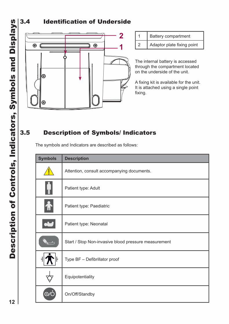
3.4 Identifi cation of Underside
1 Battery compartment
2 Adaptor plate fi xing point
The internal battery is accessed through the compartment located on the underside of the unit.
A fi xing kit is available for the unit. It is attached using a single point fi xing.
21
3.5 Description of Symbols/ Indicators
The symbols and Indicators are described as follows:
Symbols Description
Attention, consult accompanying documents.
Patient type: Adult
Patient type: Paediatric
Patient type: Neonatal
Start / Stop Non-invasive blood pressure measurement
Type BF – Defi brillator proof
Equipotentiality
On/Off/Standby
Des
crip
tion
of
Con
trol
s, I
ndic
ator
s, S
ymbo
ls a
nd D
ispl
ays
13
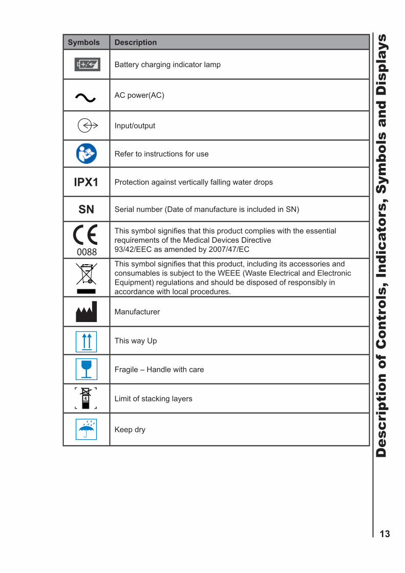
Symbols Description
Battery charging indicator lamp
AC power(AC)
Input/output
Refer to instructions for use
IPX1 Protection against vertically falling water drops
SN Serial number (Date of manufacture is included in SN)
This symbol signifi es that this product complies with the essential requirements of the Medical Devices Directive 93/42/EEC as amended by 2007/47/EC
This symbol signifi es that this product, including its accessories and consumables is subject to the WEEE (Waste Electrical and Electronic Equipment) regulations and should be disposed of responsibly in accordance with local procedures.
Manufacturer
This way Up
Fragile – Handle with care
Limit of stacking layers
Keep dry
Des
crip
tion
of
Con
trol
s, I
ndic
ator
s, S
ymbo
ls a
nd D
ispl
ays

14
3.6 Description of Controls
Controls Description
ON/OFF/STANDBY Key
• Press this button to start the system – the system status indicator will illuminate green.• When in measurement mode, press this button to enter standby mode – the system indicator changes to amber.• To switch OFF, press and hold this button for 2s.Return key
Error code clearance• Press this key to clear any error code which may be displayed when in measurement mode.
Save measurement• Press this key to save measurement to memory
Memory re-call• Press and hold this key for 2s to access stored measurements in the memory
Pulse tone enable / disable• Press and hold this key for 4s to enable the pulse tone setting (on / off)
Maintenance mode selection• Press this key within 10s of power up to enter the maintenance mode.Patient Group select key
Patient selection
• Press this key to select the relevant patient group.
Start/Stop NIBP Measurement
• Press this key to initiate a blood pressure measurement, If the button is pressed during a measurement, the measurement will stop.D
escr
ipti
on o
f C
ontr
ols,
Ind
icat
ors,
Sym
bols
and
Dis
play
s

15
4. Setting up the MonitorWARNING: The Smartsigns® Compact 300 is a prescription device and is to be operated by qualifi ed personnel only. It is designed for use by medical clinicians. Although this document might illustrate medical monitoring techniques, the monitor must be used only by trained clinicians who know how to take and interpret a patient’s vital signs.WARNING: In the USA, do not connect to an electrical outlet controlled by a wall switch because the device may be accidentally turned off.
WARNING: As with all medical equipment, carefully route patient cabling to reduce the possibility of patient entanglement or strangulation.
WARNING: To ensure patient safety, do not place the monitor in any position that might cause it to fall on the patient.
WARNING: Do not lift the monitor by the sensor cables or power cord because the cable could disconnect from the monitor, causing the monitor to drop on the patient.
WARNING: Disconnect the monitor and sensors/cables during magnetic resonance imaging (MRI) scanning. Using the monitor during MRI may cause burns or adversely affect the MRI image or the monitor’s accuracy.
WARNING: To ensure accurate performance or prevent device failure do not subject the monitor to extreme moisture, such as direct exposure to rain. Such exposure may cause inaccurate performance or device failure
WARNING: Do not use the Smartsigns® Compact 300 vital signs monitor, SpO2 sensors, temperature probes or connectors that appear damaged.
WARNING: Discarded battery may explode during incineration. Follow local government ordinances and recycle instructions regarding disposal or recycling of device components, including batteries.
WARNING: Do not touch the monitor when a defi brillator is being discharged (electrifi ed), as doing so may cause electric shock.
WARNING: Ensure that the speaker is clear of any obstruction. Failure to do so could result in an inaudible tone.CAUTION: If the Smartsigns® Compact 300 is to be stored for a period of 2 months or longer, it is recommended to notify service personnel to remove the battery from the monitor prior to storage. Recharging the battery is strongly recommended when the battery has not been recharged for 2 or more months.CAUTION: Recycle used batteries properly. Do not dispose of batteries in refuse containers.
Set
ting
up
the
Mon
itor

16
4.1 Unpacking and Inspection
The Smartsigns® Compact 300 vital signs monitor is shipped in one carton. Examine the carton carefully for evidence of damage. Contact Huntleigh Healthcare Ltd Service Department immediately if any damage is discovered. Return all packing material and monitor. Refer to the Maintenance section for instructions on returning damaged items.
Set the monitor to the user’s intended position where the user can easily recognise the visual and audible monitoring conditions.
4.2 List of Components
Quantity Item
1 Smartsigns Compact 300 Spot Check Vital Signs Monitor1 NiBP Cuff Adult ( 25 – 35 cm)1 NiBP hose1 SpO2 sensor1 Wireless thermometer (Optional)1 Thermometer lens - pack 20 pcs (Optional)1 Operator’s manual1 Power cord (country specifi c)
1 Grounding wire
A range of accessories are available for the Smartsigns Compact 300 series, please contact your distributor or the customer services Department for more information.
Set
ting
up
the
Mon
itor

17
4.3 Power Cable Connections
WARNING: In the USA, do not connect to an electrical outlet controlled by a wall switch because the device may be accidentally turned off.
CAUTION: For the safety of patients, use only a Huntleigh Healthcare Ltd supplied power cord. Using a non approved power cord can damage the monitor, and will void the product warranty. If in doubt about the integrity of the AC power source, the monitor must be operated from its internal battery.
AC Power
Ensure that the AC outlet is properly grounded and that it is in the specifi ed voltage and frequent range (100 – 240 VAC, 50-60 Hz).
1 AC inlet
2 Equipotential point
21
1. Connect the female connector end of the AC power cord to the monitor rear panel connector. 2. Plug the male connector end of the AC power cord into a suitably grounded AC outlet. 3. Verify that the Charging/AC Indicator is lit. 4. If necessary, connect the grounding wire. Connect the grounding wire connector to the equipotential terminal on the rear panel. Attach the clip end of the grounding wire to the medical equipment grounding terminal on the wall.
Set
ting
up
the
Mon
itor

18
4.4 Connecting Accessories
WARNING: Do not lift the monitor by the sensor cables, or power cord because the cable could disconnect from the monitor, causing the monitor to drop on the patient.Note: For the safety of patients, and to ensure the best product performance and accuracy, use accessories provided with the Smartsigns® Compact 300 only, or accessories recommended by Huntleigh Healthcare Ltd Service Department.
NIBP Hoses and Cuffs
NIBP Hose Connector
1. Select the appropriate size cuff for the patient and apply the cuff to the selected site. 2. Connect the hose to the NiBP connector on the side of the unit.
SpO2 Cables and Sensors
SpO2 Interface cable connector
1. Select an appropriate sensor for the patient and desired application. 2. Apply the sensor to the selected site. 3. Connect the SpO2 sensor to the side of the unit.
Set
ting
up
the
Mon
itor

19
Wireless thermometer (Option)
1
2
3
4
5
6
1 Status indicator
2 Start measurement
3 Display
4 Infra red sensor
5 Lens ejector
6 Battery compartment
Set
ting
up
the
Mon
itor

20
5. Battery OperationWARNING: Dispose of Battery in accordance with local requirements and regulation. Follow local instructions regarding disposal or recycling of batteries.CAUTION: If the Smartsigns® Compact 300 is to be stored for a period of 2 months or longer, it is recommended to notify service personnel to remove the battery from the monitor prior to storage. Recharging the battery is strongly recommended when it has not been recharged for 2 or more months
CAUTION: Measured or displayed data may not be assured in the low battery or the critical low battery condition.
CAUTION: Discarded battery may explode during incineration. Recycle used batteries properly. Do not dispose of batteries in refuse containers.
Note: As the battery is used and recharged over a period of time, the amount of time between the onset of the low battery alarm and the instrument shut-off may become shorter. It is recommended for service personnel to check periodically or replace of internal battery if necessary.
Note: It is recommended that the monitor remain connected to AC power source when not in use. This will ensure a fully charged battery whenever it is needed.
5.1 Installing the Battery pack
The monitor has an internal Lithium Ion rechargeable battery which can power the unit when an AC power source is not available.
Turn the monitor OFF, disconnect the power cord and any accessory.Place the monitor on a surface and place upright with the base exposed.Unscrew the battery cover, offer the battery into the battery compartment making sure the positive and negative terminals are connected correctly.Replace the battery cover and secure, turn the monitor upright.
Bat
tery
Ope
rati
on

21
5.2 Operating on Battery Power
With NiBP measurements taken at 15 minute intervals, the operating time for a fully charged battery pack is nominally 12 hours.When connected to the AC power supply, the battery is automatically charged.The battery icon shown on the screen will indicate the battery status:
Battery indicator Status
Battery is fully charged
& Battery is charged but not at maximum level
Battery requires recharging
If the battery symbol fl ashes, it indicates that the battery needs to be charged immediately. The fl ashing symbol is also accompanied with an audible alert.
5.3 Charging a low battery
Connect the monitor to the local AC supply, charging is automatic.During the charging process, the battery charging indicator lamp illuminates green. On reaching full capacity the battery charging indicator lamp will extinguish.The typical charging time of the lithium-ion battery is:
• With the monitor switched OFF, the recharge time is less than 3 hours.• With the monitor switched ON, the recharge time is no longer than 5.5 hours.
5.4 Battery Using Guidance
Life expectancy of the battery depends on how frequent and how long it is used. For a properly maintained and stored lithium-ion battery, its service life is approximately 3 years. With more frequent and aggressive use, the life expectancy can be less. We recommend replacing lithium-ion batteries every 3 years.
Bat
tery
Ope
rati
on

22
6. System DisplayThe display is organised into a series of zones
12
3
4
5
9
6
78
19
10 11 12
18
17
16
15
14
13
Sys
tem
Dis
play

23
Item Description
1 System timeSet the time - Year, Month, Date, Hour, Minute
2 Patient measurement data review50 sets data can be stored in the monitor
3 NIBP measurement unitsmmHg or kPa.
4 MAP - Mean arterial blood pressure reading
5 Pulse rate – derived from NiBP measurement
6
SpO2 sensor status:Own brand SpO2:• Icon fl ash: Poor fi nger connection, or sensor is disconnectedNellcor SpO2• Icon off: Probe is off• Icon fl ash: Poor fi nger connection or sensor is disconnected
7 SpO2 measurement (Rotating digits is searching for a pulse).
8 Relative indication of signal strength
9 Temperature measurement
10 Temperature units (ºC or ºF)
11 Temperature reading
12Wireless connection indicator – temperature sensorON: Temperature sensor pairedOFF: Temperature sensor NOT paired
13 Pulse rate – derived from the SpO2 sensor
14 Pulse rate symbol
15 Diastolic blood pressure measurement
16 Systolic blood pressure measurement
17 Battery indicator.
18 Patient type (neonate, paediatric, adult)
19 Error code
Sys
tem
Dis
play
24
7. Using the Monitor
WARNING: If the POST (power on self-test) is not completed successfully, do not use the monitor.
WARNING: Ensure that the speaker is clear of any obstructions. Failure to do so could result in an inaudible alarm tone.
WARNING: Disconnect the monitor and sensors/cables during magnetic resonance imaging (MRI) scanning. Using the monitor during MRI may cause burns or adversely affect the MRI image or the monitor’s accuracy.
WARNING: The Smartsigns® Compact 300 is intended only as an adjunct in patient assessment. It must be used in conjunction with clinical signs and symptoms.
WARNING: The Smartsigns® Compact 300 is a prescription device and is to be operated by qualifi ed personnel only. It is designed for use by medical clinicians. Although this document might illustrate medical monitoring techniques, the monitor must be used only by trained clinicians who know how to take and interpret a patient’s vital signs.
7.1 Turning the Monitor ON
Before using the Smartsigns® Compact 300, verify that the monitor is working properly and is safe to use. Proper working condition will be verifi ed each time the monitor is turned on as described in the following procedure.
Note: Physiological conditions, medical procedures, or external agents that may interfere with the monitor’s ability to detect and display measurements, include dysfunctional haemoglobin, arterial dyes, low perfusion, dark pigment, and externally applied colouring agents such as nail polish, dye, or pigmented cream.
Note: The parameters may be set on an individual basis, by the clinician, and these settings will remain in effect until the monitor is turned off.
Usi
ng t
he M
onit
or

25
7.2 Performing Power On and Self-Test (POST)
CAUTION: The Smartsigns® Compact 300 automatically starts the Power-On-Self-Test, which tests the monitor circuitry and functions. During POST (immediately after power-up), confi rm that all display segments and indicators are illuminated and the power on beep tone sounds.CAUTION: If any indicator or display element does not light, or the speaker does not sound, do not use the monitor. Contact qualifi ed service personnel or Huntleigh Healthcare Ltd Service Department.
1. Turn the monitor ON by pressing the ON/OFF/STAND BY button.2. The monitor automatically starts the Power On Self Test (POST), which tests the system integrity.3. Verify that the monitor sounds a confi rmation tone during power up and each section of the display is illuminated.
Power On Self Test
4. Should the system detect an internal problem, the system will display an error code on the display. Contact a qualifi ed service person5. Upon completion of the POST, the monitor will enter the MEASUREMENT MODE.
7.3 Turning the Monitor OFF
To switch the system OFF, follow the steps blow,1. Ensure the monitoring session has fi nished.2. Disconnect all accessories from the patient.3. Press and hold the ON/OFF/STAND BY key for 2s, the system will shut down.
Usi
ng t
he M
onit
or

26
8. System SettingsThe Smartsigns Compact 300 Series provides multiple working modes for its users
• Measurement mode – Take measurements • Review mode – View saved measurements• Parameter setting mode – Set pulse tone ON or OFF• Maintenance mode – Adjust system settings• Standby mode - Sleep
Each mode offers different facilities and access to different settings.
8.1 Measuring Mode
After the initial startup, the system defaults to the measurement mode.
From here the user can undertake a series of measurements.
1. Press to start the NIBP measurement.
2. Apply the SpO2 sensor to the patient, after a short period, the SpO2 measurement will be displayed on the screen.
3. Apply a new infrared lens cover to the tip of the Thermometer, temperature measurements can now be made
4. After making a measurement, data will be displayed in the corresponding area on the display.
5. Press to save the measurement to memory.
6. After measuring one or multiple parameters, data will be automatically saved if there is no additional measurement made within 2 minutes.
8.2 Review Mode
In the measuring mode, press for 2s to enter review mode; in this mode, up to 50 sets measurement data can be reviewed. Measurements are stored in date and time order.
1. Press to cycle through the stored measurements, the oldest measurement will be displayed fi rst.
2. Press to return to the measurement mode.
This monitor saves up to 50 measurements.
Sys
tem
Set
ting
s

27
8.3 Pulse Tone Setting
1. In the measuring mode, press and hold for 4s to enter the pulse tone setting.
2. The PR value will fl ash
3. Press to switch pulse sound on or off.
4. Press to save the setting and return to the measurement mode.
8.4 Standby Mode
Press to enter the standby mode.
The monitor will automatically enter the standby mode if there is no activity for 10 minutes.
The monitor will automatically shut down if it remains in standby mode for more than 30 minutes
When the unit is in standby mode, the display will be switched off and the ON/OFF/STANDBY key backlight will be illuminated amber.
8.5 Exiting Standby Mode
To exit the standby mode, press any key. Additionally, the system will automatically exit standby if:
1. The monitor receives an input from the SpO2 sensor.
2. The power is too low ( )
3. Receives a temperature measurementS
yste
m S
etti
ngs

28
8.6 Maintenance Mode
The maintenance mode is intended for use of a biomedical technician or suitably qualifi ed person. It is unlikely that healthcare professionals or clinicians would need to access this mode.
To enter the maintenance mode, press the key within 10s of switching the system ON.
The system will display the fi rmware revision in each of the corresponding sections of the display.
In this mode, the user can access the fl owing settings:
a) NIBP units of measure
b) Temp units of measure
c) System date & time
d) NIBP leak test
e) NIBP pressure test
f) Display brightness
g) Restoration of the factory default settings.
Having made a change, Press and hold to shut the monitor down. The new settings will take effect when the monitor is restarted.
NIBP Units Setting
Enter the maintenance mode;
1. Press or to alternate between mmHg or kPa.
2. Make the selection and press and hold to shut the monitor down or to move to the next setting.
Temp Units Setting
Enter the maintenance mode;
1. Press and switch to the TEMP unit setting area
2. Press or to switch between ºC or ºF
3. Make the selection and press and hold to shut the monitor down or to move to the next setting.
Sys
tem
Set
ting
s

29
System Date & Time Setting
Enter the maintenance mode;
Year1. Press twice to enter the ” year” setting area;
2. Press to increase the value
3. Press to decrease the value
Month/Day
1. Press to enter the ”Month” setting
2. Press to increase the value
3. Press to decrease the value
4. Press to enter the ”Day” setting
5. Press to increase the value
3. Press to decrease the value
Hour/Minute
1. Press to enter the ”Hour” setting
2. Press to increase the value
3. Press to decrease the value
4. Press to enter the ”Minute” setting
5. Press to increase the value
3. Press to decrease the value
Having made the selection, press to exit the date and time setting.
NIBP Module Testing
This adjustment is reserved for service personnel
Enter the maintenance mode.
1. Press until the PR bpm display begins to fl ash
2. Press to switch between the leak test or pressure test
“150” selects the NIBP leak test; “250” selects the NIBP pressure testing.
3. Press to start each test.
Sys
tem
Set
ting
s

30
Brightness Adjust
This adjustment is reserved for service personnel
Enter the maintenance mode
1. Press repeatedly until the brightness adjustment setting begins to fl ash.
2. Press or to adjust the display brightness – 05 being maximum brightness.
Restoring Factory Default settings
This adjustment is reserved for service personnel
Enter the maintenance mode;
1. Press repeatedly until 00 is displayed in the PR bpm area.2. Although the factory default settings cannot be changed, the user can assign a different confi guration to the local default settings.
3. To restore the confi guration to the default factory settings, press to select 00.
The factory default settings are:
Unit Default settingNiBP units mmHgTemperature Units ºCPatient Type AdultBeep Tone ON
Sys
tem
Set
ting
s

31
9. NIBP Monitoring
For the safety of patients, and to ensure the best product performance and accuracy, use only the cuffs and the hose provided with the monitor, or recommended by Huntleigh Healthcare Ltd Service Department. Using other cuffs or hoses may result in inaccuracies.
Inaccurate measurements may be caused by incorrect cuff application or use, such as placing the cuff too loosely on the patient, using the incorrect cuff size, or not placing the cuff at the same level as the heart, leaky cuff or hose, and excessive patient motion.
Keep patients under close surveillance when monitoring. It is possible, although unlikely, that radiated electromagnetic signals from sources external to the patient and monitor can cause inaccurate measurement readings. Do not rely entirely on the Smartsigns® Compact 300 readings for patient assessment.
The Smartsigns® Compact 300 is not intended for diagnostic treatment. To ensure patient safety, use other diagnosis equipment.
Any excessive patient motion may cause inaccurate measurements of non-invasive blood pressure. Make sure there is no patient motion affected to blood pressure measurements.
The blood pressure cuff should not be applied to the same extremity as the one to which an SpO2 sensor is attached, since cuff infl ation will disrupt SpO2 monitoring.
Check the patient’s limb on which the cuff is applied to assure that circulation is not constricted. Constriction of circulation is indicated by discolouration of the extremity. This check should be performed at the clinician’s discretion at regular intervals based on the circumstances of the specifi c situation.In some cases, rapid, prolonged cycling of a blood pressure monitor cuff has been associated with any or all of the following: ischemia, purpura, or neuropathy. Apply the cuff appropriately, according to instructions, and check the cuff site and extremity regularly when blood pressure is measured at frequent intervals or over extended periods of time.Never place the cuff on extremity being used for intravenous infusion or any area where circulation is compromised or has the potential to be compromised. Never fi t NIBP system with Luer Lock adapters that can be connected to IBP or injection systems.
As with all automatically infl atable blood pressure devices, continual cuff measurements can cause injury to the patient being monitored.
During use on patients, ensure that heavy objects are not placed on the hose. Avoid crimping or undue bending, twisting, or entanglement of the hose.
Never use an adult or paediatric monitor setting or cuff for an NIBP measurement on a neonatal patient. Adult and paediatric infl ation limits can be excessive for neonatal patients, even if a neonatal cuff is used.
NIBP readings may be inaccurate for patients experiencing moderate to severe arrhythmia.
NIB
P M
onit
orin
g

32
Do not touch the monitor when a defi brillator is being discharged (electrifi ed), as doing so may cause electric shock.
Continual cycling of the BP cuff may in extreme situations cause harm to the patient. Assess the advantages of frequent measurements in particular the use of CO mode against the potential risk of injury.
Note: A patient’s vital signs may vary during administration of agents affecting the cardiovascular system, such as those used to raise or lower blood pressure or raise or lower heart rate.
Note: Blood pressure measurements can be affected by the position of the patient, the patient’s physiological condition, and other factors.
9.1 General
NIBP processing by the monitor uses the oscillometric measuring technique. A motorized pump infl ates the cuff to initially block the fl ow of blood in the extremity. Then, under monitor control, the pressure in the cuff is gradually reduced, while a pressure transducer detects air pressure and transmits a signal to the NIBP circuitry.
When the cuff pressure is still above systolic pressure, small pulses or oscillations in the cuff pressure begin to be sensed by the transducer. As the cuff continues to defl ate, oscillation amplitude increases to a maximum and then decreases. When maximum oscillation amplitude occurs, the cuff pressure at that time is measured as mean arterial pressure (MAP). The systolic and diastolic pressures are calculated based on analysis of the oscillation amplitude profi le.
Note: This equipment is suitable for use in the presence of electrosurgery
9.2 Setup Connections
NIBP Hose Connector
For the safety of patients, and to ensure the best product performance and accuracy, use only the cuffs and the hose provided with the monitor or recommended by Huntleigh Healthcare Ltd Service Department.
NIB
P M
onit
orin
g

33
1. Measure the patient’s limb and select the proper size cuff. As a general rule, cuff width should span approximately two-thirds of the distance between the patient’s elbow and shoulder.
2. Connect the hose to the bottom of left corner of the monitor as shown. Push until you hear a click, indicating that the connection is secure.
3. Connect a cuff to the hose and push until you hear a click, indicating that the connection is secure.
4. Wrap the cuff around a bare arm or around an arm covered in thin clothing. Thick clothing or a rolled up sleeve will cause a major discrepancy in the blood pressure reading.
5. Wrap the cuff around the patient’s arm so that the centre of the cuff’s rubber bladder sits on the artery of the upper arm. The hose should be brought out from the peripheral side without bending. (The Brachial artery is located on the inside of the patient’s upper arm.) At this time, check that the index line on the edge of the cuff sits inside the range. Use a different size cuff if the index line is outside of the range, as this will cause a major discrepancy in blood pressure readings.
The adult cuff should be wrapped around the arm tightly enough so that only two fi ngers can be inserted under it, above and below the cuff.
6. Maintain the height of the cuff-wrapped upper arm artery to that of the heart’s right ventricle during measurement.
7. Follow the cuff directions for use when applying the cuff to the arm.
Size Limb Circumference Cuff width Hose lengthNeonate 1 3.1 - 5.7 cm 2.5 cm
3m
Neonate 2 4.3 - 8.0 cm 3.2 cm
Neonate 3 5.8 - 10.9 cm 4.3 cm
Neonate 4 7.1 - 13.1 cm 5.1 cm
Infant 10 - 19 cm 8 cm
Paediatric 18 - 26 cm 10.6 cm
Adult 25 - 35 cm 14 cm
Adult 33 - 47 cm 17 cm
Adult 46 - 66 cm 21 cm
NIB
P M
onit
orin
g

34
9.3 Starting / Stopping Measurements
Press the key on the monitor’s front panel to initiate a measurement.As soon as the measurement has started, the MAP area of the display will show the cuff pressure.The system will infl ate the cuff to the appropriate default target pressure.The default target pressure of this monitor is:
• Adult: 160mmHg• Child: 120mmHg• Neonate: 100mmHg
After a short period, the measurement will be displayed on the screen.
The pulse rate will be shown below the NiBP measurement.
If there is any doubt concerning the NIBP measurement, an alternative method should be used.
9.4 Automatic Measurements
Using the front panel keypad, users can set the unit to deliver automatic cyclic NiBP measurements – this interval can be set to 2, 3, 4, 5, 10, 15, 20, 25, 30, 60 or CO (continuous STAT measurements).
Setting the Auto NiBP time interval
From the main application screen, press and hold the NiBP START / STOP button for 2s to enter the AUTO NiBP mode.The CLOCK will change from the current time (Hours & minutes) and display the AUTO interval setting (00:02 default setting).As soon as the interval is displayed, release the button.Press the NIBP START / STOP button to cycle through the interval options.2 → 3 → 4 → 5→ 10 → 15 → 20 → 25 → 30 → 60 → CO (STAT mode) From here the user will be able to set the time interval (minutes) : 2, 3, 4, 5, 10, 15, 20, 25, 30, 60 and CO (CO = continuous sequential measurements for 5 minute period equivalent to STAT mode).Select the desired interval.
NIB
P M
onit
orin
g

35
NOTE: When the system is set to CO mode, the system will take sequential measurements in a 5 minute period. After the 5 minute STAT period has elapsed, the system will automatically revert back to manual mode.
Saving the Auto NiBP time interval
To SAVE the NiBP interval setting, press the RETURN button once.The interval is “locked” into the system and displayed in the clock area of the display.
Starting the AUTOMATIC NiBP Measurement
Press the NIBP START / STOP button to begin the sequence of measurements.The cuff will begin to infl ate and the interval time will change to a countdown timer counting down to the start of the next measurement.When the timer reaches 00:00, the next measurement begins automatically.The SC300 will remain in this mode until the user forces a STOP or switches the unit OFF.
Stopping the AUTOMATIC NiBP Measurement
PRESS and HOLD the NIBP START / STOP button to stop the automatic interval.The SC300 will automatically return to manual mode.OrSwitch the system OFF.The next time the system is powered up, it will be in MANUAL mode.
Recalling SAVED measurements
Press and HOLD the SAVE button for 2s.
Use the patient group selection to cycle up through the saved measurements.
Use the NIBP START / STOP to cycle down through the saved measurements.N
IBP
Mon
itor
ing

36
10. SpO2/Pulse Rate Monitoring
Tissue damage can be caused by incorrect application or use of an SpO2 sensor, for example by wrapping the sensor too tightly or by applying supplemental tape. Inspect the sensor site as directed in the sensor directions for use to ensure skin integrity and correct positioning and adhesion of the sensor.
Do not use damaged SpO2 sensors. Do not use an SpO2 sensor with exposed optical components. Do not immerse sensor completely in water, solvents, or cleaning solutions because the sensor and connectors are not waterproof. Do not sterilize SpO2 sensors by irradiation, steam, or ethylene oxide. Refer to the cleaning instructions in the directions for use for reusable SpO2 sensors.
Pulse oximetry readings and pulse signal can be affected by certain ambient environmental conditions, sensor application errors, and certain patient conditions.
The monitor is intended only as an adjunct in patient assessment. It must be used in conjunction with clinical signs and symptoms.
Inaccurate measurements may be caused by:• incorrect sensor application or use• signifi cant levels of dysfunctional haemoglobin (such as carboxyhemoglobin or methemoglobin)• intravascular dyes such as indocyanine green or methylene blue• exposure to excessive illumination, such as surgical lamps (especially ones with a xenon light source), bilirubin lamps, fl uorescent lights, infrared heating lamps, or direct sunlight• excessive patient movement• high-frequency electrosurgical interference and defi brillators• venous pulsations• placement of a sensor on an extremity with a blood pressure cuff, arterial catheter, or intravascular line• the patient has hypotension, severe vasoconstriction, severe anaemia, or hypothermia• there is arterial occlusion proximal to the sensor the patient is in cardiac arrest or is in shock
Loss of pulse signal can occur in any of the following situations:• the sensor is too tight• there is excessive illumination from light sources such as a surgical lamp, a bilirubin lamp, or sunlight• a blood pressure cuff is infl ated on the same extremity as the one to which an SpO2 sensor is attached
Do not attach any cable to the sensor port (sensor connector) that is intended for computer use.
The sensor disconnect error indicates the sensor is either disconnected or the wiring is faulty. Check the sensor connection and, if necessary, replace the sensor, pulse oximetry cable, or both.
SpO
2/P
ulse
Rat
e M
onit
orin
g

37
Inaccurate readings could result if a sensor is used incorrectly. Before using a sensor, carefully read and understand the sensor directions for use. Periodically check to see the sensor remains properly positioned on the patient and that skin integrity is acceptable. Refer to sensor directions for use.To ensure the best product performance and accuracy, use only Huntleigh Healthcare Ltd provided SpO2 sensors for SpO2 measurements. Other SpO2 sensors may cause improper performance.
10.1 General Principles of Measuring SpO2 Plethysmography Parameter
Oxygen saturation in capillary blood is measured by a method called pulse oximetry (SpO2). It is a continuous, non-invasive method of determining the amount of oxygen attached to the haemoglobin in red blood cells (oxyhaemoglobin). It is an estimation of arterial oxygen saturation.
The traditional method relies on the concept of passing red and infra-red light into the capillary bed and measuring the changes due to the absorption during the pulsatile cycle. Both red and infra red sensors with specifi c wave lengths serve as the light source for the light transfer, whereas a photodiode serves are the receptor.
The Smartisgns Compact 300 series uses technologies from two different providers:
Technology Red wavelength (nm) Infra Red wavelength (nm)
Own brand 660 905
Nellcor 660 890
Sensors are designed for specifi c patient groups and sites, therefore, when considering the sensor, consider the patients weight, activity, expected levels of perfusion and environment.
To optimise the SpO2 measurement, apply it as directed and pay particular attention to all warnings and cautions
SpO
2/P
ulse
Rat
e M
onit
orin
g

38
10.2 Identifying the SpO2 Module
To identify which SpO2 module is incorporated into your product, refer to the identifi cation on the side of the unit:
NIBP SpO2
Own brand SpO2 module
NIBP SpO2 Nellcor
Nellcor Oximax SpO2
NOTE: The SpO2 sensors are NOT interchangeable between the different techn ologies.
10.3 Setup Connections
Carefully apply the sensor to the patient’s fi nger as described in the sensor directions for use.
Insert the interface cable into the socket marked SpO2 on the monitor.
Turn the monitor ON, the measurements will appear on the SpO2 and PR area of the display after a short period.
SpO
2/P
ulse
Rat
e M
onit
orin
g

39
10.4 SpO2 and Pulse Rate Display
SpO2 (Arterial oxygen saturation): The percentage of oxyhaemoglobin to total haemoglobin. Bar graph: Relative strength of the pulse.
PR - Pulse rate: Pulse or heart rate derived from SpO2 signal source.
PR symbol: Heart beat
SpO
2/P
ulse
Rat
e M
onit
orin
g

40
11. Temperature MonitoringThe calibration of the Thermometer should be checked at least once every two years.
Use only specifi ed protective lens covers
The protective lens cover is single-use. Repeated use might give rise to cross infection.
The protective lens cover must be used when measuring, if not, it might cause cross infection or inaccurate readings.
Before use, check whether the cover is free from damage, if not, don’t use.
Handle the thermometer with care, it should be stored in the cradle when not in use.
Discard the protective lens cover in accordance with the local regulations.
During the monitoring process, the temperature measuring instrument will automatically check itself once per hour. Self-checking will last 2 seconds, and will not affect the normal working of the temperature monitor.
Temperature measurements are obtained from a wireless infrared ear thermometer. Measurements are sent via a wireless connection established between the thermometer and the main unit. Both items (Thermometer and unit) must be paired to enable wireless data transfer.
11.1 Description of the Thermometer IRT10
1
2
34
5
6
1 Status indicator
2 Start measurement
3 Display
4 Infra red sensor
5 Lens ejector
6 Battery compartment
Tem
pera
ture
Mon
itor
ing

41
11.2 Thermometer Display
Key Function / Display
Battery status
Lens fi lter status
Wireless status
Scale ºC or ºF
Measurement
11.3 Main Unit Display
Key Function / Display
Temperature logo
Scale ºC or ºF
Measurement
Wireless status
Tem
pera
ture
Mon
itor
ing

42
11.4 Pairing the Thermometer and Main Unit
1. Make sure the main unit and ear thermometer are both switched OFF.
2. Press and hold the “ejector key” on the thermometer and switch it ON.
3. The thermometer display will alternate between ºC and ºF and then display “SE”.
4. When “SE” is displayed, release the ejector button and switch the main unit ON.
5. Pairing will be established when the icon is displayed on the host unit.
6. If pairing has failed, no icon will be displayed.
11.5 Temp Measurement
1. Install a new protective lens cover to the thermometer.
2. Place the ear thermometer in the correct position and press the measurement key.
3. After approximately two seconds, the sensor emits a short “tone” indicating that the measurement is complete.
4. Remove the thermometer.
5. The measurement will be shown on the thermometer’s screen, it will be automatically transferred to the monitor.
6. Press the eject key to remove the disposable lens cover.
7. Place the lens cover in the appropriate waste collection point and replace the thermometer onto the unit
Tem
pera
ture
Mon
itor
ing

43
12. Maintenance
WARNING: Only qualifi ed service personnel should remove the cover. There are no internal user-serviceable parts.
WARNING: Do not spray, pour, or spill any liquid on the monitor, its accessories, connectors, switches, or openings in the chassis.
CAUTION: Unplug the power cord from the monitor before cleaning the monitor.
12.1 General
Follow local governing ordinance and recycling instructions regarding the disposal or recycling of end of life use of Smartsigns® Compact 300 and accessories. Otherwise environment or people may be harmed from improper disposal of battery or accessories.
12.2 Returning the Smartsigns® Compact 300 and System Components
Contact Huntleigh Healthcare Ltd Service Department for shipping instructions including a Returned Goods Authorization (RGA) number. Pack the Smartsigns® Compact 300 monitor with sensors, cables or other accessory items in its original shipping carton. If the original carton is not available, use a suitable carton with appropriate packing material to protect the monitor during shipping. Return the Smartsigns® Compact 300 by any shipping method that provides proof of delivery.
12.3 Service
The Smartsigns® Compact 300 requires no routine service other than cleaning or battery maintenance that is mandated by the user’s institution. For more information, refer to Smartsigns® Compact 300 service manual. Qualifi ed service personnel in the user’s institution should perform periodic inspections of the monitor. If service is necessary, contact qualifi ed service personnel or Huntleigh Healthcare Ltd Service Department.
If the institution’s service personnel cannot correct problems, the Smartsigns® Compact 300 should be returned to Huntleigh Healthcare Ltd for service. Contact Huntleigh Healthcare Ltd Service Department for return instructions.
12.4 Periodic Safety Checks
It is recommended that the following checks be performed every 24 months.
• Inspect the equipment for mechanical and functional damage. • Inspect the safety relevant labels for legibility.
Mai
nten
ance

44
12.5 Cleaning
For surface-cleaning, follow your institution’s procedures or:
• The Smartsigns® Compact 300 may be surface-cleaned by using a soft cloth dampened with either a commercial or nonabrasive cleaner, and lightly wiping the top, bottom, and front surfaces of the monitor lightly.
For sensors and probes follow cleaning, disinfecting and/or sterilizing instructions in the directions for use shipped with those components.
Never allow any liquid substance to enter any monitor connector. If a connector does come in contact with a liquid substance accidentally, clean and dry thoroughly before reuse. If in doubt about monitor safety, refer the unit to qualifi ed service personnel.
12.6 Battery maintenance
If the Smartsigns® Compact 300 vital signs monitor has not been used 2 months, the battery will need charging. To charge the battery, connect the Smartsigns® Compact 300 to an AC power source as described in the Battery Operation section.
Note: Storing the Smartsigns® Compact 300 for a long period without charging the battery may degrade the battery capacity.
CAUTION: If the Smartsigns® Compact 300 is to be stored for a period of 2 months or longer, it is recommended to notify service personnel to remove the battery from the monitor prior to storage. Recharging the battery is strongly recommended when the battery has not been recharged for 2 or more months.CAUTION: If the battery shows any signs of damage, leakage, or cracking, it must be replaced immediately, by a qualifi ed service person, and only with a battery approved by the manufacturer.CAUTION: Discarded battery may explode during incineration. Follow local government ordinances and recycle instructions regarding disposal or recycling of device components, including batteries.CAUTION: Recycle used batteries properly. Do not dispose of batteries in refuse containers.
Mai
nten
ance

45
13. TroubleshootingWARNING: If you are uncertain about the accuracy of any measurement, check the patient’s vital signs by alternate means; then make sure the monitor is functioning correctly.WARNING: Only qualifi ed service personnel should remove the cover. There are no user-serviceable parts inside.CAUTION: Do not spray, pour, or spill any liquid on the Smartsigns® Compact 300, its accessories, connectors, switches, or openings in the chassis.
13.1 General
If the Smartsigns® Compact 300 is unable to perform any of its monitoring functions because of the loss of software control or a hardware malfunction, an error code is presented.In the unlikely event of the unit developing a fault, fault codes will be shown in the corresponding area and the related parameters will fl ash on the screen
Code Description Cause Solution
01The communication of SpO2 module has stopped
There is a problem with SpO2 module
Contact service personnel or biomedical engineer.
02 Unrecognised probe
The sensor can’t be recognized by SpO2 module
Check the connection between probe and host, if the alarm still can’t be cancelled, contact service personnel or biomedical engineer.
03 Weak signal The signal is too weak
Check patient’s vital signs, and change the measurement site.
04 Too much light SpO2 sensor is too loose Reposition SpO2 sensor.
05 SpO2 board fault There is a problem with the module
Do not use and contact service personnel.
06 PI too low The SpO2 signal is too weak.
Check the patient’s condition and change the application site.
07 Sensor fault There is a problem with the sensor
Do not use the sensor and contact service personnel
08 InterferenceThe signal has been interfered by motion or noise
Check for any possible sources of signal noise from the area around the sensor and check the patient for excess motion
09 No pulse detected SpO2 sensor cannot detect pulse signal Probe loose or faulty
10 Loose cuff The NIBP cuff is not properly connected Check and connect the cuff again.
11 Air leak
The NIBP cuff is not properly connected or there is a leak in the airway
Check the connection or use a new cuff, if the problem persists, contact service personnel.
Trou
bles
hoot
ing

46
Code Description Cause Solution
12 Air pressure ErrThe pressure is not stable, such as hose entanglement
Check the connection or use a new cuff. If the problem persists, contact service personnel.
13 NIBP weak signal The cuff is loose or the signal is weak
Check the patient type setting and the connection or replace a cuff. If the error persists, contact service personnel
14 NIBP over rangeThe measured value is not within the specifi ed range
Contact service personnel
15 NIBP excessive motion Arm motion Check the patient’s condition and
reduce the motion
16 NIBP over voltage protective
the airway may be occluded
Check the airway and the patient’s condition. If the error persists, contact service personnel
17 NIBP air leak There is a leak in airway
Check and replace the parts that cause the leak. If the error persists, contact service personnel
18 NIBP system errorThere is a problem with the system of pressure pump
Do not use the NIBP module and contact service personnel
19 NIBP time-out
The measurement time exceeds 120s in adult/child mode or 90s in neonate mode
Check the patient type setting and connection. If needed, replace a cuff, if the error persists, contact service personnel
20 NIBP signal saturated Excess motion Reduce the motion and measure again
21 NIBP self-test errorThere is a problem with the sensor or other hardware
Do not use the NIBP module and contact service personnel
22NIBP communication error
There is a problem with the NIBP module or host
Restart the monitor, if the error persists, contact service personnel
23 NIBP cuff type wrong
The cuff doesn’t match the patient type
Replace a cuff and measure
27 Systolic pressure out of range
The measured value is outside the specifi ed range
Incorrect patient group set or wrong size cuff
28 Mean pressure out of range
The measured value is outside the specifi ed range
Incorrect patient group set or wrong size cuff
29 Diastolic pressure out of range
The measured value is outside the specifi ed range
Incorrect patient group set or wrong size cuff
30Ear thermometer communication error
The battery is too low or there is a problem with the communication module
Replace a battery, and restart the monitor,if the error persists, contact service personnel
Trou
bles
hoot
ing

47
Code Description Cause Solution
46 Low battery The battery terminal voltage is too low
Connect the monitor to an AC power source and allow the batteries to charge.
47 12V too highThere is a problem with the system power supply
Restart the monitor. If the error persists, contact service personnel
48 12V too low49 5V too high50 5V too low
51 Unable to obtainSpO2 data
Sp02 module can not calculate SpO2 value Faulty SpO2 module
52 Unable to obtain PR data
Sp02 module can not calculate PR value Faulty SpO2 module
Serviceable error codes and other error codes are listed in the Smartsigns® Compact 300 service manual. If the monitor continues to present an error code, call the Huntleigh Healthcare Ltd technical representative and report the error code number. You will be advised of the remedial action to be taken. Before calling the Huntleigh Healthcare Ltd Service Department, make sure that the battery is charged, and that all power connections are correctly made.
Temperature Module
Problem Possible Cause Servicing Method Er0 Wireless module failure Contact service personnel
Wireless transmission failure
Thermometer is far away from the receiving device
Keep ear thermometer within 10M of main unit.
Thermometer does not connect to the main unitorMain unit is switched OFF
Pair again and ensure the receiving device is on.
Wireless transmission function is damaged Contact service personnel
Trou
bles
hoot
ing

48
13.2 Corrective Action
If you experience a problem while using the Smartsigns® Compact 300 and are unable to correct it, contact qualifi ed service personnel or Huntleigh Healthcare Ltd Service Department.
The Smartsigns® Compact 300 service manual, which is for user by qualifi ed service personnel, provides additional troubleshooting information.
Following is a list of possible errors and suggestions for correcting them.
1. There is no response to the Power On/Off switch.
• A fuse may be blown. Notify service personnel to check and, if necessary, replace the fuse.
• If operating on battery power, the battery may be missing or discharged. If the battery is discharged, charge the battery, see Battery Operation section.
2. The monitor display does not function properly and the power- on beep tones do not sound during the power-on self-test.
• Do not use the Smartsigns® Compact 300; contact qualifi ed service personnel or Huntleigh Healthcare Ltd Service Department.
3. The monitor is operating on battery power, even though it is connected to AC. • Make sure that the power cord is properly connected to the Smartsigns® Liteplus.
• Check to see if power is available to other equipment on the same AC circuit.
• The monitor will be operated from its internal battery if in doubt about the integrity of the AC power source,
13.3 Obtaining Technical Assistance
For technical information and assistance, or to order a service manual, call Huntleigh Healthcare Ltd Service Department. The service manual includes information required by qualifi ed service personnel when servicing the Smartsigns® Compact 300.
When calling the Huntleigh Healthcare Ltd Service Department, you may be asked to tell the representative the software version number of your Smartsigns® Compact 300. Qualifi ed service personnel or Huntleigh Healthcare Ltd Service Department may help you check the software version installed in your monitor.
Trou
bles
hoot
ing

49
14. Electromagnetic CompatibilityMake sure the environment in which Smartsigns® Compact 300 is installed is not subject to strong sources of electromagnetic interference (e.g. radio transmitters, mobile phones).
This equipment generates and uses radio frequency energy. If not installed and used properly, in strict accordance with the manufacturer’s instructions, it may cause or be subject to interference. Type-tested in a fully confi gured system, complies with EN60601-1-2, the standard intended to provide reasonable protection against such interference. Whether the equipment causes interference may be determined by turning the equipment off and on. If it does cause or is affected by interference, one or more of the following measures may correct the interference:
• Reorienting the equipment • Relocating the equipment with respect to the source of interference • Moving the equipment away from the device with which it is interfering • Plugging the equipment into a different outlet so that the devices are on different branch circuits
WARNING: The use of accessories, transducers and cables other than those specifi ed, with the exception of transducers and cables sold by the manufacturer of the Smartsigns® Compact 300 as replacement parts for internal components, may result in increased emissions or decreased immunity of the Smartsigns® Compact 300. WARNING: The Smartsigns® Compact 300 should not be used adjacent to or stacked with other equipment and that if adjacent or stacked use is necessary, the Smartsigns® Compact 300 should be observed to verify normal operation in the confi guration in which it will be used WARNING: Portable RF communications equipment (including peripherals such as antenna cables and external antennas) should be used no closer than 30 cm (12 inches) to any part of the Smartsigns® Compact 300 including cables specifi ed by the manufacturer. Otherwise, degradation of the performance of this equipment could result.
Guidance and Manufacturer’s declaration - electromagnetic emissions
The Smartsigns® Compact 300 is intended for use in the electromagnetic environment specifi ed below. The customer or the user of the Smartsigns® Compact 300 should assure that it is used in such an environment.
Emissions Test Compliance Electromagnetic Environment - guidance
RF emissionsCISPR 11 Group 1
The Smartsigns® Compact 300 uses RF energy only for its internal function. Therefore, its RF emissions are very low and are not likely to cause any interference in nearby electronic equipment.
RF emissionsCISPR 11 Class A
The Smartsigns® Compact 300 is suitable for use in all establishments, other than domestic and those directly connected to the public low-voltage power supply network that supplies buildings used for domestic purposes.
Harmonic emissionsIEC 61000-3-2 Class A
Voltage fl uctuations / fl icker emissionsIEC 61000-3-3
Complies
Ele
ctro
mag
neti
c C
ompa
tibi
lity

50
Guidance and Manufacturer’s declaration - electromagnetic immunity
The Smartsigns® Compact 300 is intended for use in the electromagnetic environment specifi ed below. The customer or the user of the Smartsigns® Compact 300 should assure that it is used in such an environment.
Immunity Test IEC 60601 test level Compliance
level Electromagnetic Environment - guidance
Portable and mobile RF communications equipment should be used no closer to any part of the Smartsigns® Compact 300, including cables, than the recommended separation distance calculated from the equation applicable to the frequency of the transmitter.
Conducted RFIEC 61000-4-6
3 Vrms150kHz to 80MHzoutside ISM bandsa
6 Vrms150 kHz to 80 MHz in ISM and amateur radio bands
3V d = 1.2 √ P
Radiated RFIEC 61000-4-3
3 V/m 80MHz to 2.5GHz 3V/m
d = 1.2 √ P 80MHz to 800MHzd = 2.3 √ P 800MHz to 2.5GHz
where P is the maximum output power rating of the transmitter in watts (W) according to the transmitter manufacturer and d is the recommended separation distance in metres (m). b
Field strengths from fi xed RF transmitters, as determined by an electromagnetic site survey, c should be less than the compliance level in each frequency range d.Interference may occur in the vicinity of the equipment marked with the following symbol:
NOTE 1 At 80MHz and 800MHz, the higher frequency range applies.NOTE 2 These guidelines may not apply in all situations. Electromagnetic propagation is affected by absorption and refl ection from structures, objects and people.a The ISM (industrial, scientifi c and medical) bands between 150 kHz and 80 MHz are 6,765 MHz, to 6,795 MHz; 13,553 MHz to 13,567 MHz; 26,957 MHz to 27,283 MHz; and 40,66 MHz to 40,70 MHz.b The compliance levels in the ISM frequency bands between 150 kHz and 80 MHz and in the frequency range 80 MHz to 2,5 GHz are intended to decrease the likelihood that mobile/portable communications equipment could cause interference if it is inadvertently brought into patient areas. For this reason, an additional factor of 10/3 is used in calculating the recommended separation distance for transmitters in these frequency ranges.c Field strengths from fi xed transmitters, such as base stations for radio (cellular/cordless) telephones and land mobile radios, amateur radio, AM and FM radio broadcast and TV broadcast cannot be predicted theoretically with accuracy. To assess the electromagnetic environment due to fi xed RF transmitters, an electromagnetic site survey should be considered. If the measured fi eld strength in the location in which the Smartsigns® Compact 300 is used exceeds the applicable RF compliance level above, the Smartsigns® Compact 300 should be observed to verify normal operation. If abnormal performance is observed, additional measures may be necessary, such as re-orienting or relocating the Smartsigns® Compact 300.d Over the frequency range 150kHz to 80kHz, fi eld strengths should be less than 3V/m.
Ele
ctro
mag
neti
c C
ompa
tibi
lity

51
Guidance and Manufacturer’s declaration - electromagnetic immunity
The Smartsigns® Compact 300 intended for use in the electromagnetic environment specifi ed below. The customer or the user of the Smartsigns® Compact 300 should assure that it is used in such an environment.
Immunity Test IEC 60601 test level
Compliance level
Electromagnetic Environment - guidance
Electrostatic discharge (ESD)
IEC 61000-4-2
± 6 kV contact
± 8 kV air
± 6 kV contact
± 8 kV air
Floors should be wood, concrete or ceramic tile. If fl oors are covered with synthetic material, the relative humidity should be at least 30%.
Electrical fast transient burst
IEC 61000-4-4
± 2 kV for power supply lines
± 1 kV for input/output lines
± 2 kV for power supply lines
± 1 kV for input/output lines
Mains power quality should be that of a typical commercial or hospital environment.
Surge
IEC 61000-4-5
± 1 kV line(s) to line(s)
± 2 kV line(s) to earth
± 1 kV line(s) to line(s)
± 2 kV line(s) to earth
Mains power quality should be that of a typical commercial or hospital environment.
Voltage dips, short interruptions and voltage variations on power supply input lines
IEC 61000-4-11
<5 % Ur(>95 % dip in Ur ) for 0,5 cycles
40 % Ur(60 % dip in Ur ) for 5 cycles
70 % Ur(30 % dip in Ur ) for 25 cycles
<5 % Ur(>95 % dip in Ur ) for 5 s
<5 % Ur(>95 % dip in Ur ) for 0,5 cycles
40 % Ur(60 % dip in Ur ) for 5 cycles
70 % Ur(30 % dip in Ur ) for 25 cycles
<5 % Ur(>95 % dip in Ur ) for 5 s
Mains power quality should be that of a typical commercial of hospital environment. If the user of the Smartsigns® Compact 300 requires continued operation during power mains interruptions, it is recommended that the Smartsigns® Compact 300 is powered from an uninterruptible power supply or battery.
Power frequency (50/60Hz) magnetic fi eld
IEC 61000-4-8
3 A/m 3 A/m Power frequency magnetic fi elds should be at levels characteristic of a typical location in a typical commercial or hospital environment.
NOTE Ur is the a.c. mains voltage prior to the application of the test level.
Ele
ctro
mag
neti
c C
ompa
tibi
lity

52
Recommended separation distances between portable and mobile RF communications equipment and the Smartsigns® Compact 300
The Smartsigns® Compact 300 is intended for use in an electromagnetic environment in which radiated RF disturbances are controlled. the customer or user of the Smartsigns® Compact 300 can help prevent electromagnetic interference by maintaining a minimum distance between portable and mobile RF communications equipment (transmitters) and the Smartsigns® Compact 300 as recommended below, according to the maximum output power of the communications equipment.
Rated maximum output power of
transmitter
W
Separation distance according to frequency of transmitterm
150kHz to 80MHz
d = 1.2 √ P
80MHz to 800MHz
d = 1.2 √ P
800MHz to 2.5GHz
d = 2.3 √ P
0.01 0.12 0.12 0.23
0.1 0.38 0.38 0.73
1 1.2 1.2 2.3
10 3.8 3.8 7.3
100 12 12 23
For transmitters rated at a maximum output power not listed above, the recommended separation distance d in metres (m) can be estimated using the equation applicable to the frequency of the transmitter, where P is the maximum output power rating of the transmitter in watts (W) according to the transmitter manufacturer.NOTE 1 At 80MHz and 800MHz, the separation distance for the higher frequency range applies.NOTE 2 These guidelines may not apply in all situations. Electromagnetic propagation is affected by absorption and refl ection from structures, objects and people.
Ele
ctro
mag
neti
c C
ompa
tibi
lity

53
15. Specifi cations15.1 Equipment Classifi cation
Type of protection against electric shock.
Class 1 with internal power
Degree of protection against electric shock
BF
Mode of operation. Continuous
Degree of protection against harmful ingress of particles and/or water.
IPX1
Degree of safety of application in the presence of a fl ammable anaesthetic
Equipment not suitable for use in the presence of a FLAMMABLE ANAESTHETIC MIXTURE WITH AIR, OXYGEN OR NITROUS OXIDE
15.2 Standards
MDD 93/42/EEC EN ISO13485:2012+AC2012EN ISO14971: 2012 EN 60601-1: 2006/ AC:2013EN 60601-1-2: 2007/AC:2010 EN60601-1-6:2010
EN 980:2008 EN 1041: 2008
EN ISO10993-1:2009 EN ISO10993-5:2009
EN ISO 10993-10:2010 EN 1060-1:1995+A2:2009
EN 1060-3:1997+A2:2009 EN 1060-4:2004
EN ISO 80601-2-30:2009+A1:2013 EN ISO 80601-2-61:2011
EN 62366:2008 EN62304:2006
15.3 General
Display 100mm x 120mm
RS-232Equipotential socket
Loudspeaker
Size Width 125mm, Height 219mm, Depth 130mm
Weight 1.25Kg including battery (weight of battery:0.25Kg)
Service Life 7 years
Spe
cifi c
atio
ns

54
15.4 Electrical
AC Power
Voltage 100-240 VAC
Frequency 50Hz/60Hz
Rated Input power 35VA
Battery
Type 2200 mAh, 11.1V Lithium Ion
Charging Time
When monitor is OFF, the charging time will be no longer than 3 hoursWhen monitor is ON, the charging time will be no longer than 5.5 hours.
Endurance time 12 hours fully chargedLow battery alarm is sounded 5 minutes before shut down.
Battery Specifi cations (IRT10 ear thermometer) 2 x Type LR03 AAA1.5VDC
15.5 Environmental
Operation
Temperature 5 °C to 40 °C without ear thermometer)15 °C to 38 °C (with ear thermometer)
Humidity 93% non-condensing (without thermometer)≤85% non-condensing (with thermometer)
Altitude 700 hPa to 1060hPa
Transport and Storage
Temperature –20 °C to 60 °C (Packed)
Humidity ≤93% non-condensing
Altitude 500 hPa to 1060 hPa
Note: The system may not meet its performance specifi cations if stored or used outside the manufacturer’s specifi ed temperature and humidity range.
Spe
cifi c
atio
ns

55
15.6 Measurement Parameters
NIBP
Measurement method Oscillometric
Parameter display Systolic pressure, diastolic blood, mean pressure and pulse
Range of measurement for adult
systolic pressure 40-270mmHg (5.3-36kPa)
diastolic pressure 10-215mmHg (1.3-28.7kPa)
mean pressure 20-235mmHg (2.7-31.3kPa)
Range of measurement for child
systolic pressure 40-200mmHg (5.3-26.7kPa)
diastolic pressure 10-150mmHg (1.3-20kPa)
mean pressure 20-165mmHg (2.7-22kPa)
Range of measurement for neonate
systolic pressure 40-135mmHg (5.3-18kPa)
diastolic pressure 10-100mmHg (1.3-13.3kPa)
mean pressure 20-110mmHg (2.7-14.7kPa)
Resolution 1mmHg (0.1kPa)
The measurement range and accuracy of static pressure
0 mmHg (0 kPa) to 300 mmHg (40.0 kPa) to ±3 mmHg (±0.4 kPa)
Accuracy ±5mmHg
Automatic Intervals 2, 3, 4, 5, 10, 15, 20, 25, 30, 60 or CO measurement intervals
Note: Systolic and diastolic blood pressure measurements determined with this device are equivalent to those obtained by a trained observer using the cuff/ stethoscope auscultation method, within the limits prescribed by the American National Standard, Electronic or automated sphygmomanometers.
SpO2
Range and accuracy (70% to 100%*)
Own Brand 0% to 100% ±2% (measured without motion in adult/child mode)±3% (measured without motion in adult/child mode)
Nellcor Module 0% to 100% ±2% (measured without motion in adult/child mode)±3% (measured without motion in neonate mode)
Resolution 1%
* Accuracy 0% to 69% - not specifi ed
Spe
cifi c
atio
ns

56
Temperature
Probe Type Tympanic Infrared
Range 34° C to 42.2° C (93.2° F to 108°F)
Accuracy 35° C to 42° C : ±0.2° C (±0.4° F)Other range : ±0.3° C (±0.5° F)
Resolution 0.1°C (0.1° F)
Standards ASTM E1112-00:2000, EN12470-3 and EN12470-4
Pulse Rate
Range and accuracy
Own Brand 20bpm -250bpm 1bpm ±2bmp
Nellcor Module 25bpm-250bpm 1bpm ±3bpm
NIBP Module 40bpm-240bpm 1bpm ±3bpm or ±3%(MAX)
Spe
cifi c
atio
ns

57
16. AccessoriesPlease use accessory models designated by the manufacturer. Using accessories of other models may cause damage to this monitor
Disposable accessories can be used only once; their repeated using may result in performance deterioration or cross infection
Check the accessories and their packages for any signs of damage. Do not use them if any damage is observed
Disposing of single use accessories shall be handled in accordance with the local protocol after use.
Item Part NoOwn brand SpO212 Pin Adult re-useable SpO2 sensor 10ft ACC VSM 28912 Pin to DB9F Extension cable 8ft ACC VSM 290Adult reusable SpO2 sensor (DB9F) 3ft ACC VSM 291Neonate / Paediatric Wrap sensor (DB9F) 3ft ACC VSM 292NELLCOR OXIMAX SpO2NELLCOR Reusable Extension cable/DOC-10,10ft ACC VSM 251Adult Nellcor Reusable SpO2 Sensor/DS-100A,3ft ACC VSM 252NELLCOR Reusable Type Y SpO2 Sensor/Dura-Y D-YS,3ft ACC VSM 255
Neo Disposable Nellcor SPO2 Probe(MAX-N),3ft ACC VSM 256
Ped Disposable Nellcor SPO2 Probe(MAX-P),3ft ACC VSM 257
NiBP
Infant NIBP Cuff 6-11cm ACC VSM 273
Infant NIBP Cuff 10-19cm ACC VSM 274
Paediatric NIBP Cuff 18-26cm ACC VSM 275
Adult NIBP Cuff 20-38cm ACC VSM 276
Adult NIBP Cuff 25-35cm ACC VSM 277
Adult NIBP Cuff 33-47cm ACC VSM 278
Adult NIBP Cuff 46-66cm ACC VSM 279
Neo Disposable NIBP Cuff #1 / 3.0-5.5cm ACC VSM 280
Neo Disposable NIBP Cuff #2 / 4.0-7.6cm ACC VSM 281
Neo Disposable NIBP Cuff #3 / 5.6-10.6cm ACC VSM 282
Neo Disposable NIBP Cuff #4 / 7.0-12.8cm ACC VSM 283
NIBP hose /3M ACC VSM 284
Acc
esso
ries

58
Temperature
Lens fi lter 200 pcs (10 boxes) ACC VSM 293
Lens fi lter 800 pcs (40 boxes) ACC VSM 286
Lens fi lter 8,000 pcs (400 boxes) ACC VSM 287
Hardware
Mobile stand ACC VSM 153
Wall mount ACC VSM 157
Utility hook ACC VSM 187
Utility basket ACC VSM 189
Fixing / mounting kit ACC VSM 288
IV Pole clamp ACC VSM 294
Acc
esso
ries

59
End
of
Life
Dis
posa
l17. End of Life Disposal
This symbol signifi es that this product, including its accessories and consumables is subject to the WEEE (Waste Electrical and Electronic Equipment) regulations and should be disposed of responsibly in accordance with local procedures.

60
War
rant
y &
Ser
vice 18. Warranty & Service
Huntleigh Healthcare Diagnostic Products Division standard terms and conditions apply to all sales. A copy is available on request. These contain full details of warranty terms and do not limit the statutory rights of the consumer.
18.1 Service Returns
If for any reason the Smartsigns Compact 300 has to be returned, please:
• Clean the product following the instructions in this manual.
• Pack it in suitable packing.
• Attach a decontamination certifi cate (or other statement declaring that the product has been cleaned) to the outside of the package.
• Mark the package ‘Service Department ‘
For further details, refer to NHS document HSG(93)26 (UK only).
Huntleigh Diagnostics reserve the right to return product that does not contain a decontamination certifi cate.
A service manual is available for the Smartsigns® series. It contains service information, parts lists and fault fi nding guidelines. The service manual can be obtained by contacting your local supplier or:-
Service Department. Huntleigh Healthcare, Diagnostic Products Division, 35, Portmanmoor Rd., Cardiff. CF24 5HN United Kingdom.
Tel: +44 (0)29 20485885 Fax: +44 (0)29 20492520 Email: [email protected] [email protected] www.huntleigh-diagnostics.com

© Huntleigh Healthcare LtdAll rights reserved
The Smartsigns® Compact 300 is in conformity with the Medical Devices Directive 93/42/EEC as amended by 2007/47/EC and has been subject to the conformity assurance procedures laid down by the Council Directive.
Manufactured in the UK by Huntleigh Healthcare Ltd. As part of the ongoing development programme the company reserves the right
to modify specifi cations and materials without notice.
Smartsigns® and Huntleigh are registered trademarks of Huntleigh Technology Ltd.
© Huntleigh Healthcare Ltd. 2017

Huntleigh Healthcare Ltd.T: +44 (0)29 20485885 F: +44 (0)29 20492520 [email protected]
35 Portmanmoor Road, Cardiff, CF24 5HN, United Kingdom
www.huntleigh-diagnostics.com
ArjoHuntleigh House, Houghton Hall Business Park, Houghton Regis, Bedfordshire, LU5 5XFRegistered No: 942245 England & Wales. Registered Office:
©Huntleigh Healthcare Limited 2017
As our policy is one of continuous improvement, we reserve the right to modify designs without prior notice.® and ™ are trademarks of Huntleigh Technology Limited
A Member of the Arjo Family
AW:1001008-3
781301EN-3