79 non-syiuetric jets in cmos · agstpact rconti~u# on n'yesg'e if 'ecefaf ad,dan:,h...
TRANSCRIPT

79 M3 INVESTIOATION OF NON-SYIUETRIC JETS IN CMOS FLOW ,'(DISCRETE WING TIP JET. . (U) TENNESSEE UNIV SPACE INSTTULLAHIOMA J A MU ET AL. DEC *6 UTSI-96-13
UNCLSSIFIE AFOSRTR-4543 AFOSR 4-114 F/O 28/4L
Imommhhhhmmhhhsmhmmhhu

'a" 1.060 L
liii 1 ji1.2 I1 L A .6 L

0I1C FILE COPY_ _
00 _
AVOSR h% 8 7 -0 54iI3E=
3NAOINOSNEO~JLEAPPROVED_____
DISTRIBUTI ____
3P 04EPORY NUMUERISI 5 MONi~OAiNG OAOANiZA_____
GAN ZATION 0 OF' CE SyMBAOL I& NAME OF OSi~R -
S'PACE I STit'aoniesbil' AFOSR/NA
Code) 70 ADORESS .C1 310,oe an37388 BUILDING 4
BOLLIN.G AF
,%ING, fb OFPICESVOAGOL 9 PROCUREMENT INS710' J794 _
A~proVedf or____Ic___g7,,_
AIR FORCE OFFICE OF SCIENTIFIC RESEARCHTA~ENOTICE OF TRANSMITTAL TO DTIC ____
This technical report has been reviewed and i~Zapproved for public release lAW AFR 190-12. -
Distribution is unlimited. _____MATTHEW Ji. KERPER ____Chief, Technical Information Division______
'-~PR 2- C S7
THE UNIVERSITY of TENNESSEE --
SPACE INSTITUTE-Tullahoma, Tennessee ~ w ~

UNCLASSlil"L-
SECURITY CLASSIFICATION4 OF TOZIS PAGE
REPORT DOCUMENTATION PAGE
~I&RPORT SECURITY CLASSIFICATION 1.RSPC~EMRI1GUNCLASSIFIED . SCTvAANS
2..a -IuniTY CLASSIFICATION4 AUTHORITY 3 O-STRIBUTIONAVAILASiLIV OF REPORT
2.. ECLS~iiCATONJO~GAO~OSCHOWAAPPROVED FOR PUB LIC RELEASEft 9CLSSIiCT10t/0VO4ft~itGSCEOUF.DISTRIBUTION IS UNLIMITED
"A. -PEORMING ORGANIZATION REPORT NUMIERISI 5 MONITORING ORGANIZATION REPORT' NUMBER(S)
AFOSR-Th. 37-0O543"& NAMIL OF PERFORMING ORGANIZATION a OFFICE S, MSOL N 'AME OF MONIT'ORING ORGANIZATION
UNIV TENNESSEE SPACE I IS Titfappicable) AFOSR/NA
"ACONEISS (City. Stat.eg a ld1P Code) 7b AOoRESS '(t, -Iav died 1IP Code,
TULLAHOMA, TN 37388 BUILDING 410BOLLING AFB, DC 20332-6448
fNA#AEOF PUNOING/SPONSOPING jiOFFICE SVMSOL 9 PROCUREMENT iNSTRUM91NT IDENTIFICATION NUgp
ft. AOISS t~ity. State and______ ZIP____ Cadt_0_OUREFUNDNGNOBUILDING 410.PRGA RAT TSWOKUIBOLLING AFB, DC 20332-6448 ELEMENT No NO. No0. 0
11. TIinclud S;urity:::i:'1 . MYU K.oL(U) INVESTIGATION OF NON-SYMMETRIC ETS IN CRO SS FLOW Lf CA "
12. PERSONAL AUTHORIS) 77 7
13&. TYPE OF REPORT 13b. TIME ROIqOT3T FAEPORT IYr. Wo.. Day) 5PG ONFINAL Frotm * _ _DC18 97
14. SUPPLEMENTARY NOTATION
11, COSATI COOES 10e SUSACT TERMS C- I,n,.e Jn Irei t ncceua'v and identiafy by block nuuiwhe,
GOU SUE ASYMFTRIC JETS, CROSS-FLOW, DISCRETE JETS
10. AGSTPACT rContI~u# on n'Yesg'e if 'ecefaF ad,dan:,h by bjci num"b.
-4ym tr1-c ' ,ets in cross flow provide complex interacting flow fieldswhich contain many vortices. Four different cross section geometrieswere studied and compared with a circular cross section jet with the sameexit area. Various flow visualization techniques were used and fourmajor vortices were identified. ,
20. OISTRIBUTIONiAVAILAILIITY OF AGSTRACT 21 AGSTRACT SECURITY CLASSIFICATION
UPECLASSIPIEOIUNLIMIT90 3 XSAMIAS MO 2 orICSE1S- UNC LA SS IF IE D
32. NAME OF RIESPONSISLE I0VIOUAL 22b ?FELEP"ONdE NLJMIIER 22 OFCE SYMSOLinclude O'.e Code,
HENRY E HELIN, CAPTAIN, USAF 202-767-4935 AFOSR/NA
00FR OO.3NP_41110 OF I AN 73 IS OGSOIEE UNC:~~
~~~~~~ -' - . ' * . - . .

AH
Investigation of
Non-Symmetric Jets in Cross Flow
(Discrete Wing Tip Jet Effects)
by
.J. -M. \Vu. A. D. Vakili and F. NI. Yu
The ['niverity of Tennessee Space itc~tittUte
Tullahonia. Tennessee 37388".,
December 1986
Prepared [n(ler Finacial -,iipporrt "f
A .-Air Force Office t cient itic tkc'-ear,'h
(Co rt ract : A FO'- R - , I-f) 1 1 1
ITSI Report 86-13

Table of Contents
Sumniarv .. . . . . . . . . . . . . . . . . . . . . . . ..
1. [ntrodiw tion . . . . . . . . . . . . . . . . . . . . . . . . . 9
HI. Experimental Procedure .......... .................... 4
111. Principle Observation .......... ..................... 9
1. Jet Vortices ........... ....................... 9
2. Pulsating .Jet ............................... .1I
3. Swirling .Jet ......... ....................... .14
[V. [flot-Film .Ia ,urements Re-ilt, ...... ................ .16
V. Conclud, in- Romark-. ........ ..................... .. 17
Ret rur,',........... ........ . . . . . ......... 19
.\peridx A ......... ....................... . t.12
*-..

Summary
Asymmetric jets in cross-flow provide complex interacting flow fields which
contain many vortices. These vortices vary significantly with variations of the
jet and the cross-flow and under certain specific conditions where sheddingvortices appear and disappear periodically. Four different cross section geom-etry jets were studied and compared with a circular cross section jet with thesame jet exit area. Various flow visualization techniques were used to aid inunderstanding of the highly three dimensional and complex flow field. Amongmany forms of secondary vortices produced, in general four major vorticeswere identified. The most notable and interesting kind was the "-:pin-off' vor-tices observed previously in our study of discrete jets blowing from a wing
tip. These shedding vortices were formed under certain flow conditions andjet orientations. The shedding vortices were nearly parallel to the jet exitaxis with periodicity depending on the jet to the free stream velocity ratio. Aschematic reconstruction of the asvnimetric flow field based on observations ofthe flow evolution is made and relationships with established symmetric jet incross-flow are made. Unsteady jets created by pulsation of the jet flow at lowpulsation frequencies behaved significantly differently than the steady jets. andpenetrated more into the cross-flow. Limited quantitative flow measurementmade with three-component hot-film anemometer are discussed.
A major part of this report (based on AIAA-86-0280) has been accepted
for publication to appear in the .Journal of American Institute of Aeroniauticsand Astronautics in 1987.
j.,:
I-I

1. Introduction
Jets in a cross-flow are of practical interest to many engineering fields.From the VSTOL aircraft in a transition flight to the waste disposal into wa-ter bodies or to the atmosphere, the characteristics of jets in cross-flow play adominating role. Consequently, a large volume of literature have been devotedto this topic as a result of many basic studies which have been carried outin the past (see for instance, a survey by Rajaratnam ( l) in 1976 and subse-quently many papers scattered in various journals). In spite of such extensiveinvestigations on the subject of jets in cross-flow, we have encountered theasymmetric jet problem which has not received proper attention anywhere, toour knowledge.
The motivation for this study, reported herein, stems from our previousinvestigation( 2 -4 ) where discrete jets. blowing from the wing tip. were usedin order to improve the wing aerodynamic performance. \Vhen discrete jetswere applied at a wing tip on a rectangular wing. it resulted in significant liftimprovements with small jet blowing momentum coefficients. It was observedthat the entire wing circulation has been altered ( " ') This' %as evidently theresult of interaction of flow around the wing with the wing tip jets. Thewing tip jets were blown from rectangular exit cross -ections (Figure 1). andtherefore asymmetric jet flows were believed to be essential for understandingthe whole flow field of the \wing tip jets. The major axis of rectangular jetports were placed parallel to the wing chord line. -;o that the individulal jetports were inclined to the local oncoming free stream flow as shown in Figure1. Various peculiarly behaving auxiliary vortices were observed i Figure 21. Itwas suspected that the non- ymrnetric jet in cross-flow croate d by \a\\ ir1g asvmmetric elongated jet. caused these vortices. Con enrl\. the -,tuldv %a,undertaken to investigate the flow field of asymmetric jet- in iniforiun :ro--
flow.
U'ndoubtedly such asymmetric How\- tield may be ,nu),,I ltr,,4 in 11;1n% a(-tial occiirrences in the nat I r,, r i ni t he ,n ineer ing app li"an i',,-. \- a -i nll,,-texam ple one may think of a itiuarion for a vertical jot t.ak,-,ot" aircraft iIl
" ""

the jet blown from non-circular jet ports (say rectangular) encountering a crosswind which is not aligned to either of their major axes. With the courtesy ofProf. G. Carrier of Harvard University, we obtained a photograph showingan oil rig which is caught fire in a strong wind over the ocean. An examplethat occurred in nature, can be seen in Figure 3. Judging by the size of anearby ship, the Reynolds number involved in this case (photo) must be very
large. The jet (smoke) plume with cross wind induced many vortices whichare very similar to what we have observed in the water tunnel experimentson asymmetric jets (see typical flow field shown in Figure 4). Therefore. thephenomenon observed in this study is not only limited to moderately smallReynolds numbers as apparent.
There have been many investigations performed on circular jets in cross-flow and limited studies on rectangular jets oriented symmetrically alignedwith oncoming flow (5-). Vortices shedding from such flow phenomena havebeen studied in detail in the past. Some of the observations are relevant to thepresent asymmetric jet study. Moreover. the Karman vortices and wake insta-bility of flow over a cylinder or bluff-bodies are also relevant to the problem.
The present - tiidv concentrates on the detail feature-; associated with thenon-svmmetric jets in cros.;-flow and which could be enhanced by proper geo-metrical modification or introduction of periodic excitations. to aid the \%ing
tip jet flow interaction effect-. Recent papers by W\i (10- i1 itidcates the \ing..
tip vorticity distribution has a significant impact on tie \%ing perforniairce.
.J*,.* ** ::}"

11. Experimental Procedure
At the onset, the basic goal of this study was to understand fundamentalflow phenomenon which may lead to design jet shapes whose flow field wouldresemble some of the key flow features observed in the wing tip jet flow studyas described in the introduction. In order to avoid added complexities of thenear wing tip flow field. the problem has been simplified to non-symmetric jetsblown perpendicularly from a flat plate into uniform cross-flow.
Five jet ports with different cross sections geometry but with equivalentcross sectional area were designed and manufactured. Figure 5 shows the
dimensions and coordinates for these jet ports. These five shapes are numbered
and named for ease of reference. Number one jet which is the circular jet. isthe basic reference geometry. A large number of stu idies and measurements are
available for the circular jet in cross-flow hence it is naturallv a goodt geometry"
to be used for comparison with observations on the other folr jet-.
Each jet was installed on the water tunnel floor to a modular common base .
extending into the tunnel 1.9 cm (0.75 in) where the jet exit was flush mounted
onto a boundary laver splitter plate. The splitter plate was 1.0 cm (60 in '
long and was extended 19 cm (7.5 in.) upstream of the jet port center to allow
for the development of the flat plate laminar boundary layer. The modularcomponents mechanism allowed adjustments to be made in the orientation of
various jets only in the plane of jet exit with respect to the uniform ,,r(>)-ow-f . ,-Therefore. the jets were always perpendi,'lar to their exit plane or the tunnel
floor. but could be easily rotated to create yawN anglof = 0' to I8'-. Figure.b.
The _TS I water tiinrel i - a c c-1 ,'ircuit. ,nt i101,I, flow faility e-pe-ciallv designed for low turbulence andt high ,iialitv flow vialization. The "I
tunnel lies in a horizontal plane ;an I -pu,, ,,t',,l h.% a twir bladed propeller
in the retturn leg of the tunnel, ir-,i . 'el I it i ree tree re;-trem -peed i variedfront I ..3 (-m,, ec. to tii), -,, I, ,hi;irioit , r (,,-),hlr ru',t at ion;al - peed. TheReynoldI, rn n ber ba-.e )Itl the jt ,i trIf t 'r -Ill the rarigo of )200 to .300.
+. ,]r - ,_j+,:,,',,r'-+ +,,,..',, ,,' . +.,+. .+ r,"r I, .-. I,,- " _ . m+ +"' . .-- "

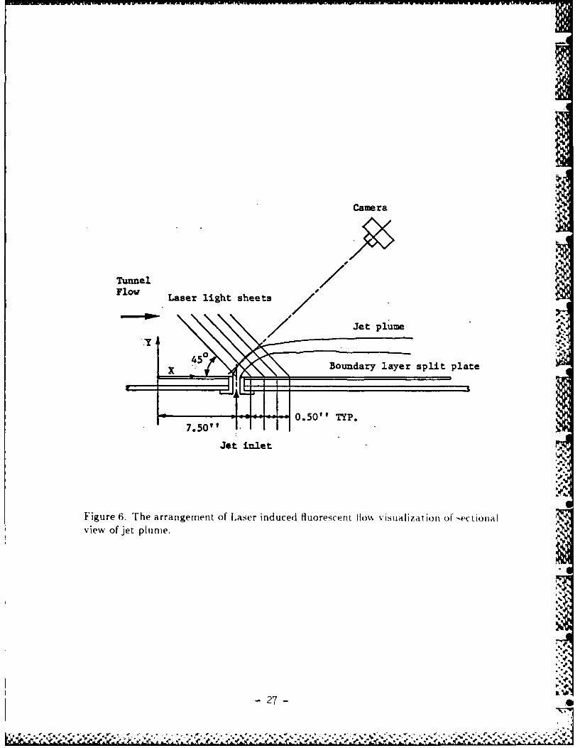
Test section dimensions are 35.6 cm high. -4.5.7 cm wide and 150 cm long (14in x 18 in x 60 in). The test section walls are made of Plexiglas for versatil-ity in observing and photographing the flow field. The experimental setup isschematically shown in Figure 6.
Two types of flow visualization techniques have been used to extract max-imum information from the flow field. The first was by using regular milk anddye technique. Dye was a mixture of alcohol. milk. and commercial food col-oring in such a way to ensure specific gravity equivalent to water. The secondtype was the laser induced fluorescence technique. Three chemicals were used:Rhodamine 6G. Rhodamine B and Fluorescein Sodium Salt. Once dissolved inwater and under the excitation of Argon-ion laser light: yellow, red and greenfluorescent colors were made visible. Dye was injected to the specific areas ofthe model at controfled rates desired for each dye exit port. Many distributedsmall dye exit ports were built into the plate and jets exit neighborhood sothe dye could be introduced at the desired points on the surface. Small dyeprobes. capable of being positioned inside the flow were also used to introducedye at regions of flow which the surface dye was not carried to.
An Argon-ion laser light souirce (I to 2 watts power) was used for thelaser fluorescence flow visualization. A 4mm cylindrical lens in front of thelaser beam produced a plane laser light sheet. Rotation of the cylindricallens results in rotation of the light sheet plane. Combined translation androtation of the light sheet plane provide visibility into the complete flow fieldat any desired orientation. Frequently the (lye for laser flow visualization wasintroduced into the jet fl|id itself. In this way became po-sib[e to observe thejet fluid deformation directly. which was not visible other\ise. On the %\holethe two flow vistialization technique, coni plemented each other for a cornpleteobservation of the details. The ge'neral arrangement of experimental -et up i--hown on Figure 6 and the coordinates ,v-tei i, -hown oi F igirre 5th.
In order to tudy different jet entrainme,,t andI interaction effect-., thetinnel velocity aid the area-averaged jet exit velocity %%a- ch-en -rich that 6*0the velocity ratio wa: I < V, A4 < 7. For each jet the major axis of jet
Or , V

- -- =W -- IR DO uvcrg
exit model was adjusted and the relative yaw angle 3 was varied to study thevortical flow interaction effects. The pulsation of jet at frequencies between1 Hz to 16 Hz were applied. An oscillating small rectangle in the wake of ajet was used to amplify the periodic vortical flow interaction effects. Variousobservations made and the resulting analysis of the flow visualization studyare discussed in the following sections.
The velocity measurement of vortical flow field was done by a three com-ponents hot-film anemometer. This system is combination of a customized TSIthree-component hot-film probe, a TSI model IFA 100 Intelligent Flow Ana-lyzer. a Scientific Solution's Lab Master 16 channels analog-to-digital converterand an IBM PC/XT compatible computer with 20 mega bytes hard disk.
The signals from three-component hot-film probe were fed into the threechannels of IFA 100 system which is connected with Lab Master A/D converter.The signals were digitized at 0.2.5 K HZ per channel and temporarily stored onthe hard disk. The laboratory computer data acquisition system is networkedwith the main computer system. VAX 11/785. through communication lines.The data were enrt to this computer for storage and latter evaluation. Thewhole data acquisition system was designed in such a way that the probe canbe calibrated io .sitij and on-line with the aid of computer. which makes theresults independent of any possible atteutiation or amplification in the processof transmitting signals from the anemometers to the computer or in the low-pass filters.
The three-component hot-film probe is illiistrated with the coordinatessystems on Figure A.7. The three films are orthogonal to each other and
parallel to the axes of Cartesian coordinate system i.r y'. z') which is defined aswire coordinate system. Let X. Y. Z be the instantaneous welocity cornponentain wire coordinate system and be parallel to axes ( '.yI. :') respectively. Theeffective cooling velocity for each wire can be written in the following formby u:.ing .Jorgenseri' decomposition relationship 1971) 2! and coordinate",\~tern relationships for rhe calibrationi of " and h .
-6-*

L-21 = k(Ol).X,2±O.5 (1±h(1))1 2 O. (j1h(0 1 )).Z 2-. (1 -h2(01 )).y.Z
u22 y 1 20 0.5 (1 +h (02 )).X 2+k ( 2)'Y±. _Z2_(1 1)/(0))- --
=ff 0.5 (i-l(0))X2 0.5 (1±h~( 3 )Y±jo)Z- J0)X
where
= tan V12 tat) -Z - V
ta tia -.- taI
-Note that k andl h are coefficients for the tang-ential and hinorial coolingo corni-
ponent.s wit 11 the defined t.arigent jal velocity c oniponwit onl the plane formed
by each hot -fil ri comnponient and probe axis and the defined niormial velocit V
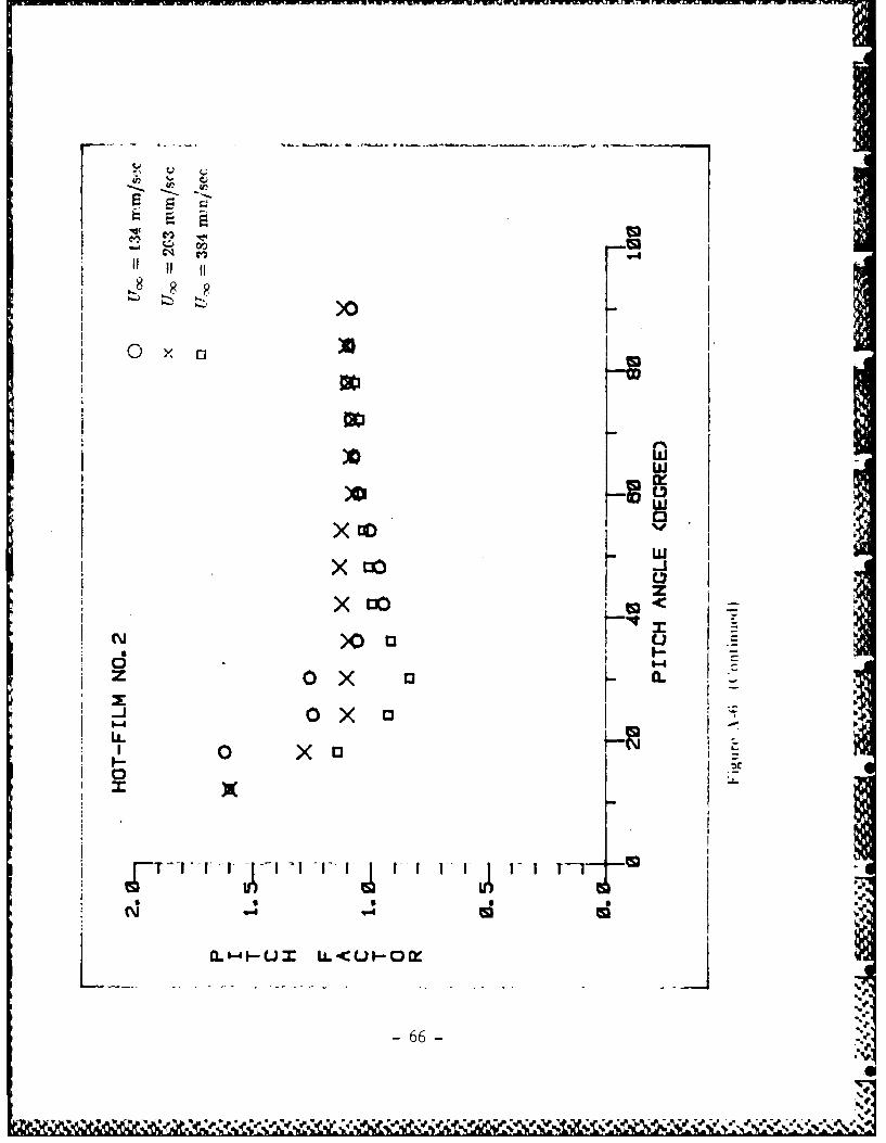
comrponent perpendicular to it. which are defined as the yaw factors and Pitch
factors. These factorsz have been obtainedl from Individual calibrations of each
hot-filni. The der aill of the calibrat iotn of three-cornporiert hot -filin proh are
discussed on Appendix A.
The %-;term of equatlins is non-linear with re ,poct to thle three unkniownl--V- V- -. These Instantaneous velocity cornponril in t he wire coordinate-
can be obtained easily-% by a -iicce--ive approximation miethod. The pre ,entapproach is fully digital with dat a acqi iit lonll~en arid hence no linearizerl 4
.were uISed. This allows t Lw yaw factor, 4- and~ pitch fact or-x b to vary % ith h 70yaw angle o and pitch angle o) re pecr vely as defirned on F i gure A. .i iHwe thli
yaw and pitch angles are riot kiiwnr 'i vpri. anl Poral IVt 11iiiriit'riraf -- hjem"l
ha, been uised to solve the ai tve e ji at n ni-
AXft er solv ing t he In rir~111W) Inu - VOcity I VCCIIIt P4t1" I X. V. Z. 11 11 witI
knowve~e of the relat ive corln;ite, roltlirioniliij hei\ "t't'T hii c)l rillt'.v.
tern r . y]. :) and w it-( (m1rib1 n(' 0 - -1011'I1 'V.X' . I ~ I -i m II md I ho -ktrT h of
Figure .S. thle ill .Tr l art~t(I- Vtlci)C vt )rMIPoriE'nl ill thot lid) ()''
diriate, -%ter can he t nind I ni rm ''i;lii \ k I, H 1ivt i ;Ir- m l!i I ow
nates:

I: co&, -.sir, 0 M 1 0 0 r _ ,__,_c= S 0 0 co.0a sina I " 6 66_
0 0 t 00 2 2 Z2 2
In above equation the rolling angle a and pitching angle are the two param-
eters which link those two coordinate systems as shown on Figure A.7 wherea is taken to be zero when wire No. I as on x' axis is in x - y plane with its
longer prongs at the smallest x values.
"I

11.Principle Observations
1. Jet Vortices
Jets in uniform cross-flow are acted on by the momentum of the cross
stream from the point of exit until complete balance and alignment between
the two flows are reached. Due to the jet bending and curvature a pressureIdgrradient is generated in planes perpendicular to the centerline of the jet flow.
The jet fluid and the entrained cross-flow form two distinct vortices (called
Prandtl's secondary flows of the first kind (1).For a symmetric jet in a
uiniform cross strea'm these two vortices are symmetrically generated with the
jet wake also being:, symmietric. Such observations have also been made in many-
studies as noted earlier.
If the jet forms, a non-svnimietric configuration wvith the cross-flow, the re-
,Uiltrig flow, field around the jet all(I inI the downstreami is highly asymmetric.
three-dimensional and usually unsteady. Various vortices are formed and their
interact ions with the wake flo%% prodluces a highly complex Hlow field. The jet
vortices. under these conditi'ons are not * %vmmnet nc and their strength are dif-
ferent. Also. the jet fluid is acted on by the nion-unliformi cross-flow miomentumi.
hience the two jet vortices follow two different trajectories. AlIl these. nt reduce-
a 'ignificantlv different flow field comnpared to the symmnetric jets.
By intreducing colored1 dye fromi approprniat e locat iorl- near the jet exit .
it wa, possible to miake the vortex core reglo)n- vilmble. The core traces akoe
correspond to their mean trajectories. A typical illustration of the miajor \,()r-
tex t rajectorie-; for itiodel I c-an be seen in Figure 7. Thik - ide viwphoto \o as
taken with mioderat clv hig-h etto free streami velocity ratio of 3.70 withI the-hurt tear drop -hape jeyetmu~l- awinga t 3 =~ M relat[i\C tO oi-
cent ng1" free -;tream. Tlhree I: tlinct mnajor vortex stemis cou ld he Idlent ifiedI inl
he above Hlow an io thle etIiefitt l Cr lit ion -. TFhe miost penet rat ed insIde jet -vortex appeared1 to h I he 1 -t reige(,t (Ane, and ii~tiallv less visible in t lie
Iuo% ti-trearit. witfh reguldar 1\(,. hif, it) -t rono etliraltniient of t he cros5 -tlew
anid g()al\ iher turbunlence lv-l. WithI the laer- fluorescence [low, vi.;i alizal-
]-A60'Sw

tion. this vortex flow became very distinct, however. Rotational sense of thesevarious vortices are discussed in Figure 10.
For small jet to free stream velocity ratios all three vortices were lyingcloser to the flat plate and less distinguishable as they were closer, weaker andnearly merged together. For small yawing angles 3 the jet-vortices representedby the upper two trajectories followed similar path and appeared to coincidefrom the side view. This was expected as the jet-vortices appeared to be almostsymmetric for decreasing yaw angle 3. For increased jet to free stream veloc-ity ratio the jet-vortices represented by the upper two trajectories penetratedfurther away into the free stream. At the mean time. it appeared that an addi-tional pair of less distinct vortices also was formed from the jet exit to join themajor (stronger) wind side jet-vortex flow. In other words, there is a possibilityof forming more major vortex systems with higher velocity asymmetric jet incross- flow.
Flow on the plate around the circular jet and the teardrop asymmetric jetis shown in Figure 8. Similar to the horse shoe vortices in front of a solid cvlin-der in cross-flow there also exist a separation region in the flow just upstreamof the various jets. For the circular jet the flow pattern is schematically shownin Figure 8a. The horse shoe vortices and the flow around the jet exit on theplate are symmetric for a symmetric jet exit. For an asymmetric jet exit withrespect to the cross-flow, the flow pattern is not symmetric even though thebasic flow physics are preserved. Surface flow pattern in the downstream of theteardrop shape jet (model 3) is shown in a top view photograph in Figure 8b.Even though the jet is issued perpendicular to the surface. the surface wake isdominated by the non-uniform entrainment hence non-symmetric. The surfaceshear stress lines, visualized by placing dye upstream on the plate around thejet. are used to help the interpretation of flow field near the flat plate surface.The flow field near the plate resenibles that of a wing at an incidence to auniform flow.
Figure 9 shows the development of jet-vortices for a teardirop .hape jet
(model 3) at various downstream distances. These photo: are taken in a plane
10-
e,-'P.oa
- ,- ,, 4. • • . • qe ...- . g ' o " " '° "I ~ " " * " " • • " " I ° , " ". *° " -% ' ' '. - - - - - - - l• 0

inclined 450 toward the oncoming flow using laser fluorescence flow visualiza-
tion technique. This figure shows how the jet fluid is deforming into the jet-vortices and demonstrates the formation of a wake-vortex near the flat platesurface.
Based on evidence described above, the explanation of how the flow de-veloped from a symmetric jet to a non-symmetric jet in cross flow is givenin Figure 10. With the aid of an imaginary plane (A), a pair of jet-vorticesand a pair of wake vortices can be seen. If the jet is symmetric, these twopair of vortices would be symmetric as schematically illustrated in Figure 10a.With a non-symmetric jet yawed to oncoming flow. on the same plane (A), thewind side jet-vortex moves away from the base plate and the lee side jet-vortexmoves closer to the plate which would result in enhancing the lee side wake-vortex and degenerating the wind side wake-vortex as shown in Figure lOb.The pair of wake vortices are the product of induced flow by the counter ro-tating jet vortices near the plate (laser-fluorescence photos have clearly shownthis wake vortices formation). Figure 10 explains the sense of rotation for thewake vortices. Note here that the shearing to the jet fluid by the cross-flow isquite different on the wind and the lee sides. This explains why there are threedistinct vortices in the flow field of Figure 7.
For a teardrop shape cross section jet positioned in the cross-flow, withthe narrow end forward (3 = 180'). the observed flow field is shown in Figure
11. Under cross-flow shearing action on the jet in a symmetrical manner thereare vortices forming around it which shed from the jet trailing end in a periodicbut symmetric manner. Figure 11 shows cross sections of jet flow developing.in parallel planes at 4.5' to the flat plate. after the jet exit into the downstream.
1.1 Unsteady Jet Vortices
The existence of periodicity in the flow behind jets in cross-flow has beenreported by many investigators before. for instance. Gordier ( .. McAllister
i related the shedding frequencies of vortices due to cross-How and a circularjet with the Struhal number based on the jet diameter. Reilly ''5 identified
1l-
- ,. ,.

two eddy groups shed periodically from different regions of the jet.
In the present non-symmetric jet study it was found that under certainflow conditions especially at higher jet to free stream velocity ratios, periodicshedding vortices were observed in the downstream of asymmetric jets in thecross flow (Figure 12). These periodic vortices were initiated on the jet windside through shearing generated at the interface between the jet flow and theuniform cross-flow.
These types of periodic vortices were observed primarily for the jet models2, 3 and 4 at relative yaw orientations of 5' to 30' to the tunnel free stream h
and with the jet to the tunnel velocity ratios of higher than three (V'/V > 3).Figure 12 shows two typical photographs of the flow containing the periodicvortices. We have labeled these as --spin-off" vortices, this terminology wasborrowed from our wing tip work (2-4), and is due to the similarities betweenthese vortices and the spin-off vortices observed there. The spin-off vorticesshared a common root, with their other ends entrained into the steady jet vor-tices. The strength. and shedding frequency of these spin-off vortices appearedto increase with the jet velocity or its velocity ratio V,/V .
Boldman et al (t7) studied two dimensional vortices shedding from a flatplate blunt trailing edge with equal and unequal velocities applied on bothsides of the plate. They found that symmetric and alternating Karman vorticesappeared in the wake with equal velocities applied as is expected. However. bydecreasing the velocity only on one side of the plate. it resulted in degeneratingthe strength on that side of vortices. And in the limit it was possible toeliminate completely that side of vortices altogether.
This analysis could be used to explain the result of present observationof the -spin-off' vortices shedding from the wind side of jet only and with thesame sense of rotation. Referring to Figure 10. one would expect a highershear on the wind side of jet surface than on the lee side. This would be moreprofound with moderately increasing the jet velocity and with a moderatelyyawing angle 3 which would provide a larger shearing surface. The shedding
-12-
$%*u ' 'V ! € ,% **** ¢ .,, , * ..

frequency appeared related to the jet velocity to the free stream velocity ratio
and the jet orientation. In the lee side of the jets certain periodicity was
present in the separated flow which was either coupled with the vortices andthe shedding frequencies or was influenced by it, since the frequency of the
wake unsteadiness and shedding were the same.
Typical common root of the spin off vortices is shown in the various figures,
we named this as the jet "wake-vortex" in the previous subsection. Both laser-
fluorescence and the regular dye indicated the jet wake-vortex was initiated
from the lee side of the jet and developed parallel to the jet vortices but closeto the flat plate. The wake-vortex was visible for moderate to higher jet flow
rates only for non-symmetric jet configurations.
When spin-off vortices were present, they appeared to roll around each
other and the wake-vortex. It should be noted here that many investigators(i8-2) have observed also similar rolling up vortices in observation of the wake
flow structure behind a cylinder with its axis perpendicular to a flat plate in
uniform cross-flow. In Taneda's observation (18). he explained that vortices
from the end of a cylinder must rotate in alternating sense and connected to
similar strength yet alternatively shedding Karman vortices behind the cylin-der. In our present observation, the wake-vortex bundled with spin-off vorticeswere always rotating in the same sense as that of the wind side jet-vortex flow.
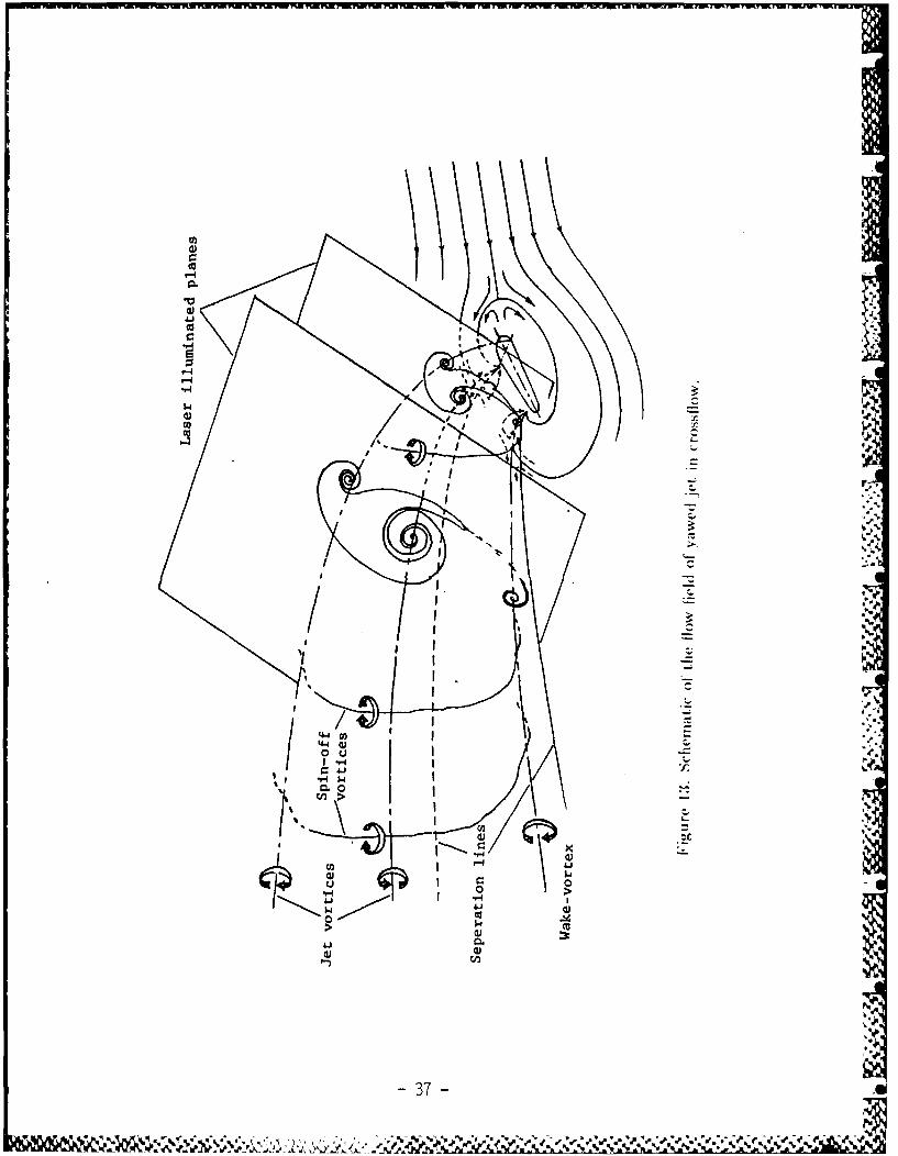
Figure 13 shows a schematic of various vortices and features of the asymmetric
jets in a uniform flow field.
To clarify the relationship between unsteadiness in the jet wake and the
spin-off vortices, artificial periodic perturbations of various frequencies were
produced on the plate in the lee side of the jets. Perturbations were created
bv oscillating in an angular manner. a cylindrical rod at the tip of which
a small flat plate fin was installed. The 6mm by 4mm rectangular fin was
positioned at the tip of the 3mm diameter rod and its presence in thf wake.
while not being rotated. did not influence the flow. As a result of the addedperiodicity. vortices similar to spin-off vortices were shed for as vmnetric jets
and for frequencies corresponding to the wake fluctuations. Figure 1 shows
-[3-
S!

two flow fields, indicating the difference due to the added perturbations.
2. Pulsating Jet
In order to investigate the effect of jet flow periodicity on the resultingflow field and especially on the various vortices in the down stream, pulsationwas applied to the jet flow. A frequency generator and a solenoid valve wereused to introduce pulsation in the jet. That is. the continuous jet was replacedby a periodically blown jet. The circular jet (model 1) and the teardrop jetshape (model 3) were subjected to variable frequency pulsations.
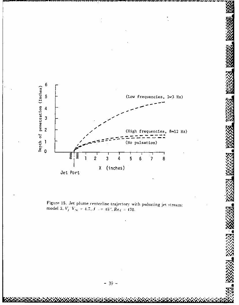
At low frequencies, 1 Hz to 4 Hz, the jet penetration into the cross-flowincreased significantly for both models 1 and 3. Vortex rings were producedby the pulsation at 1 Hz which actually impinged on the tunnel top wall. Thevortex rings were symmetric for the circular jet but they had a complicatedshape for the teardrop shape model 3. The vortex rings of this model werealso rotating around the axis of the jet along which they were moving into thecross-flow. The increased penetration of the jet is believed to be partially dueto the increased momentum in the jet pulses, since the mean flow rate wasmaintained constant.
As the frequency of the pulsation increased, gradually the flow field re-turned to the normal pattern with not much difference from that of the steadyjet including its penetration height. At low pulsation frequencies. spin-off vor-tices were not observed for the teardrop shape jet. But. they reappeared as thefrequency of pulsation increased beyond 16 Hz. A qualitative representationof the jet plume center trajectory is shown in Figure 15.
3. Swirling Jet
Two different techniques were ti,,ed to introduce swirl into the jet,. First.the flow was rotated in the plenum chamber prior to the jet exit. The rotation ofthe flow was produced using a wheel with radial spokes of rectanular form. Thewheel shaft was rotated by a variable speed motor. This created a rotational
-11-i- tl - ip
.I
,%A '

flow inside the plenum. However, the fluid exiting the jet did not appear tocontain a uniform rotational characteristic. Therefore, this technique was notvery successful. Second, a turning vane was placed inside the jet just before theexit plane. The flow following the vane would turn by itself. In both cases theturbulence level of the jets were considerably increased. This was evidencedfrom the rapid mixing of the dye in the flow and made observation difficult.Introduction of swirl in the jet was found to reduce the effective jet velocity tothe free stream velocity ratio.
The second technique, noted above, visibly produced more swirl andshowed to be more effective for the circular jet model 1. Due to the swirlin the jet, the flow of circular jet was not symmetric any more. However, itsextent of asymmetricity was not as strong as altering the jet port shape andjet flow as observed earlier. Introducing swirl in the jet should increase theentrainment of the main stream fluid into the jet (2,As a result of the in-creased entrainment, the jets were deflected rapidly toward the surface. Thisobservation is in agreement with those of the above reference. It was expectedthat part of the jet axial momentum is transformed into angular momentumwhich has little influence on the jet penetration. Experiments made on swirlingjets in cross-flow(23 ) point to opposite observations. Reduced shearing action.due to the swirl in the jet flow, across the jet which would otherwise set uppressure differential necessary to deflect the jet is discussed as the physics ofhigher penetration of the swirling jet into the cross-flow.
15-

IV. Hot-Film Measurements Results
The process of measurements with the aide of hot-film has not been corn-pleted in time for preparation of this report and especially the analysis of thelarge volume of data obtained is just beginning. Selected measurement sta-tions have been analyzed and evaluated in a preliminary level. Because ofthe fact that these data have not been fully evaluated, they represent typicalinformation which will be included in the final report for the next. contract.
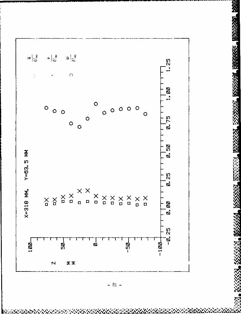
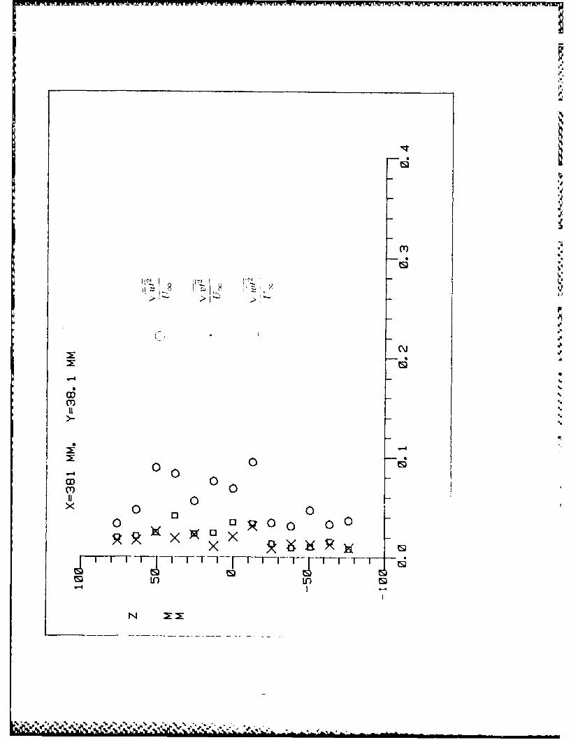
Measurements are made using the 3-D hot-film probe. in three longitudinalplane stations in the downstream of the tear drop jet exit for yaw angle 3 = 20'.In each plane, at downstream stations of 1 = .5. 10 and 1.5. traverses were madeat four heights of D = 1. 3. and 7. Mean velocity, root mean square of velocityfluctuations and cross-correlations are shown on plots in Appendix B.
Because of the analysis not being finalized, only limited discussions aremade in the following paragraphs.
Observations by McMahon et al. (6 ) have indicated that for a circular jetthe energy of periodic fluctuations is larger near the boundary of the jet plumethan at the center of the jet induced vortices. \leasurements obtained in thepresent investigation. Figure 16 for a nori-Nmiletric jet in cross-flo" arc- inagreement with the result of the reference 6. Figure 17 illustrates the effectiveblockage created by the tear drop jet at .3 = 2 y -a% angle. The flow repre,eit-sa similaritv with the wake of a solid cvliti-lrical bodv. The velocity defect callbe used as a measure of solid blockage effect, which is dtecreased as the ditancefrom the flat plate wall is increased. kt higher ,i+,.tances from the plate thedeflection of the jet due to the cross-flow redhuces the blockage and eventually.the jet fluid is aligned with the uniforni fl( % here there Ps rio wake.
1I tilee

V. Concluding Remarks
The flow field of jets in cross-flow of four different cross section geometryjets have been studied and compared with that of a circular cross section jet.The jets had equal cross section areas but different geometries. This qualita-tive study was conducted in a water tunnel for detail flow field visualization.The flow around asymmetric jets in cross-flow is of a very complex nature andcontained many features which were significantly different than that of sym-metric jets in cross flow. The flow field has been reconstructed schematicallywith flow physics discussed. F-
Periodic vortices were observed perpendicular to the cross-flow, these were
called ",pin-off" vortices. Spin-off vortices were only observed for asymmetricjets and appeared only at jet velocity to the free stream velocity ratios usuallyhigher than 2.5 or 3 and were dependent on jet port shape and orientation.
Perturbations introduced in the wake of asymmetric jets produced thespin-off vortices artificially, only when the frequency of the perturbationsmatched the separated wake flow fluctuiations. The amplitude of the natu-ral fluctuations was not sufficiently large enough to cause the vorticitv createddue to shearing between the jet and the cro,,s-flow, to shed under such situation.
A wake-vortex was observed for asvmimetric jets which was lying paralleland close to the floor plate. Once the spin-off vortices were present they becametwisted and linked near the flat plate and wrapped around the wake-vortex.
Pulsating the jet flow at low frequencies reulted in formation of vortexrings which penetrated into the main flow more than t he jet for high pulat ionfrequencies. Under this condition no spin-off vortices could be produced. Athigher pulsation freqciencie, (f > 1611:). the flow fields were similar to thatof the steady jets with incroased mixing present at the jets boundary. Intro-duction of -.wirl in the jet tio% was found to increase the jet turbulence and ,to reduce the effective jet velocity to the free stream velocity ratio.
17-
4,

There appears to be quite some similarities between jet flows and the flow,around asymmetric cylindrical bodies in uniform cross flow( 21). The presenceand the identification of these flow features is considered to be a first steptoward their full understandingutilization. enhancement or suppression of se-lected desired vortices in many fluid mechanics situations.
Quantitative results based on limited measurements indicate general trendagreements with other data for symmetric jets. For asymmetric flows of thisinvestigation the downstream flow is quite more complex as discussed in theflow visualization and highly non-symmetric.
t8I
:."
101• .5

UF r l~WL~ f~ ' W TV V YW LVW V UT OlS W V '55 VL WI W WW~ l SV -nr ItrLp
"i .
References
1. Rajaratnam, N. "Turbulent Jets." Amsterdam: New York: Elsevier Sci-entific Pub. Co., Chapter 9, pp. 184-210, 1976.
2. Wu, J. M. and A. D. Vakili. -'Wing Tip Jets Aerodynamic Performance."Proceedings of the 13th International Council for Aeronautical Science.Edited by B. Laschka and R. Staufenbiel, Seattle. Washington. August1982.
3. Wu. J. M.. A. D. Vakili and F. T. Gilliam: "Investigation on the Effects of XDiscrete Wing Tip Jets." AIAA Paper No. 83-0546. AIAA 21st AerospaceScience Meeting, Reno, Nevada, January 1983.
4. Wu. .1. M. and A. D. Vakili. "Aerodynamic Improvements by DiscreteWingtip Jets." WPAFWAL TR 84-3009. 1984.
5. WVeston. R. P.. F. C. Thames. --Properties of Aspect-Ratio-4.0 Rectangular.Jets in a Subsonic Cross Flow." AIAA Journal. Vol. 16. No. 10. pp. 701-707. October 1979.
6. McMahon. H. M., D. D. Hester. .1. G. Palfery. --Vortex Shedding Froma Turbulent Jet in a Cross Wind.- Journal of Fluid Mechanics. Vol. 48.Part 1. pp. 73-80. 1971.
7. WVu. J. C.. "Experimental and Analytical Investigat ion of .Jets Exhaisting .
Into a Deflecting Stream.- AIAA Paper No. 69-225. AIA.X/.AtS VTOLResearch. Deigi and Operation Meeting. Xtlanta. Georgia. Februar% 17-19. 1969.
8. Andreopoildes. ... --Initial Con litions. Reynold N umber Effects ant the Near Field Charac t eris tics of the [oid .Jets.; a Cross F.'low.'" .1oial of
Flight Sciences and Space Re-arcl. Vol. 8. No. 2. .larch/April 1984. pp.118- 124.
9. Crabb. I).. D. F. (. l)tiro. .1. 11. Whitelaw. "-.\ RoiI, .let Normal to aCrossflow." .Jourrial )(f -litild t, rln ,ring. Tran,;act loti. ,t the .- X1E. Vol.103. March 1981. pp. 112-153.
6 A,
_ v.
...',.

-Nv~rNV1MWV U~rKTWTV*1n FWU
10. Wu, J. Z.. 1986 a.b. Incompressible Theory of The Interaction BetweenMoving Bodies and Vorticitv Field. I. -The Production of Vorticitv byBody Surfaces and its Dissipation"'; 11. "Force Acted on Bodies by VorticityField". Acta Aerodyn. Sinica 4, No.2, 168; to appear.
11. Wu, J. Z. & Wu, CAJ. 1986. A Viscous Compressible Theory on The Inter-action Between Moving, Bodies and Flow Fields in the (.0) FrameworkSubmitted for Publication.
12. Jorgensen, F.E.. 1971. -Directional Sensitivity of Wire and Fiber-filmProbes," DISA Information No. 11, pp. 31-37. 'May.
13. Prandtl. L.. --Essentials of Fluid Dynamics, pp. 1-15- 119. Blackie &_ SonLtd.. London. 1963.
14. Gordier. R. L.. -Studies of Fluid Jets Discharging Into Moving, Liquid.~St Anthony Falls Hydro Lab., Univ. of -Minnesota. Tech. Paper No. 28Series B. 19-59.
1.5. McAllister, J. D., "~A Momentum Theory for the Effects of Crossflow onl In-compressible Turbulent Jets.** Ph.D. dissertat ion. I iversity of Tennessee.-1968.
16. Reilly. R. S.. "Investigation of the Deformation and Penetration of a Tuir-bulent Subsonic Jet Issuing Transversely into a Unifornm. Subsonic MainlStream.~ Ph.D. dissertation. University of -Maryland. 1968.
17. Boldman. D. R.. P. F-. Brinich and M. E. Goldstein. --Vortex Shedding fromia Blunt Trailing Edge with Equal and Unequal External Mean Velocitic .-Vol. 753. part 4. pp. 721 - 73-3. .J. of Fluid Mlech.. 1976.
18. Taneda. S.. -Studie on Wake V'ortices: An Experlimeral M iidy onlthe Structure of the Vo(rtex treet Behinid a Circuilar Cyliunder of FiniteILength.- Reports of Ilesearch Institute for Applied \lechanilc.;. \,(). 1. \o.41. Dec. 19-52. -
19. 5 akamoto. If.. -\rtx heddiing frorin a I?oeranular 1Pri~rii anid a i rciilar %
Cy linder Placed \vert iallv in a Tliir-bu let Mi~ Iridar\ 1,aver)* .Jnurnial ofFluid Mechanics. V'ol. 12(. p p. 117- 165. l9W. -
200
%

20. Hussain. A.K.M.F. and V. Ramjee. Periodic Wake Behind a CircularCylinder at Low Reynolds Numbers." Aero. Quarterly, Vol. 27. pp. 121-142, May, 1976.
21. Slaouti. A. and J. H.Gerrard.. .n Experimental Investigation of the EndEffects on the Wake of a Circular Cylinder Towed Through Water At LowReynolds Numbers." Journal of Fluid Mechanics. Vol. 112, pp. 297-314. V1981.
22. Simon. F.F. and J.L. Ciancone. --Flow Visualization Studv of the Ef-fect of Injection hole Geometry on an Inclined Jet in Cross Flow'".[Heat Transfer and Fluid Flow in Rotatin_ Machinery edited by: Wen-JeiYang. Hpc. 1986.
23. Pratte, B.D., and .J.F. Keefer. "Swirling Turbulent ,Jet Flows - Part 1:The Single Swirling Jet. " TME-TP-6901. LUniversity of Toronto. Toronto.Canada. 1969.
211
I
.'
i,l
,"1-
.0::

% t.

* (a) Perodic "si-f"vrie
(b onter rotating secondary vortexdue to wing tip jet. Y
Figure 2. Wake flow field with jet blowing.
- 23-

upp
ic
2.4s
F 3. o..
4-4
24.
-I
% V,
• ." -.~I% ' " . - : I
" - . . .. .•
' a
-24-.: .. ...
"..p
,z
.%%~ - ~ ~ ~ ~ %s' ' .a : hl' ,

- - Wiwv ww wrrr r
13,,
V-K
Figure 4. Non-sym metric jet in cross flow of present studv. '
-25-

0.188
0. 500
Model 1 Model 2
0. k250.1250.250 0.313
0.732 d74 2
Model 3 Model 4
.1091.710
Model 5
All dimension in inches
(a) Geometry of five jet exit models. a -
TUNNEL FLOW
(b) Coordinates and yawing angle 3.a.' %
Figure 5. Schematic of experimental arrangerment.
-26-
iZ.
Camera
Flw Laser light sheets
x Boundary layer split plate
H=-p
Figure 6. Trhe arrangemrent of Laser induced fluorescent flow% visuitlization of 'ectionalview of jet plume.
27 I

.1.7. .', 30R 0
3 A
sl.
284

J ET
f low separation area
UJJ
I-)-
(a) circular jet
Figure 8. Surface flow pattern and flow separation zonein front of jet.
%'
-29-

'IS --- 'ZZZ

(a) Inclined station: x = 7.75 in.
(b) x = 8.0 tn.
'pA 6
(c) x = 8.25 in.
SO
)x 8.75in
Fi re 9 The w'ectional view of the evolution of jet -treaa in ro ,io% )tI 1r i tic : 171i)uante at discrere do%%n.t rearn r ation : V V 2.0.
= 20 Re 2 i7f: riodel :3.
-31-
- le .. -e* ~ * .- o..

(e) x 9.
x 10.0 in
Figur 9. Contnue.
32p

'%
4 I"!(A).
i •.
.'
Counter rotating jet vortices
0 -D
Oo0 (A)
',
(b) Vertical sectioriaL ie% of as% mmet ric Jet in cro;S~flo"
~Wind side
Major shearing surface
Lee side producing "spin-off" vortices
vorex I- Degene-atede
Enhanced wake vo _/
(a) Vertical .ec t;1 o vie w of circular Jet iii c rosflo,.
!"Ii re I . Tlh, r r pariri-on t if Ut t , i .-,r, C -. V .
\ .-
33 -
%,- ~

I 's%
(Inclined station: x = 7.75 in.
-.
-4,
'.
'I.
.l
.4ma
54• °Slilll i
•-'~.ufc.wt ~ I~C~w ltW )!- ."%
riodel :g. V' il'.. 2.0. 7 H I. f2. 170.)7
- 3L4 - i0
*55 - J i i i i - I .5. . .' - -

.p
V %%

VIUIJlly 7" V-.- r~la 19ww Vmr ~m W vwv k F.
.Ile
Figue 1. Priodcal 110'(f",j*11-off' Vrlie - e (mN -,I eamof ode
3.3. 1 210
'.r 'of W.
a.
cc
020
41 0.w.
37.
V 10- V,
I -

SS
7'-
(a) Wihoth excitation.
-- 38
% % to Pil
6w
U 5 (Low frequencies, lv3 Hz)
.01.
2 '.- (High frequencies, 8,12 Hz)
'4-4
/ - = - (No pulsation)
0
1 2 3 4 5 6 7 8
X (inches)Jet Port
Figure 15. Jet plume centerline trajectory with pulsating jet stream:model ,3. V ', - 4.7.3 z- 45'". Re. 470.
-g
I
-39-.

2 21
CLCx cc
WW4J 04
x (3 0 I
P VP
131

w4w
C
0 >Uot
z CIDI
1-.4 03 D
x m
w4 d~L) 07 41 x Uv 4K
533S C) CID C
u w
L(%J
41-

Appendix A
CALIBRATION OF THREE-COMPONENT HOT-FILM ANEMOMETER
The calibration of anemometer was done by towing the hot-film probethrough water tunnel with opening top wall and sationary water at variousconstant probe speeds. The advantages for this arrangement are that the waterto probe relative velocity is measured directly and the time of calibration issufficiently short for measurement to be made above or below the ambienttemperature without any form of temperature control being required.
The calibration appratus is shown on Figure A-1. The probe to be cal-ibrated is mounted on a carriage which runs on the rails and is attached toan aluminum drive drum and an idle drum through a steel wire. This wire iswounded on both drum with two ends fixed on opposite side of the carrage.With this way any rotational movement of drive drum is immediately reflected
as longitudinal movement of the carrage. The motion is provided by a D. C.Servo motor generator with a close loop controler. The drive drum is con-nected to motor directly. The speed of carriage is selected from a potentialmeter on the motor controler for a speed range of 15 mm/sec to 570 mm/sec
The frequency at which runs can be repeated is determined by the periodrequired for the water to subside to an acceptable level, generally no more than2 minutes.
The first requirement for the calibration of three-component hot-filmanemometer is to find the characteristic constants of each hot-film compo-nent which is placed in the flow without any pitch angle or yaw angle. This isdone by the combination of pitch. yaw and roll mechanisms built on the probecarriage. With the proper arrangement of these mechanisms every hot-filmcomponent can be set perpendicular to the r.elatively on coming flow.
The calibration of this probe is on the component basis. that means eachtime we can work with one hot-film component only. The velocity range forour calibration is 1.5 mm/sec to 500 mm/sec. With the equipments mentionedin Chaper 1I. the output voltage of anemometer is digitized amid stored in thecomputer. A data reduction program was written % hich fit the anemometer
42-
4-;,Ae

output voltage V to the constant probe speed U to an expression of the form
as
V 2 = A+ BU, (Al)
where it is assuming that V is the only parameter in error. A linear regressionanalysis between t12 and U.V was done in the data rediiction program byconsidering N as a constant and being selected to give the best correlationcoefficient (i.e.. r > 10.9991 ). With this analysis the characteristics constants A.
B and N for each hot-film component were determined. The calibration curveswith anemometer output voltage versus probe speed are shown on Figure A-2.
The continuous solid line on the figure is the best fit curve of equation (A l).The characteristics constant for all three components of probe at T = 25 'C,are tabulated on Table A-1.
Table A-I. The Component Calibration Constants ,
PS.
Hot-Film Component A B N-
No. 1 -0.9823 3.4774 0.3000
No. 2 -0.6069 3., '3 148 0.3000No.., -2.0679 3.8789 0.3000
It should be noted that above tabulated calibration constants are done at
one specified fluid temperature. However. during the measurement the fluid-temperature can not be always the same as the calibration fluid temperature
Thus the effect of temperature drift on hot-film measurement hould be takeinto account. This effect was noted by Bearman (1971) for hot-wire measure-
ment in incompressible flow%. The 'imilar effect for hot-film probe meas-trementin incompressible fluid flo%% is derived as following.
Let temperatu|re of fluid be T.,. equation (Al) can be written a:
7,) A - Bf/" .12)
When temperature of fluid i- 1'. it becomes
T.,,7 )' it B t 1 .1:)
13 .... ; - .,

where Vm(T) is the measured anemometer output voltage and
A_ B _ TF - To
Al B1 TF - T
Let
To -
T.
andTF = 0 over heat ratio,
thenA _ B _0- 1 (A4
A, B, 0- I+ E or +
where a= - 1.Substituting equation (A4) into equation (A3) gives
Vm(T) 2 = 4 + + B a (.-v (As)
Now letVM(T) = V(T) + b V (A6)
where Vr.(T-) is the bridge voltage in the absence of any temperature change.Substituting equation (A6) into equation (A2). it becomes
(Ij(T) - 6V) 2 = .4 + BU v (A7)
and combining equation (A5) and (A7)
mr(T)2 - (1- rbigg)(t (T) -61) 2
and
V,,(T) = + - T). (.48)
44- .
.I6

If the change in fluid temperature are small compared with the difference be-tween hot-film temperature and fluid temperature. i.e. E/ is small. Equation(A8) becomes
Vc (T) Vm (T) 1 (B9)
This relationship gives the temperature drift correction for the measurementwhich is done at fluid temperature different from the calibration fluid temper-ature.
Above realtionships are derived with the assumption that the anemometeroutput voltage change has a linear relation with the variation of fluid temper-ature. However, it would be more practical if we can found their relationshipthrough calibration.
It was found by Saunders & Lawrence (1972) that the change in anemome-ter output with fluid temperature can be expressed with the form as
V(To) [ 2p-T(J)
where TF is hot-film operation temperature, To is the reference temperatureand T is the fluid temperature during measurement. For small temperaturevariation with respect to reference temperature T, it is adquate to rewriteequation (A2) in the form as
V'(T)_ AT -(4)
V(TI) 2(TF - To)
With above formulation, it is possible to describe the approximate temperaturedependent of a anmometer with a single constant as
M=. - (A12)2(T - To)
It should be also noted that above relation is only suitable for small tempera-ture deviation to T', and do not be confused by its form as a constant.
-45 -,

The calibration of temperature dependence was done by trying to find outthe ratio of V(T)/V(To) as function of T for a number of probe speeds. The Acalibration results of each hot-film component with five different free streamvelocities with three temperature setting are shown on Figure A-3. It can befound from these figures that the temperature gradient does not depend onfree stream velocity very much.
With the completion of the calibration of characteristics constants onequation (Al) for each hot-film and the calibration of temperature dependencerelationship, the following work need to be done is the angular characteris-tics calibration of each hot-film to find out the pitch factor and yaw factor ofit. With the completion of angular characteristics calibration, than this probeis ready for the measurement in three-dimenional flow field. The mechanismfor the measurement of three-dimensional velocity field has been explaint in
Chapter II.The method being used here for finding pitch factor and yaw factor was
suggested by Jorgensen (1971). Consider the sketch on Figure A-4. as onecomponent hot-film in a cross-flow, the effective cooling velocity acting on it 0j.
can be expresses as * -
t-2 -2 t , 2 2 (eff X + k' -Z 0111)
For a hot-film with zero yaw angle (i.e.. 0 = 0). equation (AI3) becomes
e(o) = U(0) o -- 2 r o). (.414)
For a hot-film with zero pitch angle (i.e.. o = 0). equation (A13) becomes.
[.-2ff ) .(0) 2 (COS 2 9 + hi2 0). (.415)
In above equations the parameters h and k are defined as
h pitch factor
- _ yaw factor.
Vith the calibration constants of equation ( A1) andt the aneiontnti r .ot -
put voltage, the pitch factor and yaw factor can be calculated from the following
p16 -
a 'p

1P
relations, they are derived from the combination of equations (Al), (A14) and(A 15).
h __ A____ -Cos,1 (.416)
VF V2 (- 22
k =. V2 -2( ) -Cos 2 -.j (.417)
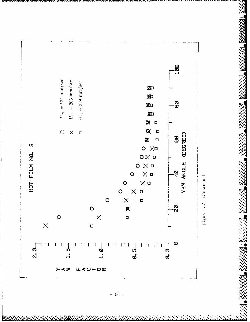
The calibration results of yaw factor and pitch factor for three hot-film corn-
ponents -are shown on Figure A-5 and Figure A-6 respectively.All of these results of yaw factor and pitch factor are tabulated on a
look-up table and stored in the computer for the measurement data reduction B
program to call-up.
References for Appendix A
Saunders L. J. and P. Lawrence (1972). "Calibration of Hot-filmAnemometers," Proceedings of the DISA Conference on Fluid Dynam-ics -Measurements in the Industrial and Medical Environments. LeicesterUniversity Press. pp. 12.5-130.
PSN.
I .47-

rwS
22
5 -0
to9anemometer
1. Motor 2. Stop switch 3. Photo-diode4. Steel wire 5. Pair of rails 6. Carriage
7. Yaw control mechanism 8. Pitch control mechanism
9. Three-component hot-film probe
Ai'r'.-I The c'aiibriii ol a1parat s tor three-cOrIIP0orwn1 pn-irllw)(w~
A

I~'I
6-4
z 0"
7'-
z> 0
I% AA*

co
-C-
0D %
C3
II I
00
HA
> -i (f)

cc
M U
Ci %we
00
pI I

clco
o U-JLL
> UiF
C'52

uj
N00
F 0~
irli
Im --i Ni
LLL
-IMb--4
II
>D 0\ 4.F-(
- 53 -

LnD
C;F-
C
CM uj
~LL
LLCM-IL
ui-N
05 -

+ N-
0 Li
(NJJ
LLiL
I
'-4
0 -1 *1 f)
I5

-F
Li)
tg0
z 0
tg -4
ILLu
0
-IM
56 --

IN,
C I.
1-4
0* 1-
-4>
dz 0~LL
LL
F-0
(> 0 - (
-57-

< - L
LIf,
'-4x
z~ OE
nL
(D Ln
> 0 -1 X(n
H5 W
&. &0.

o ~ 0LLID
Offm£F- 1 l~< 0")
fr w
wi (Lu)::CL Fmx OE 4 0
wn
C9 -
C -)
I5 -

o go
j88
LC)
F- Ox' 8z c
F-
a_-F
w x 0 X 0
'-a-LL -
IE
CD I) N1
>0~JHCN)
> 0 -J -60-
- 6o -

... .. .. ... ..... .. .. .......... .. .. . ......... .. ... ........
z 4
Figure A-4 The coordlinates defined onl each component of hot-film probe.
61 0%
%1Cpp

Cs., .fl .n l w un 3 . u n n!,r.~r'9~,,ne, v, . sr-- .- .,-' lrrX M ,pr-...r -. ~ .
cliV
COV
)J304
0f -
LL <
0 3K -.
ou
00 D
62 - %K

v-s S v ~a,. nsn -. a nn a mt .. -*-I
03X1
OWk
I reIi a II
w
z
0 X0 ox
- -63 -1
I, V
,-, Q"*
III
I "- I03 0
oxo L03
Lii
00
I~ 0 X 'OK
t.
x 0 X 13 II
0.
1-~ 4.% /% b % m.~f%* V .*~.4% .. ....

o
0)0
I e
v-I ox
w44
' 00 X
1-0 0
Q..s-1CJ LL<U-Ow
656
Oxoo
xiielw
OX a 0
0
K LLZLLU0
-66-

04 MOxoK
w
w
-1
zz
CL 0-J rXL*.. tX
-r- f '-q-,t -T
nL"I-CJ L<CJF-OM~
-67-

Probe axis(x-y plane)
,xv
v4
Probe axi
Y -ol
Fiur A.7 kthoCo-impob&n oriae ytm
on ht-fim coponets.
xp
v4
68-

Xf
12000
&10
yy z
Figure A-8. The directional relationship between coordinates(x,yz) and coordinates (x',y',z').
-69-
Appendix B
Selected results of the hot film measurements
in the down stream of the tear-drop jet model.
(For coordinates see the main text and Appendix A.)
I
-70-
- ~ .. **Se

Ur)
-4D
0 0 o
rIf
0 U.)
X XX X XXX~In DO ODa0
U.)
-71~ -

LIf)
0 0
0 U)
000
I Us)
x 0 0.0 0
Us)
a~
NN
N x x
72 -

N
00 0 0
i2
Ur)
Ur)
xx
M:
U)) U)s-4 -
11N -6
-73
1r),

In)N
Ll
In
aQ
CDoII'
~~ -C -
if i
N x
-74 -

Cr)
Il
N0
1-
x
000 0
-75 -

P~wrwrw~w7%mT~r4WrW rWN r. FkW
0 00
-4 -4II
76

4x
0 13~
?7 2

I i
x I
ir C
07
C~i75

N
0~--
o 0
0 0 S
0 00 0
0
In
Dx
ID
If)N
In) inM I -4

-4
9 El
-4
00 0 00 0-' 0 if)N
0 t
00 s
CY)
CLI
xN
x
x
IfN
-8o -
I.%
nL
E-
0s
-(\
x xX X x x xxx x
Cf)
g1 rrrr -
Us L) Uf)M
N NI3
-81 -

____ _ __ ___ ____ __ ____ ____ ___ ____ __ ____ __O
'~K~ '~KG~
v-4,
000
0)0
OD
-4 0 a-4 0xt
11.6
x~- tQ

CID,
W-WJ 022
'-4-
q E0 0 ' 4
83 -

cs*
CD lj ~
00
00 0
II I I~I ~ I
If) IOfL) s
N xx
84 -

C)T
10
co11
X
000- 0x0 00
X13Xe
-85 -

CY,
0)
OD
W4-
CY, 011S 0 0 0 000 0000
XE00000000
77'-4T 1- -4 II-- -
-86 -

0 0
000
0
LO
N 00. £
xx
'-4 4
x8

In IL
V Li)
00 0 0p
0 0
cx
In '
11 Lr)
lx
8 - %
"I 7W

Us)
vi 4
03 03E 3tCD0 0 t9
m in Lin-4
inx
89

9Z 8O 1,22
LnI~.tN
El'
0S
-4-
o00 ~ o~ooo 0
Zil
ILr
inKUN
0D0 030 03OD D 0
CD~
N I
go I.
A.5

I r I~
13 xx x
Z-r- ---z -- 1 --TT-T--r-q- - It9 -nLnt
0 0~
111
0 13 0Bx X 0 X
-T-Ln in
-A ?9 ?3 INVESTIURTIOU OF NON-SYMMETRIC JETS IN CROSS FLOWd 2/2-(DISCRETE WIN TIP JET.. (U) TENNESSEE UNIV SPRCE INSTTULLRIION J N WU ET Ri.. DEC 96 UTSI-66-13
UNCLRSSIFIED AFOSR-TR-S?-6543 RFOSR-64-9il4 F/O 28/4 Ni.
NONE
~1.0
L
1I 1.25 1.
4 l

F -4:2j
(1l
0 ta
CDm*
x 0o X 0 0 0
I I I3
V9 0

1 5
01 000030 0
-94 -I

DT4