7972 drafting ii- engineering - teachrtec.com … ii- engineering 7972 public schools of north...
TRANSCRIPT
DRAFTING II- ENGINEERING
7972
PUBLIC SCHOOLS OF NORTH CAROLINA State Board of Education | Department of Public Instruction
Career-Technical Education :: Trade & Industrial Education
Trade & Industrial EducationCareer–Technical Education
SUMMER 2005CURRICULUM GUIDE
STATE BOARD OF EDUCATION
NC DEPARTMENT OF PUBLIC INSTRUCTIONJanice O. Davis, Interim Officer301 N. Wilmington Street : : Raleigh, North Carolina 27601-2825
In compliance with federal law, NC Public Schools administers all state-operated educational programs, employment activities and admissions without discrimination because of race, religion, national or ethnic origin,color, age, military service, disability, or gender, except where exemption is appropriate and allowed by law.
Inquiries or complaints should be directed to:Dr. Elsie C. Leak, Associate Superintendent : : Office of Curriculum and School Reform Services6307 Mail Service Center : : Raleigh, NC 27699-6307 : : Telephone 919-807-3761 : : Fax 919-807-3767
Visit us on the Web:: www.ncpublicschools.org
HOWARD N. LEEChairman : : Raleigh
JANE P. NORWOODVice Chair : : Charlotte
KATHY A. TAFTGreenville
MICHELLE HOWARD-VITALWilmington
EDGAR D. MURPHYDurham
SHIRLEY E. HARRIS *Troy
MELISSA E. BARTLETT *Mooresville
ROBERT “TOM” SPEEDBoone
WAYNE MCDEVITTAsheville
JOHN TATE IIICharlotte
BEVERLY PERDUELieutenant Governor : : New Bern
RICHARD MOOREState Treasurer : : Kittrell
* not yet confirmed
i
Disclaimer Statement
Contributions of many individuals and from written resources have collectively made this curriculum guide possible. The major authors, however, do not claim or guarantee that its contents will eliminate acts of malpractice or negligence. The responsibility to adhere to safety standards and best professional practices is the duty of the practitioners, teachers, students, and /or others who apply the contents of this document.
This guide was developed with federal Carl Perkins Act funds.
2005 Career-Technical Education
North Carolina Department of Public Instruction
In compliance with federal law, including the provisions of Title IX of the Education Amendments of 1972, NC Public Schools does not discriminate on the basis of race, sex, religion, color, national or ethnic origin, age, disability, or military service in its policies, programs, activities, admissions or employment. Inquiries or complaints should be directed to the Office of Curriculum and School Reform Services, 6307 Mail Service Center, Raleigh NC 27699-6307. Telephone (919) 807-3761; Fax (919) 807-3767

ii
FOREWORD This course – Drafting – Engineering II – introduces students to the use of the graphic tools necessary to communicate, analyze, and understand the ideas and concepts found in the areas of engineering, science, and mathematics. Topics include teaming and communication skills, 3D modeling, manufacturing processes, dimensioning and conventional tolerancing, sectional views, auxiliary views, and pattern development. This course is demanding, requiring the application of complex visualization and computer skills. These skills will be used to assess, communicate, and design virtual and physical models used in science, mathematics, manufacturing, transportation, and structural systems. This guide has been developed to help teachers offer a focused, demanding and exciting program of study addressing the advanced concepts and principles of engineering graphics. Included are specific learning objectives, evaluation tools, recommended activities, equipment list, facility specifications, a bibliography of reference media, and the names and addresses of media vendors. It is our goal to provide the children of our state education of the highest quality. As this guide reflects our goal of continuous improvement, we encourage you to communicate to us ways to improve the material within this publication. Your suggestions will be welcomed and appreciated.

iii
TABLE OF CONTENTS
Page SECTION I
Foreword . . . . . . . . . ii
Acknowledgments . . . . . . . . iv
Using the Curriculum Materials . . . . . . v
Course Blueprint . . . . . . . . viii
SECTION II – UNITS OF INSTRUCTION
Unit A Leadership Development . . . . . 1
Unit B 3D Modeling . . . . . . . 4
Unit C Manufacturing Processes . . . . 14 Unit D Dimensioning and Conventional Tolerancing . . 29
Unit E Sectional Views . . . . . . 43 Unit F Auxiliary Views . . . . . . 55 Unit G Pattern Development . . . . . . 63
SECTION III - APPENDICES
A. Bibliography / References . . . . . . 68
B. Vendor's Addresses for Texts, Videos, Literature, and Software . 69
C. Equipment List . . . . . . . 71 D. Facility Design Specifications for Drafting Program . . . 72
E. Curriculum Products Evaluation Form . . . . 74
iv
ACKNOWLEDGMENTS The Division of Instructional and Accountability Services and the Trade and Industrial Education staff wish to give special thanks to the individuals who spent many hours revising the Drafting Engineering II curriculum and test-item banks. The process included a review of international literature, review of suggestions offered by teachers and administrators from throughout the state, and many hours spent in constructive discussion and development. The following individuals developed the Summer 2005 Drafting Engineering II blueprint, curriculum guide and classroom and secure test-item banks: Ted Branoff Team Leader, Associate Professor NCSU David Lambert Drafting Teacher Northwest Guilford High School Ansel Slagle Drafting Teacher NCSU Amber Thompson Drafting Teacher Isothermal Community College Sonny Tomberlin Drafting Teacher Union County Career Center Patty Weavil Drafting Teacher South Rowan High School We would like to extend our gratitude and thanks to those who have contributed their time and effort to previous versions of the Drafting Engineering Curriculum. We appreciate their hard work. Finally, we would like to thank the teachers, directors, and others who have taken their time to critique our progress and offer suggestions during this process. Our work is better for their effort. Tom Shown Consultant, Trade and Industrial Education, NCDPI Rebecca Payne Section Chief, Industrial Technology and Human Services, NCDPI
Wandra Polk Director of Secondary Education, NCDPI
v
USING THE CURRICULUM MATERIALS
Purpose
The Drafting – Engineering II Curriculum Guide was developed as a resource for teachers to use in planning and implementing a competency-based instructional management drafting program in their school. These materials are tools used in the curriculum management process.
Curriculum Guide Description
Drafting – Engineering II was designed to be a one unit course (135-180 hours of instruction). This course introduces students to the use of the graphics tools necessary to communicate, analyze, and understand the ideas and concepts found in the areas of engineering, science, and mathematics. Topics include teaming and communication skills, 3D modeling, manufacturing processes, dimensioning and conventional tolerancing, sectional views, auxiliary views, and pattern development. Skills in communication, mathematics, science, leadership, teamwork, and problem-solving are reinforced in this course. Hands-on work experience and Skills-USA leadership activities provide many opportunities to enhance classroom instruction and career development.
General Instruction
Drafting – Engineering II may be taught using individualized, whole class, or small team strategies or a combination of each. Regardless of the method used, it is essential that the activities reflect the competencies and objectives of this course.
The course demands much from the student and teacher in terms of its complexity and the brevity of time in which the materials are to be mastered. Because of time limitations and the amount of material to be covered, one cannot teach objectives as discrete units of instruction. Objectives must be taught concurrently within the larger context of activities. This allows for the efficient use of time as well as reflecting good pedagogy.
Blueprint
The blueprint (See the Drafting – Engineering II Blueprint on the following pages) lists the competencies the student is to achieve. Competencies are mastered when a student masters the objectives which make up the competency. Course weight is the degree of importance given to each objective in relation to the entire course of study. This in turn will determine the number of test-items per objective on any test developed by the state department. For example, on a state EOC 100 item assessment, a cognitive objective having a value of 10% will have 10 test-items representing that objective.
vi
Units of Instruction
The Units of Instruction section is designed to give the teacher detailed information directly correlated to the blueprint and test-item bank. It attempts to explain in more detail what information or behavior the student is expected to know or do. Unless a student has an individualized education plan, he/she will be expected to become competent in all areas covered within this course at the end of 135-180 hours of instruction.
Leadership Development Unit
Objective 1.01 covers material on preparing and delivering a technical presentation. This section is useful for all students who will have to present material or give a talk in front of a group. It is particularly useful to those teachers and students who participate in SkillsUSA-VICA. Objective 1.02 covers information on team building skills.
3D Modeling Unit
Although this section can be completed using the 3D modeling capabilities of AutoCAD®, it is strongly recommended that the teacher use a constraint-based modeling software such as Inventor®, ProDesktop®, SolidWorks®, or SolidEdge®. Objective 2.01 builds on the 3D modeling activities in Drafting I by covering techniques for creating 3D geometry. Objective 2.02 presents techniques for modifying and duplicating 3D geometry. Objective 2.03 is a performance activity requiring students to produce a 3D model. A rubric is included for the performance assessment.
Manufacturing Processes Unit
Objective 3.01 introduces students to the concepts and terminology found in manufacturing. Objective 3.02 covers the types of notation that are necessary on engineering drawings to describe particular manufacturing processes. Objective 3.03 is a performance activity requiring students to construct drawings and apply notations that best describe the processes used to manufacture the object. A rubric is included for the performance assessment.
Dimensioning and Conventional Tolerancing Unit In Objective 4.01, students are introduced to intermediate dimensioning techniques. Objective 4.02 presents procedures for determining tolerance dimensions. Objective 4.03 requires students to construct three drawings and correctly apply dimensions to them, including tolerance dimensions. A rubric is included for the performance assessment.
Sectional Views Unit
Objective 5.01 covers the concepts and principles of sectional views. Included are the types of sectional views and the conventional practices that are followed for these types of drawings. In Objective 5.02 is a performance activity requiring students to complete a multiview drawing with a sectional view. A rubric is included for the performance assessment.
Auxiliary Views Unit
In Objective 6.01, students are presented with the concepts and principles of auxiliary views. Objective 6.02 requires students to correctly construct a multiview drawing with the required auxiliary view to describe the size and shape of the object. A rubric is included for the performance assessment.
Pattern Development Unit
Objective 7.01 introduces students to the techniques necessary to construct pattern developments for things such as car bodies, packaging, and other objects formed from flat materials. Objective 7.02
vii
requires students to create two pattern developments. A rubric is included for the performance assessment.
Bibliography/References (Appendix A)
This section provides the texts’ author(s), name of the texts, and publishers of the texts listed within the Units of Instruction section.
Vendor’s Addresses for Texts, Literature, and Film (Appendix B)
We have included a partial listing of where and who to contact for obtaining texts, literature, software, and videos.
Equipment List (Appendix C)
The equipment list (updated as of this printing, June 2005), gives the minimum number of tools, equipment, and software necessary for the instruction of Drafting – Engineering II.
Facility Design Specifications for Drafting Program (Appendix D)
These are updated facility design specifications for a drafting program.
Drafting – Engineering II Curriculum Products Evaluation Form (Appendix E)
Included in this guide is an evaluation form. We sincerely want your thoughtful suggestions for improving the curriculum products. Many of the improvements within this guide and the test-item bank is the result of teachers who have taken the time to make suggestions for improvement. Please take the time to respond to us on ways to improve our work.
Final Comment
If you have any questions regarding any aspect of this course, curriculum guide, test-item bank, equipment, literature, or software needs, please call or write Tom Shown 919.807.3880, [email protected].
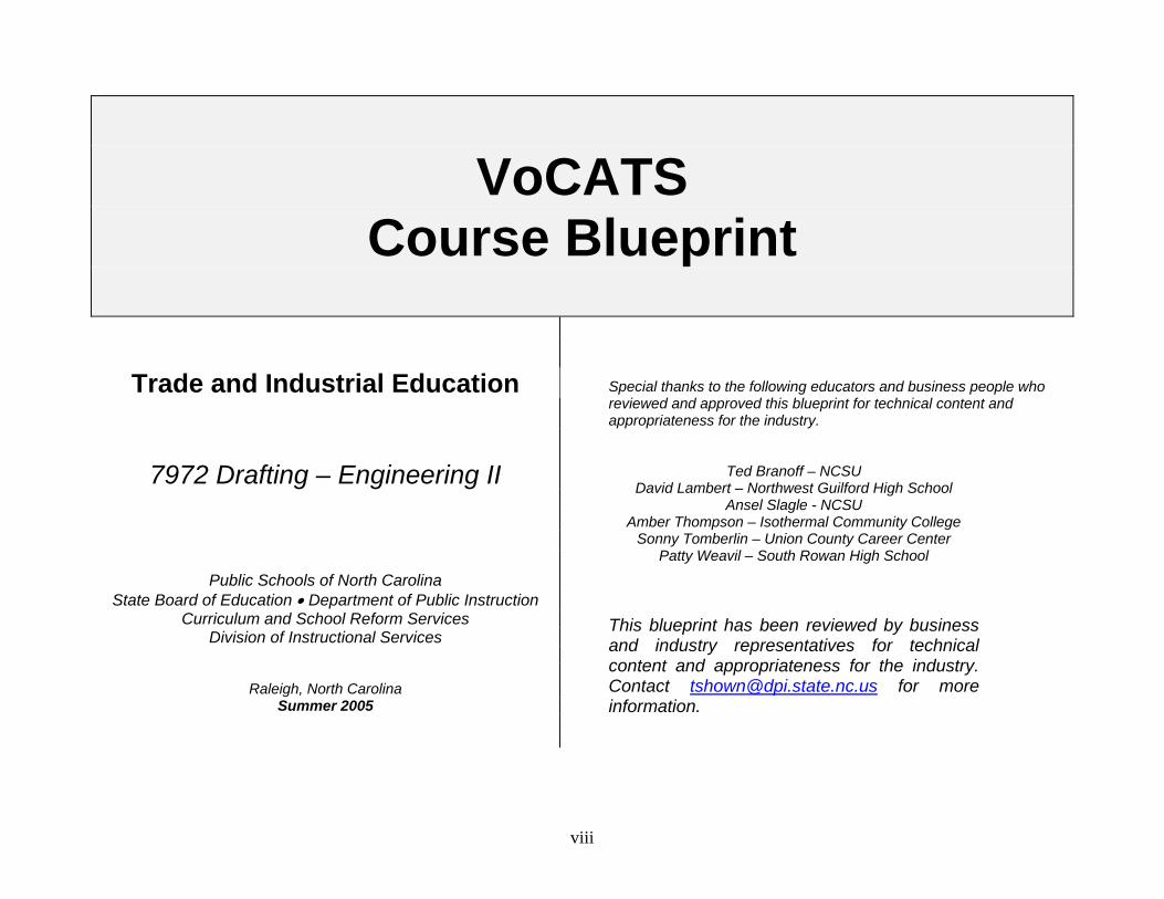
VoCATS
Course Blueprint
Trade and Industrial Education
7972 Drafting – Engineering II
Public Schools of North Carolina State Board of Education • Department of Public Instruction
Curriculum and School Reform Services Division of Instructional Services
Raleigh, North Carolina Summer 2005
Special thanks to the following educators and business people who reviewed and approved this blueprint for technical content and appropriateness for the industry.
Ted Branoff – NCSU David Lambert – Northwest Guilford High School
Ansel Slagle - NCSU Amber Thompson – Isothermal Community College
Sonny Tomberlin – Union County Career Center Patty Weavil – South Rowan High School
This blueprint has been reviewed by business and industry representatives for technical content and appropriateness for the industry. Contact [email protected] for more information.
viii
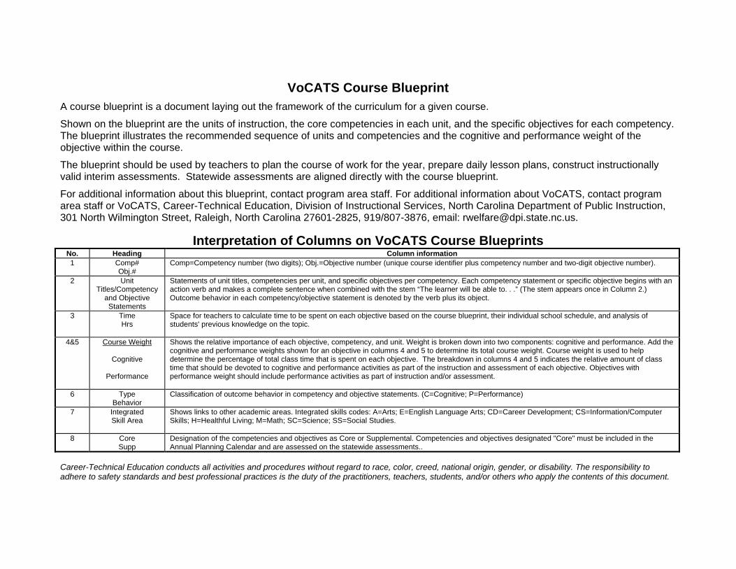
VoCATS Course Blueprint A course blueprint is a document laying out the framework of the curriculum for a given course.
Shown on the blueprint are the units of instruction, the core competencies in each unit, and the specific objectives for each competency. The blueprint illustrates the recommended sequence of units and competencies and the cognitive and performance weight of the objective within the course.
The blueprint should be used by teachers to plan the course of work for the year, prepare daily lesson plans, construct instructionally valid interim assessments. Statewide assessments are aligned directly with the course blueprint.
For additional information about this blueprint, contact program area staff. For additional information about VoCATS, contact program area staff or VoCATS, Career-Technical Education, Division of Instructional Services, North Carolina Department of Public Instruction, 301 North Wilmington Street, Raleigh, North Carolina 27601-2825, 919/807-3876, email: [email protected].
Interpretation of Columns on VoCATS Course Blueprints No. Heading Column information 1 Comp#
Obj.# Comp=Competency number (two digits); Obj.=Objective number (unique course identifier plus competency number and two-digit objective number).
2 UnitTitles/Competency
and Objective Statements
Statements of unit titles, competencies per unit, and specific objectives per competency. Each competency statement or specific objective begins with an action verb and makes a complete sentence when combined with the stem “The learner will be able to. . .” (The stem appears once in Column 2.) Outcome behavior in each competency/objective statement is denoted by the verb plus its object.
3 TimeHrs
Space for teachers to calculate time to be spent on each objective based on the course blueprint, their individual school schedule, and analysis of students' previous knowledge on the topic.
4&5 Course Weight
Cognitive
Performance
Shows the relative importance of each objective, competency, and unit. Weight is broken down into two components: cognitive and performance. Add the cognitive and performance weights shown for an objective in columns 4 and 5 to determine its total course weight. Course weight is used to help determine the percentage of total class time that is spent on each objective. The breakdown in columns 4 and 5 indicates the relative amount of class time that should be devoted to cognitive and performance activities as part of the instruction and assessment of each objective. Objectives with performance weight should include performance activities as part of instruction and/or assessment.
6 TypeBehavior
Classification of outcome behavior in competency and objective statements. (C=Cognitive; P=Performance)
7 IntegratedSkill Area
Shows links to other academic areas. Integrated skills codes: A=Arts; E=English Language Arts; CD=Career Development; CS=Information/Computer Skills; H=Healthful Living; M=Math; SC=Science; SS=Social Studies.
8 CoreSupp
Designation of the competencies and objectives as Core or Supplemental. Competencies and objectives designated "Core" must be included in the Annual Planning Calendar and are assessed on the statewide assessments..
Career-Technical Education conducts all activities and procedures without regard to race, color, creed, national origin, gender, or disability. The responsibility to adhere to safety standards and best professional practices is the duty of the practitioners, teachers, students, and/or others who apply the contents of this document.

TRADE AND INDUSTRIAL EDUCATION COURSE BLUEPRINT for: 7972 ENGINEERING II
(Recommended hours of instruction: 135-180 hours)
Course Weight Comp # Obj #
Unit Titles/Competency and Objective Statements (The Student will be able to:)
Time Hours
Cognitive Performance
Type Behavior
Integrated Skill Area
Core Supp
1 2 3 54 6 7 8 100% Total Course Weight 51% 49%
A LEADERSHIP D401.00 Demonstrate communication, problem solving, and team building skills. 1% 2% C3P C CoreD401.01 Demonstrate communication skills 1% 1% C3P C CoreD401.02 Demonstrate problem solving and team building skills. 1% C3P C Core
B 3D MODELING D402.00 Demonstrate 3D solid modeling techniques. 10% 10% Core D402.01 Explain techniques for creating 3D geometry. 7% C3 Core D402.02 Explain techniques for modifying and duplicating 3D geometry. 3% C3 Core D402.03 Construct a 3D solid model. 10% C3P Core
Course Weight Comp #
Obj #
Unit Titles/Competency and Objective Statements (The Student will be able to:)
Time Hours
Cognitive Performance Type
Behavior Integrated Skill Area
Core Supp
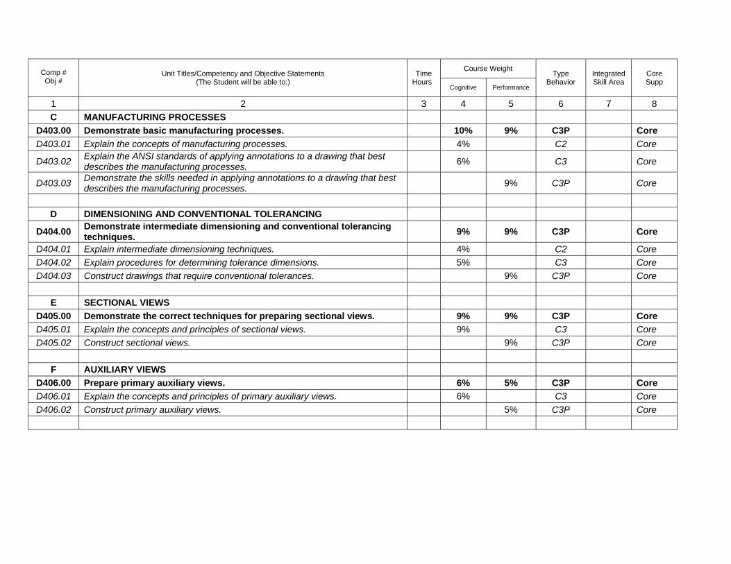
1 2 3 54 6 7 8C MANUFACTURING PROCESSES
D403.00 Demonstrate basic manufacturing processes. 10% 9% C3P Core D403.01 Explain the concepts of manufacturing processes. 4% C2 Core
D403.02 Explain the ANSI standards of applying annotations to a drawing that best describes the manufacturing processes. 6% C3 Core
D403.03 Demonstrate the skills needed in applying annotations to a drawing that best describes the manufacturing processes. 9% C3P Core
D DIMENSIONING AND CONVENTIONAL TOLERANCING
D404.00 Demonstrate intermediate dimensioning and conventional tolerancing techniques. 9% 9% C3P Core
D404.01 Explain intermediate dimensioning techniques. 4% C2 Core D404.02 Explain procedures for determining tolerance dimensions. 5% C3 Core D404.03 Construct drawings that require conventional tolerances. 9% C3P Core
E SECTIONAL VIEWS
D405.00 Demonstrate the correct techniques for preparing sectional views. 9% 9% C3P Core D405.01 Explain the concepts and principles of sectional views. 9% C3 Core D405.02 Construct sectional views. 9% C3P Core
F AUXILIARY VIEWS
D406.00 Prepare primary auxiliary views. 6% 5% C3P Core D406.01 Explain the concepts and principles of primary auxiliary views. 6% C3 Core D406.02 Construct primary auxiliary views. 5% C3P Core
Course Weight Comp #
Obj #
Unit Titles/Competency and Objective Statements (The Student will be able to:)
Time Hours
Cognitive Performance Type
Behavior Integrated Skill Area
Core Supp
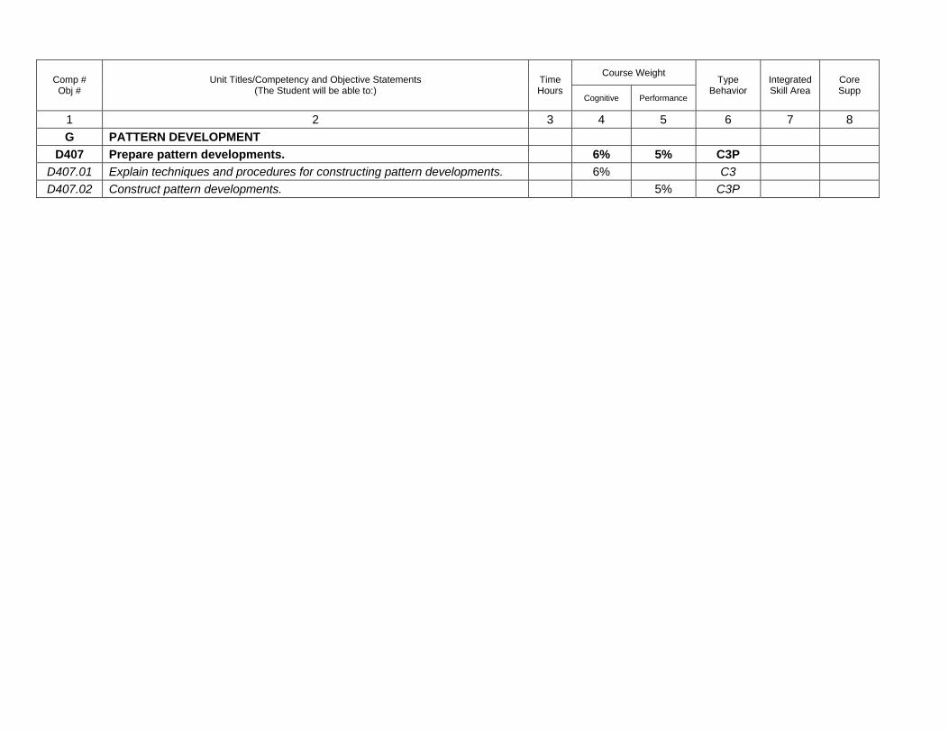
1 2 3 54 6 7 8G PATTERN DEVELOPMENT
D407 Prepare pattern developments. 6% 5% C3PD407.01 Explain techniques and procedures for constructing pattern developments. 6% C3 D407.02 Construct pattern developments. 5% C3P

Engineering II Summer 2005
Leadership Development 001. Demonstrate communication, problem solving, and team building skills 001.01 Demonstrate communication skills 001.02 Demonstrate problem solving and team building skills
1
Engineering II Summer 2005
UNIT A: Leadership
Competency: D401.00 Demonstrate communication, problem solving, and team building skills
Objective: D401.01 Demonstrate communication skills Introduction: The purpose of this unit is to develop leadership skills focusing on communication strategy. (Reference: T&I Leadership Teacher Guide)
Explain the following: A. Please see the questions written in your classroom test-item bank. These will reflect the
content to be covered.
B. For more detailed information, use your T&I Leadership Teacher Guide: Level II, Communication Skills
2

Engineering II Summer 2005
UNIT A: Leadership
Competency: D401.00 Demonstrate communication, problem solving, and team building skills
Objective: D401.02 Demonstrate problem solving and team building skills Introduction: The purpose of this unit is to develop leadership skills focusing on problem solving and team building. (Reference: T&I Leadership Teacher Guide)
Explain the following: A. Please see the questions written in your classroom test-item bank. These will reflect the
content to be covered.
B. For more detailed information, use your T&I Leadership Teacher Guide: Level II, Team Building Skills.
3
Engineering II Summer 2005
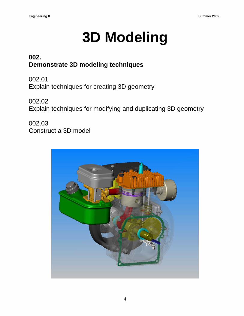
3D Modeling 002. Demonstrate 3D modeling techniques 002.01 Explain techniques for creating 3D geometry 002.02 Explain techniques for modifying and duplicating 3D geometry 002.03 Construct a 3D model
4
Engineering II Summer 2005
UNIT B: 3D Modeling
Competency: D402.00 Demonstrate 3D solid modeling techniques.
Objective: D402.01 Explain techniques for creating 3D geometry. Introduction: The purpose of this unit is to build on the 3D CAD concepts and commands that were learned in Drafting I. When covering the 3D CAD material, it is recommended that one of the following constraint-based CAD programs be used: Inventor®, ProDesktop®, SolidWorks®, or SolidEdge®. Although it is possible to use AutoCAD® (not AutoCAD® LT) for most of the concepts, engineering firms that do serious 3D part modeling are using constraint-based or parametric modelers.
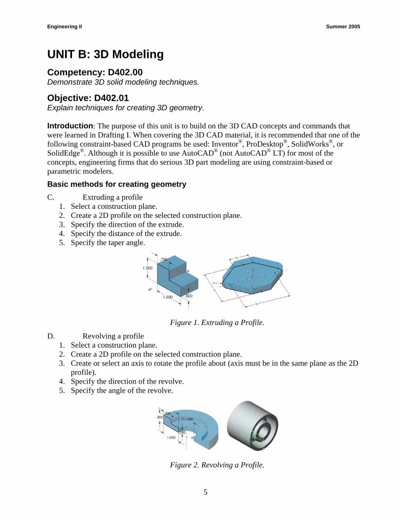
Basic methods for creating geometry C. Extruding a profile
1. Select a construction plane. 2. Create a 2D profile on the selected construction plane. 3. Specify the direction of the extrude. 4. Specify the distance of the extrude. 5. Specify the taper angle.
Figure 1. Extruding a Profile.
D. Revolving a profile 1. Select a construction plane. 2. Create a 2D profile on the selected construction plane. 3. Create or select an axis to rotate the profile about (axis must be in the same plane as the 2D
profile). 4. Specify the direction of the revolve. 5. Specify the angle of the revolve.
Figure 2. Revolving a Profile.
5
Engineering II Summer 2005
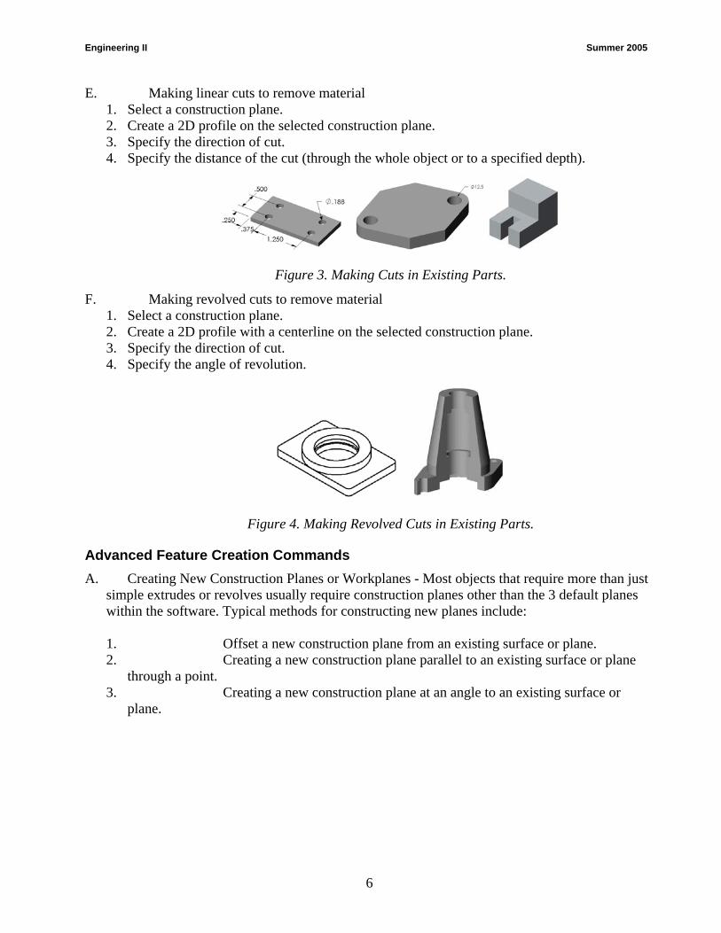
E. Making linear cuts to remove material 1. Select a construction plane. 2. Create a 2D profile on the selected construction plane. 3. Specify the direction of cut. 4. Specify the distance of the cut (through the whole object or to a specified depth).
Figure 3. Making Cuts in Existing Parts.
F. Making revolved cuts to remove material 1. Select a construction plane. 2. Create a 2D profile with a centerline on the selected construction plane. 3. Specify the direction of cut. 4. Specify the angle of revolution.
Figure 4. Making Revolved Cuts in Existing Parts.
Advanced Feature Creation Commands A. Creating New Construction Planes or Workplanes - Most objects that require more than just
simple extrudes or revolves usually require construction planes other than the 3 default planes within the software. Typical methods for constructing new planes include:
1. Offset a new construction plane from an existing surface or plane. 2. Creating a new construction plane parallel to an existing surface or plane
through a point. 3. Creating a new construction plane at an angle to an existing surface or
plane.
6
Engineering II Summer 2005
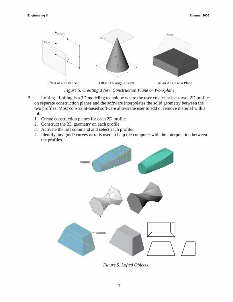
Offset at a Distance Offset Through a Point At an Angle to a Plane
Figure 5. Creating a New Construction Plane or Workplane
B. Lofting - Lofting is a 3D modeling technique where the user creates at least two, 2D profiles on separate construction planes and the software interpolates the solid geometry between the two profiles. Most constraint-based software allows the user to add or remove material with a loft. 1. Create construction planes for each 2D profile. 2. Construct the 2D geometry on each profile. 3. Activate the loft command and select each profile. 4. Identify any guide curves or rails used to help the computer with the interpolation between
the profiles.
Figure 5. Lofted Objects.
7

Engineering II Summer 2005
C. Sweeps - Sweeps are typically defined by a profile and a path. The profile determines the cross-section of the sweep and the path defines the direction of the sweep. As with the loft, most constraint-based software allows the user to add or remove material with a sweep. 1. Create a sketch to define the path of the sweep. 2. Create a sketch to define the profile of the sweep. Make sure the profile and the path
intersect. 3. Activate the sweep command and select the profile and the path.
Figure 6. Swept Objects.
8
Engineering II Summer 2005
UNIT B: 3D Modeling
Competency: D402.00 Demonstrate 3D solid modeling techniques.
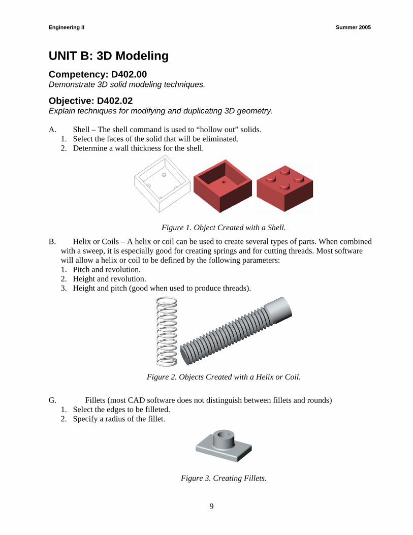
Objective: D402.02 Explain techniques for modifying and duplicating 3D geometry. A. Shell – The shell command is used to “hollow out” solids.
1. Select the faces of the solid that will be eliminated. 2. Determine a wall thickness for the shell.
Figure 1. Object Created with a Shell.
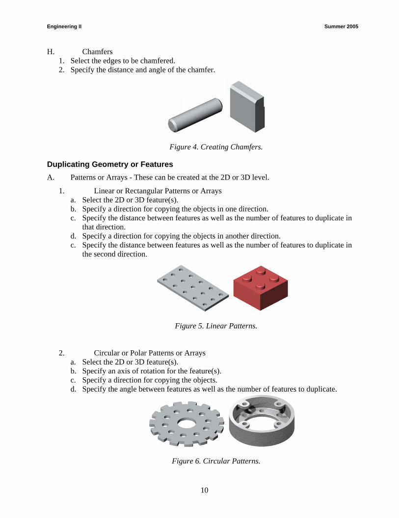
B. Helix or Coils – A helix or coil can be used to create several types of parts. When combined with a sweep, it is especially good for creating springs and for cutting threads. Most software will allow a helix or coil to be defined by the following parameters: 1. Pitch and revolution. 2. Height and revolution. 3. Height and pitch (good when used to produce threads).
Figure 2. Objects Created with a Helix or Coil.
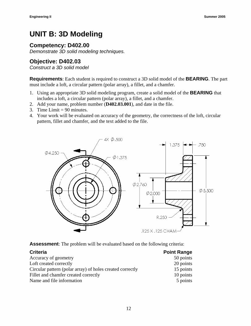
G. Fillets (most CAD software does not distinguish between fillets and rounds)
1. Select the edges to be filleted. 2. Specify a radius of the fillet.
Figure 3. Creating Fillets.
9
Engineering II Summer 2005
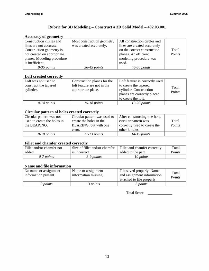
H. Chamfers 1. Select the edges to be chamfered. 2. Specify the distance and angle of the chamfer.
Figure 4. Creating Chamfers.
Duplicating Geometry or Features A. Patterns or Arrays - These can be created at the 2D or 3D level.
1. Linear or Rectangular Patterns or Arrays a. Select the 2D or 3D feature(s). b. Specify a direction for copying the objects in one direction. c. Specify the distance between features as well as the number of features to duplicate in
that direction. d. Specify a direction for copying the objects in another direction. c. Specify the distance between features as well as the number of features to duplicate in
the second direction.
Figure 5. Linear Patterns.
2. Circular or Polar Patterns or Arrays a. Select the 2D or 3D feature(s). b. Specify an axis of rotation for the feature(s). c. Specify a direction for copying the objects. d. Specify the angle between features as well as the number of features to duplicate.
Figure 6. Circular Patterns.
10

Engineering II Summer 2005
B. Mirroring 3D Features a. Select the 3D feature(s). b. Specify a 2D plane to mirror the features about.
Figure 7. Mirroring 3D Features.
11
Engineering II Summer 2005
UNIT B: 3D Modeling
Competency: D402.00 Demonstrate 3D solid modeling techniques.
Objective: D402.03 Construct a 3D solid model Requirements: Each student is required to construct a 3D solid model of the BEARING. The part must include a loft, a circular pattern (polar array), a fillet, and a chamfer.
1. Using an appropriate 3D solid modeling program, create a solid model of the BEARING that includes a loft, a circular pattern (polar array), a fillet, and a chamfer.
2. Add your name, problem number (D402.03.001), and date in the file. 3. Time Limit = 90 minutes. 4. Your work will be evaluated on accuracy of the geometry, the correctness of the loft, circular
pattern, fillet and chamfer, and the text added to the file.
Assessment: The problem will be evaluated based on the following criteria:
Criteria Point Range Accuracy of geometry 50 points Loft created correctly 20 points Circular pattern (polar array) of holes created correctly 15 points Fillet and chamfer created correctly 10 points Name and file information 5 points
12
Engineering II Summer 2005
Rubric for 3D Modeling – Construct a 3D Solid Model – 402.03.001 Accuracy of geometry Construction circles and lines are not accurate. Construction geometry is not created on appropriate planes. Modeling procedure is inefficient.
Most construction geometry was created accurately.
All construction circles and lines are created accurately on the correct construction planes. An efficient modeling procedure was used.
Total Points
0-35 points 36-45 points 46-50 points Loft created correctly Loft was not used to construct the tapered cylinder.
Construction planes for the loft feature are not in the appropriate place.
Loft feature is correctly used to create the tapered cylinder. Construction planes are correctly placed to create the loft.
Total Points
0-14 points 15-18 points 19-20 points Circular pattern of holes created correctly Circular pattern was not used to create the holes in the BEARING.
Circular pattern was used to create the holes in the BEARING, but with one error.
After constructing one hole, circular pattern was correctly used to create the other 3 holes.
Total Points
0-10 points 11-13 points 14-15 points Fillet and chamfer created correctly Fillet and/or chamfer not added.
Size of fillet and/or chamfer is incorrect.
Fillet and chamfer correctly added to the part.
Total Points
0-7 points 8-9 points 10 points Name and file information No name or assignment information present.
Name or assignment information missing.
File saved properly. Name and assignment information attached to file properly.
Total Points
0 points 3 points 5 points Total Score
13

Engineering II Summer 2005
Manufacturing Processes 003. Demonstrate basic concepts of manufacturing processes 003.01 Explain the concepts of manufacturing processes 003.02 Explain the ANSI standards of applying annotations to a drawing that best describes the manufacturing process 003.03 Demonstrate the skills needed in applying annotations to a drawing that best describes the manufacturing process
14
Engineering II Summer 2005
UNIT C: Manufacturing Processes Competency: D403.00 Demonstrate basic concepts of manufacturing processes. Objective: D403.01 Explain the concepts of manufacturing processes. Introduction: Before preparing a drawing for the production of a part, the drafter/designer must consider what manufacturing processes are to be used. These processes will determine the representation of the detailed features, choice of dimensions, and machining accuracy. The purpose of this unit is to provide the student with information about terms and processes used in manufacturing that will assist them with the skills needed to development mechanical drawings for industry. Manufacturing: R1 (271) A. The word manufacturing is derived from the Latin “manu factus”, meaning “made by hand”.
Modern meaning of the word manufacturing is the process of converting raw materials into products.
B. The manufacturing process involves three important phases: 1) product design, 2) selection of materials, and 3) the selection of various manufacturing production methods and techniques.
C. Any number of process methods may be used by industry. For this reason, the designer and the drafter must have a working knowledge of the various processes that could produce a part in order to lower cost and reduce production time.
D. The information needed to produce a part in a manufacturing department, most often comes in the form of a working drawing.
Manufacturing Processes: R1 (281), R3 (226), R4 (293) A. In the actual processing of a part consists of three main stages: 1) Rough forming, 2)
Finishing, and 3) Assembly. B. Rough Forming – consist of shaping the part by casting, forging, and welding.
1. Casting a. Sand Casting is made by pouring molten metal into a cavity in damp sand.
Once it cools and is removed from the mold the part is then machined. b. Die Castings are formed by forcing molten metal into cavities between
metal dies. i. This process is much faster than sand casting and is used where rapid
production is used. ii. It also requires little or no machining.
2. Forging a. Drop forging is produced by hammering heated bars of metal between dies. b. Press forging is produced by applied by a slowly squeezing action.
15
Engineering II Summer 2005
c. Advantage of forgings over castings is that forgings are much stronger. 3. Welding
a. The process of fusion or joining of two pieces of metal by means of heat. b. Usually a part is built up from cut stock forms, assembled, and welded
together. C. Finishing – is largely done in the machine shop to finish sizing holes and surfaces.
1. Machining a. Machining might require the use of a grinding machine, lathe, milling
machine, and or drill press b. The above machines will allow the machinist to: turn, bore, ream, mill, and
grind a part to a specific size and shape. 2. Finishing might include: polishing, burnishing, deburring, surface treating, coating, and
plating. D. Assembly – various parts are put together to complete the product. This may require
additional machining however this retooling costs money and downtime. Manufacturers look to their company designers and engineers to keep manufacturing cost in check. One way of accomplishing this is to produce 3D solid models using CAD software that allows designers and engineers to update and modify their assembly drawings to fit changing criteria.
Manufacturing Materials: R1 (279), R4 (287) A. There is a wide variety of materials available for production manufacturing that fall into
three general categories: metal, plastic, and inorganic materials. B. Metals are classified as ferrous, nonferrous, and alloys.
1. Ferrous metals contain iron, and steel. 2. Nonferrous metals do not have iron content, such as copper and aluminum for examples. 3. Alloys are a mixture of two or more metals.
C. Inorganic materials include carbon, ceramics, and composites. 1. Carbon and graphite or classified together and have low tensile strength (ability to be
stretched). 2. Ceramics are clay and glass materials. These materials are resistant to heat, chemicals, and
corrosion. D. Plastics - See “Plastics Processing” below for more information. Heat-Treating: R3 (240) The process of changing the properties of metals by heating and cooling is referred to as heat-treating. A. Annealing – is the process generally used to soften metal by heating followed by slow
cooling. B. Hardening – requires heating and then rapid cooling in oil or water. Plastics Processing: R3 (242), R4 (290) A. The plastics industry represents one of the major manufacturing segments. There are two
main families of plastics, thermosetting and thermoplastic.
16

Engineering II Summer 2005
1. Thermosetting Process – These products are formed into a permanent shape by heat and pressure and may not be altered after curing. This process is more expensive and can be more difficult than others because thermoset materials cannot be remelted once they have been melted and formed for the first time. Thermoset products are the choice when the product is used in an application where heat exists such as plastic parts found on or near the engine of a car. The most common production process is casting.
2. Thermoplastic Process – Plastic material may be heated and formed by pressure. Upon reheating, the shape can be changed. Most plastic products are made with this process because they are easier to mold into various shapes. These products cannot be used where heat might exist.
B. Typical plastic processing operations include: 1. Extrusion Process– used to make continuous shapes such as moldings, tubing, bars, water
hose, weather stripping, and any part that has a constant shape. This process creates the desired continuous shape by forcing molten plastic through a metal die.
2. Blow Molding Process – used in the production of hollow products such as bottles and containers. The molten plastic enters around a tube that also forces air inside the material, which forces it against the interior surface of the mold to create the shape desired.
3. Injection Molding – is the most commonly used process for creating thermoplastic products. The process involves injecting molten plastic material into a mold that is in the form of the desired shape. Injection molding is used to create products such as housings for electronic implements, automotive interior components, food storage containers, and components for medical applications.
C. Thermoforming of Plastic Process – is used to make all types of thin-walled products, such as containers, guards, fenders, food packages, and cosmetic packaging. The process works by taking a sheet of plastic material and heating it until it softens. Vacuum pressure is then applied to suck the hot material down against the mold to conform to the desired shape.
Computers in Manufacturing: R1 (273), R3 (242), R4 (322) A. Computer-aided drafting / computer-aided manufacturing (CAD/CAM) is the process of
developing a design drawing on a CAD system and producing the part on a computerized machine.
B. Computer Numerical Control (CNC) is the method of controlling the movements of machine components by direct insertion of coded insertion of coded instructions in the form of numerical data.
C. The advantages of the CNC machining are: better production and control, increased productivity, decreased labor, and production costs.
Measuring Devices Used in Manufacturing: R1 (284), R3 (233) A. Machinist Steel Rule.
1. Used for common fractional measurements. 2. The smallest division of this rule is 1/64”.
B. Caliper 1. Used when more precise measurements are required. 2. Measurements may be given in decimal, fractional, or metric.
17
Engineering II Summer 2005
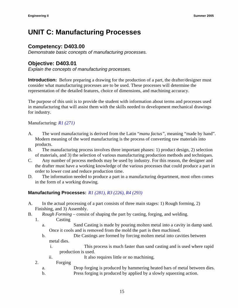
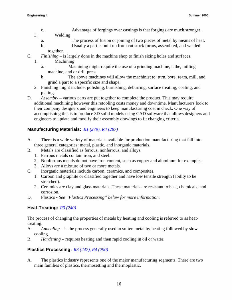
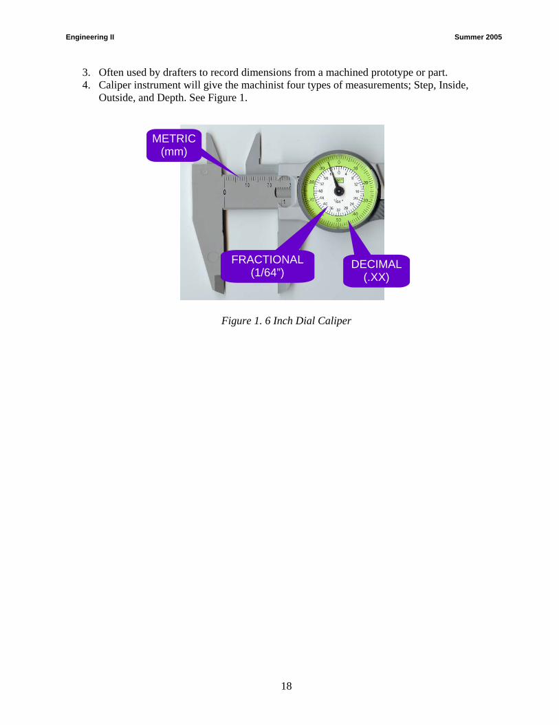
3. Often used by drafters to record dimensions from a machined prototype or part. 4. Caliper instrument will give the machinist four types of measurements; Step, Inside,
Outside, and Depth. See Figure 1.
METRIC (mm)
FRACTIONAL (1/64”)
DECIMAL (.XX)
Figure 1. 6 Inch Dial Caliper
18
Engineering II Summer 2005
UNIT C: Manufacturing Processes Competency: D403.00 Demonstrate the basic concepts of the manufacturing processes. Objective: D403.02 Explain the ANSI standards of applying annotations to a drawing that best describes the manufacturing process. Introduction: The purpose of this unit is to generate student awareness of the use of detailed annotations needed to describe the manufacturing process in the development of a part. Manufacturing Annotations: R1 (292-328), R2 (229-275) R3 (193-223), R4 (332-385) A. Two Kinds of manufacturing notes:
1. General Note – applies to general information about the part as a whole. Such as: FILLETS & ROUNDS ARE TO BE R.125. FINISH ALL OVER.
2. Local Note – is a note that is connected to a leader pointing to the appropriate area applying to a specific machining operation.
B. Drilling Terminology and Callouts
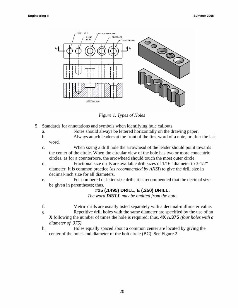
1. Drill - Is the process used to cut a cylindrical hole with a drill press and drill bit. 2. Boring - Enlarges the hole slightly and making it rounder and straighter. 3. Ream - To enlarge a hole to a more accurate size and surface quality. 4. Machined holes by their profiles (see Figure 1):
a. Through – a through hole is one that passes all the way through the object. b. Blind – a blind hole cuts into but does not pass completely through the
object. c. Counterbore - To enlarge the end of a drill hole to a specific diameter and
depth in order to recess a m ting part. ad. Countersink - To recess a hole with a conically (cone) shaped tool to
provide a seat for flat head screws. e. Spotface - The cutting of a shallow counterbore, usually about .0625 deep
(depth symbol is omitted). The spotface depth does not need to be specified. The spotface provides an accurate bearing surface for the underside of a bolt head.
19
Engineering II Summer 2005
Figure 1. Types of Holes
5. Standards for annotations and symbols when identifying hole callouts.
a. Notes should always be lettered horizontally on the drawing paper. b. Always attach leaders at the front of the first word of a note, or after the last
word. c. When sizing a drill hole the arrowhead of the leader should point towards
the center of the circle. When the circular view of the hole has two or more concentric circles, as for a counterbore, the arrowhead should touch the most outer circle.
d. Fractional size drills are available drill sizes of 1/16” diameter to 3-1/2” diameter. It is common practice (as recommended by ANSI) to give the drill size in decimal-inch size for all diameters.
e. For numbered or letter-size drills it is recommended that the decimal size be given in parentheses; thus,
#25 (.1495) DRILL, E (.250) DRILL. The word DRILL may be omitted from the note.
f. Metric drills are usually listed separately with a decimal-millimeter value. g. Repetitive drill holes with the same diameter are specified by the use of an
X following the number of times the hole is required; thus, 4X n.375 (four holes with a diameter of .375)
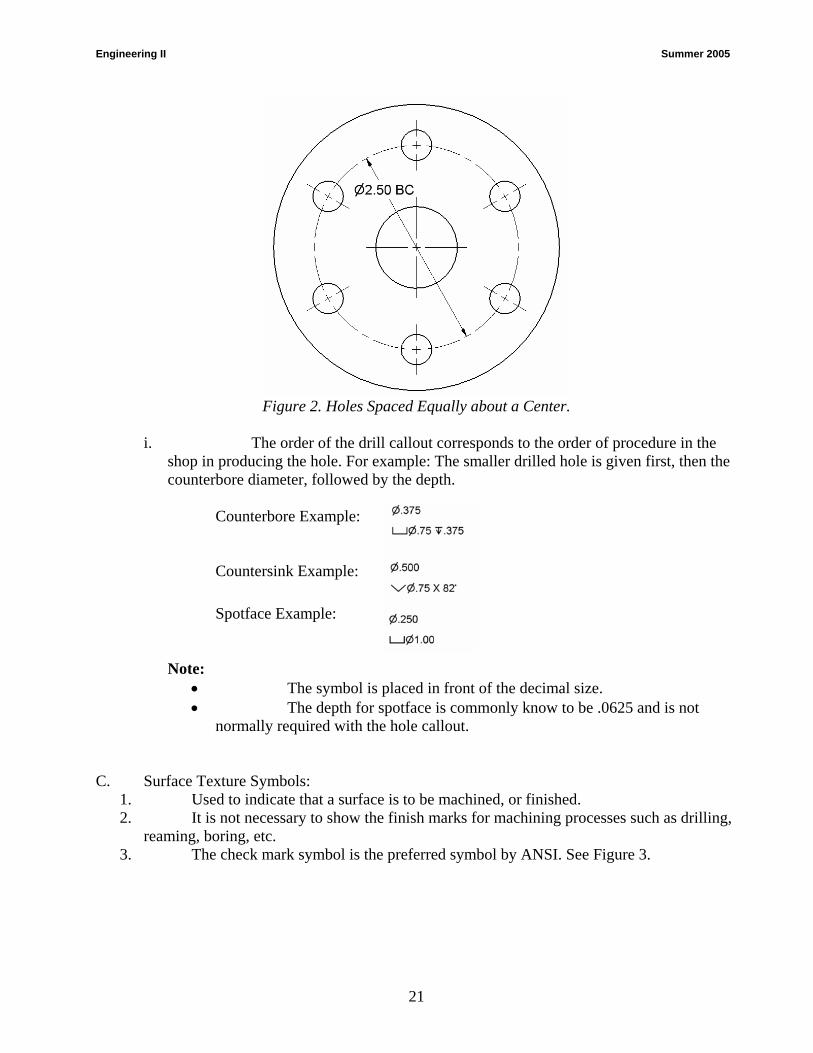
h. Holes equally spaced about a common center are located by giving the center of the holes and diameter of the bolt circle (BC). See Figure 2.
20
Engineering II Summer 2005
Figure 2. Holes Spaced Equally about a Center.
i. The order of the drill callout corresponds to the order of procedure in the
shop in producing the hole. For example: The smaller drilled hole is given first, then the counterbore diameter, followed by the depth.
Counterbore Example: Countersink Example:
Spotface Example:
Note:
• The symbol is placed in front of the decimal size. • The depth for spotface is commonly know to be .0625 and is not
normally required with the hole callout.
C. Surface Texture Symbols:
1. Used to indicate that a surface is to be machined, or finished. 2. It is not necessary to show the finish marks for machining processes such as drilling,
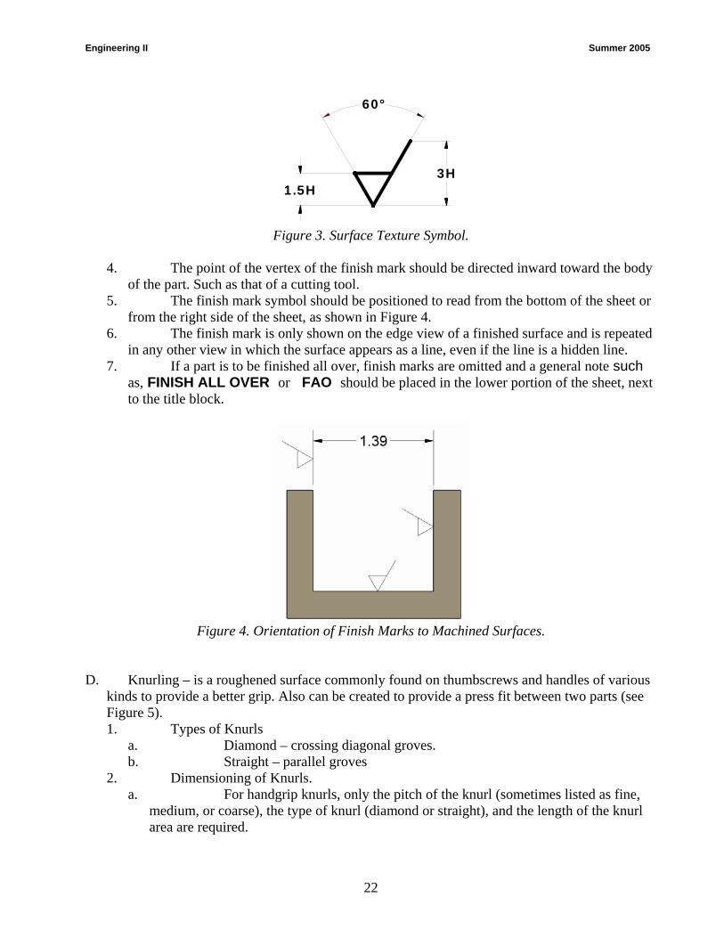
reaming, boring, etc. 3. The check mark symbol is the preferred symbol by ANSI. See Figure 3.
21
Engineering II Summer 2005
Figure 3. Surface Texture Symbol.
4. The point of the vertex of the finish mark should be directed inward toward the body
of the part. Such as that of a cutting tool. 5. The finish mark symbol should be positioned to read from the bottom of the sheet or
from the right side of the sheet, as shown in Figure 4. 6. The finish mark is only shown on the edge view of a finished surface and is repeated
in any other view in which the surface appears as a line, even if the line is a hidden line. 7. If a part is to be finished all over, finish marks are omitted and a general note such
as, FINISH ALL OVER or FAO should be placed in the lower portion of the sheet, next to the title block.
Figure 4. Orientation of Finish Marks to Machined Surfaces.
D. Knurling – is a roughened surface commonly found on thumbscrews and handles of various
kinds to provide a better grip. Also can be created to provide a press fit between two parts (see Figure 5). 1. Types of Knurls
a. Diamond – crossing diagonal groves. b. Straight – parallel groves
2. Dimensioning of Knurls. a. For handgrip knurls, only the pitch of the knurl (sometimes listed as fine,
medium, or coarse), the type of knurl (diamond or straight), and the length of the knurl area are required.
3H1.5H
60°
22

Engineering II Summer 2005
b. For a press fit type knurl, the tolerance diameter of the class of fit is given before the actual knurling note. The most commonly used diametrical pitches (DP) are 64 DP (coarse), 96 DP (medium), 128 DP (fine), and 160 DP (extra fine).
c. A knurl symbol (hatching pattern) does not have to be shown on the drawing when a local note is applied.
Figure 5. Dimensioning a Knurl.
1.89 .82
Ø1.25
96 DPSTRAIGHT KNURL
E. Fillets and Rounds - are normally found on cast, forged, and plastic parts.
1. The purpose of fillets and rounds is to add strength and protection from sharp edges. 2. A rounded interior corner is called a fillet. 3. A rounded exterior corner is called a round. 4. The presence of the curved surfaces is indicated only where they appear as arcs.
F. Runouts – is the method of representing fillets in connection with plane surfaces tangent to
cylinders. See Figure 6.
Figure 6. Conventional Fillets, Rounds, and Runouts.
G. Conventional Edges – rounded and filleted intersections eliminate sharp edges and
sometimes make it difficult to present a clear shape description. True projection may actually be
23
Engineering II Summer 2005
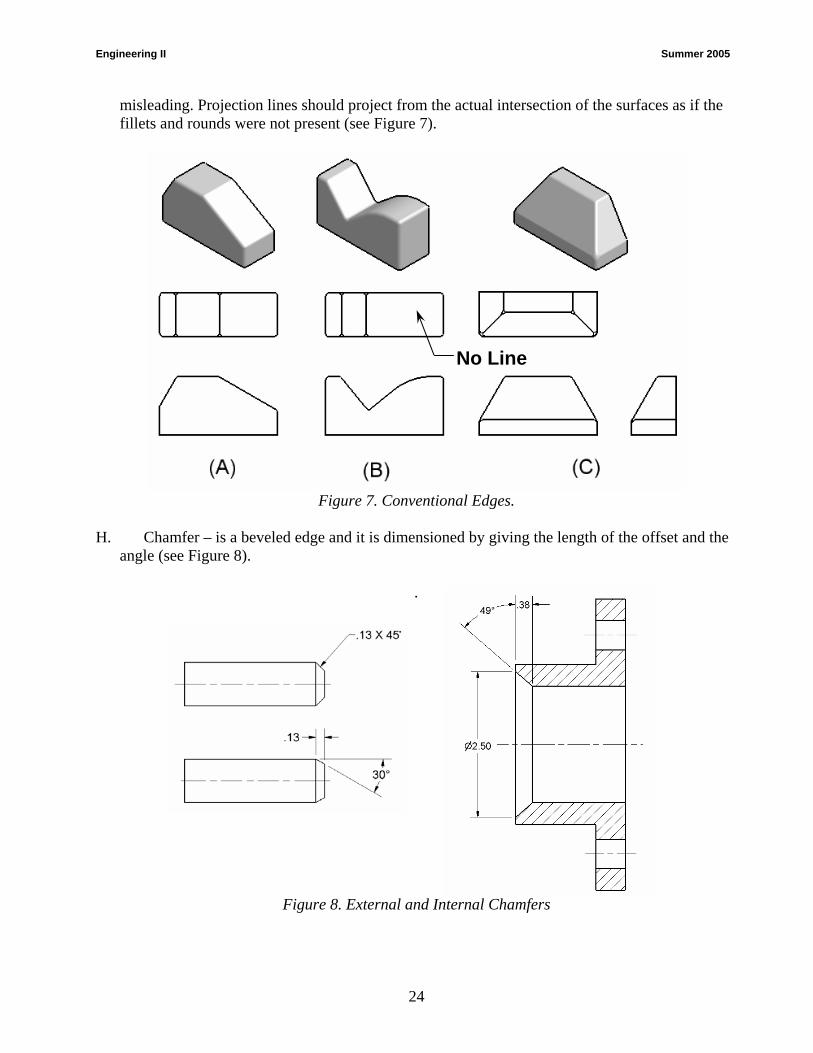
misleading. Projection lines should project from the actual intersection of the surfaces as if the fillets and rounds were not present (see Figure 7).
Figure 7. Conventional Edges.
No Line
H. Chamfer – is a beveled edge and it is dimensioned by giving the length of the offset and the
angle (see Figure 8).
.
Figure 8. External and Internal Chamfers
24

Engineering II Summer 2005
UNIT C: Manufacturing Processes
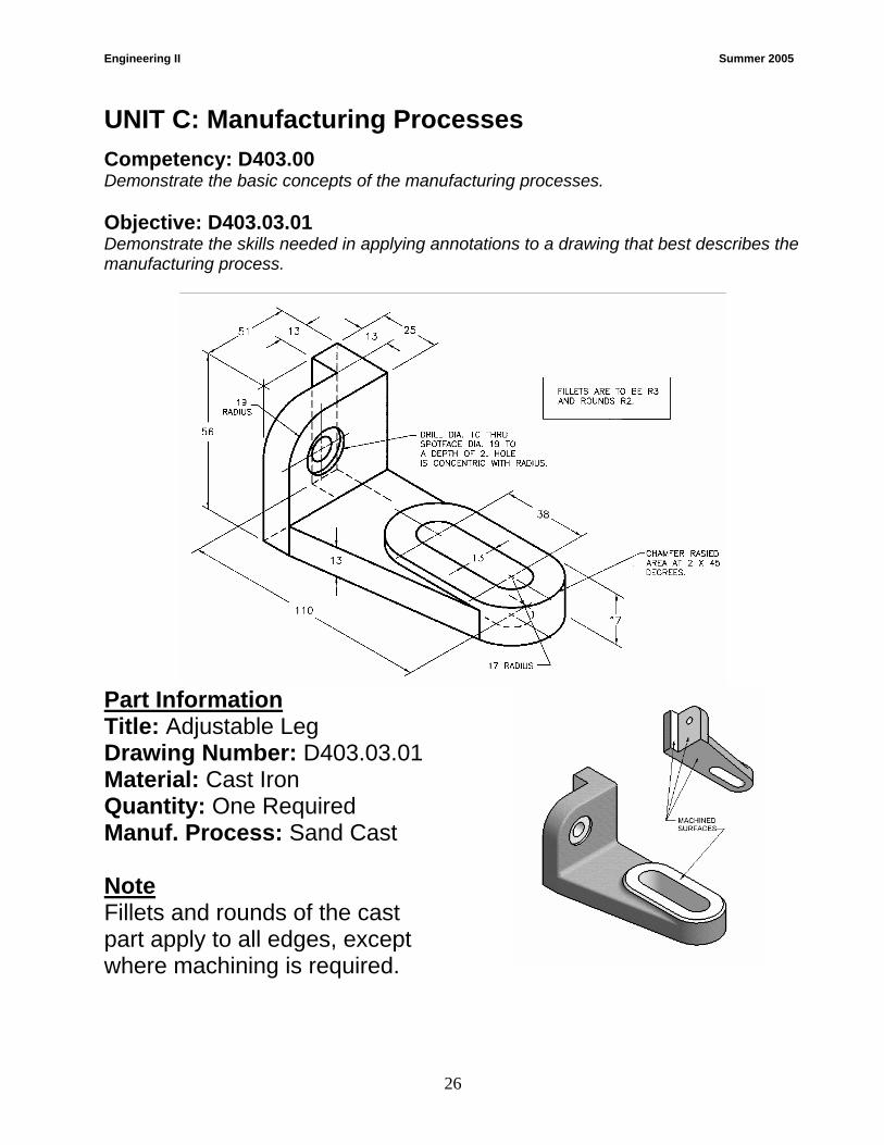
Competency: D403.00 Demonstrate the basic concepts of the manufacturing processes. Objective: D403.03.01 Demonstrate the skills needed in applying annotations to a drawing that best describes the manufacturing process. Requirement: Using the equipment provided, construct a working drawing that best describes the manufacturing processes required to produce the part, “The Adjustable Leg”.
1. When plotted the drawing should fit on size “A" sheet of paper at a scale of 1:1.
2. Balance the drawing within the working area. Border and title block layout are to be assigned by the test Administrator.
3. Include your name, problem number (D403.03.001), scale, and date in the title block, as assigned by the test Administrator.
4. Save your work on the diskette provided or as directed by the test Administrator.
5. Time Limit = 90 minutes.
6. Dimension the drawing according to ANSI standards and add finish marks where required.
7. Use the following specifications for drawing set-up:
a. Units = Metric (mm)
b. Drawing Area (Limits) = Size “A” paper (11” X 8.5” landscape)
c. Title block & border layout are to be assigned by the test Administrator.
Assessment: The 2D CAD drawing should be evaluated based on the following criteria:
Criteria Point Range Drawing Set-up 10 points Accuracy and Shape Representation 25 points Feature Representation 30 points Dimensioning and Annotations 25 points Layout and Title Block Information 10 points
25
Engineering II Summer 2005
UNIT C: Manufacturing Processes
Competency: D403.00 Demonstrate the basic concepts of the manufacturing processes. Objective: D403.03.01 Demonstrate the skills needed in applying annotations to a drawing that best describes the manufacturing process.
Part Information Title: Adjustable Leg Drawing Number: D403.03.01 Material: Cast Iron Quantity: One Required Manuf. Process: Sand Cast Note Fillets and rounds of the cast part apply to all edges, except where machining is required.
26
Engineering II Summer 2005
27
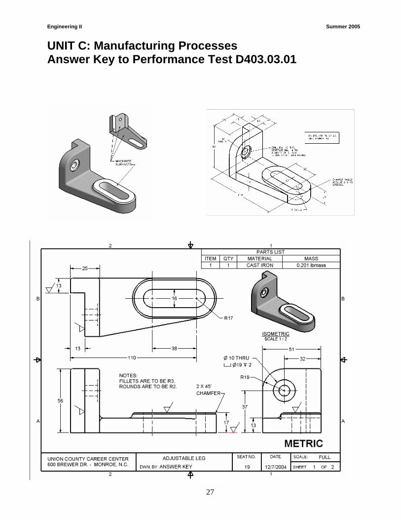
UNIT C: Manufacturing Processes Answer Key to Performance Test D403.03.01
Engineering II Summer 2005
28
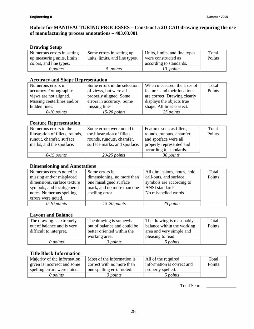
Rubric for MANUFACTURING PROCESSES – Construct a 2D CAD drawing requiring the use of manufacturing process annotations – 403.03.001
Drawing Setup Numerous errors in setting up measuring units, limits, colors, and line types.
Some errors in setting up units, limits, and line types.
Units, limits, and line types were constructed as according to standards.
Total Points
0 points 5 points 10 points Accuracy and Shape Representation Numerous errors in accuracy. Orthographic views are not aligned. Missing centerlines and/or hidden lines.
Some errors in the selection of views, but were all properly aligned. Some errors in accuracy. Some missing lines.
When measured, the sizes of features and their locations are correct. Drawing clearly displays the objects true shape. All lines correct.
Total Points
0-10 points 15-20 points 25 points Feature Representation Numerous errors in the illustration of fillets, rounds, runout, chamfer, surface marks, and the spotface.
Some errors were noted in the illustration of fillets, rounds, runouts, chamfer, surface marks, and spotface.
Features such as fillets, rounds, runouts, chamfer, and spotface were all properly represented and according to standards.
Total Points
0-15 points 20-25 points 30 points Dimensioning and Annotations Numerous errors noted in missing and/or misplaced dimensions, surface texture symbols, and local/general notes. Numerous spelling errors were noted.
Some errors in dimensioning, no more than one misaligned surface mark, and no more than one spelling error.
All dimensions, notes, hole call-outs, and surface symbols are according to ANSI standards. No misspelled words.
Total Points
0-10 points 15-20 points 25 points Layout and Balance The drawing is extremely out of balance and is very difficult to interpret.
The drawing is somewhat out of balance and could be better oriented within the working area.
The drawing is reasonably balance within the working area and very simple and pleasing to read.
Total Points
0 points 3 points 5 points Title Block Information Majority of the information given is incorrect and some spelling errors were noted.
Most of the information is correct with no more than one spelling error noted.
All of the required information is correct and properly spelled.
Total Points
0 points 3 points 5 points
Total Score
Engineering II Summer 2005
29
Dimensioning and Conventional Tolerancing
004. Demonstrate intermediate dimensioning and conventional tolerancing techniques 004.01 Explain intermediate dimensioning techniques 004.02 Explain procedures for determining tolerance dimensions 004.03 Construct drawings that require conventional tolerances
Engineering II Summer 2005
30
UNIT D: Dimensioning and Conventional Tolerancing
Competency: D404.00 Demonstrate intermediate dimensioning and conventional tolerancing techniques.
Objective: D404.01 Explain intermediate dimensioning techniques. Introduction: The purpose of this unit is to cover intermediate dimensioning techniques and the area of tolerance dimensioning. When students begin dimensioning parts, especially parts that interact within an assembly, it is critical that they understand the differences between clearance and interference fits. Modern industry relies on interchangeable manufacturing so that parts can be manufactured in widely separate localities and then brought together for assembly without further machining. After this unit, students should be able to define terminology related to tolerance dimensioning, identify different types of fits given two dimensioned parts, and correctly apply limit dimensions to a part when given the type of fit.
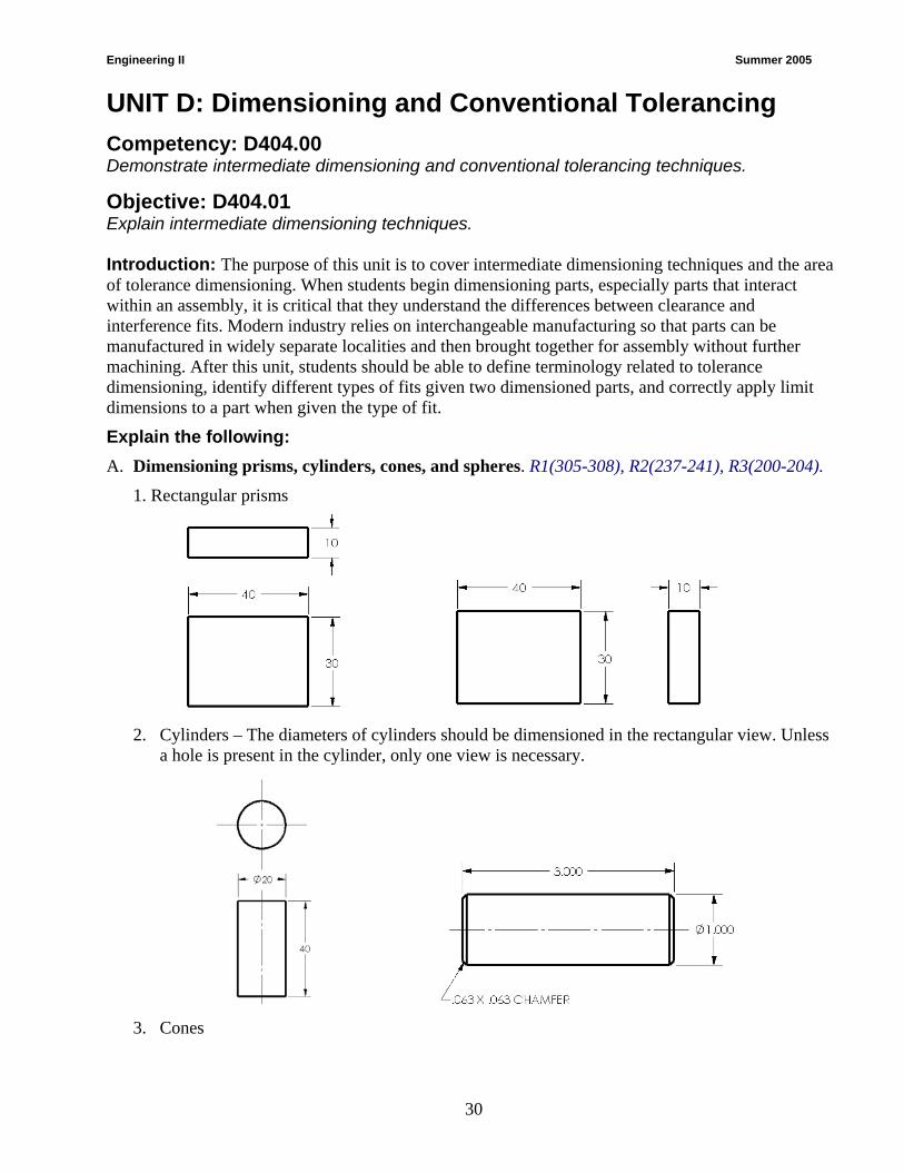
Explain the following: A. Dimensioning prisms, cylinders, cones, and spheres. R1(305-308), R2(237-241), R3(200-204).
1. Rectangular prisms
2. Cylinders – The diameters of cylinders should be dimensioned in the rectangular view. Unless
a hole is present in the cylinder, only one view is necessary.
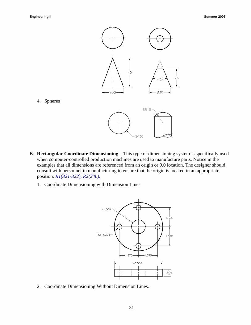
3. Cones
Engineering II Summer 2005
31
4. Spheres
B. Rectangular Coordinate Dimensioning – This type of dimensioning system is specifically used when computer-controlled production machines are used to manufacture parts. Notice in the examples that all dimensions are referenced from an origin or 0,0 location. The designer should consult with personnel in manufacturing to ensure that the origin is located in an appropriate position. R1(321-322), R2(246).
1. Coordinate Dimensioning with Dimension Lines
2. Coordinate Dimensioning Without Dimension Lines.

Engineering II Summer 2005
32
C. Tabular Dimensioning. Tabular dimensioning is used when a series of parts consists of the same features or geometry but vary in dimension. Letters are used in place of dimension values, and the values are then placed in a table. Most standard parts are dimensioned this way in catalogs, the machinery handbook, and in the back of most textbooks. R1(320-321), R2(471).
D. Dual Dimensioning – used to show both metric and decimal inch dimensioning on the same
drawing. R1(299-300), R2(234), R3(219). 1. Position Method – millimeter value is placed above (or below) the inch value
or separated by a dash.

Engineering II Summer 2005
33
2. Bracket Method – millimeter value is enclosed in square brackets. A note should be placed on the drawing such as: DIMENSIONS IN [ ] ARE MILLIMETERS.
Engineering II Summer 2005
34
UNIT D: Dimensioning and Conventional Tolerancing
Competency: D404.00 Demonstrate intermediate dimensioning and conventional tolerancing techniques.
Objective: D404.02 Explain procedures for determining tolerance dimensions.
Explain the following: A. Define the following terms: R1(330-339), R2(246-249), R3(213-217).
1. Interchangeable - Parts that are made to easily fit mating parts without additional machining at the time of assembly.
2. Actual size - The actual size is the measured size. 3. Basic size - The basic size is the size to which allowances and tolerances are added to get the
limits of size. 4. Nominal size - The nominal size is a designation used for general identification. Typically this
is a fraction when working in inches. 5. Design size - The design size is the size from which the limits of size are derived by the
application of tolerances. 6. Tolerance - The total amount a single dimension can vary. The difference between the upper
and lower limits. 7. Allowance - Allowance is the minimum clearance or maximum interference intended between
the maximum material condition (MMC) of mating parts. Example: Smallest hole with the largest shaft. The tightest permissible fit.
8. Limit dimensions - A tolerancing method showing the maximum and minimum size values. The maximum dimension is placed above the minimum dimension. When expressed in a single line, the lower limit precedes the upper limit.
9. Unilateral tolerance - A tolerance that allows variation in one direction. 10. Bilateral tolerance - A tolerance that allows variation in both directions from the design size. 11. Clearance fit - A fit between mating parts having limits of size so prescribed that a clearance
always results in assembly. 12. Interference fit - A fit between mating parts having limits of size so prescribed that
interference always results in assembly. 13. Transition fit - A fit between mating parts having limits of size so prescribed as to partially or
wholly overlap, so that either a clearance or interference may result in assembly. B. Tolerance dimensioning.
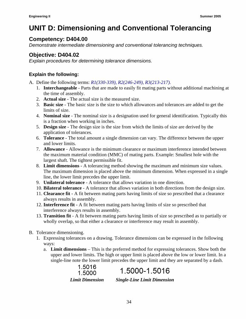
1. Expressing tolerances on a drawing. Tolerance dimensions can be expressed in the following ways: a. Limit dimensions – This is the preferred method for expressing tolerances. Show both the
upper and lower limits. The high or upper limit is placed above the low or lower limit. In a single-line note the lower limit precedes the upper limit and they are separated by a dash.
Limit Dimension Single-Line Limit Dimension
Engineering II Summer 2005
35
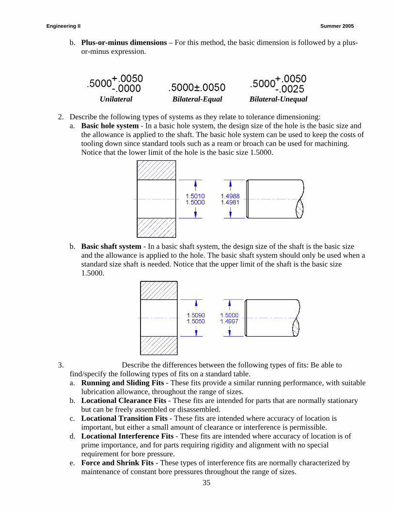
b. Plus-or-minus dimensions – For this method, the basic dimension is followed by a plus-or-minus expression.
Unilateral Bilateral-Equal Bilateral-Unequal
2. Describe the following types of systems as they relate to tolerance dimensioning: a. Basic hole system - In a basic hole system, the design size of the hole is the basic size and
the allowance is applied to the shaft. The basic hole system can be used to keep the costs of tooling down since standard tools such as a ream or broach can be used for machining. Notice that the lower limit of the hole is the basic size 1.5000.
b. Basic shaft system - In a basic shaft system, the design size of the shaft is the basic size
and the allowance is applied to the hole. The basic shaft system should only be used when a standard size shaft is needed. Notice that the upper limit of the shaft is the basic size 1.5000.
3. Describe the differences between the following types of fits: Be able to
find/specify the following types of fits on a standard table. a. Running and Sliding Fits - These fits provide a similar running performance, with suitable
lubrication allowance, throughout the range of sizes. b. Locational Clearance Fits - These fits are intended for parts that are normally stationary
but can be freely assembled or disassembled. c. Locational Transition Fits - These fits are intended where accuracy of location is
important, but either a small amount of clearance or interference is permissible. d. Locational Interference Fits - These fits are intended where accuracy of location is of
prime importance, and for parts requiring rigidity and alignment with no special requirement for bore pressure.
e. Force and Shrink Fits - These types of interference fits are normally characterized by maintenance of constant bore pressures throughout the range of sizes.

Engineering II Summer 2005
36
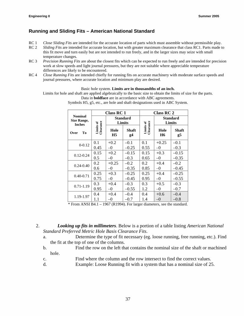
C. Looking up specified fits on tables.
1. Looking up fits in inches. Below is a portion of a table listing American National Standard Running and Sliding Fits. One of the first things to notice about the table is that all of the values are in thousandths of an inch (so a value of +1 is really + .001). a. Determine the type of fit necessary (eg. close sliding fit, sliding fit, precision
running fit, etc.). Find the fit at the top of one of the columns labeled as RC1, RC2, etc. b. Find the row on the left that contains the range for the nominal size of the
shaft or machined hole. c. Find where the column and the row intersect to find the correct values. d. Example: Sliding fit with a system that has a nominal size of 1.500.
Engineering II Summer 2005
37
Running and Sliding Fits – American National Standard RC 1 Close Sliding Fits are intended for the accurate location of parts which must assemble without permissible play. RC 2 Sliding Fits are intended for accurate location, but with greater maximum clearance that class RC1. Parts made to
this fit move and turn easily but are not intended to run freely, and in the larger sizes may seize with small temperature changes.
RC 3 Precision Running Fits are about the closest fits which can be expected to run freely and are intended for precision work at slow speeds and light journal pressures, but they are not suitable where appreciable temperature differences are likely to be encountered.
RC 4 Close Running Fits are intended chiefly for running fits on accurate machinery with moderate surface speeds and journal pressures, where accurate location and minimum play are desired.
Basic hole system. Limits are in thousandths of an inch.
Limits for hole and shaft are applied algebraically to the basic size to obtain the limits of size for the parts. Data in boldface are in accordance with ABC agreements.
Symbols H5, g5, etc., are hole and shaft designations used in ABC System.
Class RC 1 Class RC 2 Standard
Limits Standard
Limits
Nominal
Size Range, Inches
Over To
Lim
its o
f C
lear
ance
Hole H5
Shaft g4 L
imits
of
Cle
aran
ce
Hole H6
Shaft g5
0-0.12 0.1 0.45
+0.2 –0
–0.1 –0.25
0.1 0.55
+0.25 –0
–0.1 –0.3
0.12-0.24 0.15 0.5
+0.2 –0
–0.15 –0.3
0.15 0.65
+0.3 –0
–0.15 –0.35
0.24-0.40 0.2 0.6
+0.25 –0
–0.2 –0.35
0.2 0.85
+0.4 –0
–0.2 –0.45
0.40-0.71 0.25 0.75
+0.3 –0
–0.25 –0.45
0.25 0.95
+0.4 –0
–0.25 –0.55
0.71-1.19 0.3 0.95
+0.4 –0
–0.3 –0.55
0.3 1.2
+0.5 –0
–0.3 –0.7
1.19-1.97 0.4 1.1
+0.4 –0
–0.4 –0.7
0.4 1.4
+0.6 –0
–0.4 –0.8
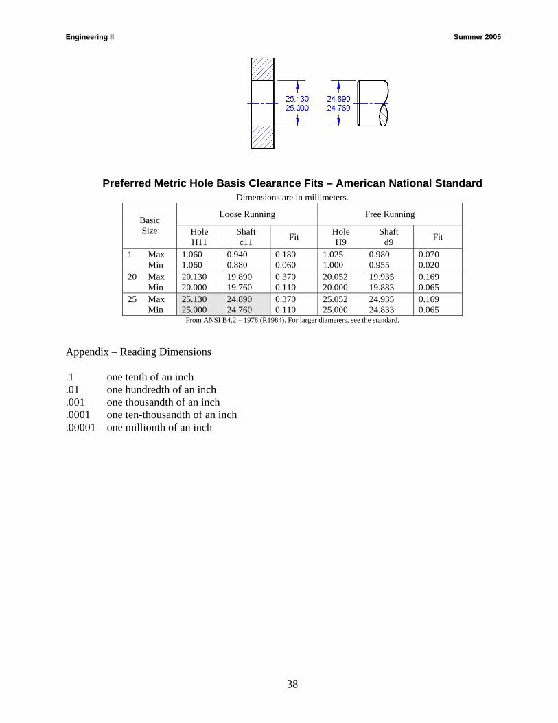
* From ANSI B4.1 – 1967 (R1994). For larger diameters, see the standard. 2. Looking up fits in millimeters. Below is a portion of a table listing American National
Standard Preferred Metric Hole Basis Clearance Fits. a. Determine the type of fit necessary (eg. loose running, free running, etc.). Find
the fit at the top of one of the columns. b. Find the row on the left that contains the nominal size of the shaft or machined
hole. c. Find where the column and the row intersect to find the correct values. d. Example: Loose Running fit with a system that has a nominal size of 25.
Engineering II Summer 2005
38
Preferred Metric Hole Basis Clearance Fits – American National Standard Dimensions are in millimeters.
Loose Running Free Running Basic Size Hole
H11 Shaft c11 Fit Hole
H9 Shaft
d9 Fit
1 Max Min
1.060 1.060
0.940 0.880
0.180 0.060
1.025 1.000
0.980 0.955
0.070 0.020
20 Max Min
20.130 20.000
19.890 19.760
0.370 0.110
20.052 20.000
19.935 19.883
0.169 0.065
25 Max Min
25.130 25.000
24.890 24.760
0.370 0.110
25.052 25.000
24.935 24.833
0.169 0.065
From ANSI B4.2 – 1978 (R1984). For larger diameters, see the standard.
Appendix – Reading Dimensions .1 one tenth of an inch .01 one hundredth of an inch .001 one thousandth of an inch .0001 one ten-thousandth of an inch .00001 one millionth of an inch
Engineering II Summer 2005
39
UNIT D: Dimensioning and Conventional Tolerancing
Competency: D404.00 Demonstrate intermediate dimensioning and tolerancing techniques.
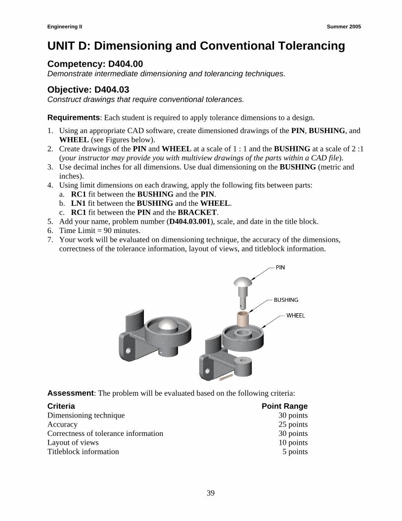
Objective: D404.03 Construct drawings that require conventional tolerances. Requirements: Each student is required to apply tolerance dimensions to a design.
1. Using an appropriate CAD software, create dimensioned drawings of the PIN, BUSHING, and WHEEL (see Figures below).
2. Create drawings of the PIN and WHEEL at a scale of 1 : 1 and the BUSHING at a scale of 2 :1 (your instructor may provide you with multiview drawings of the parts within a CAD file).
3. Use decimal inches for all dimensions. Use dual dimensioning on the BUSHING (metric and inches).
4. Using limit dimensions on each drawing, apply the following fits between parts: a. RC1 fit between the BUSHING and the PIN. b. LN1 fit between the BUSHING and the WHEEL. c. RC1 fit between the PIN and the BRACKET.
5. Add your name, problem number (D404.03.001), scale, and date in the title block. 6. Time Limit = 90 minutes. 7. Your work will be evaluated on dimensioning technique, the accuracy of the dimensions,
correctness of the tolerance information, layout of views, and titleblock information.
Assessment: The problem will be evaluated based on the following criteria:
Criteria Point Range Dimensioning technique 30 points Accuracy 25 points Correctness of tolerance information 30 points Layout of views 10 points Titleblock information 5 points

Engineering II Summer 2005
40
UNIT D: Dimensioning and Conventional Tolerancing
Competency: D404.00 Demonstrate intermediate dimensioning and tolerancing techniques.
Objective: D404.03 Construct drawings that require conventional tolerances.
Engineering II Summer 2005
41
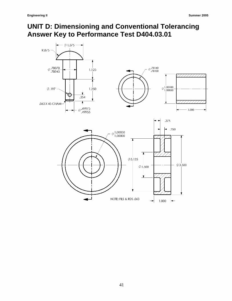
UNIT D: Dimensioning and Conventional Tolerancing Answer Key to Performance Test D404.03.01
Engineering II Summer 2005
42
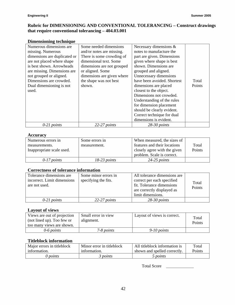
Rubric for DIMENSIONING AND CONVENTIONAL TOLERANCING – Construct drawings that require conventional tolerancing – 404.03.001 Dimensioning technique Numerous dimensions are missing. Numerous dimensions are duplicated or are not placed where shape is best shown. Arrowheads are missing. Dimensions are not grouped or aligned. Dimensions are crowded. Dual dimensioning is not used.
Some needed dimensions and/or notes are missing. There is some crowding of dimensional text. Some dimensions are not grouped or aligned. Some dimensions are given where the shape was not best shown.
Necessary dimensions & notes to manufacture the part are given. Dimensions given where shape is best shown. Dimensions are grouped and aligned. Unnecessary dimensions have been avoided. Shortest dimensions are placed closest to the object. Dimensions not crowded. Understanding of the rules for dimension placement should be clearly evident. Correct technique for dual dimensions is evident.
Total Points
0-21 points 22-27 points 28-30 points Accuracy Numerous errors in measurements. Inappropriate scale used.
Some errors in measurement.
When measured, the sizes of features and their locations closely agree with the given problem. Scale is correct.
Total Points
0-17 points 18-23 points 24-25 points Correctness of tolerance information Tolerance dimensions are incorrect. Limit dimensions are not used.
Some minor errors in specifying the fits.
All tolerance dimensions are correct per each specified fit. Tolerance dimensions are correctly displayed as limit dimensions.
Total Points
0-21 points 22-27 points 28-30 points Layout of views Views are out of projection (not lined up). Too few or too many views are shown.
Small error in view alignment.
Layout of views is correct. Total Points
0-6 points 7-8 points 9-10 points Titleblock information Major errors in titleblock information.
Minor error in titleblock information.
All titleblock information is shown and spelled correctly.
Total Points
0 points 3 points 5 points Total Score
Engineering II Summer 2005
43
Sectional Views 005. Demonstrate the correct techniques for preparing sectional views 005.01 Explain the concepts and principles of sectional views 005.02 Construct sectional views

Engineering II Summer 2005
44
UNIT E: Sectional Views Competency: D405.00 Demonstrate the correct techniques for preparing sectional views.
Objective: D405.01 Explain the concepts and principles of sectional views. Introduction: The purpose of a section is to show interior detail or space. By means of a limited number of carefully selected views, the external features of the most complicated designs can be fully described. However, we often need to show interiors that cannot be illustrated clearly by hidden lines. We show such interiors by slicing through the object much as we cut through an apple or melon. A cutaway view of the part is then drawn; such views are called sectional views, cross sections, or simply sections.
To produce a sectional view, a cutting plane is assumed to pass through the part. The cutting plane is then removed, and the two halves are drawn apart, exposing the interior construction. In which case, the direction of sight is towards one half of the object. The other half is then mentally discarded.
Drafters use sectional views to improve the clarity of complex objects when internal surfaces result in too many hidden lines. Special conventions are used to make a sectional view easy to understand. Creating a sectional view with CAD can be a complicated operation. Understanding thoroughly the concepts of sectional views will help the drafter create the drawing with the CAD software.
References R1(199-228);R2(276-315);R3(252-273)
Sections - Explain the following: A. The purpose of a section is to show interior detail or space of an object or entity. B. Identify and explain the following
concerning cutting plane lines (see Figure 1):
Figure 1. Cutting-Plane Line.
1. Cutting plane lines are used to indicate where the section or cut is made.
2. Arrowheads on a cutting plane line indicate the direction of sight.
3. The two most commonly used cutting plane lines are: a. A heavy line of altering long dashes (3/4” to 1 ½”) with a pair of short dashes (1/8”)
long. b. Uniform length dashes (¼”) with uniform spacing between.
C. Identify and explain the following concerning section lines (see Figure 2):
Engineering II Summer 2005
45
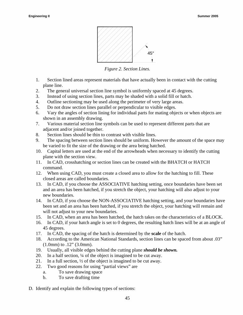
45°
Figure 2. Section Lines.
1. Section lined areas represent materials that have actually been in contact with the cutting
plane line. 2. The general universal section line symbol is uniformly spaced at 45 degrees. 3. Instead of using section lines, parts may be shaded with a solid fill or hatch. 4. Outline sectioning may be used along the perimeter of very large areas. 5. Do not draw section lines parallel or perpendicular to visible edges. 6. Vary the angles of section lining for individual parts for mating objects or when objects are
shown in an assembly drawing. 7. Various material section line symbols can be used to represent different parts that are
adjacent and/or joined together. 8. Section lines should be thin to contrast with visible lines. 9. The spacing between section lines should be uniform. However the amount of the space may
be varied to fit the size of the drawing or the area being hatched. 10. Capital letters are used at the end of the arrowheads when necessary to identify the cutting
plane with the section view. 11. In CAD, crosshatching or section lines can be created with the BHATCH or HATCH
command. 12. When using CAD, you must create a closed area to allow for the hatching to fill. These
closed areas are called boundaries. 13. In CAD, if you choose the ASSOCIATIVE hatching setting, once boundaries have been set
and an area has been hatched, if you stretch the object, your hatching will also adjust to your new boundaries.
14. In CAD, if you choose the NON-ASSOCIATIVE hatching setting, and your boundaries have been set and an area has been hatched, if you stretch the object, your hatching will remain and will not adjust to your new boundaries.
15. In CAD, when an area has been hatched, the hatch takes on the characteristics of a BLOCK. 16. In CAD, if your hatch angle is set to 0 degrees, the resulting hatch lines will be at an angle of
45 degrees. 17. In CAD, the spacing of the hatch is determined by the scale of the hatch. 18. According to the American National Standards, section lines can be spaced from about .03”
(1.0mm) to .12” (3.0mm). 19. Usually, all visible edges behind the cutting plane should be shown. 20. In a half section, ¼ of the object is imagined to be cut away. 21. In a full section, ½ of the object is imagined to be cut away. 22. Two good reasons for using “partial views” are
a. To save drawing space b. To save drafting time
D. Identify and explain the following types of sections:
Engineering II Summer 2005
46
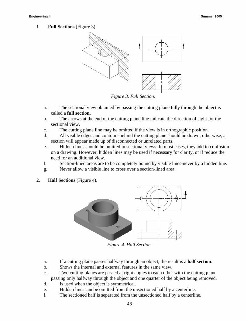
1. Full Sections (Figure 3).
Figure 3. Full Section.
a. The sectional view obtained by passing the cutting plane fully through the object is
called a full section. b. The arrows at the end of the cutting plane line indicate the direction of sight for the
sectional view. c. The cutting plane line may be omitted if the view is in orthographic position. d. All visible edges and contours behind the cutting plane should be drawn; otherwise, a
section will appear made up of disconnected or unrelated parts. e. Hidden lines should be omitted in sectional views. In most cases, they add to confusion
on a drawing. However, hidden lines may be used if necessary for clarity, or if reduce the need for an additional view.
f. Section-lined areas are to be completely bound by visible lines-never by a hidden line. g. Never allow a visible line to cross over a section-lined area.
2. Half Sections (Figure 4).
Figure 4. Half Section.
a. If a cutting plane passes halfway through an object, the result is a half section. b. Shows the internal and external features in the same view. c. Two cutting planes are passed at right angles to each other with the cutting plane
passing only halfway through the object and one quarter of the object being removed. d. Is used when the object is symmetrical. e. Hidden lines can be omitted from the unsectioned half by a centerline. f. The sectioned half is separated from the unsectioned half by a centerline.
Engineering II Summer 2005
47
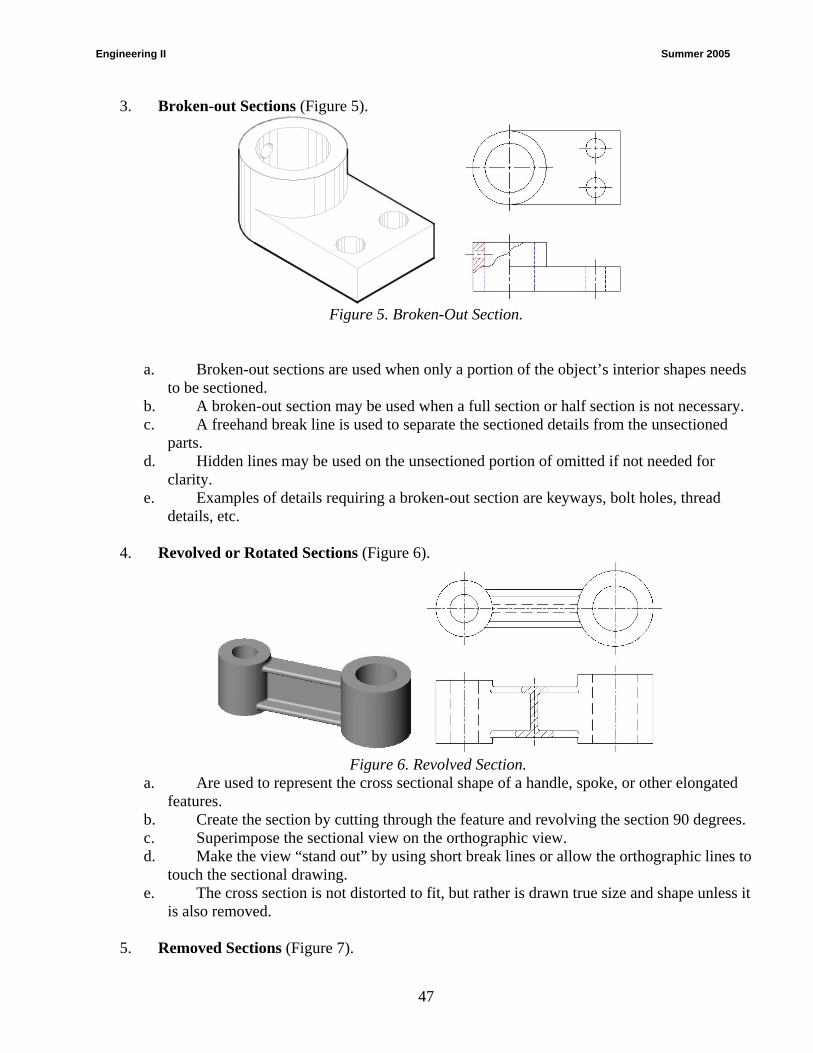
3. Broken-out Sections (Figure 5).
Figure 5. Broken-Out Section.
a. Broken-out sections are used when only a portion of the object’s interior shapes needs to be sectioned.
b. A broken-out section may be used when a full section or half section is not necessary. c. A freehand break line is used to separate the sectioned details from the unsectioned
parts. d. Hidden lines may be used on the unsectioned portion of omitted if not needed for
clarity. e. Examples of details requiring a broken-out section are keyways, bolt holes, thread
details, etc.
4. Revolved or Rotated Sections (Figure 6).
Figure 6. Revolved Section.
a. Are used to represent the cross sectional shape of a handle, spoke, or other elongated features.
b. Create the section by cutting through the feature and revolving the section 90 degrees. c. Superimpose the sectional view on the orthographic view. d. Make the view “stand out” by using short break lines or allow the orthographic lines to
touch the sectional drawing. e. The cross section is not distorted to fit, but rather is drawn true size and shape unless it
is also removed.
5. Removed Sections (Figure 7).
Engineering II Summer 2005
48
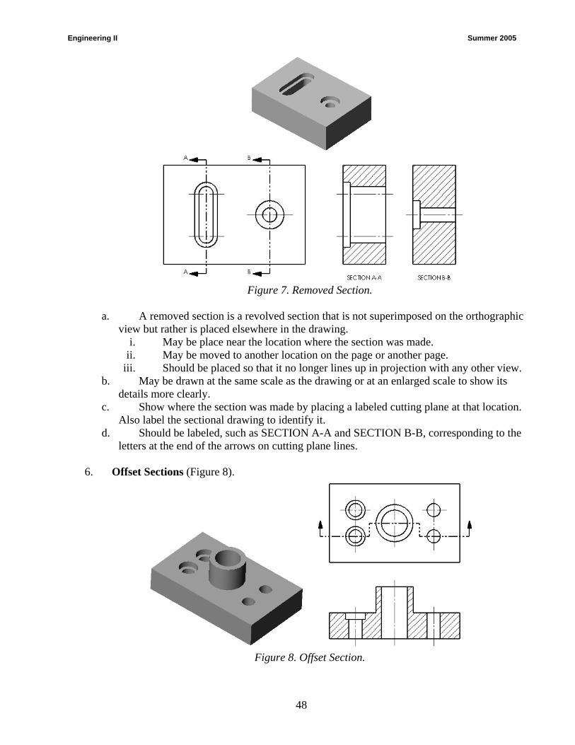
Figure 7. Removed Section.
a. A removed section is a revolved section that is not superimposed on the orthographic
view but rather is placed elsewhere in the drawing. i. May be place near the location where the section was made.
ii. May be moved to another location on the page or another page. iii. Should be placed so that it no longer lines up in projection with any other view.
b. May be drawn at the same scale as the drawing or at an enlarged scale to show its details more clearly.
c. Show where the section was made by placing a labeled cutting plane at that location. Also label the sectional drawing to identify it.
d. Should be labeled, such as SECTION A-A and SECTION B-B, corresponding to the letters at the end of the arrows on cutting plane lines.
6. Offset Sections (Figure 8).
Figure 8. Offset Section.
Engineering II Summer 2005
49
a. When sectioning through irregular objects, it is often desirable to show features that do not lie in a straight line by “offsetting” or bending the cutting plane. Such a section is called an offset section.
b. The cutting plane is bent at one or more 90-degree angles so that it will pass through important features.
c. The change of plane that occurs when the cutting plane is bent 90 degrees is not represented with lines in the sectional view.
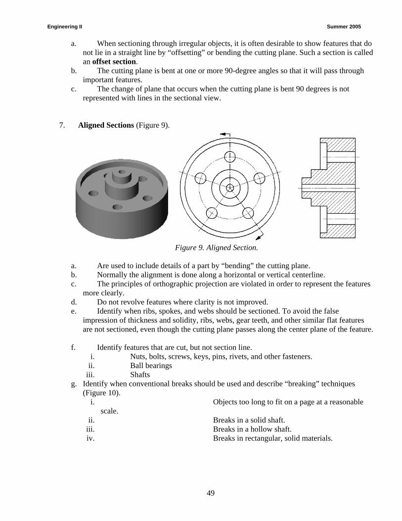
7. Aligned Sections (Figure 9).
Figure 9. Aligned Section.
a. Are used to include details of a part by “bending” the cutting plane. b. Normally the alignment is done along a horizontal or vertical centerline. c. The principles of orthographic projection are violated in order to represent the features
more clearly. d. Do not revolve features where clarity is not improved. e. Identify when ribs, spokes, and webs should be sectioned. To avoid the false
impression of thickness and solidity, ribs, webs, gear teeth, and other similar flat features are not sectioned, even though the cutting plane passes along the center plane of the feature.
f. Identify features that are cut, but not section line. i. Nuts, bolts, screws, keys, pins, rivets, and other fasteners.
ii. Ball bearings iii. Shafts
g. Identify when conventional breaks should be used and describe “breaking” techniques (Figure 10).
i. Objects too long to fit on a page at a reasonable scale.
ii. Breaks in a solid shaft. iii. Breaks in a hollow shaft. iv. Breaks in rectangular, solid materials.

Engineering II Summer 2005
50
Figure 10. Conventional Breaks.
Engineering II Summer 2005
51
UNIT E: Performance Assessment – Sectional Views
Competency: D405.00 Demonstrate the correct techniques for preparing sectional views.
Objective: D405.02 Construct sectional views. Requirements: Each student is required to create a sectional view from the (3) views, (front, top and right side) of the BEARING given in Figure 1. Construct a Full Sectional View of the problem. Recreate the (3) views given. Add a sectional view of the best view necessary to describe the part. IMPORTANT NOTE: Your instructor may ask you to create a 3D model of the object first and then extract the required views from the model instead of completing this assignment as a 2D drawing. If this is the case, the correctness of your drawing is still what is being evaluated.
1. Recreate the front, top and right side views shown in Figure 1. You are then required to create the best view or views to show a cross section of the part.
2. Drawing Scale 1 : 1. Print or plot as instructed by your instructor. 3. Use accepted drafting standards for lines, titleblock, etc. as instructed by your instructor. 4. Add your name, problem number (405.02.001), scale, and date in the title block. 5. Time Limit = 90 minutes. 6. An effort should be made to create a balanced appearance. 7. Your work should reflect an understanding of sectional views. 8. Use the following specifications:
a. Units –Decimal (0 precision) b. Grid – 10 c. Limits – Set as necessary d. Snap - 5 e. Layers
Layer Title Linetype Color VISIBLE CONTINUOUS BLACK (WHITE) HIDDEN HIDDENX2 DARK BLUE CENTER CENTERX2 RED DIMENSIONS CONTINUOUS RED
Assessment: The problem will be evaluated based on the following criteria:
Criteria Point Range Drawing Setup 15 points Accuracy of Section View 40 points Lines 15 points Dimensioning Text and Notes 15 points Layout & balance 15 points
Sectional Views Performance Assessment Drawing
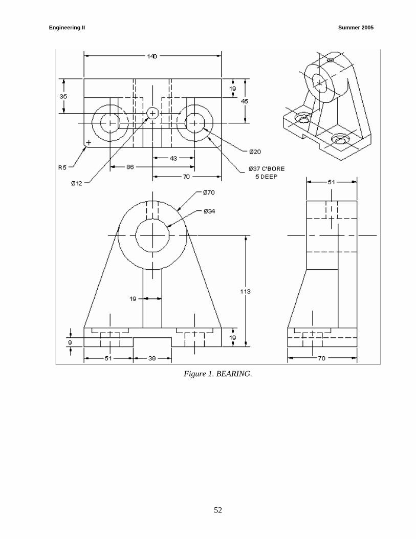
Engineering II Summer 2005
52
Figure 1. BEARING.
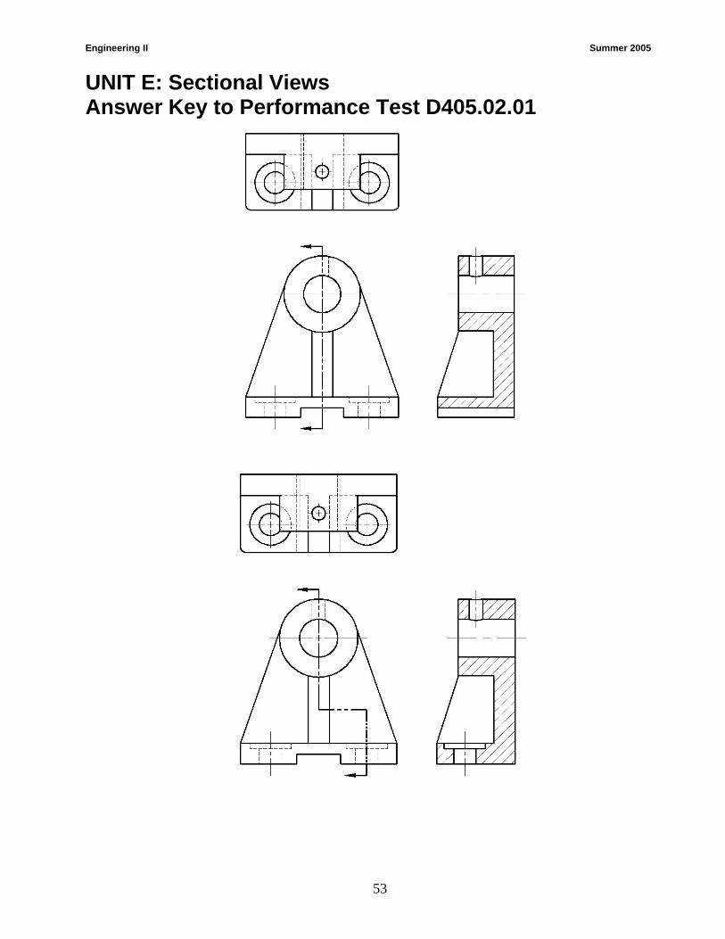
Engineering II Summer 2005
53
UNIT E: Sectional Views Answer Key to Performance Test D405.02.01
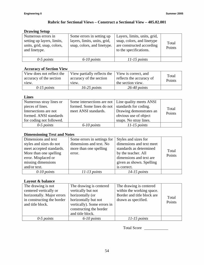
Engineering II Summer 2005
54
Rubric for Sectional Views – Construct a Sectional View – 405.02.001 Drawing Setup Numerous errors in setting up layers, limits, units, grid, snap, colors, and linetype.
Some errors in setting up layers, limits, units, grid, snap, colors, and linetype.
Layers, limits, units, grid, snap, colors, and linetype are constructed according to the specifications.
Total Points
0-5 points 6-10 points 11-15 points Accuracy of Section View View does not reflect the accuracy of the section view.
View partially reflects the accuracy of the section view.
View is correct, and reflects the accuracy of the section view.
Total Points
0-15 points 16-25 points 26-40 points Lines Numerous stray lines or pieces of lines. Intersections are not formed. ANSI standards for coding not followed.
Some intersections are not formed. Some lines do not meet ANSI standards.
Line quality meets ANSI standards for coding. Drawing demonstrates an obvious use of object snaps. No stray lines.
Total Points
0-5 points 6-10 points 11-15 points Dimensioning Text and Notes Dimensions and text styles and sizes do not meet accepted standards. More than one spelling error. Misplaced or missing dimensions and/or text.
Some errors in settings for dimensions and text. No more than one spelling error.
Styles and sizes for dimensions and text meet standards as determined by the teacher. All dimensions and text are given as shown. Spelling is correct.
Total Points
0-10 points 11-13 points 14-15 points Layout & balance The drawing is not centered vertically or horizontally. Major errors in constructing the border and title block.
The drawing is centered vertically but not horizontally (or horizontally but not vertically). Some errors in constructing the border and title block.
The drawing is centered within the working space. Border and title block are drawn as specified. Total
Points
0-5 points 6-10 points 11-15 points Total Score
Engineering II Summer 2005
55
Auxiliary Views 006. Prepare primary auxiliary views 006.01 Explain the concepts and principles of primary auxiliary views 006.02 Construct primary auxiliary views
Engineering II Summer 2005
56
UNIT F: AUXILIARY VIEWS
Competency: D406.00 Prepare primary auxiliary views.
Objective: D406.01 Explain the concepts and principles of primary auxiliary views. Introduction: The purpose of this unit is to give the student the understanding of the basic concepts of primary auxiliary views. There are times when one of the six principal views will not completely describe an object. This is especially true when there are inclined planes or features on an object. For these cases, a special orthographic view called an auxiliary view can be created. Auxiliary views are supplemental views added to a multiview drawing that contain inclined surfaces. They are used to find the edge and true shape views of inclined or angled surfaces. This unit describes how to create auxiliary views for objects that cannot be clearly represented by the six principal views. Also described is the use of auxiliary views to solve geometry problems, such as the point and true-length views of lines and edges. Instructors can take a couple of different approaches to this topic. You may elect to take the traditional 2D drawing approach where students use a 2D CAD program to construct an auxiliary view by transferring dimensions from the principal views. To better prepare students for a career in 3D modeling, require students to create a 3D solids model of the object first and then extract the multiview drawing (including the auxiliary view). Explain the following: A. Terms and their relationship to Auxiliary Views: R1(229-230); R2(316-319); R3(274-277)
1. Inclined surfaces – A surface that’s true size and shape cannot be viewed in frontal, horizontal, or profile planes.
2. True size and shape – A surface that is perpendicular to the projection plane.
3. Foreshortened surface – A surface that is not true size or not true shape.
4. Primary auxiliary views - A single view that is projected from one of the six principal views. Named according to the principal dimensions of the object shown in the auxiliary view.
5. Primary auxiliary views include:
a. Depth auxiliary – The inclined surface will appear foreshortened in a top view and a right-side view. The inclined surface will appear as a line or edge in the front view (see Figure 1).
b. Height auxiliary – The inclined surface will appear foreshortened in a front view and a right-side view. The inclined surface will appear as a line or edge in the top view (see Figure 2).
c. Width auxiliary – The inclined surface will appear foreshortened in a top view and a front view. The inclined surface will appear as a line or edge in the right or left-side view (see Figure 3).

Engineering II Summer 2005
57
Figure 1. Depth Auxiliary.
Figure 2. Height Auxiliary.
Figure 3. Width Auxiliary.
6. Reference Plane – A plane that is parallel to the inclined surfaces.
7. Auxiliary projection – An orthographic view that is drawn on any plane other than from frontal, horizontal, or profile plane.
8. Perpendicular – A surface that is perpendicular to the projection plane.

Engineering II Summer 2005
58
9. Partial auxiliary view – An auxiliary view that shows only the true size and shape of the inclined surface.
10. Line of sight "LOS"- Represents the direction you are looking at an object.
11. Reference line - Represents the intersection of two imaginary "projection planes"
12. Projection line - Shows the relationship of two views of a point.
B. Explain how to draw Primary Auxiliary Views: R1(229-217); R2(276-282); R3(136-139)
1. Auxiliary views are created by adding a "line of sight" (LOS), a "reference line" and "projection lines".
a. The "line of sight" must be perpendicular (90°) to any view of a line to find the "true length" (TL) of the line. The "line of sight" must be perpendicular (90°) to the "edge view of a surface" to find the "true shape" (TS) of the surface.
b. "Reference Lines" are drawn as a "phantom lines" (long, short, short, long) and at 90° angles to the "LOS".
c. "Projection Lines" are drawn as "dashed lines" and at 90° angles to "reference lines". Horizontal/Frontal) (Frontal/Profile) (Horizontal/Auxiliary Elevation) (Frontal/Auxiliary Inclined) and is used to measure distances from the planes to points on an object.
2. Hidden lines are typically not used in auxiliary views, unless needed for clarity. Also, a number of surfaces are not included because they are distorted and are of little value.
3. Typical steps followed to construct an auxiliary view:
a. Select the face that is to be drawn
i) A true surface
ii) A true length line
iii) An end view of a line.
b. Decide which line or surface is to be shown in an auxiliary view and which orthographic view it will be projected from. The following facts must be considered when rendering this decision:
i) Width auxiliary views are always projected from a side view.
ii) Depth auxiliary views are always projected from a front view (Figure 4).
iii) An elevation or height auxiliary view is always projected from the top view.
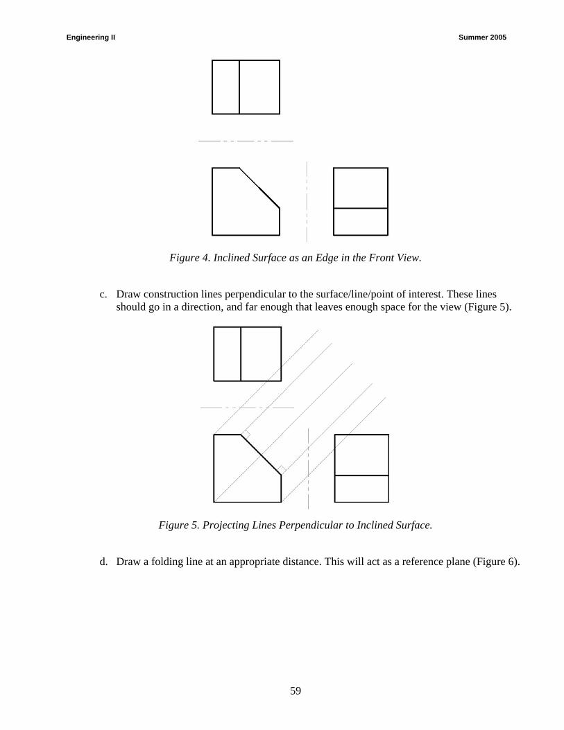
Engineering II Summer 2005
59
Figure 4. Inclined Surface as an Edge in the Front View.
c. Draw construction lines perpendicular to the surface/line/point of interest. These lines should go in a direction, and far enough that leaves enough space for the view (Figure 5).
Figure 5. Projecting Lines Perpendicular to Inclined Surface.
d. Draw a folding line at an appropriate distance. This will act as a reference plane (Figure 6).
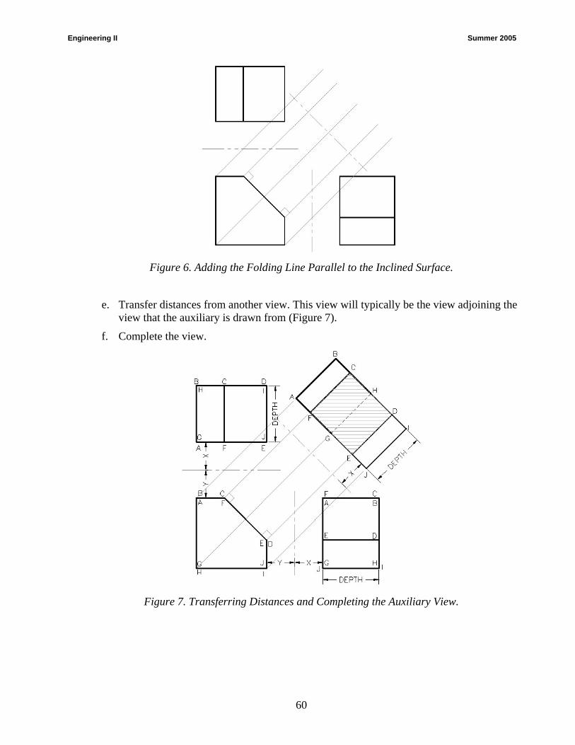
Engineering II Summer 2005
60
Figure 6. Adding the Folding Line Parallel to the Inclined Surface.
e. Transfer distances from another view. This view will typically be the view adjoining the view that the auxiliary is drawn from (Figure 7).
f. Complete the view.
Figure 7. Transferring Distances and Completing the Auxiliary View.
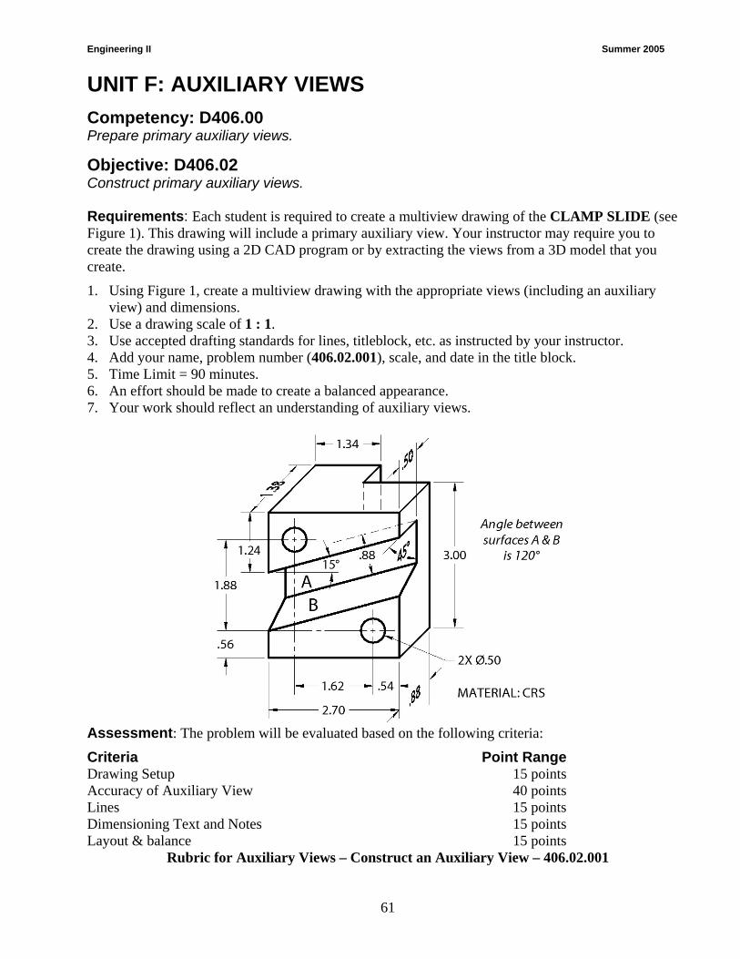
Engineering II Summer 2005
61
UNIT F: AUXILIARY VIEWS
Competency: D406.00 Prepare primary auxiliary views.
Objective: D406.02 Construct primary auxiliary views. Requirements: Each student is required to create a multiview drawing of the CLAMP SLIDE (see Figure 1). This drawing will include a primary auxiliary view. Your instructor may require you to create the drawing using a 2D CAD program or by extracting the views from a 3D model that you create.
1. Using Figure 1, create a multiview drawing with the appropriate views (including an auxiliary view) and dimensions.
2. Use a drawing scale of 1 : 1. 3. Use accepted drafting standards for lines, titleblock, etc. as instructed by your instructor. 4. Add your name, problem number (406.02.001), scale, and date in the title block. 5. Time Limit = 90 minutes. 6. An effort should be made to create a balanced appearance. 7. Your work should reflect an understanding of auxiliary views.
Assessment: The problem will be evaluated based on the following criteria:
Criteria Point Range Drawing Setup 15 points Accuracy of Auxiliary View 40 points Lines 15 points Dimensioning Text and Notes 15 points Layout & balance 15 points
Rubric for Auxiliary Views – Construct an Auxiliary View – 406.02.001
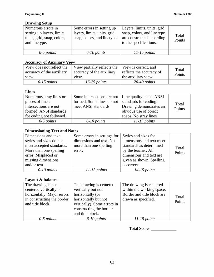
Engineering II Summer 2005
62
Drawing Setup Numerous errors in setting up layers, limits, units, grid, snap, colors, and linetype.
Some errors in setting up layers, limits, units, grid, snap, colors, and linetype.
Layers, limits, units, grid, snap, colors, and linetype are constructed according to the specifications.
Total Points
0-5 points 6-10 points 11-15 points Accuracy of Auxiliary View View does not reflect the accuracy of the auxiliary view.
View partially reflects the accuracy of the auxiliary view.
View is correct, and reflects the accuracy of the auxiliary view.
Total Points
0-15 points 16-25 points 26-40 points Lines Numerous stray lines or pieces of lines. Intersections are not formed. ANSI standards for coding not followed.
Some intersections are not formed. Some lines do not meet ANSI standards.
Line quality meets ANSI standards for coding. Drawing demonstrates an obvious use of object snaps. No stray lines.
Total Points
0-5 points 6-10 points 11-15 points Dimensioning Text and Notes Dimensions and text styles and sizes do not meet accepted standards. More than one spelling error. Misplaced or missing dimensions and/or text.
Some errors in settings for dimensions and text. No more than one spelling error.
Styles and sizes for dimensions and text meet standards as determined by the teacher. All dimensions and text are given as shown. Spelling is correct.
Total Points
0-10 points 11-13 points 14-15 points Layout & balance The drawing is not centered vertically or horizontally. Major errors in constructing the border and title block.
The drawing is centered vertically but not horizontally (or horizontally but not vertically). Some errors in constructing the border and title block.
The drawing is centered within the working space. Border and title block are drawn as specified. Total
Points
0-5 points 6-10 points 11-15 points Total Score

Engineering II Summer 2005
63
Pattern Development 007. Prepare pattern developments 007.01 Explain techniques and procedures for constructing pattern developments 007.02 Construct pattern developments

Engineering II Summer 2005
64
UNIT G: PATTERN DEVELOPMENT
Competency: D407.00 Prepare pattern developments.
Objective: D407.01 Explain techniques and procedures for constructing pattern developments. Introduction: The purpose of this unit is to give the student the understanding of the concepts related to pattern developments. This unit will help students understand how things such as car bodies, packaging, and other objects formed from flat materials are designed and manufactured.
A. Identify where patterns and developments are used: R2(507-509); R3(413-415)
1. Sheet metal industry
a. Many metal objects are made from sheet of metal that are laid out, cut, and formed into required shapes and fastened together.
i) Shaped by bending, folding, die stamping or rolling.
ii) Fastened by riveting, seaming, soldering, or welding.
b. Examples of surface developments from sheet metal would be air conditioning ducts, boxes, buckets, filing cabinets and household utensils like metal spatulas, pot and pans.
2. Packaging industry
a. Packaging is a very large industry that uses pattern development.
b. Both engineering and artistic skill are needed when creating packages, because each package design must meet many requirements.
i) To protect the contents during shipping of fragile objects.
ii) Be attractive for sales appeal.
iii) For durability—some packages are meant to be used for a short time then thrown away, others are made to last a long time.
c. Designers use many different materials and varying thickness.
i) Thin or medium –thick stock paper. This material can be folded easily for items like boxes; others may need glue on their tabs. For example: book covers, envelopes, juice cartons and paper cups.
ii) Cardboard, corrugated board and other materials require an allowance for thickness. For example: boxes that have a separate cover or boxes made of two parts that slide together.
Explain the following: B. Terms and their relationship to Pattern Developments:
1. Pattern – The development of an object that is rolled or folded.
2. surface developments -- also known as stretchouts
3. Stretchout– A flat pattern or development used in laying out, cutting and folding lines on flat stock.

Engineering II Summer 2005
65
4. Circumference – The distance around a circle. The stretchout line is equal in length to the circumference of a cylinder.
5. Truncated cylinder – A cylinder that has the end cut off by an inclined surface.
6. Parallel line development – A pattern created by drawing the edges of an object as parallel lines.
7. Radial line development – A pattern created by drawing the edges of an object radiating from a single point.
C. Create the following developments: R(575)
1. Cylinder
2. Truncated cylinder
3. Box
4. Cone
a. Create measuring lines that radiate from a single point using a radial-line development typically makes developments of pyramids and cones
b. The tip of a cone is called the apex.
c. A cone consists of planar and single-curved surfaces.
5. Pyramid
6. Truncated pyramid
7. Elbows (square, two-piece, three-piece and four-piece)
D. Creating a stretch-out line using a parallel-line development typically makes developments of prisms, cylinders and elbows.
E. The full length of a pattern when completely unfolded is represented by the stretch-out line.
F. The lines representing the location of folds or bends are called crease-lines.
G. Crease, fold or bend lines are represented by a small circle or an X.
H. A tab or lap is where additional material is added to surface developments for the purpose of assembly.
I. When two truncated prisms or cylinders meet at an angle other than 180 degrees, an elbow is formed.
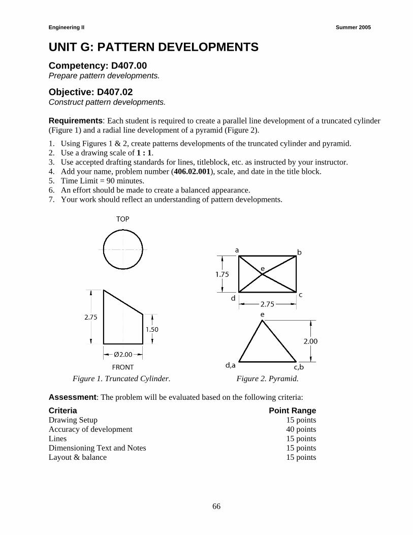
Engineering II Summer 2005
66
UNIT G: PATTERN DEVELOPMENTS
Competency: D407.00 Prepare pattern developments.
Objective: D407.02 Construct pattern developments. Requirements: Each student is required to create a parallel line development of a truncated cylinder (Figure 1) and a radial line development of a pyramid (Figure 2).
1. Using Figures 1 & 2, create patterns developments of the truncated cylinder and pyramid. 2. Use a drawing scale of 1 : 1. 3. Use accepted drafting standards for lines, titleblock, etc. as instructed by your instructor. 4. Add your name, problem number (406.02.001), scale, and date in the title block. 5. Time Limit = 90 minutes. 6. An effort should be made to create a balanced appearance. 7. Your work should reflect an understanding of pattern developments.
Figure 1. Truncated Cylinder. Figure 2. Pyramid. Assessment: The problem will be evaluated based on the following criteria:
Criteria Point Range Drawing Setup 15 points Accuracy of development 40 points Lines 15 points Dimensioning Text and Notes 15 points Layout & balance 15 points

Engineering II Summer 2005
67
Rubric for Pattern Developments – Construct an Pattern Developments – 407.02.001 Drawing Setup Numerous errors in setting up layers, limits, units, grid, snap, colors, and linetype.
Some errors in setting up layers, limits, units, grid, snap, colors, and linetype.
Layers, limits, units, grid, snap, colors, and linetype are constructed according to the specifications.
Total Points
0-5 points 6-10 points 11-15 points Accuracy of Pattern Developments Views do not reflect the accuracy of the development.
Views partially reflect the accuracy of the development.
Views are correct, and reflect the accuracy of the development.
Total Points
0-15 points 16-25 points 26-40 points Lines Numerous stray lines or pieces of lines. Intersections are not formed. ANSI standards for coding not followed.
Some intersections are not formed. Some lines do not meet ANSI standards.
Line quality meets ANSI standards for coding. Drawing demonstrates an obvious use of object snaps. No stray lines.
Total Points
0-5 points 6-10 points 11-15 points Dimensioning Text and Notes Dimensions and text styles and sizes do not meet accepted standards. More than one spelling error. Misplaced or missing dimensions and/or text.
Some errors in settings for dimensions and text. No more than one spelling error.
Styles and sizes for dimensions and text meet standards as determined by the teacher. All dimensions and text are given as shown. Spelling is correct.
Total Points
0-10 points 11-13 points 14-15 points Layout & balance The drawing is not centered vertically or horizontally. Major errors in constructing the border and title block.
The drawing is centered vertically but not horizontally (or horizontally but not vertically). Some errors in constructing the border and title block.
The drawing is centered within the working space. Border and title block are drawn as specified. Total
Points
0-5 points 6-10 points 11-15 points Total Score

APPENDIX A Bibliography / References
Textbooks
Reference 1: Giesecke, F. E., Mitchell, A., Spencer, H. C., Hill, I. L., Dygdon, J. T., & Novak, J. E. (2003). Technical drawing (12th ed.).Upper Saddle River, NJ: Prentice-Hall. ISBN: 0-13-008183-3.
Reference 2: French, T. E. & Hensel, J. D. (2003) Mechanical drawing: Board & CAD techniques (13th ed.). New York: Glencoe/McGraw-Hill. ISBN: 0-07-825100-1.
Reference 3: Spencer, H. C., Dygdon, J. T., & Novak, J. E. (2004). Basic technical drawing (8th ed.). New York: Glencoe/McGraw-Hill. ISBN: 0-07-845748-3.
Reference 4: Madsen, D. A, Folkestad, J., Schertz, K. A, Shumaker, T. M., Stark, C. & Turpin, J. L. (2004). Engineering drawing and design (3rd ed.). Albany, NY: Delmar. ISBN: 0-7668-1634-6.
CAD Software Websites
AutoCAD-LT, AutoCAD, and Inventor – www.autodesk.com
CADKEY – www.cadkey.com
Pro/Engineering & Pro/Desktop – www.ptc.com
Solid Edge – www.solid-edge.com
SolidWorks – www.solidworks.com
Student Version Pricing for CAD Software – www.journeyed.com
68

APPENDIX B
Vendor’s – Texts – Software – Literature
Software Autodesk Products (ie AutoCAD 2006) Kris Dell ADADemic/Applied Software 3200 Northline Ave, Suite 130 Greensboro, NC 27403 Phone: 704-491-2285 Fax: 704-573-9981 [email protected] ProDesktop PTC Offices-Charlotte 2201 Water Ridge Pkwy Suite 550 Charlotte, NC 28217 Phone: 704-357-3170 Fax: 704-357-6011 www.ptc.com SolidWorks Joe Wilkie SolidWorks Corporation 3112 Stone Gap Court Raleigh, NC 27612 Phone: 919-781-7304 Fax: 928-569-5640 [email protected]
Vendor’s – Texts Amazon.com, Inc. (Book resource) www.amazon.com Glencoe/McGraw-Hill Pam Angotti 6510 Jimmy Carter Boulevard Norcross, GA 30071 Phone: 919-469-4517 Fax: 770-613-5065 [email protected] Goodheart-Willcox Publishing Liz Myhre 18604 West Creek Drive Tinley Park, IL 60477 Phone: 800-365-3907 Fax: 919-468-3792 [email protected] Thomson Publishing Patrick Delaney 7813 Waterford Ridge Dr. #702 Charlotte, NC 28212 Phone: 877-430-0483 [email protected]
69

NC-DPI Tom Shown Department of Public Instruction Instruction Technology & Human Services 6360 Mail Service Center Raleigh, NC 27699-6360 Phone: 919-807-3880 Fax: 919-807-3899 [email protected]
NC SkillsUSA VICA Glen Barefoot Department of Public Instruction Instruction Technology & Human Services 6360 Mail Service Center Raleigh, NC 27699-6360 Phone: 919-807-3887 Fax: 919-807-3899 [email protected] National SkillsUSA VICA P.O. Box 3000 Leesburg, VA 20177-0300 Phone: 703-777-8810 Fax: 703-777-8999 www.vica.org
70
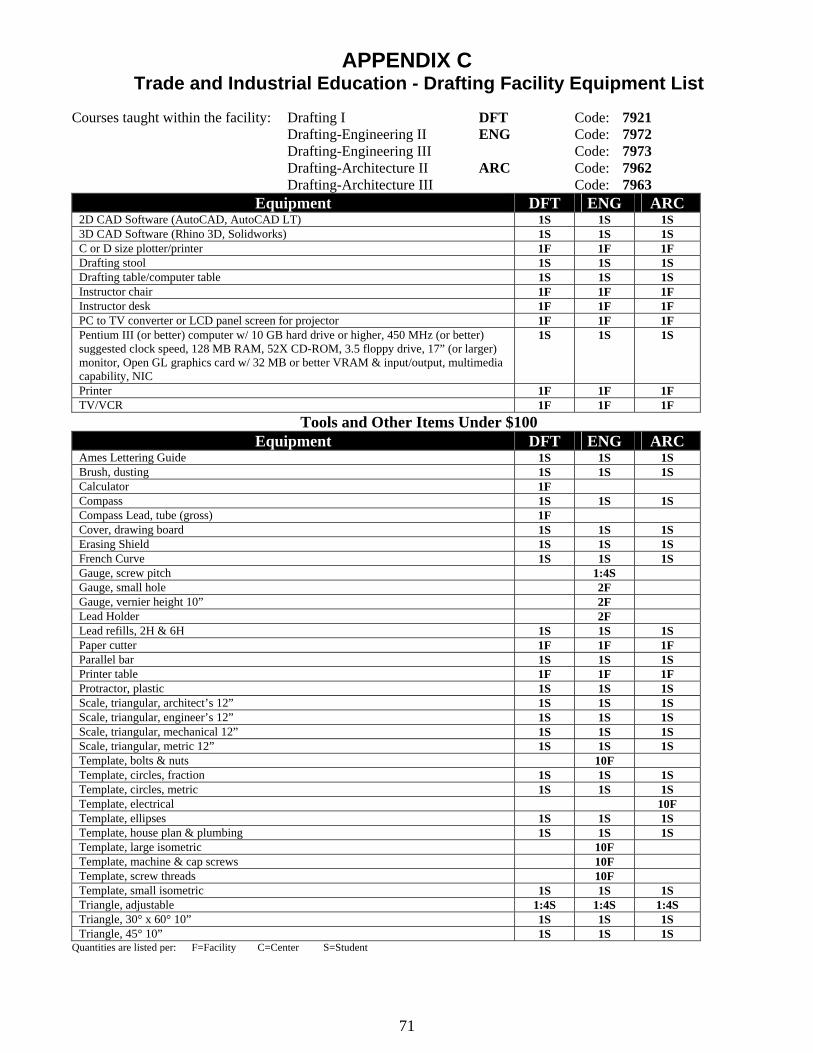
APPENDIX C Trade and Industrial Education - Drafting Facility Equipment List
Courses taught within the facility: Drafting I DFT Code: 7921
Drafting-Engineering II ENG Code: 7972 Drafting-Engineering III Code: 7973 Drafting-Architecture II ARC Code: 7962 Drafting-Architecture III Code: 7963
Equipment DFT ENG ARC 2D CAD Software (AutoCAD, AutoCAD LT) 1S 1S 1S 3D CAD Software (Rhino 3D, Solidworks) 1S 1S 1S C or D size plotter/printer 1F 1F 1F Drafting stool 1S 1S 1S Drafting table/computer table 1S 1S 1S Instructor chair 1F 1F 1F Instructor desk 1F 1F 1F PC to TV converter or LCD panel screen for projector 1F 1F 1F Pentium III (or better) computer w/ 10 GB hard drive or higher, 450 MHz (or better) suggested clock speed, 128 MB RAM, 52X CD-ROM, 3.5 floppy drive, 17” (or larger) monitor, Open GL graphics card w/ 32 MB or better VRAM & input/output, multimedia capability, NIC
1S 1S 1S
Printer 1F 1F 1F TV/VCR 1F 1F 1F
Tools and Other Items Under $100 Equipment DFT ENG ARC
Ames Lettering Guide 1S 1S 1S Brush, dusting 1S 1S 1S Calculator 1F Compass 1S 1S 1S Compass Lead, tube (gross) 1F Cover, drawing board 1S 1S 1S Erasing Shield 1S 1S 1S French Curve 1S 1S 1S Gauge, screw pitch 1:4S Gauge, small hole 2F Gauge, vernier height 10” 2F Lead Holder 2F Lead refills, 2H & 6H 1S 1S 1S Paper cutter 1F 1F 1F Parallel bar 1S 1S 1S Printer table 1F 1F 1F Protractor, plastic 1S 1S 1S Scale, triangular, architect’s 12” 1S 1S 1S Scale, triangular, engineer’s 12” 1S 1S 1S Scale, triangular, mechanical 12” 1S 1S 1S Scale, triangular, metric 12” 1S 1S 1S Template, bolts & nuts 10F Template, circles, fraction 1S 1S 1S Template, circles, metric 1S 1S 1S Template, electrical 10F Template, ellipses 1S 1S 1S Template, house plan & plumbing 1S 1S 1S Template, large isometric 10F Template, machine & cap screws 10F Template, screw threads 10F Template, small isometric 1S 1S 1S Triangle, adjustable 1:4S 1:4S 1:4S Triangle, 30° x 60° 10” 1S 1S 1S Triangle, 45° 10” 1S 1S 1S
Quantities are listed per: F=Facility C=Center S=Student
71
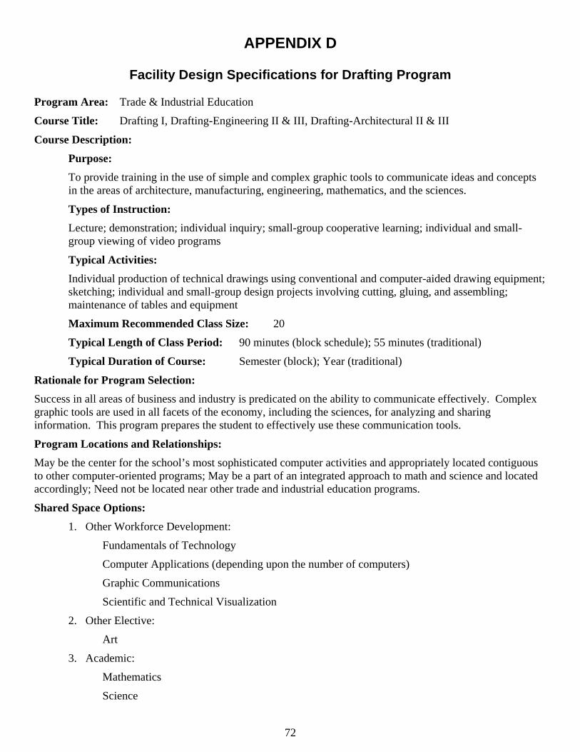
APPENDIX D
Facility Design Specifications for Drafting Program
Program Area: Trade & Industrial Education
Course Title: Drafting I, Drafting-Engineering II & III, Drafting-Architectural II & III
Course Description:
Purpose: To provide training in the use of simple and complex graphic tools to communicate ideas and concepts in the areas of architecture, manufacturing, engineering, mathematics, and the sciences.
Types of Instruction: Lecture; demonstration; individual inquiry; small-group cooperative learning; individual and small-group viewing of video programs
Typical Activities: Individual production of technical drawings using conventional and computer-aided drawing equipment; sketching; individual and small-group design projects involving cutting, gluing, and assembling; maintenance of tables and equipment
Maximum Recommended Class Size: 20
Typical Length of Class Period: 90 minutes (block schedule); 55 minutes (traditional)
Typical Duration of Course: Semester (block); Year (traditional)
Rationale for Program Selection: Success in all areas of business and industry is predicated on the ability to communicate effectively. Complex graphic tools are used in all facets of the economy, including the sciences, for analyzing and sharing information. This program prepares the student to effectively use these communication tools.
Program Locations and Relationships: May be the center for the school’s most sophisticated computer activities and appropriately located contiguous to other computer-oriented programs; May be a part of an integrated approach to math and science and located accordingly; Need not be located near other trade and industrial education programs.
Shared Space Options: 1. Other Workforce Development:
Fundamentals of Technology
Computer Applications (depending upon the number of computers)
Graphic Communications
Scientific and Technical Visualization
2. Other Elective:
Art
3. Academic:
Mathematics
Science
72
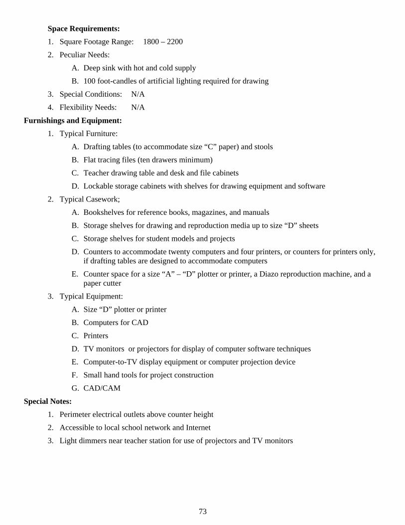
Space Requirements: 1. Square Footage Range: 1800 – 2200
2. Peculiar Needs:
A. Deep sink with hot and cold supply
B. 100 foot-candles of artificial lighting required for drawing
3. Special Conditions: N/A
4. Flexibility Needs: N/A
Furnishings and Equipment: 1. Typical Furniture:
A. Drafting tables (to accommodate size “C” paper) and stools
B. Flat tracing files (ten drawers minimum)
C. Teacher drawing table and desk and file cabinets
D. Lockable storage cabinets with shelves for drawing equipment and software
2. Typical Casework;
A. Bookshelves for reference books, magazines, and manuals
B. Storage shelves for drawing and reproduction media up to size “D” sheets
C. Storage shelves for student models and projects
D. Counters to accommodate twenty computers and four printers, or counters for printers only, if drafting tables are designed to accommodate computers
E. Counter space for a size “A” – “D” plotter or printer, a Diazo reproduction machine, and a paper cutter
3. Typical Equipment:
A. Size “D” plotter or printer
B. Computers for CAD
C. Printers
D. TV monitors or projectors for display of computer software techniques
E. Computer-to-TV display equipment or computer projection device
F. Small hand tools for project construction
G. CAD/CAM
Special Notes: 1. Perimeter electrical outlets above counter height
2. Accessible to local school network and Internet
3. Light dimmers near teacher station for use of projectors and TV monitors
73
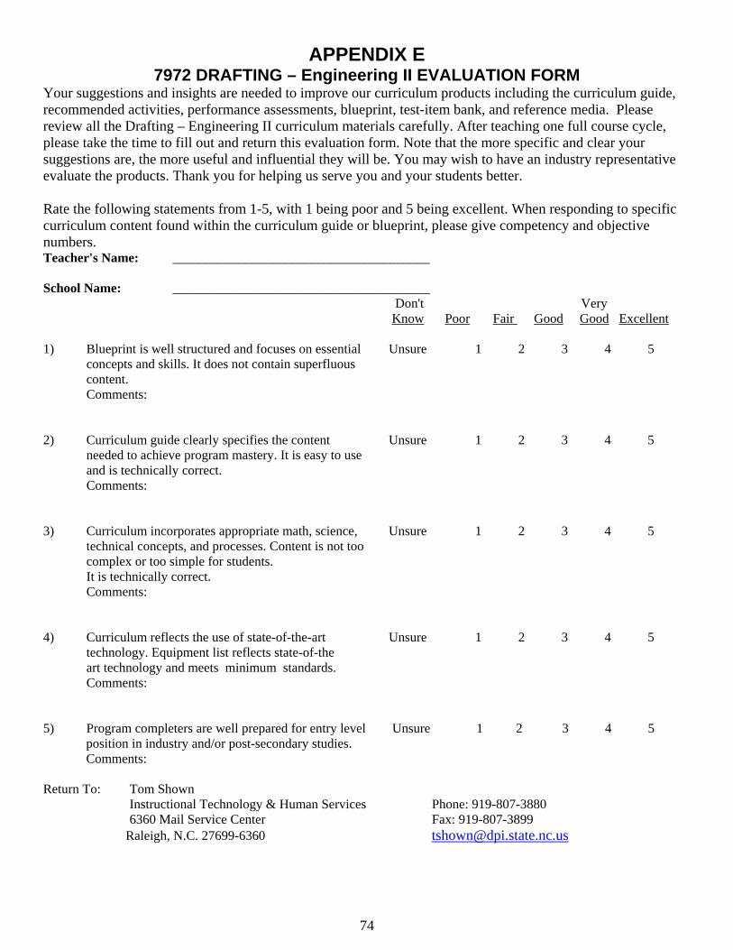
APPENDIX E 7972 DRAFTING – Engineering II EVALUATION FORM
Your suggestions and insights are needed to improve our curriculum products including the curriculum guide, recommended activities, performance assessments, blueprint, test-item bank, and reference media. Please review all the Drafting – Engineering II curriculum materials carefully. After teaching one full course cycle, please take the time to fill out and return this evaluation form. Note that the more specific and clear your suggestions are, the more useful and influential they will be. You may wish to have an industry representative evaluate the products. Thank you for helping us serve you and your students better. Rate the following statements from 1-5, with 1 being poor and 5 being excellent. When responding to specific curriculum content found within the curriculum guide or blueprint, please give competency and objective numbers. Teacher's Name: _______________________________________ School Name: _______________________________________
Don't Very Know Poor Fair Good Good Excellent
1) Blueprint is well structured and focuses on essential Unsure 1 2 3 4 5 concepts and skills. It does not contain superfluous content. Comments:
2) Curriculum guide clearly specifies the content Unsure 1 2 3 4 5 needed to achieve program mastery. It is easy to use and is technically correct. Comments:
3) Curriculum incorporates appropriate math, science, Unsure 1 2 3 4 5
technical concepts, and processes. Content is not too complex or too simple for students. It is technically correct. Comments:
4) Curriculum reflects the use of state-of-the-art Unsure 1 2 3 4 5
technology. Equipment list reflects state-of-the art technology and meets minimum standards. Comments:
5) Program completers are well prepared for entry level Unsure 1 2 3 4 5 position in industry and/or post-secondary studies. Comments:
Return To: Tom Shown
Instructional Technology & Human Services Phone: 919-807-3880 6360 Mail Service Center Fax: 919-807-3899
Raleigh, N.C. 27699-6360 [email protected]
74