7g precast and prestressed slabs.pdf
TRANSCRIPT

8/13/2019 7G Precast and Prestressed Slabs.pdf
http://slidepdf.com/reader/full/7g-precast-and-prestressed-slabspdf 1/12
7.7-i
Table of Contents
Section 7 ..................................................................................................................................................
Inspection and
Evaluation of
Common ConcreteSuperstructures
7.7 Precast and Prestressed Slabs.................................................................7.7.1
7.7.1 Introduction............................................................................... 7.7.1
7.7.2 Design Characteristics............................................................... 7.7.1
General.............................................................................. 7.7.1Monolithic Behavior......................................................... 7.7.2
Identifying Voided Slabs .................................................. 7.7.2Primary and Secondary Members..................................... 7.7.2
Steel Reinforcement.......................................................... 7.7.2Primary Reinforcement ..............................................7.7.2Secondary Reinforcement .......................................... 7.7.3
7.7.3 Overview of Common Defects ................................................. 7.7.3
7.7.4 Inspection Procedures and Locations........................................ 7.7.4Procedures.........................................................................7.7.4
Visual .........................................................................7.7.4Physical ...................................................................... 7.7.4
Advanced Inspection Techniques............................... 7.7.4Locations...........................................................................7.7.5
Bearing Areas.............................................................7.7.5Shear Zones................................................................ 7.7.5Tension Zones ............................................................ 7.7.6
Areas Exposed to Drainage........................................ 7.7.7Areas Exposed to Traffic............................................7.7.7Areas Previously Repaired......................................... 7.7.7
General ....................................................................... 7.7.8

8/13/2019 7G Precast and Prestressed Slabs.pdf
http://slidepdf.com/reader/full/7g-precast-and-prestressed-slabspdf 2/12
SECTION 7: Inspection and Evaluation of Common Concrete Superstructures
TOPIC 7.7: Precast and Prestressed Slabs
7.7-ii
7.7.5 Evaluation.................................................................................7.7.8
NBI Rating Guidelines......................................................7.7.8Element Level Condition State Assessment ..................... 7.7.8

8/13/2019 7G Precast and Prestressed Slabs.pdf
http://slidepdf.com/reader/full/7g-precast-and-prestressed-slabspdf 3/12
8/13/2019 7G Precast and Prestressed Slabs.pdf
http://slidepdf.com/reader/full/7g-precast-and-prestressed-slabspdf 4/12
SECTION 7: Inspection and Evaluation of Common Concrete Superstructures
TOPIC 7.7: Precast and Prestressed Slabs
7.7.2
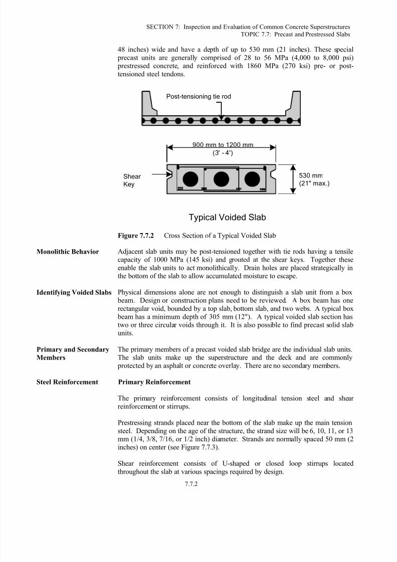
48 inches) wide and have a depth of up to 530 mm (21 inches). These special
precast units are generally comprised of 28 to 56 MPa (4,000 to 8,000 psi) prestressed concrete, and reinforced with 1860 MPa (270 ksi) pre- or post-
tensioned steel tendons.
900mmto1200mm
(3'- 4')
Shear
Key
530mm
(21"max.)
TypicalVoidedSlab
Post-tensioningtierod
Figure 7.7.2 Cross Section of a Typical Voided Slab
Monolithic Behavior Adjacent slab units may be post-tensioned together with tie rods having a tensilecapacity of 1000 MPa (145 ksi) and grouted at the shear keys. Together these
enable the slab units to act monolithically. Drain holes are placed strategically inthe bottom of the slab to allow accumulated moisture to escape.
Identifying Voided Slabs Physical dimensions alone are not enough to distinguish a slab unit from a box beam. Design or construction plans need to be reviewed. A box beam has one
rectangular void, bounded by a top slab, bottom slab, and two webs. A typical box beam has a minimum depth of 305 mm (12"). A typical voided slab section hastwo or three circular voids through it. It is also possible to find precast solid slabunits.
Primary and Secondary
Members
The primary members of a precast voided slab bridge are the individual slab units.The slab units make up the superstructure and the deck and are commonly
protected by an asphalt or concrete overlay. There are no secondary members.
Steel Reinforcement Primary Reinforcement
The primary reinforcement consists of longitudinal tension steel and shearreinforcement or stirrups.
Prestressing strands placed near the bottom of the slab make up the main tension
steel. Depending on the age of the structure, the strand size will be 6, 10, 11, or 13mm (1/4, 3/8, 7/16, or 1/2 inch) diameter. Strands are normally spaced 50 mm (2inches) on center (see Figure 7.7.3).
Shear reinforcement consists of U-shaped or closed loop stirrups located
throughout the slab at various spacings required by design.

8/13/2019 7G Precast and Prestressed Slabs.pdf
http://slidepdf.com/reader/full/7g-precast-and-prestressed-slabspdf 5/12
SECTION 7: Inspection and Evaluation of Common Concrete Superstructures
TOPIC 7.7: Precast and Prestressed Slabs
7.7.3
Secondary Reinforcement
Secondary reinforcement is provided to control temperature and shrinkagecracking. This reinforcement is placed longitudinal in the beam.
Temperatureand
shrinkagesteel
Stirrups
Highstrength
steelstrandsorreinforcementbars
Figure 7.7.3 Prestressed Slab Beam Bridge Reinforcement
7.7.3
Overview of
Common Defects
Common defects that occur on precast and prestressed slab bridges include:
Cracking (flexure, shear, temperature, shrinkage, mass concrete)
Scaling
Delamination
Spalling
Chloride contamination
Efflorescence
Ettringite formation
Honeycombs
Pop-outs
Wear
Collision damage
Abrasion
Overload damage
Reinforcing steel corrosion
Prestressed concrete deterioration
Stress corrosion
Refer to Topic 2.2 for a detailed presentation of the properties of concrete, types
and causes of concrete deterioration, and the examination of concrete.

8/13/2019 7G Precast and Prestressed Slabs.pdf
http://slidepdf.com/reader/full/7g-precast-and-prestressed-slabspdf 6/12
SECTION 7: Inspection and Evaluation of Common Concrete Superstructures
TOPIC 7.7: Precast and Prestressed Slabs
7.7.4
7.7.4
Inspection
Procedures and
Locations
Inspection procedures to determine other causes of concrete deterioration arediscussed in detail in Topic 2.2.8.
Procedures Visual
The inspection of concrete slabs for cracks, spalls, wear, and other defects is primarily a visual activity.
Physical
The physical examination of the top surface of the slab with a hammer can be atedious operation. In most cases, a chain drag is used to determine delaminatedareas. A chain drag is made of several sections of chain attached to a pipe that hasa handle attached to it. The inspector drags this across a slab and makes note of
the resonating sounds. A delaminated area will have a distinctive hollow
“clacking” sound when tapped with a hammer or revealed with a chain drag. Ahammer hitting sound concrete will result in a solid “pinging” type sound.
Since prestressed beams are designed to maintain all concrete in compression,
cracks are indications of serious problems. For this reason, any crack should becarefully measured with an optical crack gauge or crack comparator card anddocumented.
Advanced Inspection Techniques
Several advanced techniques are available for concrete inspection. Nondestructivemethods, described in Topic 13.2.2, include:
Acoustic wave sonic/ultrasonic velocity measurements
Delamination detection machinery
Electrical methods
Electromagnetic methods
Pulse velocity
Flat jack testing
Ground-penetrating radar
Impact-echo testing
Infrared thermography
Laser ultrasonic testing
Magnetic field disturbance
Neutron probe for detection of chlorides
Nuclear methods
Pachometer
Rebound and penetration methods
Ultrasonic testing
Other methods, described in Topic 13.2.3, include:

8/13/2019 7G Precast and Prestressed Slabs.pdf
http://slidepdf.com/reader/full/7g-precast-and-prestressed-slabspdf 7/12
SECTION 7: Inspection and Evaluation of Common Concrete Superstructures
TOPIC 7.7: Precast and Prestressed Slabs
7.7.5
Core sampling
Carbonation
Concrete permeability
Concrete strength
Endoscopes and videoscopes
Moisture content Petrographic examination
Reinforcing steel strength
Chloride test
Matrix analysis
ASR evaluation
Locations Bearing Areas
Examine the bearing areas for cracking, delamination or spalling where thermalmovement and high bearing pressure could overstress the concrete. End spalling
can eventually lead to the loss of bond in the prestressing tendons. Bearing areasshould also be checked for defects or deterioration due to leaking joints.
Check bearing areas for spalls or vertical cracks. Spalls and cracks may be caused by corrosion of steel due to water leakage or restriction of thermal movement dueto a faulty bearing mechanism.
Shear Zones
Inspect near the supports for diagonal or shear cracks.
Inspect the top surface for longitudinal reflective cracking and between the slab
sections for leakage (see Figure 7.7.4). These problems indicate failed shear keysand that the slab units are no longer tied together or acting monolithically.Observe if there is differential slab deflection under live load.

8/13/2019 7G Precast and Prestressed Slabs.pdf
http://slidepdf.com/reader/full/7g-precast-and-prestressed-slabspdf 8/12
SECTION 7: Inspection and Evaluation of Common Concrete Superstructures
TOPIC 7.7: Precast and Prestressed Slabs
7.7.6
Figure 7.7.4 Leaking Joint between Adjacent Slab Units
Tension Zones
Check the bottom of the slab sections for flexure cracks due to positive moments.Since prestressed concrete is under high compressive forces, no cracks should be
present. Cracks can be a serious problem since they indicate overloading or loss of prestress. Cracks that may be present will be difficult to detect with the naked eye.
To improve detection, a common practice is to wet the slab surface with waterusing a spray bottle. Capillary action will draw water into a crack, thus producinga visible line when the surrounding surface water evaporates. All cracks should be
measured with an optical crack gauge or crack comparator card.
Examine the top of the slab sections (if exposed) near the ends for tensile cracksdue to prestress eccentricity. This indicates excessive prestress force. If the top ofthe slab has a wearing surface applied, check for cracks in the wearing surface.Cracks in the wearing surface may be an indication that the slab is overstressed orthat water is getting to the slab.
Investigate for evidence of sagging, which indicates a loss of prestress. Use astring line or site down the bottom edge of the fascia slab.
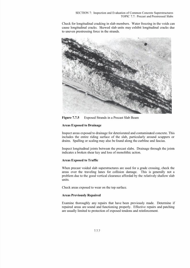
Inspect the slabs for exposed strands. Prestressed strands will corrode rapidly and
fail abruptly. Therefore, any exposure is significant (see Figure 7.7.5).
8/13/2019 7G Precast and Prestressed Slabs.pdf
http://slidepdf.com/reader/full/7g-precast-and-prestressed-slabspdf 9/12
SECTION 7: Inspection and Evaluation of Common Concrete Superstructures
TOPIC 7.7: Precast and Prestressed Slabs
7.7.7
Check for longitudinal cracking in slab members. Water freezing in the voids can
cause longitudinal cracks. Skewed slab units may exhibit longitudinal cracks dueto uneven prestressing force in the strands.
Figure 7.7.5 Exposed Strands in a Precast Slab Beam
Areas Exposed to Drainage
Inspect areas exposed to drainage for deteriorated and contaminated concrete. Thisincludes the entire riding surface of the slab, particularly around scuppers or
drains. Spalling or scaling may also be found along the curbline and fascias.
Inspect longitudinal joints between the precast slabs. Drainage through the jointsindicates a broken shear key and loss of monolithic action.
Areas Exposed to Traffic
When precast voided slab superstructures are used for a grade crossing, check theareas over the traveling lanes for collision damage. This is generally not a
problem due to the good vertical clearance afforded by the relatively shallow slabunits.
Check areas exposed to wear on the top surface.
Areas Previously Repaired
Examine thoroughly any repairs that have been previously made. Determine ifrepaired areas are sound and functioning properly. Effective repairs and patchingare usually limited to protection of exposed tendons and reinforcement.
8/13/2019 7G Precast and Prestressed Slabs.pdf
http://slidepdf.com/reader/full/7g-precast-and-prestressed-slabspdf 10/12
SECTION 7: Inspection and Evaluation of Common Concrete Superstructures
TOPIC 7.7: Precast and Prestressed Slabs
7.7.8
General
Check the camber of the slab units. Loss of positive camber indicates loss of
prestress in the tendons.
Check the condition of the lateral post-tensioning grout pockets. Cracked grout orrust stains may indicate a failure of the post-tensioning tendon or loss ofmonolithic action.
7.7.5
Evaluation State and federal rating guideline systems have been developed to aid in the
inspection of concrete superstructures. The two major rating guideline systemscurrently in use are the FHWA's Recording and Coding Guide for the Structural
Inventory and Appraisal of the Nation's Bridges used for the National BridgeInventory (NBI) component rating method and the AASHTO element levelcondition state assessment method.
NBI Rating Guidelines Using NBI rating guidelines, a 1-digit code on the Federal Structure Inventory andAppraisal (SI&A) sheet indicates the condition of the deck and the superstructure.Rating codes range from 9 to 0, where 9 is the best rating possible. See Topic 4.2
(Items 58 and 59) for additional details about NBI Rating Guidelines. For a precast or prestressed slab bridge, these guidelines must be applied for both thedeck component and the superstructure component.
The previous inspection data should be considered along with current inspection
findings to determine the correct rating.
Typically, for this type of structure, the deck and superstructure components willhave the same rating.
Element Level Condition
State Assessment
In an element level condition state assessment of a precast or prestressed slab bridge, the AASHTO CoRe element is one of the following depending on theriding surface:
Element No. Description
Concrete Slab38 Concrete Slab – Bare
39 Concrete Slab – Unprotected with AC Overlay40 Concrete Slab – Protected with AC Overlay
44 Concrete Slab – Protected with Thin Overlay48 Concrete Slab – Protected with Rigid Overlay
52 Concrete Slab – Protected with Coated Bars53 Concrete Slab – Protected with Cathodic System
P/S Box Girder
104 P/S Closed Web/Box Girder
The unit quantity for the slab elements is “each”, and the entire element must be placed in one of the five available condition states based solely on the top surface
condition. Some states have elected to use the total slab area (m² or ft²). When atotal area is used, the total area must be distributed among the five availablecondition states depending on the extent and severity of deterioration. The sum of

8/13/2019 7G Precast and Prestressed Slabs.pdf
http://slidepdf.com/reader/full/7g-precast-and-prestressed-slabspdf 11/12
SECTION 7: Inspection and Evaluation of Common Concrete Superstructures
TOPIC 7.7: Precast and Prestressed Slabs
7.7.9
all condition states must equal the total quantity of the CoRe element. The
inspector must know the total slab surface area in order to calculate a percentdeterioration and fit into a given condition state description. The unit quantity for
the girder is meters or feet, and the total length must be distributed among theavailable condition states depending on the extent and severity of deterioration.Element 104 is the closest choice in the AASHTO element list for
precast/prestressed slabs. Condition state 1 is the best possible rating. See the AASHTO Guide for Commonly Recognized (CoRe) Structural Elements for
condition state descriptions. States may decide to choose their own elementnumber for precast/prestressed slabs because AASHTO does not have a specificelement number for prestressed slabs.
A Smart Flag is used when a specific condition exists, which is not described in
the CoRe element condition state. The severity of the damage is captured bycoding the appropriate Smart Flag condition state. The Smart Flag quantities aremeasured as each, with only one each of any given Smart Flag per bridge.
For structural cracks in the top surface of bare slabs, the “Deck Cracking” Smart
Flag, Element No. 358, can be used and one of four condition states assigned. Donot use Smart Flag, Element No. 358, if the bridge deck/slab has any overlay
because the top surface of the structural deck is not visible. For concrete defectson the underside of a slab element, the “Soffit” Smart Flag, Element No. 359, can
be used and one of five condition states assigned.

8/13/2019 7G Precast and Prestressed Slabs.pdf
http://slidepdf.com/reader/full/7g-precast-and-prestressed-slabspdf 12/12
SECTION 7: Inspection and Evaluation of Common Concrete Superstructures
TOPIC 7.7: Precast and Prestressed Slabs
7.7.10
This page intentionally left blank.