8. maintenance · used to remove ash. gently tap the flue pipe and allow ash to fall into the heat...
TRANSCRIPT

8. Maintenance Regular maintenance is required to keep your EnergyLogic furnace operating reliably and efficiently. For best results, purchase an EnergyLogic furnace annual maintenance kit (PN 05000027 for EL140/200 or 05000028 for EL350), which includes nozzle, preheater/drip cap/burner/solenoid gaskets and o-rings, as well as fuel and air compressor filters. An EnergyLogic burner maintenance brush kit (PN 05000071) and an EnergyLogic furnace cleaning tool are the best tools to use with the maintenance procedures.
Clean preheater and replace gaskets annually.
Clean / inspect solenoid valve and replace o-ring annually.
Clean / inspect nozzle and flame retention head and replace nozzle or o-ring annually.
Compressor maintenance annually
Ash removal every 800 – 1000 hrs.
Clean Blower Wheel every 800 – 1000 hrs.
Ash removal every 800 – 1000 hrs.
Drain water from tank as needed. Clean tank as needed. Inspect monthly. Check local codes.
Replace fuel filter at least every 800 -1000 hrs.
Inspect and adjust electrode and retention head settings annually.
43
Call 1-615-471-5290 for Technical Support

8.1 Service Contracts If you are not qualified or do not wish to perform the furnace maintenance yourself, contact EnergyLogic for the location of our nearest dealer or service provider. Putting a service contract in place is the best way to make sure that the required maintenance is completed regularly and your system will operate reliably when needed, saving you both time and money.
8.2 Safety Warnings – Lockout/Tagout There are many potential hazards associated with working on this equipment, including electricity, heat, heights, dust and chemicals. Make sure the main electrical circuit is off and locked out / tagged out prior to performing maintenance. Wear proper safety equipment for the tasks, including a HEPA quality dust mask to avoid inhalation of ash dust when cleaning the heat exchanger or flue. Use suitable access aids/equipment when working on the furnace. Do not climb on the furnace. General safety rules and precautions should be followed at all times to prevent any accidents that could lead to personal injury or property damage. Only those qualified should perform these tasks.
8.3 Monitoring System Performance over Time EnergyLogic recommends that you monitor and record your system gauge readings regularly over time, in order to diagnose issues that may arise. For example, if the pump vacuum gauge initially read 2 inches Hg, but over time has risen to 10 inches Hg, it is an indication that the fuel filter is most likely clogged up. Record the system gauge readings on your maintenance schedule and log. Have this log handy if you call EnergyLogic for technical support.
8.4 Maintenance Schedule and Parts The recommended maintenance interval and log is shown on the following page. Check your local codes and regulations for maintenance frequency requirements that may take precedence. Use of certain fuels or other conditions may require more frequent maintenance. Make a copy of the maintenance log and use it to record the maintenance and system performance readings over time. Contact your EnergyLogic dealer or call EnergyLogic for service parts. EnergyLogic offers convenient annual maintenance kits and cleaning tools made specifically for your furnace. Economical bulk packs of fuel and air filters are available as well.
The maintenance schedule is the minimum recommended, but if you see smoke or have trip outs then the unit must be shut down and serviced immediately before running it again. Increase the maintenance as your situation requires.
44
Call 1-615-471-5290 for Technical Support

45
Call 1-615-471-5290 for Technical Support
8.5 Maintenance Procedures The following sections provide detail on how to perform the recommended maintenance. If you have questions or need assistance, contact EnergyLogic Technical Service.
8.5.1 Heat Exchanger Cleaning
How often? Clean ash from heat exchanger once every 800 to 1,000 hours of operation (or if there are signs of incomplete combustion or smoke). Or, to remove accumulated oil as needed.
Tools Required: 5/16 in. & 1/2 in. sockets, 3/4 in. open-ended wrench, EnergyLogic Furnace Cleaning Tool (PN 14033227 for the EL-140H and EL-200H; PN 04000223 for the EL-350H), chimney brush, small pipe brush, work gloves, dust mask and safety glasses, large heavy-duty plastic trash bag and duct tape. For your convenience, EnergyLogic offers flue brush accessories.
Personally verify that the main power is turned off and locked out at the circuit breaker.
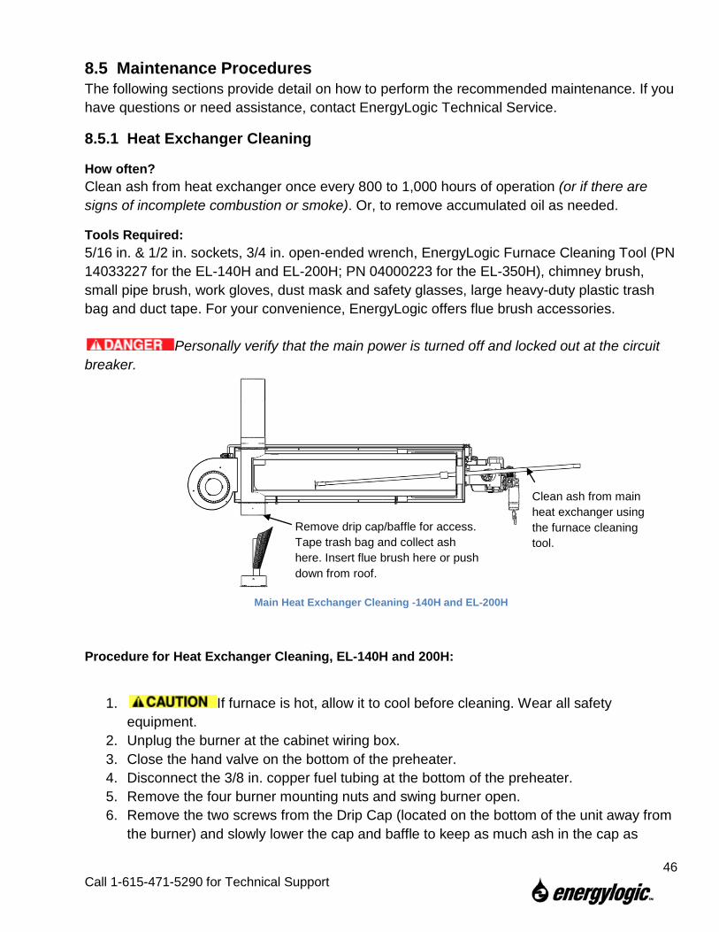
Main Heat Exchanger Cleaning -140H and EL-200H
Procedure for Heat Exchanger Cleaning, EL-140H and 200H:
1. If furnace is hot, allow it to cool before cleaning. Wear all safety equipment.
2. Unplug the burner at the cabinet wiring box. 3. Close the hand valve on the bottom of the preheater. 4. Disconnect the 3/8 in. copper fuel tubing at the bottom of the preheater. 5. Remove the four burner mounting nuts and swing burner open. 6. Remove the two screws from the Drip Cap (located on the bottom of the unit away from
the burner) and slowly lower the cap and baffle to keep as much ash in the cap as
Remove drip cap/baffle for access. Tape trash bag and collect ash here. Insert flue brush here or push down from roof.
Clean ash from main heat exchanger using the furnace cleaning tool.
46
Call 1-615-471-5290 for Technical Support
possible (refer to figure). Beware of falling parts that may create a crush hazard.
7. Tape the opening of a trash bag to the Drip Leg with duct tape, so ash will fall into the trash bag.
8. Accessing the interior of the heat exchanger through the burner opening, use the furnace cleaning tool or brush to push the ash to the opposite end of the exchanger, out the clean out port, and into the trash bag. A shop vacuum may also be used to remove ash.
9. Gently tap the flue pipe and allow ash to fall into the trash bag. 10. Remove the trash bag and insert the chimney brush into the flue. 11. Reattach the trash bag, then reach through the bag, grab the brush and clean the ash
from the flue pipe by running it through the flue pipe. Clean all flue pipe from other access points if extension rods do not reach from the bottom of the furnace.
12. Remove the trash bag/brush and properly dispose of the ash. 13. Inspect the cleaned heat exchanger and flue. If damaged, replace damaged parts. 14. Inspect the Drip Cap gasket. If damaged, replace the gasket (PN 20933118). 15. Reattach the Drip Cap. Make sure that the baffle is facing the burner (refer to figure).
Use existing screw holes and replace screws. 16. Inspect Burner Gasket. If damaged, replace the gasket (PN 20910103). 17. Swing the burner over the four studs to close and reinstall the nuts. 18. Reinstall the fuel tubing on the preheater and open the hand valve. 19. Make sure to perform start up (7.4.2) and system checks (7.4.3) after
every maintenance cycle. Record the checks, maintenance performed, and gauge readings in the maintenance log.
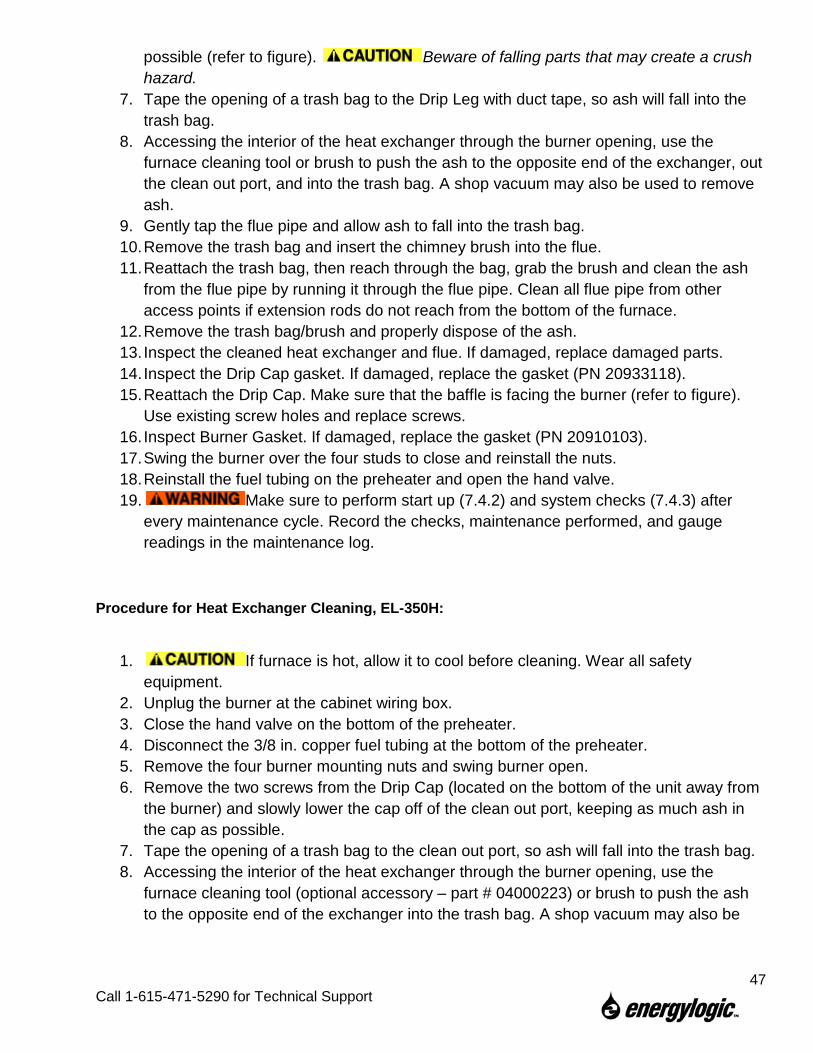
Procedure for Heat Exchanger Cleaning, EL-350H:
1. If furnace is hot, allow it to cool before cleaning. Wear all safety equipment.
2. Unplug the burner at the cabinet wiring box. 3. Close the hand valve on the bottom of the preheater. 4. Disconnect the 3/8 in. copper fuel tubing at the bottom of the preheater. 5. Remove the four burner mounting nuts and swing burner open. 6. Remove the two screws from the Drip Cap (located on the bottom of the unit away from
the burner) and slowly lower the cap off of the clean out port, keeping as much ash in the cap as possible.
7. Tape the opening of a trash bag to the clean out port, so ash will fall into the trash bag. 8. Accessing the interior of the heat exchanger through the burner opening, use the
furnace cleaning tool (optional accessory – part # 04000223) or brush to push the ash to the opposite end of the exchanger into the trash bag. A shop vacuum may also be
47
Call 1-615-471-5290 for Technical Support

used to remove ash. Gently tap the flue pipe and allow ash to fall into the heat exchanger and trash bag.
9. Make sure to clean the ash from the top of the baffle (where the flue pipe connects). 10. The flue pipe should be cleaned at least once a year, and whenever it becomes clogged
with ash and/or soot. 11. The flue pipe can be cleaned with a flue brush from the roof by removing the rain cap,
or from the bottom cleaning port by removing the blower from the cabinet and the baffle from the heat exchanger.
12. To remove the blower from the cabinet, make sure the power is off. Then disconnect the blower power wires in the junction box. Then remove the screws holding the blower to the cabinet and carefully slide it off ( Blower is heavy.).
Personally verify that the main power is turned off and locked out at the circuit breaker. 13. Remove the five nuts holding the baffle in the heat exchanger and pull the handle to
slide it out. 14. Remove the trash bag and insert the chimney brush into the flue. 15. Reattach the trash bag, then reach through the bag, grab the brush and clean the ash
from the flue pipe by running it up through the flue pipe. Clean all flue pipe from other access points if extension rods do not reach from the bottom of the furnace.
16. Remove the trash bag/brush and properly dispose of the ash. 17. Inspect the cleaned heat exchanger and flue. If damaged, replace damaged parts. 18. Inspect the Drip Cap gasket. If damaged, replace the gasket (PN 06000578). 19. Reattach the Drip Cap. Use existing screw holes and replace screws. 20. Clean and reinstall the baffle. Replace the baffle gasket if necessary (PN 06000584). 21. Clean up any ash that spilled inside the cabinet. 22. Clean and reinstall the blower (see next section), and reconnect the blower power
wires. 23. Inspect Burner Gasket. If damaged, replace the gasket (PN 20910103). 24. Swing the burner over the four studs to close and reinstall the nuts. 25. Reinstall the fuel tubing on the preheater and open the hand valve. 26. Make sure to perform start up (7.4.2) and system checks (7.4.3) after
every maintenance cycle. Record the checks, maintenance performed, and gauge readings in the maintenance log.
48
Call 1-615-471-5290 for Technical Support

Blower and Internal Baffle Can Be Removed for Access to Clean the Flue from the Bottom - 350H
49
Call 1-615-471-5290 for Technical Support

8.5.2 Blower Cleaning
How often? Once every 800 to 1,000 hours of operation.
Tools Required: Screw or 5/16” nut driver, pipe brush, shop vacuum, work gloves, dust mask and safety glasses.
Personally verify that the main power is turned off and locked out at the circuit breaker.
Procedure - All Models: 1. Wear all safety equipment. 2. Remove wire guard from the Blower Wheel side (refer to figure). 3. Using a small pipe brush and shop vacuum, gently clean dust from the Blower Wheel
Blades. Be careful not to damage the blades. 4. When finished, reattach the wire guard.
Blower Cleaning
Remove screws and wire guard.
Gently clean the blower wheel.
50
Call 1-615-471-5290 for Technical Support

8.5.3 Fuel Oil Filter Replacement
How often? Every 800 – 1000 hours of operation, or when the vacuum gauge reads 5 inches Hg higher than readings taken with a clean filter.
Tools Required: Safety glasses, rubber gloves.
Replacement Parts: EnergyLogic Spin-On Fuel Filter (PN 20270185) Spec: Hydraulic/140 Micron/Metal Mesh, max. working pressure 200 psi, 25 GPM capacity. Note: Use only genuine EnergyLogic parts to avoid damage and maintain UL status.
Procedure - All Models: 1. Wear all safety equipment. 2. Close the Fire-Stop Valve or ball valve(s) at the filter head. 3. Use a filter wrench to spin the Fuel Filter off the Filter Head Assembly - counter-
clockwise. Dispose of the fuel filter properly. 4. Clean any debris from the strainer housing. 5. You may fill new Fuel Filter with non-synthetic ATF to quicken the priming process. Do
not use new motor oil or synthetic ATF to fill the filter. 6. Spin the Fuel Filter onto the Strainer Housing - clockwise. Hand-tighten the filter.
Record the meter hours and date on the new filter. 7. Open Fire-Stop Valve or Ball Valve. 8. Refer to Section 7.4.1 “Fuel System Priming” for the priming procedure to ensure no air
remains in the fuel system.
Fuel Filter Replacement
Fire stop valve open Fire stop valve closed
Filter Head Assembly
Fuel Filter
Fire Stop Valve
51
Call 1-615-471-5290 for Technical Support

8.5.4 Preheater Cleaning
How often? Once per year.
Tools Required: 3/4 in. wrench, pipe wrench or vice, wire brush, one gallon of 140°F (60°C) + flashpoint parts washer fluid, safety glasses, rubber gloves.
Replacement Parts: Preheater Gaskets (Qty=2) PN 20940122 (2 5/8” O.D.)
Removing Preheater
Procedure - All Models (refer to figures): 1. Wear all safety equipment. 2. Unplug the burner at the cabinet wiring box. 3. Disconnect the Preheater Connector at the Burner Wiring Box, allow it to cool.
Until the preheater has cooled, the parts and the oil are hot. 4. Close the preheater inlet valve and disconnect the fuel tubing from the Inlet and Outlet
Ports of the Preheater. 5. Remove the Preheater mounting bolt and Preheater from the burner.
Unplug burner
Preheater Inlet Valve
Preheater Outlet Tubing
Preheater Connector at burner wiring box.
Mounting bolt
52
Call 1-615-471-5290 for Technical Support

6. Open the Preheater Valve and drain fuel into your tank.
Cleaning Preheater
7. Hold Top Cap (outlet) firmly in a vice or with a pipe wrench and unscrew the housing to expose the finned aluminum Extrusion. Do not attempt to unscrew the Extrusion from the top cap. Do not spray the electrical wiring and components with parts washing fluid. This will damage the electrical circuits in the Preheater and void warranty.
8. Remove old gasket found in the cap above the Extrusion. 9. Use a wire brush and parts washer fluid to clean the Extrusion—clean thoroughly to
remove all loose debris that could block passages. Note: Filling most of the housing with parts washer fluid and placing the Extrusion back into the housing to soak, may quicken the process.
10. Clean the housing and Top Cap with parts washer fluid. 11. Unscrew the Bottom Cap (inlet) from the housing. 12. Remove the old gasket from the cap. 13. Clean the cap and valve, then replace the gasket. 14. Reinstall the Bottom Cap onto the housing. 15. Replace the Top Cap gasket by carefully sliding it over the extrusion. 16. Reinstall the Extrusion/Top Cap onto the housing. Do not over-tighten. 17. Remount the Preheater onto the burner. 18. Reconnect the fuel tubing to the Inlet and Outlet ports of the Preheater. 19. Refer to Section 7.4.1. “Fuel System Priming” for the priming procedure to ensure no air
remains in the fuel system. 20. Make sure no leaks are present at the Top and Bottom Caps of the Preheater. 21. Make sure to perform start up (7.4.2) and system checks (7.4.3) after
every maintenance cycle. Record the checks, maintenance performed, and gauge readings in the maintenance log.
Top Cap
Extrusion
Gasket
Gasket
Bottom Cap
Housing
53
Call 1-615-471-5290 for Technical Support

8.5.5 Nozzle Line Assembly Cleaning
How often? Once per year or if the nozzle becomes blocked with debris (if blocked, a higher operating fuel pressure will be seen on the pump pressure gauge).
Tools Required: 7/16 in., 1/2 in., 3/4 in. and 17mm (boxed end/12-pt.) wrenches, 5/8 in. socket/ratchet, 5/8 in. wrench, 1/4 in. nut driver, hex wrench, vise, flat-blade screwdriver, small wire brush or pipe cleaner (from optional maintenance accessory brush kit), parts washer fluid, shop air gun, safety glasses, rubber gloves.
Replacement Parts: Nozzle O-ring (PN 20213152) or Nozzle (PN 20210123 for EL-140H/EL-200H, PN 20210124 for EL-350H)
Personally verify that the main power is turned off and locked out at the circuit breaker.
Procedure - All Models (Refer to figures): 1. Wear all safety equipment.
2. Remove the preheater and burner from the furnace (refer to previous sections). 3. Using a 7/16” wrench, disconnect the fuel and air tubing from the Nozzle Block. 4. Using a 17mm boxed-end/12-pt.wrench, remove the knurled nuts from the Nozzle Block
(refer to figure). 5. Using a flat-blade screwdriver, loosen the Ignition Transformer screws. Rotate tabs out
of the way and lift the Ignition Transformer back on its hinge.
Disconnecting Nozzle Block
Flare and knurled nuts. Loosen fuel and air tubing connections from nozzle assembly.
Ignition Transformer
Loosen tabs and swing up the transformer cover. Disconnect 2-pin connector (underneath cover).
54
Call 1-615-471-5290 for Technical Support

6. Disconnect nozzle heater Two-Pin Connector.
7. Slide Nozzle Block Assembly out through the air tube.
8. Unscrew the Electrode Screw and remove the Electrode from the Nozzle Assembly. 9. Inspect the electrode wire for excessive wear and the porcelain for cracks - replace as
necessary.
10. Remove the Retention Head by loosening the collar set screw. 11. Slide the Air Vane off the Nozzle Line Assembly. 12. Using a 5/8 in. socket/ratchet, remove the Nozzle from the Nozzle Block Assembly.
Slide nozzle assembly out of burner assembly.
Removing Nozzle Block
Inspect Electrodes for Wear
Disassemble Nozzle Block
Set Screw Retention Head
Nozzle Block Assembly
Air Vane
Electrode Assembly
Nozzle
2-Pin Connector
Nozzle Block Assembly
New Electrodes Worn Electrodes. Narrowed wire diameter and increased gap.
2-Pin
Spacer
55
Call 1-615-471-5290 for Technical Support

13. Using a pair of pliers and a towel, gently clamp the stem of the Nozzle (a small spinner is loosely contained inside the Nozzle) and spin (counter-clockwise) the cap from the stem. *Skip steps13-17 if installing new nozzle.
14. Clean all the parts with parts washing fluid. 15. Replace the stem o-ring. 16. Holding the stem vertically, place the spinner on top of
the stem. Then, thread the nozzle Cap onto the stem. 17. Tighten the nozzle Cap to the stem.
18. The passage through the nozzle block for the nozzle has a plug at the opposite end of the nozzle which must be removed for complete cleaning of the Passage - use thread sealer during reinstallation (refer to figure).
19. IMPORTANT!—Being careful not to apply parts washer fluid to the heater wiring harness, clean the nozzle passage of the Nozzle Block. Make sure parts are clean and dry prior to reassembly.
20. Refer to the following section (8.5.6) for Flame Retention Head and Electrode Settings and reassemble the Nozzle Line Assembly. Be sure to re-install the air vane (shown in figure) in the proper location – opposite side of bulkhead fitting). Failure to install this component properly will result in an off-center flame, which may damage the heat exchanger and void the heat exchanger warranty.
21. Make sure to perform start up (7.4.2) and system checks (7.4.3) after every maintenance cycle. Record the checks, maintenance performed, and gauge readings in the maintenance log.
Disassemble Nozzle Passage Plug
Plug
Nozzle
Cap
Spinner
Stem
O-Ring Air Vane
56
Call 1-615-471-5290 for Technical Support

8.5.6 Retention Head and Electrode Settings
How often? Once per year (refer to 8.5.5, Nozzle Line Cleaning)
Procedure - All Models. NOTE: There are two Electrode/Retention Head designs: one where the electrodes wires make two 90 degree bends (called “Double Bend”), and one with a single angled bend. The “Single Bend” design only goes with Retention Heads with the added center cutout.
Refer to Section 8.5.5 for removal of nozzle block and electrode assembly. Inspect the locations of the electrode components. If adjustments are necessary, use needle-nose pliers to adjust electrode wires. Use the following specifications:
• The Electrode Gap: 3/32” (2.4 mm). • Electrode Tips must be 1/16” (1.6 mm) behind the Cap of the Nozzle. • Nozzle protrudes approximately 1/8” (3 mm) beyond Retention Head vanes. • Vertical location of electrode wires: 7/16” (1.6 mm) from center nozzle to wires. Make
sure that there is a gap between the electrode wires and the nozzle. Make sure there is a gap between the retention head inner diameter and the electrode wires.
NOTE: For the “Single Bend” electrode, the same settings are used, but the electrode wires come down at an angle, as shown below.
3/32” (2.4 mm) Gap
1/16” (1.6 mm) (Electrode behind tip)
1/16” – 1/8” (Flame Retention Head recessed inside Air Tube) (1.5 – 3 mm)
Retention Head
Air Tube
Center Retention Head within Air Tube.
Nozzle must extend approx. 1/16 to 1/8” (1.5 to 3 mm) beyond air vanes.
Air Vanes
Settings for Retention Head & Electrodes – “Double Bend” Electrodes
7/16” (11 mm)
57
Call 1-615-471-5290 for Technical Support

• Retention Head is recessed approximately 1/16” - 1/8” (1.5 – 3 mm) into the Air Tube. • Retention Head is centered within the Air Tube. If not centered, straighten the centering
Tabs of the Retention Head if they are bent. Loosen the knurled nuts, center the Retention Head and retighten the knurled nuts if necessary.
• Make sure air vane is properly installed, on the left side when looking from the nozzle end. It should be locked in place by the retention head base.
• For the “Double Bend” electrodes, the retention head should be installed with one leg vertical, and the electrodes straddle that leg.
• For the “Single Bend” electrodes, the extra cutout in the center hole of the retention head should be centered vertically, and the electrodes are mounted in that cutout between two legs. A tab on the collar of the retention head fits into the channel on the bottom of the electrode ceramic for alignment. (See figures below.)
Air Vane
Single Bend Retention Head & Electrode
Orientation
Double Bend Retention Head & Electrode Orientation
58
Call 1-615-471-5290 for Technical Support

8.5.7 Solenoid Valve Cleaning
How often? Once per year or if the solenoid valve is blocked with debris (higher operating pressure will be seen on the pressure gauge).
Tools Required: 5/16 inch and 7/16 inch wrenches, flat-blade screwdriver, small wire brush or pipe cleaner, pocket pick, parts washer fluid, shop air gun, rubber gloves, safety glasses.
Replacement Parts: Solenoid O-ring (PN 20293199). Nucleus w/ Spring (PN 20293198).
Personally verify that the main power is turned off and locked out at the circuit breaker. Small parts – do not drop / lose.
Procedure - All Models (refer to figures):
1. Wear all safety equipment. 2. Using a 7/16 inch wrench, remove the two fuel tubing fittings from the Solenoid Valve
(refer to figure). 3. Loosen the fittings at the other end of the fuel tubing at the preheater and burner nozzle
block, then rotate the tubing out of the way (refer to figure).
4. Remove the E-Clip from the top of the solenoid. Slide the solenoid body and stem from the bottom of the housing (you may need to rotate the housing).
5. Using a 5/16 in. wrench, unscrew the valve stem from the body by turning the stem
counterclockwise. Secure the body while turning the stem. 6. Inspect the Body for any abnormalities or debris in the inlet/outlet ports and internal
cavity. 7. Inspect the O-ring. Replace if damaged.
Loosen
Loosen
Disconnect Fuel Tubing
Disconnect Fuel Tubing
Solenoid Valve
Disconnect Solenoid Valve
59
Call 1-615-471-5290 for Technical Support

8. Inspect the seal at the end of the nucleus and note if it has an excessive impression from where it seals in the internal cavity of the body. Replace if damaged – nucleus and spring, sold separately.
9. Clean out the inside of the stem with parts washer fluid, then blow dry. 10. Remove excessive carbon build up with a small pick, making sure not to damage any
surfaces. 11. Reassemble the Solenoid Valve in reverse order of disassembly. Make sure the arrow
is pointing in the correct direction of flow. 12. Make sure to perform start up (7.4.2) and system checks (7.4.3) after
every maintenance cycle. Record the checks, maintenance performed, and gauge readings in the maintenance log
Remove E-Clip
Slide Valve out
Body
O-Ring
Nucleus
Spring
Spring Washer
Stem
Rotate
Remove Valve.
Disassemble Valve
60
Call 1-615-471-5290 for Technical Support

8.5.8 Air Compressor Maintenance
How often? Once per year. More often for dusty conditions.
Tools Required: 1/8 inch Allen wrench, 7/16 inch wrench, flat-blade screwdriver, EnergyLogic Air Compressor Pressure Gauge Kit (PN 05000092), Gast compressor cleaning fluid, shop towel, rubber gloves, safety glasses.
Procedure - All Models (refer to figures): 1. Wear all safety equipment. 2. Replace the compressor air filter annually
(PN 20210112). 3. Check the air compressor output by using
the EnergyLogic compressor test kit (PN 14012100). Remove the copper tubing from the outlet of the compressor and from the bulkhead fitting on the burner. Attach one of the tubes in the kit to the 3/16” outlet fitting on the compressor, and the other tubing to the bulkhead fitting. Attach both tubes to the gauge in the kit. Be careful to not make kinks in the tubing.
4. Start the burner by moving the wall thermostat above room temperature and note the air compressor output on the gauge. If the gauge reading is in the 9-11 PSI range, the air compressor is operating as designed and no further maintenance is required. Remove the test kit and reinstall the 3/16” tubing, for normal operation.
5. If the gauge reading is below 9 PSI, check/do the following: A. Coupling
1. Inspect the air compressor coupling by unplugging the burner, loosening the Ignition transformer screws, then lifting it back on its hinge.
Coupling to Compressor
2. Spin the squirrel cage and note if the coupling slips on the burner motor or air compressor shaft.
3. If the coupling is slipping, use a 1/8 inch Allen wrench to tighten the set screw. 4. If the set screws are tight, inspect the metal ends of the coupling for damage. Replace
as necessary. B. Vanes
Air Compressor
Coupling (Parts removed from illustration for clarity.)
Set Screws
Remove Filter
Inlet
3/16” Outlet Fitting
61
Call 1-615-471-5290 for Technical Support

Compressor Vanes
1. Using a 9/64 inch Allen wrench, carefully remove the air compressor cover plate and carbon gasket.
2. Inspect the carbon gasket for wear—reverse if worn or replace as necessary. 3. Spin the squirrel cage using a screwdriver. 4. If the vanes do not move in their slots as the rotor turns, clean the vanes. Clean the
vanes and compressor body using Gast compressor cleaning fluid or suitable equivalent. Note: Do not use petroleum solvents, such as engine degreasers. These fluids leave unwanted residues behind that may cause the vanes to stick and/or bind. If the vanes are worn out, you may purchase a vane replacement kit (PN 10013106).
5. Reassemble the air compressor. Be careful not to over-tighten the cover plate.
C. Cleaning Wear Safety Glasses.
1. Disconnect the fitting at the air compressor outlet. 2. Disconnect the preheater outlet tubing from the solenoid valve and run into a bucket to
catch the oil. 3. Jump the primary control T-terminals, then F-terminals to operate the burner. 4. Feed several drops of the Gast compressor cleaning fluid into the air compressor inlet
and catch the spray at the outlet using a shop towel. 5. Allow the burner to run 3-4 minutes to flush out all the fluid from the air compressor,
then remove the jumpers. 6. Replace the air compressor filter, reconnect the outlet tubing. 7. Reconnect the preheater outlet tubing.
Cover Plate
Carbon Gasket
(4) Vanes
62
Call 1-615-471-5290 for Technical Support
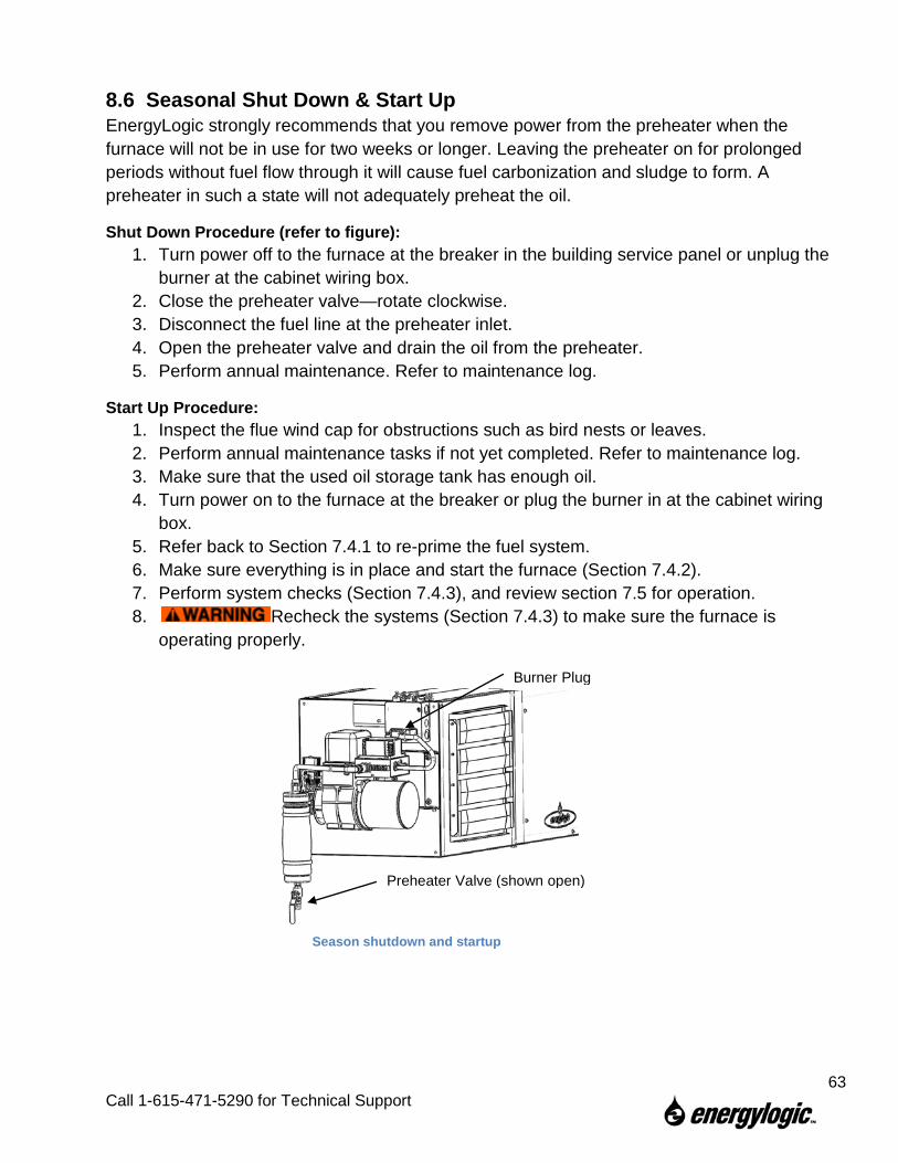
8.6 Seasonal Shut Down & Start Up EnergyLogic strongly recommends that you remove power from the preheater when the furnace will not be in use for two weeks or longer. Leaving the preheater on for prolonged periods without fuel flow through it will cause fuel carbonization and sludge to form. A preheater in such a state will not adequately preheat the oil.
Shut Down Procedure (refer to figure): 1. Turn power off to the furnace at the breaker in the building service panel or unplug the
burner at the cabinet wiring box. 2. Close the preheater valve—rotate clockwise. 3. Disconnect the fuel line at the preheater inlet. 4. Open the preheater valve and drain the oil from the preheater. 5. Perform annual maintenance. Refer to maintenance log.
Start Up Procedure: 1. Inspect the flue wind cap for obstructions such as bird nests or leaves. 2. Perform annual maintenance tasks if not yet completed. Refer to maintenance log. 3. Make sure that the used oil storage tank has enough oil. 4. Turn power on to the furnace at the breaker or plug the burner in at the cabinet wiring
box. 5. Refer back to Section 7.4.1 to re-prime the fuel system. 6. Make sure everything is in place and start the furnace (Section 7.4.2). 7. Perform system checks (Section 7.4.3), and review section 7.5 for operation. 8. Recheck the systems (Section 7.4.3) to make sure the furnace is
operating properly.
Burner Plug
Preheater Valve (shown open)
Season shutdown and startup
63
Call 1-615-471-5290 for Technical Support