80% a rms ar-15 jig manual · ar-‐15 jig manual ver. 1.1 page 1 80% a rms ar-15 jig manual thank...
TRANSCRIPT

Copyright 2013 80% Arms LLC AR-‐15 Jig Manual Ver. 1.1 Page 1
8800%% AArrmmss AARR--1155 JJiigg mmaannuuaall
Thank you for purchasing our AR-‐15 jig. This precision self-‐aligning jig will allow you to finish your 80% Arms and other 80% lowers using only a drill press and a few common tools. Please read all of the directions from start to finish before starting any work on your lower. Keep in mind that once you start drilling, milling, or altering your 80% lower it becomes a firearm and all local, state, and federal firearms laws apply. It is your responsibility to check the legality of finishing an 80% lower in your area. Specifications: Hole Sizes: Selector Pin Hole: 3/8” (0.375”) Trigger Pin Hole: 5/32” (0.156”) Hammer Pin Holes: 5/32” (0.156”) Adapter Plates Thickness: 0.60” Recommended Bits: 1/8” Drill Bit (0.125”) 17/64” Drill Bit (0.266”) 3/8” Drill Bit (0.375”) 7/16” Drill Bit (0.438”) 1/2” Drill Bit (0.500”) 1/4" Carbide Endmill (0.250”) * Minimum 2.5” long 3/8” Carbide Endmill (0.375”) * Minimum 2.5” long Carbide Endmills (Actual Size) Depths: Trigger / Fire Control Pocket 1.250” Deep Shelf Pocket 0.630” Deep Other Materials Needed: Drill press with adjustable crank table or feed lever for milling Safety goggles for eye protection Cutting fluid such as SafeTap Ultima when milling (A lubricant such as WD-‐40 can be used if you do not have machining cutting fluid available.)

Copyright 2013 80% Arms LLC AR-‐15 Jig Manual Ver. 1.1 Page 2
Parts Description: Your jig kit consists of a right and left jig wall, a drilling adapter plate, trigger / fire control milling adapter plate, shelf and trigger slot milling adapter plate, four 1” x 1/4” Allen bolts, and four 2” x 1/4” Allen bolts.
Copyright 2013 80% Arms LLC AR-‐15 Jig Manual Ver. 1.1 Page 3
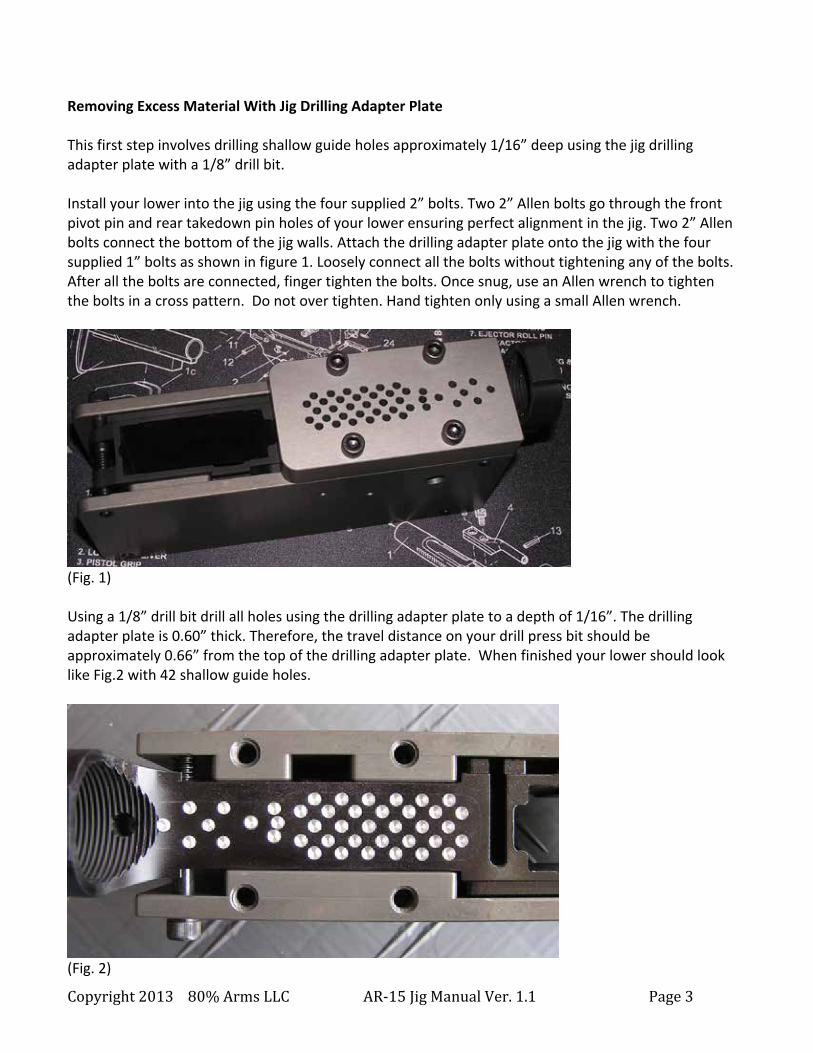
Removing Excess Material With Jig Drilling Adapter Plate This first step involves drilling shallow guide holes approximately 1/16” deep using the jig drilling adapter plate with a 1/8” drill bit. Install your lower into the jig using the four supplied 2” bolts. Two 2” Allen bolts go through the front pivot pin and rear takedown pin holes of your lower ensuring perfect alignment in the jig. Two 2” Allen bolts connect the bottom of the jig walls. Attach the drilling adapter plate onto the jig with the four supplied 1” bolts as shown in figure 1. Loosely connect all the bolts without tightening any of the bolts. After all the bolts are connected, finger tighten the bolts. Once snug, use an Allen wrench to tighten the bolts in a cross pattern. Do not over tighten. Hand tighten only using a small Allen wrench.
(Fig. 1) Using a 1/8” drill bit drill all holes using the drilling adapter plate to a depth of 1/16”. The drilling adapter plate is 0.60” thick. Therefore, the travel distance on your drill press bit should be approximately 0.66” from the top of the drilling adapter plate. When finished your lower should look like Fig.2 with 42 shallow guide holes.
(Fig. 2)

Copyright 2013 80% Arms LLC AR-‐15 Jig Manual Ver. 1.1 Page 4
Remove the drilling adapter plate from the jig to make it easier to drill the holes to their proper depth. Refer to color-‐coded Fig. 3 for hole depth reference. Note that some drill bit coatings, such as titanium, may clog the drill bit quickly when drilling the small holes in aluminum. If you are having problems with the drill bit clogging excessively, use one with a different coating or a non-‐coated steel bit. Using a 1/8” drill bit drill the 36 green holes to a depth of 1.249” from the top of the lower receiver. Using a 1/8” drill bit drill the 3 yellow holes to a depth of 0.629” from the top of the receiver. Do not drill out the 3 red holes. Your lower should now look like Fig. 4.
(Fig. 3)
(Fig. 4)

Copyright 2013 80% Arms LLC AR-‐15 Jig Manual Ver. 1.1 Page 5
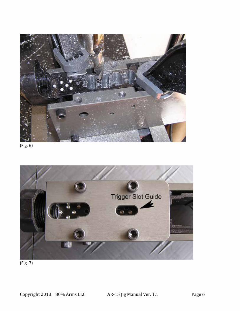
Prior to drilling the 3 red holes, you will need to loosen and partially slide out the jig bolt which is securing the lower receiver through the rear takedown pin holes. Do not fully remove the bolt but slide it out just enough to allow the 1/8” drill to clear the bolt when drilling the holes. If the bolt is completely removed the lower may shift out of alignment in the jig. Drill the 3 red holes to a depth of 0.629” and then retighten the bolt. To prevent the jig from moving or the drill bits from walking, securing the jig to the drill press table when drilling the next set of larger holes is recommended. (Quick release C-‐Clamps can be used to quickly reposition and secure the jig to the drill press table between holes.) Be sure to drill very slowly using light pressure to stay centered on the 1/8” pilot holes and prevent the drill bit from walking into an adjacent hole. Use color-‐coded Fig. 5 below for reference when drilling the next set of holes. Use a 3/8” drill bit to drill the blue holes to a depth of 1.249” from the top of the lower. You may want to skip a column when drilling to keep the pressure equal on both sides of the drill bit. After drilling alternating columns, return and drill the skipped holes. (See Fig. 6 example below.)
(Fig. 5) Use a 7/16” drill bit to drill the brown hole to a depth of 1.249” from the top of the receiver. Using a 17/64” drill bit, slowly drill through the white holes to a depth of 1.4” from the top of the lower. These holes will go all the way through the bottom of the receiver and will be used later for milling the trigger slot. To make sure you are drilling through the correct holes, you can install the rear shelf / trigger slot plate prior to drilling. If drilling with the plate installed, add 0.60” to the depth to allow for the thickness of the plate and drill to a depth of 2.0”. (See Fig. 7) Do not drill the 1/2” purple holes yet.
Copyright 2013 80% Arms LLC AR-‐15 Jig Manual Ver. 1.1 Page 6
(Fig. 6)
(Fig. 7)

Copyright 2013 80% Arms LLC AR-‐15 Jig Manual Ver. 1.1 Page 7
Drilling Selector, Hammer, and Trigger Pin Holes Prior to drilling these holes make sure the jig is flat on the drill press table. If any of the jig bolts are protruding from the side of the jig wall, grind down the bolts to make them flush with the jig wall or use a couple of the guide plates between the bolts and bolt heads to create a level drilling surface. Drilling selector pin hole: Lay the jig on its right side. Using a 3/8” drill bit align the selector pin hole on the jig wall with the drill bit and drill to a depth of 0.85” from the face of the jig wall. Flip the jig over on its left side and repeat the procedure. See Fig. 8.
(Fig. 8) Drilling trigger and hammer pin holes: Lay the jig on its right side. Using a 5/32” drill bit align the trigger pin hole with the drill bit and drill to a depth of 0.70” from the face of the jig wall. Using the same 5/32” drill bit align the hammer pin hole with the drill bit and drill to a depth of 0.70” from the face of the jig wall. Flip the jig over onto its left side and repeat the procedure. See Fig. 9.

Copyright 2013 80% Arms LLC AR-‐15 Jig Manual Ver. 1.1 Page 8
(Fig. 9) Drilling Rear Shelf 1/2” Holes Insert a 3/8” rod through the jig’s selector hole into the lower and remove the bolt securing the lower to the jig in the rear takedown pin hole. If you don’t have a 3/8” rod, insert the shank (smooth portion) of a 3/8” drill through the jig wall and into the lower to secure the lower in the jig. This is only to prevent the lower from getting pushed down in the jig while drilling the 1/2” holes in the shelf area. The drill or rod only needs to go in about 0.75” from the jig wall to support the lower. It is not necessary to push the rod all the way through the lower. Use a 1/2” drill bit to drill the 2 purple holes in Fig. 6 to a depth of 0.629” from the top of the receiver. Again, drill slowly with light pressure so the drill bit stays centered on the 1/8” pilot holes. You should secure the jig to the drill table to keep it from moving while drilling the holes. When finished with these holes your lower should look something like Fig. 10 with a lot of material removed. Screw the 2” bolt though the jig and takedown pins and tighten. Remove the rod or drill from the selector hole. You are now ready to start milling.

Copyright 2013 80% Arms LLC AR-‐15 Jig Manual Ver. 1.1 Page 9
(Fig. 10) Milling the Lower Receiver Trigger Pocket Attach the 3/8” carbide endmill to the drill press. Make sure the endmill it secured very tightly on the chuck or vibration during milling may loosen the endmill causing damage. Adjust the depth of the endmill so at least 1/4” (0.25”) of the endmill’s shank is touching the adapter plate. (See Fig. 11) If you don’t do this you may cut into your adapter plate. If the adapter plate is getting cut, your drill press or drill press table isn’t level or you are not holding the jig firmly level on the drill press table.
(Fig. 11)
Copyright 2013 80% Arms LLC AR-‐15 Jig Manual Ver. 1.1 Page 10
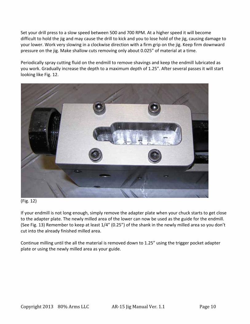
Set your drill press to a slow speed between 500 and 700 RPM. At a higher speed it will become difficult to hold the jig and may cause the drill to kick and you to lose hold of the jig, causing damage to your lower. Work very slowing in a clockwise direction with a firm grip on the jig. Keep firm downward pressure on the jig. Make shallow cuts removing only about 0.025” of material at a time. Periodically spray cutting fluid on the endmill to remove shavings and keep the endmill lubricated as you work. Gradually increase the depth to a maximum depth of 1.25”. After several passes it will start looking like Fig. 12.
(Fig. 12) If your endmill is not long enough, simply remove the adapter plate when your chuck starts to get close to the adapter plate. The newly milled area of the lower can now be used as the guide for the endmill. (See Fig. 13) Remember to keep at least 1/4” (0.25”) of the shank in the newly milled area so you don’t cut into the already finished milled area. Continue milling until the all the material is removed down to 1.25” using the trigger pocket adapter plate or using the newly milled area as your guide.

Copyright 2013 80% Arms LLC AR-‐15 Jig Manual Ver. 1.1 Page 11
(Fig. 13) Milling Shelf Area Attach the rear shelf / trigger slot adapter plate to the jig to mill the rear shelf area as shown below in Fig. 14. The maximum depth for milling the rear shelf is 0.630” from the top of the lower receiver. Use caution when milling the rear shelf area not to mill into the jig bolt. Remember to start with at least 1/4” (0.25”) of the shank touching the adapter plate to prevent damage to the adapter plate. Slowly and carefully mill the area in front of the jig bolt.
(Fig. 14)

Copyright 2013 80% Arms LLC AR-‐15 Jig Manual Ver. 1.1 Page 12
After the area in front on the jig bolt is milled, unscrew and slide out the jig bolt and use the same process used to stabilize the jig that was used when drilling the red 1/8” holes by inserting a 3/8” rod or drill shank through the jig into the lower’s selector hole. Now mill the rear area of the shelf. Use caution not to mill into the drill shank or rod that is securing the lower in the jig. When finished milling the shelf, screw the jig bolt back in and remove the 3/8” drill shank or rod from the selector hole. Milling the Trigger Slot Install the 1/4” (0.25”) carbide endmill into the drill press. Carefully lower the endmill through the trigger slot adapter plate until the end mill passes through the 17/64” holes(s) previously drilled through the lower. (See Fig. 15) The distance from the top of the trigger slot adapter plate to the bottom of the lower is 2.0”. If using a long endmill be careful not to go much past 2” or you may strike the lower’s trigger guard. Working in a slow clockwise direction, mill out the trigger slot. Pay careful attention that the endmill shank rides along the adapter plate wall and that the drill chuck is not bumping against the heads of the bolts that are securing the adapter plate. If the drill chuck is too close to the adapter plate it may bump the head of the bolts preventing the endmill from fully milling the trigger slot hole.
(Fig. 15)
Copyright 2013 80% Arms LLC AR-‐15 Jig Manual Ver. 1.1 Page 13
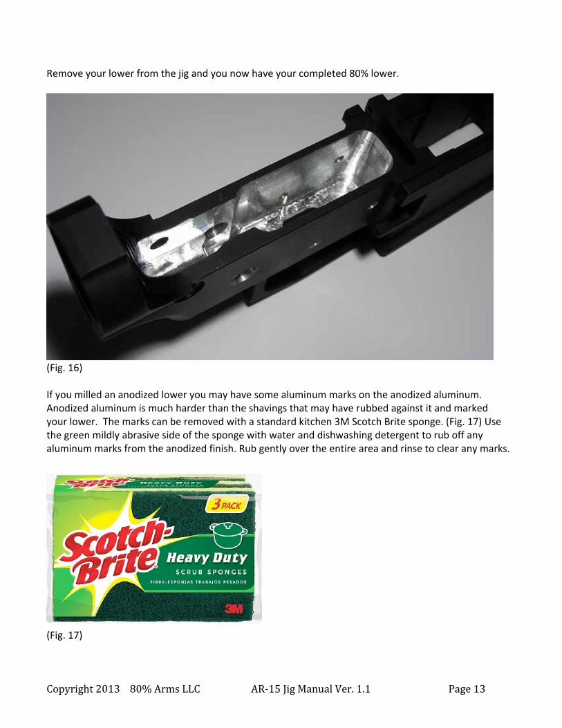
Remove your lower from the jig and you now have your completed 80% lower.
(Fig. 16) If you milled an anodized lower you may have some aluminum marks on the anodized aluminum. Anodized aluminum is much harder than the shavings that may have rubbed against it and marked your lower. The marks can be removed with a standard kitchen 3M Scotch Brite sponge. (Fig. 17) Use the green mildly abrasive side of the sponge with water and dishwashing detergent to rub off any aluminum marks from the anodized finish. Rub gently over the entire area and rinse to clear any marks.
(Fig. 17)
Copyright 2013 80% Arms LLC AR-‐15 Jig Manual Ver. 1.1 Page 14
Working with power tools is dangerous. Please follow all safety instructions from your tools’ manufacturers. Always wear eye protection when drilling, milling, or using any tools. Your completed, partially completed, or altered 80% lower is considered a firearm by law. You must comply will all local, state, and federal firearms laws once you begin drilling or milling your 80% lower. Failure to follow applicable laws can result in your arrest and a criminal record. Check with your local, state, and federal authorities before using this jig with any 80% lower. This guide is copyrighted by 80% Arms LLC. The images and content of this guide cannot be copied or distributed without prior written permission from 80% Arms LLC. This full guide may be linked online for non-‐commercial purposes only as long as the link is a direct link from 80percentarms.com. For sales and support please contact: 80% Arms LLC P.O. Box 27059 Santa Ana, CA 92799 (949) 354-‐ARMS [2767] [email protected] www.80percentarms.com