800 north glebe - penn state college of engineering · a hollow core plank system was designed...
TRANSCRIPT

800 NORTH GLEBE Arlington, VA
Ryan Johnson Structural Option
Advisor: Dr. Linda Hanagan
October 29, 2009
Technical Report 2

Ryan Johnson 800 North Glebe Structural Option Arlington, VA Dr. Linda Hanagan Technical Report #2
Page 2 of 54
Table of Contents
Executive Summary…………………………………………………………..………..3
Introduction…………………………………………………………………….…….…..4
Architectural Design Overview…………………………………………….……..5
Structural Systems Overview………………………………………….…….…….7 Foundation…………………………………………………………………………..…………..7 Superstructure………………………………………………………………..…………….….7 Lateral System……………………………………………………………………....………...9
Design Codes and Standards……………………………………………….……..10
Material Properties…………………………………………………………….……..12
Building Loads…………………………………………………………………….……..13 Live Loads…………………………………………………………………………..…………...13
Dead Loads………………………………………………………………………….……….....14
Floor System Analysis……….……………..…………….…………………….……15 Existing One-way slab on PT Girder.……………………….………………………..15
Two-Way Post Tensioned (New Grid)…………………………………………..…. 17 Two-Way Post Tensioned (Existing Grid)….…………………………………..….20 Hollow Core Precast on Steel beam (New Grid)…………….………………….23
Floor System Comparison...……………..…………….…………………….……25
Floor System Conclusion.....……………..…………….……………………….…28
Appendices…………………………………………………………………….……...….29 Appendix A: Existing One-way slab on PT Girder..………….….……………..29 Appendix B: Two-Way Post Tensioned (New Grid)………………….………..35 Appendix C: Two-Way Post Tensioned (Existing Grid)………….….………..48
Appendix D: Hollow Core Precast on Steel..……………………………….……..52 References.…………………………………………………………………….……...….54

Ryan Johnson 800 North Glebe Structural Option Arlington, VA Dr. Linda Hanagan Technical Report #2
Page 3 of 54
Executive Summary This Pro-Con Structural Study of Alternative Floor System Report studies and compares the existing floor framing and three alternative floor framing systems for 800 North Glebe. 800 North Glebe is a ten story mixed-used office building that will redefine the Ballston, Virginia skyline. Zoning height restrictions in the Arlington have a maximum height of 153’ and twelve stories for office buildings. With this in mind, I did not find it advantageous to minimize the existing system depth to add an additional level, nor could I increase the slab depth, and therefore, raise the building height while keeping the same floor-to-ceiling dimensions. The floor-to-ceiling height cannot go below 9’-0” for the building to remain class-A office space. The existing structure consists primarily of a 9” one-way mildly reinforced concrete slab over post-tensioned girders arranged in 30’ x 46’ bays. Through the use of ACI 318-08, Approximate Method of Frame Analysis, it was determined the minimum slab thickness would need to be 9” in the short direction and that 72” x 18” post-tensioned girders would support the loading spanning the long direction. Three alternative structural slab systems include:
• Two-way post-tensioned slab (new column layout) • Two-way post-tensioned slab (existing column layout) • Hollow Core precast concrete planks on steam beams (new column layout)
A new column grid was created by analyzing the architectural plans, and a 22’x28’ bay could be accommodated in the superstructure with a minimal change to the plan layout. The two-way post-tensioned slabs were designed using Portland Cement Association (PCA) examples and Holbert Apple references. The two-way post-tensioned slab, with a new column grid layout, was designed to be 9” thick with 16 tendons in a parabolic profile banded at the columns in the short (22’) direction and 20 tendons uniformly distributed over the long (28’) direction. A 14” slab was needed for the two-way post tensioned slab with the existing column layout. However the actual force in the North-South slab was 576 psi, which would be greater than the 300 psi allowable compressive stress. A hollow core plank system was designed using the PCI Design Handbook. By minimizing the column grid, it was determined the girders supporting the slab needed to be W24x74, with a total system depth of 30”. All of the framing systems were then compared to one another regarding weight, depth, cost, feasibility, etc. It was determined that the two-way post tensioned slab with the new column layout would be the most feasible design alternative to further investigate. The slab depth is slim and the alteration to the architectural floor plans would be minimal. Concerns regarding the constructability of the system and any modifications that would be needed to the substructure will be further investigated.

Ryan Johnson 800 North Glebe Structural Option Arlington, VA Dr. Linda Hanagan Technical Report #2
Page 4 of 54
Introduction Located in downtown Arlington, VA, 800 North Glebe offers class-A mixed-use office space and one level of public space. Three levels of below grade parking are shared between 800 N. Glebe and 900 N. Glebe, Virginia Tech’s new research building. Vertical transportation of stairways and elevators bring you from the garage to the large open retail and gathering space. Levels two through ten provide open plan office space. Column spacing of 30’ x 46’ allows for 30,000 square foot floor plates with 9’-0” floor-to-ceiling heights. Building setbacks are located at levels four, six, and eight to aesthetically vary the building and offer different office layouts as seen in figures 1 through 4. The purpose of Technical report II, Structural Study of Alternative Floor Systems, is to gain a better understanding of the current slab system and explore alternatives that meet the design criteria of 800 North Glebe. Upon completion of the four different slab designs, conclusions will be found on the feasibility of a system, or systems, to be further investigated.
Figure 1: Floor Level 3 Figure 2: Floor level 5
Figure 4: Floor Level 8 Figure 3: Floor Level 10

Ryan Johnson 800 North Glebe Structural Option Arlington, VA Dr. Linda Hanagan Technical Report #2
Page 5 of 54
Architectural Overview 800 North Glebe is a 10-story 316,000 square-foot mixed-use office building. Retail and public gathering spaces are located at street level in the 2-story lobby of the building. The remaining nine levels will provide class-A mixed-use offices. 800 North Glebe was designed for LEED Gold Certification by utilizing numerous strategies to minimize its carbon footprint.
Innovative sustainable and responsible design practices are one of the designer’s primary goals. Integration of sustainability and every day design by minimizing the carbon footprint, balancing energy, resources and feasibility all went into design on 800 North Glebe. In accordance with the U.S. Green Building Council’s Leadership in Energy and Environmental Design, the owner has a goal to achieve
LEED Gold Certification, which the designers fulfilled. LEED Gold
Certification requires the design to attain at least 34 out of 61 possible points.
The 10-story façade, created by three sail-like sweeping glass curtain walls, accentuate the sight lines of the building. Radial lines and circles were widely used to define the crown and drum feature of level one and the sail feature of the remaining levels. Refer to figure 5,6 and 7 for visual representation of façade features.
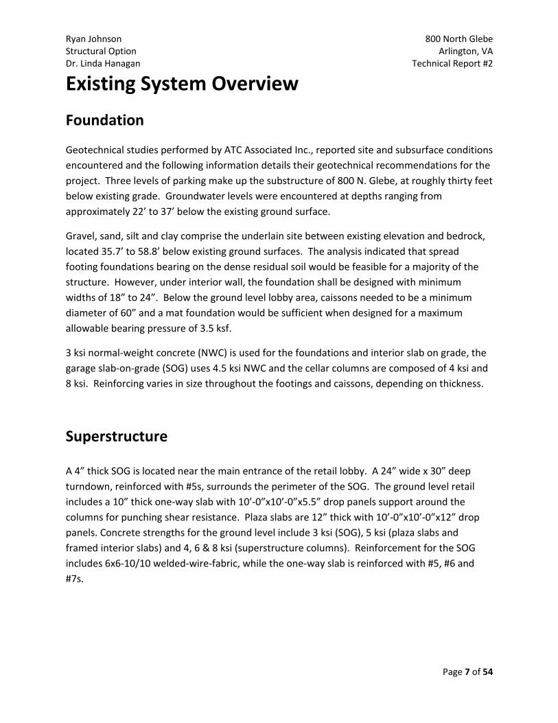
Retail and community spaces on the ground level offer 14’-6” ceiling heights with floor-to-ceiling glazing. Over the main building entrance, there is a diamond expression decorative composite metal canopy with a plaster soffit and sunguard ultrawhite laminated backlit glass as shown in figures 6 and 7.
Figure 5: South East Face
Figure 6: Sail Feature
Ryan Johnson 800 North Glebe Structural Option Arlington, VA Dr. Linda Hanagan Technical Report #2
Page 6 of 54
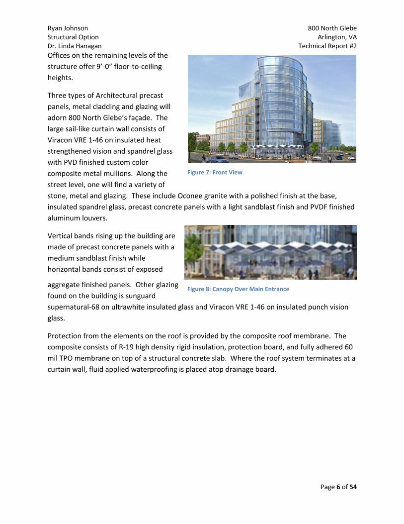
Offices on the remaining levels of the structure offer 9’-0” floor-to-ceiling heights.
Three types of Architectural precast panels, metal cladding and glazing will adorn 800 North Glebe’s façade. The large sail-like curtain wall consists of Viracon VRE 1-46 on insulated heat strengthened vision and spandrel glass with PVD finished custom color composite metal mullions. Along the street level, one will find a variety of stone, metal and glazing. These include Oconee granite with a polished finish at the base, insulated spandrel glass, precast concrete panels with a light sandblast finish and PVDF finished aluminum louvers.
Vertical bands rising up the building are made of precast concrete panels with a medium sandblast finish while horizontal bands consist of exposed
aggregate finished panels. Other glazing found on the building is sunguard supernatural-68 on ultrawhite insulated glass and Viracon VRE 1-46 on insulated punch vision glass.
Protection from the elements on the roof is provided by the composite roof membrane. The composite consists of R-19 high density rigid insulation, protection board, and fully adhered 60 mil TPO membrane on top of a structural concrete slab. Where the roof system terminates at a curtain wall, fluid applied waterproofing is placed atop drainage board.
Figure 7: Front View
Figure 8: Canopy Over Main Entrance
Ryan Johnson 800 North Glebe Structural Option Arlington, VA Dr. Linda Hanagan Technical Report #2
Page 7 of 54
Existing System Overview
Foundation Geotechnical studies performed by ATC Associated Inc., reported site and subsurface conditions encountered and the following information details their geotechnical recommendations for the project. Three levels of parking make up the substructure of 800 N. Glebe, at roughly thirty feet below existing grade. Groundwater levels were encountered at depths ranging from approximately 22’ to 37’ below the existing ground surface.
Gravel, sand, silt and clay comprise the underlain site between existing elevation and bedrock, located 35.7’ to 58.8’ below existing ground surfaces. The analysis indicated that spread footing foundations bearing on the dense residual soil would be feasible for a majority of the structure. However, under interior wall, the foundation shall be designed with minimum widths of 18” to 24”. Below the ground level lobby area, caissons needed to be a minimum diameter of 60” and a mat foundation would be sufficient when designed for a maximum allowable bearing pressure of 3.5 ksf.
3 ksi normal-weight concrete (NWC) is used for the foundations and interior slab on grade, the garage slab-on-grade (SOG) uses 4.5 ksi NWC and the cellar columns are composed of 4 ksi and 8 ksi. Reinforcing varies in size throughout the footings and caissons, depending on thickness.
Superstructure A 4” thick SOG is located near the main entrance of the retail lobby. A 24” wide x 30” deep turndown, reinforced with #5s, surrounds the perimeter of the SOG. The ground level retail includes a 10” thick one-way slab with 10’-0”x10’-0”x5.5” drop panels support around the columns for punching shear resistance. Plaza slabs are 12” thick with 10’-0”x10’-0”x12” drop panels. Concrete strengths for the ground level include 3 ksi (SOG), 5 ksi (plaza slabs and framed interior slabs) and 4, 6 & 8 ksi (superstructure columns). Reinforcement for the SOG includes 6x6-10/10 welded-wire-fabric, while the one-way slab is reinforced with #5, #6 and #7s.
Ryan Johnson 800 North Glebe Structural Option Arlington, VA Dr. Linda Hanagan Technical Report #2
Page 8 of 54
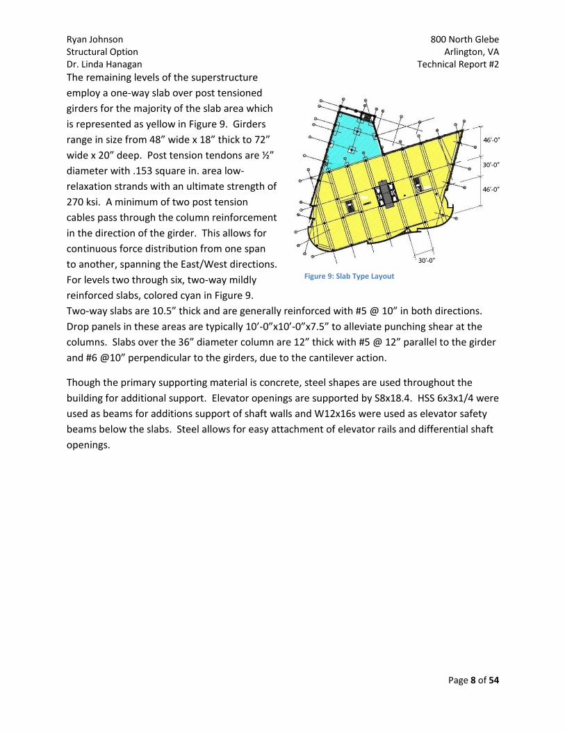
The remaining levels of the superstructure employ a one-way slab over post tensioned girders for the majority of the slab area which is represented as yellow in Figure 9. Girders range in size from 48” wide x 18” thick to 72” wide x 20” deep. Post tension tendons are ½” diameter with .153 square in. area low-relaxation strands with an ultimate strength of 270 ksi. A minimum of two post tension cables pass through the column reinforcement in the direction of the girder. This allows for continuous force distribution from one span to another, spanning the East/West directions. For levels two through six, two-way mildly reinforced slabs, colored cyan in Figure 9. Two-way slabs are 10.5” thick and are generally reinforced with #5 @ 10” in both directions. Drop panels in these areas are typically 10’-0”x10’-0”x7.5” to alleviate punching shear at the columns. Slabs over the 36” diameter column are 12” thick with #5 @ 12” parallel to the girder and #6 @10” perpendicular to the girders, due to the cantilever action.
Though the primary supporting material is concrete, steel shapes are used throughout the building for additional support. Elevator openings are supported by S8x18.4. HSS 6x3x1/4 were used as beams for additions support of shaft walls and W12x16s were used as elevator safety beams below the slabs. Steel allows for easy attachment of elevator rails and differential shaft openings.
Figure 9: Slab Type Layout

Ryan Johnson 800 North Glebe Structural Option Arlington, VA Dr. Linda Hanagan Technical Report #2
Page 9 of 54
Figure 10: Shear Wall Location
Lateral System
Shear walls in the core of the building provide the entire lateral support, as designed (Figure 10). Two 12”thick “C” shaped walls, 31.83’ long East/West and 9.58’ long North/South per each “C”, encase the elevator banks and are reinforced with #4 horizontally and #5 vertically. From the sixth floor down, walls running North/South are specially reinforced three feet from each end with #7 and #8 rebar. All of the shear walls use concrete with a compressive strength of f’c= 8 ksi. Building drift criteria for wind loads is L/400 or 3/8” inter-story drift at typical floors (12’-9” floor-to-floor) and for seismic loads is L/76 or 2” inter-story drift at typical floors (12’-9” floor-to-floor).
Great care was given to limit the size and number of shear walls so as to not modify the floor layouts. However, since the building primarily consists of reinforced concrete, part of the lateral forces could be distributed through these members. RAM Frame was used by Structura to calculate the lateral forces acting on the building. The use of the program took all load combinations into account and analyzed the applied diaphragm and story forces. Future calculations will show how the overall structural system reacts to the lateral forces caused by wind and seismic.
Ryan Johnson 800 North Glebe Structural Option Arlington, VA Dr. Linda Hanagan Technical Report #2
Page 10 of 54
Design Codes and Standards Thesis design had been performed with the most up to date codes and standard available. These may differ from the original design, resulting in possible calculation variations.
Original Design:
• International Building Code, 2003
• Virginia Uniform Building Code, 2003
• American Society of Civil Engineers (ASCE) o ASCE 7-02, Minimum Design Loads for Buildings and Other Structures
• American Concrete Institute (ACI) o Building Code Commentary 318-02 o Structural Concrete for Buildings, ACI 301
• America Institute of Steel Construction (AISC)
o Manual of Steel Construction, Thirteenth Edition, 2005 Thesis Design with Additional References:
• International Building Code, 2006
• Virginia Uniform Building Code, 2003
• American Society of Civil Engineers (ASCE) o ASCE 7-05, Minimum Design Loads for Buildings and Other Structures
• American Concrete Institute (ACI) o Building Code Commentary 318-08
• America Institute of Steel Construction (AISC)
o Manual of Steel Construction, Thirteenth Edition, 2005
• Precast / Prestressed Concrete Institute o PCI Manual for the Design of Hollow Core Slabs, Second Edition, 1998

Ryan Johnson 800 North Glebe Structural Option Arlington, VA Dr. Linda Hanagan Technical Report #2
Page 11 of 54
Deflection Criteria
Horizontal Framing Deflections:
• Live Load o < L/600 or ½”
• Total Load Excluding Self Weight o < L/480 or ¾”
*Horizontal framing deflections are strictly set because of all the brittle finishes being supported by the slabs. The curtain wall system has a lot of dependency on how much the slabs move.
Lateral Drift:
• Wind Loads o < L/400 or 3/8”
• Seismic Loads o < L/76 or 2”
Main Structural Elements Supporting Components and Cladding:
• At Screenwalls o < L/240 or ¾”
• At Floors Supporting Curtainwalls o < L/600 or ½”
• At Roof Parapet Supporting Curtainwalls o < L/600 or ½”
• At Non-Brittle Finishes o < L/240
Ryan Johnson 800 North Glebe Structural Option Arlington, VA Dr. Linda Hanagan Technical Report #2
Page 12 of 54
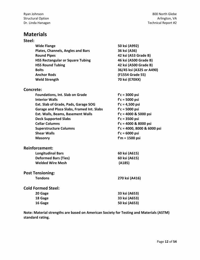
Materials Steel: Wide Flange 50 ksi (A992) Plates, Channels, Angles and Bars 36 ksi (A36) Round Pipes 42 ksi (A53 Grade B) HSS Rectangular or Square Tubing 46 ksi (A500 Grade B) HSS Round Tubing 42 ksi (A500 Grade B) Bolts 36/45 ksi (A325 or A490) Anchor Rods (F1554 Grade 55) Weld Strength 70 ksi (E70XX) Concrete: Foundations, Int. Slab on Grade f’c = 3000 psi Interior Walls f’c = 5000 psi Ext. Slab of Grade, Pads, Garage SOG f’c = 4,500 psi Garage and Plaza Slabs, Framed Int. Slabs f’c = 5000 psi Ext. Walls, Beams, Basement Walls f’c = 4000 & 5000 psi Deck Supported Slabs f’c = 3500 psi Cellar Columns f’c = 4000 & 8000 psi Superstructure Columns f’c = 4000, 8000 & 6000 psi Shear Walls f’c = 6000 psi Masonry f’m = 1500 psi Reinforcement:
Longitudinal Bars 60 ksi (A615) Deformed Bars (Ties) 60 ksi (A615)
Welded Wire Mesh (A185) Post Tensioning: Tendons 270 ksi (A416) Cold Formed Steel: 20 Gage 33 ksi (A653) 18 Gage 33 ksi (A653) 16 Gage 50 ksi (A653) Note: Material strengths are based on American Society for Testing and Materials (ASTM) standard rating.

Ryan Johnson 800 North Glebe Structural Option Arlington, VA Dr. Linda Hanagan Technical Report #2
Page 13 of 54
Building Loads
Live Loads ASCE 7-05, Minimum Design Loads for Buildings and other Structures, was the main reference for determination of loads in this project for 800 North Glebe. These loads were compared to the loads specified by the designer per IBC 2003 and the 2003 Virginia Uniform State Building Code which references ASCE 7-02. A few loadings used by the designer were seen to be greater, i.e. garage entry, and therefore the larger value was used because of the significant increase. These values are outlined in table 1 below.
Live Loads Description Location Designer Loads (ASCE 7-05) Thesis Loads
Parking P3 40 40 40 Stairs P3 100 100 100
Parking P2 40 40 40 Stairs P2 100 100 100
Parking P1 40 40 40 Stairs P1 100 100 100
Garage Entry Level 1 250 50 250
Main Retail/Assembly Level 1 100 125 250
100 100
Elevator Lobby Level 1 100 100 100 Entry Level 1 100 100 100
Loading Dock Level 1 350 350 Yards and Terraces Level 1 100 100 100
Marquees and Canopies Level 2 75 75 75
Corridors Above First Floor
Level 2-10 100 80 80
Walkways and Elevated Platforms
60 60 60
Mechanical Penthouse 150 125 125 Roof Roof 30 20 20
**Live loads reduction has not been used** Table1: Building Live Loads
Ryan Johnson 800 North Glebe Structural Option Arlington, VA Dr. Linda Hanagan Technical Report #2
Page 14 of 54
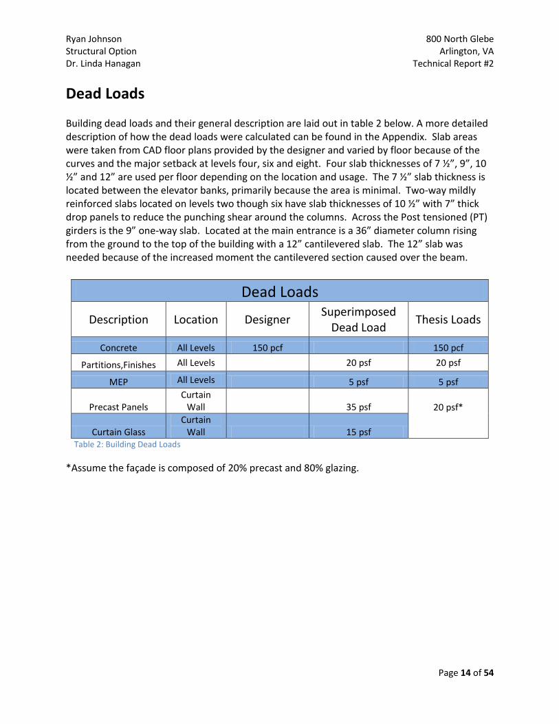
Dead Loads Building dead loads and their general description are laid out in table 2 below. A more detailed description of how the dead loads were calculated can be found in the Appendix. Slab areas were taken from CAD floor plans provided by the designer and varied by floor because of the curves and the major setback at levels four, six and eight. Four slab thicknesses of 7 ½”, 9”, 10 ½” and 12” are used per floor depending on the location and usage. The 7 ½” slab thickness is located between the elevator banks, primarily because the area is minimal. Two-way mildly reinforced slabs located on levels two though six have slab thicknesses of 10 ½” with 7” thick drop panels to reduce the punching shear around the columns. Across the Post tensioned (PT) girders is the 9” one-way slab. Located at the main entrance is a 36” diameter column rising from the ground to the top of the building with a 12” cantilevered slab. The 12” slab was needed because of the increased moment the cantilevered section caused over the beam.
Dead Loads
Description Location Designer Superimposed
Dead Load Thesis Loads
Concrete All Levels 150 pcf 150 pcf
Partitions,Finishes All Levels 20 psf 20 psf
MEP All Levels 5 psf 5 psf
Precast Panels Curtain
Wall 35 psf 20 psf*
Curtain Glass Curtain
Wall 15 psf Table 2: Building Dead Loads *Assume the façade is composed of 20% precast and 80% glazing.
Ryan Johnson 800 North Glebe Structural Option Arlington, VA Dr. Linda Hanagan Technical Report #2
Page 15 of 54
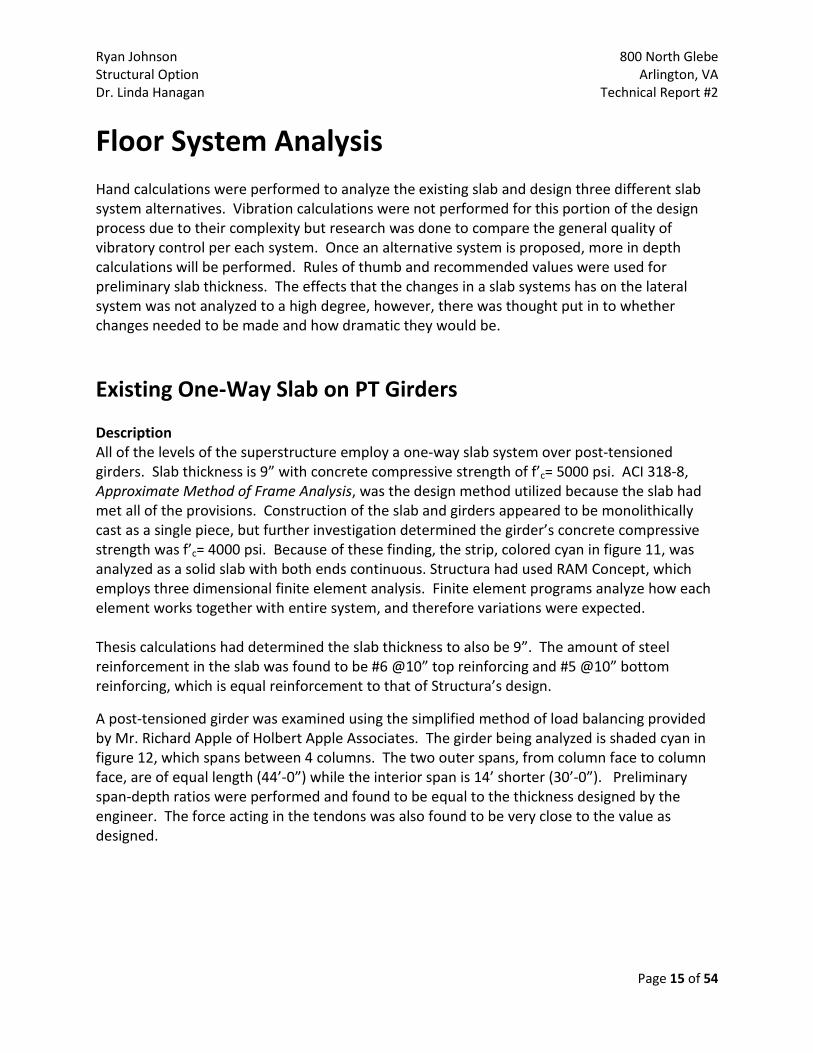
Floor System Analysis Hand calculations were performed to analyze the existing slab and design three different slab system alternatives. Vibration calculations were not performed for this portion of the design process due to their complexity but research was done to compare the general quality of vibratory control per each system. Once an alternative system is proposed, more in depth calculations will be performed. Rules of thumb and recommended values were used for preliminary slab thickness. The effects that the changes in a slab systems has on the lateral system was not analyzed to a high degree, however, there was thought put in to whether changes needed to be made and how dramatic they would be.
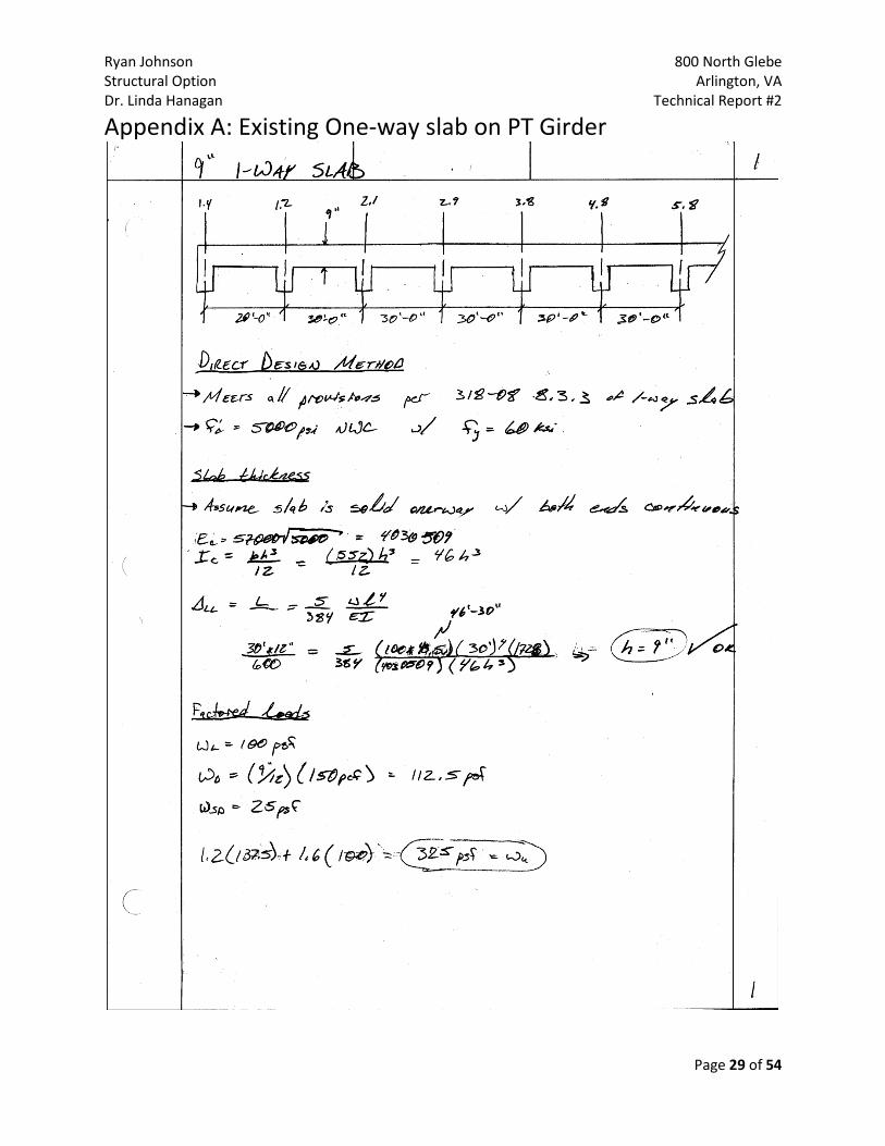
Existing One-Way Slab on PT Girders Description All of the levels of the superstructure employ a one-way slab system over post-tensioned girders. Slab thickness is 9” with concrete compressive strength of f’c= 5000 psi. ACI 318-8, Approximate Method of Frame Analysis, was the design method utilized because the slab had met all of the provisions. Construction of the slab and girders appeared to be monolithically cast as a single piece, but further investigation determined the girder’s concrete compressive strength was f’c= 4000 psi. Because of these finding, the strip, colored cyan in figure 11, was analyzed as a solid slab with both ends continuous. Structura had used RAM Concept, which employs three dimensional finite element analysis. Finite element programs analyze how each element works together with entire system, and therefore variations were expected. Thesis calculations had determined the slab thickness to also be 9”. The amount of steel reinforcement in the slab was found to be #6 @10” top reinforcing and #5 @10” bottom reinforcing, which is equal reinforcement to that of Structura’s design.
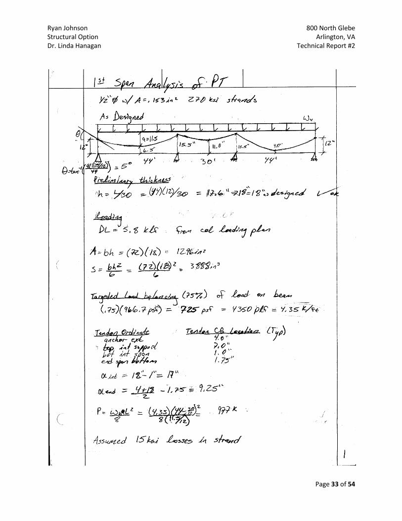
A post-tensioned girder was examined using the simplified method of load balancing provided by Mr. Richard Apple of Holbert Apple Associates. The girder being analyzed is shaded cyan in figure 12, which spans between 4 columns. The two outer spans, from column face to column face, are of equal length (44’-0”) while the interior span is 14’ shorter (30’-0”). Preliminary span-depth ratios were performed and found to be equal to the thickness designed by the engineer. The force acting in the tendons was also found to be very close to the value as designed.

Ryan Johnson 800 North Glebe Structural Option Arlington, VA Dr. Linda Hanagan Technical Report #2
Page 16 of 54
Figure 12: Post-tensioned Girder
Figure 11: One-Way Slab Strip
Advantages A one-way normally reinforced slab over shallow-wide post-tensioned girders allows for greater bay sizes. The post-tensioned girders spanning 46’ do not require any modification to the column grid and therefore, no architectural floor plan modifications need to be made. Post tensioning beams include a built-in camber which helps with deflection and vibration control. In the case of abnormal or catastrophic loading, the integrity of the building is still very high because the tendons act to resist sudden load increase. The one-way normally reinforced slab is able to span the short 30’ direction, decreasing the slab thickness and amount of reinforcement needed. Disadvantages Post-tensioned concrete undergoes more shortening of length compared to reinforced concrete. This shortening affects the deflection and also the actually length of the member. At high temperatures tensioning strands lose their strength faster than regularly reinforcement. This means that concrete cover much be greater to resist the extreme temperatures. The slab will shorten at a different rate, which may lead to cracking between the beams and slab face. Post-tensioned construction requires contractors with specialized skills. Often this will affect the cost and construction time for the project. Lead time for construction will also be affected by all of the slabs being constructed of concrete. It has been concluded that the existing post-tensioned girders and one-way normally reinforced slab system is feasible for thesis design. Further modeling investigation will be performed on this system for the proposal.

Ryan Johnson 800 North Glebe Structural Option Arlington, VA Dr. Linda Hanagan Technical Report #2
Page 17 of 54
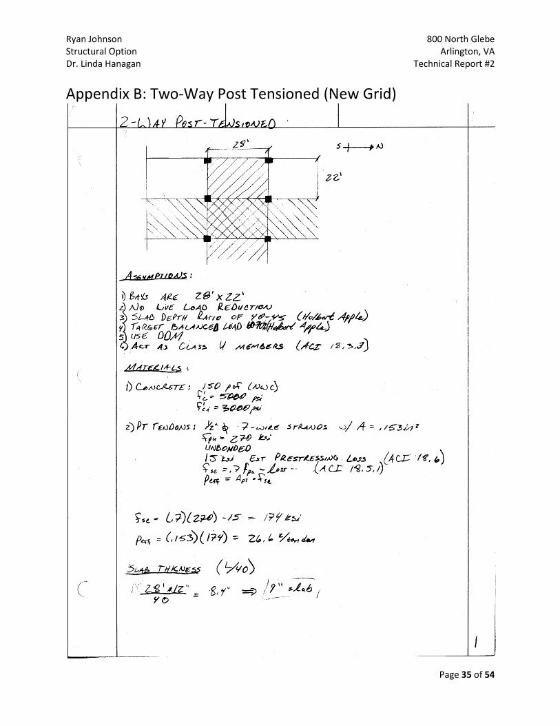
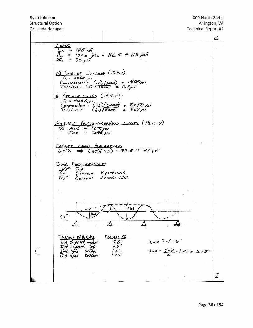
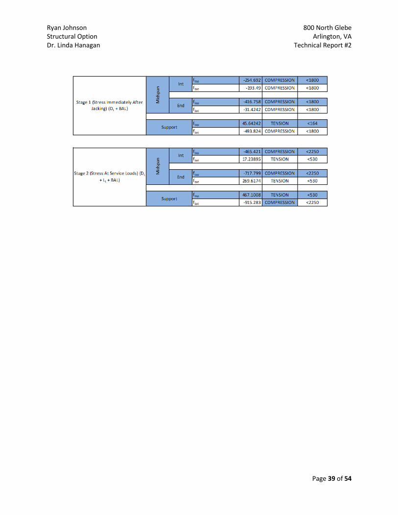
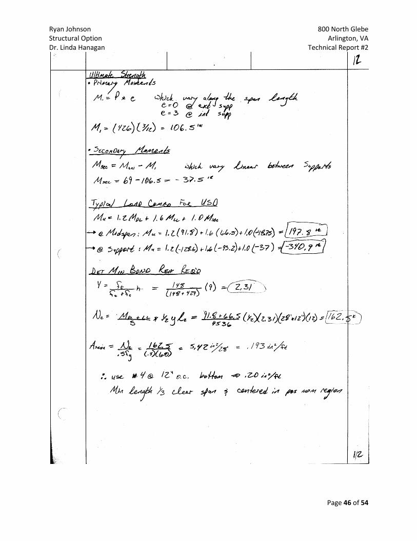
2-Way Posted-Tensioned Slab (New Grid) Description A new grid layout, 22’x28’, was used to analyze a two-way post-tensioned floor slab system with a parabolic tendon profile, while keeping the same column size for preliminary design (figures 13, a-d). An example from the Portland Cement Association (PCA) aided in calculating the necessary slab thickness and reinforcement needed. A conservative span to depth ratio of 40 was chosen, resulting in an initial slab thickness of 9”. ½” diameter, 7-strand tendons with an fpu= 270 ksi were used. It was determined that 20 tendons were needed in the North-South (28’) direction and 16 tendons in the East-West (22’) direction. Each tendon provided 26.6 kips resistance. Tendons running East-West are to be banded and uniformly distributed in the North-South direction. This decision was chosen because it allows the banded tendons to run the length of the building and has shown to work best for tendon placement at openings. Where large openings are to be encountered, elevator banks and stair towers, dead end anchors may be implemented. The lateral system will need to be altered to account for the variation in load transfer because of the two-way system. In addition to the post-tensioned reinforcement, mild reinforcement was determined to be required. At the first interior support, where the moment is greatest, 8 #5 reinforcing bars in the North-South and 12 #4 bars in the East-West direction are required, and #5 bars at 10” are required North-South and #4 at 12” East-West, for the most extreme positive moment regions. All IBC 2006 cover requirements were met to obtain a two hour fire rating, with no additional fireproofing needed for the slab. Design calculation to support findings may be found in the Appendix.

Ryan Johnson 800 North Glebe Structural Option Arlington, VA Dr. Linda Hanagan Technical Report #2
Page 18 of 54
Figure 13(a-d): New column grid layout for level 3,5,8,10
Ryan Johnson 800 North Glebe Structural Option Arlington, VA Dr. Linda Hanagan Technical Report #2
Page 19 of 54
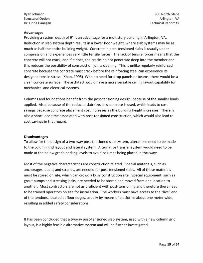
Advantages Providing a system depth of 9” is an advantage for a multistory building in Arlington, VA. Reduction in slab system depth results in a lower floor weight, where slab systems may be as much as half the entire building weight. Concrete in post-tensioned slabs is usually under compression and experiences very little tensile forces. The lack of tensile forces means that the concrete will not crack, and if it does, the cracks do not penetrate deep into the member and this reduces the possibility of construction joints opening. This is unlike regularly reinforced concrete because the concrete must crack before the reinforcing steel can experience its designed tensile stress. (Khan, 1995) With no need for drop panels or beams, there would be a clean concrete surface. The architect would have a more versatile ceiling layout capability for mechanical and electrical systems. Columns and foundations benefit from the post-tensioning design, because of the smaller loads applied. Also, because of the reduced slab size, less concrete is used, which leads to cost savings because concrete placement cost increases as the building height increases. There is also a short lead time associated with post-tensioned construction, which would also lead to cost savings in that regard. Disadvantages To allow for the design of a two-way post-tensioned slab system, alterations need to be made to the column grid layout and lateral system. Alternative transfer system would need to be made at the below grade parking levels to avoid columns being placed in thruways. Most of the negative characteristics are construction related. Special materials, such as anchorages, ducts, and strands, are needed for post tensioned slabs. All of these materials must be stored on site, which can crowd a busy construction site. Special equipment, such as grout pumps and stressing jacks, are needed to be stored and moved from one location to another. Most contractors are not as proficient with post-tensioning and therefore there need to be trained operators on site for installation. The workers must have access to the “live” end of the tendons, located at floor edges, usually by means of platforms about one meter wide, resulting in added safety considerations. It has been concluded that a two-ay post-tensioned slab system, used with a new column grid layout, is a highly feasible alternative system and will be further investigated.

Ryan Johnson 800 North Glebe Structural Option Arlington, VA Dr. Linda Hanagan Technical Report #2
Page 20 of 54
2-Way Posted-Tensioned Slab (Existing Grid) Description Post-tensioned slab design was also preformed on the existing column grid layout (figures 14, a-d). This was done to determine if alterations were not needed to implement a post-tensioned system. Calculations had determined that with a span to depth ratio of 40 the resulting initial slab thickness would need to be 14”. Using the initial thickness of 14” for the North-South direction, the actual precompression stress calculated (581 psi) is 93% greater than the recommended maximum value of 300 psi for floor slabs. The number of tendons required would be 110 distributed over the slab width. For the actual precompression stress to be within the recommended values, the slab thickness would need to be 28” thick. This is far too large of a stress increase, number of required tendon and slab thickness to be a feasible option. The East-West direction did not have the same complications regarding stress distribution. The actual precompression stress was calculated to be 248 psi, which is within the recommended values. The immense increase in building weight would cause a dramatic change needed to the lateral system. The story forces would become significantly larger, and the current double “C” shear wall design would be inadequate. The slab itself would offer partial resistance, but the stair tower walls may need to resist portions of the shear force as well. Supporting calculation may be found in the Appendix.

Ryan Johnson 800 North Glebe Structural Option Arlington, VA Dr. Linda Hanagan Technical Report #2
Page 21 of 54
Figure 14 (a-d): existing column grid layout for levels 3,5,8,10

Ryan Johnson 800 North Glebe Structural Option Arlington, VA Dr. Linda Hanagan Technical Report #2
Page 22 of 54
Advantages Advantages for implementing a two-way post-tensioned floor slab system, using the current column grid layout, are that no alterations would be needed for the architectural floor plans. If the North-South forces were able to be minimized to a reasonable value, few changes would be needed for the rest of the structural systems. The substructure would be adequately laid out and footings properly located. Other advantages are similar to those of the two-way post-tensioned system with a new column grid layout. Few tensile stresses would be acting in the concrete and therefore, minimize cracking. Disadvantages For the actual precompression stress to be within the recommended values, while having a 24” slab thickness, would require a significant amount of concrete. Each floor would need approximately 450 cubic yards of concrete compared to the approximate 200 cubic yards that would currently exist with the designed one-way slab. Formwork to support two feet (300 psf) of concrete may become very expensive and cumbersome to move from floor to floor. Other disadvantages to include are the construction requires contractors who are trained and knowledgeable on slab post-tensioning. Without altering the two-way design significantly, the post-tensioned system with the current column grid layout is not a feasible alternative slab system. The slab thickness is far too thick to be beneficial.

Ryan Johnson 800 North Glebe Structural Option Arlington, VA Dr. Linda Hanagan Technical Report #2
Page 23 of 54
Hollow Core Precast Planks on Steel Framing Description The hollow core precast concrete plank system was studied to be implemented on the modified 28’x22’ bay. The precast planks are offered in 4’-0” width increments and this was a leading cause of the bay size modification. An interior bay on the office level was used in analysis and is shown in figure 15 below.
Figure 15: Interior bay used for hollow core plank design
Precast / Prestressed Concrete Institute, PCI Design Handbook was used for thesis design. It was determined a 6” thick plank with a 2” topping would meet the loading and span criteria the best. The 22’ span was achieved by implementing a 96-S plank. The designation of the slab describes the number of strands (9), the strand diameter (6/16), and the strand profile Straight). The hollow core system selected is capable of handling a uniform service load of 160 psf, which is greater than the 140 psf service load calculated. The supporting girder needed to for the hollow core planks was determined to be a W24x76. A beam of this depth could increase the overall system depth to 30”, which is 12” deeper than the current system. This was calculated using AISC Steel Construction Manual and hand calculation may be found in Appendix.

Ryan Johnson 800 North Glebe Structural Option Arlington, VA Dr. Linda Hanagan Technical Report #2
Page 24 of 54
Advantages A variety of advantages are available for a hollow core precast plank system. The most notable benefits are found in the construction process. Construction can take place throughout the entire year because there are no curing time or temperature requirements to erect the system. Construction speed is increased which allows for the future tenants to occupy the building, and in turn allows the owner to make a larger profit. The planks themselves are lightweight, durable and require minimal maintenance, while being a LEED rated noise attenuating system. Disadvantages To take advantage of a hollow-core plank system, alterations to the column grid would be needed and therefore, the architectural floor plans would be modified. Hollow core slabs are offered in 4’ width and so the column spacing must be multiples of 4’. Problems with relying on a uniform grid layout are the occurrences of openings and irregularities such as cantilevers. For the curved perimeter areas, specialty planks would be necessary, causing a considerable cost increase. The steel beam depths are considerably deeper than the previous post-tensioned beams. Switching from the existing concrete structure to a steel frame structure, consideration must be made to the lateral system. The implementation of moment connection would be the most efficient method to allow for open floor plans. Mechanical dampers would be difficult to employ because very few areas are hidden behind walls. Steel beams and columns would need to be fireproofed and longer time must be accounted for detailing, fabrication and transportation. It has been concluded that the hollow core planks over steel framing is not a feasible slab system alternative. Hollow core slabs offer a vast amount of advantages on a regularly shaped building, but is difficult to design for irregularities.
Ryan Johnson 800 North Glebe Structural Option Arlington, VA Dr. Linda Hanagan Technical Report #2
Page 25 of 54
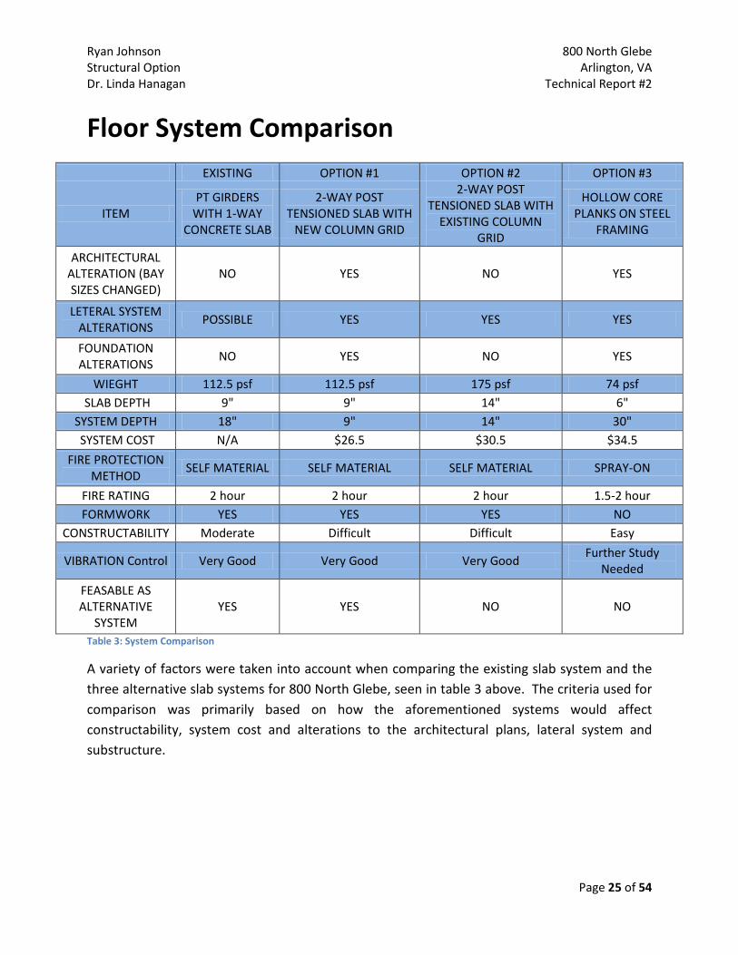
Floor System Comparison
EXISTING OPTION #1 OPTION #2 OPTION #3
ITEM PT GIRDERS
WITH 1-WAY CONCRETE SLAB
2-WAY POST TENSIONED SLAB WITH
NEW COLUMN GRID
2-WAY POST TENSIONED SLAB WITH
EXISTING COLUMN GRID
HOLLOW CORE PLANKS ON STEEL
FRAMING
ARCHITECTURAL ALTERATION (BAY SIZES CHANGED)
NO YES NO YES
LETERAL SYSTEM ALTERATIONS
POSSIBLE YES YES YES
FOUNDATION ALTERATIONS
NO YES NO YES
WIEGHT 112.5 psf 112.5 psf 175 psf 74 psf SLAB DEPTH 9" 9" 14" 6"
SYSTEM DEPTH 18" 9" 14" 30" SYSTEM COST N/A $26.5 $30.5 $34.5
FIRE PROTECTION METHOD
SELF MATERIAL SELF MATERIAL SELF MATERIAL SPRAY-ON
FIRE RATING 2 hour 2 hour 2 hour 1.5-2 hour FORMWORK YES YES YES NO
CONSTRUCTABILITY Moderate Difficult Difficult Easy
VIBRATION Control Very Good Very Good Very Good Further Study
Needed
FEASABLE AS ALTERNATIVE
SYSTEM YES YES NO NO
Table 3: System Comparison
A variety of factors were taken into account when comparing the existing slab system and the three alternative slab systems for 800 North Glebe, seen in table 3 above. The criteria used for comparison was primarily based on how the aforementioned systems would affect constructability, system cost and alterations to the architectural plans, lateral system and substructure.

Ryan Johnson 800 North Glebe Structural Option Arlington, VA Dr. Linda Hanagan Technical Report #2
Page 26 of 54
Constructability Three out of the four system are concrete, which is the material primarily used for high-rise buildings in and around Washington, DC. Many of the contractors in the area are familiar with concrete forming and pouring. However, post-tensioned slabs require a more specialized group to lay out the system efficiently. The equipment needed for post-tensioning would need to be stored on site and require alterations to the construction timeline to account for the contractor needing to stress the tendons after the concrete has obtained sufficient strength. The hollow core plank on steel framing is a very efficient construction process. Hollow core planks are cast off site and therefore, no lag time is needed to allow for the concrete to cure. However, there needs to be sufficient space on the site to store to planks may be difficult because of the location in downtown Arlington. The steel framing used to support the planks would also be easy to construct, but like the planks, a storage area may be needed for the steel members. At this time, based on the location and contractor experience, it is unknown which of the systems could be constructed the quickest. System Cost RS Means Assemblies Cost Data, 2009 was used to roughly estimate the slab system costs. A 10% increase was included, as recommended by RS Means, to account for contractor costs. The most expensive slab system designed was found to be the hollow core planks on steel framing system. The most inexpensive system was found to be the two-way post-tensioned slab system with the new column grid. However, the cost of adding more columns was not taken into account compared to the existing slab system grid. Information is still being researched regarding the one-way slab over post-tensioned girder cost per square foot. A more accurate cost analysis using RAM Concept will be performed when a system is proposed for future reports. Architectural Alterations Changing the column grid layout to a 28’x22’ would lead to alterations for the architectural floor plans. An attempt to locate the columns near partition walls was done, but some floor levels may need to alter cubical orientations. New columns were placed to line up the East-West column grid lines at 28’, and new grid lines were placed to cut the 46’ bay length in half. As designed, there are currently columns located in disadvantageous regions of offices and an architectural layout may be a proposed breadth.

Ryan Johnson 800 North Glebe Structural Option Arlington, VA Dr. Linda Hanagan Technical Report #2
Page 27 of 54
Along with alterations to the floor plans, ceiling plans will also need to be studied more in-depth. The current layout has 6’ shallow girders in the East-West direction, but the two-way post-tensioned slab would offer a smooth bottom surface with no obstacles for MEP. There was an attempt to keep the system depth under the current 18” design to not alter the 9’-0” floor-to-ceiling heights. The building is designed as class-A office space, and by lowering the ceiling height below 9’-0” would cause the classification to decrease and have a large impact on the profit the developer would make. The overall building height has been maxed out to the highest level allowed in the zoning region and cannot be increased. This being the case, systems being a probably alternative would be required to not alter the floor-to-ceiling heights. Lateral System Alterations The proposed two-way post-tensioned slab system with the new column grid would be a lighter floor slab system, due to a reduction in concrete per level. However, more columns are needed and may raise the overall building weight back up to the current design weight. Building weight plays an important role in determining the story shear force, and therefore the overall seismic base shear. Post-tensioned slabs are capable of transferring lateral forces but it is believed that the overall lateral system will need to be increased to include the stair tower walls. A system with more mass and stiffness would be more rigid and this is assumed to reduce vibrations and building seismic frequency. More research will be performed in order to determine which system reacts better to lateral system alterations. Foundation Alterations Columns run from the top level down to the substructure foundations. This is a major reason for the current column grid layout being the way it is currently designed. By adding two new column grid lines, transfer girders will most likely need to be designed for portions on the building that are overtop the below grade parking structure. Some of the current foundation sizes may be decreased because the load would be distributed differently, but additional foundations will be needed.

Ryan Johnson 800 North Glebe Structural Option Arlington, VA Dr. Linda Hanagan Technical Report #2
Page 28 of 54
Conclusion After comparing the aforementioned slab systems with regards to a multitude of criteria, it was an ultimate goal to determining which system would be a feasible alternative for 800 North Glebe. The findings from this report have concluded that the two-way post-tensioned slab system with a new column grid layout is the most feasible alternative to the current one-way slab system. The system would reduce the overall slab system depth, weight and possibly overall cost of the building. There is concerns regarding the construction of the two-way post-tensioned slab because of the intense labor and experience needed to safely and efficiently construct the system. However, there are many building contractors in the Virginia area that are experienced with post-tensioned construction. Since the architectural is a crucial part of the building design, whichever system is chosen for the final proposal must be sure to accommodate the geometry. Curves and radial lines can be seen throughout the building. Both the current slab system and post-tensioned slabs offer the ability to form the curves because the concrete will be cast-in-place. Post-tensioned tendon design employs balanced loading and therefore, vibrations and deflection may be reduced. In addition to these serviceability issues, the two-way post-tensioned slab offers a smooth surface with no beam intrusion, allowing mechanical, electrical and plumbing equipment to be arranged more freely and efficiently. The two other system analyzed were determined not to be feasible alternatives for the building. Two-way post-tensioned design with the existing column requires such a thick slab to meet stress limits, that any benefit the post-tensioning would offer would be lost in slab weight material costs. Hollow core planks over steel framing would also not be a feasible alternative. The overall slab system depth would require decreasing the floor-to-ceiling heights, and therefore, reduce the classification level of the office space. Also, hollow core planks require uniform bay layouts, which cannot be obtained in the building because of the curved design. Unlike the concrete slab systems, which do not require any additional fireproofing to meet the 2 hour rating, the steel beams will need to be fireproofed to meet the rating. From the information ascertained in the system comparisons, it has be determined that the two-way post-tensioned slab system shall be further investigated as a possible alternative slab system to be proposed for AE Thesis.
Ryan Johnson 800 North Glebe Structural Option Arlington, VA Dr. Linda Hanagan Technical Report #2
Page 29 of 54
Appendix A: Existing One-way slab on PT Girder

Ryan Johnson 800 North Glebe Structural Option Arlington, VA Dr. Linda Hanagan Technical Report #2
Page 30 of 54

Ryan Johnson 800 North Glebe Structural Option Arlington, VA Dr. Linda Hanagan Technical Report #2
Page 31 of 54
[Type a quote from the document or the summary of an interesting point. You can position the text box anywhere in the document. Use the Text Box Tools tab to change the formatting of the pull quote text box.]

Ryan Johnson 800 North Glebe Structural Option Arlington, VA Dr. Linda Hanagan Technical Report #2
Page 32 of 54
THESE VALUES MATCH THOSE OF THE ENGINEER
Ryan Johnson 800 North Glebe Structural Option Arlington, VA Dr. Linda Hanagan Technical Report #2
Page 33 of 54

Ryan Johnson 800 North Glebe Structural Option Arlington, VA Dr. Linda Hanagan Technical Report #2
Page 34 of 54
Ryan Johnson 800 North Glebe Structural Option Arlington, VA Dr. Linda Hanagan Technical Report #2
Page 35 of 54
Appendix B: Two-Way Post Tensioned (New Grid)
Ryan Johnson 800 North Glebe Structural Option Arlington, VA Dr. Linda Hanagan Technical Report #2
Page 36 of 54

Ryan Johnson 800 North Glebe Structural Option Arlington, VA Dr. Linda Hanagan Technical Report #2
Page 37 of 54

Ryan Johnson 800 North Glebe Structural Option Arlington, VA Dr. Linda Hanagan Technical Report #2
Page 38 of 54
Ryan Johnson 800 North Glebe Structural Option Arlington, VA Dr. Linda Hanagan Technical Report #2
Page 39 of 54

Ryan Johnson 800 North Glebe Structural Option Arlington, VA Dr. Linda Hanagan Technical Report #2
Page 40 of 54

Ryan Johnson 800 North Glebe Structural Option Arlington, VA Dr. Linda Hanagan Technical Report #2
Page 41 of 54

Ryan Johnson 800 North Glebe Structural Option Arlington, VA Dr. Linda Hanagan Technical Report #2
Page 42 of 54

Ryan Johnson 800 North Glebe Structural Option Arlington, VA Dr. Linda Hanagan Technical Report #2
Page 43 of 54

Ryan Johnson 800 North Glebe Structural Option Arlington, VA Dr. Linda Hanagan Technical Report #2
Page 44 of 54

Ryan Johnson 800 North Glebe Structural Option Arlington, VA Dr. Linda Hanagan Technical Report #2
Page 45 of 54
Ryan Johnson 800 North Glebe Structural Option Arlington, VA Dr. Linda Hanagan Technical Report #2
Page 46 of 54

Ryan Johnson 800 North Glebe Structural Option Arlington, VA Dr. Linda Hanagan Technical Report #2
Page 47 of 54

Ryan Johnson 800 North Glebe Structural Option Arlington, VA Dr. Linda Hanagan Technical Report #2
Page 48 of 54
Ryan Johnson 800 North Glebe Structural Option Arlington, VA Dr. Linda Hanagan Technical Report #2
Page 49 of 54
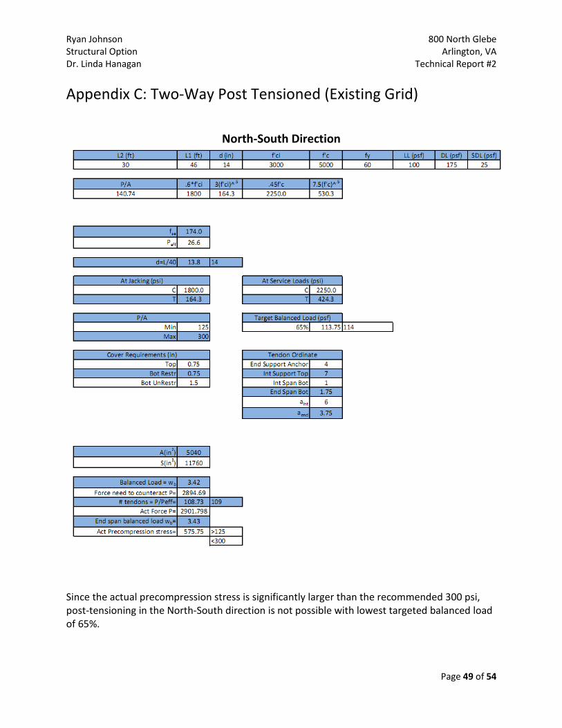
Appendix C: Two-Way Post Tensioned (Existing Grid)
North-South Direction
Since the actual precompression stress is significantly larger than the recommended 300 psi, post-tensioning in the North-South direction is not possible with lowest targeted balanced load of 65%.

Ryan Johnson 800 North Glebe Structural Option Arlington, VA Dr. Linda Hanagan Technical Report #2
Page 50 of 54
East-West Direction

Ryan Johnson 800 North Glebe Structural Option Arlington, VA Dr. Linda Hanagan Technical Report #2
Page 51 of 54
The minimum bond reinforcement shows that no reinforcing is necessary because the calculated ft is less than 2√f'c. (ACI 18.9.3.2)

Ryan Johnson 800 North Glebe Structural Option Arlington, VA Dr. Linda Hanagan Technical Report #2
Page 52 of 54
Appendix D: Hollow Core Precast on Steel

Ryan Johnson 800 North Glebe Structural Option Arlington, VA Dr. Linda Hanagan Technical Report #2
Page 53 of 54

Ryan Johnson 800 North Glebe Structural Option Arlington, VA Dr. Linda Hanagan Technical Report #2
Page 54 of 54
References American Concrete Institute, 2008, Building Code Requirements for Structural Concrete and Commentary, ACI 318-08, Farmington Hills, MI
American Institute of Steel Construction, Inc., 2005, Steel Construction Manual, 13th Edition, Chicago, IL
American Society of Civil Engineers, 2005, Minimum Design Loads for Buildings and Other Structures, ASCE 7-05, Reston, VA
Khan, S; Williams, S, 1995, Post-Tensioned Concrete Floors, Butterworth-Heinemann, Oxford, Great Britain
Nilson, A; Darwin, D. and Dolan, C., 2004, Design of Concrete Structures, 13th Edition, McGraw Hill, New York, NY
Precast/ Prestressed Concrete Institute, 1999, PCI Design Handbook, 6th Edition, Chicago, IL
RSMeans, 2009, Assemblies Cost Data, 34th Edition, Reed Construction Data, Kinston, MA