8000gs_clig
TRANSCRIPT
613-001020 Rev. A
ManagementSoftware
AT-S95
CLI User’s GuideAT-8000GS Series Stackable Gigabit Ethernet Switches
Version 1.0.1

Copyright © 2008 Allied Telesis, Inc. All rights reserved. No part of this publication may be reproduced without prior written permission from Allied Telesis, Inc.Allied Telesis is a trademark of Allied Telesis, Inc. Microsoft and Internet Explorer are registered trademarks of Microsoft Corporation. Netscape Navigator is a registered trademark of Netscape Communications Corporation. All other product names, company names, logos or other designations mentioned herein are trademarks or registered trademarks of their respective owners.Allied Telesis, Inc. reserves the right to make changes in specifications and other information contained in this document without prior written notice. The information provided herein is subject to change without notice. In no event shall Allied Telesis, Inc. be liable for any incidental, special, indirect, or consequential damages whatsoever, including but not limited to lost profits, arising out of or related to this manual or the information contained herein, even if Allied Telesis, Inc. has been advised of, known, or should have known, the possibility of such damages.
Table of Contents
Preface ................................................................................................................................... 1Intended Audience...........................................................................................................................2Document Conventions ...................................................................................................................3Contacting Allied Telesis .................................................................................................................4
Chapter 1.Using the CLI ....................................................................................................... 5Overview ................................................................................................................................................5
CLI Command Modes......................................................................................................................5Introduction ................................................................................................................................................5User EXEC Mode ......................................................................................................................................5Privileged EXEC Mode ..............................................................................................................................5Global Configuration Mode ........................................................................................................................6Interface Configuration and Specific Configuration Modes........................................................................7
Starting the CLI................................................................................................................................8Editing Features ..............................................................................................................................9
Entering Commands ..................................................................................................................................9Terminal Command Buffer ...................................................................................................................9Negating the Effect of Commands .....................................................................................................10Command Completion........................................................................................................................10Nomenclature .....................................................................................................................................10Keyboard Shortcuts............................................................................................................................10CLI Command Conventions ...............................................................................................................11
Copying and Pasting Text........................................................................................................................11
Chapter 2.ACL Commands ................................................................................................ 13ip access-list.........................................................................................................................................13permit (ip) .............................................................................................................................................13deny (IP)...............................................................................................................................................16mac access-list.....................................................................................................................................18permit (MAC)........................................................................................................................................19deny (MAC) ..........................................................................................................................................20service-acl ............................................................................................................................................21show access-lists .................................................................................................................................22show interfaces access-lists.................................................................................................................22
Chapter 3.AAA Commands ................................................................................................ 24aaa authentication login .......................................................................................................................24aaa authentication enable ....................................................................................................................25login authentication ..............................................................................................................................26enable authentication ...........................................................................................................................27ip http authentication ............................................................................................................................27
Page i

Allied Telesis Command Line Interface User’s Guide
ip https authentication.......................................................................................................................... 28show authentication methods .............................................................................................................. 29password ............................................................................................................................................. 30username............................................................................................................................................. 30show users accounts ........................................................................................................................... 31enable password ................................................................................................................................. 32
Chapter 4.Address Table Commands ............................................................................... 34bridge address..................................................................................................................................... 34bridge multicast filtering....................................................................................................................... 34bridge multicast address...................................................................................................................... 35bridge multicast forbidden address...................................................................................................... 36bridge multicast forward-all.................................................................................................................. 37bridge multicast forbidden forward-all.................................................................................................. 38bridge aging-time................................................................................................................................. 38clear bridge.......................................................................................................................................... 39port security ......................................................................................................................................... 39port security mode ............................................................................................................................... 40port security max ................................................................................................................................. 41port security routed secure-address .................................................................................................... 41show bridge address-table .................................................................................................................. 42show bridge address-table static ......................................................................................................... 43show bridge address-table count......................................................................................................... 44show bridge multicast address-table ................................................................................................... 45show bridge multicast address-table static.......................................................................................... 47show bridge multicast filtering ............................................................................................................. 47show ports security.............................................................................................................................. 49show ports security addresses ............................................................................................................ 50
Chapter 5.Clock Commands.............................................................................................. 52clock set............................................................................................................................................... 52clock source......................................................................................................................................... 52clock timezone..................................................................................................................................... 53clock summer-time .............................................................................................................................. 54sntp authentication-key........................................................................................................................ 55sntp authenticate ................................................................................................................................. 56sntp trusted-key ................................................................................................................................... 56sntp client poll timer............................................................................................................................. 57sntp broadcast client enable................................................................................................................ 57sntp anycast client enable ................................................................................................................... 58sntp client enable (Interface) ............................................................................................................... 59sntp unicast client enable .................................................................................................................... 59sntp unicast client poll ......................................................................................................................... 60sntp server........................................................................................................................................... 60show clock ........................................................................................................................................... 61show sntp configuration....................................................................................................................... 62show sntp status.................................................................................................................................. 63
Page ii
Not approved by Document Control. For review only.
Chapter 6.Configuration and Image File Commands ...................................................... 65copy......................................................................................................................................................65dir .........................................................................................................................................................67delete ...................................................................................................................................................68boot system..........................................................................................................................................69show running-config .............................................................................................................................69show startup-config ..............................................................................................................................70show bootvar........................................................................................................................................71
Chapter 7.DHCP Option 82 Commands ............................................................................ 72ip dhcp information option ....................................................................................................................72show ip dhcp information option...........................................................................................................72ip dhcp relay enable .............................................................................................................................73
Chapter 8.DHCP Snooping Commands ............................................................................ 74ip dhcp snooping..................................................................................................................................74ip dhcp snooping vlan ..........................................................................................................................74ip dhcp snooping trust ..........................................................................................................................75ip dhcp snooping information option allowed-untrusted .......................................................................76ip dhcp snooping verify ........................................................................................................................76ip dhcp snooping database ..................................................................................................................77ip dhcp snooping database update-freq...............................................................................................77ip dhcp snooping binding .....................................................................................................................78clear ip dhcp snooping database .........................................................................................................79show ip dhcp snooping.........................................................................................................................79show ip dhcp snooping binding ............................................................................................................80
Chapter 9.Ethernet Configuration Commands................................................................. 82interface ethernet .................................................................................................................................82interface range ethernet .......................................................................................................................82shutdown..............................................................................................................................................83description............................................................................................................................................84speed ...................................................................................................................................................84duplex...................................................................................................................................................85negotiation............................................................................................................................................86flowcontrol ............................................................................................................................................86mdix......................................................................................................................................................87back-pressure ......................................................................................................................................88port jumbo-frame..................................................................................................................................88system flowcontrol................................................................................................................................89clear counters.......................................................................................................................................89set interface active ...............................................................................................................................90show interfaces advertise.....................................................................................................................90show interfaces configuration...............................................................................................................91show interfaces status..........................................................................................................................93show interfaces description..................................................................................................................94show ports jumbo-frame.......................................................................................................................95
Page iii
Allied Telesis Command Line Interface User’s Guide
show interfaces counters..................................................................................................................... 95show system flowcontrol...................................................................................................................... 99port storm-control include-multicast (IC).............................................................................................. 99port storm-control broadcast enable.................................................................................................. 100port storm-control broadcast rate ...................................................................................................... 101show ports storm-control ................................................................................................................... 102
Chapter 10.GVRP Commands.......................................................................................... 103gvrp enable (Global) .......................................................................................................................... 103gvrp enable (Interface) ...................................................................................................................... 103garp timer .......................................................................................................................................... 104gvrp vlan-creation-forbid.................................................................................................................... 105gvrp registration-forbid....................................................................................................................... 105clear gvrp statistics ............................................................................................................................ 106show gvrp configuration..................................................................................................................... 106show gvrp statistics ........................................................................................................................... 107show gvrp error-statistics................................................................................................................... 108
Chapter 11.IGMP Snooping Commands ......................................................................... 110ip igmp snooping (Global).................................................................................................................. 110ip igmp snooping (Interface) .............................................................................................................. 110ip igmp snooping mrouter learn-pim-dvmrp....................................................................................... 111ip igmp snooping host-time-out ......................................................................................................... 112ip igmp snooping querier enable ....................................................................................................... 112ip igmp snooping querier address ..................................................................................................... 113ip igmp snooping querier version....................................................................................................... 114ip igmp snooping mrouter-time-out.................................................................................................... 114ip igmp snooping leave-time-out........................................................................................................ 115show ip igmp snooping mrouter......................................................................................................... 116show ip igmp snooping interface ....................................................................................................... 117show ip igmp snooping groups .......................................................................................................... 118
Chapter 12.IP Addressing Commands............................................................................ 119ip address .......................................................................................................................................... 119ip address dhcp ................................................................................................................................. 119ip default-gateway ............................................................................................................................. 120show ip interface................................................................................................................................ 121arp ..................................................................................................................................................... 122arp timeout......................................................................................................................................... 122clear arp-cache.................................................................................................................................. 123show arp ............................................................................................................................................ 124ip domain-lookup............................................................................................................................. 124ip domain-name................................................................................................................................. 125ip name-server................................................................................................................................... 126ip domain-name................................................................................................................................. 126ip name-server................................................................................................................................... 127ip host ................................................................................................................................................ 127
Page iv
Not approved by Document Control. For review only.
clear host............................................................................................................................................128clear host dhcp...................................................................................................................................129show hosts .........................................................................................................................................129
Chapter 13.Line Commands ............................................................................................ 131line......................................................................................................................................................131speed .................................................................................................................................................131autobaud ............................................................................................................................................132exec-timeout.......................................................................................................................................133history.................................................................................................................................................133history size .........................................................................................................................................134terminal history...................................................................................................................................134terminal history size ...........................................................................................................................135show line ............................................................................................................................................135
Section 14.LACP Commands........................................................................................... 138lacp system-priority ............................................................................................................................138lacp port-priority .................................................................................................................................139lacp timeout........................................................................................................................................140show lacp ethernet .............................................................................................................................141show lacp port-channel ......................................................................................................................143
Chapter 15.Management ACL Commands ..................................................................... 144management access-list ....................................................................................................................144permit (Management).........................................................................................................................145deny (Management) ...........................................................................................................................146management access-class.................................................................................................................146show management access-list ...........................................................................................................147show management access-class .......................................................................................................148
Chapter 16.PHY Diagnostics Commands ....................................................................... 149test copper-port tdr.............................................................................................................................149show copper-ports tdr ........................................................................................................................149show copper-ports cable-length .........................................................................................................150
Chapter 17.Port Channel Commands ............................................................................. 152interface port-channel ........................................................................................................................152interface range port-channel ..............................................................................................................152channel-group ....................................................................................................................................153show interfaces port-channel .............................................................................................................153
Chapter 18.Port Monitor Commands .............................................................................. 155port monitor ........................................................................................................................................155show ports monitor.............................................................................................................................156
Chapter 19.Power over Ethernet Commands................................................................. 157power inline ........................................................................................................................................157
Page v

Allied Telesis Command Line Interface User’s Guide
power inline powered-device ............................................................................................................. 157power inline priority............................................................................................................................ 158power inline usage-threshold............................................................................................................. 159power inline traps enable................................................................................................................... 159show power inline .............................................................................................................................. 160
Chapter 20.QoS Commands ............................................................................................ 164qos..................................................................................................................................................... 164show qos ........................................................................................................................................... 164priority-queue out num-of-queues ..................................................................................................... 165rate-limit............................................................................................................................................. 165traffic-shape....................................................................................................................................... 166show qos interface............................................................................................................................. 166wrr-queue cos-map............................................................................................................................ 167qos trust(Global) ................................................................................................................................ 168qos map dscp-queue ......................................................................................................................... 169qos cos .............................................................................................................................................. 170show qos map ................................................................................................................................... 170
Chapter 21.Radius Commands........................................................................................ 172radius-server host.............................................................................................................................. 172radius-server key ............................................................................................................................... 173radius-server retransmit..................................................................................................................... 173radius-server source-ip...................................................................................................................... 174radius-server timeout......................................................................................................................... 175radius-server deadtime...................................................................................................................... 175show radius-servers .......................................................................................................................... 176
Chapter 22.RMON Commands......................................................................................... 178show rmon statistics .......................................................................................................................... 178rmon collection history....................................................................................................................... 180show rmon collection history ............................................................................................................. 180show rmon history ............................................................................................................................. 181rmon alarm ........................................................................................................................................ 184show rmon alarm-table ...................................................................................................................... 185show rmon alarm ............................................................................................................................... 186rmon event......................................................................................................................................... 187show rmon events ............................................................................................................................. 188show rmon log ................................................................................................................................... 189rmon table-size .................................................................................................................................. 190
Chapter 23.SNMP Commands ......................................................................................... 192snmp-server community .................................................................................................................... 192snmp-server view .............................................................................................................................. 193snmp-server group ............................................................................................................................ 194snmp-server user............................................................................................................................... 194snmp-server engineID local............................................................................................................... 196
Page vi
Not approved by Document Control. For review only.
snmp-server enable traps ..................................................................................................................197snmp-server filter ...............................................................................................................................197snmp-server host ...............................................................................................................................198snmp-server v3-host ..........................................................................................................................199snmp-server trap authentication.........................................................................................................200snmp-server contact...........................................................................................................................201snmp-server location..........................................................................................................................201snmp-server set .................................................................................................................................202show snmp.........................................................................................................................................203show snmp engineid ..........................................................................................................................204show snmp views...............................................................................................................................205show snmp groups .............................................................................................................................205show snmp filters ...............................................................................................................................206show snmp users ...............................................................................................................................207
Chapter 24.Spanning-Tree Commands........................................................................... 208spanning-tree .....................................................................................................................................208spanning-tree mode ...........................................................................................................................208spanning-tree forward-time ................................................................................................................209spanning-tree hello-time.....................................................................................................................209spanning-tree max-age ......................................................................................................................210spanning-tree priority .........................................................................................................................211spanning-tree disable.........................................................................................................................211spanning-tree cost..............................................................................................................................212spanning-tree port-priority ..................................................................................................................213spanning-tree portfast ........................................................................................................................213spanning-tree link-type.......................................................................................................................214spanning-tree pathcost method..........................................................................................................214spanning-tree bpdu ............................................................................................................................215spanning-tree guard root....................................................................................................................216spanning-tree bpduguard ...................................................................................................................216clear spanning-tree detected-protocols..............................................................................................217spanning-tree mst priority...................................................................................................................217spanning-tree mst max-hops..............................................................................................................218spanning-tree mst port-priority ...........................................................................................................218spanning-tree mst cost.......................................................................................................................219spanning-tree mst configuration.........................................................................................................220instance (mst).....................................................................................................................................220name (mst) .........................................................................................................................................221revision (mst)......................................................................................................................................222show (mst)..........................................................................................................................................222exit (mst) ............................................................................................................................................223abort (mst)..........................................................................................................................................224show spanning-tree............................................................................................................................224
Chapter 25.SSH Commands ............................................................................................ 236ip ssh port...........................................................................................................................................236
Page vii
Allied Telesis Command Line Interface User’s Guide
ip ssh server ...................................................................................................................................... 236crypto key generate dsa .................................................................................................................... 237crypto key generate rsa ..................................................................................................................... 237ip ssh pubkey-auth ............................................................................................................................ 238crypto key pubkey-chain ssh ............................................................................................................. 238user-key............................................................................................................................................. 239key-string ........................................................................................................................................... 240show ip ssh........................................................................................................................................ 241show crypto key mypubkey ............................................................................................................... 242show crypto key pubkey-chain ssh.................................................................................................... 243
Chapter 26.Syslog Commands........................................................................................ 245logging on .......................................................................................................................................... 245logging ............................................................................................................................................... 245logging console.................................................................................................................................. 246logging buffered................................................................................................................................. 247logging buffered size ......................................................................................................................... 247clear logging ...................................................................................................................................... 248logging file ......................................................................................................................................... 249clear logging file................................................................................................................................. 249aaa logging ........................................................................................................................................ 250file-system logging............................................................................................................................. 250management logging ......................................................................................................................... 251show logging...................................................................................................................................... 252show logging file ................................................................................................................................ 254show syslog-servers .......................................................................................................................... 256
Chapter 27.TACACS+ Commands................................................................................... 258tacacs-server host ............................................................................................................................. 258tacacs-server key .............................................................................................................................. 259tacacs-server timeout ........................................................................................................................ 259tacacs-server source-ip ..................................................................................................................... 260show tacacs....................................................................................................................................... 260
Chapter 28.System Management Commands................................................................ 262ping.................................................................................................................................................... 262reload................................................................................................................................................. 264resume............................................................................................................................................... 264hostname........................................................................................................................................... 265stack master ...................................................................................................................................... 265stack reload ....................................................................................................................................... 266stack change unit-id........................................................................................................................... 267show stack......................................................................................................................................... 267show users ........................................................................................................................................ 269show sessions ................................................................................................................................... 270show system...................................................................................................................................... 271show system id .................................................................................................................................. 272
Page viii
Not approved by Document Control. For review only.
show version ......................................................................................................................................273set system..........................................................................................................................................275
Chapter 29.User Interface Commands............................................................................ 276enable ................................................................................................................................................276disable................................................................................................................................................276login....................................................................................................................................................277configure ............................................................................................................................................277exit (Configuration).............................................................................................................................278exit......................................................................................................................................................278end .....................................................................................................................................................279help ....................................................................................................................................................279terminal datadump .............................................................................................................................280show history .......................................................................................................................................281show privilege ....................................................................................................................................281
Chapter 30.VLAN Commands .......................................................................................... 283vlan database.....................................................................................................................................283vlan.....................................................................................................................................................283default-vlan disable ............................................................................................................................284default-vlan vlan .................................................................................................................................284interface vlan......................................................................................................................................285interface range vlan............................................................................................................................286name ..................................................................................................................................................286switchport protected...........................................................................................................................287switchport mode.................................................................................................................................288switchport access vlan .......................................................................................................................289switchport trunk allowed vlan .............................................................................................................289switchport trunk native vlan................................................................................................................290switchport general allowed vlan .........................................................................................................290switchport general pvid ......................................................................................................................291switchport general ingress-filtering disable ........................................................................................292switchport general acceptable-frame-type tagged-only .....................................................................292switchport general acceptable-frame-type tagged-only .....................................................................293switchport general map macs-group vlan ..........................................................................................293map mac macs-group ........................................................................................................................294show vlan macs-group .......................................................................................................................295switchport forbidden vlan ...................................................................................................................295ip internal-usage-vlan.........................................................................................................................296show vlan ...........................................................................................................................................298show vlan internal usage....................................................................................................................298show interfaces switchport .................................................................................................................299
Chapter 31.Web Server Commands ................................................................................ 303ip http server ......................................................................................................................................303ip http port ..........................................................................................................................................303ip http exec-timeout............................................................................................................................304
Page ix
Allied Telesis Command Line Interface User’s Guide
ip https server .................................................................................................................................... 304ip https port........................................................................................................................................ 305ip https exec-timeout ......................................................................................................................... 305crypto certificate generate ................................................................................................................. 306crypto certificate request ................................................................................................................... 307crypto certificate import ..................................................................................................................... 308ip https certificate............................................................................................................................... 309show crypto certificate mycertificate.................................................................................................. 310show ip http ....................................................................................................................................... 311show ip https...................................................................................................................................... 311
Chapter 32.802.1x Commands......................................................................................... 313aaa authentication dot1x ................................................................................................................... 313dot1x system-auth-control ................................................................................................................. 313dot1x port-control............................................................................................................................... 314dot1x re-authentication ...................................................................................................................... 315dot1x timeout re-authperiod............................................................................................................... 315dot1x re-authenticate......................................................................................................................... 316dot1x timeout quiet-period ................................................................................................................. 316dot1x timeout tx-period ...................................................................................................................... 317dot1x max-req.................................................................................................................................... 318dot1x timeout supp-timeout ............................................................................................................... 318dot1x timeout server-timeout ............................................................................................................. 319show dot1x ........................................................................................................................................ 320show dot1x users............................................................................................................................... 323show dot1x statistics.......................................................................................................................... 324dot1x auth-not-req ............................................................................................................................. 326dot1x guest-vlan ................................................................................................................................ 327dot1x single-host-violation ................................................................................................................. 328dot1x mac-authentication .................................................................................................................. 328show dot1x advanced........................................................................................................................ 329dot1x guest-vlan enable .................................................................................................................... 330........................................................................................................................................................... 331
Index................................................................................................................................... 332
Page x
Not approved by Document Control. For review only.

Preface
Preface
This guide describes how to configure an AT-S95 v1.0.04 v1.1.0 Series switch using the command line interface. The commands are grouped by topic into the following chapters:
• Chapter 1. "Using the CLI" — Describe the CLI basic structure and command usage.• Chapter 2. "ACL Commands" — Define MAC and IP based ACLs and ACL bindings.• Chapter 3. "AAA Commands" — Define the authentication method lists for servers.• Chapter 4. "Address Table Commands" — Register MAC-layer Multicast addresses, and handles MAC-
layer secure address to a routed port .• Chapter 5. "Clock Commands" — Show the configuration or status of the Simple Network Time Protocol
(SNTP). • Chapter 6. "Configuration and Image File Commands" — Display the contents of the currently running
configuration file, specify contents of image files.• Chapter 7. "DHCP Option 82 Commands" — DHCP with Option 82 attaches authentication messages to
the packets sent from the host. DHCP passes the configuration information to hosts on a TCP/IP network. This permits network administrators to limit address allocation authorized hosts.
• Chapter 8. "DHCP Snooping Commands" — Contains parameters for enabling DHCP Snooping on the device
• Chapter 9. "Ethernet Configuration Commands" — Configure multiple Ethernet type interfaces.• Chapter 10. "GVRP Commands" — Display the GARP VLAN Registration Protocol (GVRP) configuration
information, enable GVRP globally or on an interface.• Chapter 11. "IGMP Snooping Commands" — Enable the Internet Group Management Protocol (IGMP)
snooping.• Chapter 12. "IP Addressing Commands" — Define a default gateway, set an IP address for interface,
delete entries from the host.• Chapter 13. "Line Commands" — Display line parameters, enable the command history function, or
configure the command history buffer size.— Configure system priority, physical port priority, assign
Page 1
Allied Telesis Command Line Interface User’s Guide
administrative LACP timeouts, display LACP information for Ethernet ports, and display LACP information for a port-channel.
• Chapter 15. "Management ACL Commands" — Define a permit or deny a rule, or configure a management access control list.
• Chapter 16. "PHY Diagnostics Commands" — Display the optical transceiver diagnostics.• Chapter 17. "Port Channel Commands" — Enter the interface configuration mode to configure a specific,
or a multiple port-channel.• Chapter 18. "Port Monitor Commands" — Start a port monitoring session, or display the port monitoring
status.• Chapter 19. "Power over Ethernet Commands" — Configure and display Power over Ethernet device
settings.• Chapter 20. "QoS Commands" — Enable Quality of Service (QoS) on the device, create policy maps, and
define traffic classifications• Chapter 21. "Radius Commands" — Specify the source IP address used for communication with Remote
Authentication Dial-in User Service (RADIUS) servers, and display the RADIUS server settings.• Chapter 22. "RMON Commands" — Display the Remote Network Monitoring (RMON) Ethernet history
statistics, alarms table and configuration.• Chapter 23. "SNMP Commands" — Configure the community access string to permit access to the Simple
Network Management Protocol (SNMP) server, create or update SNMP server entries, and specify SNMP engineID.
• Chapter 24. "Spanning-Tree Commands" — Configure the spanning-tree functionality.• Chapter 25. "SSH Commands" — Display the Secure Socket Shell (SSH) public keys on the device, SSH
server configuration, or which SSH public key is manually configured.• Chapter 26. "Syslog Commands" — Log messages to a syslog server, or limit log messages to a syslog
server.• Chapter 27. "TACACS+ Commands" — Display configuration and statistical information about a Terminal
Access Controller Access Control System (TACACS+) server, or specify a TACACS+ host.• Chapter 28. "System Management Commands" — Display and list system, version or Telnet session
information.• Chapter 29. "User Interface Commands" — Display and list system, version or Telnet session information.• Chapter 30. "VLAN Commands" — Enter the (Virtual Local Area Network) VLAN Configuration mode,
enable simultaneously configuring multiple VLANs, or adds or remove VLANs.• Chapter 31. "Web Server Commands" — Enable configuring the device from a browser, or display the
HTTP server configuration.• Chapter 32. "802.1x Commands" — Specify authentication, authorization and accounting (AAA) methods
for use on interfaces running IEEE 802.1x, and enable 802.1x globally.
Intended AudienceThis guide is intended for network administrators familiar with IT concepts and terminology.
Page 2
Not approved by Document Control. For review only.
PrefaceDocument Conventions
Document ConventionsThis document uses the following conventions:
Note
Provides related information or information of special importance.
Caution
Indicates potential damage to hardware or software, or loss of data.
Warning
Indicates a risk of personal injury.
Page 3
Allied Telesis Command Line Interface User’s Guide
Contacting Allied TelesisThis section provides Allied Telesis contact information for technical support as well as sales or corporate information. .
Online Support You can request technical support online by accessing the Allied Telesis Knowledge Base from the following web site: www.alliedtelesis.com/support. You can use the Knowledge Base to submit questions to our technical support staff and review answers to previously asked questions..
Email and Telephone Support
For Technical Support via email or telephone, refer to the Allied Telesis web site: www.alliedtelesis.com. Select your country from the list displayed on the website. Then select the appropriate menu tab.
Returning Products Products for return or repair must first be assigned a Return Materials Authorization (RMA) number. A product sent to Allied Telesis without a RMA number will be returned to the sender at the sender’s expense.
To obtain an RMA number, contact the Allied Telesis Technical Support group at our web site: www.alliedtelesis.com/support/rma. Select your country from the list displayed on the website. Then select the appropriate menu tab.
For Sales or Corporate Information
You can contact Allied Telesis for sales or corporate information at our web site: www.alliedtelesis.com. Select your country from the list displayed on the website. Then select the appropriate menu tab.
Warranty The AT-AT-800GS series intelligent Multiservice Gateway has a limited warranty of two years. Go to www.alliedtelesis.com/warranty for the specific terms and conditions of the warranty and for warranty registration.
Page 4
Not approved by Document Control. For review only.
Using the CLICLI Command Modes
Chapter 1. Using the CLI
OverviewThis chapter describes how to start using the CLI and the CLI command editing features.
CLI Command ModesIntroductionTo assist in configuring the device, the Command Line Interface (CLI) is divided into different command modes. Each command mode has its own set of specific commands. Entering a question mark "?" at the system prompt (console prompt) displays a list of commands available for that particular command mode.
From each mode a specific command is used to navigate from one command mode to another. The standard order to access the modes is as follows: User EXEC mode, Privileged EXEC mode, Global Configuration mode, and Interface Configuration mode.
When starting a session, the initial mode is the User EXEC mode. Only a limited subset of commands are available in User EXEC mode. This level is reserved for tasks that do not change the configuration. To enter the next level, the Privileged EXEC mode, a password is required.
The Privileged EXEC mode gives access to commands that are restricted on User EXEC mode and provides access to the device Configuration mode.
The Global Configuration mode manages the device configuration on a global level.
The Interface Configuration mode configures specific interfaces in the device.
User EXEC ModeAfter logging into the device, the user is automatically in User EXEC command mode unless the user is defined as a privileged user. In general, the User EXEC commands allow the user to perform basic tests, and list system information.
The user-level prompt consists of the device host name followed by the angle bracket (>).
The default host name is Console unless it has been changed using the hostname command in the Global Configuration mode.
Privileged EXEC ModePrivileged access is password protected to prevent unauthorized use because many of the privileged commands set operating system parameters. The password is not displayed on the screen and is case sensitive.
Privileged users enter directly into the Privileged EXEC mode. To enter the Privileged EXEC mode from the User EXEC mode, perform the following steps:
1. At the prompt enter the enable command and press <Enter>. A password prompt is displayed.
Console>
Page 5
Allied Telesis Command Line Interface User’s Guide
2. Enter the password and press <Enter>. The password is displayed as *. The Privileged EXEC mode prompt is displayed. The Privileged EXEC mode prompt consists of the device host name followed by #.
To return from the Privileged EXEC mode to the User EXEC mode, use the disable command. The following example illustrates how to access the Privileged EXEC mode and return to the User EXEC mode:
The exit command is used to return from any mode to the previous mode except when returning to the User EXEC mode from the Privileged EXEC mode. For example, the exit command is used to return from the Interface Configuration mode to the Global Configuration mode.
Global Configuration ModeGlobal Configuration mode commands apply to features that affect the system as a whole, rather than just a specific interface. The configure Privileged EXEC mode command is used to enter the Global Configuration mode.
To enter the Global Configuration mode perform the following steps:
1. At the Privileged EXEC mode prompt enter the configure command and press <Enter>. The Global Configuration mode prompt is displayed. The Global Configuration mode prompt consists of the device host name followed by (config) and #.
One of the following commands can be used to return from the Global Configuration mode to the Privileged EXEC mode:
• exit• end• Ctrl+ZThe following example illustrates how to access the Global Configuration mode and return to the Privileged EXEC mode:
Console#
Console> enableEnter Password: ******
Console#Console# disableConsole>
Console(config)#
Console#
Console# configureConsole(config)# exitConsole#
Page 6
Not approved by Document Control. For review only.
Using the CLICLI Command Modes
Interface Configuration and Specific Configuration ModesInterface Configuration mode commands modify specific interface operations. The following are the Interface Configuration modes:
• Line Interface — Contains commands to configure the management connections. These include commands such as line timeout settings, etc. The line Global Configuration mode command is used to enter the Line Configuration command mode.
• VLAN Database — Contains commands to create a VLAN as a whole. The VLAN database Global Configuration mode command is used to enter the VLAN Database Interface Configuration mode.
• Management Access List — Contains commands to define management access-lists. The management access-list Global Configuration mode command is used to enter the Management Access List Configuration mode.
• Ethernet — Contains commands to manage port configuration. The interface ethernet Global Configuration mode command is used to enter the Interface Configuration mode to configure an Ethernet type interface.
• Port Channel — Contains commands to configure port-channels, for example, assigning ports to a port-channel. Most of these commands are the same as the commands in the Ethernet interface mode, and are used to manage the member ports as a single entity. The interface port-channel Global Configuration mode command is used to enter the Port Channel Interface Configuration mode.
• SSH Public Key-chain — Contains commands to manually specify other device SSH public keys. The crypto key pubkey-chain ssh Global Configuration mode command is used to enter the SSH Public Key-chain Configuration mode.
• QoS — Contains commands related to service definitions. The qos Global Configuration mode command is used to enter the QoS services configuration mode.
• MAC Access-List— Configures conditions required to allow traffic based on MAC addresses. The mac access-list Global Configuration mode command is used to enter the MAC access-list configuration mode.
Page 7
Allied Telesis Command Line Interface User’s Guide
Starting the CLIThe device can be managed over a direct connection to the device console RS-232 port or via a Telnet connection. The device is managed by entering command keywords and parameters at the prompt. Using the device Command Line Interface (CLI) is very similar to entering commands on a UNIX system.
If access is via a Telnet connection, ensure that the device has a defined IP address, corresponding management access is granted, and the workstation used to access the device is connected to the device prior to using CLI commands.
Note
The following steps are for use on the console line only.
To start using the CLI, perform the following steps:
1. Connect the DB9 null-modem or cross over cable to the RS-232 serial port of the device to the RS-232 serial port of the terminal or computer running the terminal emulation application.
Note
The default data rate is 115200 bps.
a) Set the data format to 8 data bits, 1 stop bit, and no parity.b) Set Flow Control to none.c) Under Properties, select VT100 for Emulation mode.d) Select Terminal keys for Function, Arrow, and Ctrl keys. Ensure that the setting is for Terminal keys
(not Windows keys).
Note
When using HyperTerminal with Microsoft® Windows 2000, ensure that Windows® 2000 Service Pack 2 or later is installed. With Windows 2000 Service Pack 2, the arrow keys function properly in HyperTerminal’s VT100 emulation. Go to www.microsoft.com for information on Windows 2000 service packs.
2. Enter the following commands to begin the configuration procedure:
Console> enable
Console# configure
Console(config)#
3. Configure the device and enter the necessary commands to complete the required tasks. 4. When finished, exit the session with the exit command.
When a different user is required to log onto the system, use the login Privileged EXEC mode command. This effectively logs off the current user and logs on the new user.
Page 8
Not approved by Document Control. For review only.
Using the CLIEditing Features
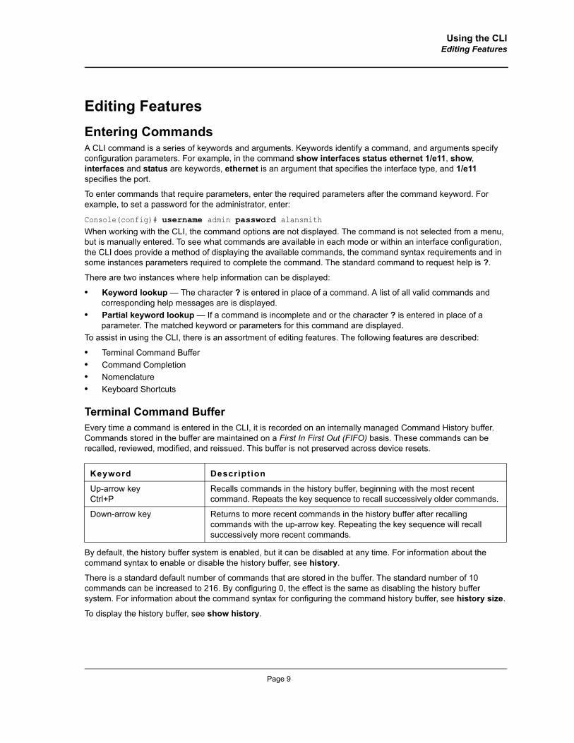
Editing FeaturesEntering CommandsA CLI command is a series of keywords and arguments. Keywords identify a command, and arguments specify configuration parameters. For example, in the command show interfaces status ethernet 1/e11, show, interfaces and status are keywords, ethernet is an argument that specifies the interface type, and 1/e11 specifies the port.
To enter commands that require parameters, enter the required parameters after the command keyword. For example, to set a password for the administrator, enter:
Console(config)# username admin password alansmithWhen working with the CLI, the command options are not displayed. The command is not selected from a menu, but is manually entered. To see what commands are available in each mode or within an interface configuration, the CLI does provide a method of displaying the available commands, the command syntax requirements and in some instances parameters required to complete the command. The standard command to request help is ?.
There are two instances where help information can be displayed:
• Keyword lookup — The character ? is entered in place of a command. A list of all valid commands and corresponding help messages are is displayed.
• Partial keyword lookup — If a command is incomplete and or the character ? is entered in place of a parameter. The matched keyword or parameters for this command are displayed.
To assist in using the CLI, there is an assortment of editing features. The following features are described:
• Terminal Command Buffer• Command Completion• Nomenclature• Keyboard Shortcuts
Terminal Command BufferEvery time a command is entered in the CLI, it is recorded on an internally managed Command History buffer. Commands stored in the buffer are maintained on a First In First Out (FIFO) basis. These commands can be recalled, reviewed, modified, and reissued. This buffer is not preserved across device resets.
By default, the history buffer system is enabled, but it can be disabled at any time. For information about the command syntax to enable or disable the history buffer, see history.
There is a standard default number of commands that are stored in the buffer. The standard number of 10 commands can be increased to 216. By configuring 0, the effect is the same as disabling the history buffer system. For information about the command syntax for configuring the command history buffer, see history size.
To display the history buffer, see show history.
Keyword Description
Up-arrow keyCtrl+P
Recalls commands in the history buffer, beginning with the most recent command. Repeats the key sequence to recall successively older commands.
Down-arrow key Returns to more recent commands in the history buffer after recalling commands with the up-arrow key. Repeating the key sequence will recall successively more recent commands.
Page 9
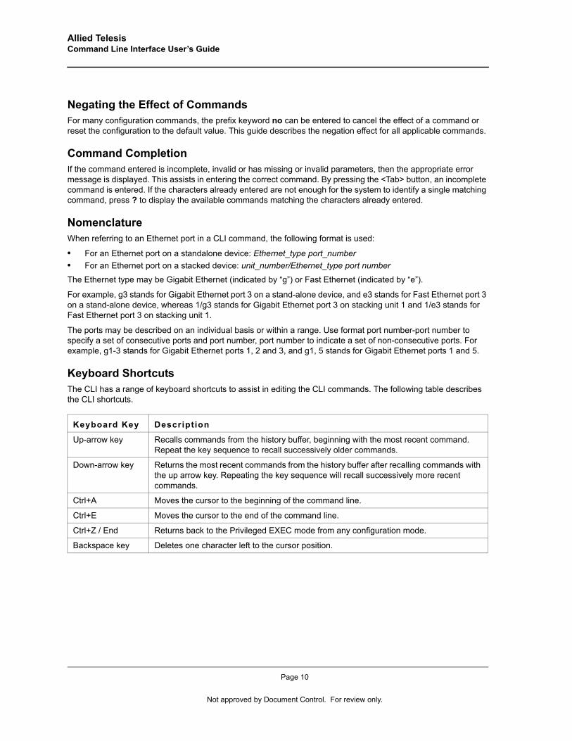
Allied Telesis Command Line Interface User’s Guide
Negating the Effect of CommandsFor many configuration commands, the prefix keyword no can be entered to cancel the effect of a command or reset the configuration to the default value. This guide describes the negation effect for all applicable commands.
Command CompletionIf the command entered is incomplete, invalid or has missing or invalid parameters, then the appropriate error message is displayed. This assists in entering the correct command. By pressing the <Tab> button, an incomplete command is entered. If the characters already entered are not enough for the system to identify a single matching command, press ? to display the available commands matching the characters already entered.
NomenclatureWhen referring to an Ethernet port in a CLI command, the following format is used:
• For an Ethernet port on a standalone device: Ethernet_type port_number• For an Ethernet port on a stacked device: unit_number/Ethernet_type port number
The Ethernet type may be Gigabit Ethernet (indicated by “g”) or Fast Ethernet (indicated by “e”).
For example, g3 stands for Gigabit Ethernet port 3 on a stand-alone device, and e3 stands for Fast Ethernet port 3 on a stand-alone device, whereas 1/g3 stands for Gigabit Ethernet port 3 on stacking unit 1 and 1/e3 stands for Fast Ethernet port 3 on stacking unit 1.
The ports may be described on an individual basis or within a range. Use format port number-port number to specify a set of consecutive ports and port number, port number to indicate a set of non-consecutive ports. For example, g1-3 stands for Gigabit Ethernet ports 1, 2 and 3, and g1, 5 stands for Gigabit Ethernet ports 1 and 5.
Keyboard ShortcutsThe CLI has a range of keyboard shortcuts to assist in editing the CLI commands. The following table describes the CLI shortcuts.
Keyboard Key Description
Up-arrow key Recalls commands from the history buffer, beginning with the most recent command. Repeat the key sequence to recall successively older commands.
Down-arrow key Returns the most recent commands from the history buffer after recalling commands with the up arrow key. Repeating the key sequence will recall successively more recent commands.
Ctrl+A Moves the cursor to the beginning of the command line.
Ctrl+E Moves the cursor to the end of the command line.
Ctrl+Z / End Returns back to the Privileged EXEC mode from any configuration mode.
Backspace key Deletes one character left to the cursor position.
Page 10
Not approved by Document Control. For review only.
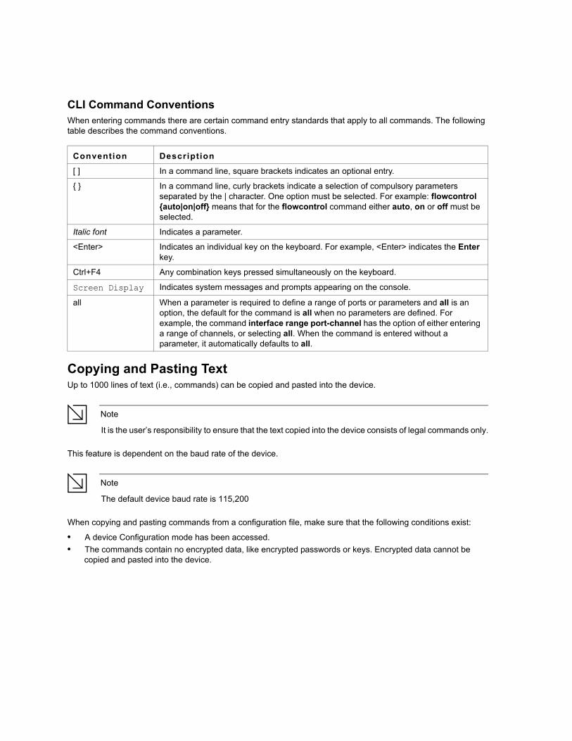
CLI Command ConventionsWhen entering commands there are certain command entry standards that apply to all commands. The following table describes the command conventions.
Copying and Pasting TextUp to 1000 lines of text (i.e., commands) can be copied and pasted into the device.
Note
It is the user’s responsibility to ensure that the text copied into the device consists of legal commands only.
This feature is dependent on the baud rate of the device.
Note
The default device baud rate is 115,200
When copying and pasting commands from a configuration file, make sure that the following conditions exist:
• A device Configuration mode has been accessed.• The commands contain no encrypted data, like encrypted passwords or keys. Encrypted data cannot be
copied and pasted into the device.
Convention Description
[ ] In a command line, square brackets indicates an optional entry.
{ } In a command line, curly brackets indicate a selection of compulsory parameters separated by the | character. One option must be selected. For example: flowcontrol {auto|on|off} means that for the flowcontrol command either auto, on or off must be selected.
Italic font Indicates a parameter.
<Enter> Indicates an individual key on the keyboard. For example, <Enter> indicates the Enter key.
Ctrl+F4 Any combination keys pressed simultaneously on the keyboard.
Screen Display Indicates system messages and prompts appearing on the console.
all When a parameter is required to define a range of ports or parameters and all is an option, the default for the command is all when no parameters are defined. For example, the command interface range port-channel has the option of either entering a range of channels, or selecting all. When the command is entered without a parameter, it automatically defaults to all.

Allied Telesis Command Line Interface User’s Guide
Page 12
Not approved by Document Control. For review only.
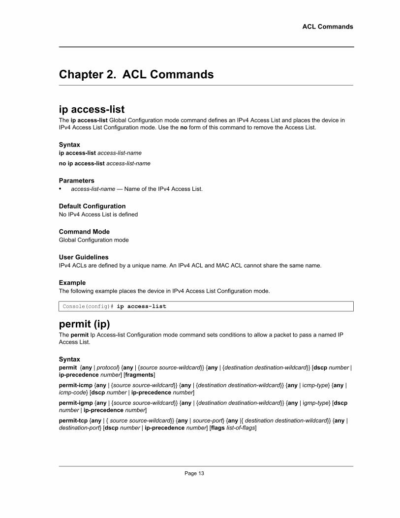
ACL Commands
Chapter 2. ACL Commands
ip access-listThe ip access-list Global Configuration mode command defines an IPv4 Access List and places the device in IPv4 Access List Configuration mode. Use the no form of this command to remove the Access List.
Syntaxip access-list access-list-name
no ip access-list access-list-name
Parameters• access-list-name — Name of the IPv4 Access List.
Default ConfigurationNo IPv4 Access List is defined
Command ModeGlobal Configuration mode
User GuidelinesIPv4 ACLs are defined by a unique name. An IPv4 ACL and MAC ACL cannot share the same name.
ExampleThe following example places the device in IPv4 Access List Configuration mode.
permit (ip)The permit Ip Access-list Configuration mode command sets conditions to allow a packet to pass a named IP Access List.
Syntaxpermit {any | protocol} {any | {source source-wildcard}} {any | {destination destination-wildcard}} [dscp number | ip-precedence number] [fragments]
permit-icmp {any | {source source-wildcard}} {any | {destination destination-wildcard}} {any | icmp-type} {any | icmp-code} [dscp number | ip-precedence number]
permit-igmp {any | {source source-wildcard}} {any | {destination destination-wildcard}} {any | igmp-type} [dscp number | ip-precedence number]
permit-tcp {any | { source source-wildcard}} {any | source-port} {any |{ destination destination-wildcard}} {any | destination-port} [dscp number | ip-precedence number] [flags list-of-flags]
Console(config)# ip access-list
Page 13
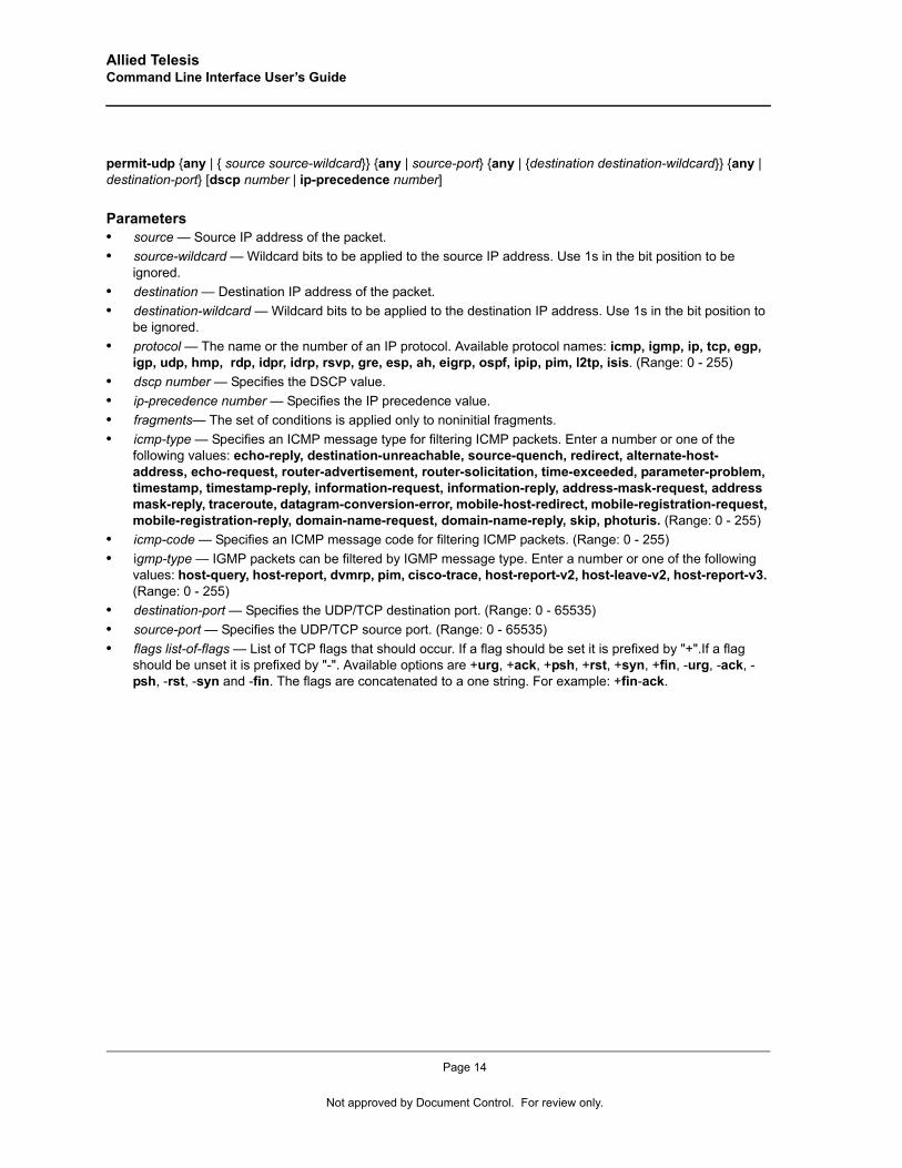
Allied Telesis Command Line Interface User’s Guide
permit-udp {any | { source source-wildcard}} {any | source-port} {any | {destination destination-wildcard}} {any | destination-port} [dscp number | ip-precedence number]
Parameters• source — Source IP address of the packet.• source-wildcard — Wildcard bits to be applied to the source IP address. Use 1s in the bit position to be
ignored.• destination — Destination IP address of the packet.• destination-wildcard — Wildcard bits to be applied to the destination IP address. Use 1s in the bit position to
be ignored.• protocol — The name or the number of an IP protocol. Available protocol names: icmp, igmp, ip, tcp, egp,
igp, udp, hmp, rdp, idpr, idrp, rsvp, gre, esp, ah, eigrp, ospf, ipip, pim, l2tp, isis. (Range: 0 - 255)• dscp number — Specifies the DSCP value.• ip-precedence number — Specifies the IP precedence value.• fragments— The set of conditions is applied only to noninitial fragments.• icmp-type — Specifies an ICMP message type for filtering ICMP packets. Enter a number or one of the
following values: echo-reply, destination-unreachable, source-quench, redirect, alternate-host-address, echo-request, router-advertisement, router-solicitation, time-exceeded, parameter-problem, timestamp, timestamp-reply, information-request, information-reply, address-mask-request, address mask-reply, traceroute, datagram-conversion-error, mobile-host-redirect, mobile-registration-request, mobile-registration-reply, domain-name-request, domain-name-reply, skip, photuris. (Range: 0 - 255)
• icmp-code — Specifies an ICMP message code for filtering ICMP packets. (Range: 0 - 255)• igmp-type — IGMP packets can be filtered by IGMP message type. Enter a number or one of the following
values: host-query, host-report, dvmrp, pim, cisco-trace, host-report-v2, host-leave-v2, host-report-v3. (Range: 0 - 255)
• destination-port — Specifies the UDP/TCP destination port. (Range: 0 - 65535)• source-port — Specifies the UDP/TCP source port. (Range: 0 - 65535)• flags list-of-flags — List of TCP flags that should occur. If a flag should be set it is prefixed by "+".If a flag
should be unset it is prefixed by "-". Available options are +urg, +ack, +psh, +rst, +syn, +fin, -urg, -ack, -psh, -rst, -syn and -fin. The flags are concatenated to a one string. For example: +fin-ack.
Page 14
Not approved by Document Control. For review only.
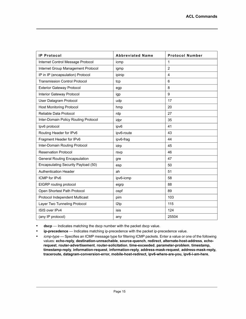
ACL Commands
• dscp — Indicates matching the dscp number with the packet dscp value. • ip-precedence — Indicates matching ip-precedence with the packet ip-precedence value.• icmp-type — Specifies an ICMP message type for filtering ICMP packets. Enter a value or one of the following
values: echo-reply, destination-unreachable, source-quench, redirect, alternate-host-address, echo-request, router-advertisement, router-solicitation, time-exceeded, parameter-problem, timestamp, timestamp-reply, information-request, information-reply, address-mask-request, address-mask-reply, traceroute, datagram-conversion-error, mobile-host-redirect, ipv6-where-are-you, ipv6-i-am-here,
IP Protocol Abbreviated Name Protocol Number
Internet Control Message Protocol icmp 1
Internet Group Management Protocol igmp 2
IP in IP (encapsulation) Protocol ipinip 4
Transmission Control Protocol tcp 6
Exterior Gateway Protocol egp 8
Interior Gateway Protocol igp 9
User Datagram Protocol udp 17
Host Monitoring Protocol hmp 20
Reliable Data Protocol rdp 27
Inter-Domain Policy Routing Protocol idpr 35
Ipv6 protocol ipv6 41
Routing Header for IPv6 ipv6-route 43
Fragment Header for IPv6 ipv6-frag 44
Inter-Domain Routing Protocol idrp 45
Reservation Protocol rsvp 46
General Routing Encapsulation gre 47
Encapsulating Security Payload (50) esp 50
Authentication Header ah 51
ICMP for IPv6 ipv6-icmp 58
EIGRP routing protocol eigrp 88
Open Shortest Path Protocol ospf 89
Protocol Independent Multicast pim 103
Layer Two Tunneling Protocol l2tp 115
ISIS over IPv4 isis 124
(any IP protocol) any 25504
Page 15
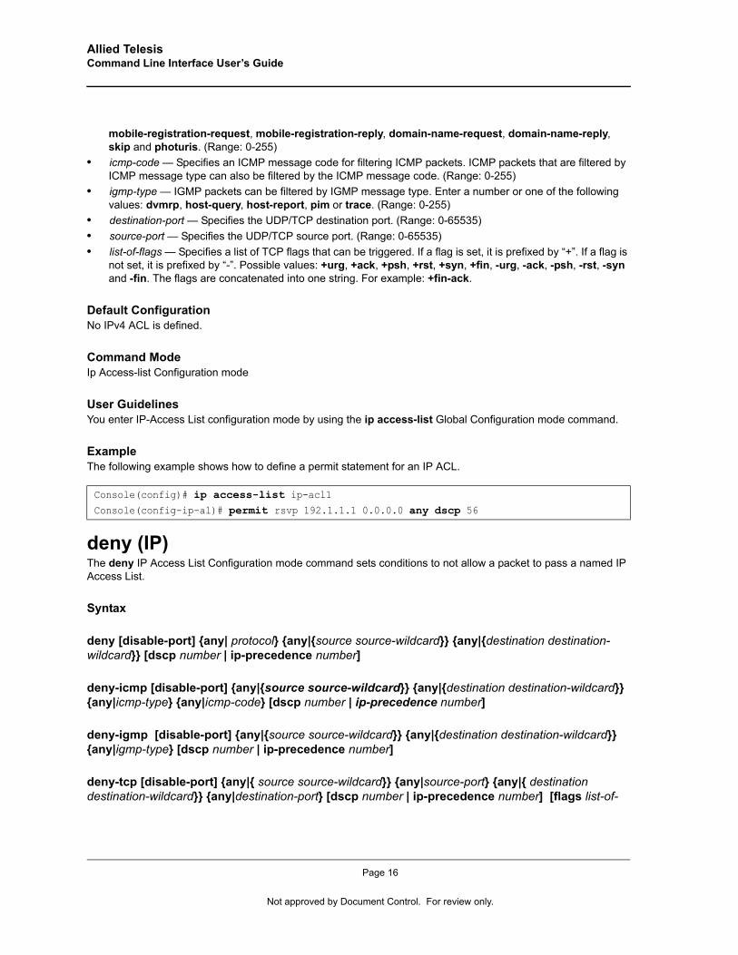
Allied Telesis Command Line Interface User’s Guide
mobile-registration-request, mobile-registration-reply, domain-name-request, domain-name-reply, skip and photuris. (Range: 0-255)
• icmp-code — Specifies an ICMP message code for filtering ICMP packets. ICMP packets that are filtered by ICMP message type can also be filtered by the ICMP message code. (Range: 0-255)
• igmp-type — IGMP packets can be filtered by IGMP message type. Enter a number or one of the following values: dvmrp, host-query, host-report, pim or trace. (Range: 0-255)
• destination-port — Specifies the UDP/TCP destination port. (Range: 0-65535)• source-port — Specifies the UDP/TCP source port. (Range: 0-65535)• list-of-flags — Specifies a list of TCP flags that can be triggered. If a flag is set, it is prefixed by “+”. If a flag is
not set, it is prefixed by “-”. Possible values: +urg, +ack, +psh, +rst, +syn, +fin, -urg, -ack, -psh, -rst, -syn and -fin. The flags are concatenated into one string. For example: +fin-ack.
Default ConfigurationNo IPv4 ACL is defined.
Command ModeIp Access-list Configuration mode
User GuidelinesYou enter IP-Access List configuration mode by using the ip access-list Global Configuration mode command.
ExampleThe following example shows how to define a permit statement for an IP ACL.
deny (IP)The deny IP Access List Configuration mode command sets conditions to not allow a packet to pass a named IP Access List.
Syntax
deny [disable-port] {any| protocol} {any|{source source-wildcard}} {any|{destination destination-wildcard}} [dscp number | ip-precedence number]
deny-icmp [disable-port] {any|{source source-wildcard}} {any|{destination destination-wildcard}} {any|icmp-type} {any|icmp-code} [dscp number | ip-precedence number]
deny-igmp [disable-port] {any|{source source-wildcard}} {any|{destination destination-wildcard}} {any|igmp-type} [dscp number | ip-precedence number]
deny-tcp [disable-port] {any|{ source source-wildcard}} {any|source-port} {any|{ destination destination-wildcard}} {any|destination-port} [dscp number | ip-precedence number] [flags list-of-
Console(config)# ip access-list ip-acl1Console(config-ip-al)# permit rsvp 192.1.1.1 0.0.0.0 any dscp 56
Page 16
Not approved by Document Control. For review only.

ACL Commands
flags]
deny-udp [disable-port] {any|{ source source-wildcard}} {any| source-port} {any|{destination destination-wildcard}} {any|destination-port} [dscp number | ip-precedence number]
Parameters• disable-port — The Ethernet interface is disabled if the condition is matched. (Range: 0 - 65535)• source — Source IP address of the packet.• source-wildcard — Wildcard bits to be applied to the source IP address. Use 1s in the bit position to be
ignored.• destination — Packet’s destination IP address.• destination-wildcard — Wildcard bits to be applied to the destination IP address. Use 1s in the bit position to
be ignored.• protocol —The name or number of an IP protocol. Available protocol names: icmp, igmp, ip, tcp, egp, igp,
udp, hmp, rdp, idpr, idrp, rsvp, gre, esp, ah, eigrp, ospf, ipip, pim, l2tp, isis.: (Range: 0 - 255)• dscp number — Specifies the DSCP value. • ip-precedence number — Specifies the IP precedence value.• icmp-type — Specifies an ICMP message type for filtering ICMP packets. Enter a number, or one of the
following values: echo-reply, destination-unreachable, source-quench, redirect, alternate-host-address, echo-request, router-advertisement, router-solicitation, time-exceeded, parameter-problem, timestamp, timestamp-reply, information-request, information-reply, address-mask-request, address-mask-reply, traceroute, datagram-conversion-error, mobile-host-redirect, mobile-registration-request, mobile-registration-reply, domain-name-request, domain-name-reply, skip, photuriss. (Range: 0 - 255)
• icmp-code — Specifies an ICMP message code for filtering ICMP packets. (Range: 0 - 255)• igmp-type — GMP packets can be filtered by IGMP message type. Enter a number, or one of the following
values: host-query, host-report, dvmrp, pim, cisco-trace, host-report-v2, host-leave-v2, host-report-v3. (Range: 0 - 255)
• destination-port — Specifies the UDP/TCP destination port.• source-port — Specifies the UDP/TCP source port. (Range: 0 - 65535)• flags list-of-flags — List of TCP flags that should occur. If a flag is intended to be set, it is prefixed by ‘+’.If a
flag should be unset it is prefixed by ‘-’. Available options are: +urg, +ack, +psh, +rst, +syn, +fin, -urg, -ack, -psh, -rst, -syn and -fin. The flags are concatenated to a single string. For example: +fin-ack.
IP Protocol Abbreviated Name Protocol Number
Internet Control Message Protocol icmp 1
Internet Group Management Protocol igmp 2
Transmission Control Protocol tcp 6
Exterior Gateway Protocol egp 8
Interior Gateway Protocol igp 9
User Datagram Protocol udp 17
Host Monitoring Protocol hmp 20
Reliable Data Protocol rdp 27
Inter-Domain Policy Routing Protocol idpr 35
Page 17
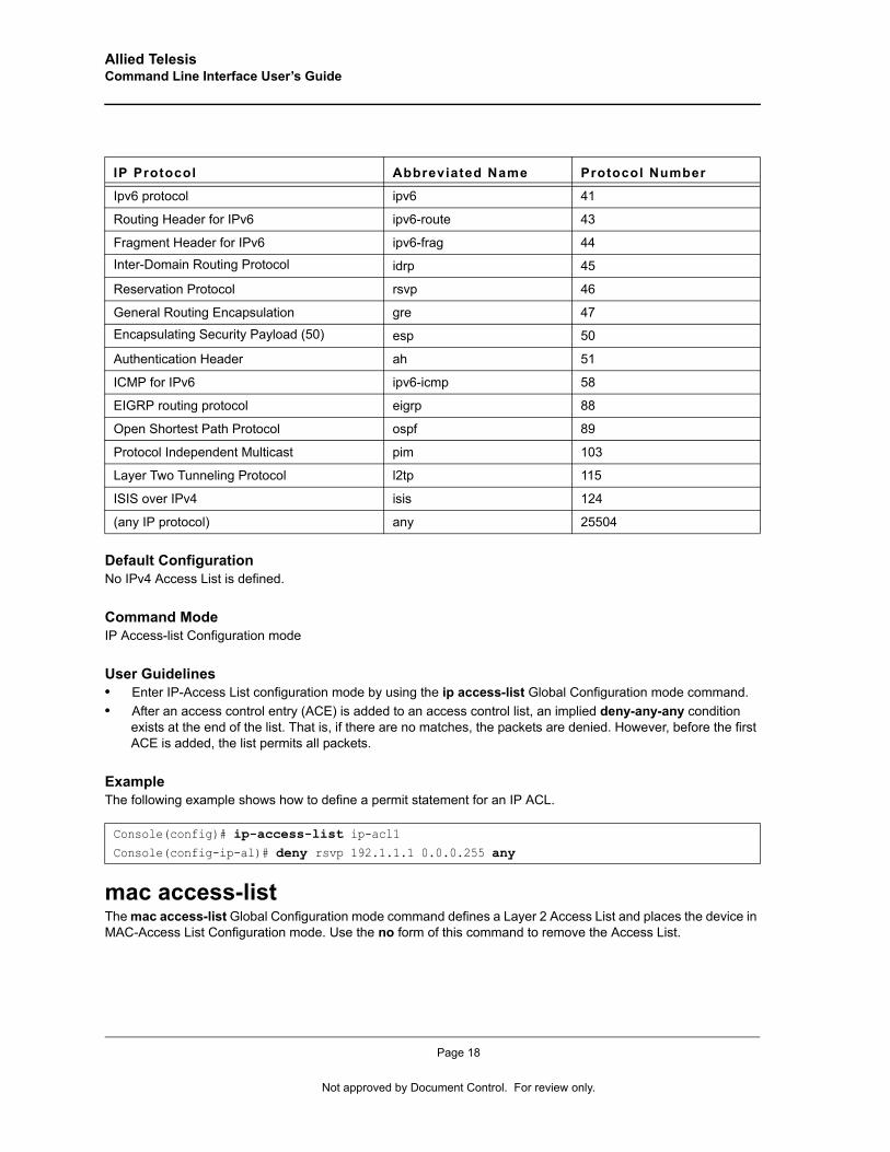
Allied Telesis Command Line Interface User’s Guide
Default ConfigurationNo IPv4 Access List is defined.
Command ModeIP Access-list Configuration mode
User Guidelines• Enter IP-Access List configuration mode by using the ip access-list Global Configuration mode command. • After an access control entry (ACE) is added to an access control list, an implied deny-any-any condition
exists at the end of the list. That is, if there are no matches, the packets are denied. However, before the first ACE is added, the list permits all packets.
ExampleThe following example shows how to define a permit statement for an IP ACL.
mac access-list The mac access-list Global Configuration mode command defines a Layer 2 Access List and places the device in MAC-Access List Configuration mode. Use the no form of this command to remove the Access List.
Ipv6 protocol ipv6 41
Routing Header for IPv6 ipv6-route 43
Fragment Header for IPv6 ipv6-frag 44
Inter-Domain Routing Protocol idrp 45
Reservation Protocol rsvp 46
General Routing Encapsulation gre 47
Encapsulating Security Payload (50) esp 50
Authentication Header ah 51
ICMP for IPv6 ipv6-icmp 58
EIGRP routing protocol eigrp 88
Open Shortest Path Protocol ospf 89
Protocol Independent Multicast pim 103
Layer Two Tunneling Protocol l2tp 115
ISIS over IPv4 isis 124
(any IP protocol) any 25504
Console(config)# ip-access-list ip-acl1Console(config-ip-al)# deny rsvp 192.1.1.1 0.0.0.255 any
IP Protocol Abbreviated Name Protocol Number
Page 18
Not approved by Document Control. For review only.
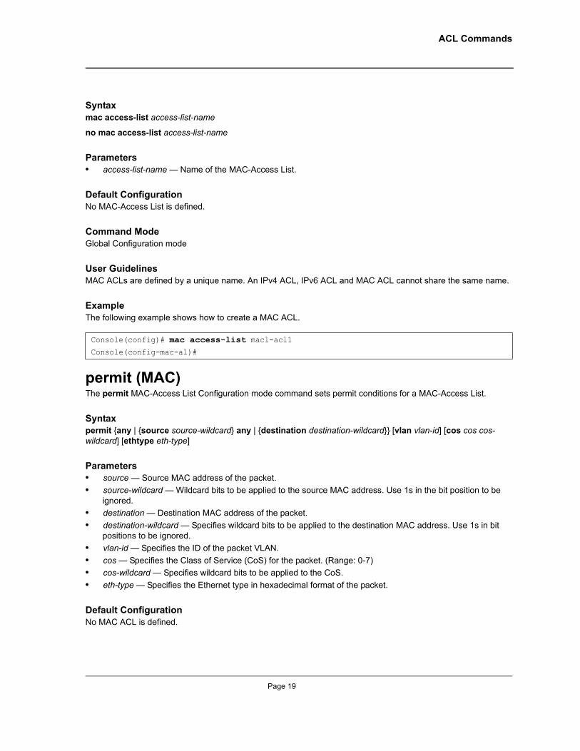
ACL Commands
Syntaxmac access-list access-list-name
no mac access-list access-list-name
Parameters• access-list-name — Name of the MAC-Access List.
Default ConfigurationNo MAC-Access List is defined.
Command ModeGlobal Configuration mode
User GuidelinesMAC ACLs are defined by a unique name. An IPv4 ACL, IPv6 ACL and MAC ACL cannot share the same name.
ExampleThe following example shows how to create a MAC ACL.
permit (MAC)The permit MAC-Access List Configuration mode command sets permit conditions for a MAC-Access List.
Syntaxpermit {any | {source source-wildcard} any | {destination destination-wildcard}} [vlan vlan-id] [cos cos cos-wildcard] [ethtype eth-type]
Parameters• source — Source MAC address of the packet.• source-wildcard — Wildcard bits to be applied to the source MAC address. Use 1s in the bit position to be
ignored.• destination — Destination MAC address of the packet.• destination-wildcard — Specifies wildcard bits to be applied to the destination MAC address. Use 1s in bit
positions to be ignored.• vlan-id — Specifies the ID of the packet VLAN.• cos — Specifies the Class of Service (CoS) for the packet. (Range: 0-7)• cos-wildcard — Specifies wildcard bits to be applied to the CoS. • eth-type — Specifies the Ethernet type in hexadecimal format of the packet.
Default ConfigurationNo MAC ACL is defined.
Console(config)# mac access-list macl-acl1Console(config-mac-al)#
Page 19
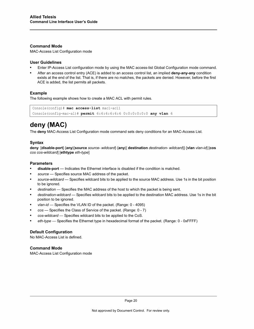
Allied Telesis Command Line Interface User’s Guide
Command ModeMAC-Access List Configuration mode
User Guidelines• Enter IP-Access List configuration mode by using the MAC access-list Global Configuration mode command.• After an access control entry (ACE) is added to an access control list, an implied deny-any-any condition
exists at the end of the list. That is, if there are no matches, the packets are denied. However, before the first ACE is added, the list permits all packets.
ExampleThe following example shows how to create a MAC ACL with permit rules.
deny (MAC)The deny MAC-Access List Configuration mode command sets deny conditions for an MAC-Access List.
Syntaxdeny [disable-port] {any|{source source- wildcard} {any|{ destination destination- wildcard}} [vlan vlan-id] [cos cos cos-wildcard] [ethtype eth-type]
Parameters• disable-port — Indicates the Ethernet interface is disabled if the condition is matched.• source — Specifies source MAC address of the packet.• source-wildcard — Specifies wildcard bits to be applied to the source MAC address. Use 1s in the bit position
to be ignored.• destination — Specifies the MAC address of the host to which the packet is being sent.• destination-wildcard — Specifies wildcard bits to be applied to the destination MAC address. Use 1s in the bit
position to be ignored.• vlan-id — Specifies the VLAN ID of the packet. (Range: 0 - 4095)• cos — Specifies the Class of Service of the packet. (Range: 0 - 7)• cos-wildcard — Specifies wildcard bits to be applied to the CoS.• eth-type — Specifies the Ethernet type in hexadecimal format of the packet. (Range: 0 - 0xFFFF)
Default ConfigurationNo MAC-Access List is defined.
Command ModeMAC-Access List Configuration mode
Console(config)# mac access-list macl-acl1Console(config-mac-al)# permit 6:6:6:6:6:6 0:0:0:0:0:0 any vlan 6
Page 20
Not approved by Document Control. For review only.
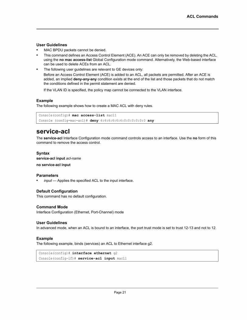
ACL Commands
User Guidelines• MAC BPDU packets cannot be denied.• This command defines an Access Control Element (ACE). An ACE can only be removed by deleting the ACL,
using the no mac access-list Global Configuration mode command. Alternatively, the Web-based interface can be used to delete ACEs from an ACL.
• The following user guidelines are relevant to GE devices only:Before an Access Control Element (ACE) is added to an ACL, all packets are permitted. After an ACE is added, an implied deny-any-any condition exists at the end of the list and those packets that do not match the conditions defined in the permit statement are denied.
If the VLAN ID is specified, the policy map cannot be connected to the VLAN interface.
ExampleThe following example shows how to create a MAC ACL with deny rules.
service-aclThe service-acl Interface Configuration mode command controls access to an interface. Use the no form of this command to remove the access control.
Syntaxservice-acl input acl-name
no service-acl input
Parameters• input — Applies the specified ACL to the input interface.
Default ConfigurationThis command has no default configuration.
Command ModeInterface Configuration (Ethernet, Port-Channel) mode
User GuidelinesIn advanced mode, when an ACL is bound to an interface, the port trust mode is set to trust 12-13 and not to 12.
ExampleThe following example, binds (services) an ACL to Ethernet interface g2.
Console(config)# mac access-list macl1Console (config-mac-acl)# deny 6:6:6:6:6:6:0:0:0:0:0:0 any
Console(config)# interface ethernet g2Console(config-if)# service-acl input macl1
Page 21
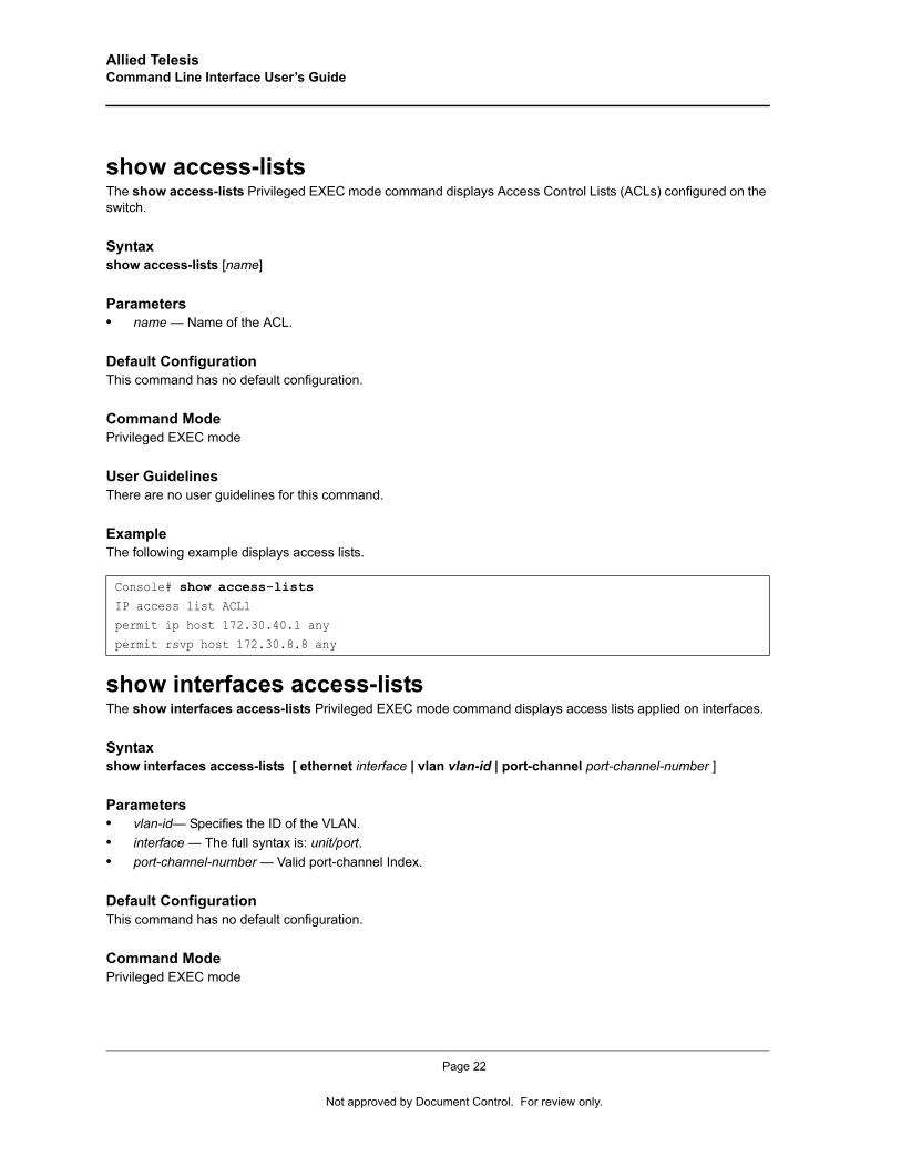
Allied Telesis Command Line Interface User’s Guide
show access-listsThe show access-lists Privileged EXEC mode command displays Access Control Lists (ACLs) configured on the switch.
Syntaxshow access-lists [name]
Parameters• name — Name of the ACL.
Default ConfigurationThis command has no default configuration.
Command ModePrivileged EXEC mode
User GuidelinesThere are no user guidelines for this command.
ExampleThe following example displays access lists.
show interfaces access-listsThe show interfaces access-lists Privileged EXEC mode command displays access lists applied on interfaces.
Syntax show interfaces access-lists [ ethernet interface | vlan vlan-id | port-channel port-channel-number ]
Parameters• vlan-id— Specifies the ID of the VLAN.• interface — The full syntax is: unit/port.• port-channel-number — Valid port-channel Index.
Default ConfigurationThis command has no default configuration.
Command ModePrivileged EXEC mode
Console# show access-listsIP access list ACL1
permit ip host 172.30.40.1 any
permit rsvp host 172.30.8.8 any
Page 22
Not approved by Document Control. For review only.
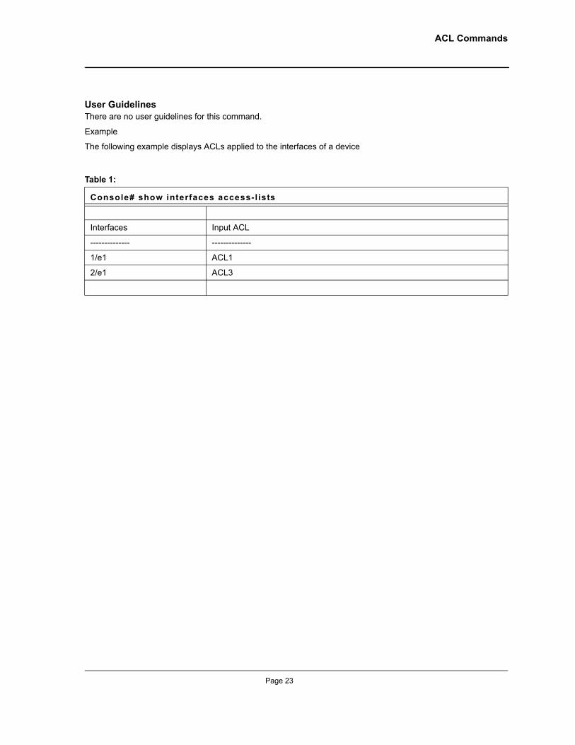
ACL Commands
User GuidelinesThere are no user guidelines for this command.
Example
The following example displays ACLs applied to the interfaces of a device
Table 1:
Console# show interfaces access-l ists
Interfaces Input ACL
-------------- --------------
1/e1 ACL1
2/e1 ACL3
Page 23
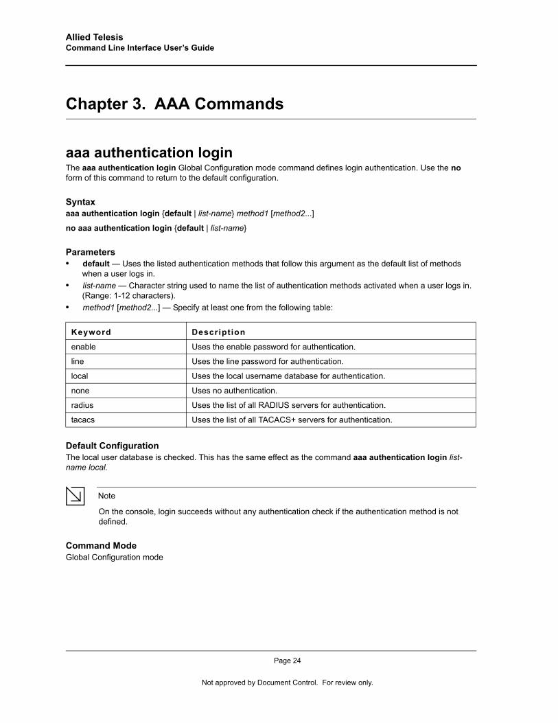
Allied Telesis Command Line Interface User’s Guide
Chapter 3. AAA Commands
aaa authentication loginThe aaa authentication login Global Configuration mode command defines login authentication. Use the no form of this command to return to the default configuration.
Syntaxaaa authentication login {default | list-name} method1 [method2...]
no aaa authentication login {default | list-name}
Parameters• default — Uses the listed authentication methods that follow this argument as the default list of methods
when a user logs in.• list-name — Character string used to name the list of authentication methods activated when a user logs in.
(Range: 1-12 characters).• method1 [method2...] — Specify at least one from the following table:
Default ConfigurationThe local user database is checked. This has the same effect as the command aaa authentication login list-name local.
Note
On the console, login succeeds without any authentication check if the authentication method is not defined.
Command ModeGlobal Configuration mode
Keyword Description
enable Uses the enable password for authentication.
line Uses the line password for authentication.
local Uses the local username database for authentication.
none Uses no authentication.
radius Uses the list of all RADIUS servers for authentication.
tacacs Uses the list of all TACACS+ servers for authentication.
Page 24
Not approved by Document Control. For review only.
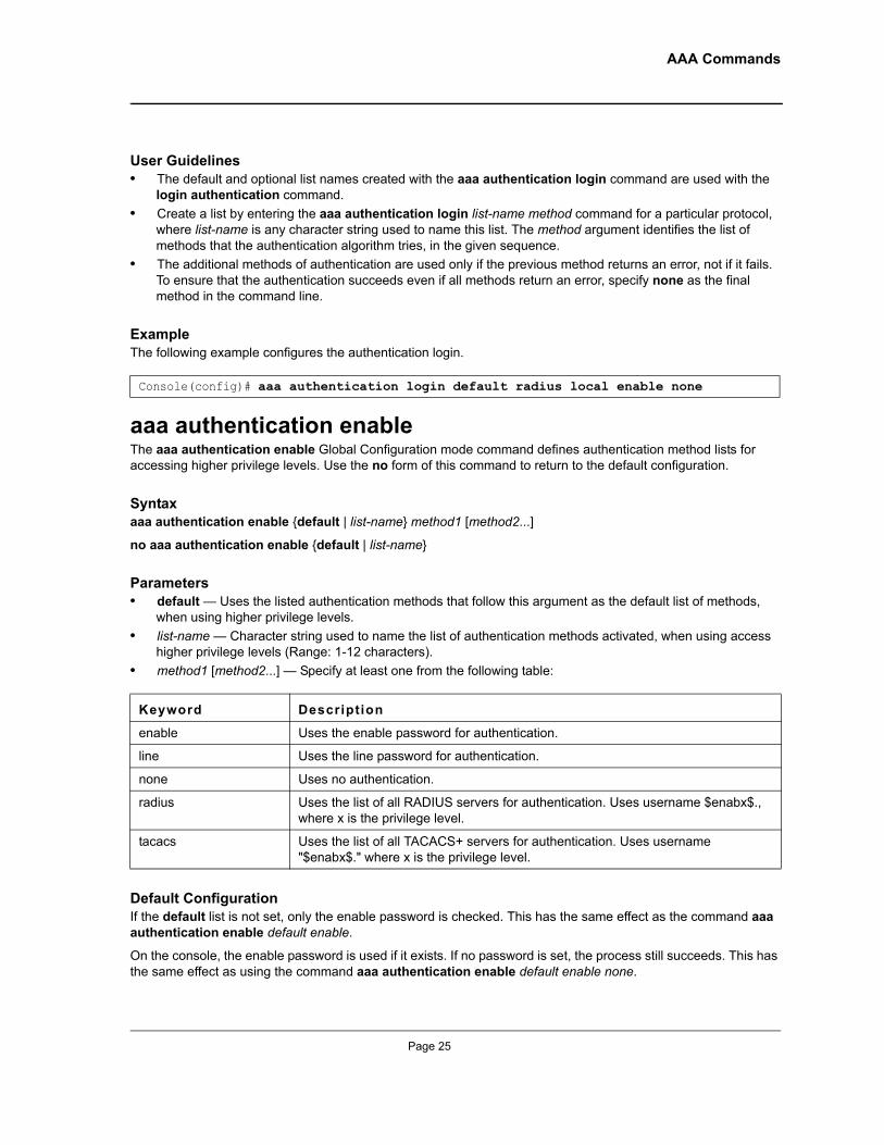
AAA Commands
User Guidelines• The default and optional list names created with the aaa authentication login command are used with the
login authentication command.• Create a list by entering the aaa authentication login list-name method command for a particular protocol,
where list-name is any character string used to name this list. The method argument identifies the list of methods that the authentication algorithm tries, in the given sequence.
• The additional methods of authentication are used only if the previous method returns an error, not if it fails. To ensure that the authentication succeeds even if all methods return an error, specify none as the final method in the command line.
ExampleThe following example configures the authentication login.
aaa authentication enableThe aaa authentication enable Global Configuration mode command defines authentication method lists for accessing higher privilege levels. Use the no form of this command to return to the default configuration.
Syntaxaaa authentication enable {default | list-name} method1 [method2...]
no aaa authentication enable {default | list-name}
Parameters• default — Uses the listed authentication methods that follow this argument as the default list of methods,
when using higher privilege levels.• list-name — Character string used to name the list of authentication methods activated, when using access
higher privilege levels (Range: 1-12 characters).• method1 [method2...] — Specify at least one from the following table:
Default ConfigurationIf the default list is not set, only the enable password is checked. This has the same effect as the command aaa authentication enable default enable.
On the console, the enable password is used if it exists. If no password is set, the process still succeeds. This has the same effect as using the command aaa authentication enable default enable none.
Console(config)# aaa authentication login default radius local enable none
Keyword Description
enable Uses the enable password for authentication.
line Uses the line password for authentication.
none Uses no authentication.
radius Uses the list of all RADIUS servers for authentication. Uses username $enabx$., where x is the privilege level.
tacacs Uses the list of all TACACS+ servers for authentication. Uses username "$enabx$." where x is the privilege level.
Page 25
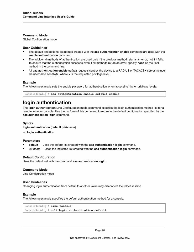
Allied Telesis Command Line Interface User’s Guide
Command ModeGlobal Configuration mode
User Guidelines• The default and optional list names created with the aaa authentication enable command are used with the
enable authentication command.• The additional methods of authentication are used only if the previous method returns an error, not if it fails.
To ensure that the authentication succeeds even if all methods return an error, specify none as the final method in the command line.
• All aaa authentication enable default requests sent by the device to a RADIUS or TACACS+ server include the username $enabx$., where x is the requested privilege level.
ExampleThe following example sets the enable password for authentication when accessing higher privilege levels.
login authenticationThe login authentication Line Configuration mode command specifies the login authentication method list for a remote telnet or console. Use the no form of this command to return to the default configuration specified by the aaa authentication login command.
Syntaxlogin authentication {default | list-name}
no login authentication
Parameters• default — Uses the default list created with the aaa authentication login command.• list-name — Uses the indicated list created with the aaa authentication login command.
Default ConfigurationUses the default set with the command aaa authentication login.
Command ModeLine Configuration mode
User GuidelinesChanging login authentication from default to another value may disconnect the telnet session.
ExampleThe following example specifies the default authentication method for a console.
Console(config)# aaa authentication enable default enable
Console(config)# line consoleConsole(config-line)# login authentication default
Page 26
Not approved by Document Control. For review only.
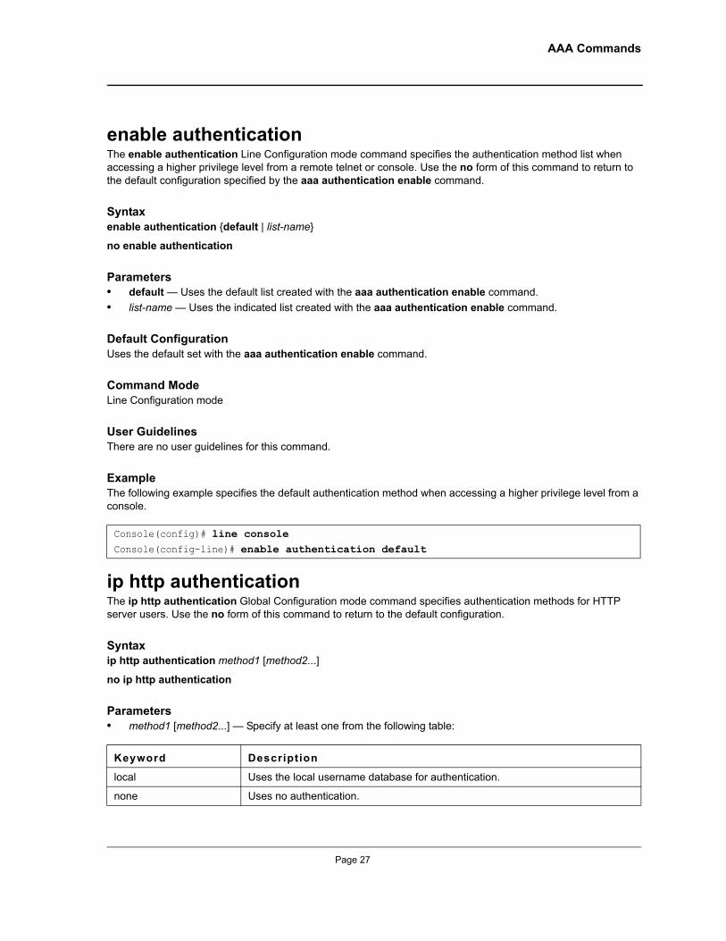
AAA Commands
enable authenticationThe enable authentication Line Configuration mode command specifies the authentication method list when accessing a higher privilege level from a remote telnet or console. Use the no form of this command to return to the default configuration specified by the aaa authentication enable command.
Syntaxenable authentication {default | list-name}
no enable authentication
Parameters• default — Uses the default list created with the aaa authentication enable command.• list-name — Uses the indicated list created with the aaa authentication enable command.
Default ConfigurationUses the default set with the aaa authentication enable command.
Command ModeLine Configuration mode
User GuidelinesThere are no user guidelines for this command.
ExampleThe following example specifies the default authentication method when accessing a higher privilege level from a console.
ip http authenticationThe ip http authentication Global Configuration mode command specifies authentication methods for HTTP server users. Use the no form of this command to return to the default configuration.
Syntaxip http authentication method1 [method2...]
no ip http authentication
Parameters• method1 [method2...] — Specify at least one from the following table:
Console(config)# line consoleConsole(config-line)# enable authentication default
Keyword Description
local Uses the local username database for authentication.
none Uses no authentication.
Page 27
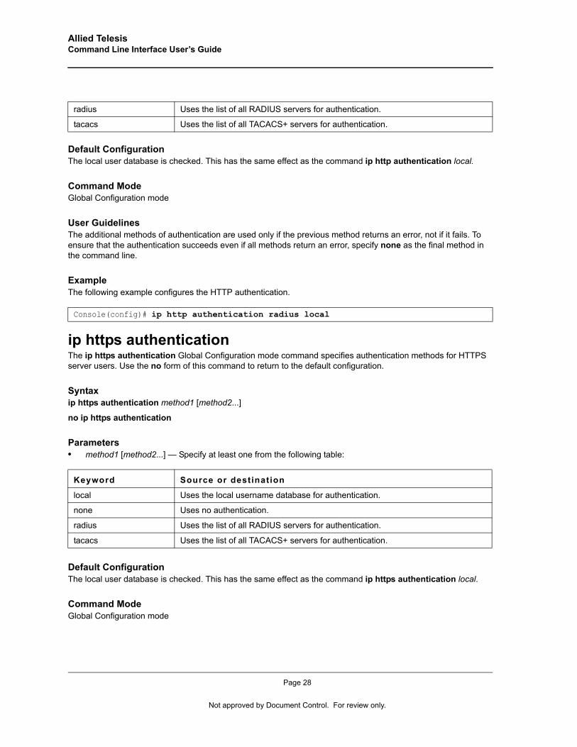
Allied Telesis Command Line Interface User’s Guide
Default ConfigurationThe local user database is checked. This has the same effect as the command ip http authentication local.
Command ModeGlobal Configuration mode
User GuidelinesThe additional methods of authentication are used only if the previous method returns an error, not if it fails. To ensure that the authentication succeeds even if all methods return an error, specify none as the final method in the command line.
ExampleThe following example configures the HTTP authentication.
ip https authenticationThe ip https authentication Global Configuration mode command specifies authentication methods for HTTPS server users. Use the no form of this command to return to the default configuration.
Syntaxip https authentication method1 [method2...]
no ip https authentication
Parameters• method1 [method2...] — Specify at least one from the following table:
Default ConfigurationThe local user database is checked. This has the same effect as the command ip https authentication local.
Command ModeGlobal Configuration mode
radius Uses the list of all RADIUS servers for authentication.
tacacs Uses the list of all TACACS+ servers for authentication.
Console(config)# ip http authentication radius local
Keyword Source or destination
local Uses the local username database for authentication.
none Uses no authentication.
radius Uses the list of all RADIUS servers for authentication.
tacacs Uses the list of all TACACS+ servers for authentication.
Page 28
Not approved by Document Control. For review only.
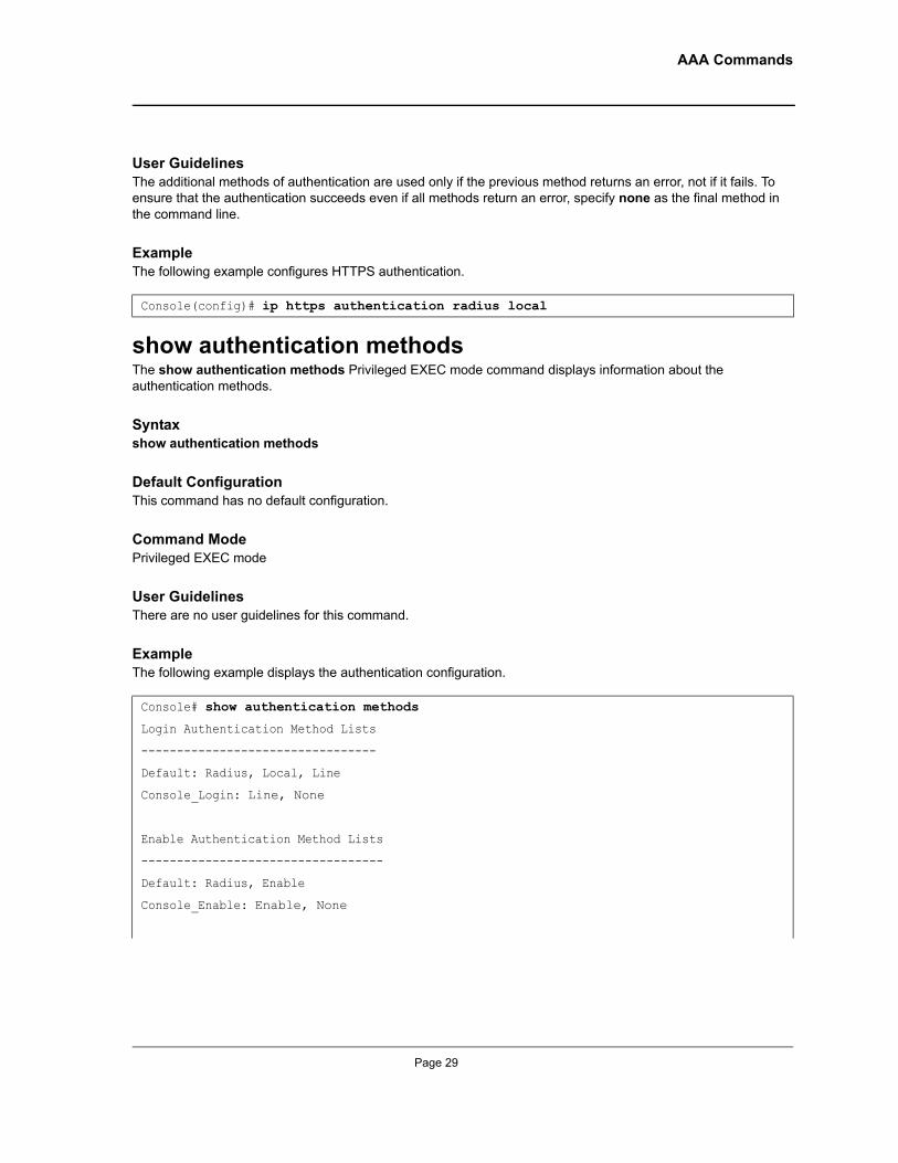
AAA Commands
User GuidelinesThe additional methods of authentication are used only if the previous method returns an error, not if it fails. To ensure that the authentication succeeds even if all methods return an error, specify none as the final method in the command line.
ExampleThe following example configures HTTPS authentication.
show authentication methodsThe show authentication methods Privileged EXEC mode command displays information about the authentication methods.
Syntaxshow authentication methods
Default ConfigurationThis command has no default configuration.
Command ModePrivileged EXEC mode
User GuidelinesThere are no user guidelines for this command.
ExampleThe following example displays the authentication configuration.
Console(config)# ip https authentication radius local
Console# show authentication methods
Login Authentication Method Lists
---------------------------------
Default: Radius, Local, Line
Console_Login: Line, None
Enable Authentication Method Lists
----------------------------------
Default: Radius, Enable
Console_Enable: Enable, None
Page 29
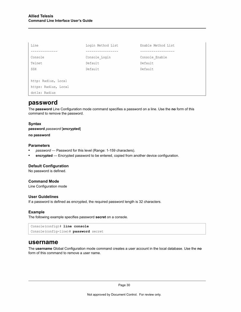
Allied Telesis Command Line Interface User’s Guide
passwordThe password Line Configuration mode command specifies a password on a line. Use the no form of this command to remove the password.
Syntaxpassword password [encrypted]
no password
Parameters• password — Password for this level (Range: 1-159 characters).• encrypted — Encrypted password to be entered, copied from another device configuration.
Default ConfigurationNo password is defined.
Command ModeLine Configuration mode
User GuidelinesIf a password is defined as encrypted, the required password length is 32 characters.
ExampleThe following example specifies password secret on a console.
usernameThe username Global Configuration mode command creates a user account in the local database. Use the no form of this command to remove a user name.
Line Login Method List Enable Method List
-------------- ----------------- ------------------
Console Console_Login Console_Enable
Telnet Default Default
SSH Default Default
http: Radius, Local
https: Radius, Local
dot1x: Radius
Console(config)# line consoleConsole(config-line)# password secret
Page 30
Not approved by Document Control. For review only.
AAA Commands
Syntaxusername name [password password] [level level] [encrypted]
no username name
Parameters• name — The name of the user (Range: 1- 20 characters).• password — The authentication password for the user (Range: 1-159 characters).• level — The user level (Range: 1-15).• encrypted — Encrypted password entered, copied from another device configuration.
Default ConfigurationNo user is defined.
Command ModeGlobal Configuration mode
User Guidelines• User account can be created without a password. • A single username can be defined for privilege level 1 and another one for privilege level 15.• Default usernames:
Privilege level 1: username = operator, password = operator
Privilege level 15: username = manager, password = friend
ExampleThe following example configures user bob with password lee and user level 15 to the system.
show users accountsThe show users accounts Privileged EXEC mode command displays information about the local user database.
Syntaxshow users accounts
Default ConfigurationThis command has no default configuration.
Command ModePrivileged EXEC mode
User GuidelinesThere are no user guidelines for this command.
Console(config)# username bob password lee level 15
Page 31
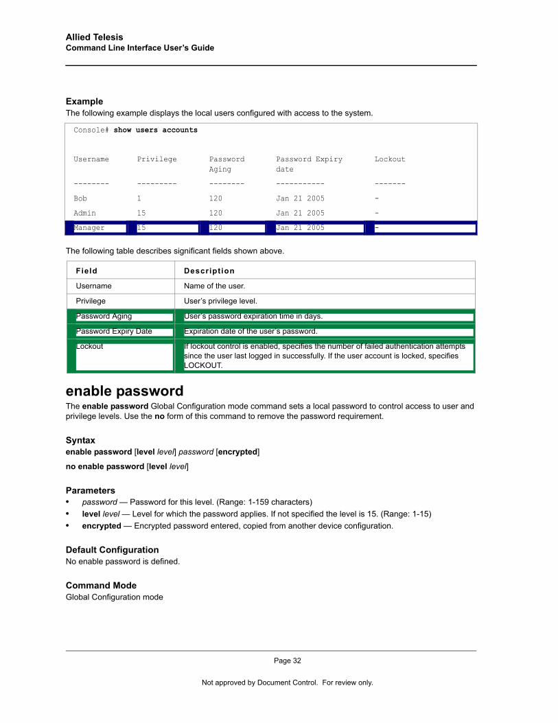
Allied Telesis Command Line Interface User’s Guide
ExampleThe following example displays the local users configured with access to the system.
The following table describes significant fields shown above.
enable password The enable password Global Configuration mode command sets a local password to control access to user and privilege levels. Use the no form of this command to remove the password requirement.
Syntaxenable password [level level] password [encrypted]
no enable password [level level]
Parameters• password — Password for this level. (Range: 1-159 characters)• level level — Level for which the password applies. If not specified the level is 15. (Range: 1-15)• encrypted — Encrypted password entered, copied from another device configuration.
Default ConfigurationNo enable password is defined.
Command ModeGlobal Configuration mode
Console# show users accounts
Username Privilege Password Aging
Password Expiry date
Lockout
-------- --------- -------- ----------- -------
Bob 1 120 Jan 21 2005 -
Admin 15 120 Jan 21 2005 -
Manager 15 120 Jan 21 2005 -
Field Description
Username Name of the user.
Privilege User’s privilege level.
Password Aging User’s password expiration time in days.
Password Expiry Date Expiration date of the user’s password.
Lockout If lockout control is enabled, specifies the number of failed authentication attempts since the user last logged in successfully. If the user account is locked, specifies LOCKOUT.
Page 32
Not approved by Document Control. For review only.
AAA Commands
User GuidelinesThere are no user guidelines for this command.
ExampleThe following example sets a local level 15 password called ‘secret’ to control access to user and privilege levels. .
Console(config)# enable password secret level 15
Page 33
Allied Telesis Command Line Interface User’s Guide
Chapter 4. Address Table Commands
bridge addressThe bridge address Interface Configuration (VLAN) mode command adds a MAC-layer station source address to the bridge table. Use the no form of this command to delete the MAC address.
Syntaxbridge address mac-address {ethernet interface | port-channel port-channel-number} [permanent permanent} | delete-on-reset delete-on-reset} | delete-on-timeout delete-on-timeout} | secure secure]
no bridge address [mac-address]
Parameters• mac-address — A valid MAC address.• interface — A valid Ethernet port.• port-channel-number — A valid port-channel number.• permanent — The address can only be deleted by the no bridge address command.• delete-on-reset — The address is deleted after reset.• delete-on-timeout — The address is deleted after "age out" time has expired.• secure — The address is deleted after the port changes mode to unlock learning (no port security
command). This parameter is only available when the port is in the learning locked mode.
Default Configuration No static addresses are defined. The default mode for an added address is permanent.
Command ModeInterface Configuration (VLAN) mode
User GuidelinesUsing the no form of the command without specifying a MAC address deletes all static MAC addresses belonging to this VLAN).
ExampleThe following example adds a permanent static MAC-layer station source address 3aa2.64b3.a245 on port 1/e16 to the bridge table.
bridge multicast filteringThe bridge multicast filtering Global Configuration mode command enables filtering of Multicast addresses. Use the no form of this command to disable filtering of Multicast addresses.
Console(config)# interface vlan 2Console(config-if)# bridge address 3aa2.64b3.a245 ethernet 1/e16 permanent
Page 34
Not approved by Document Control. For review only.
Address Table Commands
Syntaxbridge multicast filtering
no bridge multicast filtering
ParametersThis command has no keywords or arguments.
Default ConfigurationFiltering Multicast addresses is disabled. All Multicast addresses are flooded to all ports.
Command ModeGlobal Configuration mode
User Guidelines• If routers exist on the VLAN, do not change the unregistered Multicast addresses state to drop on the routers
ports.• If Multicast routers exist on the VLAN and IGMP snooping isn't enabled, use the bridge multicast forward-
all command to enable forwarding all Multicast packets to the Multicast routers.
ExampleIn this example, bridge Multicast filtering is enabled.
bridge multicast addressThe bridge multicast address Interface Configuration mode command registers MAC-layer Multicast addresses to the bridge table, and adds ports statically to the group. Use the no form of this command to deregister the address.
Syntaxbridge multicast address mac-multicast-address
Parameters• add — Adds ports to the group. If no option is specified, this is the default option.• remove — Removes ports from the group.• mac-multicast-address — A valid MAC Multicast address.• interface-list — Separate nonconsecutive Ethernet ports with a comma and no spaces; a hyphen is used to
designate a range of ports.• port-channel-number-list — Separate nonconsecutive port-channels with a comma and no spaces; a hyphen
is used to designate a range of ports.
Default ConfigurationNo Multicast addresses are defined.
Console(config)# bridge multicast filtering
Page 35
Allied Telesis Command Line Interface User’s Guide
Command ModeInterface configuration (VLAN) mode
User Guidelines• If the command is executed without add or remove, the command only registers the group in the bridge
database.• Static Multicast addresses can only be defined on static VLANs.
ExampleThe following example registers the MAC address:
The following example registers the MAC address and adds ports statically.
bridge multicast forbidden addressThe bridge multicast forbidden address Interface Configuration mode command forbids adding specific Multicast addresses to specific ports. Use the no form of this command to return to default.
Syntaxbridge multicast forbidden address {mac-multicast-address | ip-multicast-address} {add | remove} {ethernet interface-list | port-channel port-channel-number-list}
no bridge multicast forbidden address {mac-multicast-address | ip-multicast-address}
Parameters• add — Adds ports to the group.• remove — Removes ports from the group.• mac-multicast-address — A valid MAC Multicast address.• interface-list — Separate nonconsecutive Ethernet ports with a comma and no spaces; hyphen is used to
designate a range of ports.• port-channel-number-list — Separate nonconsecutive valid port-channels with a comma and no spaces; a
hyphen is used to designate a range of port-channels.
Default ConfigurationNo forbidden addresses are defined.
Command ModesInterface Configuration (VLAN) mode
Console(config)# interface vlan 8Console(config-if)# bridge multicast address 01:00:5e:02:02:03
console(config)# interface vlan 8console(config-if)# bridge multicast address 01:00:5e:02:02:03 add ethernet 1/e1-9, 2/e2
Page 36
Not approved by Document Control. For review only.
Address Table Commands
User GuidelinesBefore defining forbidden ports, the Multicast group should be registered.
ExampleIn this example, MAC address 0100.5e02.0203 is forbidden on port 2/e9 within VLAN 8.
bridge multicast forward-allThe bridge multicast forward-all Interface Configuration (VLAN) mode command enables forwarding all Multicast packets on a port. Use the no form of this command to restore the default configuration.
Syntaxbridge multicast forward-all {add | remove} {ethernet interface-list | port-channel port-channel-number-list}
no bridge multicast forward-all
Parameters• add — Force forwarding all Multicast packets.• remove — Do not force forwarding all Multicast packets.• interface-list — Separate nonconsecutive Ethernet ports with a comma and no spaces; a hyphen is used to
designate a range of ports.• port-channel-number-list — Separate nonconsecutive port-channels with a comma and no spaces; a hyphen
is used to designate a range of port-channels.
Default ConfigurationThis setting is disabled.
Command ModeInterface Configuration (VLAN) mode
User GuidelinesThere are no user guidelines for this command.
ExampleIn this example, all Multicast packets on port 1/e8 are forwarded.
Console(config)# interface vlan 8Console(config-if)# bridge multicast address 0100.5e02.0203Console(config-if)# bridge multicast forbidden address 0100.5e02.0203 add ethernet 2/e9
Console(config)# interface vlan 2Console(config-if)# bridge multicast forward-all addethernet 1/e8
Page 37
Allied Telesis Command Line Interface User’s Guide
bridge multicast forbidden forward-allThe bridge multicast forbidden forward-all Interface Configuration mode command forbids a port to be a Forward-all-Multicast port. Use the no form of this command to return to default.
Syntax bridge multicast forbidden forward-all {add | remove} {ethernet interface-list | port-channel port-channel-number-list}
no bridge multicast forbidden forward-all
Parameters• add — Forbid forwarding all Multicast packets.• remove — Do not forbid forwarding all Multicast packets.• interface-list — Separates nonconsecutive Ethernet ports with a comma and no spaces; use a hyphen to
designate a range of ports.• port-channel-number-list — Separates nonconsecutive port-channels with a comma and no spaces; use a
hyphen to designate a range of port-channels.
Default ConfigurationThis setting is disabled.
Command ModeInterface Configuration (VLAN) mode
User Guidelines• IGMP snooping dynamically discovers Multicast router ports. When a Multicast router port is discovered, all
the Multicast packets are forwarded to it unconditionally.• This command prevents a port from becoming a Multicast router port.
ExampleIn this example, forwarding all Multicast packets to 1/e1 with VLAN 2 is forbidden.
bridge aging-timeThe bridge aging-time Global Configuration mode command sets the aging time of the Address Table. Use the no form of this command to restore the default.
Syntaxbridge aging-time seconds
no bridge aging-time
Parameters• seconds — Time in seconds. (Range: 10-630 seconds)
Console(config)# interface vlan 2Console(config-if)# bridge multicast forbidden forward-all add ethernet 1/e1
Page 38
Not approved by Document Control. For review only.
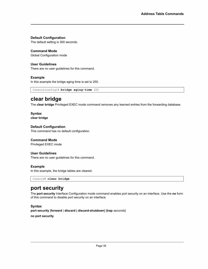
Address Table Commands
Default ConfigurationThe default setting is 300 seconds.
Command ModeGlobal Configuration mode
User GuidelinesThere are no user guidelines for this command.
ExampleIn this example the bridge aging time is set to 250.
clear bridgeThe clear bridge Privileged EXEC mode command removes any learned entries from the forwarding database.
Syntaxclear bridge
Default ConfigurationThis command has no default configuration.
Command ModePrivileged EXEC mode
User GuidelinesThere are no user guidelines for this command.
ExampleIn this example, the bridge tables are cleared.
port securityThe port security Interface Configuration mode command enables port security on an interface. Use the no form of this command to disable port security on an interface.
Syntaxport security [forward | discard | discard-shutdown] [trap seconds]
no port security
Console(config)# bridge aging-time 250
Console# clear bridge
Page 39
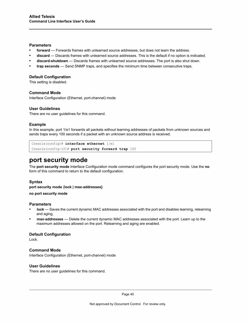
Allied Telesis Command Line Interface User’s Guide
Parameters• forward — Forwards frames with unlearned source addresses, but does not learn the address.• discard — Discards frames with unlearned source addresses. This is the default if no option is indicated.• discard-shutdown — Discards frames with unlearned source addresses. The port is also shut down.• trap seconds — Send SNMP traps, and specifies the minimum time between consecutive traps.
Default Configuration This setting is disabled.
Command ModeInterface Configuration (Ethernet, port-channel) mode
User GuidelinesThere are no user guidelines for this command.
ExampleIn this example, port 1/e1 forwards all packets without learning addresses of packets from unknown sources and sends traps every 100 seconds if a packet with an unknown source address is received.
port security modeThe port security mode Interface Configuration mode command configures the port security mode. Use the no form of this command to return to the default configuration.
Syntaxport security mode {lock | max-addresses}
no port security mode
Parameters• lock — Saves the current dynamic MAC addresses associated with the port and disables learning, relearning
and aging.• max-addresses — Delete the current dynamic MAC addresses associated with the port. Learn up to the
maximum addresses allowed on the port. Relearning and aging are enabled.
Default Configuration Lock.
Command ModeInterface Configuration (Ethernet, port-channel) mode
User GuidelinesThere are no user guidelines for this command.
Console(config)# interface ethernet 1/e1Console(config-if)# port security forward trap 100
Page 40
Not approved by Document Control. For review only.
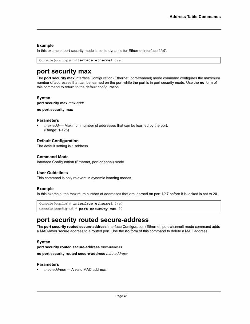
Address Table Commands
ExampleIn this example, port security mode is set to dynamic for Ethernet interface 1/e7.
port security maxThe port security max Interface Configuration (Ethernet, port-channel) mode command configures the maximum number of addresses that can be learned on the port while the port is in port security mode. Use the no form of this command to return to the default configuration.
Syntaxport security max max-addr
no port security max
Parameters• max-addr— Maximum number of addresses that can be learned by the port.
(Range: 1-128)
Default Configuration The default setting is 1 address.
Command ModeInterface Configuration (Ethernet, port-channel) mode
User GuidelinesThis command is only relevant in dynamic learning modes.
ExampleIn this example, the maximum number of addresses that are learned on port 1/e7 before it is locked is set to 20.
port security routed secure-addressThe port security routed secure-address Interface Configuration (Ethernet, port-channel) mode command adds a MAC-layer secure address to a routed port. Use the no form of this command to delete a MAC address.
Syntaxport security routed secure-address mac-address
no port security routed secure-address mac-address
Parameters• mac-address — A valid MAC address.
Console(config)# interface ethernet 1/e7
Console(config)# interface ethernet 1/e7Console(config-if)# port security max 20
Page 41
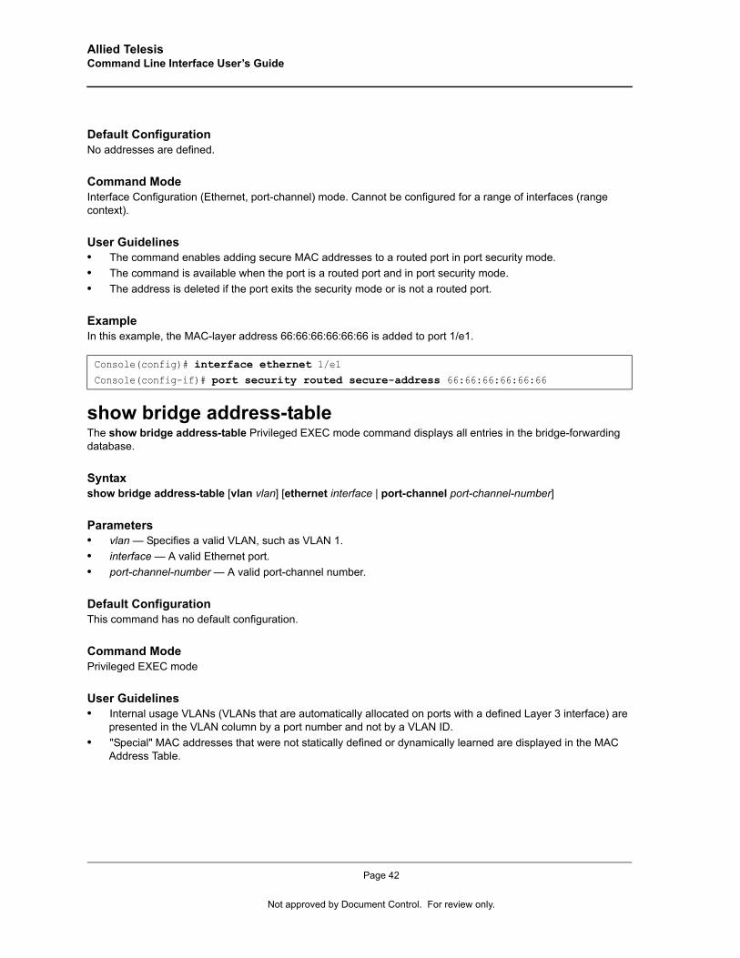
Allied Telesis Command Line Interface User’s Guide
Default Configuration No addresses are defined.
Command ModeInterface Configuration (Ethernet, port-channel) mode. Cannot be configured for a range of interfaces (range context).
User Guidelines• The command enables adding secure MAC addresses to a routed port in port security mode. • The command is available when the port is a routed port and in port security mode. • The address is deleted if the port exits the security mode or is not a routed port.
ExampleIn this example, the MAC-layer address 66:66:66:66:66:66 is added to port 1/e1.
show bridge address-tableThe show bridge address-table Privileged EXEC mode command displays all entries in the bridge-forwarding database.
Syntaxshow bridge address-table [vlan vlan] [ethernet interface | port-channel port-channel-number]
Parameters• vlan — Specifies a valid VLAN, such as VLAN 1.• interface — A valid Ethernet port.• port-channel-number — A valid port-channel number.
Default Configuration This command has no default configuration.
Command ModePrivileged EXEC mode
User Guidelines• Internal usage VLANs (VLANs that are automatically allocated on ports with a defined Layer 3 interface) are
presented in the VLAN column by a port number and not by a VLAN ID. • "Special" MAC addresses that were not statically defined or dynamically learned are displayed in the MAC
Address Table.
Console(config)# interface ethernet 1/e1Console(config-if)# port security routed secure-address 66:66:66:66:66:66
Page 42
Not approved by Document Control. For review only.
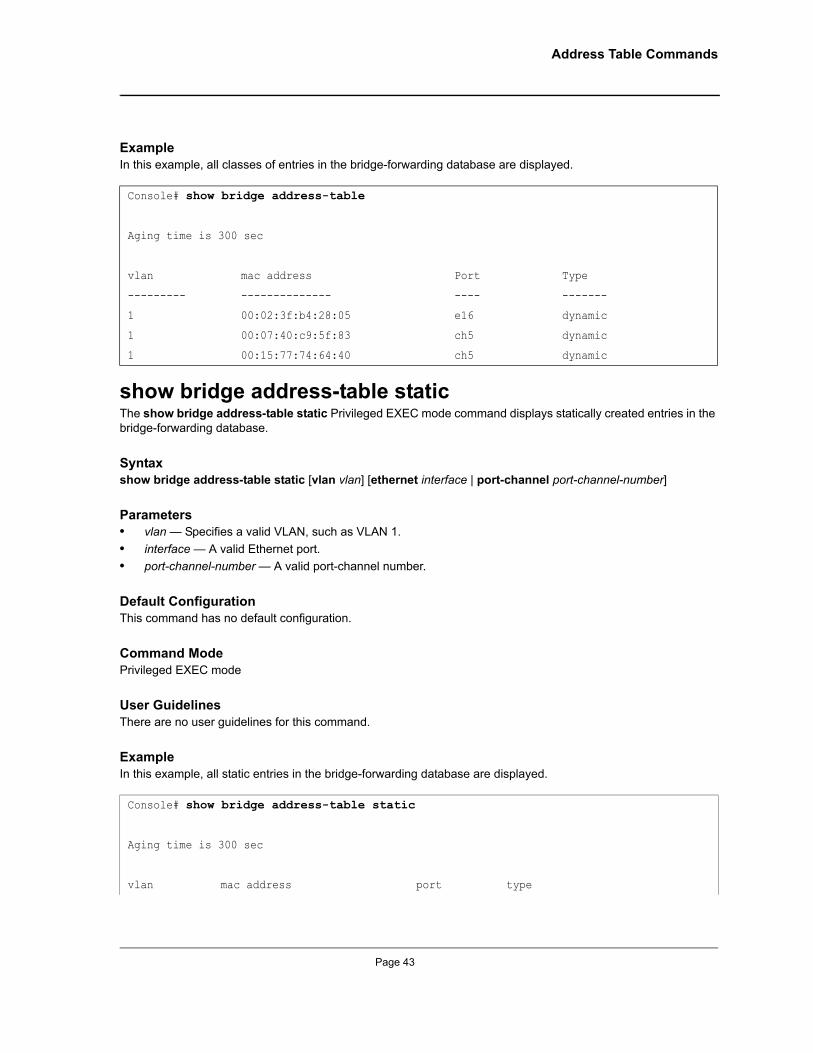
Address Table Commands
ExampleIn this example, all classes of entries in the bridge-forwarding database are displayed.
show bridge address-table staticThe show bridge address-table static Privileged EXEC mode command displays statically created entries in the bridge-forwarding database.
Syntaxshow bridge address-table static [vlan vlan] [ethernet interface | port-channel port-channel-number]
Parameters• vlan — Specifies a valid VLAN, such as VLAN 1.• interface — A valid Ethernet port.• port-channel-number — A valid port-channel number.
Default Configuration This command has no default configuration.
Command ModePrivileged EXEC mode
User GuidelinesThere are no user guidelines for this command.
ExampleIn this example, all static entries in the bridge-forwarding database are displayed.
Console# show bridge address-table
Aging time is 300 sec
vlan mac address Port Type
--------- -------------- ---- -------
1 00:02:3f:b4:28:05 e16 dynamic
1 00:07:40:c9:5f:83 ch5 dynamic
1 00:15:77:74:64:40 ch5 dynamic
Console# show bridge address-table static
Aging time is 300 sec
vlan mac address port type
Page 43
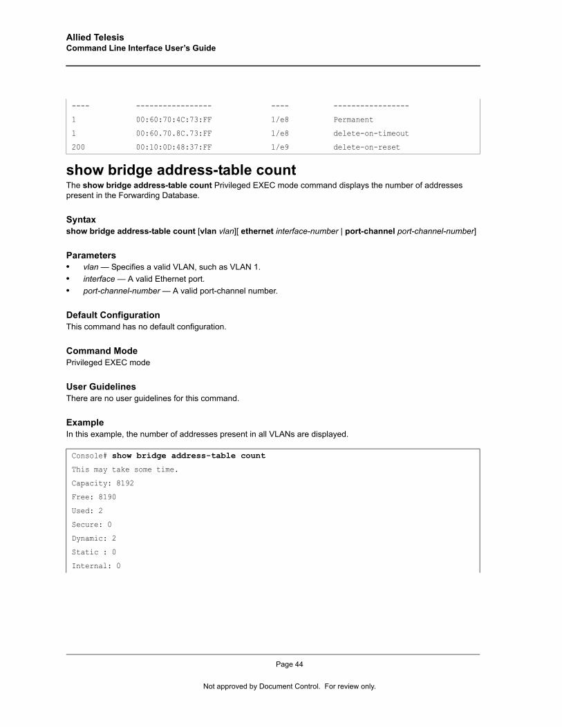
Allied Telesis Command Line Interface User’s Guide
show bridge address-table countThe show bridge address-table count Privileged EXEC mode command displays the number of addresses present in the Forwarding Database.
Syntaxshow bridge address-table count [vlan vlan][ ethernet interface-number | port-channel port-channel-number]
Parameters• vlan — Specifies a valid VLAN, such as VLAN 1.• interface — A valid Ethernet port.• port-channel-number — A valid port-channel number.
Default Configuration This command has no default configuration.
Command ModePrivileged EXEC mode
User GuidelinesThere are no user guidelines for this command.
ExampleIn this example, the number of addresses present in all VLANs are displayed.
---- ----------------- ---- -----------------
1 00:60:70:4C:73:FF 1/e8 Permanent
1 00:60.70.8C.73:FF 1/e8 delete-on-timeout
200 00:10:0D:48:37:FF 1/e9 delete-on-reset
Console# show bridge address-table count
This may take some time.
Capacity: 8192
Free: 8190
Used: 2
Secure: 0
Dynamic: 2
Static : 0
Internal: 0
Page 44
Not approved by Document Control. For review only.
Address Table Commands
show bridge multicast address-tableThe show bridge multicast address-table Privileged EXEC mode command displays the bridge Multicast Address Table information.
Syntaxshow bridge multicast address-table [vlan vlan-id] [address mac-multicast-address | ip-multicast-address] [format ip | format mac] [source ip-address]
Parameters• vlan-id — A valid VLAN ID value.• mac-multicast-address — A valid MAC Multicast address.• ip-multicast-address — A valid IP Multicast address.• ip-address — Source IP address• format ip|mac — Multicast address format. Can be ip or mac. If the format is unspecified, the default is mac.
Default Configuration This command has no default configuration.
Command ModePrivileged EXEC mode
User GuidelinesA MAC address can be displayed in IP format only if it is in the range of 0100.5e00.0000-0100.5e7f.ffff.
Page 45
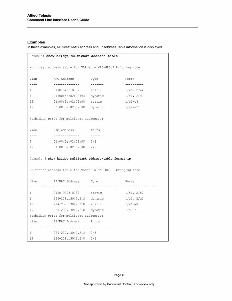
Allied Telesis Command Line Interface User’s Guide
ExamplesIn these examples, Multicast MAC address and IP Address Table information is displayed.
Console# show bridge multicast address-table
Multicast address table for VLANs in MAC-GROUP bridging mode:
Vlan MAC Address Type Ports
---- -------------- ------- ----------
1 0100.5e23.8787 static 1/e1, 2/e2
1 01:00:5e:02:02:03 dynamic 1/e1, 2/e2
19 01:00:5e:02:02:08 static 1/e1-e8
19 00:00:5e:02:02:08 dynamic 1/e9-e11
Forbidden ports for multicast addresses:
Vlan MAC Address Ports
---- -------------- -----
1 01:00:5e:02:02:03 2/8
19 01:00:5e:02:02:08 2/8
Console # show bridge multicast address-table format ip
Multicast address table for VLANs in MAC-GROUP bridging mode:
Vlan IP/MAC Address Type Ports
---------- --------------- ---------------- ------------------
1 0100.9923.8787 static 1/e1, 2/e2
1 224-239.130|2.2.3 dynamic 1/e1, 2/e2
19 224-239.130|2.2.8 static 1/e1-e8
19 224-239.130|2.2.8 dynamic 1/e9-e11
Forbidden ports for multicast addresses:
Vlan IP/MAC Address Ports
--------- ---------------- -----------
1 224-239.130|2.2.3 2/8
19 224-239.130|2.2.8 2/8
Page 46
Not approved by Document Control. For review only.
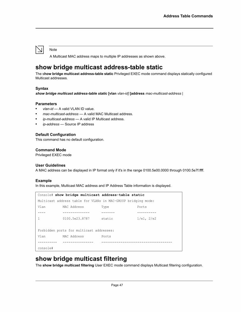
Address Table Commands
Note
A Multicast MAC address maps to multiple IP addresses as shown above.
show bridge multicast address-table staticThe show bridge multicast address-table static Privileged EXEC mode command displays statically configured Multicast addresses.
Syntaxshow bridge multicast address-table static [vlan vlan-id] [address mac-multicast-address |
Parameters• vlan-id — A valid VLAN ID value.• mac-multicast-address — A valid MAC Multicast address.• ip-multicast-address — A valid IP Multicast address.• ip-address — Source IP address
Default Configuration This command has no default configuration.
Command ModePrivileged EXEC mode
User GuidelinesA MAC address can be displayed in IP format only if it's in the range 0100.5e00.0000 through 0100.5e7f.ffff.
ExampleIn this example, Multicast MAC address and IP Address Table information is displayed.
show bridge multicast filteringThe show bridge multicast filtering User EXEC mode command displays Multicast filtering configuration.
Console# show bridge multicast address-table static
Multicast address table for VLANs in MAC-GROUP bridging mode:
Vlan MAC Address Type Ports
---- -------------- ------- ----------
1 0100.5e23.8787 static 1/e1, 2/e2
Forbidden ports for multicast addresses:
Vlan MAC Address Ports
---------- ---------------- -------------------------------------
console#
Page 47
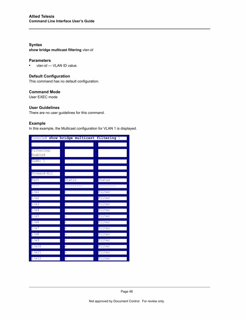
Allied Telesis Command Line Interface User’s Guide
Syntaxshow bridge multicast filtering vlan-id
Parameters• vlan-id — VLAN ID value.
Default ConfigurationThis command has no default configuration.
Command ModeUser EXEC mode
User GuidelinesThere are no user guidelines for this command.
ExampleIn this example, the Multicast configuration for VLAN 1 is displayed.
Console# show bridge multicast filtering 1
Filtering: Enabled
VLAN: 1
Forward-All
Port Static Status
---- --------- ---------
1/e1 - Filter
1/e2 - Filter
1/e3 - Filter
1/e4 - Filter
1/e5 - Filter
1/e6 - Filter
1/e7 - Filter
1/e8 - Filter
1/e9 - Filter
1/e10 - Filter
1/e11 - Filter
1/e12 - Filter
Page 48
Not approved by Document Control. For review only.
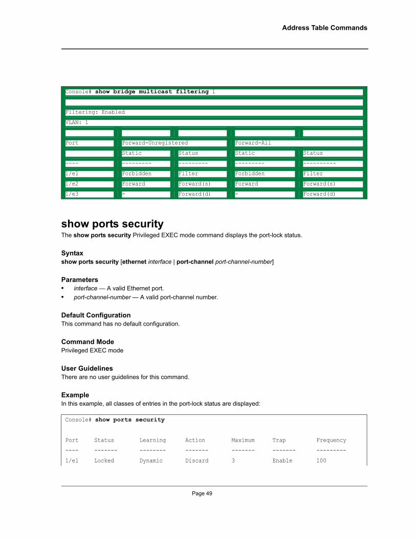
Address Table Commands
show ports securityThe show ports security Privileged EXEC mode command displays the port-lock status.
Syntaxshow ports security [ethernet interface | port-channel port-channel-number]
Parameters• interface — A valid Ethernet port.• port-channel-number — A valid port-channel number.
Default Configuration This command has no default configuration.
Command ModePrivileged EXEC mode
User GuidelinesThere are no user guidelines for this command.
ExampleIn this example, all classes of entries in the port-lock status are displayed:
Console# show bridge multicast filtering 1
Filtering: Enabled
VLAN: 1
Port Forward-Unregistered Forward-All
Static Status Static Status
---- --------- --------- --------- ----------
1/e1 Forbidden Filter Forbidden Filter
1/e2 Forward Forward(s) Forward Forward(s)
1/e3 - Forward(d) - Forward(d)
Console# show ports security
Port Status Learning Action Maximum Trap Frequency
---- ------- -------- ------- ------- ------- ---------
1/e1 Locked Dynamic Discard 3 Enable 100
Page 49
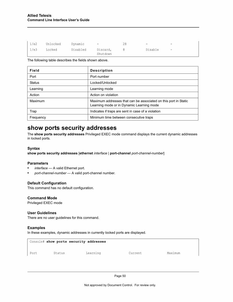
Allied Telesis Command Line Interface User’s Guide
The following table describes the fields shown above.
show ports security addressesThe show ports security addresses Privileged EXEC mode command displays the current dynamic addresses in locked ports.
Syntaxshow ports security addresses [ethernet interface | port-channel port-channel-number]
Parameters• interface — A valid Ethernet port.• port-channel-number — A valid port-channel number.
Default Configuration This command has no default configuration.
Command ModePrivileged EXEC mode
User GuidelinesThere are no user guidelines for this command.
ExamplesIn these examples, dynamic addresses in currently locked ports are displayed.
1/e2 Unlocked Dynamic - 28 - -
1/e3 Locked Disabled Discard, Shutdown
8 Disable -
Field Description
Port Port number
Status Locked/Unlocked
Learning Learning mode
Action Action on violation
Maximum Maximum addresses that can be associated on this port in Static Learning mode or in Dynamic Learning mode
Trap Indicates if traps are sent in case of a violation
Frequency Minimum time between consecutive traps
Console# show ports security addresses
Port Status Learning Current Maximum
Page 50
Not approved by Document Control. For review only.
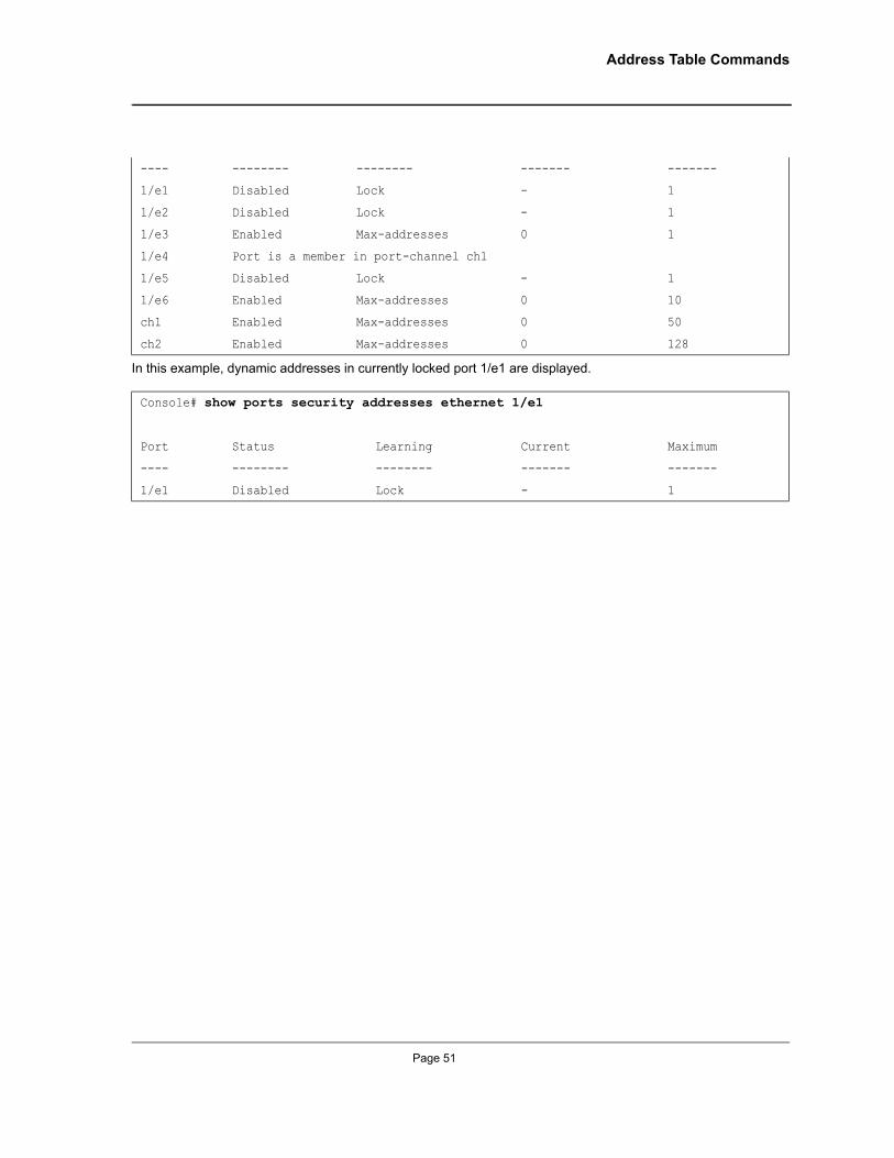
Address Table Commands
In this example, dynamic addresses in currently locked port 1/e1 are displayed.
---- -------- -------- ------- -------
1/e1 Disabled Lock - 1
1/e2 Disabled Lock - 1
1/e3 Enabled Max-addresses 0 1
1/e4 Port is a member in port-channel ch1
1/e5 Disabled Lock - 1
1/e6 Enabled Max-addresses 0 10
ch1 Enabled Max-addresses 0 50
ch2 Enabled Max-addresses 0 128
Console# show ports security addresses ethernet 1/e1
Port Status Learning Current Maximum
---- -------- -------- ------- -------
1/e1 Disabled Lock - 1
Page 51
Allied Telesis Command Line Interface User’s Guide
Chapter 5. Clock Commands
clock setThe clock set Privileged EXEC mode command manually sets the system clock. To avoid an SNTP conflict, this command should only be used if there is no clock source set.
Syntaxclock set hh:mm:ss day month year
or
clock set hh:mm:ss month day year
Parameters• hh:mm:ss — Current time in hours (military format), minutes, and seconds (hh: 0 - 23, mm: 0 - 59, ss: 0 - 59).• day — Current day (by date) in the month (1 - 31).• month — Current month using the first three letters by name (Jan, …, Dec).• year — Current year (2000 - 2097).
Default ConfigurationThis command has no default configuration.
Command ModePrivileged EXEC mode
User GuidelinesThere are no user guidelines for this command.
ExampleThe following example sets the system time to 13:32:00 on the 7th March 2002.
clock sourceThe clock source Global Configuration mode command configures an external time source for the system clock. Use no form of this command to disable external time source.
Syntaxclock source {sntp}
no clock source
Parameters• sntp — SNTP servers
Console# clock set 13:32:00 7 Mar 2002
Page 52
Not approved by Document Control. For review only.
Clock Commands
Default ConfigurationNo external clock source
Command ModeGlobal Configuration mode
User GuidelinesThere are no user guidelines for this command.
ExampleThe following example configures an external time source for the system clock.
clock timezoneThe clock timezone Global Configuration mode command sets the time zone for display purposes. Use the no form of this command to set the time to the Coordinated Universal Time (UTC).
Syntaxclock timezone hours-offset [minutes minutes-offset] [zone acronym]
no clock timezone
Parameters• hours-offset — Hours difference from UTC. (Range: -12 – +13)• minutes-offset — Minutes difference from UTC. (Range: 1 – 59)• acronym — The acronym of the time zone. (Range: Up to 4 characters)
Default ConfigurationClock set to UTC.
Command ModeGlobal Configuration mode
User GuidelinesThe system internally keeps time in UTC, so this command is used only for display purposes and when the time is manually set.
ExampleThe following example sets the timezone to 6 hours difference from UTC.
Console(config)# clock source sntp
Console(config)# clock timezone -6 zone CST
Page 53
Allied Telesis Command Line Interface User’s Guide
clock summer-timeThe clock summer-time Global Configuration mode command configures the system to automatically switch to summer time (daylight saving time). Use the no form of this command to configure the software not to automatically switch to summer time.
Syntaxclock summer-time recurring {usa | eu | {week day month hh:mm week day month hh:mm}} [offset offset] [zone acronym]
clock summer-time date date month year hh:mm date month year hh:mm [offset offset] [zone acronym]
clock summer-time date month date year hh:mm month date year hh:mm [offset offset] [zone acronym]
no clock summer-time recurring
Parameters• recurring — Indicates that summer time should start and end on the corresponding specified days every
year. • date — Indicates that summer time should start on the first specific date listed in the command and end on
the second specific date in the command.• usa — The summer time rules are the United States rules.• eu — The summer time rules are the European Union rules.• week — Week of the month. (Range: 1 - 5, first, last)• day — Day of the week (Range: first three letters by name, like sun)• date — Date of the month. (Range:1 - 31)• month — Month. (Range: first three letters by name, like Jan)• year — year - no abbreviation (Range: 2000 - 2097)• hh:mm — Time in military format, in hours and minutes. (Range: hh: 0 - 23, mm:0 - 59)• offset — Number of minutes to add during summer time. (Range: 1 - 1440)• acronym — The acronym of the time zone to be displayed when summer time is in effect. (Range: Up to 4
characters)
Default ConfigurationSummer time is disabled.
offset — Default is 60 minutes.
acronym — If unspecified default to the timezone acronym.
If the timezone has not been defined, the default is GMT.
Command ModeGlobal Configuration mode
Page 54
Not approved by Document Control. For review only.

Clock Commands
User GuidelinesIn both the date and recurring forms of the command, the first part of the command specifies when summer time begins, and the second part specifies when it ends. All times are relative to the local time zone. The start time is relative to standard time. The end time is relative to summer time. If the starting month is chronologically after the ending month, the system assumes that the device is in the southern hemisphere.
USA rule for daylight savings time:
• Start: Second Sunday in March• End: First Sunday in November • Time: 2 am local timeEU rule for daylight savings time:
• Start: Last Sunday in March • End: Last Sunday in October • Time: 1.00 am (01:00)
ExampleThe following example sets summer time starting on the first Sunday in April at 2 am and finishing on the last Sunday in October at 2 am.
sntp authentication-keyThe sntp authentication-key Global Configuration mode command defines an authentication key for Simple Network Time Protocol (SNTP). Use the no form of this command to remove the authentication key for SNTP.
Syntaxsntp authentication-key number md5 value
no sntp authentication-key number
Parameters• number — Key number (Range: 1-4294967295)• value — Key value (Range: 1-8 characters)
Default ConfigurationNo authentication key is defined.
Command ModeGlobal Configuration mode
User GuidelinesMultiple keys can be generated.
Console(config)# clock summer-time recurring first sun apr 2:00 last sun oct 2:00
Page 55
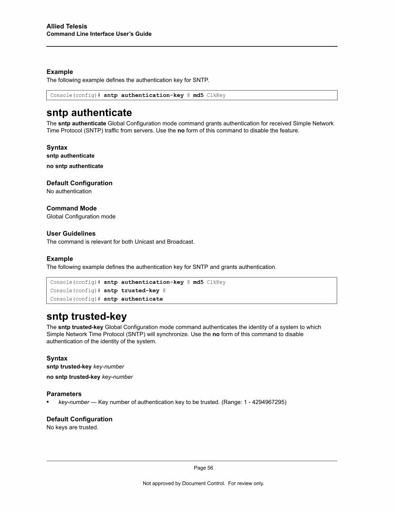
Allied Telesis Command Line Interface User’s Guide
ExampleThe following example defines the authentication key for SNTP.
sntp authenticateThe sntp authenticate Global Configuration mode command grants authentication for received Simple Network Time Protocol (SNTP) traffic from servers. Use the no form of this command to disable the feature.
Syntaxsntp authenticate
no sntp authenticate
Default ConfigurationNo authentication
Command ModeGlobal Configuration mode
User GuidelinesThe command is relevant for both Unicast and Broadcast.
ExampleThe following example defines the authentication key for SNTP and grants authentication.
sntp trusted-keyThe sntp trusted-key Global Configuration mode command authenticates the identity of a system to which Simple Network Time Protocol (SNTP) will synchronize. Use the no form of this command to disable authentication of the identity of the system.
Syntaxsntp trusted-key key-number
no sntp trusted-key key-number
Parameters• key-number — Key number of authentication key to be trusted. (Range: 1 - 4294967295)
Default ConfigurationNo keys are trusted.
Console(config)# sntp authentication-key 8 md5 ClkKey
Console(config)# sntp authentication-key 8 md5 ClkKeyConsole(config)# sntp trusted-key 8Console(config)# sntp authenticate
Page 56
Not approved by Document Control. For review only.
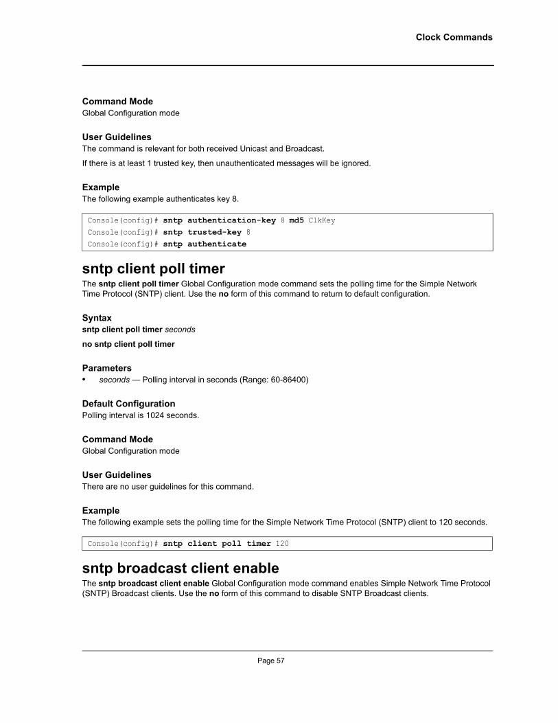
Clock Commands
Command ModeGlobal Configuration mode
User GuidelinesThe command is relevant for both received Unicast and Broadcast.
If there is at least 1 trusted key, then unauthenticated messages will be ignored.
ExampleThe following example authenticates key 8.
sntp client poll timerThe sntp client poll timer Global Configuration mode command sets the polling time for the Simple Network Time Protocol (SNTP) client. Use the no form of this command to return to default configuration.
Syntaxsntp client poll timer seconds
no sntp client poll timer
Parameters• seconds — Polling interval in seconds (Range: 60-86400)
Default ConfigurationPolling interval is 1024 seconds.
Command ModeGlobal Configuration mode
User GuidelinesThere are no user guidelines for this command.
ExampleThe following example sets the polling time for the Simple Network Time Protocol (SNTP) client to 120 seconds.
sntp broadcast client enableThe sntp broadcast client enable Global Configuration mode command enables Simple Network Time Protocol (SNTP) Broadcast clients. Use the no form of this command to disable SNTP Broadcast clients.
Console(config)# sntp authentication-key 8 md5 ClkKeyConsole(config)# sntp trusted-key 8Console(config)# sntp authenticate
Console(config)# sntp client poll timer 120
Page 57
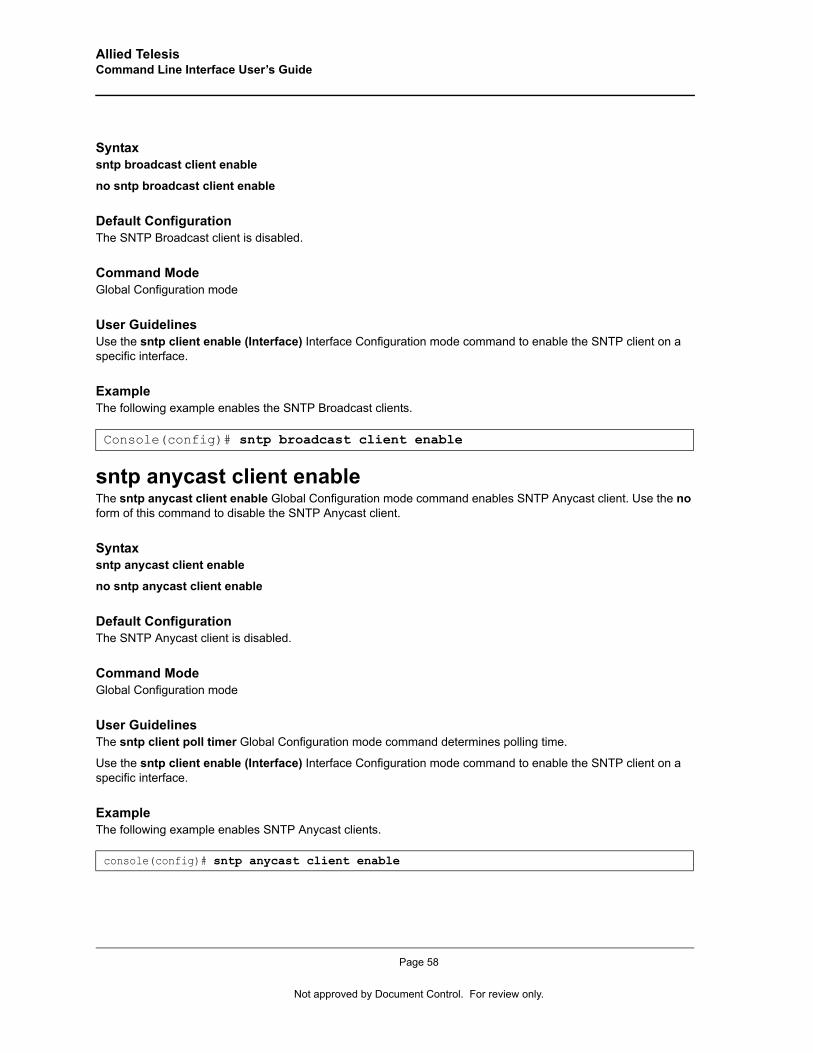
Allied Telesis Command Line Interface User’s Guide
Syntaxsntp broadcast client enable
no sntp broadcast client enable
Default ConfigurationThe SNTP Broadcast client is disabled.
Command ModeGlobal Configuration mode
User GuidelinesUse the sntp client enable (Interface) Interface Configuration mode command to enable the SNTP client on a specific interface.
ExampleThe following example enables the SNTP Broadcast clients.
sntp anycast client enableThe sntp anycast client enable Global Configuration mode command enables SNTP Anycast client. Use the no form of this command to disable the SNTP Anycast client.
Syntaxsntp anycast client enable
no sntp anycast client enable
Default ConfigurationThe SNTP Anycast client is disabled.
Command ModeGlobal Configuration mode
User GuidelinesThe sntp client poll timer Global Configuration mode command determines polling time.
Use the sntp client enable (Interface) Interface Configuration mode command to enable the SNTP client on a specific interface.
ExampleThe following example enables SNTP Anycast clients.
Console(config)# sntp broadcast client enable
console(config)# sntp anycast client enable
Page 58
Not approved by Document Control. For review only.

Clock Commands
sntp client enable (Interface)The sntp client enable Interface Configuration (Ethernet, port-channel, VLAN) mode command enables the Simple Network Time Protocol (SNTP) client on an interface. This applies to both receive Broadcast and Anycast updates. Use the no form of this command to disable the SNTP client.
Syntaxsntp client enable
no sntp client enable
Default ConfigurationThe SNTP client is disabled on an interface.
Command ModeInterface configuration (Ethernet, port-channel, VLAN) mode
User GuidelinesUse the sntp broadcast client enable Global Configuration mode command to enable Broadcast clients globally.
Use the sntp anycast client enable Global Configuration mode command to enable Anycast clients globally.
ExampleThe following example enables the SNTP client on Ethernet port 1/e3.
sntp unicast client enableThe sntp unicast client enable Global Configuration mode command enables the device to use the Simple Network Time Protocol (SNTP) to request and accept SNTP traffic from servers. Use the no form of this command to disable requesting and accepting SNTP traffic from servers.
Syntaxsntp unicast client enable
no sntp unicast client enable
Default ConfigurationThe SNTP Unicast client is disabled.
Command ModeGlobal Configuration mode
User GuidelinesUse the sntp server Global Configuration mode command to define SNTP servers.
onsole(config)# interface ethernet 1/e3Console(config-if)# sntp client enable
Page 59

Allied Telesis Command Line Interface User’s Guide
ExampleThe following example enables the device to use the Simple Network Time Protocol (SNTP) to request and accept SNTP traffic from servers.
sntp unicast client pollThe sntp unicast client poll Global Configuration mode command enables polling for the Simple Network Time Protocol (SNTP) predefined Unicast servers. Use the no form of this command to disable the polling for SNTP client.
Syntaxsntp unicast client poll
no sntp unicast client poll
Default ConfigurationPolling is disabled.
Command ModeGlobal Configuration mode
User GuidelinesThe sntp client poll timer Global Configuration mode command determines polling time.
ExampleThe following example enables polling for Simple Network Time Protocol (SNTP) predefined Unicast clients.
sntp serverThe sntp server Global Configuration mode command configures the device to use the Simple Network Time Protocol (SNTP) to request and accept SNTP traffic from a specified server. Use the no form of this command to remove a server from the list of SNTP servers.
Syntaxsntp server {ip-address | hostname}[poll] [key keyid]
no sntp server host
Parameters• ip-address — IP address of the server. • hostname — Hostname of the server. (Range: 1-158 characters) • poll — Enable polling.• keyid — Authentication key to use when sending packets to this peer.
(Range:1-4294967295)
Console(config)# sntp unicast client enable
Console(config)# sntp unicast client poll
Page 60
Not approved by Document Control. For review only.

Clock Commands
Default ConfigurationNo servers are defined.
Command ModeGlobal Configuration mode
User GuidelinesUp to 8 SNTP servers can be defined.
To enable predefined Unicast clients globally use the sntp unicast client enable Global Configuration mode command.
To enabling global polling use the sntp unicast client poll Global Configuration mode command.
The sntp client poll timer Global Configuration mode command determines polling time.
ExampleThe following example configures the device to accept SNTP traffic from the server on 192.1.1.1.
show clockThe show clock User EXEC mode command displays the time and date from the system clock.
Syntaxshow clock [detail]
Parameters• detail — Shows timezone and summertime configuration.
Default ConfigurationThis command has no default configuration.
Command ModeUser EXEC mode
User GuidelinesThe symbol that precedes the show clock display indicates the following:
Console(config)# sntp server 192.1.1.1
Symbol Description
* Time is not authoritative.
(blank) Time is authoritative.
. Time is authoritative, but SNTP is not synchronized.
Page 61
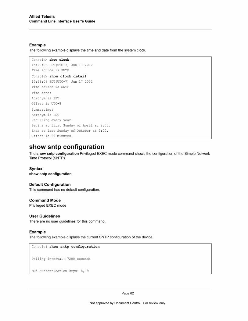
Allied Telesis Command Line Interface User’s Guide
ExampleThe following example displays the time and date from the system clock.
show sntp configurationThe show sntp configuration Privileged EXEC mode command shows the configuration of the Simple Network Time Protocol (SNTP).
Syntaxshow sntp configuration
Default ConfigurationThis command has no default configuration.
Command ModePrivileged EXEC mode
User GuidelinesThere are no user guidelines for this command.
ExampleThe following example displays the current SNTP configuration of the device.
Console> show clock15:29:03 PDT(UTC-7) Jun 17 2002
Time source is SNTP
Console> show clock detail15:29:03 PDT(UTC-7) Jun 17 2002
Time source is SNTP
Time zone:
Acronym is PSTOffset is UTC-8
Summertime:
Acronym is PDT
Recurring every year.Begins at first Sunday of April at 2:00.
Ends at last Sunday of October at 2:00.
Offset is 60 minutes.
Console# show sntp configuration
Polling interval: 7200 seconds
MD5 Authentication keys: 8, 9
Page 62
Not approved by Document Control. For review only.
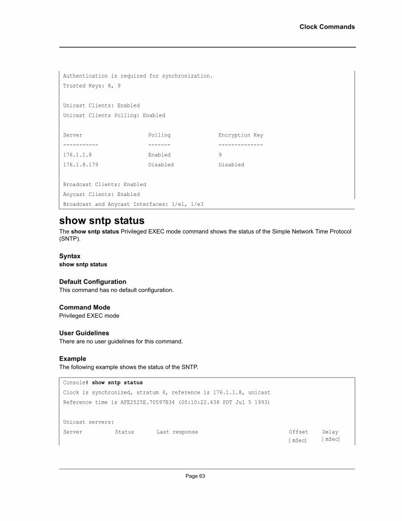
Clock Commands
show sntp statusThe show sntp status Privileged EXEC mode command shows the status of the Simple Network Time Protocol (SNTP).
Syntaxshow sntp status
Default ConfigurationThis command has no default configuration.
Command ModePrivileged EXEC mode
User GuidelinesThere are no user guidelines for this command.
ExampleThe following example shows the status of the SNTP.
Authentication is required for synchronization.
Trusted Keys: 8, 9
Unicast Clients: Enabled
Unicast Clients Polling: Enabled
Server Polling Encryption Key
----------- ------- --------------
176.1.1.8 Enabled 9
176.1.8.179 Disabled Disabled
Broadcast Clients: Enabled
Anycast Clients: Enabled
Broadcast and Anycast Interfaces: 1/e1, 1/e3
Console# show sntp status
Clock is synchronized, stratum 4, reference is 176.1.1.8, unicast
Reference time is AFE2525E.70597B34 (00:10:22.438 PDT Jul 5 1993)
Unicast servers:
Server Status Last response Offset
[mSec]
Delay [mSec]
Page 63
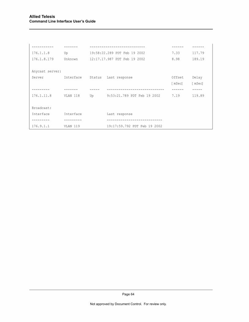
Allied Telesis Command Line Interface User’s Guide
----------- ------- ---------------------------- ------ ------
176.1.1.8 Up 19:58:22.289 PDT Feb 19 2002 7.33 117.79
176.1.8.179 Unknown 12:17.17.987 PDT Feb 19 2002 8.98 189.19
Anycast server:
Server Interface Status Last response Offset Delay
[mSec] [mSec]
--------- ------- ----- ----------------------------- ------ -----
176.1.11.8 VLAN 118 Up 9:53:21.789 PDT Feb 19 2002 7.19 119.89
Broadcast:
Interface Interface Last response
--------- --------- ----------------------------
176.9.1.1 VLAN 119 19:17:59.792 PDT Feb 19 2002
Page 64
Not approved by Document Control. For review only.
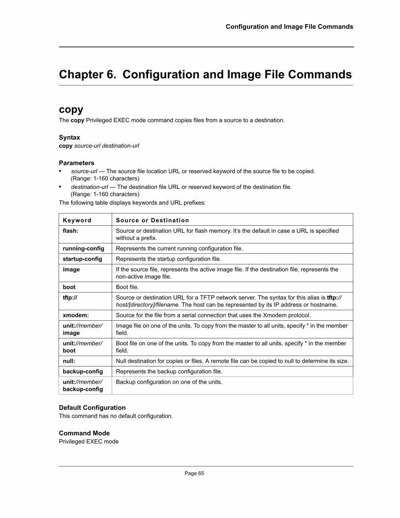
Configuration and Image File Commands
Chapter 6. Configuration and Image File Commands
copyThe copy Privileged EXEC mode command copies files from a source to a destination.
Syntaxcopy source-url destination-url
Parameters• source-url — The source file location URL or reserved keyword of the source file to be copied.
(Range: 1-160 characters)• destination-url — The destination file URL or reserved keyword of the destination file.
(Range: 1-160 characters)The following table displays keywords and URL prefixes:
Default ConfigurationThis command has no default configuration.
Command ModePrivileged EXEC mode
Keyword Source or Destination
flash: Source or destination URL for flash memory. It’s the default in case a URL is specified without a prefix.
running-config Represents the current running configuration file.
startup-config Represents the startup configuration file.
image If the source file, represents the active image file. If the destination file, represents the non-active image file.
boot Boot file.
tftp:// Source or destination URL for a TFTP network server. The syntax for this alias is tftp://host/[directory]/filename. The host can be represented by its IP address or hostname.
xmodem: Source for the file from a serial connection that uses the Xmodem protocol.
unit://member/image
Image file on one of the units. To copy from the master to all units, specify * in the member field.
unit://member/boot
Boot file on one of the units. To copy from the master to all units, specify * in the member field.
null: Null destination for copies or files. A remote file can be copied to null to determine its size.
backup-config Represents the backup configuration file.
unit://member/backup-config
Backup configuration on one of the units.
Page 65
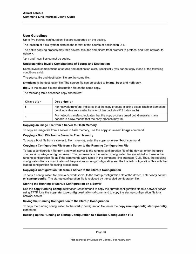
Allied Telesis Command Line Interface User’s Guide
User GuidelinesUp to five backup configuration files are supported on the device.
The location of a file system dictates the format of the source or destination URL.
The entire copying process may take several minutes and differs from protocol to protocol and from network to network.
*.prv and *.sys files cannot be copied.
Understanding Invalid Combinations of Source and Destination
Some invalid combinations of source and destination exist. Specifically, you cannot copy if one of the following conditions exist:
The source file and destination file are the same file.
xmodem: is the destination file. The source file can be copied to image, boot and null: only.
tftp:// is the source file and destination file on the same copy.
The following table describes copy characters:
Copying an Image File from a Server to Flash Memory
To copy an image file from a server to flash memory, use the copy source-url image command.
Copying a Boot File from a Server to Flash Memory
To copy a boot file from a server to flash memory, enter the copy source-url boot command.
Copying a Configuration File from a Server to the Running Configuration File
To load a configuration file from a network server to the running configuration file of the device, enter the copy source-url running-config command. The commands in the loaded configuration file are added to those in the running configuration file as if the commands were typed in the command-line interface (CLI). Thus, the resulting configuration file is a combination of the previous running configuration and the loaded configuration files with the loaded configuration file taking precedence.
Copying a Configuration File from a Server to the Startup Configuration
To copy a configuration file from a network server to the startup configuration file of the device, enter copy source-url startup-config. The startup configuration file is replaced by the copied configuration file.
Storing the Running or Startup Configuration on a Server
Use the copy running-config destination-url command to copy the current configuration file to a network server using TFTP. Use the copy startup-config destination-url command to copy the startup configuration file to a network server.
Saving the Running Configuration to the Startup Configuration
To copy the running configuration to the startup configuration file, enter the copy running-config startup-config command.
Backing up the Running or Startup Configuration to a Backup Configuration File
Character Description
! For network transfers, indicates that the copy process is taking place. Each exclamation point indicates successful transfer of ten packets (512 bytes each).
. For network transfers, indicates that the copy process timed out. Generally, many periods in a row means that the copy process may fail.
Page 66
Not approved by Document Control. For review only.
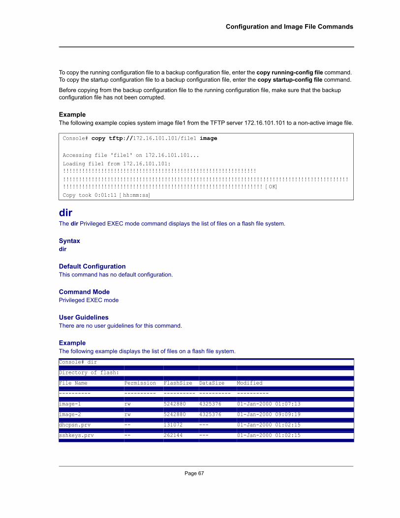
Configuration and Image File Commands
To copy the running configuration file to a backup configuration file, enter the copy running-config file command. To copy the startup configuration file to a backup configuration file, enter the copy startup-config file command.
Before copying from the backup configuration file to the running configuration file, make sure that the backup configuration file has not been corrupted.
ExampleThe following example copies system image file1 from the TFTP server 172.16.101.101 to a non-active image file.
dirThe dir Privileged EXEC mode command displays the list of files on a flash file system.
Syntaxdir
Default ConfigurationThis command has no default configuration.
Command ModePrivileged EXEC mode
User GuidelinesThere are no user guidelines for this command.
ExampleThe following example displays the list of files on a flash file system.
Console# copy tftp://172.16.101.101/file1 image Accessing file 'file1' on 172.16.101.101...
Loading file1 from 172.16.101.101: !!!!!!!!!!!!!!!!!!!!!!!!!!!!!!!!!!!!!!!!!!!!!!!!!!!!!!!!!!!!!
!!!!!!!!!!!!!!!!!!!!!!!!!!!!!!!!!!!!!!!!!!!!!!!!!!!!!!!!!!!!!!!!!!!!!!!!!!!!!!!!!!!!!!!!!!!!!!!!!!!!!!!!!!!!!!!!!!!!!!!!!!!!!!!!!!!!!!!!!!!!!!!!!!!!!!!!! [OK]
Copy took 0:01:11 [hh:mm:ss]
Console# dir
Directory of flash:
File Name Permission FlashSize DataSize Modified
---------- ---------- ---------- ---------- ----------
image-1 rw 5242880 4325376 01-Jan-2000 01:07:13
image-2 rw 5242880 4325376 01-Jan-2000 09:09:19
dhcpsn.prv -- 131072 --- 01-Jan-2000 01:02:15
sshkeys.prv -- 262144 --- 01-Jan-2000 01:02:15
Page 67
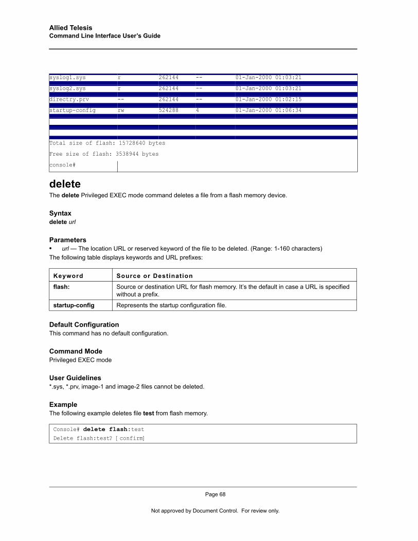
Allied Telesis Command Line Interface User’s Guide
deleteThe delete Privileged EXEC mode command deletes a file from a flash memory device.
Syntaxdelete url
Parameters• url — The location URL or reserved keyword of the file to be deleted. (Range: 1-160 characters)The following table displays keywords and URL prefixes:
Default ConfigurationThis command has no default configuration.
Command ModePrivileged EXEC mode
User Guidelines*.sys, *.prv, image-1 and image-2 files cannot be deleted.
ExampleThe following example deletes file test from flash memory.
syslog1.sys r 262144 -- 01-Jan-2000 01:03:21
syslog2.sys r 262144 -- 01-Jan-2000 01:03:21
directry.prv -- 262144 -- 01-Jan-2000 01:02:15
startup-config rw 524288 4 01-Jan-2000 01:06:34
Total size of flash: 15728640 bytes
Free size of flash: 3538944 bytes
console#
Keyword Source or Destination
flash: Source or destination URL for flash memory. It’s the default in case a URL is specified without a prefix.
startup-config Represents the startup configuration file.
Console# delete flash:testDelete flash:test? [confirm]
Page 68
Not approved by Document Control. For review only.
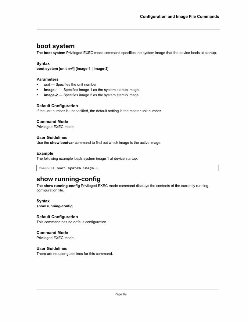
Configuration and Image File Commands
boot systemThe boot system Privileged EXEC mode command specifies the system image that the device loads at startup.
Syntaxboot system [unit unit] {image-1 | image-2}
Parameters• unit — Specifies the unit number.• image-1 — Specifies image 1 as the system startup image.• image-2 — Specifies image 2 as the system startup image.
Default ConfigurationIf the unit number is unspecified, the default setting is the master unit number.
Command ModePrivileged EXEC mode
User GuidelinesUse the show bootvar command to find out which image is the active image.
ExampleThe following example loads system image 1 at device startup.
show running-configThe show running-config Privileged EXEC mode command displays the contents of the currently running configuration file.
Syntaxshow running-config
Default ConfigurationThis command has no default configuration.
Command ModePrivileged EXEC mode
User GuidelinesThere are no user guidelines for this command.
Console# boot system image-1
Page 69

Allied Telesis Command Line Interface User’s Guide
ExampleThe following example displays the contents of the running configuration file.
show startup-configThe show startup-config Privileged EXEC mode command displays the contents of the startup configuration file.
Syntaxshow startup-config
Default ConfigurationThis command has no default configuration.
Command ModePrivileged EXEC mode
User GuidelinesThere are no user guidelines for this command.
ExampleThe following example displays the contents of the running configuration file.
Console# show running-configsoftware version 1.1
hostname device
interface ethernet 1/e1
ip address 176.242.100.100 255.255.255.0duplex full
speed 1000
interface ethernet 1/e2
ip address 176.243.100.100 255.255.255.0duplex full
speed 1000
Console# show startup-configsoftware version 1.1
hostname device
Page 70
Not approved by Document Control. For review only.
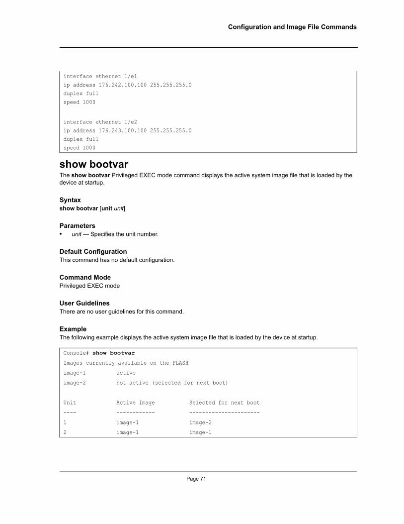
Configuration and Image File Commands
show bootvarThe show bootvar Privileged EXEC mode command displays the active system image file that is loaded by the device at startup.
Syntaxshow bootvar [unit unit]
Parameters• unit — Specifies the unit number.
Default ConfigurationThis command has no default configuration.
Command ModePrivileged EXEC mode
User GuidelinesThere are no user guidelines for this command.
ExampleThe following example displays the active system image file that is loaded by the device at startup.
interface ethernet 1/e1
ip address 176.242.100.100 255.255.255.0duplex full
speed 1000
interface ethernet 1/e2
ip address 176.243.100.100 255.255.255.0duplex full
speed 1000
Console# show bootvar
Images currently available on the FLASH
image-1 active
image-2 not active (selected for next boot)
Unit Active Image Selected for next boot
---- ------------ ----------------------
1 image-1 image-2
2 image-1 image-1
Page 71
Allied Telesis Command Line Interface User’s Guide
Chapter 7. DHCP Option 82 Commands
ip dhcp information optionThe ip dhcp information option Global Configuration mode command enables Dynamic Host Configuration Protocol (DHCP) option-82 data insertion. Use the no form of this command to disable DHCP option-82 data insertion.
Syntaxip dhcp information option
no ip dhcp information option
ParametersThis command has no arguments or keywords.
Default ConfigurationDHCP option-82 data insertion is enabled.
Command ModeGlobal Configuration mode
User GuidelinesDHCP option 82 is enabled only if DHCP snooping or DHCP relay are enabled.
ExampleThe following example enables DHCP option-82 data insertion.
show ip dhcp information optionThe show ip dhcp information option EXEC mode command displays the DHCP option 82 configuration.
Syntaxshow ip dhcp information option
ParametersThis command has no arguments or keywords.
Default ConfigurationDHCP option-82 data insertion is enabled.
Console(config)# ip dhcp information option
Page 72
Not approved by Document Control. For review only.
DHCP Option 82 Commands
Command ModePrivileged EXEC
User GuidelinesThere are no user guidelines for this command.
ExampleThe following example displays the DHCP option 82 configuration.
ip dhcp relay enableThe ip dhcp relay enable Global Configuration mode command enables DHCP relay features on your router. Use the no form of this command to disable the relay agent features.
Syntaxip dhcp relay {address|enable}
no ip dhcp relay {address|enable}
ParametersThis command has no arguments or keywords.
Default ConfigurationDisabled.
Command ModeGlobal Configuration
User GuidelinesThere are no user guidelines for this command.
ExampleThe following example enables DHCP relay features.
Console(config)# show ip dhcp information option
Console(config)# ip dhcp relay enable
Page 73
Allied Telesis Command Line Interface User’s Guide
Chapter 8. DHCP Snooping Commands
ip dhcp snoopingThe ip dhcp snooping Global Configuration mode command globally enables DHCP snooping. Use the no form of this command to return to the default setting.
Syntaxip dhcp snooping
no ip dhcp snooping
ParametersThis command has no arguments or keywords
Default ConfigurationDisabled
Command ModeGlobal Configuration mode
User GuidelinesFor any DHCP snooping configuration to take effect, DHCP snooping must be globally enabled. DHCP snooping is not active until snooping on a VLAN is enabled by using the ip dhcp snooping VLAN Global Configuration mode command.
Example.The following example configures globally enabling DHCP snooping.
ip dhcp snooping vlanThe ip dhcp snooping vlan Global Configuration mode command enables DHCP snooping on a VLAN. Use the no form of this command to disable DHCP snooping on a VLAN
Syntaxip dhcp snooping vlan vlan-id
no ip dhcp snooping vlan vlan-id
Parameters• vlan-id — Specify VLAN ID.
Default ConfigurationDisabled
Console(config)# ip dhcp snooping
Page 74
Not approved by Document Control. For review only.
DHCP Snooping Commands
Command ModeGlobal Configuration mode
User GuidelinesDHCP snooping must be first globally enabled before enabling DHCP snooping on a VLAN.
ExampleThe following example configures DHCP snooping on a VLAN.
ip dhcp snooping trustThe ip dhcp snooping trust Interface Configuration mode command configures a port as trusted for DHCP snooping purposes. Use the no form of this command to return to the default setting.
Syntaxip dhcp snooping trust
no ip dhcp snooping trust
ParametersThis command has no arguments or keywords.
Default ConfigurationInterface configuration (Ethernet, Port-channel)
Command ModeInterface Configuration mode
User GuidelinesConfigure as trusted ports those that are connected to a DHCP server or to other switches or routers. Configure as untrusted ports those that are connected to DHCP clients.
Example.The following example configures a port as trusted for DHCP snooping purposes.
Console(config)# ip dhcp snooping vlan 1
console#console# configure
console(config)# interface ethernet 1/e1console(config-if)# ip dhcp snooping trustconsole(config-if)#
Page 75
Allied Telesis Command Line Interface User’s Guide
ip dhcp snooping information option allowed-untrustedThe ip dhcp snooping information option allowed-untrusted Global Configuration mode command configures a switch to accept DHCP packets with option-82 information from an untrusted port. Use the no form of this command to configure the switch to drop these packets from an untrusted port.
Syntaxip dhcp snooping information option allowed-untrusted
no ip dhcp snooping information option allowed-untrusted
ParametersThis command has no arguments or keywords.
Default Configuration
Discard DHCP packets with option-82 information from an untrusted port.
Command ModeGlobal Configuration mode
User GuidelinesThere are no user guidelines for this command.
ExampleThe following example configures the switch to accept DHCP packets with option-82 information from an untrusted port.
ip dhcp snooping verifyThe ip dhcp snooping verify Global Configuration mode command configures the switch to verify, on an untrusted port, that the source MAC address in a DHCP packet matches the client hardware address. Use the no form of this command to configure the switch to not verify the MAC addresses.
Syntaxip dhcp snooping verify
no ip dhcp snooping verify
ParametersThis command has no arguments or keywords.
Default ConfigurationThe switch verifies the source MAC address in a DHCP packet that is received on untrusted ports matches the client hardware address in the packet.
Command ModeGlobal configuration.
Console(config)# ip dhcp snooping information option allowed-untrusted
Page 76
Not approved by Document Control. For review only.
DHCP Snooping Commands
User GuidelinesThere are no user guidelines for this command.
ExampleThe following example configures the switch to verify on an untrusted port that the source MAC address in a DHCP packet matches the client hardware address
ip dhcp snooping databaseThe ip dhcp snooping database Global Configuration mode command configures the DHCP snooping binding file. Use the no form of this command to delete the binding file.
Syntaxip dhcp snooping database
no ip dhcp snooping database
ParametersThis command has no arguments or keywords.
Default ConfigurationThe URL is not defined.
Command ModeGlobal Configuration mode
User GuidelinesTo ensure that the lease time in the database is accurate, Simple Network Time Protocol (SNTP) is enabled and configured.
The switch writes binding changes to the binding file only when the switch system clock is synchronized with SNTP.
Example.The following example configures the DHCP snooping binding file.
ip dhcp snooping database update-freqThe ip dhcp snooping database update-freq Global Configuration mode command configures the update frequency of the DHCP snooping binding file. Use the no form of this command to return to default.
Syntaxip dhcp snooping database update-freq seconds
Console(config) #ip dhcp snooping verify
Console(config)# ip dhcp snooping database
Page 77
Allied Telesis Command Line Interface User’s Guide
no ip dhcp snooping database update-freq
Parameters• seconds — Specify, in seconds, the update frequency (Range: 600 - 86400 ).
Default Configuration1200
Command ModeGlobal Configuration mode
User GuidelinesThere are no user guidelines for this command.
ExampleThe following example configures the update frequency of the DHCP snooping binding file.
ip dhcp snooping bindingThe ip dhcp snooping binding Privileged EXEC mode command configures the DHCP snooping binding database and adds binding entries to the database. Use the no form of this command to delete entries from the binding database.
Syntaxip dhcp snooping binding mac-address vlan-id ip-address {ethernet interface | port-channel port-channel-number} expiry seconds
no ip dhcp snooping binding mac-address vlan-id
Parameters• mac-address — Specify a MAC address• vlan-id — Specify a VLAN number• ip-address — Specify an IP address• interface — Specify Ethernet port• port-channel-number — Specify Port-channel number• expiry seconds — Specify the interval, in seconds, after which the binding entry is no longer valid (Range: 10
- 4294967295)
Default ConfigurationNo static binding exists
Command ModePrivileged EXEC
Console(config)# ip dhcp snooping database update-freq
Page 78
Not approved by Document Control. For review only.
DHCP Snooping Commands
User GuidelinesAfter entering this command an entry is added to the DHCP snooping database. If DHCP snooping binding file exists, the entry is added to that file also.
The entry is displayed in the show commands as a ‘DHCP Snooping entry’.
ExampleThe following example configures the DHCP snooping binding database and adds binding entries to the database.
clear ip dhcp snooping databaseThe clear ip dhcp snooping database Privileged EXEC mode command clears the DHCP binding database.
Syntaxclear ip dhcp snooping database
ParametersThis command has no arguments or keywords.
Default ConfigurationNo static binding exists
Command ModePrivileged EXEC mode
User GuidelinesThere are no user guidelines for this command.
ExampleThe following example clears the DHCP binding database.
show ip dhcp snoopingThe show ip dhcp snooping EXEC mode command displays the DHCP snooping configuration.
Syntaxshow ip dhcp snooping [ethernet interface | port-channel port-channel-number]
Parameters• interface — Specify Ethernet port• port-channel-number — Specify Port-channel number
Default ConfigurationThis command has no default configuration.
Console# ip dhcp snooping binding 0060.704c.73ff 3 10.1.8.1 ethernet 1/e21
Console# clear ip dhcp snooping database
Page 79
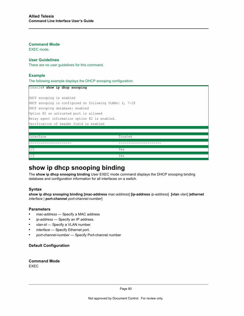
Allied Telesis Command Line Interface User’s Guide
Command ModeEXEC mode.
User GuidelinesThere are no user guidelines for this command.
Example The following example displays the DHCP snooping configuration.
show ip dhcp snooping bindingThe show ip dhcp snooping binding User EXEC mode command displays the DHCP snooping binding database and configuration information for all interfaces on a switch.
Syntaxshow ip dhcp snooping binding [mac-address mac-address] [ip-address ip-address] [vlan vlan] [ethernet interface | port-channel port-channel-number]
Parameters• mac-address — Specify a MAC address• ip-address — Specify an IP address.• vlan-id — Specify a VLAN number.• interface — Specify Ethernet port.• port-channel-number — Specify Port-channel number
Default Configuration
Command ModeEXEC
Console# show ip dhcp snooping
DHCP snooping is enabledDHCP snooping is configured on following VLANs: 2, 7-18
DHCP snooping database: enabled
Option 82 on untrusted port is allowedRelay agent information option 82 is enabled.
Verification of hwaddr field is enabled
Interface Trusted
---------------------- ----------------------
1/1 Yes
1/2 Yes
Page 80
Not approved by Document Control. For review only.

DHCP Snooping Commands
User GuidelinesThere are no user guidelines for this command.
Example
Console# show ip dhcp snooping bindingTotal number of binding: 2
MAC Adreess IP Address Lease (sec) Type VLAN Interface------------------ --------------- ------------ ---------- ---- ----------
00:60:70:4c:73:ff 10.1.8.1 4294967295 snooping 3 1/e21
00:60:70:4c:7f:c1 10.1.8.2 4294967295 snooping 3 1/e22
Console#
Page 81
Allied Telesis Command Line Interface User’s Guide
Chapter 9. Ethernet Configuration Commands
interface ethernetThe interface ethernet Global Configuration mode command enters the interface configuration mode to configure an Ethernet type interface.
Syntaxinterface ethernet interface
Parameters• interface — Valid Ethernet port. (Full syntax: unit/port)
Default ConfigurationThis command has no default configuration.
Command ModeGlobal Configuration mode
User GuidelinesThere are no user guidelines for this command.
ExampleThe following example enables configuring Ethernet port 5/e18.
interface range ethernetThe interface range ethernet Global Configuration mode command configures multiple Ethernet type interfaces at the same time.
Syntaxinterface range ethernet {port-range | all}
Parameters• port-range — List of valid ports. Where more than one port is listed, separate nonconsecutive ports with a
comma and no spaces, use a hyphen to designate a range of ports and group a list separated by commas in brackets.
• all — All Ethernet ports.
Default ConfigurationThis command has no default configuration.
Console(config)# interface ethernet 5/e18
Page 82
Not approved by Document Control. For review only.

Ethernet Configuration Commands
Command ModeGlobal Configuration mode
User GuidelinesCommands under the interface range context are executed independently on each active interface in the range. If the command returns an error on one of the active interfaces, it does not stop executing commands on other active interfaces.
ExampleThe following example shows how ports 5/e18 to 5/e20 and 3/e1 to 3/24 are grouped to receive the same command.
shutdownThe shutdown Interface Configuration (Ethernet, port-channel) mode command disables an interface. Use the no form of this command to restart a disabled interface.
Syntaxshutdown
no shutdown
Default ConfigurationThe interface is enabled.
Command ModeInterface Configuration (Ethernet, port-channel) mode
User GuidelinesThere are no user guidelines for this command.
ExampleThe following example disables Ethernet port 1/e5 operations.
The following example restarts the disabled Ethernet port.
Console(config)# interface range ethernet 5/e18-20,3/e1-24Console(config-if)#
Console(config)# interface ethernet 1/e5Console(config-if)# shutdown
Console(config)# interface ethernet 1/e5Console(config-if)# no shutdown
Page 83
Allied Telesis Command Line Interface User’s Guide
descriptionThe description Interface Configuration (Ethernet, port-channel) mode command adds a description to an interface. Use the no form of this command to remove the description.
Syntaxdescription string
no description
Parameters• string — Comment or a description of the port to enable the user to remember what is attached to the port.
(Range: 1-64 characters)
Default ConfigurationThe interface does not have a description.
Command ModeInterface Configuration (Ethernet, port-channel) mode
User GuidelinesThere are no user guidelines for this command.
ExampleThe following example adds a description to Ethernet port 1/e5.
speedThe speed Interface Configuration (Ethernet, port-channel) mode command configures the speed of a given Ethernet interface when not using auto-negotiation. Use the no form of this command to restore the default configuration.
Syntaxspeed {10 | 100 | 1000}
no speed
Parameters• 10 — Forces10 Mbps operation.• 100 — Forces 100 Mbps operation.• 1000 — Forces 1000 Mbps operation.
Default ConfigurationMaximum port capability
Console(config)# interface ethernet 1/e5Console(config-if)# description "RD SW#3"
Page 84
Not approved by Document Control. For review only.
Ethernet Configuration Commands
Command ModeInterface Configuration (Ethernet, port-channel) mode
User GuidelinesThe no speed command in a port-channel context returns each port in the port-channel to its maximum capability.
Example The following example configures the speed operation of Ethernet port 1/e5 to 100 Mbps operation.
This document uses the following conventions to highlight important information:
Note
The speed setting for SFP ports is dependent on the maximum speed of the port.
duplexThe duplex Interface Configuration (Ethernet) mode command configures the full/half duplex operation of a given Ethernet interface when not using auto-negotiation. Use the no form of this command to restore the default configuration.
Syntaxduplex {half | full}
no duplex
Parameters• half — Forces half-duplex operation• full — Forces full-duplex operation
Default ConfigurationThe interface is set to full duplex.
Command ModeInterface Configuration (Ethernet) mode
User GuidelinesWhen configuring a particular duplex mode on the port operating at 10/100 Mbps, disable the auto-negotiation on that port.
Half duplex mode can be set only for ports operating at 10 Mbps or 100 Mbps.
Console(config)# interface ethernet 1/e5Console(config-if)# speed 100
Page 85
Allied Telesis Command Line Interface User’s Guide
ExampleThe following example configures the duplex operation of Ethernet port 1/e5 to full duplex operation.
negotiationThe negotiation Interface Configuration (Ethernet, port-channel) mode command enables auto-negotiation operation for the speed and duplex parameters of a given interface. Use the no form of this command to disable auto-negotiation.
Syntaxnegotiation [capability1 [capability2…capability5]]
no negotiation
Parameters• capability — Specifies the capabilities to advertise. (Possible values: 10h, 10f, 100h,100f, 1000f)
Default ConfigurationAuto-negotiation is enabled.
If unspecified, the default setting is to enable all capabilities of the port.
Command ModeInterface Configuration (Ethernet, port-channel) mode
User GuidelinesIf capabilities were specified when auto-negotiation was previously entered, not specifying capabilities when currently entering auto-negotiation overrides the previous configuration and enables all capabilities.
ExampleThe following example enables auto-negotiation on Ethernet port 1/e5.
flowcontrolThe flowcontrol Interface Configuration (Ethernet, port-channel) mode command configures flow control on a given interface. Use the no form of this command to disable flow control.
Syntaxflowcontrol {on | off | auto}
no flowcontrol
Console(config)# interface ethernet 1/e5Console(config-if)# duplex full
Console(config)# interface ethernet 1/e5Console(config-if)# negotiation
Page 86
Not approved by Document Control. For review only.
Ethernet Configuration Commands
Parameters• on — Force flow control as enabled.• off — Force flow control as disabled.• auto — Enable AUTO flow control configuration.
Default ConfigurationFlow control is off.
Command ModeInterface Configuration (Ethernet, port-channel) mode
User GuidelinesNegotiation should be enabled for flow control auto.
ExampleIn the following example, flow control is enabled on port 1/e5.
mdixThe mdix Interface Configuration (Ethernet) mode command enables cable crossover on a given interface. Use the no form of this command to disable cable crossover.
Syntaxmdix {on | auto}
no mdix
Parameters• on — Manual mdix• auto — Automatic mdi/mdix
Default ConfigurationThe default setting is on.
Command ModeInterface Configuration (Ethernet) mode
User GuidelinesAuto: All possibilities to connect a PC with cross or normal cables are supported and are automatically detected.
On: It is possible to connect to a PC only with a normal cable and to connect to another device only with a cross cable.
No: It is possible to connect to a PC only with a cross cable and to connect to another device only with a normal cable.
Console(config)# interface ethernet 1/e5Console(config-if)# flowcontrol on
Page 87
Allied Telesis Command Line Interface User’s Guide
ExampleIn the following example, automatic crossover is enabled on port 1/e5.
back-pressureThe back-pressure Interface Configuration (Ethernet, port-channel) mode command enables back pressure on a given interface. Use the no form of this command to disable back pressure.
Syntaxback-pressure
no back-pressure
Default ConfigurationBack pressure is enabled.
Command ModeInterface Configuration (Ethernet, port-channel) mode
User GuidelinesThere are no user guidelines for this command.
ExampleIn the following example back pressure is enabled on port 1/e5.
port jumbo-frameThe port jumbo-frame Global Configuration mode command enables jumbo frames for the device. Use the no form of this command to disable it.
Syntaxport jumbo-frame
no port jumbo-frame
Default ConfigurationDisabled.
Command ModeGlobal Configuration mode.
Console(config)# interface ethernet 1/e5Console(config-if)# mdix auto
Console(config)# interface ethernet 1/e5Console(config-if)# back-pressure
Page 88
Not approved by Document Control. For review only.
Ethernet Configuration Commands
User GuidelinesThe command is effective only after reset.
ExampleThe following example enables jumbo frames for the device.
system flowcontrolUse system flowcontrol Global Configuration mode to enable flow control on cascade ports. Use the no form of this command to disable it.
Syntaxsystem flowcontrol
no system flowcontrol
Default ConfigurationThis command has no default configuration.
Command ModeGLOBAL Configuration mode
User GuidelinesThere are no user guidelines for this command.
clear countersThe clear counters User EXEC mode command clears statistics on an interface.
Syntaxclear counters [ethernet interface | port-channel port-channel-number]
Parameters• interface — Valid Ethernet port. (Full syntax: unit/port)• port-channel-number — Valid port-channel number.
Default ConfigurationThis command has no default configuration.
Command ModeUser EXEC mode
User GuidelinesThere are no user guidelines for this command.
Console(config)# port jumbo-frame
Page 89
Allied Telesis Command Line Interface User’s Guide
ExampleIn the following example, the counters for interface 1/e1 are cleared.
set interface activeThe set interface active Privileged EXEC mode command reactivates an interface that was shutdown.
Syntaxset interface active {ethernet interface | port-channel port-channel-number}
Parameters• interface — Valid Ethernet port. (Full syntax: unit/port)• port-channel-number — Valid port-channel number.
Default ConfigurationThis command has no default configuration.
Command ModePrivileged EXEC mode
User Guidelines This command is used to activate interfaces that were configured to be active, but were shutdown by the system for some reason (e.g., port security).
ExampleThe following example reactivates interface 1/e5.
show interfaces advertiseThe show interfaces advertise Privileged EXEC mode command displays autonegotiation data.
Syntax show interfaces advertise [ethernet interface | port-channel port-channel-number ]
Parameters• interface — Valid Ethernet port. (Full syntax: unit/port)• port-channel-number — Valid port-channel number.
Default ConfigurationThis command has no default configuration.
Console> clear counters ethernet 1/e1
Console# set interface active ethernet 1/e5
Page 90
Not approved by Document Control. For review only.
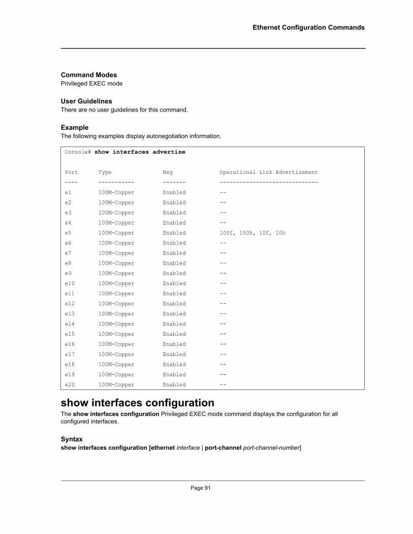
Ethernet Configuration Commands
Command Modes Privileged EXEC mode
User GuidelinesThere are no user guidelines for this command.
ExampleThe following examples display autonegotiation information.
show interfaces configurationThe show interfaces configuration Privileged EXEC mode command displays the configuration for all configured interfaces.
Syntax show interfaces configuration [ethernet interface | port-channel port-channel-number]
Console# show interfaces advertise
Port Type Neg Operational Link Advertisement
---- ----------- ------- ------------------------------
e1 100M-Copper Enabled --
e2 100M-Copper Enabled --
e3 100M-Copper Enabled --
e4 100M-Copper Enabled --
e5 100M-Copper Enabled 100f, 100h, 10f, 10h
e6 100M-Copper Enabled --
e7 100M-Copper Enabled --
e8 100M-Copper Enabled --
e9 100M-Copper Enabled --
e10 100M-Copper Enabled --
e11 100M-Copper Enabled --
e12 100M-Copper Enabled --
e13 100M-Copper Enabled --
e14 100M-Copper Enabled --
e15 100M-Copper Enabled --
e16 100M-Copper Enabled --
e17 100M-Copper Enabled --
e18 100M-Copper Enabled --
e19 100M-Copper Enabled --
e20 100M-Copper Enabled --
Page 91
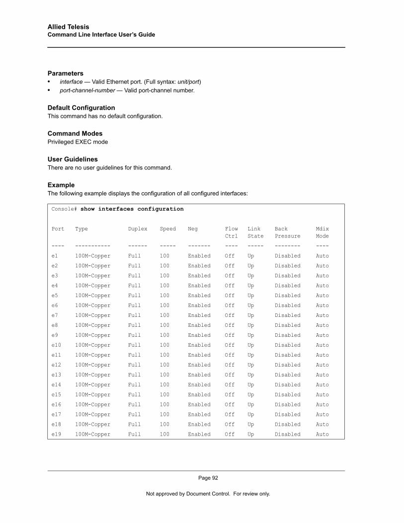
Allied Telesis Command Line Interface User’s Guide
Parameters• interface — Valid Ethernet port. (Full syntax: unit/port)• port-channel-number — Valid port-channel number.
Default ConfigurationThis command has no default configuration.
Command Modes Privileged EXEC mode
User GuidelinesThere are no user guidelines for this command.
ExampleThe following example displays the configuration of all configured interfaces:
Console# show interfaces configuration
Port Type Duplex Speed Neg Flow Ctrl
Link State
Back Pressure
Mdix Mode
---- ----------- ------ ----- ------- ---- ----- -------- ----
e1 100M-Copper Full 100 Enabled Off Up Disabled Auto
e2 100M-Copper Full 100 Enabled Off Up Disabled Auto
e3 100M-Copper Full 100 Enabled Off Up Disabled Auto
e4 100M-Copper Full 100 Enabled Off Up Disabled Auto
e5 100M-Copper Full 100 Enabled Off Up Disabled Auto
e6 100M-Copper Full 100 Enabled Off Up Disabled Auto
e7 100M-Copper Full 100 Enabled Off Up Disabled Auto
e8 100M-Copper Full 100 Enabled Off Up Disabled Auto
e9 100M-Copper Full 100 Enabled Off Up Disabled Auto
e10 100M-Copper Full 100 Enabled Off Up Disabled Auto
e11 100M-Copper Full 100 Enabled Off Up Disabled Auto
e12 100M-Copper Full 100 Enabled Off Up Disabled Auto
e13 100M-Copper Full 100 Enabled Off Up Disabled Auto
e14 100M-Copper Full 100 Enabled Off Up Disabled Auto
e15 100M-Copper Full 100 Enabled Off Up Disabled Auto
e16 100M-Copper Full 100 Enabled Off Up Disabled Auto
e17 100M-Copper Full 100 Enabled Off Up Disabled Auto
e18 100M-Copper Full 100 Enabled Off Up Disabled Auto
e19 100M-Copper Full 100 Enabled Off Up Disabled Auto
Page 92
Not approved by Document Control. For review only.
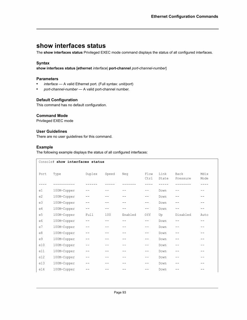
Ethernet Configuration Commands
show interfaces statusThe show interfaces status Privileged EXEC mode command displays the status of all configured interfaces.
Syntax show interfaces status [ethernet interface| port-channel port-channel-number]
Parameters• interface — A valid Ethernet port. (Full syntax: unit/port)• port-channel-number — A valid port-channel number.
Default ConfigurationThis command has no default configuration.
Command ModePrivileged EXEC mode
User GuidelinesThere are no user guidelines for this command.
ExampleThe following example displays the status of all configured interfaces:
Console# show interfaces status
Port Type Duplex Speed Neg Flow Ctrl
Link State
Back Pressure
Mdix Mode
---- ----------- ------ ----- ------- ---- ----- -------- ----
e1 100M-Copper -- -- -- -- Down -- --
e2 100M-Copper -- -- -- -- Down -- --
e3 100M-Copper -- -- -- -- Down -- --
e4 100M-Copper -- -- -- -- Down -- --
e5 100M-Copper Full 100 Enabled Off Up Disabled Auto
e6 100M-Copper -- -- -- -- Down -- --
e7 100M-Copper -- -- -- -- Down -- --
e8 100M-Copper -- -- -- -- Down -- --
e9 100M-Copper -- -- -- -- Down -- --
e10 100M-Copper -- -- -- -- Down -- --
e11 100M-Copper -- -- -- -- Down -- --
e12 100M-Copper -- -- -- -- Down -- --
e13 100M-Copper -- -- -- -- Down -- --
e14 100M-Copper -- -- -- -- Down -- --
Page 93

Allied Telesis Command Line Interface User’s Guide
show interfaces descriptionThe show interfaces description Privileged EXEC mode command displays the description for all configured interfaces.
Syntax show interfaces description [ethernet interface | port-channel port-channel-number]
Parameters• interface — Valid Ethernet port. (Full syntax: unit/port)• port-channel-number — A valid port-channel number.
Default ConfigurationThis command has no default configuration.
Command Modes Privileged EXEC mode
User GuidelinesThere are no user guidelines for this command.
ExampleThe following example displays descriptions of configured interfaces.
e15 100M-Copper -- -- -- -- Down -- --
e16 100M-Copper -- -- -- -- Down -- --
e17 100M-Copper -- -- -- -- Down -- --
e18 100M-Copper -- -- -- -- Down -- --
e19 100M-Copper -- -- -- -- Down -- --
Console# show interfaces description
Port Description
---- -----------
1/e1 lab
1/e2
1/e3
1/e4
1/e5
1/e6
ch1
ch2
Page 94
Not approved by Document Control. For review only.
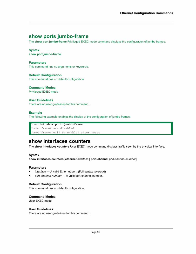
Ethernet Configuration Commands
show ports jumbo-frameThe show port jumbo-frame Privileged EXEC mode command displays the configuration of jumbo frames.
Syntaxshow port jumbo-frame
ParametersThis command has no arguments or keywords.
Default ConfigurationThis command has no default configuration.
Command Modes Privileged EXEC mode
User GuidelinesThere are no user guidelines for this command.
ExampleThe following example enables the display of the configuration of jumbo frames.
show interfaces countersThe show interfaces counters User EXEC mode command displays traffic seen by the physical interface.
Syntaxshow interfaces counters [ethernet interface | port-channel port-channel-number]
Parameters• interface — A valid Ethernet port. (Full syntax: unit/port)• port-channel-number — A valid port-channel number.
Default ConfigurationThis command has no default configuration.
Command ModesUser EXEC mode
User GuidelinesThere are no user guidelines for this command.
Console# show port jumbo-frameJumbo frames are disabled
Jumbo frames will be enabled after reset
Page 95
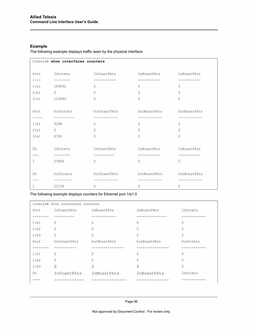
Allied Telesis Command Line Interface User’s Guide
Example The following example displays traffic seen by the physical interface:
The following example displays counters for Ethernet port 1/e1.0
Console# show interfaces counters
Port InOctets InUcastPkts InMcastPkts InBcastPkts
---- -------- ----------- ----------- -----------
1/e1 183892 0 0 0
2/e1 0 0 0 0
3/e1 123899 0 0 0
Port OutOctets OutUcastPkts OutMcastPkts OutBcastPkts
----- ---------- ------------ ------------ ------------
1/e1 9188 0 0 0
2/e1 0 0 0 0
3/e1 8789 0 0 0
Ch InOctets InUcastPkts InMcastPkts InBcastPkts
--- -------- ---------- ----------- -----------
1 27889 0 0 0
Ch OutOctets OutUcastPkts OutMcastPkts OutBcastPkts
--- --------- ------------ ------------ ------------
1 23739 0 0 0
console# show interfaces counters
Port InUcastPkts InMcastPkts InBcastPkts InOctets
-------- ---------- ------------ --------------- ------------
1/e1 0 0 0 0
1/e2 0 0 0 0
1/e3 0 0 0 0
Port OutUcastPkts OutMcastPkts OutBcastPkts OutOctets
-------- ----------- ---------------- ---------------- ------------
1/e1 0 0 0 0
1/e2 0 0 0 0
1/e3 0 0 0 0
Ch InUcastPkts InMcastPkts InBcastPkts InOctets
---- ------------ -------------- ------------- ------------
Page 96
Not approved by Document Control. For review only.
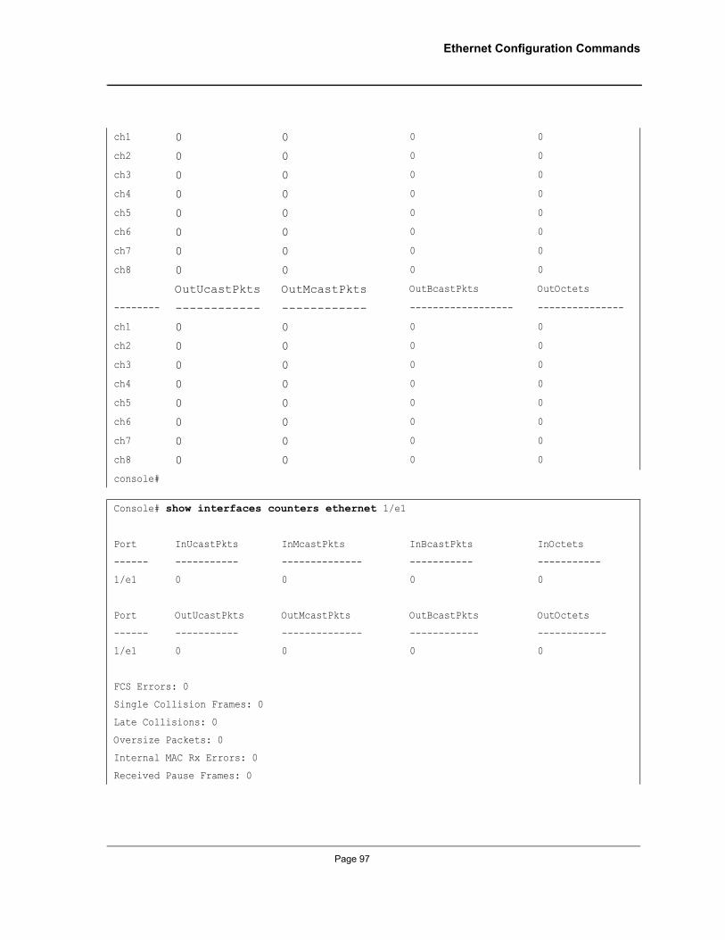
Ethernet Configuration Commands
ch1 0 0 0 0
ch2 0 0 0 0
ch3 0 0 0 0
ch4 0 0 0 0
ch5 0 0 0 0
ch6 0 0 0 0
ch7 0 0 0 0
ch8 0 0 0 0
OutUcastPkts OutMcastPkts OutBcastPkts OutOctets
-------- ------------ ------------ ------------------ ---------------
ch1 0 0 0 0
ch2 0 0 0 0
ch3 0 0 0 0
ch4 0 0 0 0
ch5 0 0 0 0
ch6 0 0 0 0
ch7 0 0 0 0
ch8 0 0 0 0
console#
Console# show interfaces counters ethernet 1/e1
Port InUcastPkts InMcastPkts InBcastPkts InOctets
------ ----------- -------------- ----------- -----------
1/e1 0 0 0 0
Port OutUcastPkts OutMcastPkts OutBcastPkts OutOctets
------ ----------- -------------- ------------ ------------
1/e1 0 0 0 0
FCS Errors: 0
Single Collision Frames: 0
Late Collisions: 0
Oversize Packets: 0
Internal MAC Rx Errors: 0
Received Pause Frames: 0
Page 97
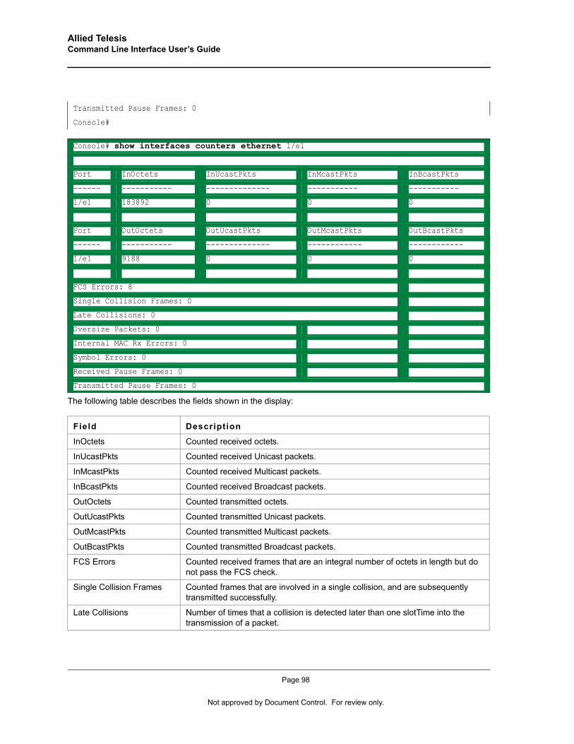
Allied Telesis Command Line Interface User’s Guide
The following table describes the fields shown in the display:
Transmitted Pause Frames: 0
Console#
Console# show interfaces counters ethernet 1/e1
Port InOctets InUcastPkts InMcastPkts InBcastPkts
------ ----------- -------------- ----------- -----------
1/e1 183892 0 0 0
Port OutOctets OutUcastPkts OutMcastPkts OutBcastPkts
------ ----------- -------------- ------------ ------------
1/e1 9188 0 0 0
FCS Errors: 8
Single Collision Frames: 0
Late Collisions: 0
Oversize Packets: 0
Internal MAC Rx Errors: 0
Symbol Errors: 0
Received Pause Frames: 0
Transmitted Pause Frames: 0
Field Description
InOctets Counted received octets.
InUcastPkts Counted received Unicast packets.
InMcastPkts Counted received Multicast packets.
InBcastPkts Counted received Broadcast packets.
OutOctets Counted transmitted octets.
OutUcastPkts Counted transmitted Unicast packets.
OutMcastPkts Counted transmitted Multicast packets.
OutBcastPkts Counted transmitted Broadcast packets.
FCS Errors Counted received frames that are an integral number of octets in length but do not pass the FCS check.
Single Collision Frames Counted frames that are involved in a single collision, and are subsequently transmitted successfully.
Late Collisions Number of times that a collision is detected later than one slotTime into the transmission of a packet.
Page 98
Not approved by Document Control. For review only.
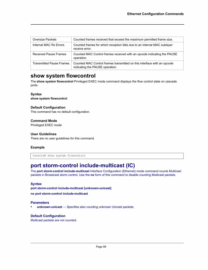
Ethernet Configuration Commands
show system flowcontrolThe show system flowcontrol Privileged EXEC mode command displays the flow control state on cascade ports.
Syntaxshow system flowcontrol
Default ConfigurationThis command has no default configuration.
Command ModePrivileged EXEC mode
User GuidelinesThere are no user guidelines for this command.
Example
port storm-control include-multicast (IC)The port storm-control include-multicast Interface Configuration (Ethernet) mode command counts Multicast packets in Broadcast storm control. Use the no form of this command to disable counting Multicast packets.
Syntaxport storm-control include-multicast [unknown-unicast]
no port storm-control include-multicast
Parameters• unknown-unicast — Specifies also counting unknown Unicast packets.
Default ConfigurationMulticast packets are not counted.
Oversize Packets Counted frames received that exceed the maximum permitted frame size.
Internal MAC Rx Errors Counted frames for which reception fails due to an internal MAC sublayer receive error.
Received Pause Frames Counted MAC Control frames received with an opcode indicating the PAUSE operation.
Transmitted Pause Frames Counted MAC Control frames transmitted on this interface with an opcode indicating the PAUSE operation.
Console# show system flowcontrol
Page 99
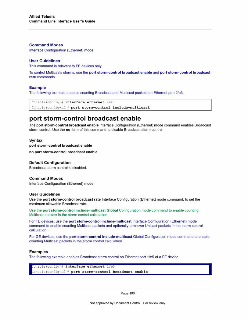
Allied Telesis Command Line Interface User’s Guide
Command Modes Interface Configuration (Ethernet) mode
User GuidelinesThis command is relevant to FE devices only.
To control Multicasts storms, use the port storm-control broadcast enable and port storm-control broadcast rate commands.
Example The following example enables counting Broadcast and Multicast packets on Ethernet port 2/e3.
port storm-control broadcast enableThe port storm-control broadcast enable Interface Configuration (Ethernet) mode command enables Broadcast storm control. Use the no form of this command to disable Broadcast storm control.
Syntaxport storm-control broadcast enable
no port storm-control broadcast enable
Default ConfigurationBroadcast storm control is disabled.
Command Modes Interface Configuration (Ethernet) mode
User GuidelinesUse the port storm-control broadcast rate Interface Configuration (Ethernet) mode command, to set the maximum allowable Broadcast rate.
Use the port storm-control include-multicast Global Configuration mode command to enable counting Multicast packets in the storm control calculation.
For FE devices, use the port storm-control include-multicast Interface Configuration (Ethernet) mode command to enable counting Multicast packets and optionally unknown Unicast packets in the storm control calculation.
For GE devices, use the port storm-control include-multicast Global Configuration mode command to enable counting Multicast packets in the storm control calculation.
Examples The following example enables Broadcast storm control on Ethernet port 1/e5 of a FE device.
Console(config)# interface ethernet 2/e3Console(config-if)# port storm-control include-multicast
Console(config)# interface ethernet 1/e5Console(config-if)# port storm-control broadcast enable
Page 100
Not approved by Document Control. For review only.
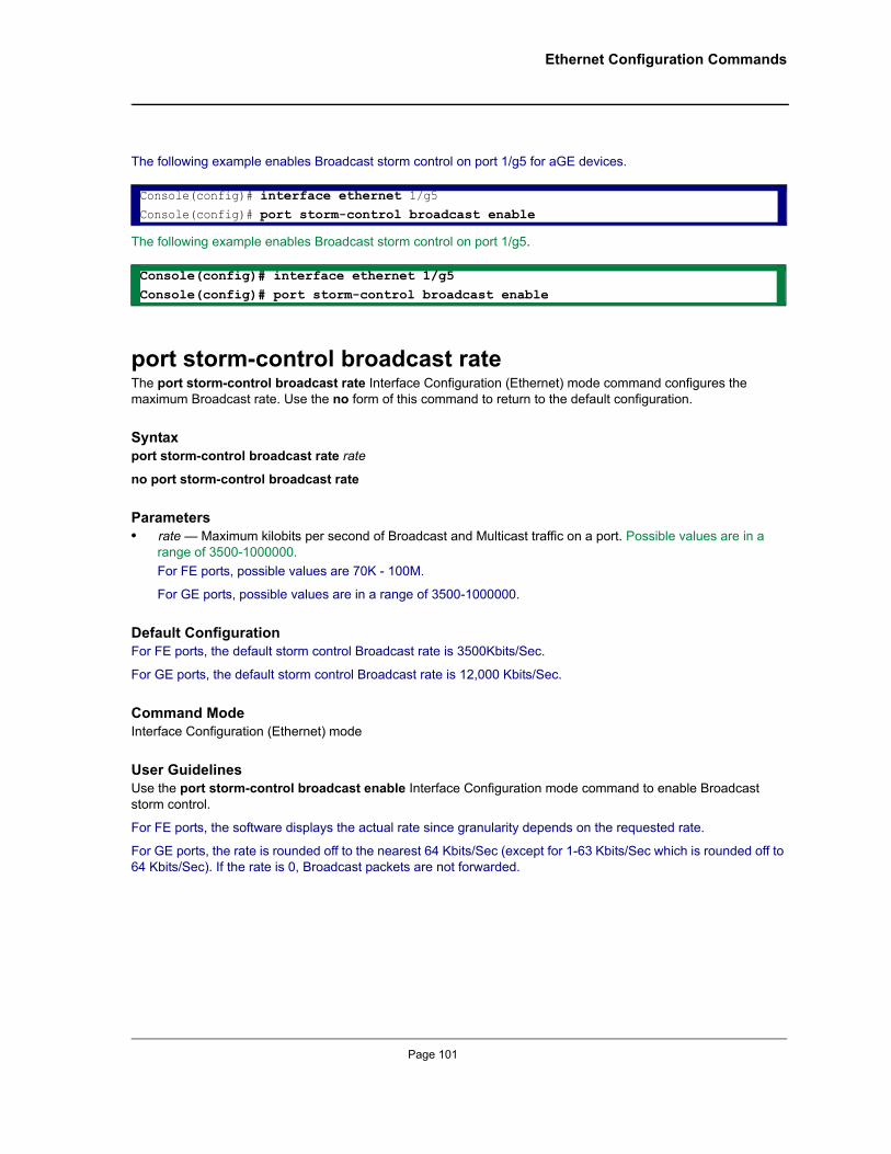
Ethernet Configuration Commands
The following example enables Broadcast storm control on port 1/g5 for aGE devices.
The following example enables Broadcast storm control on port 1/g5.
port storm-control broadcast rateThe port storm-control broadcast rate Interface Configuration (Ethernet) mode command configures the maximum Broadcast rate. Use the no form of this command to return to the default configuration.
Syntaxport storm-control broadcast rate rate
no port storm-control broadcast rate
Parameters• rate — Maximum kilobits per second of Broadcast and Multicast traffic on a port. Possible values are in a
range of 3500-1000000.For FE ports, possible values are 70K - 100M.
For GE ports, possible values are in a range of 3500-1000000.
Default ConfigurationFor FE ports, the default storm control Broadcast rate is 3500Kbits/Sec.
For GE ports, the default storm control Broadcast rate is 12,000 Kbits/Sec.
Command ModeInterface Configuration (Ethernet) mode
User GuidelinesUse the port storm-control broadcast enable Interface Configuration mode command to enable Broadcast storm control.
For FE ports, the software displays the actual rate since granularity depends on the requested rate.
For GE ports, the rate is rounded off to the nearest 64 Kbits/Sec (except for 1-63 Kbits/Sec which is rounded off to 64 Kbits/Sec). If the rate is 0, Broadcast packets are not forwarded.
Console(config)# interface ethernet 1/g5Console(config)# port storm-control broadcast enable
Console(config)# interface ethernet 1/g5Console(config)# port storm-control broadcast enable
Page 101
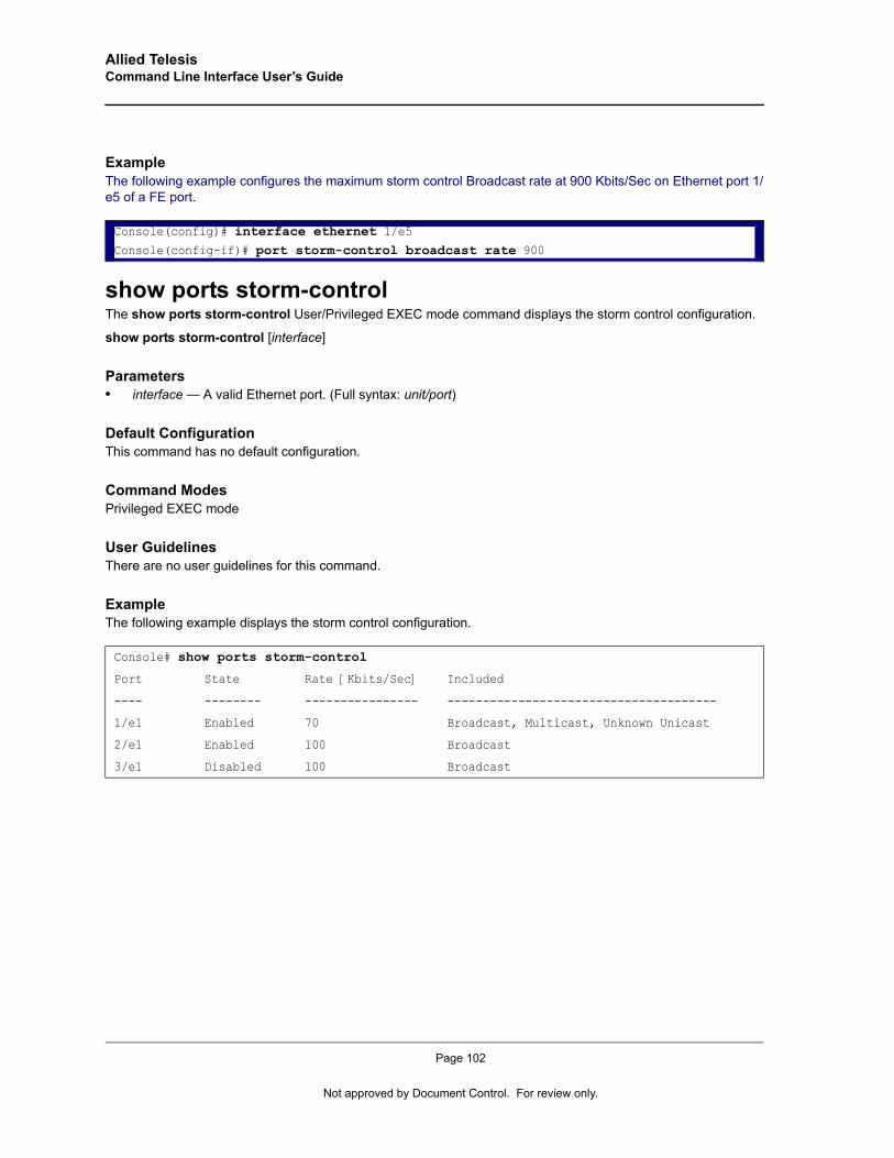
Allied Telesis Command Line Interface User’s Guide
Example The following example configures the maximum storm control Broadcast rate at 900 Kbits/Sec on Ethernet port 1/e5 of a FE port.
show ports storm-controlThe show ports storm-control User/Privileged EXEC mode command displays the storm control configuration.
show ports storm-control [interface]
Parameters• interface — A valid Ethernet port. (Full syntax: unit/port)
Default ConfigurationThis command has no default configuration.
Command ModesPrivileged EXEC mode
User GuidelinesThere are no user guidelines for this command.
ExampleThe following example displays the storm control configuration.
Console(config)# interface ethernet 1/e5Console(config-if)# port storm-control broadcast rate 900
Console# show ports storm-control
Port State Rate [Kbits/Sec] Included
---- -------- ---------------- --------------------------------------
1/e1 Enabled 70 Broadcast, Multicast, Unknown Unicast
2/e1 Enabled 100 Broadcast
3/e1 Disabled 100 Broadcast
Page 102
Not approved by Document Control. For review only.
GVRP Commands
Chapter 10.GVRP Commands
gvrp enable (Global)GARP VLAN Registration Protocol (GVRP) is an industry-standard protocol designed to propagate VLAN information from device to device. With GVRP, a single device is manually configured with all desired VLANs for the network, and all other devices on the network learn these VLANs dynamically.
The gvrp enable Global Configuration mode command enables GVRP globally. Use the no form of this command to disable GVRP on the device.
Syntaxgvrp enable
no gvrp enable
Default ConfigurationGVRP is globally disabled.
Command ModeGlobal Configuration mode
User GuidelinesThere are no user guidelines for this command.
ExampleThe following example enables GVRP globally on the device.
gvrp enable (Interface)The gvrp enable Interface Configuration (Ethernet, port-channel) mode command enables GVRP on an interface. Use the no form of this command to disable GVRP on an interface.
Syntaxgvrp enable
no gvrp enable
Default ConfigurationGVRP is disabled on all interfaces.
Command ModeInterface Configuration (Ethernet, port-channel) mode
Console(config)# gvrp enable
Page 103
Allied Telesis Command Line Interface User’s Guide
User GuidelinesAn access port does not dynamically join a VLAN because it is always a member in only one VLAN.
Membership in an untagged VLAN is propagated in the same way as in a tagged VLAN. That is, the PVID is manually defined as the untagged VLAN VID.
ExampleThe following example enables GVRP on Ethernet port 1/e6.
garp timerThe garp timer Interface Configuration (Ethernet, Port channel) mode command adjusts the values of the join, leave and leaveall timers of GARP applications. Use the no form of this command to return to the default configuration.
Syntaxgarp timer {join | leave | leaveall} timer_value
no garp timer
Parameters• {join | leave | leaveall} — Indicates the type of timer.• timer_value — Timer values in milliseconds in multiples of 10. (Range: 10-2147483647)
Default ConfigurationFollowing are the default timer values:
• Join timer — 200 milliseconds• Leave timer — 600 milliseconds• Leavall timer — 10000 milliseconds
Command ModeInterface configuration (Ethernet, port-channel) mode
User GuidelinesThe following relationship must be maintained between the timers:
Leave time must be greater than or equal to three times the join time.
Leave-all time must be greater than the leave time.
Set the same GARP timer values on all Layer 2-connected devices. If the GARP timers are set differently on Layer 2-connected devices, the GARP application will not operate successfully.
Console(config)# interface ethernet 1/e6Console(config-if)# gvrp enable
Page 104
Not approved by Document Control. For review only.
GVRP Commands
ExampleThe following example sets the leave timer for Ethernet port 1/e6 to 900 milliseconds.
gvrp vlan-creation-forbidThe gvrp vlan-creation-forbid Interface Configuration (Ethernet, port-channel) mode command disables dynamic VLAN creation or modification. Use the no form of this command to enable dynamic VLAN creation or modification.
Syntaxgvrp vlan-creation-forbid
no gvrp vlan-creation-forbid
Default ConfigurationDynamic VLAN creation or modification is enabled.
Command ModeInterface Configuration (Ethernet, port-channel) mode
User GuidelinesThis command forbids dynamic VLAN creation from the interface. The creation or modification of dynamic VLAN registration entries as a result of the GVRP exchanges on an interface are restricted only to those VLANs for which static VLAN registration exists.
ExampleThe following example disables dynamic VLAN creation on Ethernet port 1/e6.
gvrp registration-forbidThe gvrp registration-forbid Interface Configuration (Ethernet, port-channel) mode command deregisters all dynamic VLANs on a port and prevents VLAN creation or registration on the port. Use the no form of this command to allow dynamic registration of VLANs on a port.
Syntaxgvrp registration-forbid
no gvrp registration-forbid
Default ConfigurationDynamic registration of VLANs on the port is allowed.
Console(config)# interface ethernet 1/e6Console(config-if)# garp timer leave 900
Console(config)# interface ethernet 1/e6Console(config-if)# gvrp vlan-creation-forbid
Page 105
Allied Telesis Command Line Interface User’s Guide
Command ModeInterface Configuration (Ethernet, port-channel) mode
User GuidelinesThere are no user guidelines for this command.
ExampleThe following example forbids dynamic registration of VLANs on Ethernet port 1/e6.
clear gvrp statisticsThe clear gvrp statistics Privileged EXEC mode command clears all GVRP statistical information.
Syntaxclear gvrp statistics [ethernet interface | port-channel port-channel-number]
Parameters• interface — A valid Ethernet port. (Full syntax: unit/port)• port-channel-number — A valid port-channel number.
Default ConfigurationThis command has no default configuration.
Command ModePrivileged EXEC mode
User GuidelinesThere are no user guidelines for this command.
ExampleThe following example clears all GVRP statistical information on Ethernet port 1/e6.
show gvrp configurationThe show gvrp configuration User EXEC mode command displays GVRP configuration information, including timer values, whether GVRP and dynamic VLAN creation is enabled, and which ports are running GVRP.
Syntaxshow gvrp configuration [ethernet interface | port-channel port-channel-number]
Console(config)# interface ethernet 1/e6Console(config-if)# gvrp registration-forbid
Console# clear gvrp statistics ethernet 1/e6
Page 106
Not approved by Document Control. For review only.
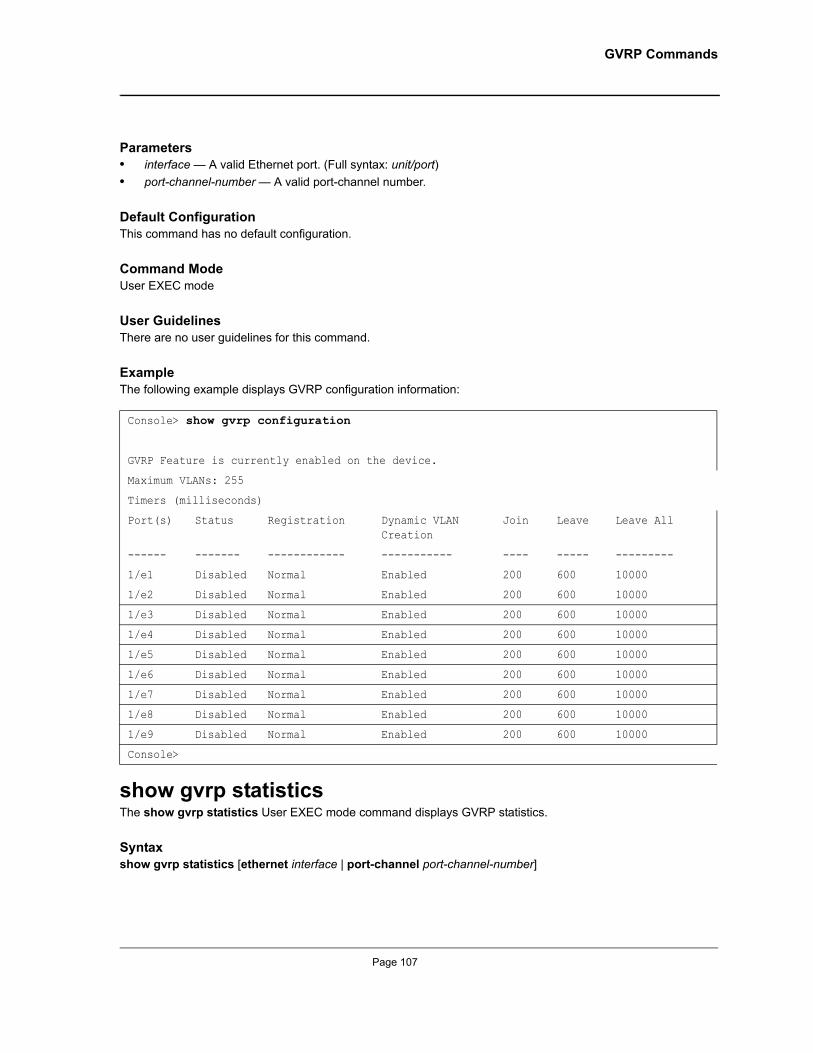
GVRP Commands
Parameters• interface — A valid Ethernet port. (Full syntax: unit/port)• port-channel-number — A valid port-channel number.
Default ConfigurationThis command has no default configuration.
Command ModeUser EXEC mode
User GuidelinesThere are no user guidelines for this command.
ExampleThe following example displays GVRP configuration information:
show gvrp statisticsThe show gvrp statistics User EXEC mode command displays GVRP statistics.
Syntaxshow gvrp statistics [ethernet interface | port-channel port-channel-number]
Console> show gvrp configuration
GVRP Feature is currently enabled on the device.
Maximum VLANs: 255
Timers (milliseconds)
Port(s) Status Registration Dynamic VLAN Creation
Join Leave Leave All
------ ------- ------------ ----------- ---- ----- ---------
1/e1 Disabled Normal Enabled 200 600 10000
1/e2 Disabled Normal Enabled 200 600 10000
1/e3 Disabled Normal Enabled 200 600 10000
1/e4 Disabled Normal Enabled 200 600 10000
1/e5 Disabled Normal Enabled 200 600 10000
1/e6 Disabled Normal Enabled 200 600 10000
1/e7 Disabled Normal Enabled 200 600 10000
1/e8 Disabled Normal Enabled 200 600 10000
1/e9 Disabled Normal Enabled 200 600 10000
Console>
Page 107
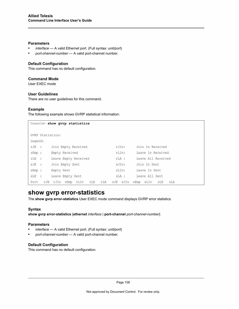
Allied Telesis Command Line Interface User’s Guide
Parameters• interface — A valid Ethernet port. (Full syntax: unit/port)• port-channel-number — A valid port-channel number.
Default ConfigurationThis command has no default configuration.
Command ModeUser EXEC mode
User GuidelinesThere are no user guidelines for this command.
ExampleThe following example shows GVRP statistical information:
show gvrp error-statisticsThe show gvrp error-statistics User EXEC mode command displays GVRP error statistics.
Syntaxshow gvrp error-statistics [ethernet interface | port-channel port-channel-number]
Parameters• interface — A valid Ethernet port. (Full syntax: unit/port)• port-channel-number — A valid port-channel number.
Default ConfigurationThis command has no default configuration.
Console> show gvrp statistics
GVRP Statistics:
Legend:
rJE : Join Empty Received rJIn: Join In Received
rEmp : Empty Received rLIn: Leave In Received
rLE : Leave Empty Received rLA : Leave All Received
sJE : Join Empty Sent sJIn: Join In Sent
sEmp : Empty Sent sLIn: Leave In Sent
sLE : Leave Empty Sent sLA : Leave All Sent
Port rJE rJIn rEmp rLIn rLE rLA sJE sJIn sEmp sLIn sLE sLA
Page 108
Not approved by Document Control. For review only.
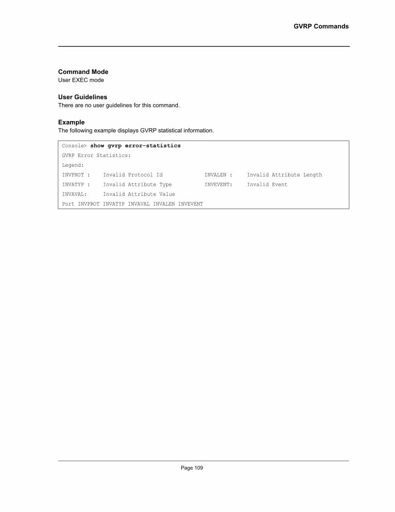
GVRP Commands
Command ModeUser EXEC mode
User GuidelinesThere are no user guidelines for this command.
ExampleThe following example displays GVRP statistical information.
Console> show gvrp error-statistics
GVRP Error Statistics:
Legend:
INVPROT : Invalid Protocol Id INVALEN : Invalid Attribute Length
INVATYP : Invalid Attribute Type INVEVENT: Invalid Event
INVAVAL: Invalid Attribute Value
Port INVPROT INVATYP INVAVAL INVALEN INVEVENT
Page 109
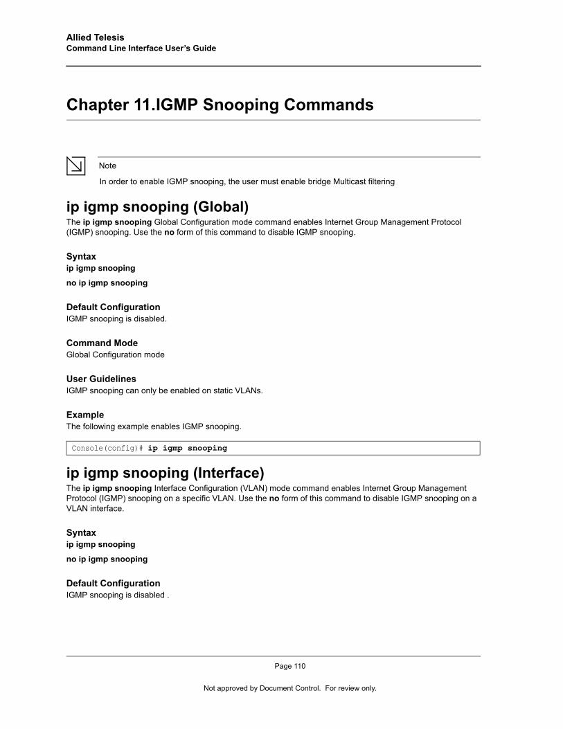
Allied Telesis Command Line Interface User’s Guide
Chapter 11.IGMP Snooping Commands
Note
In order to enable IGMP snooping, the user must enable bridge Multicast filtering
ip igmp snooping (Global)The ip igmp snooping Global Configuration mode command enables Internet Group Management Protocol (IGMP) snooping. Use the no form of this command to disable IGMP snooping.
Syntaxip igmp snooping
no ip igmp snooping
Default ConfigurationIGMP snooping is disabled.
Command ModeGlobal Configuration mode
User GuidelinesIGMP snooping can only be enabled on static VLANs.
ExampleThe following example enables IGMP snooping.
ip igmp snooping (Interface)The ip igmp snooping Interface Configuration (VLAN) mode command enables Internet Group Management Protocol (IGMP) snooping on a specific VLAN. Use the no form of this command to disable IGMP snooping on a VLAN interface.
Syntaxip igmp snooping
no ip igmp snooping
Default ConfigurationIGMP snooping is disabled .
Console(config)# ip igmp snooping
Page 110
Not approved by Document Control. For review only.

IGMP Snooping Commands
Command ModeInterface Configuration (VLAN) mode
User GuidelinesIGMP snooping can only be enabled on static VLANs.
ExampleThe following example enables IGMP snooping on VLAN 2.
ip igmp snooping mrouter learn-pim-dvmrpThe ip igmp snooping mrouter learn-pim-dvmrp Interface Configuration (VLAN) mode command enables automatic learning of Multicast device ports in the context of a specific VLAN. Use the no form of this command to remove automatic learning of Multicast device ports.
Syntaxip igmp snooping mrouter learn-pim-dvmrp
no ip igmp snooping mrouter learn-pim-dvmrp
Default ConfigurationAutomatic learning of Multicast device ports is enabled.
Command ModeInterface Configuration (VLAN) mode
User GuidelinesMulticast device ports can be configured statically using the bridge multicast forward-all Interface Configuration (VLAN) mode command.
ExampleThe following example enables automatic learning of Multicast device ports on VLAN 2.
Console(config)# interface vlan 2Console(config-if)# ip igmp snooping
Console(config) # interface vlan 2Console(config-if)# ip igmp snooping mrouter learn-pim-dvmrp
Page 111

Allied Telesis Command Line Interface User’s Guide
ip igmp snooping host-time-outThe ip igmp snooping host-time-out Interface Configuration (VLAN) mode command configures the host-time-out. If an IGMP report for a Multicast group was not received for a host-time-out period from a specific port, this port is deleted from the member list of that Multicast group. Use the no form of this command to return to the default configuration.
Syntaxip igmp snooping host-time-out time-out
no ip igmp snooping host-time-out
Parameters• time-out — Host timeout in seconds. (Range: 60 – 2147483647)
Default ConfigurationThe default host-time-out is 260 seconds.
Command ModeInterface Configuration (VLAN) mode
User GuidelinesThe timeout should be at least greater than 2*query_interval+max_response_time of the IGMP router.
ExampleThe following example configures the host timeout to 300 seconds.
ip igmp snooping querier enableThe ip igmp snooping querier enable Interface Configuration mode command enables Internet Group Management Protocol (IGMP) querier on a specific VLAN. Use the no form of this command to disable IGMP querier on a VLAN interface.
Syntaxip igmp snooping querier enable
no ip igmp snooping querier enable
ParametersThis command has no arguments or keywords
Default ConfigurationDisabled.
Console(config)# interface vlan 2Console(config-if)# ip igmp snooping host-time-out 300
Page 112
Not approved by Document Control. For review only.
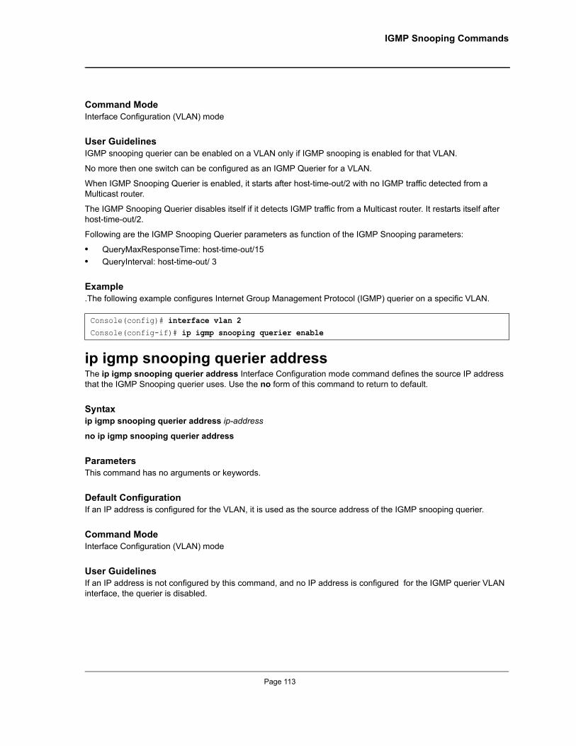
IGMP Snooping Commands
Command ModeInterface Configuration (VLAN) mode
User GuidelinesIGMP snooping querier can be enabled on a VLAN only if IGMP snooping is enabled for that VLAN.
No more then one switch can be configured as an IGMP Querier for a VLAN.
When IGMP Snooping Querier is enabled, it starts after host-time-out/2 with no IGMP traffic detected from a Multicast router.
The IGMP Snooping Querier disables itself if it detects IGMP traffic from a Multicast router. It restarts itself after host-time-out/2.
Following are the IGMP Snooping Querier parameters as function of the IGMP Snooping parameters:
• QueryMaxResponseTime: host-time-out/15• QueryInterval: host-time-out/ 3
Example.The following example configures Internet Group Management Protocol (IGMP) querier on a specific VLAN.
ip igmp snooping querier addressThe ip igmp snooping querier address Interface Configuration mode command defines the source IP address that the IGMP Snooping querier uses. Use the no form of this command to return to default.
Syntaxip igmp snooping querier address ip-address
no ip igmp snooping querier address
ParametersThis command has no arguments or keywords.
Default ConfigurationIf an IP address is configured for the VLAN, it is used as the source address of the IGMP snooping querier.
Command ModeInterface Configuration (VLAN) mode
User GuidelinesIf an IP address is not configured by this command, and no IP address is configured for the IGMP querier VLAN interface, the querier is disabled.
Console(config)# interface vlan 2Console(config-if)# ip igmp snooping querier enable
Page 113

Allied Telesis Command Line Interface User’s Guide
Example.The following example configures the source IP address that the IGMP Snooping querier uses.
ip igmp snooping querier versionThe ip igmp snooping querier version Interface Configuration mode command configures the IGMP version of an IGMP querier on a specific VLAN. Use the no form of this command to return to default.
Syntaxip igmp snooping querier version {2 | 3}
no ip igmp snooping querier version
Parameters• 2 — Specifies that the IGMP version is IGMPv2.• 3 — Specifies that the IGMP version is IGMPv3.
Default ConfigurationIGMPv3
Command ModeInterface Configuration (VLAN) mode
User GuidelinesIf the IGMP querier is configured to IGMPv3, the querier trys to work in IGMPv3. In case the hosts do not support IGMPv3, the querier version is downgraded.
If the IGMP querier is configured to IGMPv2, the querier trys to work in IGMPv2. It can be downgraded automatically to IGMPv1, but never upgraded automatically to IGMPv3.
Example.The following example configures the IGMP version of an IGMP querier on a specific VLAN.
ip igmp snooping mrouter-time-outThe ip igmp snooping mrouter-time-out Interface Configuration (VLAN) mode command configures the mrouter-time-out. The ip igmp snooping mrouter-time-out Interface Configuration (VLAN) mode command is used for setting the aging-out time after Multicast device ports are automatically learned. Use the no form of this command to return to the default configuration.
Syntaxip igmp snooping mrouter-time-out time-out
Console(config)# interface vlan 2Console(config-if)# ip igmp snooping querier address 192.168.1.220
Console(config)# interface vlan 2Console(config-if)# ip igmp snooping querier version 2
Page 114
Not approved by Document Control. For review only.
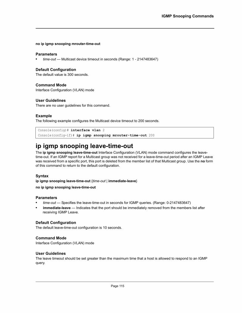
IGMP Snooping Commands
no ip igmp snooping mrouter-time-out
Parameters• time-out — Multicast device timeout in seconds (Range: 1 - 2147483647)
Default ConfigurationThe default value is 300 seconds.
Command ModeInterface Configuration (VLAN) mode
User GuidelinesThere are no user guidelines for this command.
ExampleThe following example configures the Multicast device timeout to 200 seconds.
ip igmp snooping leave-time-outThe ip igmp snooping leave-time-out Interface Configuration (VLAN) mode command configures the leave-time-out. If an IGMP report for a Multicast group was not received for a leave-time-out period after an IGMP Leave was received from a specific port, this port is deleted from the member list of that Multicast group. Use the no form of this command to return to the default configuration.
Syntaxip igmp snooping leave-time-out {time-out | immediate-leave}
no ip igmp snooping leave-time-out
Parameters• time-out — Specifies the leave-time-out in seconds for IGMP queries. (Range: 0-2147483647)• immediate-leave — Indicates that the port should be immediately removed from the members list after
receiving IGMP Leave.
Default ConfigurationThe default leave-time-out configuration is 10 seconds.
Command ModeInterface Configuration (VLAN) mode
User GuidelinesThe leave timeout should be set greater than the maximum time that a host is allowed to respond to an IGMP query.
Console(config)# interface vlan 2Console(config-if)# ip igmp snooping mrouter-time-out 200
Page 115
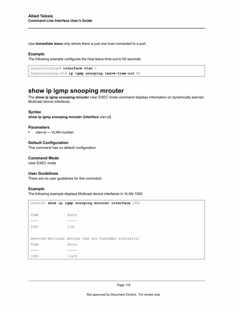
Allied Telesis Command Line Interface User’s Guide
Use immediate leave only where there is just one host connected to a port.
ExampleThe following example configures the host leave-time-out to 60 seconds.
show ip igmp snooping mrouterThe show ip igmp snooping mrouter User EXEC mode command displays information on dynamically learned Multicast device interfaces.
Syntaxshow ip igmp snooping mrouter [interface vlan-id]
Parameters• vlan-id — VLAN number.
Default ConfigurationThis command has no default configuration.
Command ModeUser EXEC mode
User GuidelinesThere are no user guidelines for this command.
ExampleThe following example displays Multicast device interfaces in VLAN 1000.
Console(config)# interface vlan 2Console(config-if)# ip igmp snooping leave-time-out 60
Console> show ip igmp snooping mrouter interface 1000
VLAN Ports
---- -----
1000 1/e1
Detected Multicast devices that are forbidden statically:
VLAN Ports
---- -----
1000 1/e19
Page 116
Not approved by Document Control. For review only.
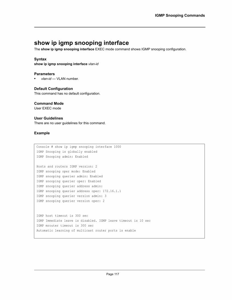
IGMP Snooping Commands
show ip igmp snooping interfaceThe show ip igmp snooping interface EXEC mode command shows IGMP snooping configuration.
Syntaxshow ip igmp snooping interface vlan-id
Parameters• vlan-id — VLAN number.
Default ConfigurationThis command has no default configuration.
Command ModeUser EXEC mode
User GuidelinesThere are no user guidelines for this command.
Example
Console # show ip igmp snooping interface 1000
IGMP Snooping is globally enabled
IGMP Snooping admin: Enabled
Hosts and routers IGMP version: 2
IGMP snooping oper mode: EnabledIGMP snooping querier admin: Enabled
IGMP snooping querier oper: Enabled
IGMP snooping querier address admin:
IGMP snooping querier address oper: 172.16.1.1IGMP snooping querier version admin: 3
IGMP snooping querier version oper: 2
IGMP host timeout is 300 sec
IGMP Immediate leave is disabled. IGMP leave timeout is 10 secIGMP mrouter timeout is 300 sec
Automatic learning of multicast router ports is enable
Page 117
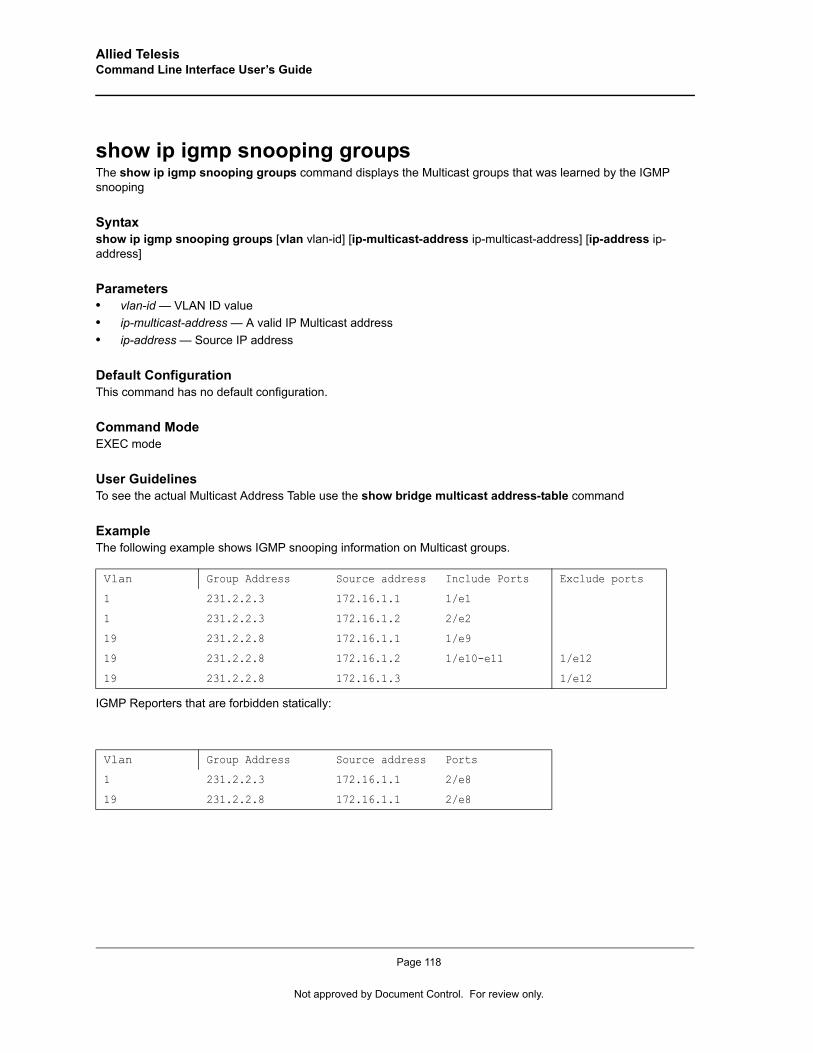
Allied Telesis Command Line Interface User’s Guide
show ip igmp snooping groupsThe show ip igmp snooping groups command displays the Multicast groups that was learned by the IGMP snooping
Syntaxshow ip igmp snooping groups [vlan vlan-id] [ip-multicast-address ip-multicast-address] [ip-address ip-address]
Parameters• vlan-id — VLAN ID value• ip-multicast-address — A valid IP Multicast address• ip-address — Source IP address
Default ConfigurationThis command has no default configuration.
Command ModeEXEC mode
User GuidelinesTo see the actual Multicast Address Table use the show bridge multicast address-table command
ExampleThe following example shows IGMP snooping information on Multicast groups.
IGMP Reporters that are forbidden statically:
Vlan Group Address Source address Include Ports Exclude ports
1 231.2.2.3 172.16.1.1 1/e1
1 231.2.2.3 172.16.1.2 2/e2
19 231.2.2.8 172.16.1.1 1/e9
19 231.2.2.8 172.16.1.2 1/e10-e11 1/e12
19 231.2.2.8 172.16.1.3 1/e12
Vlan Group Address Source address Ports
1 231.2.2.3 172.16.1.1 2/e8
19 231.2.2.8 172.16.1.1 2/e8
Page 118
Not approved by Document Control. For review only.

IP Addressing Commands
Chapter 12.IP Addressing Commands
ip addressThe ip address Interface Configuration (Ethernet, VLAN, port-channel) mode command sets an IP address. Use the no form of this command to remove an IP address.
Syntaxip address ip-address {mask | prefix-length}
no ip address [ip-address]
Parameters• ip-address —Valid IP address• mask — Valid network mask of the IP address. • prefix-length — Specifies the number of bits that comprise the IP address prefix. The prefix length must be
preceded by a forward slash (/). (Range: 8 -30)
Default ConfigurationNo IP address is defined for interfaces.
Command ModeInterface Configuration (VLAN) mode
User GuidelinesA single IP address can be defined. The IP address can be defined only on the Management VLAN.
ExampleThe following example configures VLAN 1 with IP address 131.108.1.27 and subnet mask 255.255.255.0.
ip address dhcpThe ip address dhcp Interface Configuration (Ethernet, VLAN, port-channel) mode command acquires an IP address for an Ethernet interface from the Dynamic Host Configuration Protocol (DHCP) server. Use the no form of this command to deconfigure an acquired IP address.
Syntaxip address dhcp [hostname host-name]
no ip address dhcp
Console(config)# interface vlan 1Console(config-if)# ip address 131.108.1.27 255.255.255.0
Page 119
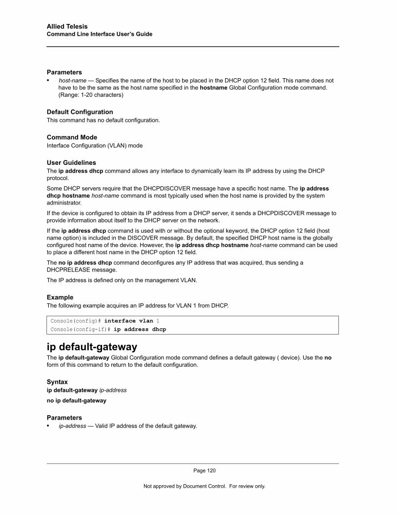
Allied Telesis Command Line Interface User’s Guide
Parameters• host-name — Specifies the name of the host to be placed in the DHCP option 12 field. This name does not
have to be the same as the host name specified in the hostname Global Configuration mode command. (Range: 1-20 characters)
Default ConfigurationThis command has no default configuration.
Command ModeInterface Configuration (VLAN) mode
User GuidelinesThe ip address dhcp command allows any interface to dynamically learn its IP address by using the DHCP protocol.
Some DHCP servers require that the DHCPDISCOVER message have a specific host name. The ip address dhcp hostname host-name command is most typically used when the host name is provided by the system administrator.
If the device is configured to obtain its IP address from a DHCP server, it sends a DHCPDISCOVER message to provide information about itself to the DHCP server on the network.
If the ip address dhcp command is used with or without the optional keyword, the DHCP option 12 field (host name option) is included in the DISCOVER message. By default, the specified DHCP host name is the globally configured host name of the device. However, the ip address dhcp hostname host-name command can be used to place a different host name in the DHCP option 12 field.
The no ip address dhcp command deconfigures any IP address that was acquired, thus sending a DHCPRELEASE message.
The IP address is defined only on the management VLAN.
ExampleThe following example acquires an IP address for VLAN 1 from DHCP.
ip default-gatewayThe ip default-gateway Global Configuration mode command defines a default gateway ( device). Use the no form of this command to return to the default configuration.
Syntaxip default-gateway ip-address
no ip default-gateway
Parameters• ip-address — Valid IP address of the default gateway.
Console(config)# interface vlan 1Console(config-if)# ip address dhcp
Page 120
Not approved by Document Control. For review only.
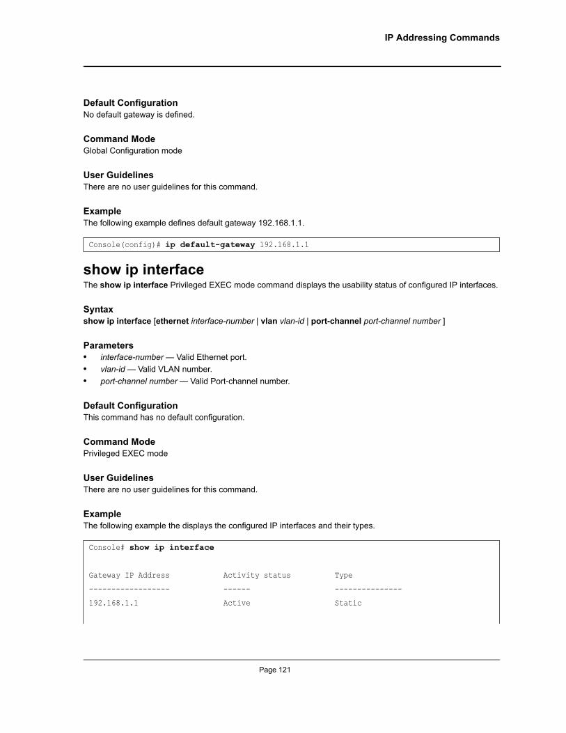
IP Addressing Commands
Default ConfigurationNo default gateway is defined.
Command ModeGlobal Configuration mode
User Guidelines There are no user guidelines for this command.
ExampleThe following example defines default gateway 192.168.1.1.
show ip interfaceThe show ip interface Privileged EXEC mode command displays the usability status of configured IP interfaces.
Syntaxshow ip interface [ethernet interface-number | vlan vlan-id | port-channel port-channel number ]
Parameters• interface-number — Valid Ethernet port.• vlan-id — Valid VLAN number.• port-channel number — Valid Port-channel number.
Default ConfigurationThis command has no default configuration.
Command ModePrivileged EXEC mode
User GuidelinesThere are no user guidelines for this command.
ExampleThe following example the displays the configured IP interfaces and their types.
Console(config)# ip default-gateway 192.168.1.1
Console# show ip interface
Gateway IP Address Activity status Type
------------------ ------ ---------------
192.168.1.1 Active Static
Page 121
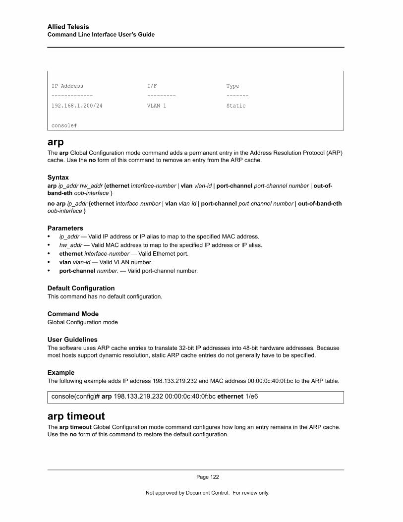
Allied Telesis Command Line Interface User’s Guide
arp The arp Global Configuration mode command adds a permanent entry in the Address Resolution Protocol (ARP) cache. Use the no form of this command to remove an entry from the ARP cache.
Syntaxarp ip_addr hw_addr {ethernet interface-number | vlan vlan-id | port-channel port-channel number | out-of-band-eth oob-interface }
no arp ip_addr {ethernet interface-number | vlan vlan-id | port-channel port-channel number | out-of-band-eth oob-interface }
Parameters• ip_addr — Valid IP address or IP alias to map to the specified MAC address.• hw_addr — Valid MAC address to map to the specified IP address or IP alias.• ethernet interface-number — Valid Ethernet port.• vlan vlan-id — Valid VLAN number.• port-channel number. — Valid port-channel number.
Default ConfigurationThis command has no default configuration.
Command ModeGlobal Configuration mode
User GuidelinesThe software uses ARP cache entries to translate 32-bit IP addresses into 48-bit hardware addresses. Because most hosts support dynamic resolution, static ARP cache entries do not generally have to be specified.
ExampleThe following example adds IP address 198.133.219.232 and MAC address 00:00:0c:40:0f:bc to the ARP table.
arp timeoutThe arp timeout Global Configuration mode command configures how long an entry remains in the ARP cache. Use the no form of this command to restore the default configuration.
IP Address I/F Type
------------- --------- -------
192.168.1.200/24 VLAN 1 Static
console#
console(config)# arp 198.133.219.232 00:00:0c:40:0f:bc ethernet 1/e6
Page 122
Not approved by Document Control. For review only.
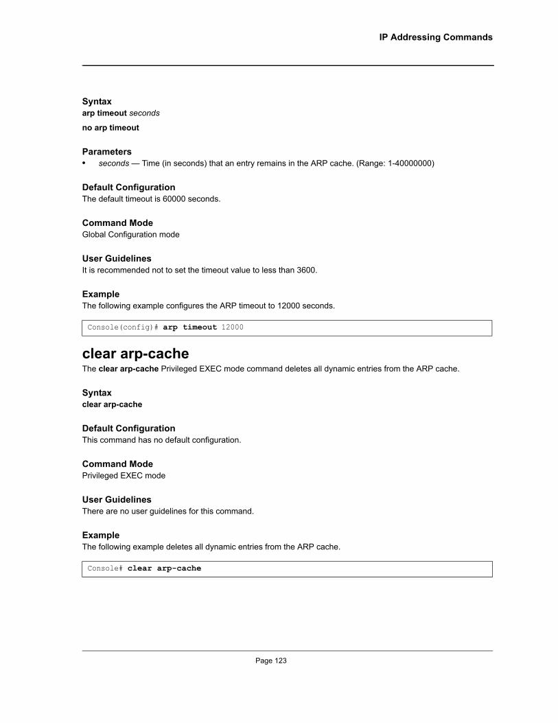
IP Addressing Commands
Syntaxarp timeout seconds
no arp timeout
Parameters• seconds — Time (in seconds) that an entry remains in the ARP cache. (Range: 1-40000000)
Default ConfigurationThe default timeout is 60000 seconds.
Command ModeGlobal Configuration mode
User GuidelinesIt is recommended not to set the timeout value to less than 3600.
ExampleThe following example configures the ARP timeout to 12000 seconds.
clear arp-cache The clear arp-cache Privileged EXEC mode command deletes all dynamic entries from the ARP cache.
Syntaxclear arp-cache
Default ConfigurationThis command has no default configuration.
Command ModePrivileged EXEC mode
User GuidelinesThere are no user guidelines for this command.
ExampleThe following example deletes all dynamic entries from the ARP cache.
Console(config)# arp timeout 12000
Console# clear arp-cache
Page 123
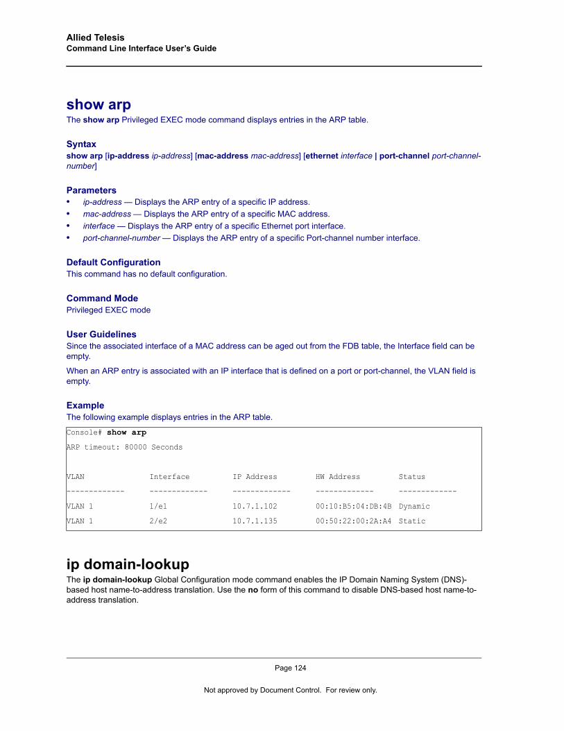
Allied Telesis Command Line Interface User’s Guide
show arpThe show arp Privileged EXEC mode command displays entries in the ARP table.
Syntaxshow arp [ip-address ip-address] [mac-address mac-address] [ethernet interface | port-channel port-channel-number]
Parameters• ip-address — Displays the ARP entry of a specific IP address.• mac-address — Displays the ARP entry of a specific MAC address.• interface — Displays the ARP entry of a specific Ethernet port interface.• port-channel-number — Displays the ARP entry of a specific Port-channel number interface.
Default ConfigurationThis command has no default configuration.
Command ModePrivileged EXEC mode
User GuidelinesSince the associated interface of a MAC address can be aged out from the FDB table, the Interface field can be empty.
When an ARP entry is associated with an IP interface that is defined on a port or port-channel, the VLAN field is empty.
ExampleThe following example displays entries in the ARP table.
ip domain-lookupThe ip domain-lookup Global Configuration mode command enables the IP Domain Naming System (DNS)-based host name-to-address translation. Use the no form of this command to disable DNS-based host name-to-address translation.
Console# show arp
ARP timeout: 80000 Seconds
VLAN Interface IP Address HW Address Status
------------- ------------- ------------- ------------- -------------
VLAN 1 1/e1 10.7.1.102 00:10:B5:04:DB:4B Dynamic
VLAN 1 2/e2 10.7.1.135 00:50:22:00:2A:A4 Static
Page 124
Not approved by Document Control. For review only.
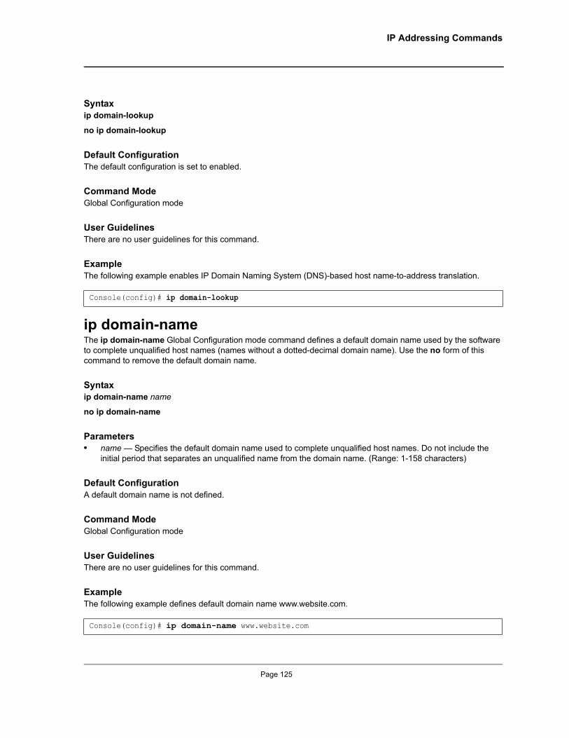
IP Addressing Commands
Syntaxip domain-lookup
no ip domain-lookup
Default Configuration The default configuration is set to enabled.
Command ModeGlobal Configuration mode
User GuidelinesThere are no user guidelines for this command.
ExampleThe following example enables IP Domain Naming System (DNS)-based host name-to-address translation.
ip domain-nameThe ip domain-name Global Configuration mode command defines a default domain name used by the software to complete unqualified host names (names without a dotted-decimal domain name). Use the no form of this command to remove the default domain name.
Syntaxip domain-name name
no ip domain-name
Parameters• name — Specifies the default domain name used to complete unqualified host names. Do not include the
initial period that separates an unqualified name from the domain name. (Range: 1-158 characters)
Default ConfigurationA default domain name is not defined.
Command Mode Global Configuration mode
User GuidelinesThere are no user guidelines for this command.
ExampleThe following example defines default domain name www.website.com.
Console(config)# ip domain-lookup
Console(config)# ip domain-name www.website.com
Page 125
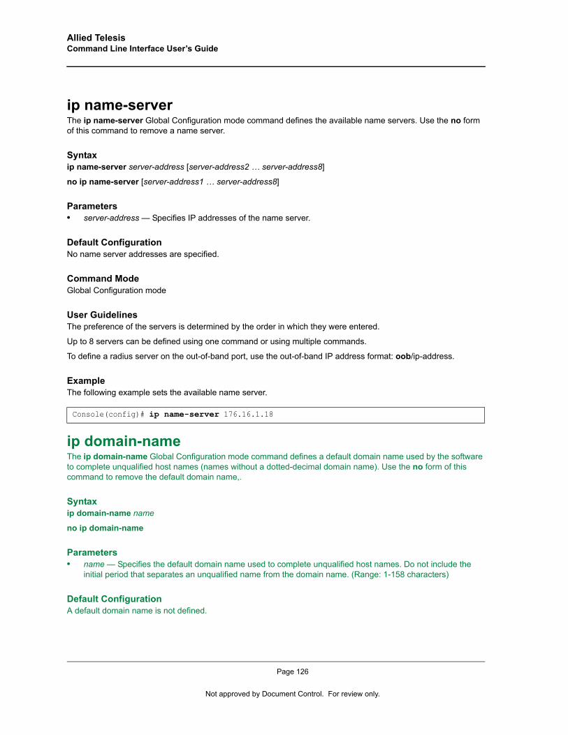
Allied Telesis Command Line Interface User’s Guide
ip name-serverThe ip name-server Global Configuration mode command defines the available name servers. Use the no form of this command to remove a name server.
Syntaxip name-server server-address [server-address2 … server-address8]
no ip name-server [server-address1 … server-address8]
Parameters• server-address — Specifies IP addresses of the name server.
Default ConfigurationNo name server addresses are specified.
Command Mode Global Configuration mode
User GuidelinesThe preference of the servers is determined by the order in which they were entered.
Up to 8 servers can be defined using one command or using multiple commands.
To define a radius server on the out-of-band port, use the out-of-band IP address format: oob/ip-address.
ExampleThe following example sets the available name server.
ip domain-nameThe ip domain-name Global Configuration mode command defines a default domain name used by the software to complete unqualified host names (names without a dotted-decimal domain name). Use the no form of this command to remove the default domain name,.
Syntaxip domain-name name
no ip domain-name
Parameters• name — Specifies the default domain name used to complete unqualified host names. Do not include the
initial period that separates an unqualified name from the domain name. (Range: 1-158 characters)
Default ConfigurationA default domain name is not defined.
Console(config)# ip name-server 176.16.1.18
Page 126
Not approved by Document Control. For review only.
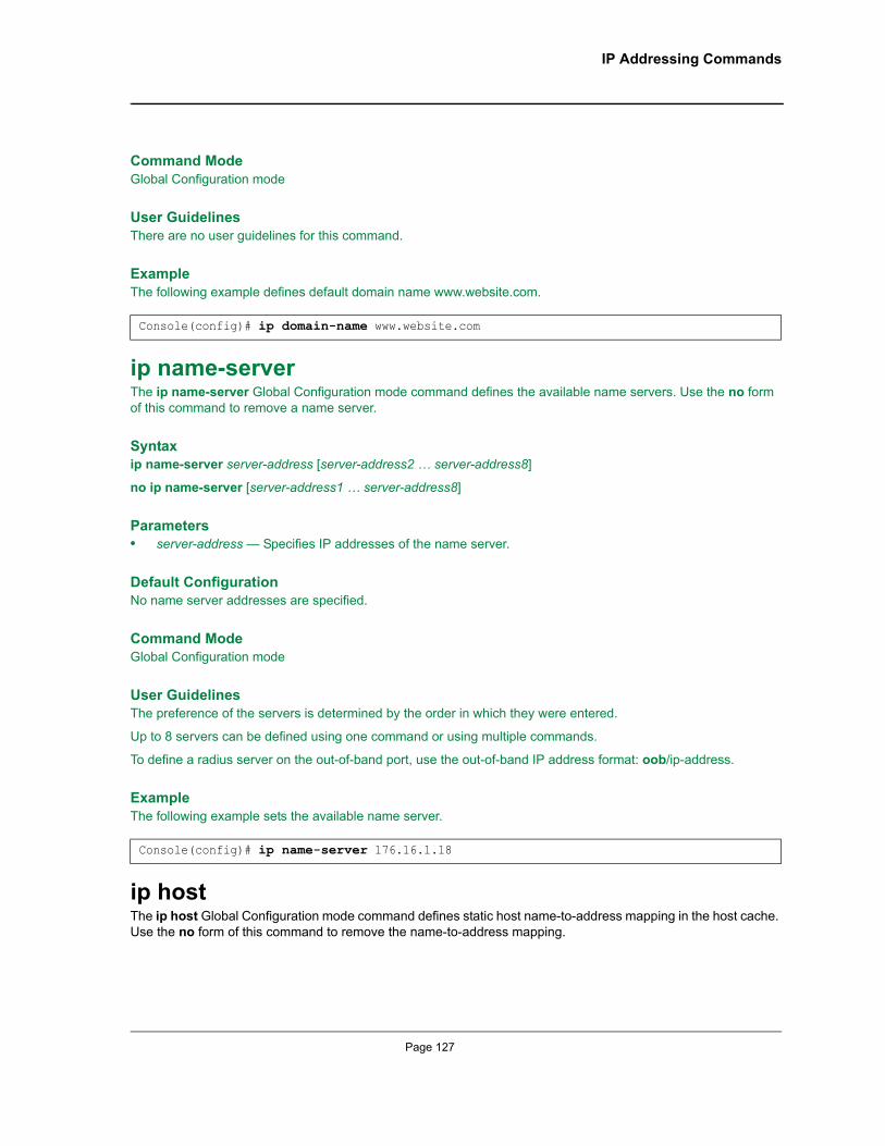
IP Addressing Commands
Command Mode Global Configuration mode
User GuidelinesThere are no user guidelines for this command.
ExampleThe following example defines default domain name www.website.com.
ip name-serverThe ip name-server Global Configuration mode command defines the available name servers. Use the no form of this command to remove a name server.
Syntaxip name-server server-address [server-address2 … server-address8]
no ip name-server [server-address1 … server-address8]
Parameters• server-address — Specifies IP addresses of the name server.
Default ConfigurationNo name server addresses are specified.
Command Mode Global Configuration mode
User GuidelinesThe preference of the servers is determined by the order in which they were entered.
Up to 8 servers can be defined using one command or using multiple commands.
To define a radius server on the out-of-band port, use the out-of-band IP address format: oob/ip-address.
ExampleThe following example sets the available name server.
ip hostThe ip host Global Configuration mode command defines static host name-to-address mapping in the host cache. Use the no form of this command to remove the name-to-address mapping.
Console(config)# ip domain-name www.website.com
Console(config)# ip name-server 176.16.1.18
Page 127
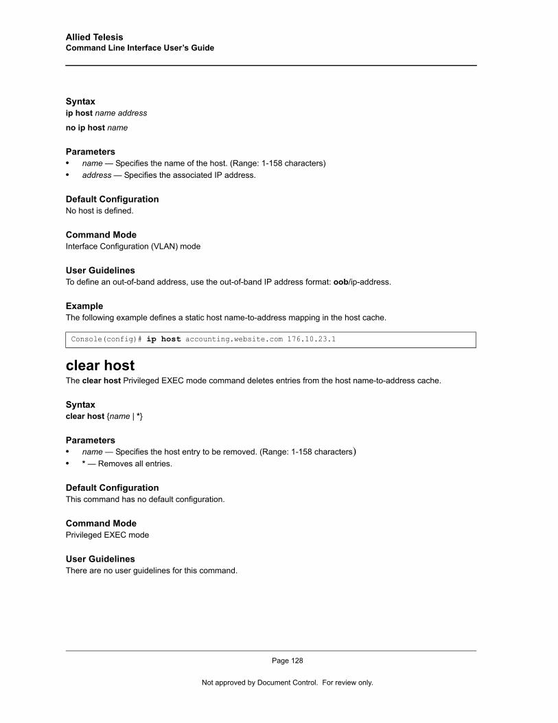
Allied Telesis Command Line Interface User’s Guide
Syntaxip host name address
no ip host name
Parameters• name — Specifies the name of the host. (Range: 1-158 characters)• address — Specifies the associated IP address.
Default Configuration No host is defined.
Command Mode Interface Configuration (VLAN) mode
User GuidelinesTo define an out-of-band address, use the out-of-band IP address format: oob/ip-address.
ExampleThe following example defines a static host name-to-address mapping in the host cache.
clear hostThe clear host Privileged EXEC mode command deletes entries from the host name-to-address cache.
Syntaxclear host {name | *}
Parameters• name — Specifies the host entry to be removed. (Range: 1-158 characters)• * — Removes all entries.
Default ConfigurationThis command has no default configuration.
Command Mode Privileged EXEC mode
User GuidelinesThere are no user guidelines for this command.
Console(config)# ip host accounting.website.com 176.10.23.1
Page 128
Not approved by Document Control. For review only.
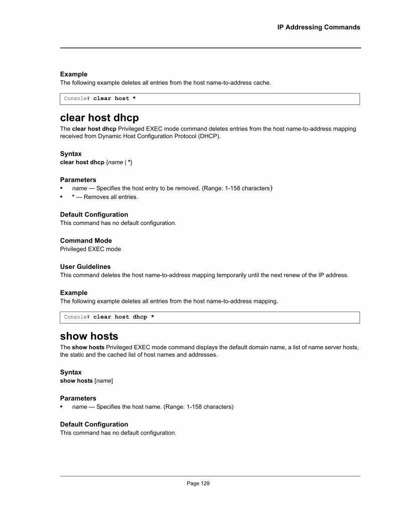
IP Addressing Commands
Example The following example deletes all entries from the host name-to-address cache.
clear host dhcpThe clear host dhcp Privileged EXEC mode command deletes entries from the host name-to-address mapping received from Dynamic Host Configuration Protocol (DHCP).
Syntaxclear host dhcp {name | *}
Parameters• name — Specifies the host entry to be removed. (Range: 1-158 characters)• * — Removes all entries.
Default ConfigurationThis command has no default configuration.
Command ModePrivileged EXEC mode
User GuidelinesThis command deletes the host name-to-address mapping temporarily until the next renew of the IP address.
Example The following example deletes all entries from the host name-to-address mapping.
show hostsThe show hosts Privileged EXEC mode command displays the default domain name, a list of name server hosts, the static and the cached list of host names and addresses.
Syntaxshow hosts [name]
Parameters• name — Specifies the host name. (Range: 1-158 characters)
Default ConfigurationThis command has no default configuration.
Console# clear host *
Console# clear host dhcp *
Page 129
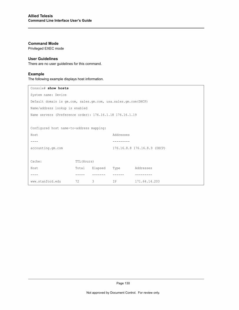
Allied Telesis Command Line Interface User’s Guide
Command Mode Privileged EXEC mode
User GuidelinesThere are no user guidelines for this command.
Example The following example displays host information.
Console# show hosts
System name: Device
Default domain is gm.com, sales.gm.com, usa.sales.gm.com(DHCP)
Name/address lookup is enabled
Name servers (Preference order): 176.16.1.18 176.16.1.19
Configured host name-to-address mapping:
Host Addresses
---- ---------
accounting.gm.com 176.16.8.8 176.16.8.9 (DHCP)
Cache: TTL(Hours)
Host Total Elapsed Type Addresses
---- ----- ------- ------ ---------
www.stanford.edu 72 3 IP 171.64.14.203
Page 130
Not approved by Document Control. For review only.
Line Commands
Chapter 13.Line Commands
lineThe line Global Configuration mode command identifies a specific line for configuration and enters the Line Configuration command mode.
Syntaxline {console | telnet | ssh}
Parameters• console — Console terminal line.• telnet — Virtual terminal for remote console access (Telnet).• ssh — Virtual terminal for secured remote console access (SSH).
Default ConfigurationThis command has no default configuration.
Command ModeGlobal Configuration mode
User GuidelinesThere are no user guidelines for this command.
ExampleThe following example configures the device as a virtual terminal for remote console access.
speedThe speed Line Configuration mode command sets the line baud rate. Use the no form of this command to return to the default configuration.
Syntaxspeed bps
no speed
Parameters• bps—Baud rate in bits per second (bps). Possible values are 2400, 9600, 19200, 38400, 57600 and 115200.
Console(config)# line telnetConsole(config-line)#
Page 131
Allied Telesis Command Line Interface User’s Guide
Default ConfigurationThe default speed is 9600 bps.
Command ModeLine Configuration (console) mode
User GuidelinesThis command is available only on the line console.
The configured speed is applied when Autobaud is disabled. This configuration applies only to the current session.
ExampleThe following example configures the line baud rate to 115200.
autobaudThe autobaud Line Configuration mode command sets the line for automatic baud rate detection (autobaud). Use the no form of this command to disable automatic baud rate detection.
Syntaxautobaud
no autobaud
Default ConfigurationAutobaud is disabled.
Command ModeLine Configuration (console) mode
User GuidelinesThis command is available only on the line console.
To start communication using Autobaud , press <Enter> twice. This configuration applies only to the current session.
ExampleThe following example enables autobaud.
Console(config)# line consoleConsole(config-line)# speed 115200
Console(config)# line consoleConsole(config-line)# autobaud
Page 132
Not approved by Document Control. For review only.
Line Commands
exec-timeoutThe exec-timeout Line Configuration mode command sets the interval that the system waits until user input is detected. Use the no form of this command to return to the default configuration.
Syntaxexec-timeout minutes [seconds]
no exec-timeout
Parameters• minutes — Specifies the number of minutes. (Range: 0 - 65535)• seconds — Specifies additional time intervals in seconds. (Range: 0 - 59)
Default ConfigurationThe default configuration is 10 minutes.
Command ModeLine Configuration mode
User GuidelinesTo specify no timeout, enter the exec-timeout 0 command.
ExampleThe following example configures the interval that the system waits until user input is detected to 20 minutes.
historyThe history Line Configuration mode command enables the command history function. Use the no form of this command to disable the command history function.
Syntaxhistory
no history
Default ConfigurationThe command history function is enabled.
Command ModeLine Configuration mode
User GuidelinesThis command enables the command history function for a specified line. To enable or disable the command history function for the current terminal session, use the terminal history user EXEC mode command.
Console(config)# line consoleConsole(config-line)# exec-timeout 20
Page 133
Allied Telesis Command Line Interface User’s Guide
ExampleThe following example enables the command history function for telnet.
history sizeThe history size Line Configuration mode command configures the command history buffer size for a particular line. Use the no form of this command to reset the command history buffer size to the default configuration.
Syntaxhistory size number-of-commands
no history size
Parameters• number-of-commands—Number of commands that the system records in its history buffer. (Range: 10 -206)
Default ConfigurationThe default history buffer size is 10.
Command ModeLine Configuration mode
User GuidelinesThis command configures the command history buffer size for a particular line. To configure the command history buffer size for the current terminal session, use the terminal history size User EXEC mode command.
ExampleThe following example changes the command history buffer size to 100 entries for a particular line.
terminal historyThe terminal history user EXEC command enables the command history function for the current terminal session. Use the no form of this command to disable the command history function.
Syntaxterminal history
terminal no history
Default ConfigurationThe default configuration for all terminal sessions is defined by the history line configuration command.
Console(config)# line telnetConsole(config-line)# history
Console(config-line)# history size 100
Page 134
Not approved by Document Control. For review only.
Line Commands
Command ModeUser EXEC mode
User GuidelinesThere are no user guidelines for this command.
ExampleThe following example disables the command history function for the current terminal session.
terminal history sizeThe terminal history size user EXEC command configures the command history buffer size for the current terminal session. Use the no form of this command to reset the command history buffer size to the default setting.
Syntaxterminal history size number-of-commands
terminal no history size
Parameters• number-of-commands—Specifies the number of commands the system may record in its command history
buffer. (Range: 10-206)
Default ConfigurationThe default command history buffer size is 10.
Command ModeUser EXEC mode
User GuidelinesThe terminal history size user EXEC command configures the size of the command history buffer for the current terminal session. Use the history line configuration command to change the default size of the command history buffer.
The maximum number of commands in all buffers is 256.
ExampleThe following example configures the command history buffer size to 20 commands for the current terminal session.
show lineThe show line User EXEC mode command displays line parameters.
Console# terminal no history
Console# terminal history size 20
Page 135

Allied Telesis Command Line Interface User’s Guide
Syntaxshow line [console | telnet | ssh]
Parameters• console — Console terminal line.• telnet — Virtual terminal for remote console access (Telnet).• ssh — Virtual terminal for secured remote console access (SSH).
Default ConfigurationIf the line is not specified, the default value is console.
Command ModeUser EXEC mode
User GuidelinesThere are no user guidelines for this command.
ExampleThe following example displays the line configuration.
Console> show line
Console configuration:
Interactive timeout: Disabled
History: 10
Baudrate: 9600
Databits: 8
Parity: none
Stopbits: 1
Telnet configuration:
Interactive timeout: 10 minutes 10 seconds
History: 10
SSH configuration:
Interactive timeout: 10 minutes 10 seconds
History: 10
Page 136
Not approved by Document Control. For review only.

Line Commands
Page 137
Allied Telesis Command Line Interface User’s Guide
Section 14.LACP Commands
lacp system-priorityThe lacp system-priority Global Configuration mode command configures the system priority. Use the no form of this command to return to the default configuration.
Syntaxlacp system-priority value
no lacp system-priority
Parameters• value — Specifies system priority value. (Range: 1 - 65535)
Default ConfigurationThe default system priority is 1.
Command ModeGlobal Configuration mode
User GuidelinesThere are no user guidelines for this command.
ExampleThe following example configures the system priority to 120.
Console(config)# lacp system-priority 120
Page 138
LACP Commands
lacp port-priorityThe lacp port-priority Interface Configuration (Ethernet) mode command configures physical port priority. Use the no form of this command to return to the default configuration, use the no form of this command.
Syntaxlacp port-priority value
no lacp port-priority
Parameters• value — Specifies port priority. (Range: 1 - 65535)
Default ConfigurationThe default port priority is 1.
Command ModeInterface Configuration (Ethernet) mode
User GuidelinesThere are no user guidelines for this command.
ExampleThe following example defines the priority of Ethernet port 1/e6 as 247.
Console(config)# interface ethernet 1/e6Console(config-if)# lacp port-priority 247
Page 139
Allied Telesis Command Line Interface User’s Guide
lacp timeoutThe lacp timeout Interface Configuration (Ethernet) mode command assigns an administrative LACP timeout. Use the no form of this command to return to the default configuration.
Syntaxlacp timeout {long | short}
no lacp timeout
Parameters• long — Specifies the long timeout value.• short — Specifies the short timeout value.
Default ConfigurationThe default port timeout value is long.
Command ModeInterface Configuration (Ethernet) mode
User GuidelinesThere are no user guidelines for this command.
ExampleThe following example assigns a long administrative LACP timeout to Ethernet port 1/e6 .
Console(config)# interface ethernet 1/e6Console(config-if)# lacp timeout long
Page 140
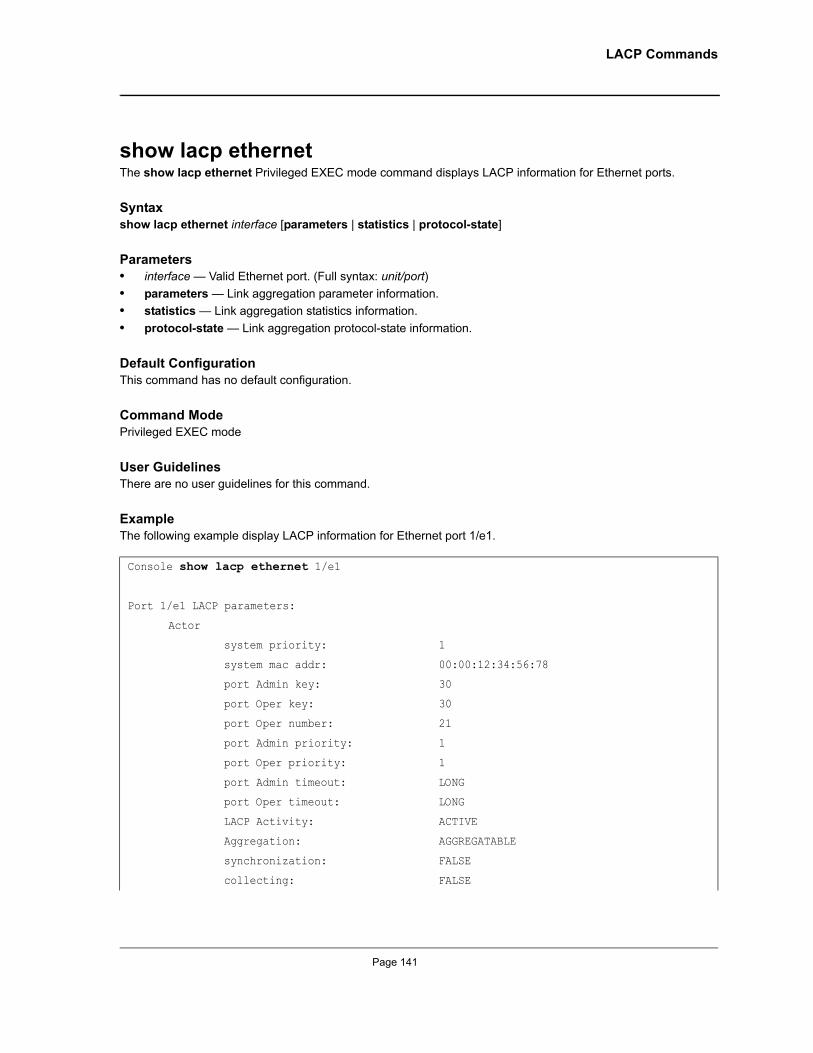
LACP Commands
show lacp ethernetThe show lacp ethernet Privileged EXEC mode command displays LACP information for Ethernet ports.
Syntaxshow lacp ethernet interface [parameters | statistics | protocol-state]
Parameters• interface — Valid Ethernet port. (Full syntax: unit/port)• parameters — Link aggregation parameter information.• statistics — Link aggregation statistics information.• protocol-state — Link aggregation protocol-state information.
Default ConfigurationThis command has no default configuration.
Command ModePrivileged EXEC mode
User GuidelinesThere are no user guidelines for this command.
ExampleThe following example display LACP information for Ethernet port 1/e1.
Console show lacp ethernet 1/e1
Port 1/e1 LACP parameters:
Actor
system priority: 1
system mac addr: 00:00:12:34:56:78
port Admin key: 30
port Oper key: 30
port Oper number: 21
port Admin priority: 1
port Oper priority: 1
port Admin timeout: LONG
port Oper timeout: LONG
LACP Activity: ACTIVE
Aggregation: AGGREGATABLE
synchronization: FALSE
collecting: FALSE
Page 141
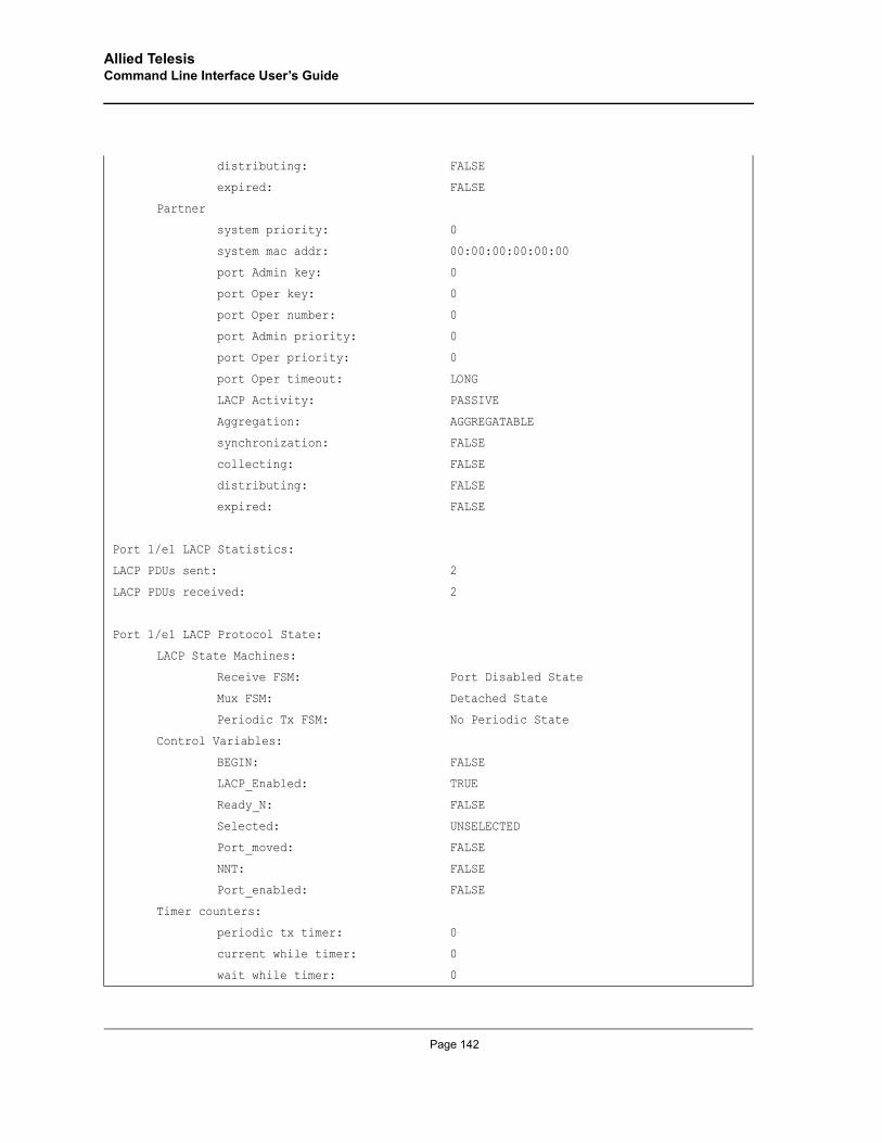
Allied Telesis Command Line Interface User’s Guide
distributing: FALSE
expired: FALSE
Partner
system priority: 0
system mac addr: 00:00:00:00:00:00
port Admin key: 0
port Oper key: 0
port Oper number: 0
port Admin priority: 0
port Oper priority: 0
port Oper timeout: LONG
LACP Activity: PASSIVE
Aggregation: AGGREGATABLE
synchronization: FALSE
collecting: FALSE
distributing: FALSE
expired: FALSE
Port 1/e1 LACP Statistics:
LACP PDUs sent: 2
LACP PDUs received: 2
Port 1/e1 LACP Protocol State:
LACP State Machines:
Receive FSM: Port Disabled State
Mux FSM: Detached State
Periodic Tx FSM: No Periodic State
Control Variables:
BEGIN: FALSE
LACP_Enabled: TRUE
Ready_N: FALSE
Selected: UNSELECTED
Port_moved: FALSE
NNT: FALSE
Port_enabled: FALSE
Timer counters:
periodic tx timer: 0
current while timer: 0
wait while timer: 0
Page 142
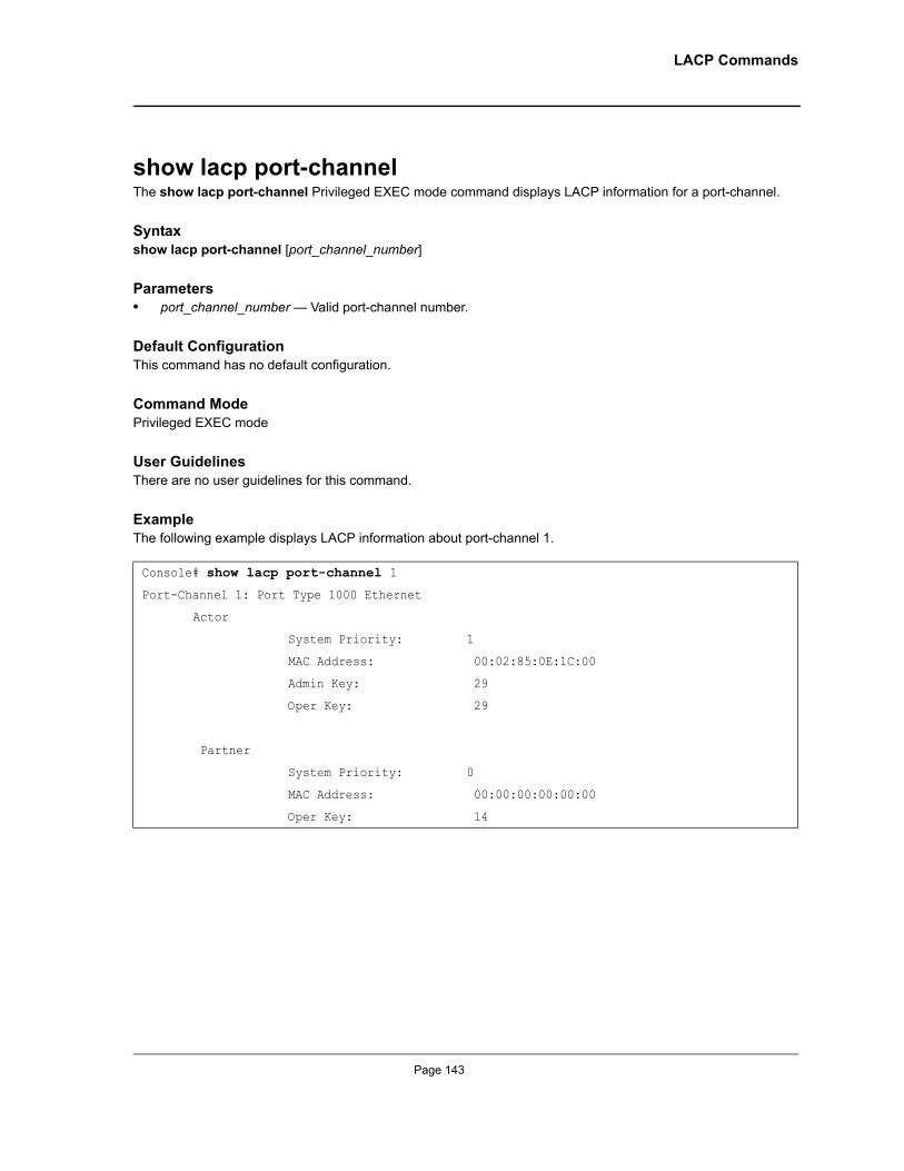
LACP Commands
show lacp port-channelThe show lacp port-channel Privileged EXEC mode command displays LACP information for a port-channel.
Syntaxshow lacp port-channel [port_channel_number]
Parameters• port_channel_number — Valid port-channel number.
Default ConfigurationThis command has no default configuration.
Command ModePrivileged EXEC mode
User GuidelinesThere are no user guidelines for this command.
ExampleThe following example displays LACP information about port-channel 1.
Console# show lacp port-channel 1
Port-Channel 1: Port Type 1000 Ethernet
Actor
System Priority: 1
MAC Address: 00:02:85:0E:1C:00
Admin Key: 29
Oper Key: 29
Partner
System Priority: 0
MAC Address: 00:00:00:00:00:00
Oper Key: 14
Page 143
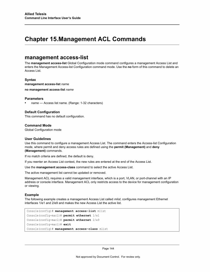
Allied Telesis Command Line Interface User’s Guide
Chapter 15.Management ACL Commands
management access-listThe management access-list Global Configuration mode command configures a management Access List and enters the Management Access-list Configuration command mode. Use the no form of this command to delete an Access List.
Syntaxmanagement access-list name
no management access-list name
Parameters• name — Access list name. (Range: 1-32 characters)
Default ConfigurationThis command has no default configuration.
Command ModeGlobal Configuration mode
User GuidelinesUse this command to configure a management Access List. The command enters the Access-list Configuration mode, where permit and deny access rules are defined using the permit (Management) and deny (Management) commands.
If no match criteria are defined, the default is deny.
If you reenter an Access List context, the new rules are entered at the end of the Access List.
Use the management access-class command to select the active Access List.
The active management list cannot be updated or removed.
Management ACL requires a valid management interface, which is a port, VLAN, or port-channel with an IP address or console interface. Management ACL only restricts access to the device for management configuration or viewing.
ExampleThe following example creates a management Access List called mlist, configures management Ethernet interfaces 1/e1 and 2/e9 and makes the new Access List the active list.
Console(config)# management access-list mlistConsole(config-macl)# permit ethernet 1/e1Console(config-macl)# permit ethernet 2/e9Console(config-macl)# exitConsole(config)# management access-class mlist
Page 144
Not approved by Document Control. For review only.
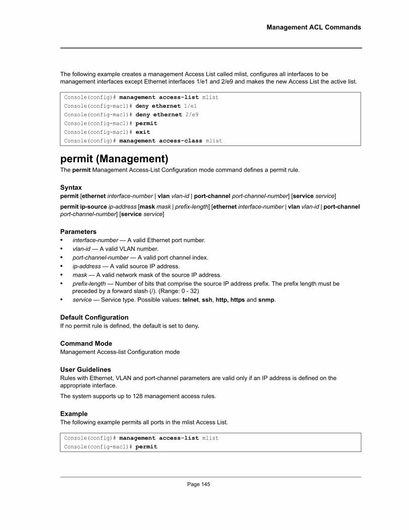
Management ACL Commands
The following example creates a management Access List called mlist, configures all interfaces to be management interfaces except Ethernet interfaces 1/e1 and 2/e9 and makes the new Access List the active list.
permit (Management)The permit Management Access-List Configuration mode command defines a permit rule.
Syntaxpermit [ethernet interface-number | vlan vlan-id | port-channel port-channel-number] [service service]
permit ip-source ip-address [mask mask | prefix-length] [ethernet interface-number | vlan vlan-id | port-channel port-channel-number] [service service]
Parameters• interface-number — A valid Ethernet port number.• vlan-id — A valid VLAN number.• port-channel-number — A valid port channel index.• ip-address — A valid source IP address.• mask — A valid network mask of the source IP address. • prefix-length — Number of bits that comprise the source IP address prefix. The prefix length must be
preceded by a forward slash (/). (Range: 0 - 32)• service — Service type. Possible values: telnet, ssh, http, https and snmp.
Default ConfigurationIf no permit rule is defined, the default is set to deny.
Command ModeManagement Access-list Configuration mode
User GuidelinesRules with Ethernet, VLAN and port-channel parameters are valid only if an IP address is defined on the appropriate interface.
The system supports up to 128 management access rules.
ExampleThe following example permits all ports in the mlist Access List.
Console(config)# management access-list mlistConsole(config-macl)# deny ethernet 1/e1Console(config-macl)# deny ethernet 2/e9Console(config-macl)# permitConsole(config-macl)# exitConsole(config)# management access-class mlist
Console(config)# management access-list mlistConsole(config-macl)# permit
Page 145
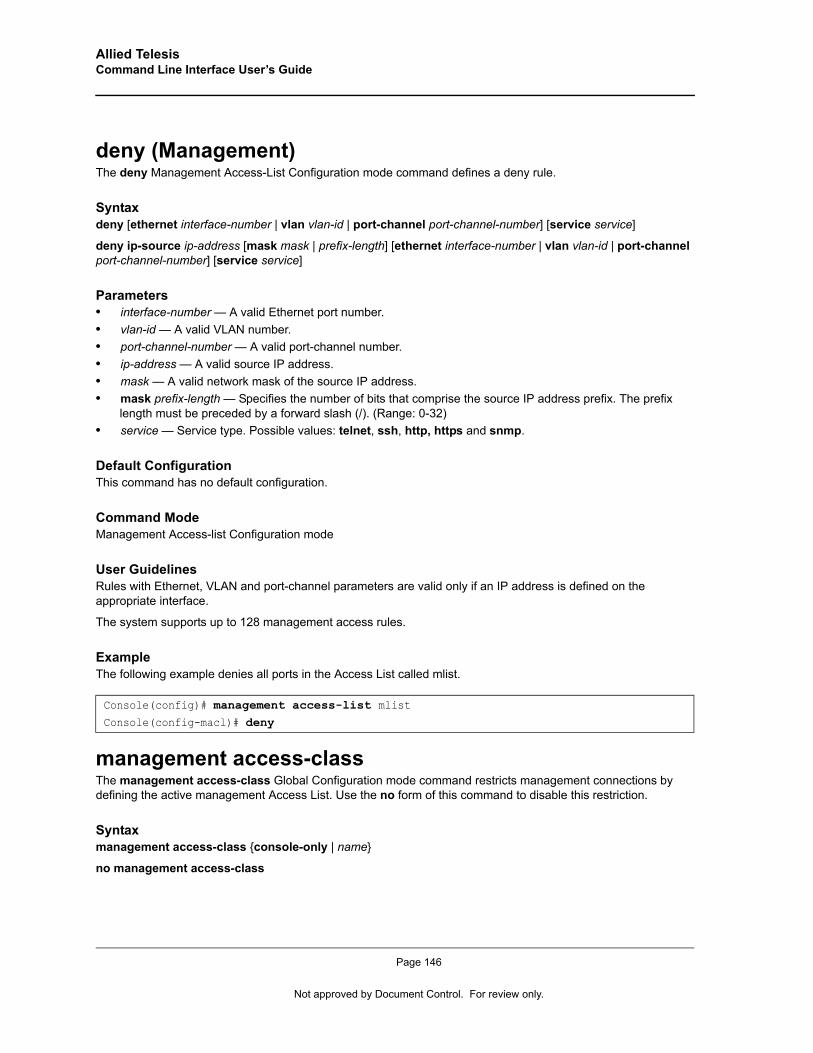
Allied Telesis Command Line Interface User’s Guide
deny (Management)The deny Management Access-List Configuration mode command defines a deny rule.
Syntaxdeny [ethernet interface-number | vlan vlan-id | port-channel port-channel-number] [service service]
deny ip-source ip-address [mask mask | prefix-length] [ethernet interface-number | vlan vlan-id | port-channel port-channel-number] [service service]
Parameters• interface-number — A valid Ethernet port number.• vlan-id — A valid VLAN number.• port-channel-number — A valid port-channel number.• ip-address — A valid source IP address. • mask — A valid network mask of the source IP address. • mask prefix-length — Specifies the number of bits that comprise the source IP address prefix. The prefix
length must be preceded by a forward slash (/). (Range: 0-32)• service — Service type. Possible values: telnet, ssh, http, https and snmp.
Default ConfigurationThis command has no default configuration.
Command ModeManagement Access-list Configuration mode
User GuidelinesRules with Ethernet, VLAN and port-channel parameters are valid only if an IP address is defined on the appropriate interface.
The system supports up to 128 management access rules.
ExampleThe following example denies all ports in the Access List called mlist.
management access-classThe management access-class Global Configuration mode command restricts management connections by defining the active management Access List. Use the no form of this command to disable this restriction.
Syntaxmanagement access-class {console-only | name}
no management access-class
Console(config)# management access-list mlistConsole(config-macl)# deny
Page 146
Not approved by Document Control. For review only.
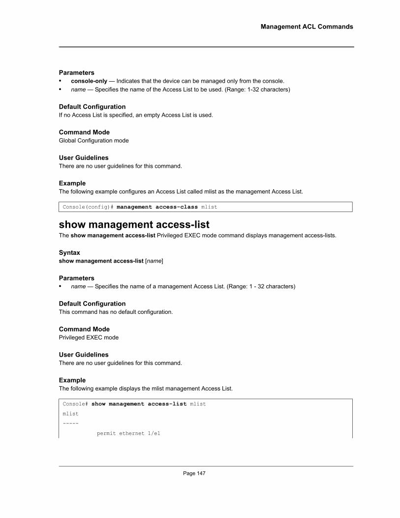
Management ACL Commands
Parameters• console-only — Indicates that the device can be managed only from the console.• name — Specifies the name of the Access List to be used. (Range: 1-32 characters)
Default ConfigurationIf no Access List is specified, an empty Access List is used.
Command ModeGlobal Configuration mode
User GuidelinesThere are no user guidelines for this command.
ExampleThe following example configures an Access List called mlist as the management Access List.
show management access-listThe show management access-list Privileged EXEC mode command displays management access-lists.
Syntaxshow management access-list [name]
Parameters• name — Specifies the name of a management Access List. (Range: 1 - 32 characters)
Default ConfigurationThis command has no default configuration.
Command ModePrivileged EXEC mode
User GuidelinesThere are no user guidelines for this command.
ExampleThe following example displays the mlist management Access List.
Console(config)# management access-class mlist
Console# show management access-list mlist
mlist
-----
permit ethernet 1/e1
Page 147
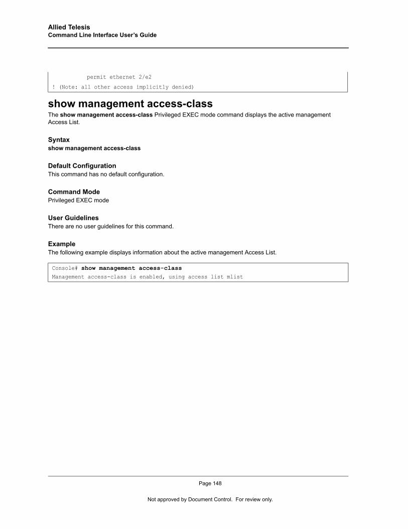
Allied Telesis Command Line Interface User’s Guide
show management access-class The show management access-class Privileged EXEC mode command displays the active management Access List.
Syntaxshow management access-class
Default ConfigurationThis command has no default configuration.
Command ModePrivileged EXEC mode
User GuidelinesThere are no user guidelines for this command.
ExampleThe following example displays information about the active management Access List.
permit ethernet 2/e2
! (Note: all other access implicitly denied)
Console# show management access-classManagement access-class is enabled, using access list mlist
Page 148
Not approved by Document Control. For review only.
PHY Diagnostics Commands
Chapter 16.PHY Diagnostics Commands
test copper-port tdrThe test copper-port tdr Privileged EXEC mode command uses Time Domain Reflectometry (TDR) technology to diagnose the quality and characteristics of a copper cable attached to a port.
Syntaxtest copper-port tdr interface
Parameters• interface — A valid Ethernet port. (Full syntax: unit/port)
Default ConfigurationThis command has no default configuration.
Command ModePrivileged EXEC mode
User GuidelinesThe port to be tested should be shut down during the test, unless it is a combination port with fiber port active.
The maximum length of the cable for the TDR test is 120 meter.
ExampleThe following example results in a report on the cable attached to port 1/e3.
show copper-ports tdrThe show copper-ports tdr User EXEC mode command displays information on the last Time Domain Reflectometry (TDR) test performed on copper ports.
Syntaxshow copper-ports tdr [interface]
Parameters• interface — A valid Ethernet port. (Full syntax: unit/port)
Console# test copper-port tdr 1/e3Cable is open at 64 meters
Console# test copper-port tdr 2/e3Can’t perform this test on fiber ports
Page 149
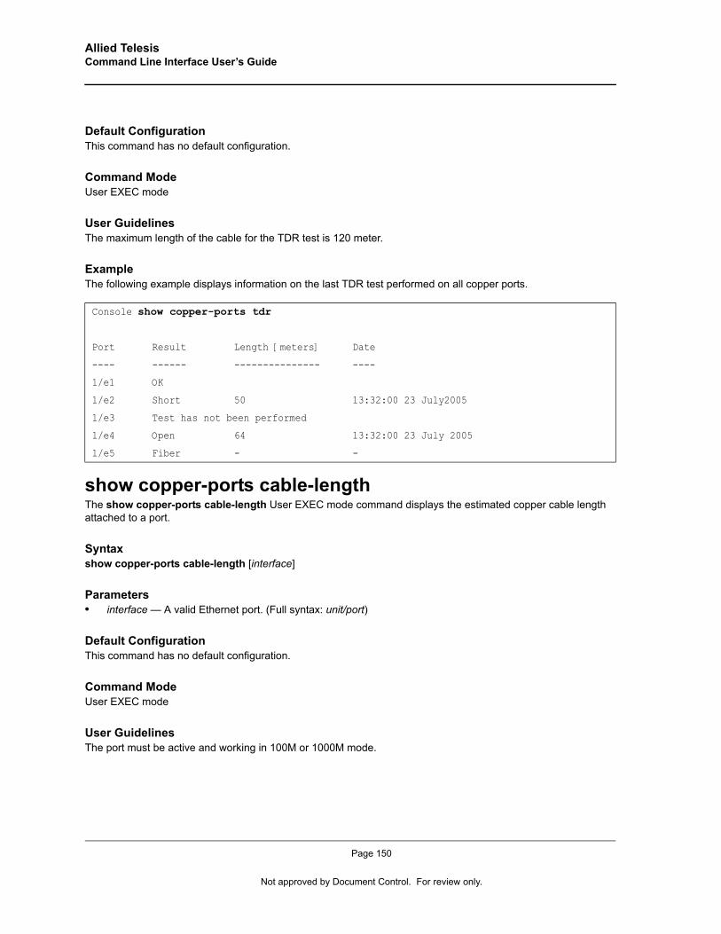
Allied Telesis Command Line Interface User’s Guide
Default ConfigurationThis command has no default configuration.
Command ModeUser EXEC mode
User GuidelinesThe maximum length of the cable for the TDR test is 120 meter.
ExampleThe following example displays information on the last TDR test performed on all copper ports.
show copper-ports cable-lengthThe show copper-ports cable-length User EXEC mode command displays the estimated copper cable length attached to a port.
Syntaxshow copper-ports cable-length [interface]
Parameters• interface — A valid Ethernet port. (Full syntax: unit/port)
Default ConfigurationThis command has no default configuration.
Command ModeUser EXEC mode
User GuidelinesThe port must be active and working in 100M or 1000M mode.
Console show copper-ports tdr
Port Result Length [meters] Date
---- ------ --------------- ----
1/e1 OK
1/e2 Short 50 13:32:00 23 July2005
1/e3 Test has not been performed
1/e4 Open 64 13:32:00 23 July 2005
1/e5 Fiber - -
Page 150
Not approved by Document Control. For review only.
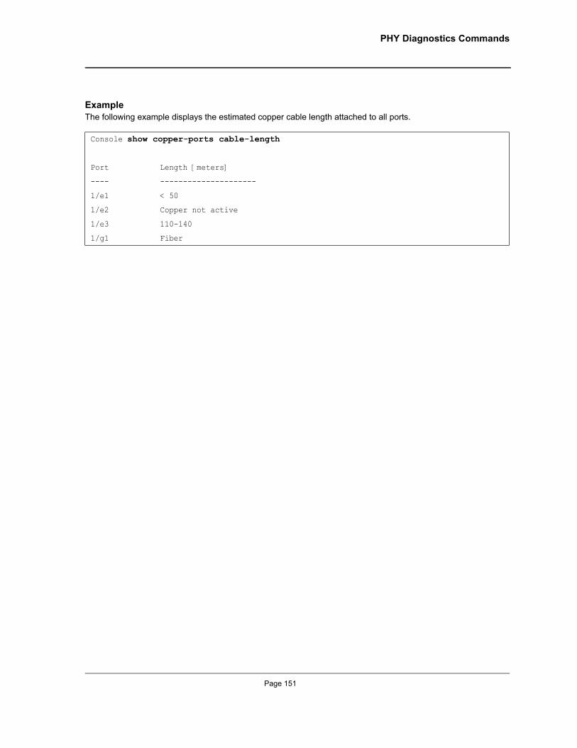
PHY Diagnostics Commands
ExampleThe following example displays the estimated copper cable length attached to all ports.
Console show copper-ports cable-length
Port Length [meters]
---- ---------------------
1/e1 < 50
1/e2 Copper not active
1/e3 110-140
1/g1 Fiber
Page 151
Allied Telesis Command Line Interface User’s Guide
Chapter 17.Port Channel Commands
interface port-channelThe interface port-channel Global Configuration mode command enters the interface configuration mode to configure a specific port-channel.
Syntaxinterface port-channel port-channel-number
Parameters• port-channel-number — A valid port-channel number.
Default ConfigurationThis command has no default configuration.
Command ModeGlobal Configuration mode
User GuidelinesEight aggregated links can be defined with up to eight member ports per port-channel. The aggregated links’ valid IDs are 1-8.
ExampleThe following example enters the context of port-channel number 1.
interface range port-channelThe interface range port-channel Global Configuration mode command enters the interface configuration mode to configure multiple port-channels.
Syntaxinterface range port-channel {port-channel-range | all}
Parameters• port-channel-range — List of valid port-channels to add. Separate nonconsecutive port-channels with a
comma and no spaces. A hyphen designates a range of port-channels.• all — All valid port-channels.
Default ConfigurationThis command has no default configuration.
Console(config)# interface port-channel 1
Page 152
Not approved by Document Control. For review only.
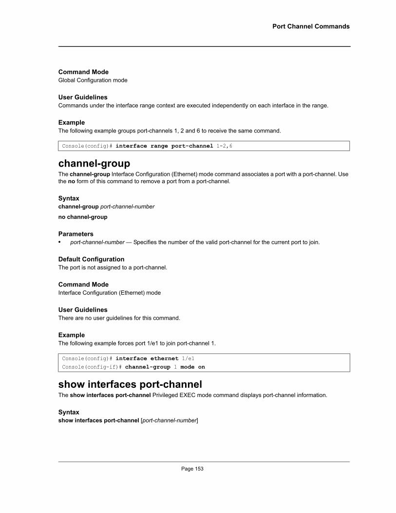
Port Channel Commands
Command ModeGlobal Configuration mode
User GuidelinesCommands under the interface range context are executed independently on each interface in the range.
ExampleThe following example groups port-channels 1, 2 and 6 to receive the same command.
channel-groupThe channel-group Interface Configuration (Ethernet) mode command associates a port with a port-channel. Use the no form of this command to remove a port from a port-channel.
Syntaxchannel-group port-channel-number
no channel-group
Parameters• port-channel-number — Specifies the number of the valid port-channel for the current port to join.
Default ConfigurationThe port is not assigned to a port-channel.
Command ModeInterface Configuration (Ethernet) mode
User GuidelinesThere are no user guidelines for this command.
ExampleThe following example forces port 1/e1 to join port-channel 1.
show interfaces port-channelThe show interfaces port-channel Privileged EXEC mode command displays port-channel information.
Syntaxshow interfaces port-channel [port-channel-number]
Console(config)# interface range port-channel 1-2,6
Console(config)# interface ethernet 1/e1Console(config-if)# channel-group 1 mode on
Page 153
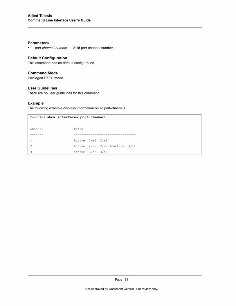
Allied Telesis Command Line Interface User’s Guide
Parameters• port-channel-number — Valid port-channel number.
Default ConfigurationThis command has no default configuration.
Command ModePrivileged EXEC mode
User GuidelinesThere are no user guidelines for this command.
ExampleThe following example displays information on all port-channels.
Console# show interfaces port-channel
Channel Ports
------- ---------------------------------
1 Active: 1/e1, 2/e2
2 Active: 2/e2, 2/e7 Inactive: 3/e1
3 Active: 3/e3, 3/e8
Page 154
Not approved by Document Control. For review only.
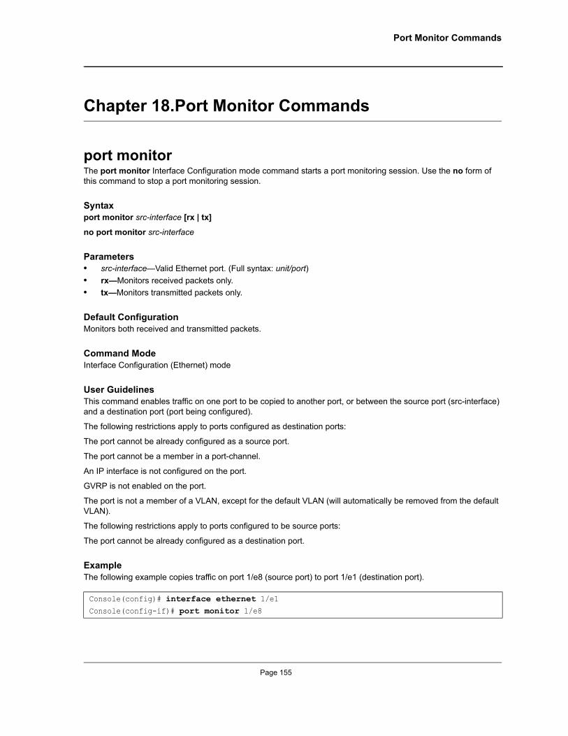
Port Monitor Commands
Chapter 18.Port Monitor Commands
port monitorThe port monitor Interface Configuration mode command starts a port monitoring session. Use the no form of this command to stop a port monitoring session.
Syntaxport monitor src-interface [rx | tx]
no port monitor src-interface
Parameters• src-interface—Valid Ethernet port. (Full syntax: unit/port)• rx—Monitors received packets only.• tx—Monitors transmitted packets only.
Default ConfigurationMonitors both received and transmitted packets.
Command ModeInterface Configuration (Ethernet) mode
User GuidelinesThis command enables traffic on one port to be copied to another port, or between the source port (src-interface) and a destination port (port being configured).
The following restrictions apply to ports configured as destination ports:
The port cannot be already configured as a source port.
The port cannot be a member in a port-channel.
An IP interface is not configured on the port.
GVRP is not enabled on the port.
The port is not a member of a VLAN, except for the default VLAN (will automatically be removed from the default VLAN).
The following restrictions apply to ports configured to be source ports:
The port cannot be already configured as a destination port.
ExampleThe following example copies traffic on port 1/e8 (source port) to port 1/e1 (destination port).
Console(config)# interface ethernet 1/e1Console(config-if)# port monitor 1/e8
Page 155
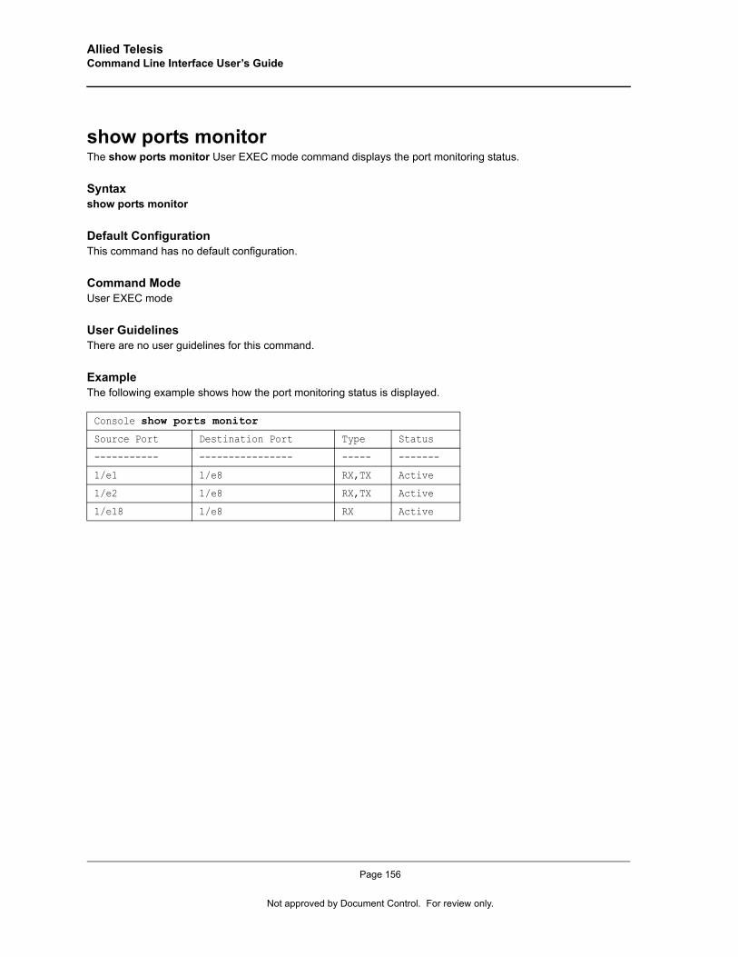
Allied Telesis Command Line Interface User’s Guide
show ports monitorThe show ports monitor User EXEC mode command displays the port monitoring status.
Syntaxshow ports monitor
Default ConfigurationThis command has no default configuration.
Command ModeUser EXEC mode
User GuidelinesThere are no user guidelines for this command.
ExampleThe following example shows how the port monitoring status is displayed.
Console show ports monitor
Source Port Destination Port Type Status
----------- ---------------- ----- -------
1/e1 1/e8 RX,TX Active
1/e2 1/e8 RX,TX Active
1/e18 1/e8 RX Active
Page 156
Not approved by Document Control. For review only.
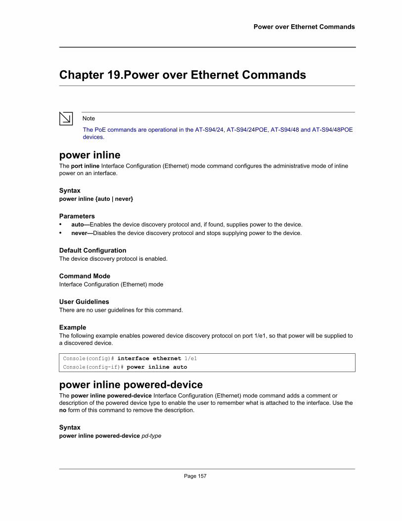
Power over Ethernet Commands
Chapter 19.Power over Ethernet Commands
Note
The PoE commands are operational in the AT-S94/24, AT-S94/24POE, AT-S94/48 and AT-S94/48POE devices.
power inlineThe port inline Interface Configuration (Ethernet) mode command configures the administrative mode of inline power on an interface.
Syntaxpower inline {auto | never}
Parameters• auto—Enables the device discovery protocol and, if found, supplies power to the device.• never—Disables the device discovery protocol and stops supplying power to the device.
Default ConfigurationThe device discovery protocol is enabled.
Command ModeInterface Configuration (Ethernet) mode
User GuidelinesThere are no user guidelines for this command.
ExampleThe following example enables powered device discovery protocol on port 1/e1, so that power will be supplied to a discovered device.
power inline powered-deviceThe power inline powered-device Interface Configuration (Ethernet) mode command adds a comment or description of the powered device type to enable the user to remember what is attached to the interface. Use the no form of this command to remove the description.
Syntaxpower inline powered-device pd-type
Console(config)# interface ethernet 1/e1Console(config-if)# power inline auto
Page 157
Allied Telesis Command Line Interface User’s Guide
no power inline powered-device
Parameters• pd-type—Specifies the type of powered device attached to the interface. (Range: 1-24 characters)
Default ConfigurationThis command has no default configuration.
Command ModeInterface Configuration (Ethernet) mode
User GuidelinesThere are no user guidelines for this command.
ExampleThe following example configures a description to an IP-phone to a powered device connected to Ethernet interface 1/e1.
power inline priorityThe power inline priority Interface Configuration (Ethernet) mode command configures the inline power management priority of the interface. Use the no form of this command to return to the default configuration.
Syntaxpower inline priority {critical | high | low}
no power inline priority
Parameters• critical — Indicates that operating the powered device is critical.• high — Indicates that operating the powered device has high priority.• low—Indicates that operating the powered device has low priority.
Default ConfigurationThe default setting is low priority.
Command ModeInterface Configuration (Ethernet) mode
User GuidelinesThere are no user guidelines for this command.
Console(config)# interface ethernet 1/e1Console(config-if)# power inline powered-device IP-phone
Page 158
Not approved by Document Control. For review only.
Power over Ethernet Commands
ExampleThe following example configures the device connected to Ethernet interface 1/e1 as a high-priority powered device.
power inline usage-thresholdThe power inline usage-threshold Global Configuration mode command configures the threshold for initiating inline power usage alarms. Use the no form of this command to return to the default configuration.
Syntaxpower inline usage-threshold percentage
no power inline usage-threshold
Parameters• percentage—Specifies the threshold as a percentage to compare measured power. (Range: 1-99)
Default ConfigurationThe default threshold is 95 percent.
Command ModeGlobal Configuration mode
User GuidelinesThere are no user guidelines for this command.
ExampleThe following example configures the power usage threshold for which alarms are sent to 80%.
power inline traps enableThe power inline traps enable Global Configuration mode command enables inline power traps. Use the no form of this command to disable inline power traps.
Syntaxpower inline traps enable
no power inline traps enable
Default ConfigurationInline power traps are disabled.
Console(config)# interface ethernet 1/e1Console(config-if)# power inline priority high
Console(config)# power inline usage-threshold 80
Page 159
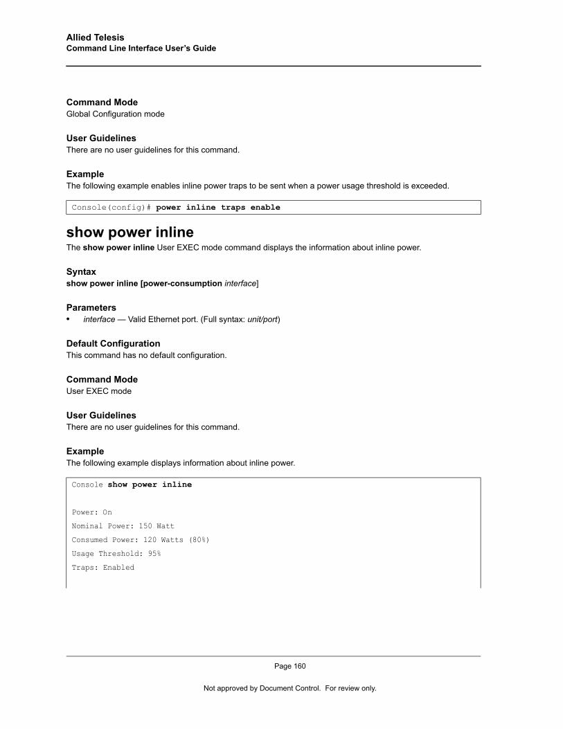
Allied Telesis Command Line Interface User’s Guide
Command ModeGlobal Configuration mode
User GuidelinesThere are no user guidelines for this command.
ExampleThe following example enables inline power traps to be sent when a power usage threshold is exceeded.
show power inlineThe show power inline User EXEC mode command displays the information about inline power.
Syntaxshow power inline [power-consumption interface]
Parameters• interface — Valid Ethernet port. (Full syntax: unit/port)
Default ConfigurationThis command has no default configuration.
Command ModeUser EXEC mode
User GuidelinesThere are no user guidelines for this command.
ExampleThe following example displays information about inline power.
Console(config)# power inline traps enable
Console show power inline
Power: On
Nominal Power: 150 Watt
Consumed Power: 120 Watts (80%)
Usage Threshold: 95%
Traps: Enabled
Page 160
Not approved by Document Control. For review only.
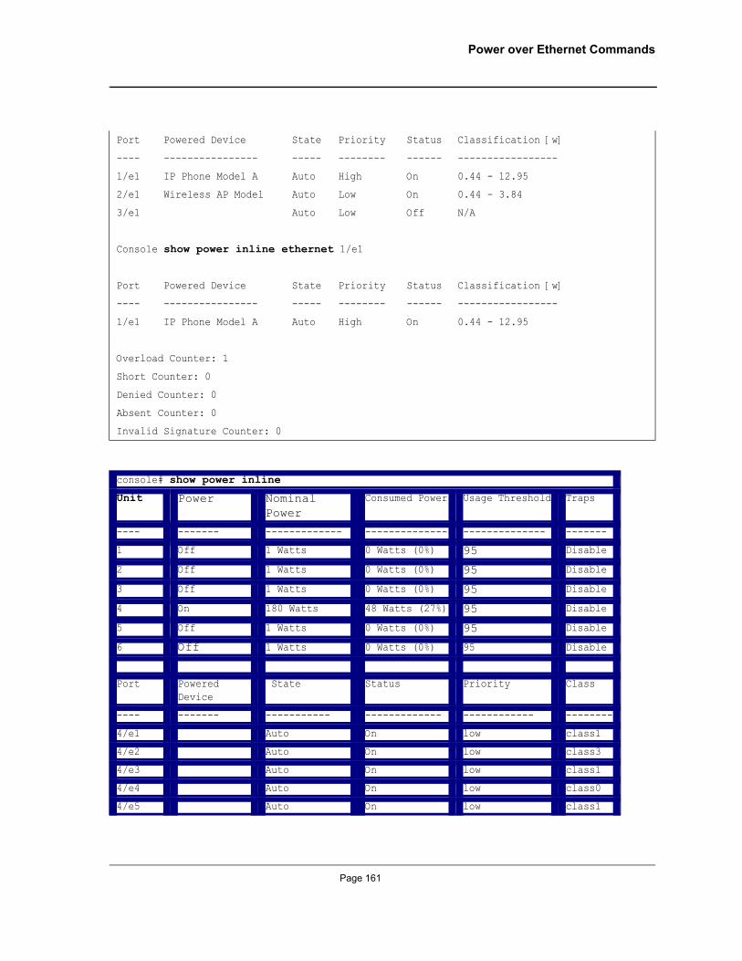
Power over Ethernet Commands
Port Powered Device State Priority Status Classification [w]
---- ---------------- ----- -------- ------ -----------------
1/e1 IP Phone Model A Auto High On 0.44 - 12.95
2/e1 Wireless AP Model Auto Low On 0.44 - 3.84
3/e1 Auto Low Off N/A
Console show power inline ethernet 1/e1
Port Powered Device State Priority Status Classification [w]
---- ---------------- ----- -------- ------ -----------------
1/e1 IP Phone Model A Auto High On 0.44 - 12.95
Overload Counter: 1
Short Counter: 0
Denied Counter: 0
Absent Counter: 0
Invalid Signature Counter: 0
console# show power inline
Unit Power Nominal Power
Consumed Power Usage Threshold Traps
---- ------- ------------- -------------- -------------- -------
1 Off 1 Watts 0 Watts (0%) 95 Disable
2 Off 1 Watts 0 Watts (0%) 95 Disable
3 Off 1 Watts 0 Watts (0%) 95 Disable
4 On 180 Watts 48 Watts (27%) 95 Disable
5 Off 1 Watts 0 Watts (0%) 95 Disable
6 Off 1 Watts 0 Watts (0%) 95 Disable
Port Powered Device
State Status Priority Class
---- ------- ----------- ------------- ------------ --------
4/e1 Auto On low class1
4/e2 Auto On low class3
4/e3 Auto On low class1
4/e4 Auto On low class0
4/e5 Auto On low class1
Page 161
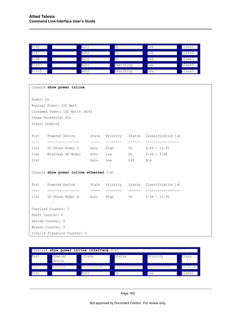
Allied Telesis Command Line Interface User’s Guide
.
4/e6 Auto On low class2
4/e7 Auto On low class4
4/e8 Auto On low class3
4/e9 Auto Searching low class0
4/e10 Auto Searching low class0
Console show power inline
Power: On
Nominal Power: 150 Watt
Consumed Power: 120 Watts (80%)
Usage Threshold: 95%
Traps: Enabled
Port Powered Device State Priority Status Classification [w]
---- ---------------- ----- -------- ------ -----------------
1/e1 IP Phone Model A Auto High On 0.44 - 12.95
2/e1 Wireless AP Model Auto Low On 0.44 - 3.84
3/e1 Auto Low Off N/A
Console show power inline ethernet 1/e1
Port Powered Device State Priority Status Classification [w]
---- ---------------- ----- -------- ------ -----------------
1/e1 IP Phone Model A Auto High On 0.44 - 12.95
Overload Counter: 1
Short Counter: 0
Denied Counter: 0
Absent Counter: 0
Invalid Signature Counter: 0
console# show power inline interface 4/e1
Port Powered Device
State Status Priority Class
---- ------- ----------- ------------- ------------ --------
4/e1 Auto On low class1
Page 162
Not approved by Document Control. For review only.
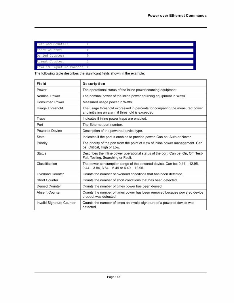
Power over Ethernet Commands
The following table describes the significant fields shown in the example:
Overload Counter: 0
Short Counter: 0
Denied Counter: 0
Absent Counter: 1
Invalid Signature Counter: 0
Field Description
Power The operational status of the inline power sourcing equipment.
Nominal Power The nominal power of the inline power sourcing equipment in Watts.
Consumed Power Measured usage power in Watts.
Usage Threshold The usage threshold expressed in percents for comparing the measured power and initiating an alarm if threshold is exceeded.
Traps Indicates if inline power traps are enabled.
Port The Ethernet port number.
Powered Device Description of the powered device type.
State Indicates if the port is enabled to provide power. Can be: Auto or Never.
Priority The priority of the port from the point of view of inline power management. Can be: Critical, High or Low.
Status Describes the inline power operational status of the port. Can be: On, Off, Test-Fail, Testing, Searching or Fault.
Classification The power consumption range of the powered device. Can be: 0.44 – 12.95, 0.44 – 3.84, 3.84 – 6.49 or 6.49 – 12.95.
Overload Counter Counts the number of overload conditions that has been detected.
Short Counter Counts the number of short conditions that has been detected.
Denied Counter Counts the number of times power has been denied.
Absent Counter Counts the number of times power has been removed because powered device dropout was detected.
Invalid Signature Counter Counts the number of times an invalid signature of a powered device was detected.
Page 163
Allied Telesis Command Line Interface User’s Guide
Chapter 20.QoS Commands
qosThe qos Global Configuration mode command enables quality of service (QoS) on the device. Use the no form of this command to disable QoS on the device.
Syntaxqos
no qos
Default ConfigurationQoS is disabled on the device.
Command ModeGlobal Configuration mode
User GuidelinesThere are no user guidelines for this command.
ExampleThe following example enables QoS on the device.
show qosThe show qos User EXEC mode command displays quality of service (QoS) for the device.
Syntaxshow qos
Default ConfigurationThis command has no default configuration.
Command ModeUser EXEC mode
User GuidelinesThere are no user guidelines for this command.
Console(config)# qos
Page 164
Not approved by Document Control. For review only.
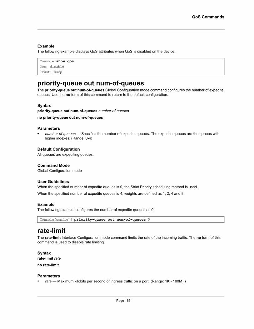
QoS Commands
ExampleThe following example displays QoS attributes when QoS is disabled on the device.
priority-queue out num-of-queuesThe priority-queue out num-of-queues Global Configuration mode command configures the number of expedite queues. Use the no form of this command to return to the default configuration.
Syntaxpriority-queue out num-of-queues number-of-queues
no priority-queue out num-of-queues
Parameters• number-of-queues — Specifies the number of expedite queues. The expedite queues are the queues with
higher indexes. (Range: 0-4)
Default ConfigurationAll queues are expediting queues.
Command ModeGlobal Configuration mode
User GuidelinesWhen the specified number of expedite queues is 0, the Strict Priority scheduling method is used.
When the specified number of expedite queues is 4, weights are defined as 1, 2, 4 and 8.
ExampleThe following example configures the number of expedite queues as 0.
rate-limitThe rate-limit Interface Configuration mode command limits the rate of the incoming traffic. The no form of this command is used to disable rate limiting.
Syntaxrate-limit rate
no rate-limit
Parameters• rate — Maximum kilobits per second of ingress traffic on a port. (Range: 1K - 100M).)
Console show qosQos: disable
Trust: dscp
Console(config)# priority-queue out num-of-queues 0
Page 165
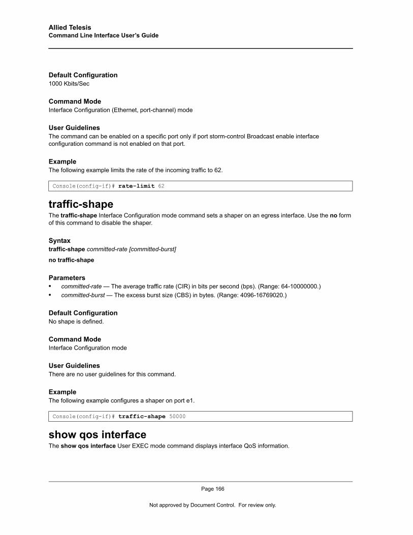
Allied Telesis Command Line Interface User’s Guide
Default Configuration1000 Kbits/Sec
Command ModeInterface Configuration (Ethernet, port-channel) mode
User GuidelinesThe command can be enabled on a specific port only if port storm-control Broadcast enable interface configuration command is not enabled on that port.
ExampleThe following example limits the rate of the incoming traffic to 62.
traffic-shapeThe traffic-shape Interface Configuration mode command sets a shaper on an egress interface. Use the no form of this command to disable the shaper.
Syntaxtraffic-shape committed-rate [committed-burst]
no traffic-shape
Parameters• committed-rate — The average traffic rate (CIR) in bits per second (bps). (Range: 64-10000000.)• committed-burst — The excess burst size (CBS) in bytes. (Range: 4096-16769020.)
Default ConfigurationNo shape is defined.
Command ModeInterface Configuration mode
User GuidelinesThere are no user guidelines for this command.
ExampleThe following example configures a shaper on port e1.
show qos interfaceThe show qos interface User EXEC mode command displays interface QoS information.
Console(config-if)# rate-limit 62
Console(config-if)# traffic-shape 50000
Page 166
Not approved by Document Control. For review only.
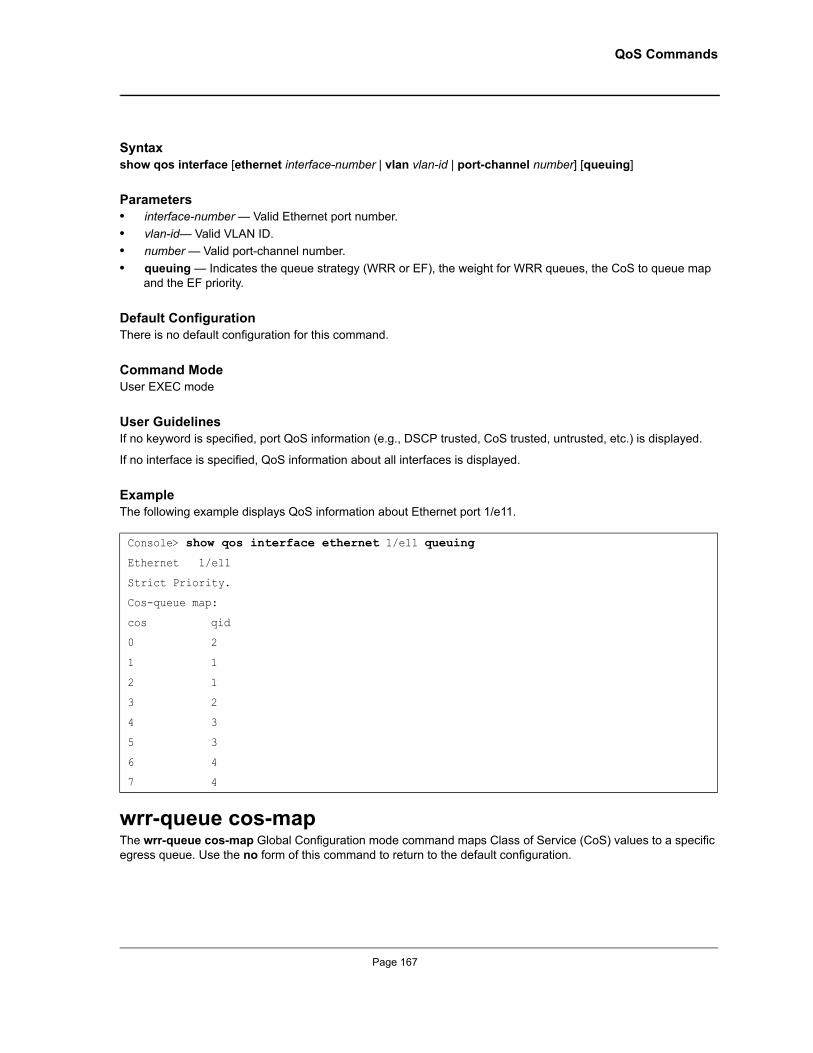
QoS Commands
Syntaxshow qos interface [ethernet interface-number | vlan vlan-id | port-channel number] [queuing]
Parameters• interface-number — Valid Ethernet port number.• vlan-id— Valid VLAN ID.• number — Valid port-channel number.• queuing — Indicates the queue strategy (WRR or EF), the weight for WRR queues, the CoS to queue map
and the EF priority.
Default ConfigurationThere is no default configuration for this command.
Command ModeUser EXEC mode
User GuidelinesIf no keyword is specified, port QoS information (e.g., DSCP trusted, CoS trusted, untrusted, etc.) is displayed.
If no interface is specified, QoS information about all interfaces is displayed.
ExampleThe following example displays QoS information about Ethernet port 1/e11.
wrr-queue cos-mapThe wrr-queue cos-map Global Configuration mode command maps Class of Service (CoS) values to a specific egress queue. Use the no form of this command to return to the default configuration.
Console> show qos interface ethernet 1/e11 queuing
Ethernet 1/e11
Strict Priority.
Cos-queue map:
cos qid
0 2
1 1
2 1
3 2
4 3
5 3
6 4
7 4
Page 167
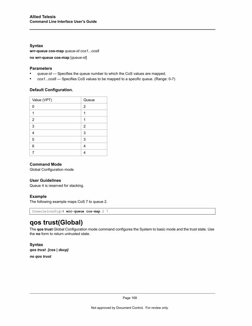
Allied Telesis Command Line Interface User’s Guide
Syntaxwrr-queue cos-map queue-id cos1...cos8
no wrr-queue cos-map [queue-id]
Parameters• queue-id — Specifies the queue number to which the CoS values are mapped.• cos1...cos8 — Specifies CoS values to be mapped to a specific queue. (Range: 0-7)
Default Configuration.
Command ModeGlobal Configuration mode
User GuidelinesQueue 4 is reserved for stacking.
ExampleThe following example maps CoS 7 to queue 2.
qos trust(Global)The qos trust Global Configuration mode command configures the System to basic mode and the trust state. Use the no form to return untrusted state.
Syntaxqos trust {cos | dscp}
no qos trust
Value (VPT) Queue
0 2
1 1
2 1
3 2
4 3
5 3
6 4
7 4
Console(config)# wrr-queue cos-map 2 7
Page 168
Not approved by Document Control. For review only.
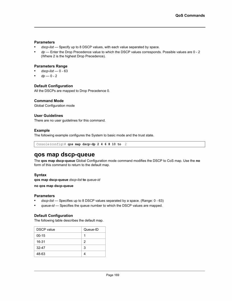
QoS Commands
Parameters• dscp-list — Specify up to 8 DSCP values, with each value separated by space.• dp — Enter the Drop Precedence value to which the DSCP values corresponds. Possible values are 0 - 2
(Where 2 is the highest Drop Precedence).
Parameters Range• dscp-list — 0 - 63• dp — 0 - 2
Default ConfigurationAll the DSCPs are mapped to Drop Precedence 0.
Command ModeGlobal Configuration mode
User GuidelinesThere are no user guidelines for this command.
ExampleThe following example configures the System to basic mode and the trust state.
qos map dscp-queueThe qos map dscp-queue Global Configuration mode command modifies the DSCP to CoS map. Use the no form of this command to return to the default map.
Syntaxqos map dscp-queue dscp-list to queue-id
no qos map dscp-queue
Parameters• dscp-list — Specifies up to 8 DSCP values separated by a space. (Range: 0 - 63)• queue-id — Specifies the queue number to which the DSCP values are mapped.
Default ConfigurationThe following table describes the default map.
Console(config)# qos map dscp-dp 2 4 6 8 10 to 2
DSCP value Queue-ID
00-15 1
16-31 2
32-47 3
48-63 4
Page 169

Allied Telesis Command Line Interface User’s Guide
Command ModeGlobal Configuration mode
User GuidelinesThere are no user guidelines for this command.
ExampleThe following example maps DSCP values 33, 40 and 41 to queue 1.
qos cosThe qos cos Interface Configuration (Ethernet, port-channel) mode command defines the default CoS value of a port. Use the no form of this command to return to the default configuration.
Syntaxqos cos default-cos
no qos cos
Parameters• default-cos — Specifies the default CoS value of the port. (Range: 0 - 7)
Default ConfigurationDefault CoS value of a port is 0.
Command ModeInterface Configuration (Ethernet, port-channel) mode
User GuidelinesIf the port is trusted, the default CoS value of the port is used to assign a CoS value to all untagged packets entering the port.
ExampleThe following example configures port 1/e15 default CoS value to 3.
show qos mapThe show qos map User EXEC mode command displays all QoS maps.
Syntaxshow qos map [dscp-queue]
Console(config)# qos map dscp-queue 33 40 41 to 1
Console(config)# interface ethernet 1/e15Console(config-if) qos cos 3
Page 170
Not approved by Document Control. For review only.
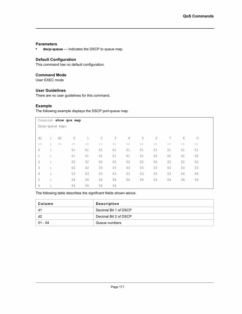
QoS Commands
Parameters• dscp-queue — Indicates the DSCP to queue map.
Default ConfigurationThis command has no default configuration.
Command ModeUser EXEC mode
User GuidelinesThere are no user guidelines for this command.
ExampleThe following example displays the DSCP port-queue map.
The following table describes the significant fields shown above.
Console> show qos map
Dscp-queue map:
d1 : d2 0 1 2 3 4 5 6 7 8 9
-- : -- -- -- -- -- -- -- -- -- -- --
0 : 01 01 01 01 01 01 01 01 01 01
1 : 01 01 01 01 01 01 02 02 02 02
2 : 02 02 02 02 02 02 02 02 02 02
3 : 02 02 03 03 03 03 03 03 03 03
4 : 03 03 03 03 03 03 03 03 04 04
5 : 04 04 04 04 04 04 04 04 04 04
6 : 04 04 04 04
Column Description
d1 Decimal Bit 1 of DSCP
d2 Decimal Bit 2 of DSCP
01 - 04 Queue numbers
Page 171
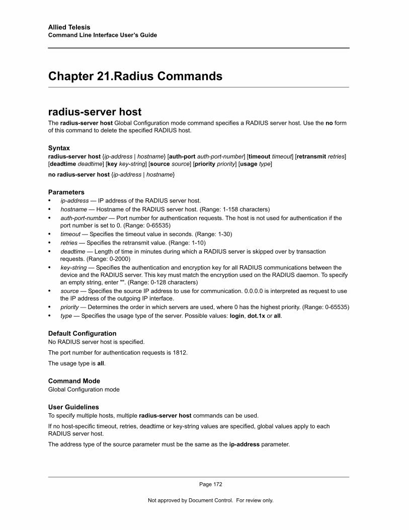
Allied Telesis Command Line Interface User’s Guide
Chapter 21.Radius Commands
radius-server hostThe radius-server host Global Configuration mode command specifies a RADIUS server host. Use the no form of this command to delete the specified RADIUS host.
Syntaxradius-server host {ip-address | hostname} [auth-port auth-port-number] [timeout timeout] [retransmit retries] [deadtime deadtime] [key key-string] [source source] [priority priority] [usage type]
no radius-server host {ip-address | hostname}
Parameters• ip-address — IP address of the RADIUS server host. • hostname — Hostname of the RADIUS server host. (Range: 1-158 characters)• auth-port-number — Port number for authentication requests. The host is not used for authentication if the
port number is set to 0. (Range: 0-65535)• timeout — Specifies the timeout value in seconds. (Range: 1-30)• retries — Specifies the retransmit value. (Range: 1-10)• deadtime — Length of time in minutes during which a RADIUS server is skipped over by transaction
requests. (Range: 0-2000)• key-string — Specifies the authentication and encryption key for all RADIUS communications between the
device and the RADIUS server. This key must match the encryption used on the RADIUS daemon. To specify an empty string, enter "". (Range: 0-128 characters)
• source — Specifies the source IP address to use for communication. 0.0.0.0 is interpreted as request to use the IP address of the outgoing IP interface.
• priority — Determines the order in which servers are used, where 0 has the highest priority. (Range: 0-65535)• type — Specifies the usage type of the server. Possible values: login, dot.1x or all.
Default ConfigurationNo RADIUS server host is specified.
The port number for authentication requests is 1812.
The usage type is all.
Command ModeGlobal Configuration mode
User GuidelinesTo specify multiple hosts, multiple radius-server host commands can be used.
If no host-specific timeout, retries, deadtime or key-string values are specified, global values apply to each RADIUS server host.
The address type of the source parameter must be the same as the ip-address parameter.
Page 172
Not approved by Document Control. For review only.
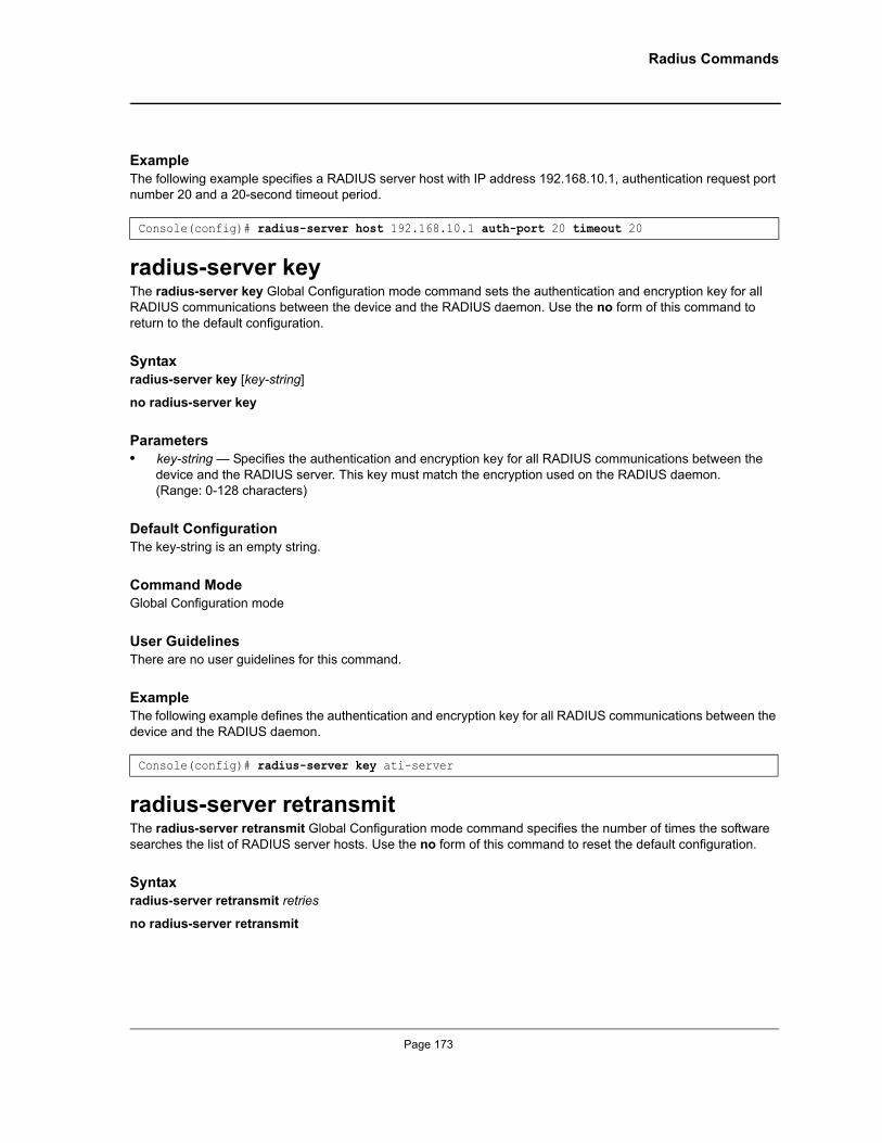
Radius Commands
ExampleThe following example specifies a RADIUS server host with IP address 192.168.10.1, authentication request port number 20 and a 20-second timeout period.
radius-server keyThe radius-server key Global Configuration mode command sets the authentication and encryption key for all RADIUS communications between the device and the RADIUS daemon. Use the no form of this command to return to the default configuration.
Syntaxradius-server key [key-string]
no radius-server key
Parameters• key-string — Specifies the authentication and encryption key for all RADIUS communications between the
device and the RADIUS server. This key must match the encryption used on the RADIUS daemon. (Range: 0-128 characters)
Default ConfigurationThe key-string is an empty string.
Command ModeGlobal Configuration mode
User GuidelinesThere are no user guidelines for this command.
ExampleThe following example defines the authentication and encryption key for all RADIUS communications between the device and the RADIUS daemon.
radius-server retransmitThe radius-server retransmit Global Configuration mode command specifies the number of times the software searches the list of RADIUS server hosts. Use the no form of this command to reset the default configuration.
Syntaxradius-server retransmit retries
no radius-server retransmit
Console(config)# radius-server host 192.168.10.1 auth-port 20 timeout 20
Console(config)# radius-server key ati-server
Page 173
Allied Telesis Command Line Interface User’s Guide
Parameters• retries — Specifies the retransmit value. (Range: 1 - 10)
Default ConfigurationThe software searches the list of RADIUS server hosts 3 times.
Command ModeGlobal Configuration mode
User GuidelinesThere are no user guidelines for this command.
ExampleThe following example configures the number of times the software searches the list of RADIUS server hosts to 5 times.
radius-server source-ipThe radius-server source-ip Global Configuration mode command specifies the source IP address used for communication with RADIUS servers. Use the no form of this command to return to the default configuration.
Syntaxradius-server source-ip source
no radius-source-ip source
Parameters• source — Specifies a valid source IP address.
Default ConfigurationThe source IP address is the IP address of the outgoing IP interface.
Command ModeGlobal Configuration mode
User GuidelinesN/A
ExampleThe following example configures the source IP address used for communication with RADIUS servers to 10.1.1.1.
console(config)# radius-server retransmit 5
console(config)# radius-server source-ip 10.1.1.1
Page 174
Not approved by Document Control. For review only.
Radius Commands
radius-server timeoutThe radius-server timeout Global Configuration mode command sets the interval during which the device waits for a server host to reply. Use the no form of this command to return to the default configuration.
Syntaxradius-server timeout timeout
no radius-server timeout
Parameters• timeout — Specifies the timeout value in seconds. (Range: 1 - 30)
Default ConfigurationThe timeout value is 3 seconds.
Command ModeGlobal Configuration mode
User GuidelinesThere are no user guidelines for this command.
ExampleThe following example configures the timeout interval to 5 seconds.
radius-server deadtimeThe radius-server deadtime Global Configuration mode command improves RADIUS response time when servers are unavailable. The command is used to cause the unavailable servers to be skipped. Use the no form of this command to return to the default configuration.
Syntaxradius-server deadtime deadtime
no radius-server deadtime
Parameters• deadtime — Length of time in minutes during which a RADIUS server is skipped over by transaction
requests. (Range: 0 - 2000)
Default ConfigurationThe deadtime setting is 0.
Command ModeGlobal Configuration mode
Console(config)# radius-server timeout 5
Page 175
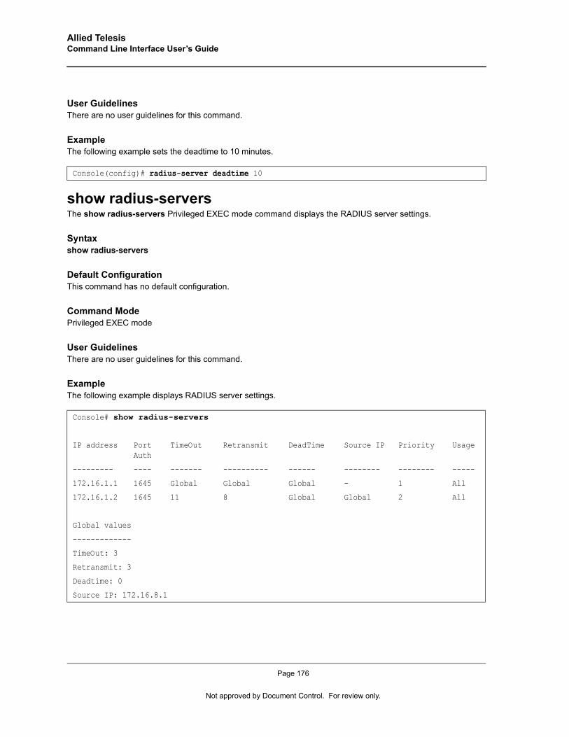
Allied Telesis Command Line Interface User’s Guide
User GuidelinesThere are no user guidelines for this command.
ExampleThe following example sets the deadtime to 10 minutes.
show radius-serversThe show radius-servers Privileged EXEC mode command displays the RADIUS server settings.
Syntaxshow radius-servers
Default ConfigurationThis command has no default configuration.
Command ModePrivileged EXEC mode
User GuidelinesThere are no user guidelines for this command.
ExampleThe following example displays RADIUS server settings.
Console(config)# radius-server deadtime 10
Console# show radius-servers
IP address Port Auth
TimeOut Retransmit DeadTime Source IP Priority Usage
--------- ---- ------- ---------- ------ -------- -------- -----
172.16.1.1 1645 Global Global Global - 1 All
172.16.1.2 1645 11 8 Global Global 2 All
Global values
-------------
TimeOut: 3
Retransmit: 3
Deadtime: 0
Source IP: 172.16.8.1
Page 176
Not approved by Document Control. For review only.
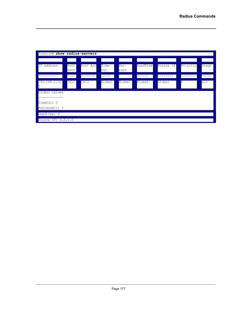
Radius Commands
Console# show radius-servers
IP address Port Auth
Port Acc Time-out
Ret-rans
DeadTime Source IP Priority Usage
--------- ---- ------- ----- ------ -------- -------- -----
192.168.1.101
1812 1813 Global Global Global Global 0 all
Global values
-------------
TimeOut: 3Retransmit: 3
Deadtime: 0
Source IP: 0.0.0.0
Page 177
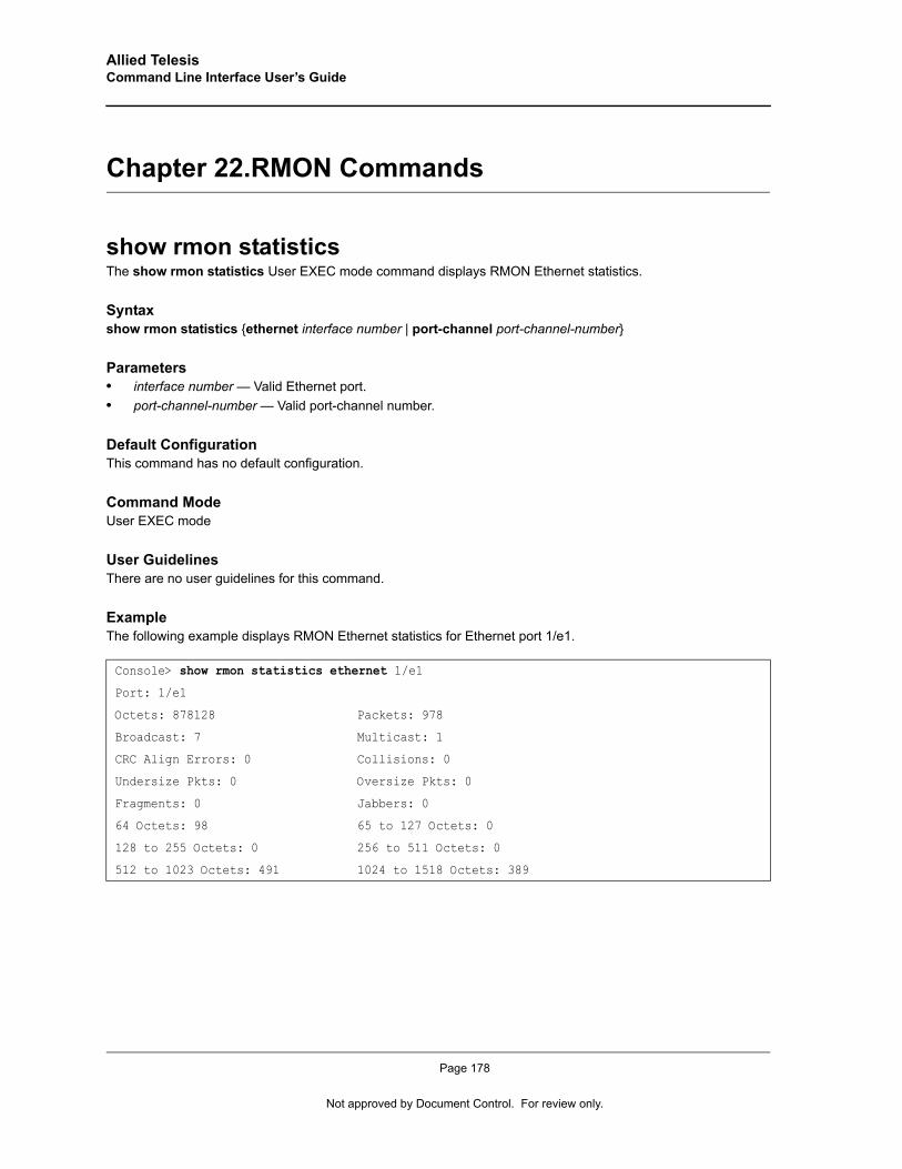
Allied Telesis Command Line Interface User’s Guide
Chapter 22.RMON Commands
show rmon statisticsThe show rmon statistics User EXEC mode command displays RMON Ethernet statistics.
Syntaxshow rmon statistics {ethernet interface number | port-channel port-channel-number}
Parameters• interface number — Valid Ethernet port.• port-channel-number — Valid port-channel number.
Default ConfigurationThis command has no default configuration.
Command ModeUser EXEC mode
User GuidelinesThere are no user guidelines for this command.
ExampleThe following example displays RMON Ethernet statistics for Ethernet port 1/e1.
Console> show rmon statistics ethernet 1/e1
Port: 1/e1
Octets: 878128 Packets: 978
Broadcast: 7 Multicast: 1
CRC Align Errors: 0 Collisions: 0
Undersize Pkts: 0 Oversize Pkts: 0
Fragments: 0 Jabbers: 0
64 Octets: 98 65 to 127 Octets: 0
128 to 255 Octets: 0 256 to 511 Octets: 0
512 to 1023 Octets: 491 1024 to 1518 Octets: 389
Page 178
Not approved by Document Control. For review only.
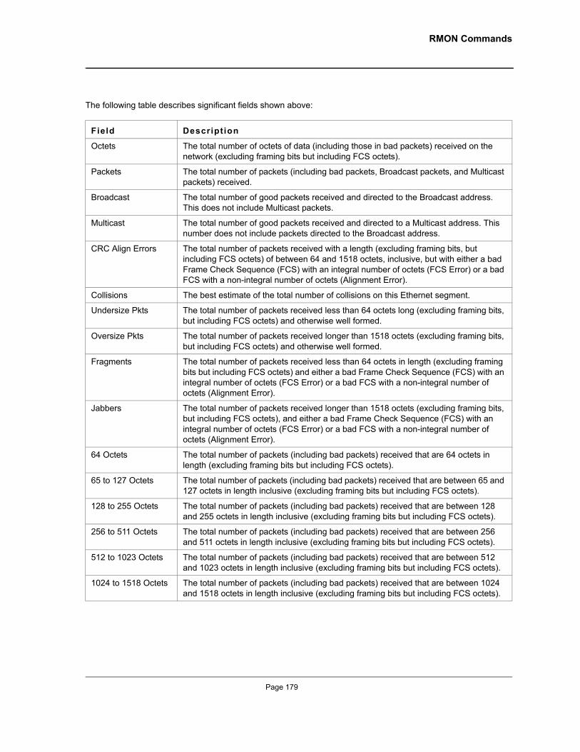
RMON Commands
The following table describes significant fields shown above:
Field Description
Octets The total number of octets of data (including those in bad packets) received on the network (excluding framing bits but including FCS octets).
Packets The total number of packets (including bad packets, Broadcast packets, and Multicast packets) received.
Broadcast The total number of good packets received and directed to the Broadcast address. This does not include Multicast packets.
Multicast The total number of good packets received and directed to a Multicast address. This number does not include packets directed to the Broadcast address.
CRC Align Errors The total number of packets received with a length (excluding framing bits, but including FCS octets) of between 64 and 1518 octets, inclusive, but with either a bad Frame Check Sequence (FCS) with an integral number of octets (FCS Error) or a bad FCS with a non-integral number of octets (Alignment Error).
Collisions The best estimate of the total number of collisions on this Ethernet segment.
Undersize Pkts The total number of packets received less than 64 octets long (excluding framing bits, but including FCS octets) and otherwise well formed.
Oversize Pkts The total number of packets received longer than 1518 octets (excluding framing bits, but including FCS octets) and otherwise well formed.
Fragments The total number of packets received less than 64 octets in length (excluding framing bits but including FCS octets) and either a bad Frame Check Sequence (FCS) with an integral number of octets (FCS Error) or a bad FCS with a non-integral number of octets (Alignment Error).
Jabbers The total number of packets received longer than 1518 octets (excluding framing bits, but including FCS octets), and either a bad Frame Check Sequence (FCS) with an integral number of octets (FCS Error) or a bad FCS with a non-integral number of octets (Alignment Error).
64 Octets The total number of packets (including bad packets) received that are 64 octets in length (excluding framing bits but including FCS octets).
65 to 127 Octets The total number of packets (including bad packets) received that are between 65 and 127 octets in length inclusive (excluding framing bits but including FCS octets).
128 to 255 Octets The total number of packets (including bad packets) received that are between 128 and 255 octets in length inclusive (excluding framing bits but including FCS octets).
256 to 511 Octets The total number of packets (including bad packets) received that are between 256 and 511 octets in length inclusive (excluding framing bits but including FCS octets).
512 to 1023 Octets The total number of packets (including bad packets) received that are between 512 and 1023 octets in length inclusive (excluding framing bits but including FCS octets).
1024 to 1518 Octets The total number of packets (including bad packets) received that are between 1024 and 1518 octets in length inclusive (excluding framing bits but including FCS octets).
Page 179
Allied Telesis Command Line Interface User’s Guide
rmon collection historyThe rmon collection history Interface Configuration (Ethernet, port-channel) mode command enables a Remote Monitoring (RMON) MIB history statistics group on an interface. Use the no form of this command to remove a specified RMON history statistics group.
Syntaxrmon collection history index [owner ownername] [buckets bucket-number] [interval seconds]
no rmon collection history index
Parameters• index — Specifies the statistics group index . (Range: 1-65535)• ownername — Specifies the RMON statistics group owner name. • bucket-number — Number of buckets specified for the RMON collection history group of statistics. If
unspecified, defaults to 50. (Range:1-65535)• seconds — Number of seconds in each polling cycle. (Range: 1-3600)
Default ConfigurationRMON statistics group owner name is an empty string.
Number of buckets specified for the RMON collection history statistics group is 50.
Number of seconds in each polling cycle is 1800.
Command ModeInterface Configuration (Ethernet, port-channel) mode
User GuidelinesCannot be configured for a range of interfaces (range context).
ExampleThe following example enables a Remote Monitoring (RMON) MIB history statistics group on Ethernet port 1/e1 with index number 1 and a polling interval period of 2400 seconds.
show rmon collection historyThe show rmon collection history User EXEC mode command displays the requested RMON history group statistics.
Syntaxshow rmon collection history [ethernet interface | port-channel port-channel-number]
Parameters• interface — Valid Ethernet port. (Full syntax: unit/port)• port-channel-number — Valid port-channel number.
Console(config)# interface ethernet 1/e1Console(config-if)# rmon collection history 1 interval 2400
Page 180
Not approved by Document Control. For review only.
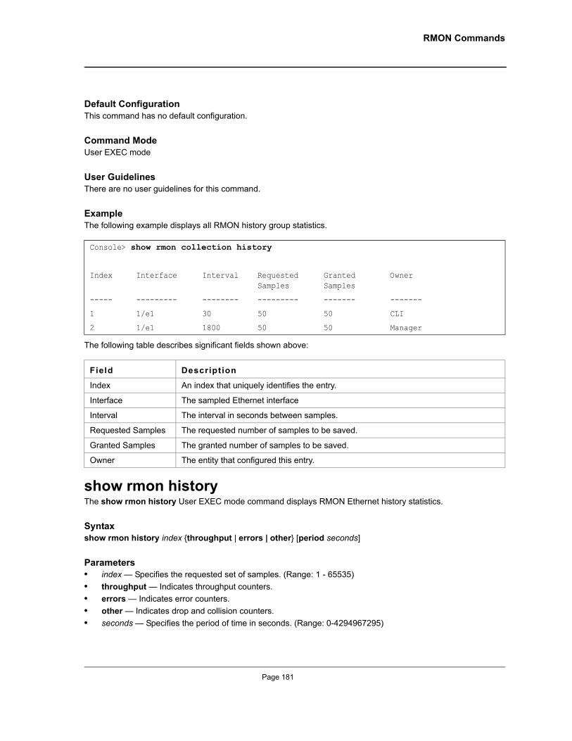
RMON Commands
Default ConfigurationThis command has no default configuration.
Command ModeUser EXEC mode
User GuidelinesThere are no user guidelines for this command.
ExampleThe following example displays all RMON history group statistics.
The following table describes significant fields shown above:
show rmon historyThe show rmon history User EXEC mode command displays RMON Ethernet history statistics.
Syntaxshow rmon history index {throughput | errors | other} [period seconds]
Parameters• index — Specifies the requested set of samples. (Range: 1 - 65535)• throughput — Indicates throughput counters.• errors — Indicates error counters.• other — Indicates drop and collision counters.• seconds — Specifies the period of time in seconds. (Range: 0-4294967295)
Console> show rmon collection history
Index Interface Interval Requested Samples
Granted Samples
Owner
----- --------- -------- --------- ------- -------
1 1/e1 30 50 50 CLI
2 1/e1 1800 50 50 Manager
Field Description
Index An index that uniquely identifies the entry.
Interface The sampled Ethernet interface
Interval The interval in seconds between samples.
Requested Samples The requested number of samples to be saved.
Granted Samples The granted number of samples to be saved.
Owner The entity that configured this entry.
Page 181
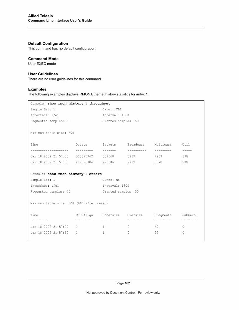
Allied Telesis Command Line Interface User’s Guide
Default ConfigurationThis command has no default configuration.
Command ModeUser EXEC mode
User GuidelinesThere are no user guidelines for this command.
ExamplesThe following examples displays RMON Ethernet history statistics for index 1.
Console> show rmon history 1 throughput
Sample Set: 1 Owner: CLI
Interface: 1/e1 Interval: 1800
Requested samples: 50 Granted samples: 50
Maximum table size: 500
Time Octets Packets Broadcast Multicast Util
-------------------- --------- ------- ---------- --------- -----
Jan 18 2002 21:57:00 303595962 357568 3289 7287 19%
Jan 18 2002 21:57:30 287696304 275686 2789 5878 20%
Console> show rmon history 1 errors
Sample Set: 1 Owner: Me
Interface: 1/e1 Interval: 1800
Requested samples: 50 Granted samples: 50
Maximum table size: 500 (800 after reset)
Time CRC Align Undersize Oversize Fragments Jabbers
---------- --------- --------- -------- --------- -------
Jan 18 2002 21:57:00 1 1 0 49 0
Jan 18 2002 21:57:30 1 1 0 27 0
Page 182
Not approved by Document Control. For review only.
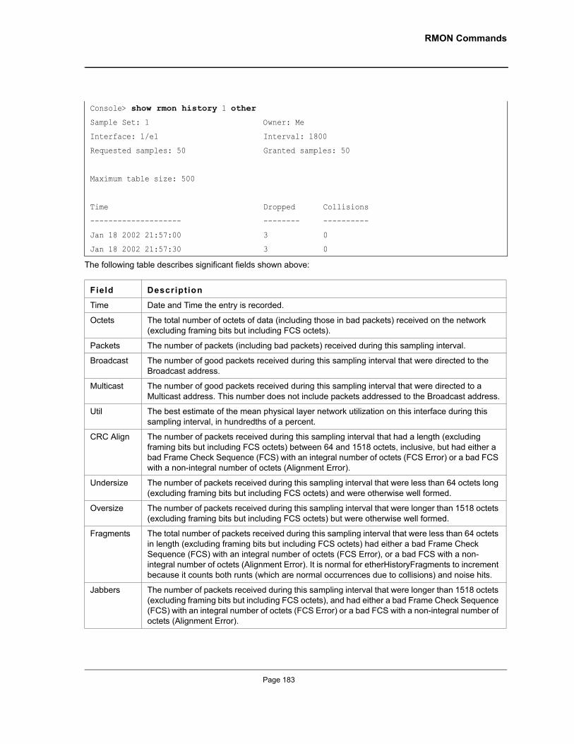
RMON Commands
The following table describes significant fields shown above:
Console> show rmon history 1 other
Sample Set: 1 Owner: Me
Interface: 1/e1 Interval: 1800
Requested samples: 50 Granted samples: 50
Maximum table size: 500
Time Dropped Collisions
-------------------- -------- ----------
Jan 18 2002 21:57:00 3 0
Jan 18 2002 21:57:30 3 0
Field Description
Time Date and Time the entry is recorded.
Octets The total number of octets of data (including those in bad packets) received on the network (excluding framing bits but including FCS octets).
Packets The number of packets (including bad packets) received during this sampling interval.
Broadcast The number of good packets received during this sampling interval that were directed to the Broadcast address.
Multicast The number of good packets received during this sampling interval that were directed to a Multicast address. This number does not include packets addressed to the Broadcast address.
Util The best estimate of the mean physical layer network utilization on this interface during this sampling interval, in hundredths of a percent.
CRC Align The number of packets received during this sampling interval that had a length (excluding framing bits but including FCS octets) between 64 and 1518 octets, inclusive, but had either a bad Frame Check Sequence (FCS) with an integral number of octets (FCS Error) or a bad FCS with a non-integral number of octets (Alignment Error).
Undersize The number of packets received during this sampling interval that were less than 64 octets long (excluding framing bits but including FCS octets) and were otherwise well formed.
Oversize The number of packets received during this sampling interval that were longer than 1518 octets (excluding framing bits but including FCS octets) but were otherwise well formed.
Fragments The total number of packets received during this sampling interval that were less than 64 octets in length (excluding framing bits but including FCS octets) had either a bad Frame Check Sequence (FCS) with an integral number of octets (FCS Error), or a bad FCS with a non-integral number of octets (Alignment Error). It is normal for etherHistoryFragments to increment because it counts both runts (which are normal occurrences due to collisions) and noise hits.
Jabbers The number of packets received during this sampling interval that were longer than 1518 octets (excluding framing bits but including FCS octets), and had either a bad Frame Check Sequence (FCS) with an integral number of octets (FCS Error) or a bad FCS with a non-integral number of octets (Alignment Error).
Page 183
Allied Telesis Command Line Interface User’s Guide
rmon alarmThe rmon alarm Global Configuration mode command configures alarm conditions. Use the no form of this command to remove an alarm.
Syntaxrmon alarm index variable interval rthreshold fthreshold revent fevent [type type] [startup direction] [owner name]
no rmon alarm index
Parameters• index — Specifies the alarm index. (Range: 1-65535)• variable — Specifies the object identifier of the variable to be sampled. • interval — Specifies the interval in seconds during which the data is sampled and compared with rising and
falling thresholds. (Range: 1-2147483647)• rthreshold — Specifies the rising threshold. (Range: 0-2147483647)• fthreshold — Specifies the falling threshold. (Range: 0-2147483647)• revent — Specifies the event index used when a rising threshold is crossed.
(Range: 1-65535)• fevent — Specifies the event index used when a falling threshold is crossed.
(Range: 1-65535)• type — Specifies the method used for sampling the selected variable and calculating the value to be
compared against the thresholds. Possible values are absolute and delta. If the method is absolute, the value of the selected variable is compared directly with the thresholds at the end of the sampling interval. If the method is delta, the selected variable value of the last sample is subtracted from the current value, and the difference is compared with the thresholds.
• direction — Specifies the alarm that may be sent when this entry is first set to valid. Possible values are rising, rising-falling and falling.If the first sample (after this entry becomes valid) is greater than or equal to rthreshold and direction is equal to rising or rising-falling, a single rising alarm is generated. If the first sample (after this entry becomes valid) is less than or equal to fthreshold and direction is equal to falling or rising-falling, a single falling alarm is generated.
• name — Specifies the name of the person who configured this alarm. If unspecified, the name is an empty string.
Default ConfigurationThe type is absolute.
The startup direction is rising-falling.
Dropped The total number of events in which packets were dropped by the probe due to lack of resources during this sampling interval. This number is not necessarily the number of packets dropped, it is just the number of times this condition has been detected.
Collisions The best estimate of the total number of collisions on this Ethernet segment during this sampling interval.
Page 184
Not approved by Document Control. For review only.
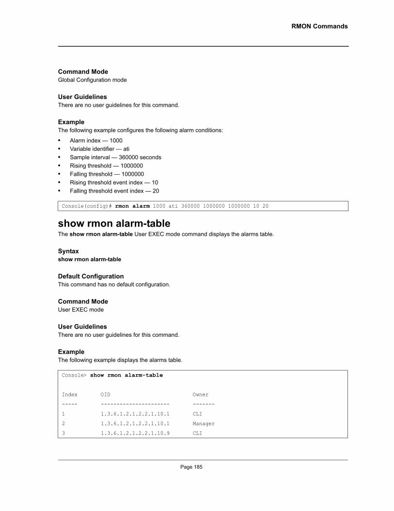
RMON Commands
Command ModeGlobal Configuration mode
User GuidelinesThere are no user guidelines for this command.
ExampleThe following example configures the following alarm conditions:
• Alarm index — 1000• Variable identifier — ati• Sample interval — 360000 seconds• Rising threshold — 1000000• Falling threshold — 1000000• Rising threshold event index — 10• Falling threshold event index — 20
show rmon alarm-tableThe show rmon alarm-table User EXEC mode command displays the alarms table.
Syntaxshow rmon alarm-table
Default ConfigurationThis command has no default configuration.
Command ModeUser EXEC mode
User GuidelinesThere are no user guidelines for this command.
ExampleThe following example displays the alarms table.
Console(config)# rmon alarm 1000 ati 360000 1000000 1000000 10 20
Console> show rmon alarm-table
Index OID Owner
----- ---------------------- -------
1 1.3.6.1.2.1.2.2.1.10.1 CLI
2 1.3.6.1.2.1.2.2.1.10.1 Manager
3 1.3.6.1.2.1.2.2.1.10.9 CLI
Page 185
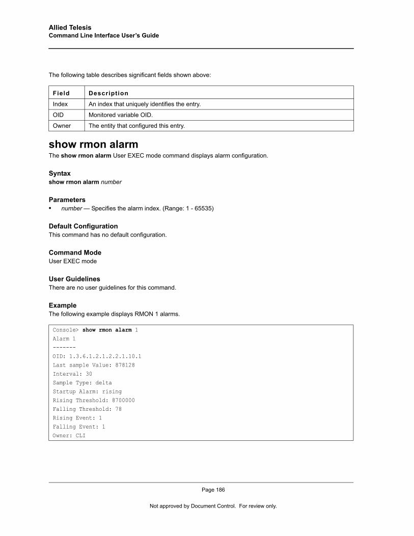
Allied Telesis Command Line Interface User’s Guide
The following table describes significant fields shown above:
show rmon alarmThe show rmon alarm User EXEC mode command displays alarm configuration.
Syntaxshow rmon alarm number
Parameters• number — Specifies the alarm index. (Range: 1 - 65535)
Default ConfigurationThis command has no default configuration.
Command ModeUser EXEC mode
User GuidelinesThere are no user guidelines for this command.
ExampleThe following example displays RMON 1 alarms.
Field Description
Index An index that uniquely identifies the entry.
OID Monitored variable OID.
Owner The entity that configured this entry.
Console> show rmon alarm 1Alarm 1
-------OID: 1.3.6.1.2.1.2.2.1.10.1
Last sample Value: 878128
Interval: 30Sample Type: delta
Startup Alarm: rising
Rising Threshold: 8700000Falling Threshold: 78
Rising Event: 1
Falling Event: 1Owner: CLI
Page 186
Not approved by Document Control. For review only.
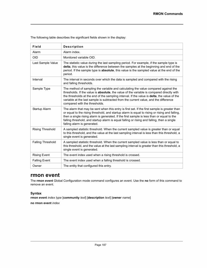
RMON Commands
The following table describes the significant fields shown in the display:
rmon eventThe rmon event Global Configuration mode command configures an event. Use the no form of this command to remove an event.
Syntaxrmon event index type [community text] [description text] [owner name]
no rmon event index
Field Description
Alarm Alarm index.
OID Monitored variable OID.
Last Sample Value The statistic value during the last sampling period. For example, if the sample type is delta, this value is the difference between the samples at the beginning and end of the period. If the sample type is absolute, this value is the sampled value at the end of the period.
Interval The interval in seconds over which the data is sampled and compared with the rising and falling thresholds.
Sample Type The method of sampling the variable and calculating the value compared against the thresholds. If the value is absolute, the value of the variable is compared directly with the thresholds at the end of the sampling interval. If the value is delta, the value of the variable at the last sample is subtracted from the current value, and the difference compared with the thresholds.
Startup Alarm The alarm that may be sent when this entry is first set. If the first sample is greater than or equal to the rising threshold, and startup alarm is equal to rising or rising and falling, then a single rising alarm is generated. If the first sample is less than or equal to the falling threshold, and startup alarm is equal falling or rising and falling, then a single falling alarm is generated.
Rising Threshold A sampled statistic threshold. When the current sampled value is greater than or equal to this threshold, and the value at the last sampling interval is less than this threshold, a single event is generated.
Falling Threshold A sampled statistic threshold. When the current sampled value is less than or equal to this threshold, and the value at the last sampling interval is greater than this threshold, a single event is generated.
Rising Event The event index used when a rising threshold is crossed.
Falling Event The event index used when a falling threshold is crossed.
Owner The entity that configured this entry.
Page 187
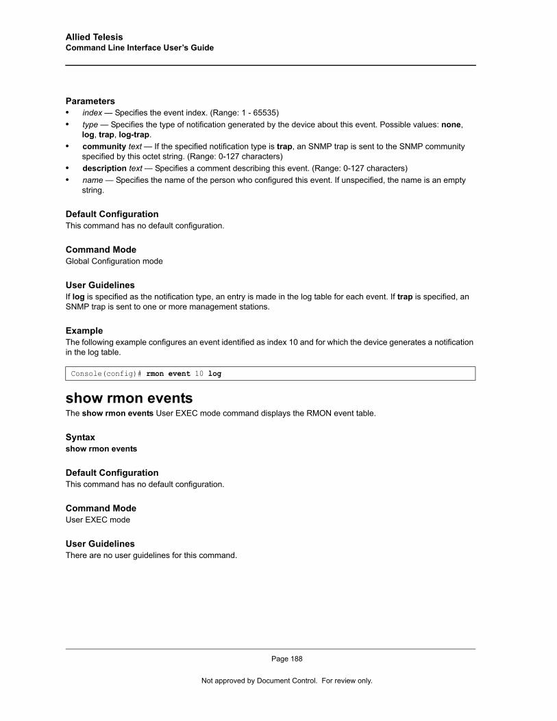
Allied Telesis Command Line Interface User’s Guide
Parameters• index — Specifies the event index. (Range: 1 - 65535)• type — Specifies the type of notification generated by the device about this event. Possible values: none,
log, trap, log-trap.• community text — If the specified notification type is trap, an SNMP trap is sent to the SNMP community
specified by this octet string. (Range: 0-127 characters)• description text — Specifies a comment describing this event. (Range: 0-127 characters)• name — Specifies the name of the person who configured this event. If unspecified, the name is an empty
string.
Default ConfigurationThis command has no default configuration.
Command ModeGlobal Configuration mode
User GuidelinesIf log is specified as the notification type, an entry is made in the log table for each event. If trap is specified, an SNMP trap is sent to one or more management stations.
ExampleThe following example configures an event identified as index 10 and for which the device generates a notification in the log table.
show rmon eventsThe show rmon events User EXEC mode command displays the RMON event table.
Syntaxshow rmon events
Default ConfigurationThis command has no default configuration.
Command ModeUser EXEC mode
User GuidelinesThere are no user guidelines for this command.
Console(config)# rmon event 10 log
Page 188
Not approved by Document Control. For review only.
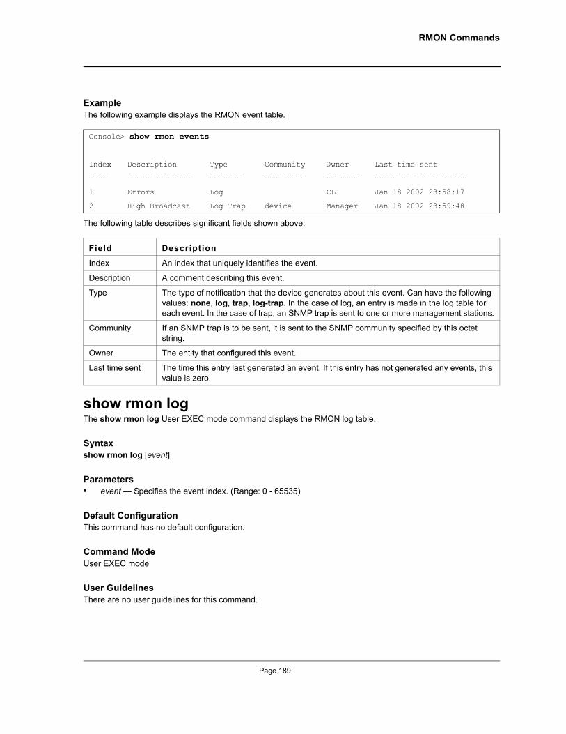
RMON Commands
ExampleThe following example displays the RMON event table.
The following table describes significant fields shown above:
show rmon logThe show rmon log User EXEC mode command displays the RMON log table.
Syntaxshow rmon log [event]
Parameters• event — Specifies the event index. (Range: 0 - 65535)
Default ConfigurationThis command has no default configuration.
Command ModeUser EXEC mode
User GuidelinesThere are no user guidelines for this command.
Console> show rmon events
Index Description Type Community Owner Last time sent
----- -------------- -------- --------- ------- --------------------
1 Errors Log CLI Jan 18 2002 23:58:17
2 High Broadcast Log-Trap device Manager Jan 18 2002 23:59:48
Field Description
Index An index that uniquely identifies the event.
Description A comment describing this event.
Type The type of notification that the device generates about this event. Can have the following values: none, log, trap, log-trap. In the case of log, an entry is made in the log table for each event. In the case of trap, an SNMP trap is sent to one or more management stations.
Community If an SNMP trap is to be sent, it is sent to the SNMP community specified by this octet string.
Owner The entity that configured this event.
Last time sent The time this entry last generated an event. If this entry has not generated any events, this value is zero.
Page 189
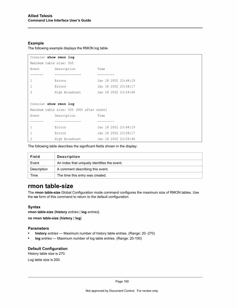
Allied Telesis Command Line Interface User’s Guide
ExampleThe following example displays the RMON log table.
The following table describes the significant fields shown in the display:
rmon table-sizeThe rmon table-size Global Configuration mode command configures the maximum size of RMON tables. Use the no form of this command to return to the default configuration.
Syntaxrmon table-size {history entries | log entries}
no rmon table-size {history | log}
Parameters• history entries — Maximum number of history table entries. (Range: 20 -270)• log entries — Maximum number of log table entries. (Range: 20-100)
Default ConfigurationHistory table size is 270.
Log table size is 200.
Console> show rmon log
Maximum table size: 500
Event Description Time
------- -------------- ---------
1 Errors Jan 18 2002 23:48:19
1 Errors Jan 18 2002 23:58:17
2 High Broadcast Jan 18 2002 23:59:48
Console> show rmon log
Maximum table size: 500 (800 after reset)
Event Description Time
------- -------------- ---------
1 Errors Jan 18 2002 23:48:19
1 Errors Jan 18 2002 23:58:17
2 High Broadcast Jan 18 2002 23:59:48
Field Description
Event An index that uniquely identifies the event.
Description A comment describing this event.
Time The time this entry was created.
Page 190
Not approved by Document Control. For review only.
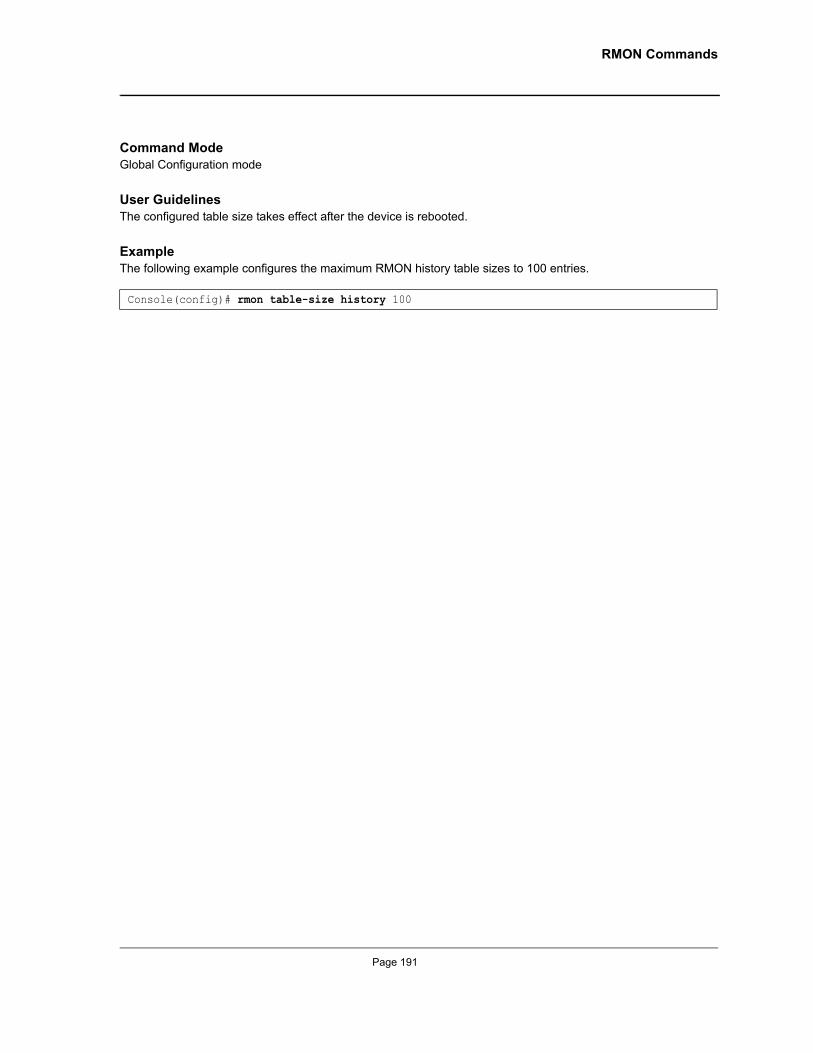
RMON Commands
Command ModeGlobal Configuration mode
User GuidelinesThe configured table size takes effect after the device is rebooted.
ExampleThe following example configures the maximum RMON history table sizes to 100 entries.
Console(config)# rmon table-size history 100
Page 191
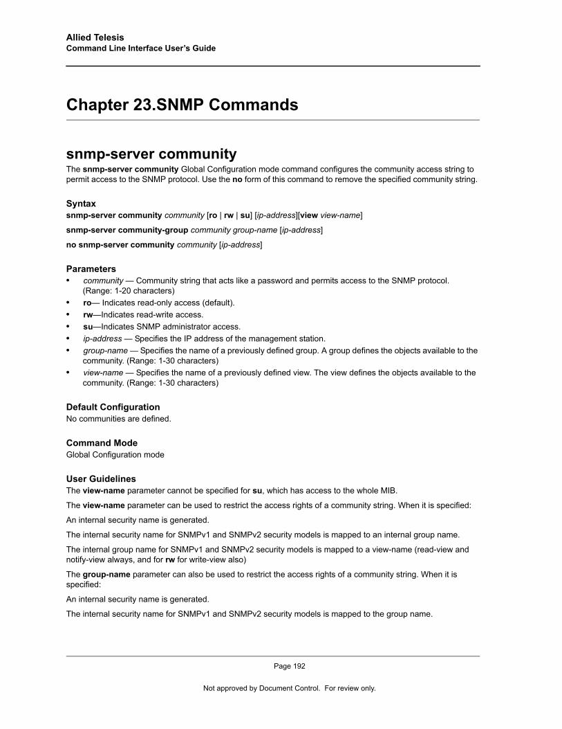
Allied Telesis Command Line Interface User’s Guide
Chapter 23.SNMP Commands
snmp-server communityThe snmp-server community Global Configuration mode command configures the community access string to permit access to the SNMP protocol. Use the no form of this command to remove the specified community string.
Syntaxsnmp-server community community [ro | rw | su] [ip-address][view view-name]
snmp-server community-group community group-name [ip-address]
no snmp-server community community [ip-address]
Parameters• community — Community string that acts like a password and permits access to the SNMP protocol.
(Range: 1-20 characters)• ro— Indicates read-only access (default).• rw—Indicates read-write access.• su—Indicates SNMP administrator access.• ip-address — Specifies the IP address of the management station.• group-name — Specifies the name of a previously defined group. A group defines the objects available to the
community. (Range: 1-30 characters)• view-name — Specifies the name of a previously defined view. The view defines the objects available to the
community. (Range: 1-30 characters)
Default ConfigurationNo communities are defined.
Command ModeGlobal Configuration mode
User GuidelinesThe view-name parameter cannot be specified for su, which has access to the whole MIB.
The view-name parameter can be used to restrict the access rights of a community string. When it is specified:
An internal security name is generated.
The internal security name for SNMPv1 and SNMPv2 security models is mapped to an internal group name.
The internal group name for SNMPv1 and SNMPv2 security models is mapped to a view-name (read-view and notify-view always, and for rw for write-view also)
The group-name parameter can also be used to restrict the access rights of a community string. When it is specified:
An internal security name is generated.
The internal security name for SNMPv1 and SNMPv2 security models is mapped to the group name.
Page 192
Not approved by Document Control. For review only.
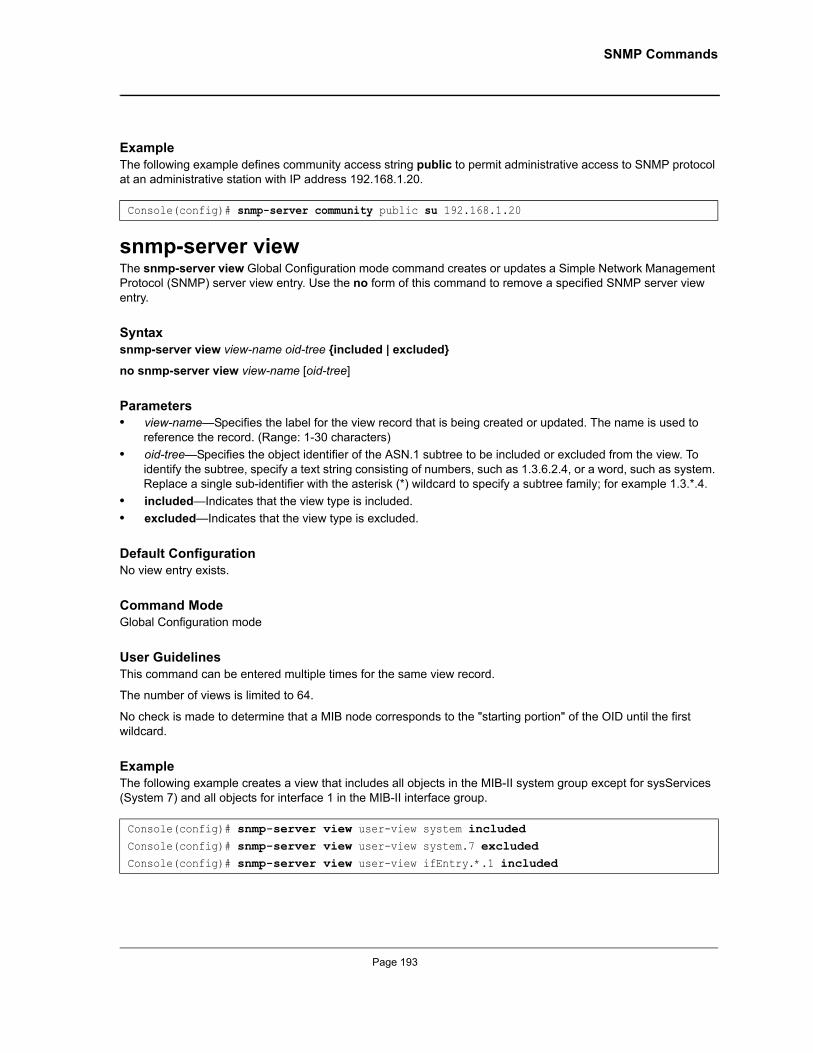
SNMP Commands
ExampleThe following example defines community access string public to permit administrative access to SNMP protocol at an administrative station with IP address 192.168.1.20.
snmp-server viewThe snmp-server view Global Configuration mode command creates or updates a Simple Network Management Protocol (SNMP) server view entry. Use the no form of this command to remove a specified SNMP server view entry.
Syntaxsnmp-server view view-name oid-tree {included | excluded}
no snmp-server view view-name [oid-tree]
Parameters• view-name—Specifies the label for the view record that is being created or updated. The name is used to
reference the record. (Range: 1-30 characters)• oid-tree—Specifies the object identifier of the ASN.1 subtree to be included or excluded from the view. To
identify the subtree, specify a text string consisting of numbers, such as 1.3.6.2.4, or a word, such as system. Replace a single sub-identifier with the asterisk (*) wildcard to specify a subtree family; for example 1.3.*.4.
• included—Indicates that the view type is included.• excluded—Indicates that the view type is excluded.
Default ConfigurationNo view entry exists.
Command ModeGlobal Configuration mode
User GuidelinesThis command can be entered multiple times for the same view record.
The number of views is limited to 64.
No check is made to determine that a MIB node corresponds to the "starting portion" of the OID until the first wildcard.
ExampleThe following example creates a view that includes all objects in the MIB-II system group except for sysServices (System 7) and all objects for interface 1 in the MIB-II interface group.
Console(config)# snmp-server community public su 192.168.1.20
Console(config)# snmp-server view user-view system included Console(config)# snmp-server view user-view system.7 excluded Console(config)# snmp-server view user-view ifEntry.*.1 included
Page 193
Allied Telesis Command Line Interface User’s Guide
snmp-server groupThe snmp-server group Global Configuration mode command configures a new Simple Management Protocol (SNMP) group or a table that maps SNMP users to SNMP views. Use the no form of this command to remove a specified SNMP group.
Syntaxsnmp-server group groupname {v1 | v2 | v3 {noauth | auth | priv} [notify notifyview ] } [read readview] [write writeview]
no snmp-server group groupname {v1 | v2 | v3 [noauth | auth | priv]}
Parameters• groupname—Specifies the name of the group. • v1—Indicates the SNMP Version 1 security model.• v2—Indicates the SNMP Version 2 security model.• v3—Indicates the SNMP Version 3 security model.• noauth—Indicates no authentication of a packet. Applicable only to the SNMP Version 3 security model.• auth—Indicates authentication of a packet without encrypting it. Applicable only to the SNMP Version 3
security model.• priv—Indicates authentication of a packet with encryption. Applicable only to the SNMP Version 3 security
model.• readview—Specifies a string that is the name of the view that enables only viewing the contents of the agent.
If unspecified, all objects except for the community-table and SNMPv3 user and access tables are available.• writeview—Specifies a string that is the name of the view that enables entering data and configuring the
contents of the agent. If unspecified, nothing is defined for the write view.• notifyview—Specifies a string that is the name of the view that enables specifying an inform or a trap. If
unspecified, nothing is defined for the notify view. Applicable only to the SNMP Version 3 security model.
Default ConfigurationNo group entry exists.
Command ModeGlobal Configuration mode
User GuidelinesThere are no user guidelines for this command.
ExampleThe following example attaches a group called user-group to SNMPv3 and assigns to the group the privacy security level and read access rights to a view called user-view.
snmp-server userThe snmp-server user Global Configuration mode command configures a new SNMP Version 3 user. Use the no form of this command to remove a user.
Console(config)# snmp-server group user-group v3 priv read user-view
Page 194
Not approved by Document Control. For review only.
SNMP Commands
Syntaxsnmp-server user username groupname [remote engineid-string] [ auth-md5 password | auth-sha password | auth-md5-key md5-des-keys | auth-sha-key sha-des-keys ]
no snmp-server user username [remote engineid-string]
Parameters• username—Specifies the name of the user on the host that connects to the agent. (Range: 1-30 characters)• groupname—Specifies the name of the group to which the user belongs. (Range: 1-30 characters)• engineid-string—Specifies the engine ID of the remote SNMP entity to which the user belongs. The engine ID
is a concatenated hexadecimal string. Each byte in the hexadecimal character string is two hexadecimal digits. Each byte can be separated by a period or colon. (Range: 5-32 characters)
• auth-md5 password—Indicates the HMAC-MD5-96 authentication level. The user should enter a password for authentication and generation of a DES key for privacy. (Range: 1-32 characters)
• auth-sha password—Indicates the HMAC-SHA-96 authentication level. The user should enter a password for authentication and generation of a DES key for privacy. (Range: 1-32 characters)
• auth-md5-key md5-des-keys—Indicates the HMAC-MD5-96 authentication level. The user should enter a concatenated hexadecimal string of the MD5 key (MSB) and the privacy key (LSB). If authentication is only required, 16 bytes should be entered; if authentication and privacy are required, 32 bytes should be entered. Each byte in the hexadecimal character string is two hexadecimal digits. Each byte can be separated by a period or colon. (16 or 32 bytes)
• auth-sha-key sha-des-keys—Indicates the HMAC-SHA-96 authentication level. The user should enter a concatenated hexadecimal string of the SHA key (MSB) and the privacy key (LSB). If authentication is only required, 20 bytes should be entered; if authentication and privacy are required, 36 bytes should be entered. Each byte in the hexadecimal character string is two hexadecimal digits. Each byte can be separated by a period or colon. (20 or 36 bytes)
Default ConfigurationNo group entry exists.
Command ModeGlobal Configuration mode
User GuidelinesIf auth-md5 or auth-sha is specified, both authentication and privacy are enabled for the user.
When a show running-config Privileged EXEC mode command is entered, a line for this user will not be displayed. To see if this user has been added to the configuration, type the show snmp users Privileged EXEC mode command.
An SNMP EngineID has to be defined to add SNMP users to the device. Changing or removing the SNMP EngineID value deletes SNMPv3 users from the device’s database.
The remote engineid designates the remote management station and should be defined to enable the device to receive informs.
ExampleThe following example configures an SNMPv3 user John in group user-group.
Console(config)# snmp-server user John user-group
Page 195
Allied Telesis Command Line Interface User’s Guide
snmp-server engineID localThe snmp-server engineID local Global Configuration mode command specifies the Simple Network Management Protocol (SNMP) engineID on the local device. Use the no form of this command to remove the configured engine ID.
Syntaxsnmp-server engineID local {engineid-string | default}
no snmp-server engineID local
Parameters• engineid-string—Specifies a character string that identifies the engine ID. (Range: 5-32 characters)• default—The engine ID is created automatically based on the device MAC address.
Default ConfigurationThe engine ID is not configured.
If SNMPv3 is enabled using this command, and the default is specified, the default engine ID is defined per standard as:
• First 4 octets — first bit = 1, the rest is IANA Enterprise number = 674.• Fifth octet — set to 3 to indicate the MAC address that follows.• Last 6 octets — MAC address of the device.
Command ModeGlobal Configuration mode
User GuidelinesTo use SNMPv3, you have to specify an engine ID for the device. You can specify your own ID or use a default string that is generated using the MAC address of the device.
If the SNMPv3 engine ID is deleted or the configuration file is erased, SNMPv3 cannot be used. By default, SNMPv1/v2 are enabled on the device. SNMPv3 is enabled only by defining the Local Engine ID.
If you want to specify your own ID, you do not have to specify the entire 32-character engine ID if it contains trailing zeros. Specify only the portion of the engine ID up to the point where just zeros remain in the value. For example, to configure an engine ID of 123400000000000000000000, you can specify snmp-server engineID local 1234.
Since the engine ID should be unique within an administrative domain, the following is recommended:
For a standalone device, use the default keyword to configure the engine ID.
For a stackable system, configure the engine ID and verify its uniqueness.
Changing the value of the engine ID has the following important side-effect. A user's password (entered on the command line) is converted to an MD5 or SHA security digest. This digest is based on both the password and the local engine ID. The user’s command line password is then destroyed, as required by RFC 2274. As a result, the security digests of SNMPv3 users become invalid if the local value of the engine ID change, and the users will have to be reconfigured.
You cannot specify an engine ID that consists of all 0x0, all 0xF or 0x000000001.
Page 196
Not approved by Document Control. For review only.
SNMP Commands
The show running-config Privileged EXEC mode command does not display the SNMP engine ID configuration. To see the SNMP engine ID configuration, enter the snmp-server engineID local Global Configuration mode command.
ExampleThe following example enables SNMPv3 on the device and sets the local engine ID of the device to the default value.
snmp-server enable trapsThe snmp-server enable traps Global Configuration mode command enables the device to send SNMP traps. Use the no form of this command to disable SNMP traps.
Syntaxsnmp-server enable traps
no snmp-server enable traps
Default ConfigurationSNMP traps are enabled.
Command ModeGlobal Configuration mode
User GuidelinesThere are no user guidelines for this command.
ExampleThe following example enables SNMP traps.
snmp-server filterThe snmp-server filter Global Configuration mode command creates or updates a Simple Network Management Protocol (SNMP) server filter entry. Use the no form of this command to remove the specified SNMP server filter entry.
Syntaxsnmp-server filter filter-name oid-tree {included | excluded}
no snmp-server filter filter-name [oid-tree]
Console(config) # snmp-server engineID local default
Console(config)# snmp-server enable traps
Page 197
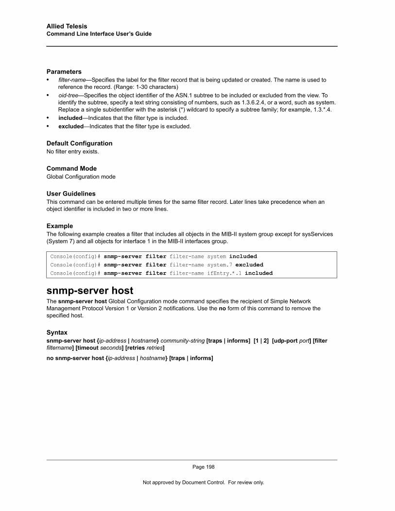
Allied Telesis Command Line Interface User’s Guide
Parameters• filter-name—Specifies the label for the filter record that is being updated or created. The name is used to
reference the record. (Range: 1-30 characters)• oid-tree—Specifies the object identifier of the ASN.1 subtree to be included or excluded from the view. To
identify the subtree, specify a text string consisting of numbers, such as 1.3.6.2.4, or a word, such as system. Replace a single subidentifier with the asterisk (*) wildcard to specify a subtree family; for example, 1.3.*.4.
• included—Indicates that the filter type is included.• excluded—Indicates that the filter type is excluded.
Default ConfigurationNo filter entry exists.
Command ModeGlobal Configuration mode
User GuidelinesThis command can be entered multiple times for the same filter record. Later lines take precedence when an object identifier is included in two or more lines.
ExampleThe following example creates a filter that includes all objects in the MIB-II system group except for sysServices (System 7) and all objects for interface 1 in the MIB-II interfaces group.
snmp-server hostThe snmp-server host Global Configuration mode command specifies the recipient of Simple Network Management Protocol Version 1 or Version 2 notifications. Use the no form of this command to remove the specified host.
Syntaxsnmp-server host {ip-address | hostname} community-string [traps | informs] [1 | 2] [udp-port port] [filter filtername] [timeout seconds] [retries retries]
no snmp-server host {ip-address | hostname} [traps | informs]
Console(config)# snmp-server filter filter-name system includedConsole(config)# snmp-server filter filter-name system.7 excludedConsole(config)# snmp-server filter filter-name ifEntry.*.1 included
Page 198
Not approved by Document Control. For review only.
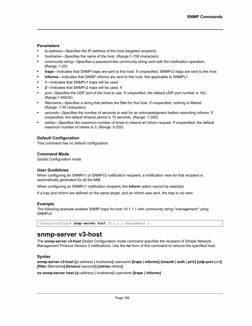
SNMP Commands
Parameters• ip-address—Specifies the IP address of the host (targeted recipient).• hostname—Specifies the name of the host. (Range:1-158 characters)• community-string—Specifies a password-like community string sent with the notification operation.
(Range: 1-20)• traps—Indicates that SNMP traps are sent to this host. If unspecified, SNMPv2 traps are sent to the host.• informs—Indicates that SNMP informs are sent to this host. Not applicable to SNMPv1.• 1—Indicates that SNMPv1 traps will be used.• 2—Indicates that SNMPv2 traps will be used. If • port—Specifies the UDP port of the host to use. If unspecified, the default UDP port number is 162.
(Range:1-65535)• filtername—Specifies a string that defines the filter for this host. If unspecified, nothing is filtered.
(Range: 1-30 characters)• seconds—Specifies the number of seconds to wait for an acknowledgment before resending informs. If
unspecified, the default timeout period is 15 seconds. (Range: 1-300)• retries—Specifies the maximum number of times to resend an inform request. If unspecified, the default
maximum number of retries is 3. (Range: 0-255)
Default ConfigurationThis command has no default configuration.
Command ModeGlobal Configuration mode
User GuidelinesWhen configuring an SNMPv1 or SNMPv2 notification recipient, a notification view for that recipient is automatically generated for all the MIB.
When configuring an SNMPv1 notification recipient, the Inform option cannot be selected.
If a trap and inform are defined on the same target, and an inform was sent, the trap is not sent.
ExampleThe following example enables SNMP traps for host 10.1.1.1 with community string "management" using SNMPv2.
snmp-server v3-hostThe snmp-server v3-host Global Configuration mode command specifies the recipient of Simple Network Management Protocol Version 3 notifications. Use the no form of this command to remove the specified host.
Syntaxsnmp-server v3-host {ip-address | hostname} username [traps | informs] {noauth | auth | priv} [udp-port port] [filter filtername] [timeout seconds] [retries retries]
no snmp-server host {ip-address | hostname} username [traps | informs]
Console(config)# snmp-server host 10.1.1.1 management 2
Page 199
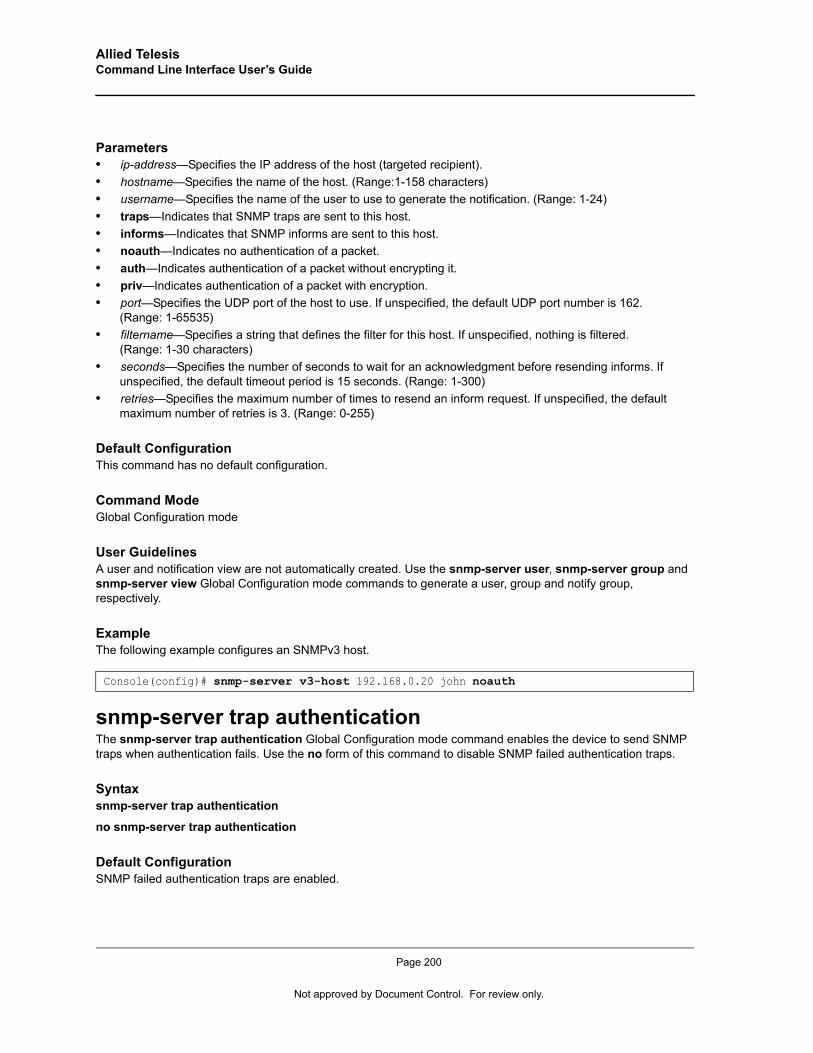
Allied Telesis Command Line Interface User’s Guide
Parameters• ip-address—Specifies the IP address of the host (targeted recipient). • hostname—Specifies the name of the host. (Range:1-158 characters)• username—Specifies the name of the user to use to generate the notification. (Range: 1-24)• traps—Indicates that SNMP traps are sent to this host.• informs—Indicates that SNMP informs are sent to this host.• noauth—Indicates no authentication of a packet.• auth—Indicates authentication of a packet without encrypting it.• priv—Indicates authentication of a packet with encryption.• port—Specifies the UDP port of the host to use. If unspecified, the default UDP port number is 162.
(Range: 1-65535)• filtername—Specifies a string that defines the filter for this host. If unspecified, nothing is filtered.
(Range: 1-30 characters)• seconds—Specifies the number of seconds to wait for an acknowledgment before resending informs. If
unspecified, the default timeout period is 15 seconds. (Range: 1-300)• retries—Specifies the maximum number of times to resend an inform request. If unspecified, the default
maximum number of retries is 3. (Range: 0-255)
Default ConfigurationThis command has no default configuration.
Command ModeGlobal Configuration mode
User GuidelinesA user and notification view are not automatically created. Use the snmp-server user, snmp-server group and snmp-server view Global Configuration mode commands to generate a user, group and notify group, respectively.
ExampleThe following example configures an SNMPv3 host.
snmp-server trap authenticationThe snmp-server trap authentication Global Configuration mode command enables the device to send SNMP traps when authentication fails. Use the no form of this command to disable SNMP failed authentication traps.
Syntaxsnmp-server trap authentication
no snmp-server trap authentication
Default ConfigurationSNMP failed authentication traps are enabled.
Console(config)# snmp-server v3-host 192.168.0.20 john noauth
Page 200
Not approved by Document Control. For review only.
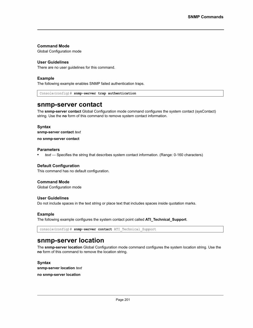
SNMP Commands
Command ModeGlobal Configuration mode
User GuidelinesThere are no user guidelines for this command.
ExampleThe following example enables SNMP failed authentication traps.
snmp-server contactThe snmp-server contact Global Configuration mode command configures the system contact (sysContact) string. Use the no form of this command to remove system contact information.
Syntaxsnmp-server contact text
no snmp-server contact
Parameters• text — Specifies the string that describes system contact information. (Range: 0-160 characters)
Default ConfigurationThis command has no default configuration.
Command ModeGlobal Configuration mode
User GuidelinesDo not include spaces in the text string or place text that includes spaces inside quotation marks.
ExampleThe following example configures the system contact point called ATI_Technical_Support.
snmp-server locationThe snmp-server location Global Configuration mode command configures the system location string. Use the no form of this command to remove the location string.
Syntaxsnmp-server location text
no snmp-server location
Console(config)# snmp-server trap authentication
console(config)# snmp-server contact ATI_Technical_Support
Page 201
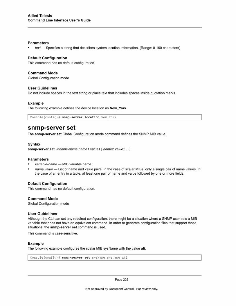
Allied Telesis Command Line Interface User’s Guide
Parameters• text — Specifies a string that describes system location information. (Range: 0-160 characters)
Default ConfigurationThis command has no default configuration.
Command ModeGlobal Configuration mode
User GuidelinesDo not include spaces in the text string or place text that includes spaces inside quotation marks.
ExampleThe following example defines the device location as New_York.
snmp-server setThe snmp-server set Global Configuration mode command defines the SNMP MIB value.
Syntaxsnmp-server set variable-name name1 value1 [ name2 value2 …]
Parameters• variable-name — MIB variable name.• name value — List of name and value pairs. In the case of scalar MIBs, only a single pair of name values. In
the case of an entry in a table, at least one pair of name and value followed by one or more fields.
Default ConfigurationThis command has no default configuration.
Command ModeGlobal Configuration mode
User GuidelinesAlthough the CLI can set any required configuration, there might be a situation where a SNMP user sets a MIB variable that does not have an equivalent command. In order to generate configuration files that support those situations, the snmp-server set command is used.
This command is case-sensitive.
ExampleThe following example configures the scalar MIB sysName with the value ati.
Console(config)# snmp-server location New_York
Console(config)# snmp-server set sysName sysname ati
Page 202
Not approved by Document Control. For review only.
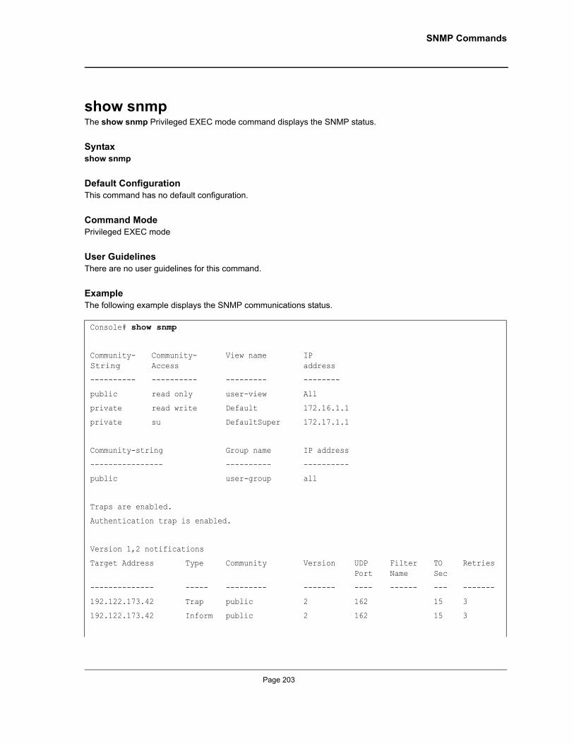
SNMP Commands
show snmpThe show snmp Privileged EXEC mode command displays the SNMP status.
Syntaxshow snmp
Default ConfigurationThis command has no default configuration.
Command ModePrivileged EXEC mode
User GuidelinesThere are no user guidelines for this command.
ExampleThe following example displays the SNMP communications status.
Console# show snmp
Community-String
Community-Access
View name IP address
---------- ---------- --------- --------
public read only user-view All
private read write Default 172.16.1.1
private su DefaultSuper 172.17.1.1
Community-string Group name IP address
---------------- ---------- ----------
public user-group all
Traps are enabled.
Authentication trap is enabled.
Version 1,2 notifications
Target Address Type Community Version UDP Port
Filter Name
TO Sec
Retries
-------------- ----- --------- ------- ---- ------ --- -------
192.122.173.42 Trap public 2 162 15 3
192.122.173.42 Inform public 2 162 15 3
Page 203
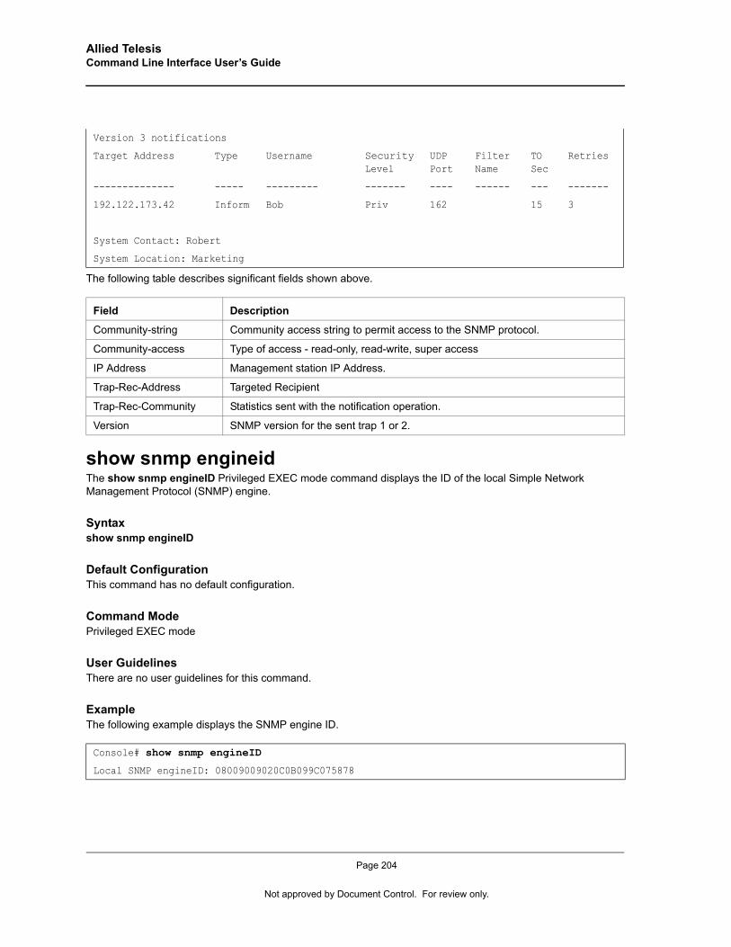
Allied Telesis Command Line Interface User’s Guide
The following table describes significant fields shown above.
show snmp engineidThe show snmp engineID Privileged EXEC mode command displays the ID of the local Simple Network Management Protocol (SNMP) engine.
Syntaxshow snmp engineID
Default ConfigurationThis command has no default configuration.
Command ModePrivileged EXEC mode
User GuidelinesThere are no user guidelines for this command.
ExampleThe following example displays the SNMP engine ID.
Version 3 notifications
Target Address Type Username Security Level
UDP Port
Filter Name
TO Sec
Retries
-------------- ----- --------- ------- ---- ------ --- -------
192.122.173.42 Inform Bob Priv 162 15 3
System Contact: Robert
System Location: Marketing
Field Description
Community-string Community access string to permit access to the SNMP protocol.
Community-access Type of access - read-only, read-write, super access
IP Address Management station IP Address.
Trap-Rec-Address Targeted Recipient
Trap-Rec-Community Statistics sent with the notification operation.
Version SNMP version for the sent trap 1 or 2.
Console# show snmp engineID
Local SNMP engineID: 08009009020C0B099C075878
Page 204
Not approved by Document Control. For review only.
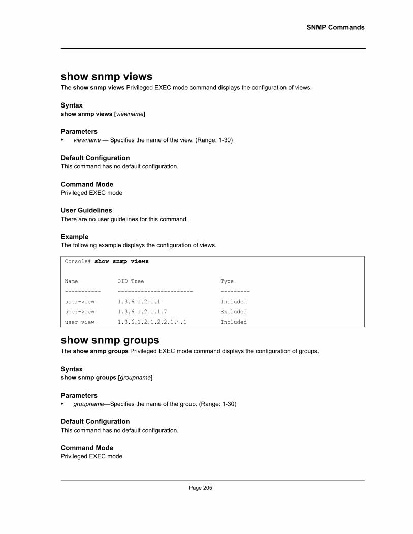
SNMP Commands
show snmp viewsThe show snmp views Privileged EXEC mode command displays the configuration of views.
Syntaxshow snmp views [viewname]
Parameters• viewname — Specifies the name of the view. (Range: 1-30)
Default ConfigurationThis command has no default configuration.
Command ModePrivileged EXEC mode
User GuidelinesThere are no user guidelines for this command.
ExampleThe following example displays the configuration of views.
show snmp groupsThe show snmp groups Privileged EXEC mode command displays the configuration of groups.
Syntaxshow snmp groups [groupname]
Parameters• groupname—Specifies the name of the group. (Range: 1-30)
Default ConfigurationThis command has no default configuration.
Command ModePrivileged EXEC mode
Console# show snmp views
Name OID Tree Type
----------- ----------------------- ---------
user-view 1.3.6.1.2.1.1 Included
user-view 1.3.6.1.2.1.1.7 Excluded
user-view 1.3.6.1.2.1.2.2.1.*.1 Included
Page 205
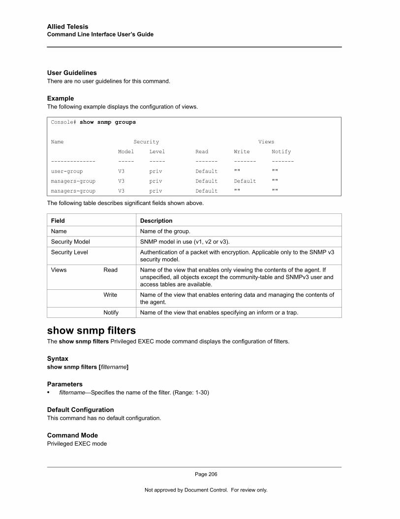
Allied Telesis Command Line Interface User’s Guide
User GuidelinesThere are no user guidelines for this command.
ExampleThe following example displays the configuration of views.
The following table describes significant fields shown above.
show snmp filtersThe show snmp filters Privileged EXEC mode command displays the configuration of filters.
Syntaxshow snmp filters [filtername]
Parameters• filtername—Specifies the name of the filter. (Range: 1-30)
Default ConfigurationThis command has no default configuration.
Command ModePrivileged EXEC mode
Console# show snmp groups
Name Security Views
Model Level Read Write Notify
-------------- ----- ----- ------- ------- -------
user-group V3 priv Default "" ""
managers-group V3 priv Default Default ""
managers-group V3 priv Default "" ""
Field Description
Name Name of the group.
Security Model SNMP model in use (v1, v2 or v3).
Security Level Authentication of a packet with encryption. Applicable only to the SNMP v3 security model.
Views Read Name of the view that enables only viewing the contents of the agent. If unspecified, all objects except the community-table and SNMPv3 user and access tables are available.
Write Name of the view that enables entering data and managing the contents of the agent.
Notify Name of the view that enables specifying an inform or a trap.
Page 206
Not approved by Document Control. For review only.
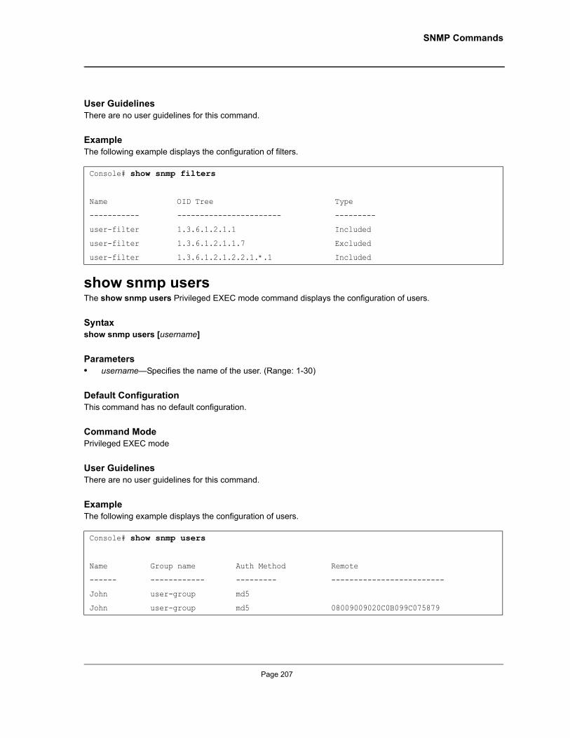
SNMP Commands
User GuidelinesThere are no user guidelines for this command.
ExampleThe following example displays the configuration of filters.
show snmp usersThe show snmp users Privileged EXEC mode command displays the configuration of users.
Syntaxshow snmp users [username]
Parameters• username—Specifies the name of the user. (Range: 1-30)
Default ConfigurationThis command has no default configuration.
Command ModePrivileged EXEC mode
User GuidelinesThere are no user guidelines for this command.
ExampleThe following example displays the configuration of users.
Console# show snmp filters
Name OID Tree Type
----------- ----------------------- ---------
user-filter 1.3.6.1.2.1.1 Included
user-filter 1.3.6.1.2.1.1.7 Excluded
user-filter 1.3.6.1.2.1.2.2.1.*.1 Included
Console# show snmp users
Name Group name Auth Method Remote
------ ------------ --------- -------------------------
John user-group md5
John user-group md5 08009009020C0B099C075879
Page 207
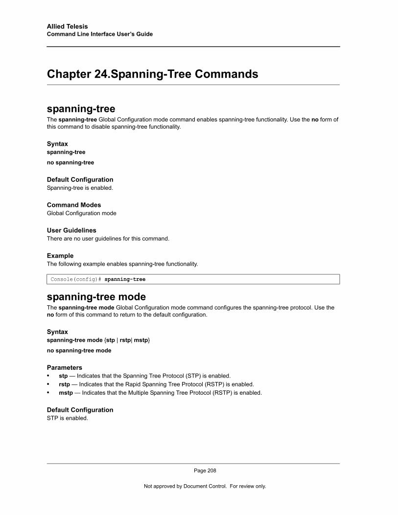
Allied Telesis Command Line Interface User’s Guide
Chapter 24.Spanning-Tree Commands
spanning-treeThe spanning-tree Global Configuration mode command enables spanning-tree functionality. Use the no form of this command to disable spanning-tree functionality.
Syntaxspanning-tree
no spanning-tree
Default ConfigurationSpanning-tree is enabled.
Command Modes Global Configuration mode
User GuidelinesThere are no user guidelines for this command.
ExampleThe following example enables spanning-tree functionality.
spanning-tree modeThe spanning-tree mode Global Configuration mode command configures the spanning-tree protocol. Use the no form of this command to return to the default configuration.
Syntaxspanning-tree mode {stp | rstp| mstp}
no spanning-tree mode
Parameters• stp — Indicates that the Spanning Tree Protocol (STP) is enabled.• rstp — Indicates that the Rapid Spanning Tree Protocol (RSTP) is enabled.• mstp — Indicates that the Multiple Spanning Tree Protocol (RSTP) is enabled.
Default ConfigurationSTP is enabled.
Console(config)# spanning-tree
Page 208
Not approved by Document Control. For review only.
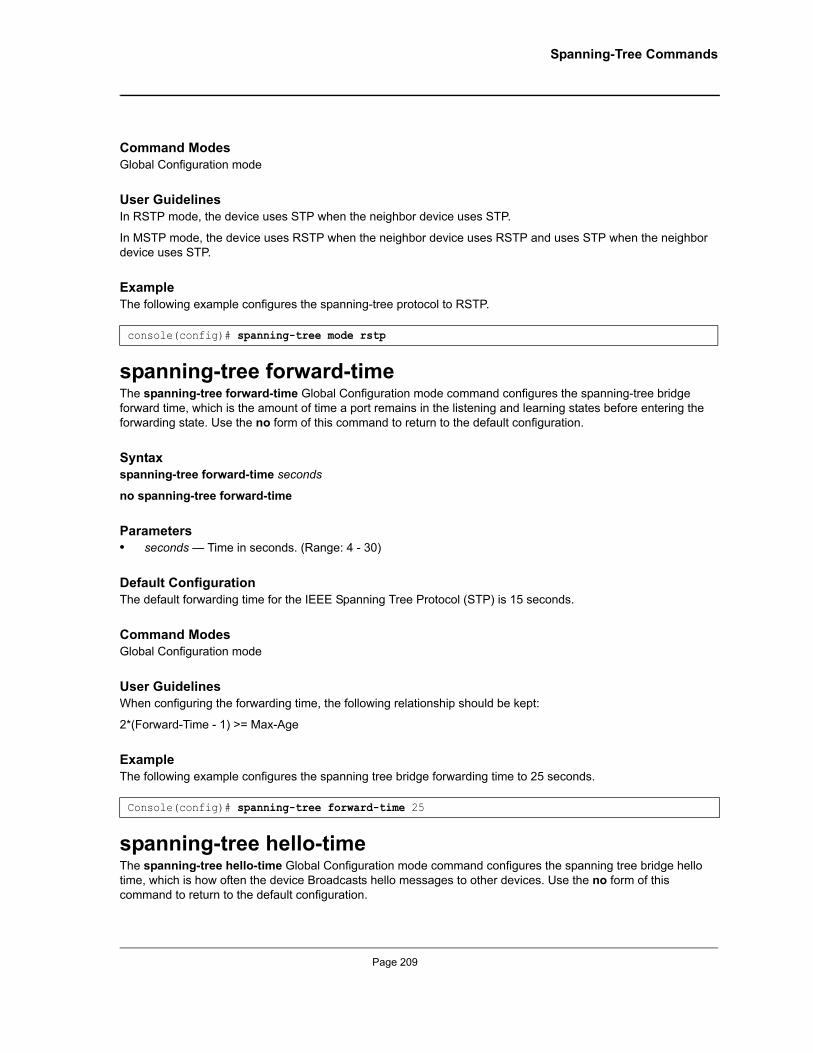
Spanning-Tree Commands
Command Modes Global Configuration mode
User GuidelinesIn RSTP mode, the device uses STP when the neighbor device uses STP.
In MSTP mode, the device uses RSTP when the neighbor device uses RSTP and uses STP when the neighbor device uses STP.
ExampleThe following example configures the spanning-tree protocol to RSTP.
spanning-tree forward-timeThe spanning-tree forward-time Global Configuration mode command configures the spanning-tree bridge forward time, which is the amount of time a port remains in the listening and learning states before entering the forwarding state. Use the no form of this command to return to the default configuration.
Syntaxspanning-tree forward-time seconds
no spanning-tree forward-time
Parameters• seconds — Time in seconds. (Range: 4 - 30)
Default ConfigurationThe default forwarding time for the IEEE Spanning Tree Protocol (STP) is 15 seconds.
Command Modes Global Configuration mode
User GuidelinesWhen configuring the forwarding time, the following relationship should be kept:
2*(Forward-Time - 1) >= Max-Age
ExampleThe following example configures the spanning tree bridge forwarding time to 25 seconds.
spanning-tree hello-timeThe spanning-tree hello-time Global Configuration mode command configures the spanning tree bridge hello time, which is how often the device Broadcasts hello messages to other devices. Use the no form of this command to return to the default configuration.
console(config)# spanning-tree mode rstp
Console(config)# spanning-tree forward-time 25
Page 209
Allied Telesis Command Line Interface User’s Guide
Syntaxspanning-tree hello-time seconds
no spanning-tree hello-time
Parameters• seconds — Time in seconds. (Range: 1 - 10)
Default ConfigurationThe default hello time for IEEE Spanning Tree Protocol (STP) is 2 seconds.
Command Modes Global Configuration mode
User GuidelinesWhen configuring the hello time, the following relationship should be kept:
Max-Age >= 2*(Hello-Time + 1)
ExampleThe following example configures spanning tree bridge hello time to 5 seconds.
spanning-tree max-ageThe spanning-tree max-age Global Configuration mode command configures the spanning tree bridge maximum age. Use the no form of this command to return to the default configuration.
Syntaxspanning-tree max-age seconds
no spanning-tree max-age
Parameters• seconds — Time in seconds. (Range: 6 - 40)
Default ConfigurationThe default maximum age for IEEE Spanning Tree Protocol (STP) is 20 seconds.
Command Modes Global Configuration mode
User GuidelinesWhen configuring the maximum age, the following relationships should be kept:
2*(Forward-Time - 1) >= Max-Age
Max-Age >= 2*(Hello-Time + 1)
Console(config)# spanning-tree hello-time 5
Page 210
Not approved by Document Control. For review only.
Spanning-Tree Commands
ExampleThe following example configures the spanning tree bridge maximum-age to 10 seconds.
spanning-tree priorityThe spanning-tree priority Global Configuration mode command configures the spanning tree priority of the device. The priority value is used to determine which bridge is elected as the root bridge. Use the no form of this command to return to the default configuration.
Syntaxspanning-tree priority priority
no spanning-tree priority
Parameters• priority — Priority of the bridge. (Range: 0 - 61440 in steps of 4096)
Default ConfigurationThe default bridge priority for IEEE Spanning Tree Protocol (STP) is 32768.
Command Modes Global Configuration mode
User GuidelinesThe bridge with the lowest priority is elected as the root bridge.
ExampleThe following example configures spanning tree priority to 12288.
spanning-tree disableThe spanning-tree disable Interface Configuration mode command disables spanning tree on a specific port. Use the no form of this command to enable spanning tree on a port.
Syntaxspanning-tree disable
no spanning-tree disable
Default ConfigurationSpanning tree is enabled on all ports.
Command Modes Interface Configuration (Ethernet, port-channel) mode
Console(config)# spanning-tree max-age 10
Console(config)# spanning-tree priority 12288
Page 211
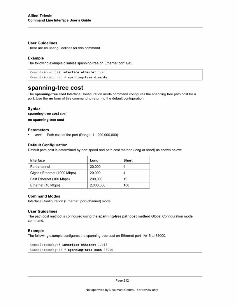
Allied Telesis Command Line Interface User’s Guide
User GuidelinesThere are no user guidelines for this command.
ExampleThe following example disables spanning-tree on Ethernet port 1/e5.
spanning-tree costThe spanning-tree cost Interface Configuration mode command configures the spanning tree path cost for a port. Use the no form of this command to return to the default configuration.
Syntaxspanning-tree cost cost
no spanning-tree cost
Parameters• cost — Path cost of the port (Range: 1 - 200,000,000)
Default ConfigurationDefault path cost is determined by port speed and path cost method (long or short) as shown below:
Command Modes Interface Configuration (Ethernet, port-channel) mode
User GuidelinesThe path cost method is configured using the spanning-tree pathcost method Global Configuration mode command.
ExampleThe following example configures the spanning-tree cost on Ethernet port 1/e15 to 35000.
Console(config)# interface ethernet 1/e5Console(config-if)# spanning-tree disable
Interface Long Short
Port-channel 20,000 4
Gigabit Ethernet (1000 Mbps) 20,000 4
Fast Ethernet (100 Mbps) 200,000 19
Ethernet (10 Mbps) 2,000,000 100
Console(config)# interface ethernet 1/e15Console(config-if)# spanning-tree cost 35000
Page 212
Not approved by Document Control. For review only.
Spanning-Tree Commands
spanning-tree port-priorityThe spanning-tree port-priority Interface Configuration mode command configures port priority. Use the no form of this command to return to the default configuration.
Syntaxspanning-tree port-priority priority
no spanning-tree port-priority
Parameters• priority — The priority of the port. (Range: 0 - 240 in multiples of 16)
Default ConfigurationThe default port priority for IEEE Spanning TreeProtocol (STP) is 128.
Command Modes Interface Configuration (Ethernet, port-channel) mode
User GuidelinesThere are no user guidelines for this command.
ExampleThe following example configures the spanning priority on Ethernet port 1/e15 to 96.
spanning-tree portfastThe spanning-tree portfast Interface Configuration mode command enables PortFast mode. In PortFast mode, the interface is immediately put into the forwarding state upon linkup without waiting for the standard forward time delay. Use the no form of this command to disable PortFast mode.
Syntaxspanning-tree portfast
no spanning-tree portfast
Default ConfigurationPortFast mode is disabled.
Command Modes Interface Configuration (Ethernet, port-channel) mode
User GuidelinesThis feature should be used only with interfaces connected to end stations. Otherwise, an accidental topology loop could cause a data packet loop and disrupt device and network operations.
Console(config)# interface ethernet 1/e15Console(config-if)# spanning-tree port-priority 96
Page 213
Allied Telesis Command Line Interface User’s Guide
ExampleThe following example enables PortFast on Ethernet port 1/e15.
spanning-tree link-typeThe spanning-tree link-type Interface Configuration mode command overrides the default link-type setting determined by the duplex mode of the port and enables Rapid Spanning Tree Protocol (RSTP) transitions to the forwarding state. Use the no form of this command to return to the default configuration.
Syntaxspanning-tree link-type {point-to-point | shared}
no spanning-tree spanning-tree link-type
Parameters• point-to-point —Indicates that the port link type is point-to-point.• shared — Indicates that the port link type is shared.
Default ConfigurationThe device derives the port link type from the duplex mode. A full-duplex port is considered a point-to-point link and a half-duplex port is considered a shared link.
Command Modes Interface Configuration (Ethernet, port-channel) mode
User GuidelinesThere are no user guidelines for this command.
ExampleThe following example enables shared spanning-tree on Ethernet port 1/e5.
spanning-tree pathcost methodThe spanning-tree pathcost method Global Configuration mode command sets the default path cost method. Use the no form of this command to return to the default configuration.
Syntaxspanning-tree pathcost method {long | short}
no spanning-tree pathcost method
Console(config)# interface ethernet 1/e15Console(config-if)# spanning-tree portfast
Console(config)# interface ethernet 1/e15Console(config-if)# spanning-tree link-type shared
Page 214
Not approved by Document Control. For review only.
Spanning-Tree Commands
Parameters• long — Specifies port path costs with a range of 1-200,000,000 .• short — Specifies port path costs with a range of 0-65,535.
Default ConfigurationShort path cost method.
Command Mode Global Configuration mode
User GuidelinesThis command applies to all spanning tree instances on the device.
The cost is set using the spanning-tree cost command.
ExampleThe following example sets the default path cost method to long.
spanning-tree bpduThe spanning-tree bpdu Global Configuration mode command defines BPDU handling when the spanning tree is disabled globally or on a single interface. Use the no form of this command to return to the default configuration.
Syntaxspanning-tree bpdu {filtering | flooding}
Parameters• filtering — Filter BPDU packets when the spanning tree is disabled on an interface.• flooding — Flood BPDU packets when the spanning tree is disabled on an interface.
Default ConfigurationThe default setting is flooding.
Command Modes Global Configuration mode
User GuidelinesThere are no user guidelines for this command.
ExampleThe following example defines BPDU packet flooding when the spanning-tree is disabled on an interface.
Console(config)# spanning-tree pathcost method long
Console(config)# spanning-tree bpdu flooding
Page 215
Allied Telesis Command Line Interface User’s Guide
spanning-tree guard rootThe spanning-tree guard root Interface Configuration (Ethernet, port-channel) mode command enables root guard on all spanning tree instances on the interface. Root guard prevents the interface from becoming the root port of the device. Use the no form of this command to disable root guard on the interface.
Syntaxspanning-tree guard root
no spanning-tree guard root
Default ConfigurationRoot guard is disabled.
Command ModeInterface Configuration (Ethernet, port-channel) mode
User GuidelinesRoot guard can be enabled when the device operates in STP, RSTP and MSTP.
When root guard is enabled, the port changes to the alternate state if spanning-tree calculations selects the port as the root port.
ExampleeThe following example prevents Ethernet port 1/e1 from being the root port of the device.
spanning-tree bpduguardThe spanning-tree bpduguard Interface Configuration (Ethernet, port-channel) mode command shutsdown an interface when it receives a bridge protocol data unit (BPDU). Use the no form of this command to restore the default configuration.
Syntaxspanning-tree bpduguard
no spanning-tree bpduguard
Default ConfigurationThe default configuration is set to disabled.
Command ModeInterface Configuration (Ethernet, port-channel) mode
User GuidelinesYou can enable the command when the spanning tree is enabled (useful when the port is in the PortFast mode) or disabled.
Console(config) # interface ethernet 1/e1Console(config-mst) # spanning-tree guard root
Page 216
Not approved by Document Control. For review only.
Spanning-Tree Commands
ExampleThe following example shutsdown an interface when it receives a BPDU.
clear spanning-tree detected-protocolsThe clear spanning-tree detected-protocols Privileged EXEC mode command restarts the protocol migration process (forces renegotiation with neighboring devices) on all interfaces or on a specified interface.
Syntaxclear spanning-tree detected-protocols [ethernet interface | port-channel port-channel-number]
Parameters• interface — A valid Ethernet port.• port-channel-number — A valid port-channel number.
Default ConfigurationThis command has no default configuration.
Command Modes Privileged EXEC mode
User GuidelinesThis feature should be used only when working in RSTP or MSTP mode.
ExampleThe following example restarts the protocol migration process on Ethernet port 1/e11.
spanning-tree mst priorityThe spanning-tree mst priority Global Configuration mode command configures the device priority for the specified spanning-tree instance. Use the no form of this command to return to the default configuration.
Syntaxspanning-tree mst instance-id priority priority
no spanning-tree mst instance-id priority
Parameters• instance -id—ID of the spanning -tree instance (Range: 1- 7 15).• priority—Device priority for the specified spanning-tree instance (Range: 0-61440 in multiples of 4096).
Console(config)# interface ethernet 1/e1
Console(config-if)# spanning-tree bpduguard
Console# clear spanning-tree detected-protocols ethernet 1/e11
Page 217
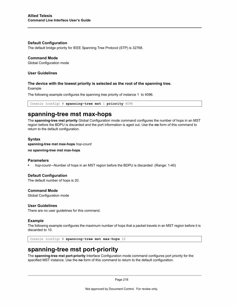
Allied Telesis Command Line Interface User’s Guide
Default ConfigurationThe default bridge priority for IEEE Spanning Tree Protocol (STP) is 32768.
Command Mode Global Configuration mode
User Guidelines
The device with the lowest priority is selected as the root of the spanning tree.Example
The following example configures the spanning tree priority of instance 1 to 4096.
spanning-tree mst max-hopsThe spanning-tree mst priority Global Configuration mode command configures the number of hops in an MST region before the BDPU is discarded and the port information is aged out. Use the no form of this command to return to the default configuration.
Syntaxspanning-tree mst max-hops hop-count
no spanning-tree mst max-hops
Parameters• hop-count—Number of hops in an MST region before the BDPU is discarded .(Range: 1-40)
Default ConfigurationThe default number of hops is 20.
Command Mode Global Configuration mode
User GuidelinesThere are no user guidelines for this command.
ExampleThe following example configures the maximum number of hops that a packet travels in an MST region before it is discarded to 10.
spanning-tree mst port-priorityThe spanning-tree mst port-priority Interface Configuration mode command configures port priority for the specified MST instance. Use the no form of this command to return to the default configuration.
Console (config) # spanning-tree mst 1 priority 4096
Console (config) # spanning-tree mst max-hops 10
Page 218
Not approved by Document Control. For review only.
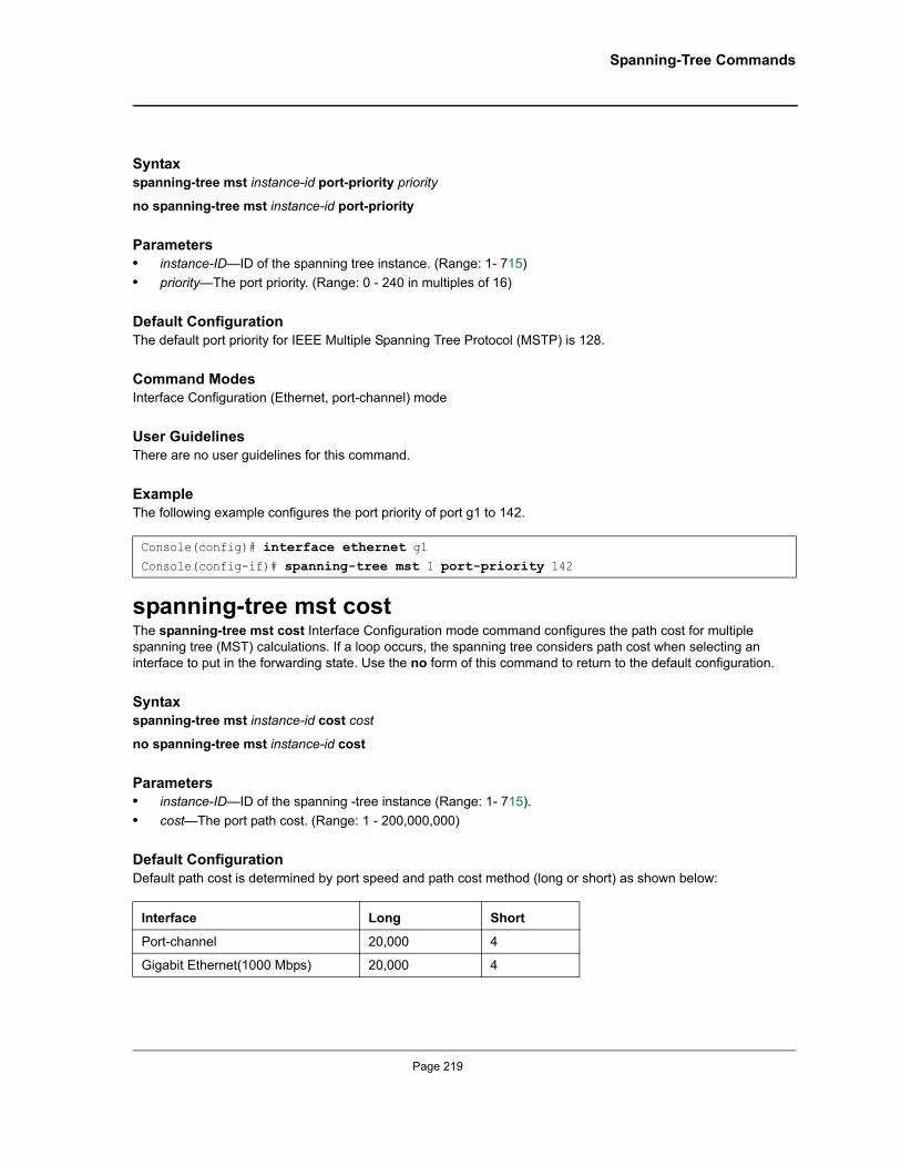
Spanning-Tree Commands
Syntaxspanning-tree mst instance-id port-priority priority
no spanning-tree mst instance-id port-priority
Parameters• instance-ID—ID of the spanning tree instance. (Range: 1- 715)• priority—The port priority. (Range: 0 - 240 in multiples of 16)
Default ConfigurationThe default port priority for IEEE Multiple Spanning Tree Protocol (MSTP) is 128.
Command Modes Interface Configuration (Ethernet, port-channel) mode
User GuidelinesThere are no user guidelines for this command.
ExampleThe following example configures the port priority of port g1 to 142.
spanning-tree mst costThe spanning-tree mst cost Interface Configuration mode command configures the path cost for multiple spanning tree (MST) calculations. If a loop occurs, the spanning tree considers path cost when selecting an interface to put in the forwarding state. Use the no form of this command to return to the default configuration.
Syntaxspanning-tree mst instance-id cost cost
no spanning-tree mst instance-id cost
Parameters• instance-ID—ID of the spanning -tree instance (Range: 1- 715).• cost—The port path cost. (Range: 1 - 200,000,000)
Default ConfigurationDefault path cost is determined by port speed and path cost method (long or short) as shown below:
Console(config)# interface ethernet g1Console(config-if)# spanning-tree mst 1 port-priority 142
Interface Long Short
Port-channel 20,000 4
Gigabit Ethernet(1000 Mbps) 20,000 4
Page 219
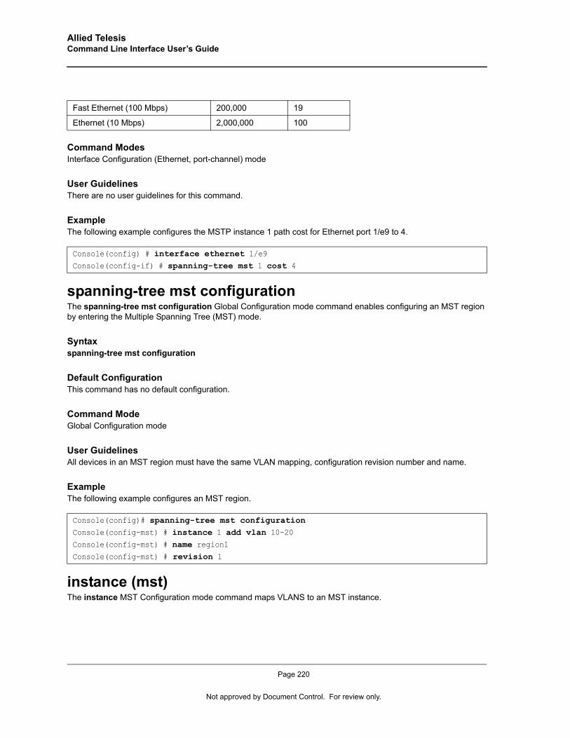
Allied Telesis Command Line Interface User’s Guide
Command Modes Interface Configuration (Ethernet, port-channel) mode
User GuidelinesThere are no user guidelines for this command.
ExampleThe following example configures the MSTP instance 1 path cost for Ethernet port 1/e9 to 4.
spanning-tree mst configurationThe spanning-tree mst configuration Global Configuration mode command enables configuring an MST region by entering the Multiple Spanning Tree (MST) mode.
Syntaxspanning-tree mst configuration
Default ConfigurationThis command has no default configuration.
Command ModeGlobal Configuration mode
User GuidelinesAll devices in an MST region must have the same VLAN mapping, configuration revision number and name.
ExampleThe following example configures an MST region.
instance (mst)The instance MST Configuration mode command maps VLANS to an MST instance.
Fast Ethernet (100 Mbps) 200,000 19
Ethernet (10 Mbps) 2,000,000 100
Console(config) # interface ethernet 1/e9Console(config-if) # spanning-tree mst 1 cost 4
Console(config)# spanning-tree mst configurationConsole(config-mst) # instance 1 add vlan 10-20Console(config-mst) # name region1Console(config-mst) # revision 1
Page 220
Not approved by Document Control. For review only.
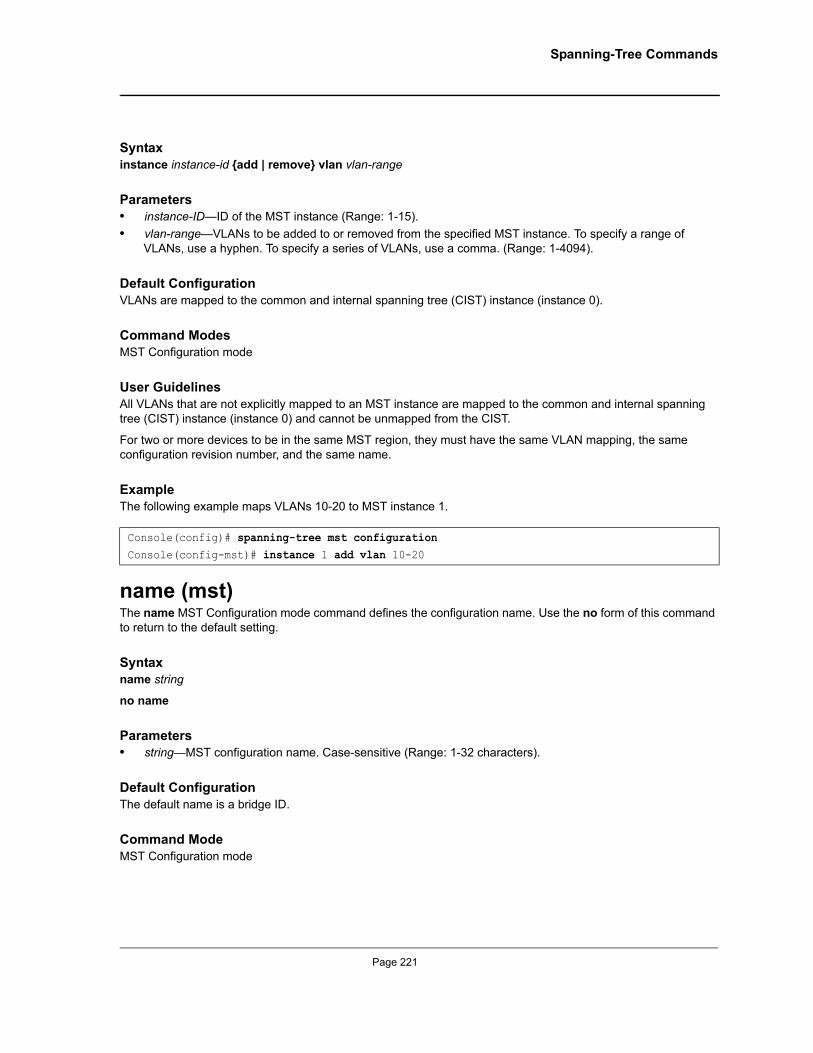
Spanning-Tree Commands
Syntaxinstance instance-id {add | remove} vlan vlan-range
Parameters• instance-ID—ID of the MST instance (Range: 1-15).• vlan-range—VLANs to be added to or removed from the specified MST instance. To specify a range of
VLANs, use a hyphen. To specify a series of VLANs, use a comma. (Range: 1-4094).
Default ConfigurationVLANs are mapped to the common and internal spanning tree (CIST) instance (instance 0).
Command Modes MST Configuration mode
User GuidelinesAll VLANs that are not explicitly mapped to an MST instance are mapped to the common and internal spanning tree (CIST) instance (instance 0) and cannot be unmapped from the CIST.
For two or more devices to be in the same MST region, they must have the same VLAN mapping, the same configuration revision number, and the same name.
ExampleThe following example maps VLANs 10-20 to MST instance 1.
name (mst)The name MST Configuration mode command defines the configuration name. Use the no form of this command to return to the default setting.
Syntaxname string
no name
Parameters• string—MST configuration name. Case-sensitive (Range: 1-32 characters).
Default ConfigurationThe default name is a bridge ID.
Command ModeMST Configuration mode
Console(config)# spanning-tree mst configurationConsole(config-mst)# instance 1 add vlan 10-20
Page 221

Allied Telesis Command Line Interface User’s Guide
User GuidelinesThere are no user guidelines for this command.
ExampleThe following example defines the configuration name as region1.
revision (mst)The revision MST configuration command defines the configuration revision number. Use the no form of this command to return to the default configuration.
Syntaxrevision value
no revision
Parameters• value—Configuration revision number (Range: 0-65535).
Default ConfigurationThe default configuration revision number is 0.
Command ModeMST Configuration mode
User GuidelinesThere are no user guidelines for this command.
ExampleThe following example sets the configuration revision to 1.
show (mst)The show MST Configuration mode command displays the current or pending MST region configuration.
Syntaxshow {current | pending}
Parameters• current—Indicates the current region configuration.• pending—Indicates the pending region configuration.
Console(config) # spanning-tree mst configurationConsole(config-mst) # name region 1
Console(config) # spanning-tree mst configurationConsole(config-mst) # revision 1
Page 222
Not approved by Document Control. For review only.

Spanning-Tree Commands
Default ConfigurationThis command has no default configuration.
Command ModeMST Configuration mode
User GuidelinesThe pending MST region configuration takes effect only after entering the MST configuration mode.
ExampleThe following example displays a pending MST region configuration.
exit (mst)The exit MST Configuration mode command exits the MST configuration mode and applies all configuration changes.
Syntaxexit
Default ConfigurationThis command has no default configuration.
Command ModeMST Configuration mode
User GuidelinesThere are no user guidelines for this command.
ExampleThe following example exits the MST configuration mode and saves changes.
Console(config-mst)# show pending
Pending MST configuration
Name: Region1
Revision: 1
Instance Vlans Mapped State
-------- ------------ -------
0 1-9,21-4094 Enabled
1 10-20 Enabled
Console(config) # spanning-tree mst configurationConsole(config-mst) # exit
Page 223
Allied Telesis Command Line Interface User’s Guide
abort (mst)The abort MST Configuration mode command exits the MST configuration mode without applying the configuration changes.
Syntaxabort
Default ConfigurationThis command has no default configuration.
Command ModeMST Configuration mode
User GuidelinesThere are no user guidelines for this command.
ExampleThe following example exits the MST configuration mode without saving changes.
show spanning-treeThe show spanning-tree Privileged EXEC mode command shows spanning tree configuration.
Syntaxshow spanning-tree [ethernet interface -number| port-channel port-channel-number] [instance instance-id]
show spanning-tree [detail] [active | blockedports] [instance instance-id]
show spanning-tree mst-configuration
Parameters• detail —Display detailed information.• active — Display active ports only.• blockedports — Display blocked ports only.• mst-configuration — Display the MST configuration identifier.• interface-number — Ethernet port number.• port-channel-number — Port channel index.• instance-id — ID associated with a spanning-tree instance.
Default ConfigurationThis command has no default configuration.
Console(config) # spanning-tree mst configurationConsole(config-mst) # abort
Page 224
Not approved by Document Control. For review only.
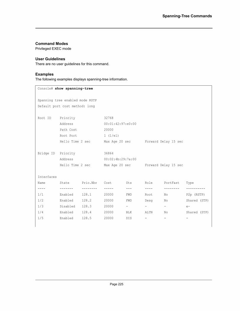
Spanning-Tree Commands
Command Modes Privileged EXEC mode
User GuidelinesThere are no user guidelines for this command.
ExamplesThe following examples displays spanning-tree information.
Console# show spanning-tree
Spanning tree enabled mode RSTP
Default port cost method: long
Root ID Priority 32768
Address 00:01:42:97:e0:00
Path Cost 20000
Root Port 1 (1/e1)
Hello Time 2 sec Max Age 20 sec Forward Delay 15 sec
Bridge ID Priority 36864
Address 00:02:4b:29:7a:00
Hello Time 2 sec Max Age 20 sec Forward Delay 15 sec
Interfaces
Name State Prio.Nbr Cost Sts Role PortFast Type
---- ------- -------- ----- --- ---- -------- ----------
1/1 Enabled 128.1 20000 FWD Root No P2p (RSTP)
1/2 Enabled 128.2 20000 FWD Desg No Shared (STP)
1/3 Disabled 128.3 20000 - - - e-
1/4 Enabled 128.4 20000 BLK ALTN No Shared (STP)
1/5 Enabled 128.5 20000 DIS - - -
Page 225
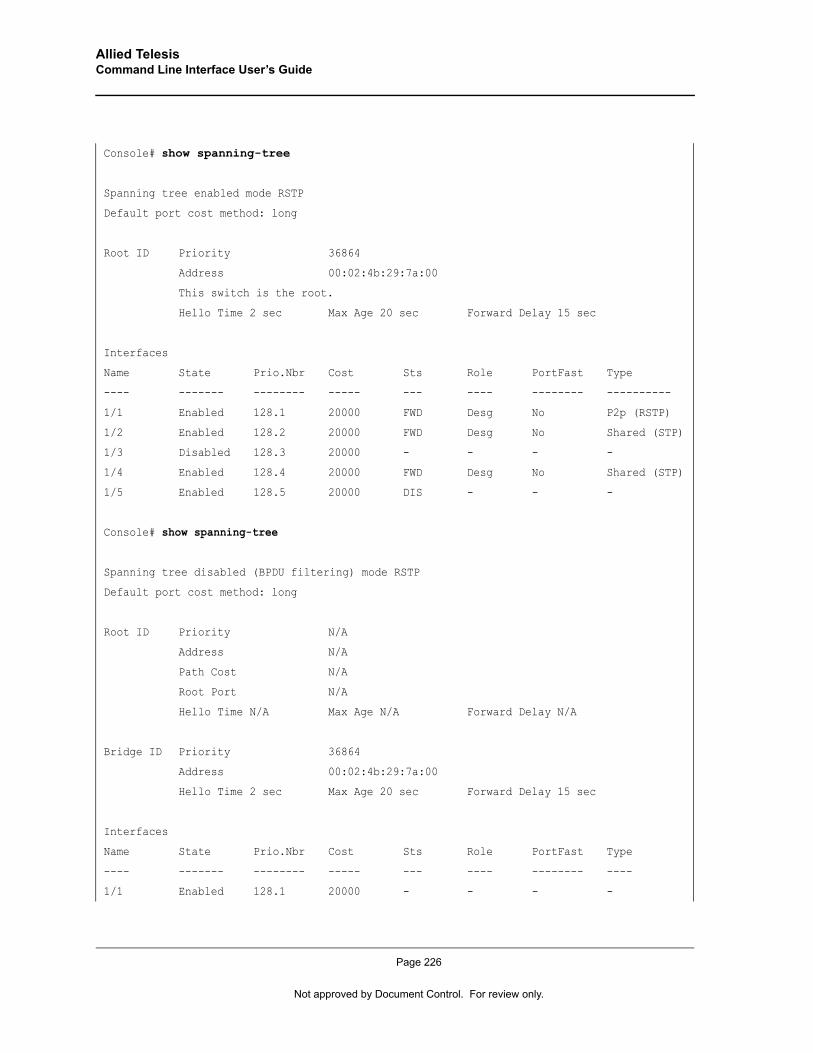
Allied Telesis Command Line Interface User’s Guide
Console# show spanning-tree
Spanning tree enabled mode RSTP
Default port cost method: long
Root ID Priority 36864
Address 00:02:4b:29:7a:00
This switch is the root.
Hello Time 2 sec Max Age 20 sec Forward Delay 15 sec
Interfaces
Name State Prio.Nbr Cost Sts Role PortFast Type
---- ------- -------- ----- --- ---- -------- ----------
1/1 Enabled 128.1 20000 FWD Desg No P2p (RSTP)
1/2 Enabled 128.2 20000 FWD Desg No Shared (STP)
1/3 Disabled 128.3 20000 - - - -
1/4 Enabled 128.4 20000 FWD Desg No Shared (STP)
1/5 Enabled 128.5 20000 DIS - - -
Console# show spanning-tree
Spanning tree disabled (BPDU filtering) mode RSTP
Default port cost method: long
Root ID Priority N/A
Address N/A
Path Cost N/A
Root Port N/A
Hello Time N/A Max Age N/A Forward Delay N/A
Bridge ID Priority 36864
Address 00:02:4b:29:7a:00
Hello Time 2 sec Max Age 20 sec Forward Delay 15 sec
Interfaces
Name State Prio.Nbr Cost Sts Role PortFast Type
---- ------- -------- ----- --- ---- -------- ----
1/1 Enabled 128.1 20000 - - - -
Page 226
Not approved by Document Control. For review only.
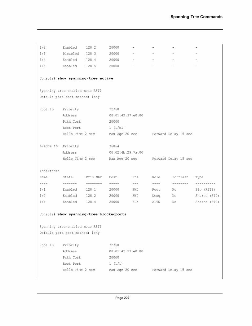
Spanning-Tree Commands
1/2 Enabled 128.2 20000 - - - -
1/3 Disabled 128.3 20000 - - - -
1/4 Enabled 128.4 20000 - - - -
1/5 Enabled 128.5 20000 - - - -
Console# show spanning-tree active
Spanning tree enabled mode RSTP
Default port cost method: long
Root ID Priority 32768
Address 00:01:42:97:e0:00
Path Cost 20000
Root Port 1 (1/e1)
Hello Time 2 sec Max Age 20 sec Forward Delay 15 sec
Bridge ID Priority 36864
Address 00:02:4b:29:7a:00
Hello Time 2 sec Max Age 20 sec Forward Delay 15 sec
Interfaces
Name State Prio.Nbr Cost Sts Role PortFast Type
---- ------- -------- ----- --- ---- -------- ----------
1/1 Enabled 128.1 20000 FWD Root No P2p (RSTP)
1/2 Enabled 128.2 20000 FWD Desg No Shared (STP)
1/4 Enabled 128.4 20000 BLK ALTN No Shared (STP)
Console# show spanning-tree blockedports
Spanning tree enabled mode RSTP
Default port cost method: long
Root ID Priority 32768
Address 00:01:42:97:e0:00
Path Cost 20000
Root Port 1 (1/1)
Hello Time 2 sec Max Age 20 sec Forward Delay 15 sec
Page 227
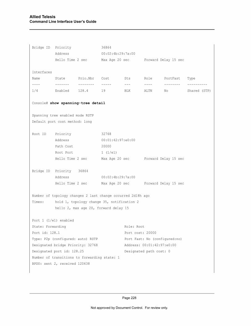
Allied Telesis Command Line Interface User’s Guide
Bridge ID Priority 36864
Address 00:02:4b:29:7a:00
Hello Time 2 sec Max Age 20 sec Forward Delay 15 sec
Interfaces
Name State Prio.Nbr Cost Sts Role PortFast Type
---- ------- -------- ----- --- ---- -------- ----------
1/4 Enabled 128.4 19 BLK ALTN No Shared (STP)
Console# show spanning-tree detail
Spanning tree enabled mode RSTP
Default port cost method: long
Root ID Priority 32768
Address 00:01:42:97:e0:00
Path Cost 20000
Root Port 1 (1/e1)
Hello Time 2 sec Max Age 20 sec Forward Delay 15 sec
Bridge ID Priority 36864
Address 00:02:4b:29:7a:00
Hello Time 2 sec Max Age 20 sec Forward Delay 15 sec
Number of topology changes 2 last change occurred 2d18h ago
Times: hold 1, topology change 35, notification 2
hello 2, max age 20, forward delay 15
Port 1 (1/e1) enabled
State: Forwarding Role: Root
Port id: 128.1 Port cost: 20000
Type: P2p (configured: auto) RSTP Port Fast: No (configured:no)
Designated bridge Priority: 32768 Address: 00:01:42:97:e0:00
Designated port id: 128.25 Designated path cost: 0
Number of transitions to forwarding state: 1
BPDU: sent 2, received 120638
Page 228
Not approved by Document Control. For review only.
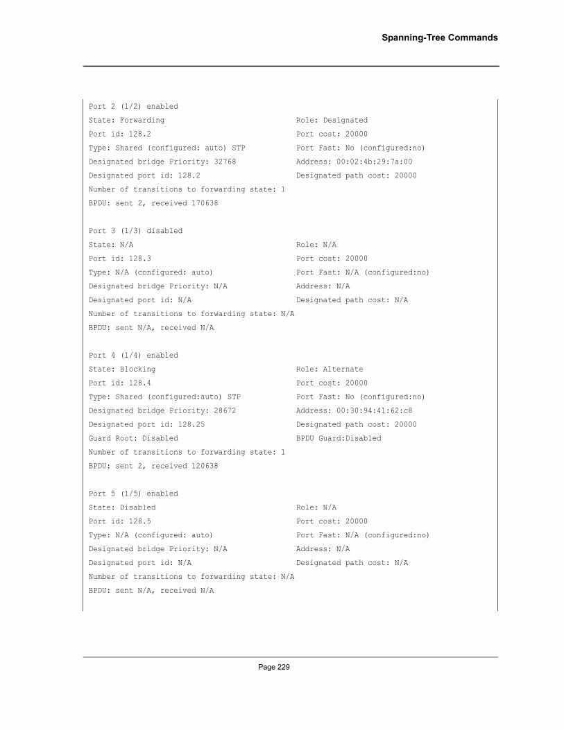
Spanning-Tree Commands
Port 2 (1/2) enabled
State: Forwarding Role: Designated
Port id: 128.2 Port cost: 20000
Type: Shared (configured: auto) STP Port Fast: No (configured:no)
Designated bridge Priority: 32768 Address: 00:02:4b:29:7a:00
Designated port id: 128.2 Designated path cost: 20000
Number of transitions to forwarding state: 1
BPDU: sent 2, received 170638
Port 3 (1/3) disabled
State: N/A Role: N/A
Port id: 128.3 Port cost: 20000
Type: N/A (configured: auto) Port Fast: N/A (configured:no)
Designated bridge Priority: N/A Address: N/A
Designated port id: N/A Designated path cost: N/A
Number of transitions to forwarding state: N/A
BPDU: sent N/A, received N/A
Port 4 (1/4) enabled
State: Blocking Role: Alternate
Port id: 128.4 Port cost: 20000
Type: Shared (configured:auto) STP Port Fast: No (configured:no)
Designated bridge Priority: 28672 Address: 00:30:94:41:62:c8
Designated port id: 128.25 Designated path cost: 20000
Guard Root: Disabled BPDU Guard:Disabled
Number of transitions to forwarding state: 1
BPDU: sent 2, received 120638
Port 5 (1/5) enabled
State: Disabled Role: N/A
Port id: 128.5 Port cost: 20000
Type: N/A (configured: auto) Port Fast: N/A (configured:no)
Designated bridge Priority: N/A Address: N/A
Designated port id: N/A Designated path cost: N/A
Number of transitions to forwarding state: N/A
BPDU: sent N/A, received N/A
Page 229
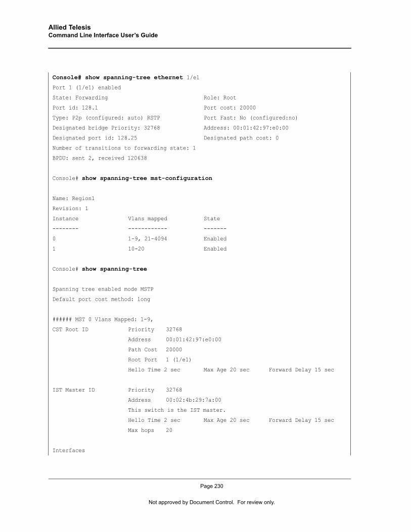
Allied Telesis Command Line Interface User’s Guide
Console# show spanning-tree ethernet 1/e1
Port 1 (1/e1) enabled
State: Forwarding Role: Root
Port id: 128.1 Port cost: 20000
Type: P2p (configured: auto) RSTP Port Fast: No (configured:no)
Designated bridge Priority: 32768 Address: 00:01:42:97:e0:00
Designated port id: 128.25 Designated path cost: 0
Number of transitions to forwarding state: 1
BPDU: sent 2, received 120638
Console# show spanning-tree mst-configuration
Name: Region1
Revision: 1
Instance Vlans mapped State
-------- ------------ -------
0 1-9, 21-4094 Enabled
1 10-20 Enabled
Console# show spanning-tree
Spanning tree enabled mode MSTP
Default port cost method: long
###### MST 0 Vlans Mapped: 1-9,
CST Root ID Priority 32768
Address 00:01:42:97:e0:00
Path Cost 20000
Root Port 1 (1/e1)
Hello Time 2 sec Max Age 20 sec Forward Delay 15 sec
IST Master ID Priority 32768
Address 00:02:4b:29:7a:00
This switch is the IST master.
Hello Time 2 sec Max Age 20 sec Forward Delay 15 sec
Max hops 20
Interfaces
Page 230
Not approved by Document Control. For review only.
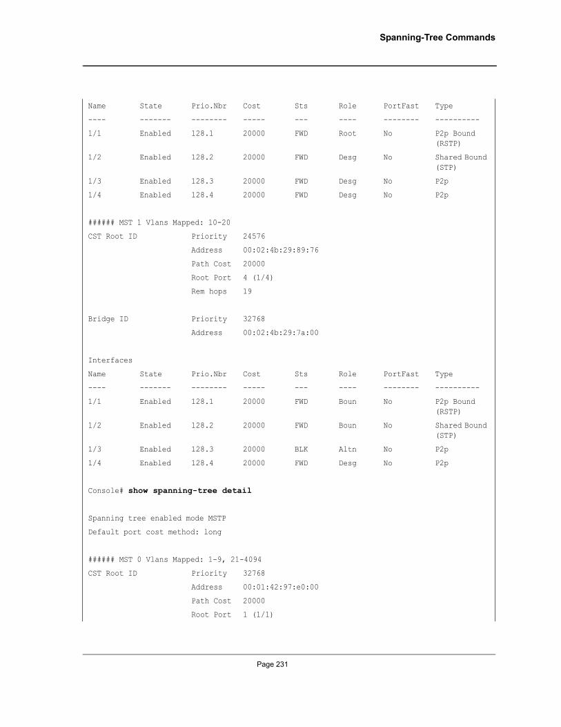
Spanning-Tree Commands
Name State Prio.Nbr Cost Sts Role PortFast Type
---- ------- -------- ----- --- ---- -------- ----------
1/1 Enabled 128.1 20000 FWD Root No P2p Bound (RSTP)
1/2 Enabled 128.2 20000 FWD Desg No Shared Bound (STP)
1/3 Enabled 128.3 20000 FWD Desg No P2p
1/4 Enabled 128.4 20000 FWD Desg No P2p
###### MST 1 Vlans Mapped: 10-20
CST Root ID Priority 24576
Address 00:02:4b:29:89:76
Path Cost 20000
Root Port 4 (1/4)
Rem hops 19
Bridge ID Priority 32768
Address 00:02:4b:29:7a:00
Interfaces
Name State Prio.Nbr Cost Sts Role PortFast Type
---- ------- -------- ----- --- ---- -------- ----------
1/1 Enabled 128.1 20000 FWD Boun No P2p Bound (RSTP)
1/2 Enabled 128.2 20000 FWD Boun No Shared Bound (STP)
1/3 Enabled 128.3 20000 BLK Altn No P2p
1/4 Enabled 128.4 20000 FWD Desg No P2p
Console# show spanning-tree detail
Spanning tree enabled mode MSTP
Default port cost method: long
###### MST 0 Vlans Mapped: 1-9, 21-4094
CST Root ID Priority 32768
Address 00:01:42:97:e0:00
Path Cost 20000
Root Port 1 (1/1)
Page 231

Allied Telesis Command Line Interface User’s Guide
Hello Time 2 sec Max Age 20 sec Forward Delay 15 sec
IST Master ID Priority 32768
Address 00:02:4b:29:7a:00
This switch is the IST master.
Hello Time 2 sec Max Age 20 sec Forward Delay 15 sec
Max hops 20
Number of topology changes 2 last change occurred 2d18h ago
Times: hold 1, topology change 35, notification 2
hello 2, max age 20, forward delay 15
Port 1 (1/e1) enabled
State: Forwarding Role: Root
Port id: 128.1 Port cost: 20000
Type: P2p (configured: auto) Boundary RSTP Port Fast: No (configured:no)
Designated bridge Priority: 32768 Address: 00:01:42:97:e0:00
Designated port id: 128.25 Designated path cost: 0
Number of transitions to forwarding state: 1
BPDU: sent 2, received 120638
Port 2 (1/e2) enabled
State: Forwarding Role: Designated
Port id: 128.2 Port cost: 20000
Type: Shared (configured: auto) Boundary STP Port Fast: No (configured:no)
Designated bridge Priority: 32768 Address: 00:02:4b:29:7a:00
Designated port id: 128.2 Designated path cost: 20000
Number of transitions to forwarding state: 1
BPDU: sent 2, received 170638
Port 3 (1/3) enabled
State: Forwarding Role: Designated
Port id: 128.3 Port cost: 20000
Type: Shared (configured: auto) Internal Port Fast: No (configured:no)
Designated bridge Priority: 32768 Address: 00:02:4b:29:7a:00
Designated port id: 128.3 Designated path cost: 20000
Number of transitions to forwarding state: 1
BPDU: sent 2, received 170638
Page 232
Not approved by Document Control. For review only.
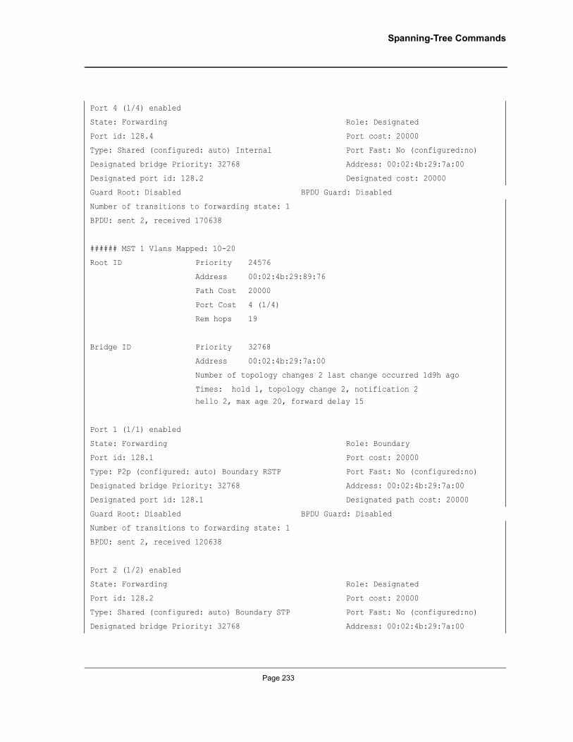
Spanning-Tree Commands
Port 4 (1/4) enabled
State: Forwarding Role: Designated
Port id: 128.4 Port cost: 20000
Type: Shared (configured: auto) Internal Port Fast: No (configured:no)
Designated bridge Priority: 32768 Address: 00:02:4b:29:7a:00
Designated port id: 128.2 Designated cost: 20000
Guard Root: Disabled BPDU Guard: Disabled
Number of transitions to forwarding state: 1
BPDU: sent 2, received 170638
###### MST 1 Vlans Mapped: 10-20
Root ID Priority 24576
Address 00:02:4b:29:89:76
Path Cost 20000
Port Cost 4 (1/4)
Rem hops 19
Bridge ID Priority 32768
Address 00:02:4b:29:7a:00
Number of topology changes 2 last change occurred 1d9h ago
Times: hold 1, topology change 2, notification 2
hello 2, max age 20, forward delay 15
Port 1 (1/1) enabled
State: Forwarding Role: Boundary
Port id: 128.1 Port cost: 20000
Type: P2p (configured: auto) Boundary RSTP Port Fast: No (configured:no)
Designated bridge Priority: 32768 Address: 00:02:4b:29:7a:00
Designated port id: 128.1 Designated path cost: 20000
Guard Root: Disabled BPDU Guard: Disabled
Number of transitions to forwarding state: 1
BPDU: sent 2, received 120638
Port 2 (1/2) enabled
State: Forwarding Role: Designated
Port id: 128.2 Port cost: 20000
Type: Shared (configured: auto) Boundary STP Port Fast: No (configured:no)
Designated bridge Priority: 32768 Address: 00:02:4b:29:7a:00
Page 233
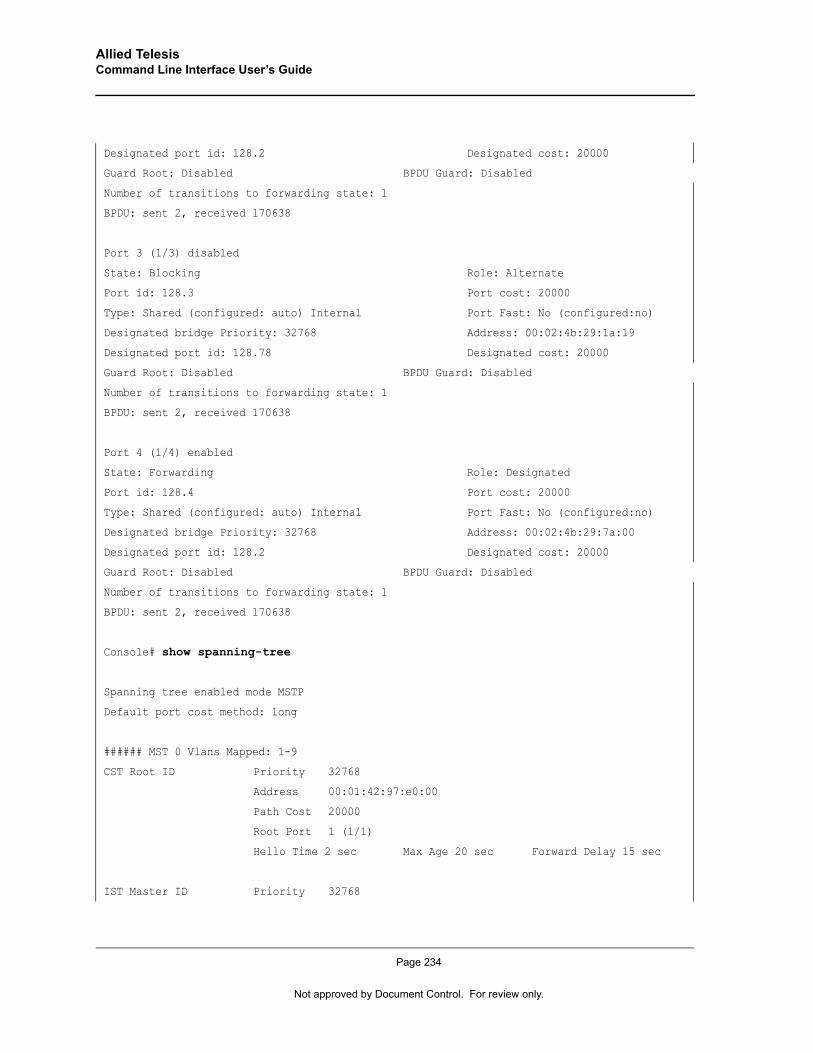
Allied Telesis Command Line Interface User’s Guide
Designated port id: 128.2 Designated cost: 20000
Guard Root: Disabled BPDU Guard: Disabled
Number of transitions to forwarding state: 1
BPDU: sent 2, received 170638
Port 3 (1/3) disabled
State: Blocking Role: Alternate
Port id: 128.3 Port cost: 20000
Type: Shared (configured: auto) Internal Port Fast: No (configured:no)
Designated bridge Priority: 32768 Address: 00:02:4b:29:1a:19
Designated port id: 128.78 Designated cost: 20000
Guard Root: Disabled BPDU Guard: Disabled
Number of transitions to forwarding state: 1
BPDU: sent 2, received 170638
Port 4 (1/4) enabled
State: Forwarding Role: Designated
Port id: 128.4 Port cost: 20000
Type: Shared (configured: auto) Internal Port Fast: No (configured:no)
Designated bridge Priority: 32768 Address: 00:02:4b:29:7a:00
Designated port id: 128.2 Designated cost: 20000
Guard Root: Disabled BPDU Guard: Disabled
Number of transitions to forwarding state: 1
BPDU: sent 2, received 170638
Console# show spanning-tree
Spanning tree enabled mode MSTP
Default port cost method: long
###### MST 0 Vlans Mapped: 1-9
CST Root ID Priority 32768
Address 00:01:42:97:e0:00
Path Cost 20000
Root Port 1 (1/1)
Hello Time 2 sec Max Age 20 sec Forward Delay 15 sec
IST Master ID Priority 32768
Page 234
Not approved by Document Control. For review only.
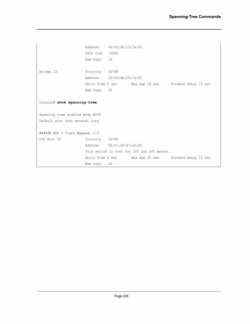
Spanning-Tree Commands
Address 00:02:4b:19:7a:00
Path Cost 10000
Rem hops 19
Bridge ID Priority 32768
Address 00:02:4b:29:7a:00
Hello Time 2 sec Max Age 20 sec Forward Delay 15 sec
Max hops 20
Console# show spanning-tree
Spanning tree enabled mode MSTP
Default port cost method: long
###### MST 0 Vlans Mapped: 1-9
CST Root ID Priority 32768
Address 00:01:42:97:e0:00
This switch is root for CST and IST master.
Hello Time 2 sec Max Age 20 sec Forward Delay 15 sec
Max hops 20
Page 235

Allied Telesis Command Line Interface User’s Guide
Chapter 25.SSH Commands
ip ssh portThe ip ssh port Global Configuration mode command specifies the port to be used by the SSH server. Use the no form of this command to return to the default configuration.
Syntaxip ssh port port-number
no ip ssh port
Parameters• port-number — Port number for use by the SSH server (Range: 1 - 65535).
Default ConfigurationThe default port number is 22.
Command ModeGlobal Configuration mode
User GuidelinesThere are no user guidelines for this command.
ExampleThe following example specifies the port to be used by the SSH server as 8080.
ip ssh serverThe ip ssh server Global Configuration mode command enables the device to be configured from a SSH server. Use the no form of this command to disable this function.
Syntaxip ssh server
no ip ssh server
Default ConfigurationDevice configuration from a SSH server is enabled.
Command ModeGlobal Configuration mode
Console(config)# ip ssh port 8080
Page 236
Not approved by Document Control. For review only.
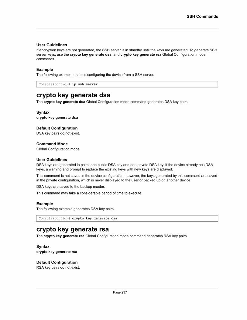
SSH Commands
User GuidelinesIf encryption keys are not generated, the SSH server is in standby until the keys are generated. To generate SSH server keys, use the crypto key generate dsa, and crypto key generate rsa Global Configuration mode commands.
ExampleThe following example enables configuring the device from a SSH server.
crypto key generate dsaThe crypto key generate dsa Global Configuration mode command generates DSA key pairs.
Syntaxcrypto key generate dsa
Default ConfigurationDSA key pairs do not exist.
Command ModeGlobal Configuration mode
User GuidelinesDSA keys are generated in pairs: one public DSA key and one private DSA key. If the device already has DSA keys, a warning and prompt to replace the existing keys with new keys are displayed.
This command is not saved in the device configuration; however, the keys generated by this command are saved in the private configuration, which is never displayed to the user or backed up on another device.
DSA keys are saved to the backup master.
This command may take a considerable period of time to execute.
ExampleThe following example generates DSA key pairs.
crypto key generate rsaThe crypto key generate rsa Global Configuration mode command generates RSA key pairs.
Syntaxcrypto key generate rsa
Default ConfigurationRSA key pairs do not exist.
Console(config)# ip ssh server
Console(config)# crypto key generate dsa
Page 237
Allied Telesis Command Line Interface User’s Guide
Command ModeGlobal Configuration mode
User GuidelinesRSA keys are generated in pairs: one public RSA key and one private RSA key. If the device already has RSA keys, a warning and prompt to replace the existing keys with new keys are displayed.
This command is not saved in the device configuration; however, the keys generated by this command are saved in the private configuration which is never displayed to the user or backed up on another device.
RSA keys are saved to the backup master.
This command may take a considerable period of time to execute.
ExampleThe following example generates RSA key pairs.
ip ssh pubkey-authThe ip ssh pubkey-auth Global Configuration mode command enables public key authentication for incoming SSH sessions. Use the no form of this command to disable this function.
Syntaxip ssh pubkey-auth
no ip ssh pubkey-auth
Default ConfigurationPublic Key authentication for incoming SSH sessions is disabled.
Command ModeGlobal Configuration mode
User GuidelinesAAA authentication is independent
ExampleThe following example enables public key authentication for incoming SSH sessions.
crypto key pubkey-chain sshThe crypto key pubkey-chain ssh Global Configuration mode command enters the SSH Public Key-chain Configuration mode. The mode is used to manually specify other device public keys such as SSH client public keys.
Console(config)# crypto key generate rsa
Console(config)# ip ssh pubkey-auth
Page 238
Not approved by Document Control. For review only.
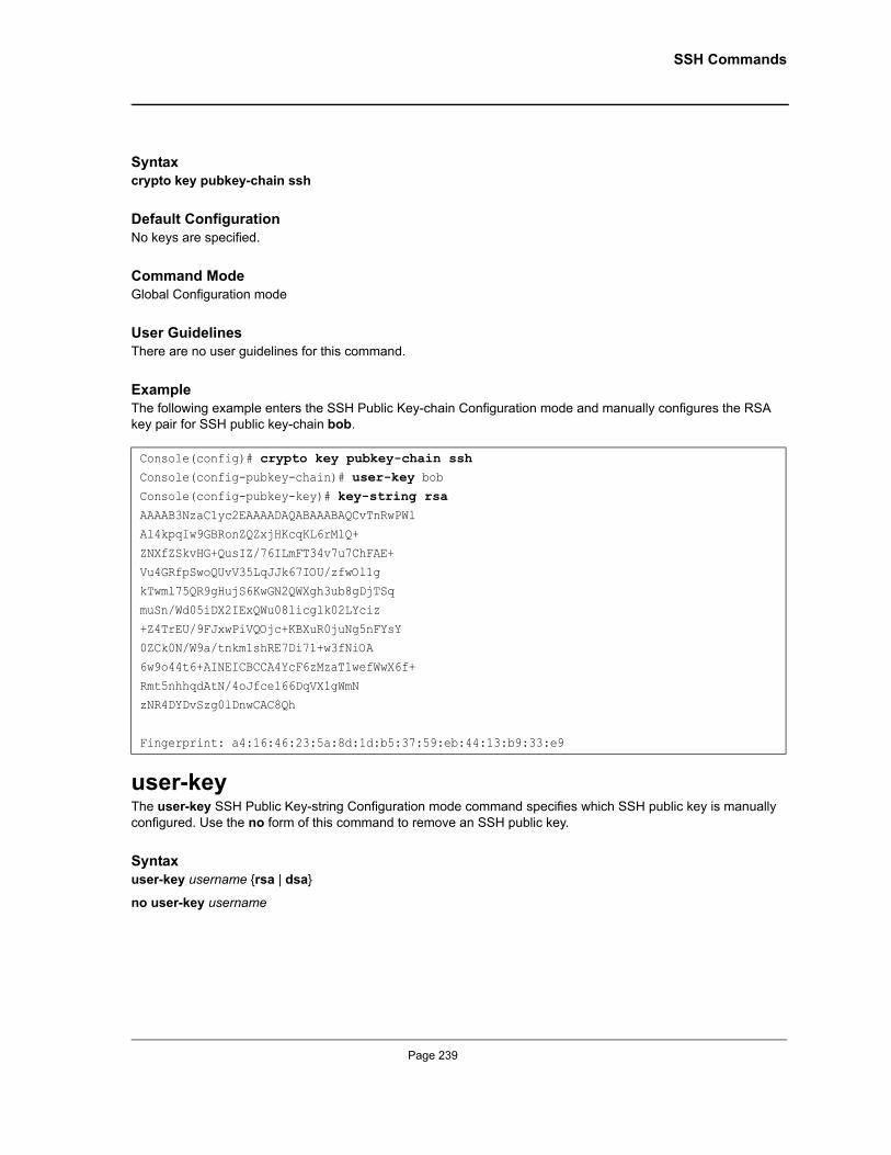
SSH Commands
Syntaxcrypto key pubkey-chain ssh
Default ConfigurationNo keys are specified.
Command ModeGlobal Configuration mode
User GuidelinesThere are no user guidelines for this command.
ExampleThe following example enters the SSH Public Key-chain Configuration mode and manually configures the RSA key pair for SSH public key-chain bob.
user-keyThe user-key SSH Public Key-string Configuration mode command specifies which SSH public key is manually configured. Use the no form of this command to remove an SSH public key.
Syntaxuser-key username {rsa | dsa}
no user-key username
Console(config)# crypto key pubkey-chain sshConsole(config-pubkey-chain)# user-key bob Console(config-pubkey-key)# key-string rsaAAAAB3NzaC1yc2EAAAADAQABAAABAQCvTnRwPWlAl4kpqIw9GBRonZQZxjHKcqKL6rMlQ+
ZNXfZSkvHG+QusIZ/76ILmFT34v7u7ChFAE+
Vu4GRfpSwoQUvV35LqJJk67IOU/zfwOl1gkTwml75QR9gHujS6KwGN2QWXgh3ub8gDjTSq
muSn/Wd05iDX2IExQWu08licglk02LYciz
+Z4TrEU/9FJxwPiVQOjc+KBXuR0juNg5nFYsY0ZCk0N/W9a/tnkm1shRE7Di71+w3fNiOA
6w9o44t6+AINEICBCCA4YcF6zMzaT1wefWwX6f+
Rmt5nhhqdAtN/4oJfce166DqVX1gWmNzNR4DYDvSzg0lDnwCAC8Qh
Fingerprint: a4:16:46:23:5a:8d:1d:b5:37:59:eb:44:13:b9:33:e9
Page 239
Allied Telesis Command Line Interface User’s Guide
Parameters• username — Specifies the username of the remote SSH client. (Range: 1-48 characters)• rsa — Indicates the RSA key pair.• dsa — Indicates the DSA key pair.
Default ConfigurationNo SSH public keys exist.
Command ModeSSH Public Key-string Configuration mode
User GuidelinesFollow this command with the key-string SSH Public Key-String Configuration mode command to specify the key.
ExampleThe following example enables manually configuring an SSH public key for SSH public key-chain bob.
key-stringThe key-string SSH Public Key-string Configuration mode command manually specifies an SSH public key.
Syntaxkey-string
key-string row key-string
Parameters• row — Indicates the SSH public key row by row.• key-string—Specifies the key in UU-encoded DER format; UU-encoded DER format is the same format in the
authorized_keys file used by OpenSSH.
Default ConfigurationNo keys exist.
Command ModeSSH Public Key-string Configuration mode
User GuidelinesUse the key-string SSH Public Key-string Configuration mode command to specify which SSH public key is to be interactively configured next. To complete the command, you must enter a row with no characters.
Console(config)# crypto key pubkey-chain sshConsole(config-pubkey-chain)# user-key bob rsaConsole(config-pubkey-key)# key-string rowAAAAB3NzaC1yc2EAAAADAQABAAABAQCvTnRwPWl
Page 240
Not approved by Document Control. For review only.
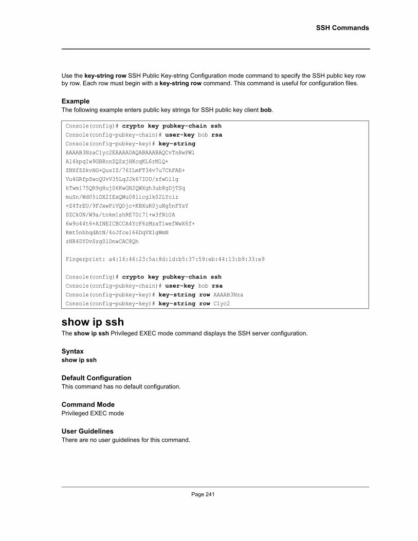
SSH Commands
Use the key-string row SSH Public Key-string Configuration mode command to specify the SSH public key row by row. Each row must begin with a key-string row command. This command is useful for configuration files.
ExampleThe following example enters public key strings for SSH public key client bob.
show ip sshThe show ip ssh Privileged EXEC mode command displays the SSH server configuration.
Syntaxshow ip ssh
Default ConfigurationThis command has no default configuration.
Command ModePrivileged EXEC mode
User GuidelinesThere are no user guidelines for this command.
Console(config)# crypto key pubkey-chain sshConsole(config-pubkey-chain)# user-key bob rsaConsole(config-pubkey-key)# key-stringAAAAB3NzaC1yc2EAAAADAQABAAABAQCvTnRwPWl
Al4kpqIw9GBRonZQZxjHKcqKL6rMlQ+ZNXfZSkvHG+QusIZ/76ILmFT34v7u7ChFAE+
Vu4GRfpSwoQUvV35LqJJk67IOU/zfwOl1g
kTwml75QR9gHujS6KwGN2QWXgh3ub8gDjTSqmuSn/Wd05iDX2IExQWu08licglk02LYciz
+Z4TrEU/9FJxwPiVQOjc+KBXuR0juNg5nFYsY
0ZCk0N/W9a/tnkm1shRE7Di71+w3fNiOA6w9o44t6+AINEICBCCA4YcF6zMzaT1wefWwX6f+
Rmt5nhhqdAtN/4oJfce166DqVX1gWmN
zNR4DYDvSzg0lDnwCAC8Qh
Fingerprint: a4:16:46:23:5a:8d:1d:b5:37:59:eb:44:13:b9:33:e9
Console(config)# crypto key pubkey-chain sshConsole(config-pubkey-chain)# user-key bob rsaConsole(config-pubkey-key)# key-string row AAAAB3NzaConsole(config-pubkey-key)# key-string row C1yc2
Page 241
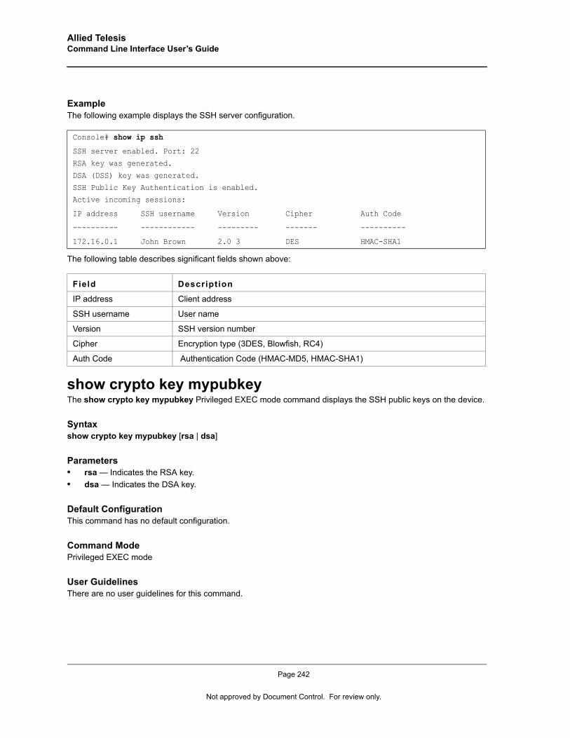
Allied Telesis Command Line Interface User’s Guide
ExampleThe following example displays the SSH server configuration.
The following table describes significant fields shown above:
show crypto key mypubkeyThe show crypto key mypubkey Privileged EXEC mode command displays the SSH public keys on the device.
Syntaxshow crypto key mypubkey [rsa | dsa]
Parameters• rsa — Indicates the RSA key.• dsa — Indicates the DSA key.
Default ConfigurationThis command has no default configuration.
Command ModePrivileged EXEC mode
User GuidelinesThere are no user guidelines for this command.
Console# show ip ssh
SSH server enabled. Port: 22
RSA key was generated.
DSA (DSS) key was generated.SSH Public Key Authentication is enabled.
Active incoming sessions:
IP address SSH username Version Cipher Auth Code
---------- ------------ --------- ------- ----------
172.16.0.1 John Brown 2.0 3 DES HMAC-SHA1
Field Description
IP address Client address
SSH username User name
Version SSH version number
Cipher Encryption type (3DES, Blowfish, RC4)
Auth Code Authentication Code (HMAC-MD5, HMAC-SHA1)
Page 242
Not approved by Document Control. For review only.
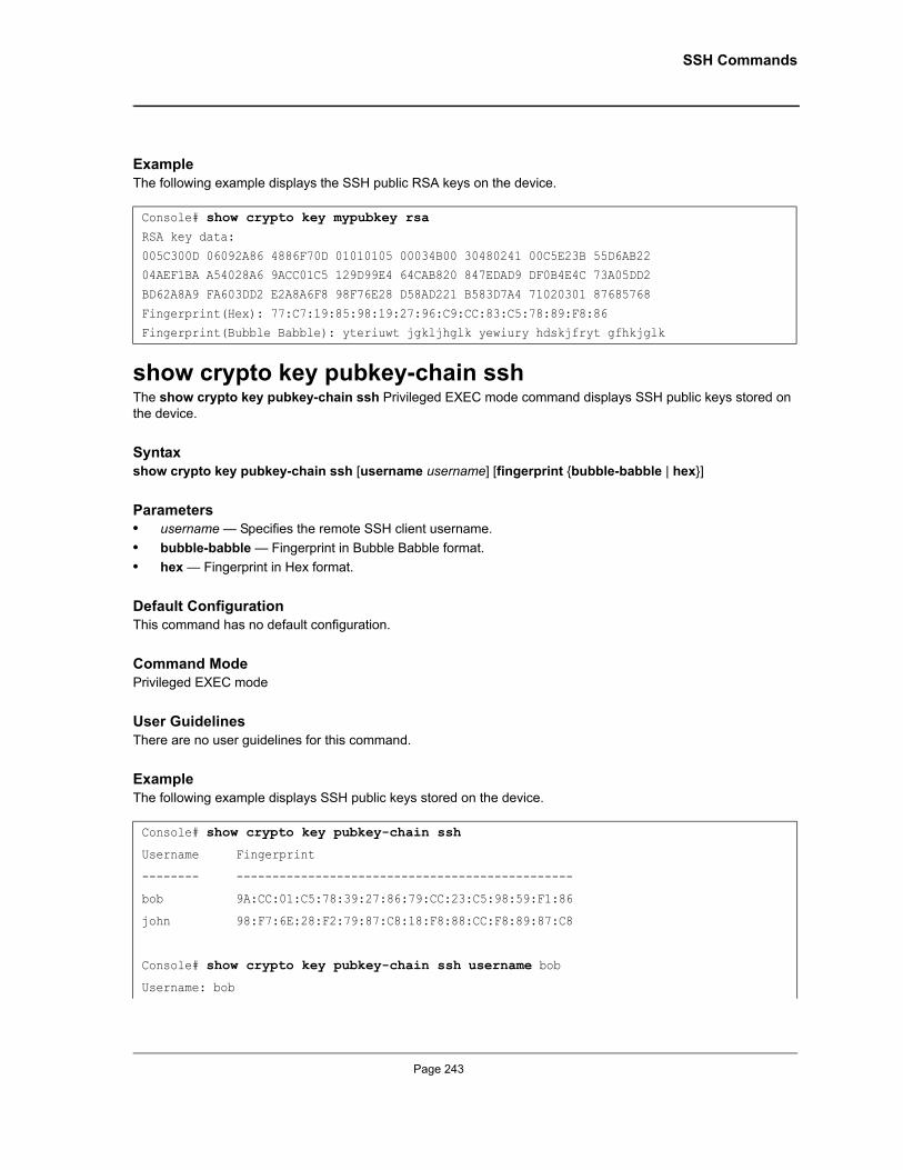
SSH Commands
ExampleThe following example displays the SSH public RSA keys on the device.
show crypto key pubkey-chain sshThe show crypto key pubkey-chain ssh Privileged EXEC mode command displays SSH public keys stored on the device.
Syntaxshow crypto key pubkey-chain ssh [username username] [fingerprint {bubble-babble | hex}]
Parameters• username — Specifies the remote SSH client username.• bubble-babble — Fingerprint in Bubble Babble format.• hex — Fingerprint in Hex format.
Default ConfigurationThis command has no default configuration.
Command ModePrivileged EXEC mode
User GuidelinesThere are no user guidelines for this command.
ExampleThe following example displays SSH public keys stored on the device.
Console# show crypto key mypubkey rsaRSA key data:
005C300D 06092A86 4886F70D 01010105 00034B00 30480241 00C5E23B 55D6AB22 04AEF1BA A54028A6 9ACC01C5 129D99E4 64CAB820 847EDAD9 DF0B4E4C 73A05DD2
BD62A8A9 FA603DD2 E2A8A6F8 98F76E28 D58AD221 B583D7A4 71020301 87685768
Fingerprint(Hex): 77:C7:19:85:98:19:27:96:C9:CC:83:C5:78:89:F8:86Fingerprint(Bubble Babble): yteriuwt jgkljhglk yewiury hdskjfryt gfhkjglk
Console# show crypto key pubkey-chain ssh
Username Fingerprint
-------- -----------------------------------------------
bob 9A:CC:01:C5:78:39:27:86:79:CC:23:C5:98:59:F1:86
john 98:F7:6E:28:F2:79:87:C8:18:F8:88:CC:F8:89:87:C8
Console# show crypto key pubkey-chain ssh username bob
Username: bob
Page 243

Allied Telesis Command Line Interface User’s Guide
Key: 005C300D 06092A86 4886F70D 01010105 00034B00 30480241 00C5E23B 55D6AB22 04AEF1BA A54028A6 9ACC01C5 129D99E4
Fingerprint: 9A:CC:01:C5:78:39:27:86:79:CC:23:C5:98:59:F1:86
Page 244
Not approved by Document Control. For review only.
Syslog Commands
Chapter 26.Syslog Commands
logging onThe logging on Global Configuration mode command controls error message logging. This command sends debug or error messages to a logging process, which logs messages to designated locations asynchronously to the process that generated the messages. Use the no form of this command to disable the logging process.
Syntaxlogging on
no logging on
Default ConfigurationLogging is enabled.
Command ModeGlobal Configuration mode
User GuidelinesThe logging process controls the distribution of logging messages at various destinations, such as the logging buffer, logging file or syslog server. Logging on and off at these destinations can be individually configured using the logging buffered, logging file, and logging Global Configuration mode commands. However, if the logging on command is disabled, no messages are sent to these destinations. Only the console receives messages.
ExampleThe following example enables logging error messages.
loggingThe logging Global Configuration mode command logs messages to a syslog server. Use the no form of this command to delete the syslog server with the specified address from the list of syslogs.
Syntaxlogging {ip-address | hostname} [port port] [severity level] [facility facility] [description text]
no logging {ip-address | hostname}
Console(config)# logging on
Page 245
Allied Telesis Command Line Interface User’s Guide
Parameters• ip-address — IP address of the host to be used as a syslog server. • hostname — Specifies the host name of the syslog server. (Range: 1-158 characters)• port — Specifies the port number for syslog messages. (Range: 1 - 65535)• level — Specifies the severity level of logged messages sent to the syslog servers. Possible values:
emergencies, alerts, critical, errors, warnings, notifications, informational and debugging. • facility — Specifies the facility that is indicated in the message. Possible values: local0, local1, local2,
local3, local4, local5, local 6, local7.• text — Syslog server description. (Range: 1-64 characters)
Default ConfigurationThe default port number is 514.
The default logging message level is informational.
The default facility is local7.
Command ModeGlobal Configuration mode
User GuidelinesUp to 8 syslog servers can be used.
If no specific severity level is specified, the global values apply to each server.
ExampleThe following example limits logged messages sent to the syslog server with IP address 10.1.1.1 to severity level critical.
logging consoleThe logging console Global Configuration mode command limits messages logged to the console based on severity. Use the no form of this command to disable logging to the console.
Syntaxlogging console level
no logging console
Parameters• level — Specifies the severity level of logged messages displayed on the console. Possible values:
emergencies, alerts, critical, errors, warnings, notifications, informational, debugging.
Default ConfigurationThe default severity level is informational.
Console(config)# logging 10.1.1.1 severity critical
Page 246
Not approved by Document Control. For review only.
Syslog Commands
Command ModeGlobal Configuration mode
User GuidelinesThere are no user guidelines for this command.
ExampleThe following example limits logging messages displayed on the console to severity level errors.
logging bufferedThe logging buffered Global Configuration mode command limits syslog messages displayed from an internal buffer based on severity. Use the no form of this command to cancel using the buffer.
Syntaxlogging buffered level
no logging buffered
Parameters• level — Specifies the severity level of messages logged in the buffer. Possible values: emergencies, alerts,
critical, errors, warnings, notifications, informational, debugging.
Default ConfigurationThe default severity level is informational.
Command ModeGlobal Configuration mode
User GuidelinesAll the syslog messages are logged to the internal buffer. This command limits the messages displayed to the user.
ExampleThe following example limits syslog messages displayed from an internal buffer based on severity level debugging.
logging buffered sizeThe logging buffered size Global Configuration mode command changes the number of syslog messages stored in the internal buffer. Use the no form of this command to return to the default configuration.
Console(config)# logging console errors
Console(config)# logging buffered debugging
Page 247
Allied Telesis Command Line Interface User’s Guide
Syntaxlogging buffered size number
no logging buffered size
Parameters• number — Specifies the maximum number of messages stored in the history table. (Range: 20 - 400)
Default ConfigurationThe default number of messages is 200.
Command ModeGlobal Configuration mode
User GuidelinesThis command takes effect only after Reset.
ExampleThe following example changes the number of syslog messages stored in the internal buffer to 300.
clear loggingThe clear logging Privileged EXEC mode command clears messages from the internal logging buffer.
Syntaxclear logging
Default ConfigurationThis command has no default configuration.
Command ModePrivileged EXEC mode
User GuidelinesThere are no user guidelines for this command.
ExampleThe following example clears messages from the internal logging buffer.
Console(config)# logging buffered size 300
Console# clear loggingClear logging buffer [confirm]
Page 248
Not approved by Document Control. For review only.
Syslog Commands
logging fileThe logging file Global Configuration mode command limits syslog messages sent to the logging file based on severity. Use the no form of this command to cancel using the buffer.
Syntaxlogging file level
no logging file
Parameters• level — Specifies the severity level of syslog messages sent to the logging file. Possible values:
emergencies, alerts, critical, errors, warnings, notifications, informational and debugging.
Default ConfigurationThe default severity level is errors.
Command ModeGlobal Configuration mode
User GuidelinesThere are no user guidelines for this command.
ExampleThe following example limits syslog messages sent to the logging file based on severity level alerts.
clear logging fileThe clear logging file Privileged EXEC mode command clears messages from the logging file.
Syntaxclear logging file
Default ConfigurationThis command has no default configuration.
Command ModePrivileged EXEC mode
User GuidelinesThere are no user guidelines for this command.
Console(config)# logging file alerts
Page 249
Allied Telesis Command Line Interface User’s Guide
ExampleThe following example clears messages from the logging file.
aaa loggingThe aaa logging Global Configuration mode command enables logging AAA login events. Use the no form of this command to disable logging AAA login events.
Syntaxaaa logging login
no aaa logging login
Parameters• login — Indicates logging messages related to successful login events, unsuccessful login events and other
login-related events.
Default ConfigurationLogging AAA login events is enabled.
Command ModeGlobal Configuration mode
User GuidelinesOther types of AAA events are not subject to this command.
ExampleThe following example enables logging messages related to AAA login events.
file-system loggingThe file-system logging Global Configuration mode command enables logging file system events. Use the no form of this command to disable logging file system events.
Syntaxfile-system logging copy
no file-system logging copy
file-system logging delete-rename
no file-system logging delete-rename
Console# clear logging fileClear Logging File [confirm]
Console(config)# aaa logging login
Page 250
Not approved by Document Control. For review only.
Syslog Commands
Parameters• copy — Indicates logging messages related to file copy operations.• delete-rename — Indicates logging messages related to file deletion and renaming operations.
Default ConfigurationLogging file system events is enabled.
Command ModeGlobal Configuration mode
User GuidelinesThere are no user guidelines for this command.
ExampleThe following example enables logging messages related to file copy operations.
management loggingThe management logging Global Configuration mode command enables logging management Access List (ACL) events. Use the no form of this command to disable logging management Access List events.
Syntaxmanagement logging deny
no management logging deny
Parameters• deny — Indicates logging messages related to deny actions of management ACLs.
Default ConfigurationLogging management ACL events is enabled.
Command ModeGlobal Configuration mode
User GuidelinesOther types of management ACL events are not subject to this command.
ExampleThe following example enables logging messages related to deny actions of management ACLs.
Console(config)# file-system logging copy
Console(config)# management logging deny
Page 251
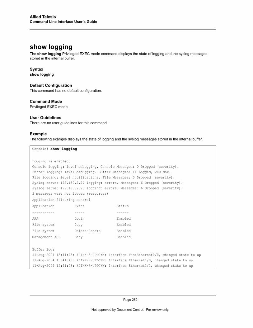
Allied Telesis Command Line Interface User’s Guide
show loggingThe show logging Privileged EXEC mode command displays the state of logging and the syslog messages stored in the internal buffer.
Syntaxshow logging
Default ConfigurationThis command has no default configuration.
Command ModePrivileged EXEC mode
User GuidelinesThere are no user guidelines for this command.
ExampleThe following example displays the state of logging and the syslog messages stored in the internal buffer.
Console# show logging
Logging is enabled.Console logging: level debugging. Console Messages: 0 Dropped (severity).
Buffer logging: level debugging. Buffer Messages: 11 Logged, 200 Max.
File logging: level notifications. File Messages: 0 Dropped (severity).Syslog server 192.180.2.27 logging: errors. Messages: 6 Dropped (severity).
Syslog server 192.180.2.28 logging: errors. Messages: 6 Dropped (severity).
2 messages were not logged (resources)
Application filtering control
Application Event Status
----------- ----- ------
AAA Login Enabled
File system Copy Enabled
File system Delete-Rename Enabled
Management ACL Deny Enabled
Buffer log:
11-Aug-2004 15:41:43: %LINK-3-UPDOWN: Interface FastEthernet0/0, changed state to up11-Aug-2004 15:41:43: %LINK-3-UPDOWN: Interface Ethernet1/0, changed state to up
11-Aug-2004 15:41:43: %LINK-3-UPDOWN: Interface Ethernet1/1, changed state to up
Page 252
Not approved by Document Control. For review only.
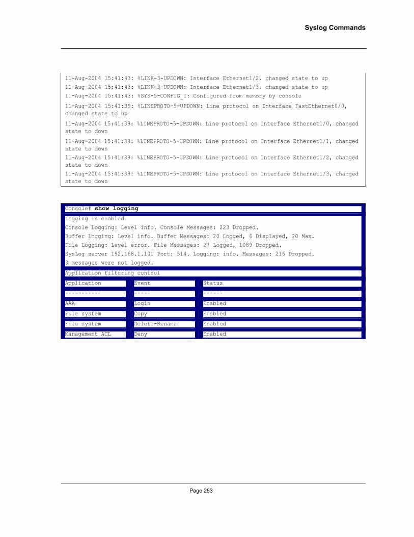
Syslog Commands
11-Aug-2004 15:41:43: %LINK-3-UPDOWN: Interface Ethernet1/2, changed state to up
11-Aug-2004 15:41:43: %LINK-3-UPDOWN: Interface Ethernet1/3, changed state to up11-Aug-2004 15:41:43: %SYS-5-CONFIG_I: Configured from memory by console
11-Aug-2004 15:41:39: %LINEPROTO-5-UPDOWN: Line protocol on Interface FastEthernet0/0, changed state to up
11-Aug-2004 15:41:39: %LINEPROTO-5-UPDOWN: Line protocol on Interface Ethernet1/0, changed state to down
11-Aug-2004 15:41:39: %LINEPROTO-5-UPDOWN: Line protocol on Interface Ethernet1/1, changed state to down
11-Aug-2004 15:41:39: %LINEPROTO-5-UPDOWN: Line protocol on Interface Ethernet1/2, changed state to down
11-Aug-2004 15:41:39: %LINEPROTO-5-UPDOWN: Line protocol on Interface Ethernet1/3, changed state to down
Console# show logging
Logging is enabled.
Console Logging: Level info. Console Messages: 223 Dropped.Buffer Logging: Level info. Buffer Messages: 20 Logged, 6 Displayed, 20 Max.
File Logging: Level error. File Messages: 27 Logged, 1089 Dropped.
SysLog server 192.168.1.101 Port: 514. Logging: info. Messages: 216 Dropped.3 messages were not logged.
Application filtering control
Application Event Status
----------- ----- ------
AAA Login Enabled
File system Copy Enabled
File system Delete-Rename Enabled
Management ACL Deny Enabled
Page 253
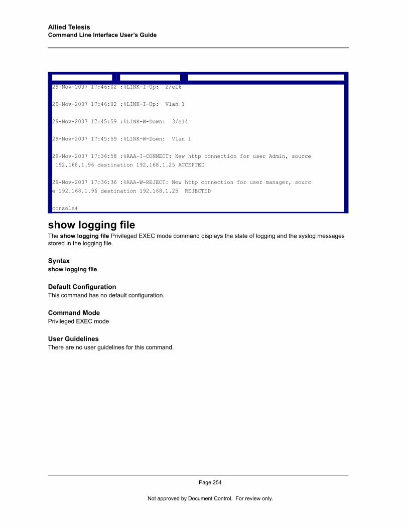
Allied Telesis Command Line Interface User’s Guide
show logging fileThe show logging file Privileged EXEC mode command displays the state of logging and the syslog messages stored in the logging file.
Syntaxshow logging file
Default ConfigurationThis command has no default configuration.
Command ModePrivileged EXEC mode
User GuidelinesThere are no user guidelines for this command.
29-Nov-2007 17:46:02 :%LINK-I-Up: 2/e16
29-Nov-2007 17:46:02 :%LINK-I-Up: Vlan 1
29-Nov-2007 17:45:59 :%LINK-W-Down: 3/e14
29-Nov-2007 17:45:59 :%LINK-W-Down: Vlan 1
29-Nov-2007 17:36:58 :%AAA-I-CONNECT: New http connection for user Admin, source
192.168.1.96 destination 192.168.1.25 ACCEPTED
29-Nov-2007 17:36:36 :%AAA-W-REJECT: New http connection for user manager, sourc
e 192.168.1.96 destination 192.168.1.25 REJECTED
console#
Page 254
Not approved by Document Control. For review only.
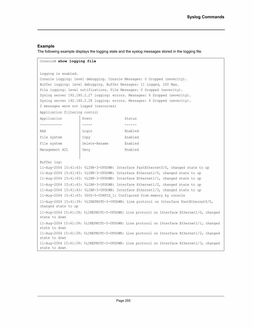
Syslog Commands
ExampleThe following example displays the logging state and the syslog messages stored in the logging file.
Console# show logging file
Logging is enabled.
Console logging: level debugging. Console Messages: 0 Dropped (severity).
Buffer logging: level debugging. Buffer Messages: 11 Logged, 200 Max.File logging: level notifications. File Messages: 0 Dropped (severity).
Syslog server 192.180.2.27 logging: errors. Messages: 6 Dropped (severity).
Syslog server 192.180.2.28 logging: errors. Messages: 6 Dropped (severity).2 messages were not logged (resources)
Application filtering control
Application Event Status
----------- ----- ------
AAA Login Enabled
File system Copy Enabled
File system Delete-Rename Enabled
Management ACL Deny Enabled
Buffer log:
11-Aug-2004 15:41:43: %LINK-3-UPDOWN: Interface FastEthernet0/0, changed state to up
11-Aug-2004 15:41:43: %LINK-3-UPDOWN: Interface Ethernet1/0, changed state to up11-Aug-2004 15:41:43: %LINK-3-UPDOWN: Interface Ethernet1/1, changed state to up
11-Aug-2004 15:41:43: %LINK-3-UPDOWN: Interface Ethernet1/2, changed state to up
11-Aug-2004 15:41:43: %LINK-3-UPDOWN: Interface Ethernet1/3, changed state to up
11-Aug-2004 15:41:43: %SYS-5-CONFIG_I: Configured from memory by console
11-Aug-2004 15:41:39: %LINEPROTO-5-UPDOWN: Line protocol on Interface FastEthernet0/0, changed state to up
11-Aug-2004 15:41:39: %LINEPROTO-5-UPDOWN: Line protocol on Interface Ethernet1/0, changed state to down
11-Aug-2004 15:41:39: %LINEPROTO-5-UPDOWN: Line protocol on Interface Ethernet1/1, changed state to down
11-Aug-2004 15:41:39: %LINEPROTO-5-UPDOWN: Line protocol on Interface Ethernet1/2, changed state to down
11-Aug-2004 15:41:39: %LINEPROTO-5-UPDOWN: Line protocol on Interface Ethernet1/3, changed state to down
Page 255

Allied Telesis Command Line Interface User’s Guide
show syslog-serversThe show syslog-servers Privileged EXEC mode command displays the settings of the syslog servers.
Syntaxshow syslog-servers
Default ConfigurationThis command has no default configuration.
Command ModePrivileged EXEC mode
User GuidelinesThere are no user guidelines for this command.
ExampleThe following example displays the settings of the syslog servers.
Console# show logging file
Logging is enabled.Console Logging: Level info. Console Messages: 226 Dropped.
Buffer Logging: Level info. Buffer Messages: 20 Logged, 6 Displayed, 20 Max.
File Logging: Level error. File Messages: 27 Logged, 1092 Dropped.SysLog server 192.168.1.101 Port: 514. Logging: info. Messages: 219 Dropped.
3 messages were not logged
Application filtering control
Application Event Status
----------- ----- ------
AAA Login Enabled
File system Copy Enabled
File system Delete-Rename Enabled
Management ACL Deny Enabled
29-Nov-2007 15:14:32 :%Box-E-STCK-EXCEP_HNDLR: Lost connection with unit 2 reaso
n 0x20097. Unit will be rebooted.
Console# show syslog-servers
Device Configuration
Page 256
Not approved by Document Control. For review only.

Syslog Commands
IP address Port Severity Facility Description
------------ ---- ------------- -------- -----------
192.180.2.27 514 Informational local7
192.180.2.28 514 Warning local7
Page 257
Allied Telesis Command Line Interface User’s Guide
Chapter 27.TACACS+ Commands
tacacs-server hostThe tacacs-server host Global Configuration mode command specifies a TACACS+ host. Use the no form of this command to delete the specified name or address.
Syntaxtacacs-server host {ip-address | hostname} [single-connection] [port port-number] [timeout timeout] [key key-string] [source source] [priority priority]
no tacacs-server host {ip-address | hostname}
Parameters• ip-address — IP address of the TACACS+ server. • hostname — Host name of the TACACS+ server. (Range: 1 - 158 characters)• single-connection — Indicates a single-connection. Rather than have the device open and close a TCP
connection to the daemon each time it must communicate, the single-connection option maintains a single open connection between the device and the daemon.
• port-number — Specifies a server port number. (Range: 0 - 65535)• timeout — Specifies the timeout value in seconds. (Range: 1 - 30)• key-string — Specifies the authentication and encryption key for all TACACS+ communications between the
device and the TACACS+ server. This key must match the encryption used on the TACACS+ daemon. To specify an empty string, enter "". (Range: 0 - 128 characters)
• source — Specifies the source IP address to use for the communication. 0.0.0.0 indicates a request to use the IP address of the outgoing IP interface.
• priority — Determines the order in which the TACACS+ servers are used, where 0 is the highest priority. (Range: 0 - 65535)
Default ConfigurationNo TACACS+ host is specified.
If no port number is specified, default port number 49 is used.
If no host-specific timeout, key-string or source value is specified, the global value is used.
If no TACACS+ server priority is specified, default priority 0 is used.
Command ModeGlobal Configuration mode
User GuidelinesMultiple tacacs-server host commands can be used to specify multiple hosts.
Page 258
Not approved by Document Control. For review only.
TACACS+ Commands
ExampleThe following example specifies a TACACS+ host.
tacacs-server keyThe tacacs-server key Global Configuration mode command sets the authentication encryption key used for all TACACS+ communications between the device and the TACACS+ daemon. Use the no form of this command to disable the key.
Syntaxtacacs-server key key-string
no tacacs-server key
Parameters• key-string — Specifies the authentication and encryption key for all TACACS+ communications between the
device and the TACACS+ server. This key must match the encryption used on the TACACS+ daemon. (Range: 0-128 characters)
Default ConfigurationEmpty string.
Command ModeGlobal Configuration mode
User GuidelinesThere are no user guidelines for this command.
ExampleThe following example sets the authentication encryption key.
tacacs-server timeoutThe tacacs-server timeout Global Configuration mode command sets the interval during which the device waits for a TACACS+ server to reply. Use the no form of this command to return to the default configuration.
Syntaxtacacs-server timeout timeout
no tacacs-server timeout
Parameters• timeout — Specifies the timeout value in seconds. (Range: 1 - 30)
Console(config)# tacacs-server host 172.16.1.1
Console(config)# tacacs-server key ati-s
Page 259

Allied Telesis Command Line Interface User’s Guide
Default Configuration5 seconds
Command ModeGlobal Configuration mode
User GuidelinesThere are no user guidelines for this command.
ExampleThe following example sets the timeout value to 30.
tacacs-server source-ipThe tacacs-server source-ip Global Configuration mode command configures the source IP address to be used for communication with TACACS+ servers. Use the no form of this command to return to the default configuration.
Syntaxtacacs-server source-ip source
no tacacs-server source-ip source
Parameters• source — Specifies the source IP address.
Default ConfigurationThe source IP address is the address of the outgoing IP interface.
Command ModeGlobal Configuration mode
User GuidelinesN/A
ExampleThe following example specifies the source IP address.
show tacacsThe show tacacs Privileged EXEC mode command displays configuration and statistical information about a TACACS+ server.
Console(config)# tacacs-server timeout 30
Console(config)# tacacs-server source-ip 172.16.8.1
Page 260
Not approved by Document Control. For review only.
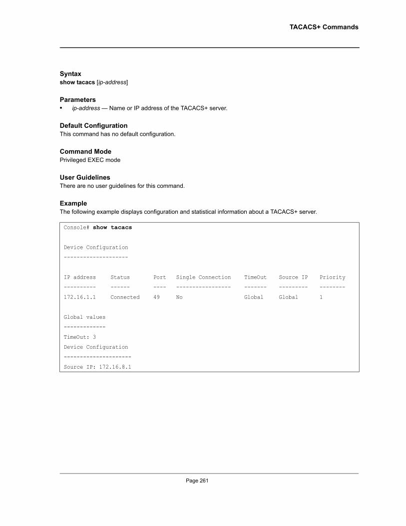
TACACS+ Commands
Syntaxshow tacacs [ip-address]
Parameters• ip-address — Name or IP address of the TACACS+ server.
Default ConfigurationThis command has no default configuration.
Command ModePrivileged EXEC mode
User GuidelinesThere are no user guidelines for this command.
ExampleThe following example displays configuration and statistical information about a TACACS+ server.
Console# show tacacs
Device Configuration
--------------------
IP address Status Port Single Connection TimeOut Source IP Priority
---------- ------ ---- ----------------- ------- --------- --------
172.16.1.1 Connected 49 No Global Global 1
Global values
-------------
TimeOut: 3
Device Configuration
---------------------
Source IP: 172.16.8.1
Page 261
Allied Telesis Command Line Interface User’s Guide
Chapter 28.System Management Commands
pingThe ping User EXEC mode command sends ICMP echo request packets to another node on the network.
Syntaxping {ip-address | hostname } [size packet_size] [count packet_count] [timeout time_out]
Parameters• ip-address — IP address to ping.• hostname — Host name to ping. (Range: 1-158 characters)• packet_size — Number of bytes in a packet. The actual packet size is eight bytes larger than the specified
size specified because the device adds header information. (Range: 56 - 1472 bytes)• packet_count — Number of packets to send. If 0 is entered, it pings until stopped. (Range: 0-65535 packets)• time_out — Timeout in milliseconds to wait for each reply. (Range: 50 - 65535 milliseconds)
Default ConfigurationDefault packet size is 56 bytes.
Default number of packets to send is 4.
Default timeout value is 2000 milliseconds.
Command ModeUser EXEC mode
User Guidelines• The hostname must be a fully qualified DNS name. A fully qualified DNS name has a period at the end.• Press Esc to stop pinging.• Following are examples of unsuccessful pinging:
– Destination does not respond. If the host does not respond, a “no answer from host” appears in ten seconds.
– Destination unreachable. The gateway for this destination indicates that the destination is unreachable.– Network or host unreachable. The device found no corresponding entry in the route table.
Page 262
Not approved by Document Control. For review only.
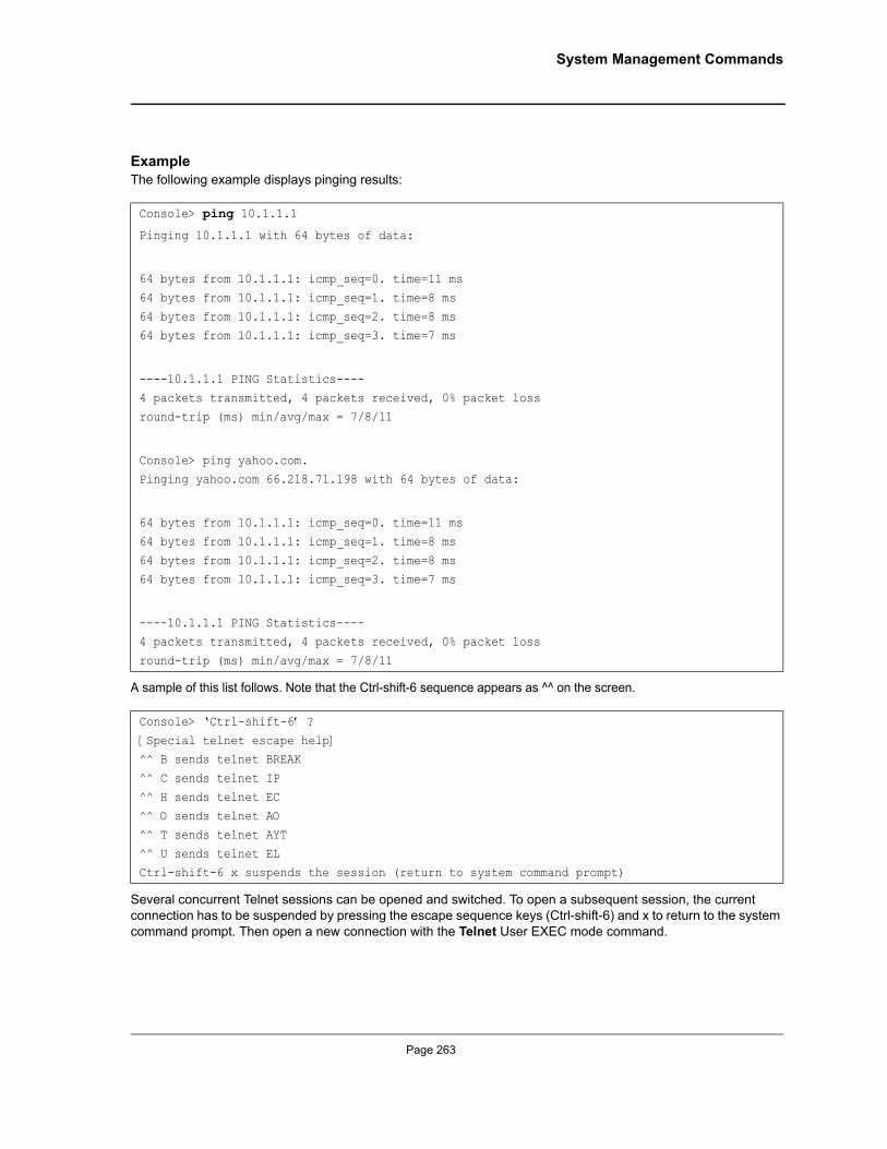
System Management Commands
ExampleThe following example displays pinging results:
A sample of this list follows. Note that the Ctrl-shift-6 sequence appears as ^^ on the screen.
Several concurrent Telnet sessions can be opened and switched. To open a subsequent session, the current connection has to be suspended by pressing the escape sequence keys (Ctrl-shift-6) and x to return to the system command prompt. Then open a new connection with the Telnet User EXEC mode command.
Console> ping 10.1.1.1
Pinging 10.1.1.1 with 64 bytes of data:
64 bytes from 10.1.1.1: icmp_seq=0. time=11 ms
64 bytes from 10.1.1.1: icmp_seq=1. time=8 ms
64 bytes from 10.1.1.1: icmp_seq=2. time=8 ms64 bytes from 10.1.1.1: icmp_seq=3. time=7 ms
----10.1.1.1 PING Statistics----
4 packets transmitted, 4 packets received, 0% packet loss
round-trip (ms) min/avg/max = 7/8/11
Console> ping yahoo.com. Pinging yahoo.com 66.218.71.198 with 64 bytes of data:
64 bytes from 10.1.1.1: icmp_seq=0. time=11 ms
64 bytes from 10.1.1.1: icmp_seq=1. time=8 ms
64 bytes from 10.1.1.1: icmp_seq=2. time=8 ms64 bytes from 10.1.1.1: icmp_seq=3. time=7 ms
----10.1.1.1 PING Statistics----
4 packets transmitted, 4 packets received, 0% packet loss
round-trip (ms) min/avg/max = 7/8/11
Console> ‘Ctrl-shift-6’ ?
[Special telnet escape help] ^^ B sends telnet BREAK
^^ C sends telnet IP
^^ H sends telnet EC ^^ O sends telnet AO
^^ T sends telnet AYT
^^ U sends telnet EL Ctrl-shift-6 x suspends the session (return to system command prompt)
Page 263
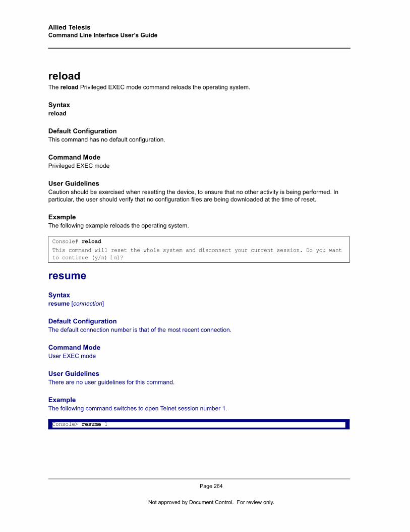
Allied Telesis Command Line Interface User’s Guide
reloadThe reload Privileged EXEC mode command reloads the operating system.
Syntaxreload
Default ConfigurationThis command has no default configuration.
Command ModePrivileged EXEC mode
User GuidelinesCaution should be exercised when resetting the device, to ensure that no other activity is being performed. In particular, the user should verify that no configuration files are being downloaded at the time of reset.
ExampleThe following example reloads the operating system.
resumeSyntaxresume [connection]
Default ConfigurationThe default connection number is that of the most recent connection.
Command ModeUser EXEC mode
User GuidelinesThere are no user guidelines for this command.
ExampleThe following command switches to open Telnet session number 1.
Console# reloadThis command will reset the whole system and disconnect your current session. Do you want to continue (y/n) [n]?
Console> resume 1
Page 264
Not approved by Document Control. For review only.
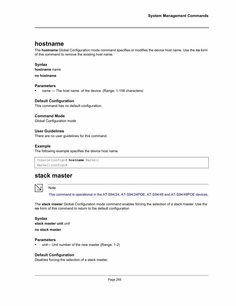
System Management Commands
hostnameThe hostname Global Configuration mode command specifies or modifies the device host name. Use the no form of this command to remove the existing host name.
Syntaxhostname name
no hostname
Parameters• name — The host name. of the device. (Range: 1-158 characters)
Default ConfigurationThis command has no default configuration.
Command ModeGlobal Configuration mode
User GuidelinesThere are no user guidelines for this command.
ExampleThe following example specifies the device host name.
stack master
Note
This command is operational in the AT-S94/24, AT-S94/24POE, AT-S94/48 and AT-S94/48POE devices.
The stack master Global Configuration mode command enables forcing the selection of a stack master. Use the no form of this command to return to the default configuration.
Syntaxstack master unit unit
no stack master
Parameters• unit— Unit number of the new master (Range: 1-2)
Default ConfigurationDisables forcing the selection of a stack master.
Console(config)# hostname MarvellMarvell(config)#
Page 265
Allied Telesis Command Line Interface User’s Guide
Command ModeGlobal Configuration mode
User GuidelinesThis command is not relevant to standalone devices.
The following algorithm is used to select a unit as the master:
• If only one master-enabled unit is in the stack (1 or 2), it becomes the master.• If a unit configured as a forced master, it becomes the master. If a forced master unit is removed from a stack and placed in a different stack with another forced master unit, both are considered to be forced, and the election criteria continue as follows:
• The unit with the longer up-time is elected master. Units are considered to have the same up-time if they were powered up within ten minutes of each other.
• If both forced master units have the same up-time, Unit 1 is elected.
ExampleThe following example selects Unit 2 as the stack master.
stack reload
Note
This command is operational in the AT-S94/24, AT-S94/24POE, AT-S94/48 and AT-S94/48POE devices.
The stack reload Privileged EXEC mode command reloads stack members.
Syntaxstack reload [unit unit]
Parameters• unit— Number of the unit to be reloaded (Range: 1-6)
Default ConfigurationAll units are reloaded.
Command Modes Privileged EXEC mode
User GuidelinesThis command is not relevant to standalone devices.
If no unit is specified, all units are reloaded.
Console(config)# stack master unit 2
Page 266
Not approved by Document Control. For review only.
System Management Commands
ExampleThe following example reloads Unit 2 of the stack.
stack change unit-id
Note
This command is operational in the AT-S94/24, AT-S94/24POE, AT-S94/48 and AT-S94/48POE devices.
The stack change unit-id Global Configuration mode command is used to change the Unit ID of a specific unit.
Syntaxstack change unit-id unit-number to new-unit-number
Parameters• unit-number— Specifies the current number of the unit. (Range: 1-6)• new-unit-number— Specifies the new number of the unit. (Range: 1-6)
Default ConfigurationThe automatically configured unit number is assigned.
Command Modes Global Configuration mode
User GuidelinesThis command is not relevant to standalone devices.
The command takes effect only after resetting the device.
ExampleThis example changes Unit Number 6 to Unit Number 5. The command takes effect only after resetting the device.
show stack
Note
This command is operational in the AT-S94/24, AT-S94/24POE, AT-S94/48 and AT-S94/48POE devices.
The show stack User EXEC mode command displays information about the status of a stack.
Console(config)# stack reload unit 2
Console# configConsole(config)# stack change unit-id 6 to 5
Page 267
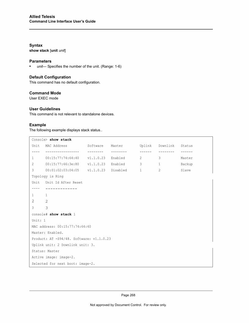
Allied Telesis Command Line Interface User’s Guide
Syntaxshow stack [unit unit]
Parameters• unit— Specifies the number of the unit. (Range: 1-6)
Default ConfigurationThis command has no default configuration.
Command ModeUser EXEC mode
User GuidelinesThis command is not relevant to standalone devices.
ExampleThe following example displays stack status..
Console> show stack
Unit MAC Address Software Master Uplink Downlink Status
---- ----------------- -------- -------- ------ -------- ------
1 00:15:77:74:64:40 v1.1.0.23 Enabled 2 3 Master
2 00:15:77:66:3e:80 v1.1.0.23 Enabled 3 1 Backup
3 00:01:02:03:04:05 v1.1.0.23 Disabled 1 2 Slave
Topology is Ring
Unit Unit Id After Reset
---- -------------
1 1
2 2
3 3
console# show stack 1
Unit: 1
MAC address: 00:15:77:74:64:40
Master: Enabled.
Product: AT -S94/48. Software: v1.1.0.23
Uplink unit: 2 Downlink unit: 3.
Status: Master
Active image: image-2.
Selected for next boot: image-2.
Page 268
Not approved by Document Control. For review only.
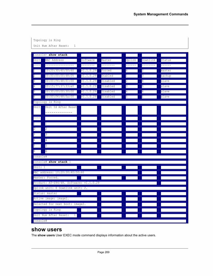
System Management Commands
show usersThe show users User EXEC mode command displays information about the active users.
Topology is Ring
Unit Num After Reset: 1
Console> show stack
Unit MAC Address Software Master Uplink Downlink Status
---- ----------------- -------- -------- ------ -------- ------
1 10:20:30:40:50:60 v1.1.0.29 Forced 6 2 master
2 00:00:00:00:48:05 v1.1.0.29 Enabled 1 3 backup
3 00:00:f4:48:01:00 v1.1.0.29 Disabled 2 4 slave
4 00:15:77:37:33:e0 v1.1.0.29 Disabled 3 5 slave
5 00:30:00:00:30:00 v1.1.0.29 Disabled 4 6 slave
6 00:00:f4:48:0a:00 v1.1.0.29 Disabled 5 1 slave
Topology is Ring
Unit Unit Id After Reset
-------------
----
1 1
2 2
3 3
4 4
5 5
6 6
console#
console# show stack 1
Unit: 1
MAC address: 10:20:30:40:50:60
Master: Forced.
Product: AT-S94/48. Software: v1.1.0.29
Uplink unit: 6 Downlink unit: 2.
Status: master
Active image: image2.
Selected for next boot: image2.
Topology is Ring
Unit Num After Reset: 1
console#
Page 269
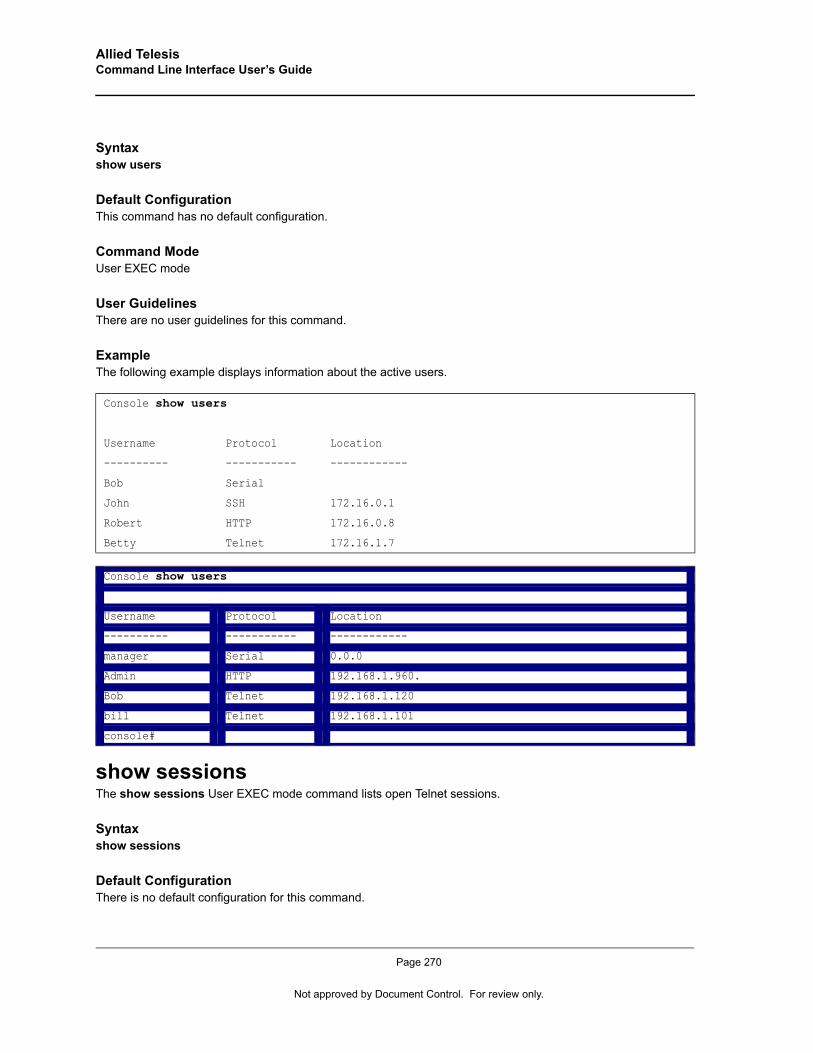
Allied Telesis Command Line Interface User’s Guide
Syntaxshow users
Default ConfigurationThis command has no default configuration.
Command ModeUser EXEC mode
User GuidelinesThere are no user guidelines for this command.
ExampleThe following example displays information about the active users.
show sessionsThe show sessions User EXEC mode command lists open Telnet sessions.
Syntaxshow sessions
Default ConfigurationThere is no default configuration for this command.
Console show users
Username Protocol Location
---------- ----------- ------------
Bob Serial
John SSH 172.16.0.1
Robert HTTP 172.16.0.8
Betty Telnet 172.16.1.7
Console show users
Username Protocol Location
---------- ----------- ------------
manager Serial 0.0.0
Admin HTTP 192.168.1.960.
Bob Telnet 192.168.1.120
bill Telnet 192.168.1.101
console#
Page 270
Not approved by Document Control. For review only.
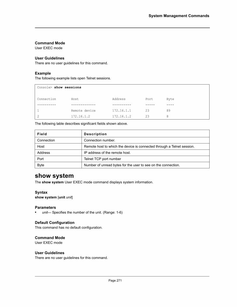
System Management Commands
Command ModeUser EXEC mode
User GuidelinesThere are no user guidelines for this command.
Example The following example lists open Telnet sessions.
The following table describes significant fields shown above.
show system The show system User EXEC mode command displays system information.
Syntaxshow system [unit unit]
Parameters• unit— Specifies the number of the unit. (Range: 1-6)
Default ConfigurationThis command has no default configuration.
Command ModeUser EXEC mode
User GuidelinesThere are no user guidelines for this command.
Console> show sessions
Connection Host Address Port Byte
---------- ------------- ---------- ----- ----
1 Remote device 172.16.1.1 23 89
2 172.16.1.2 172.16.1.2 23 8
Field Description
Connection Connection number.
Host Remote host to which the device is connected through a Telnet session.
Address IP address of the remote host.
Port Telnet TCP port number
Byte Number of unread bytes for the user to see on the connection.
Page 271
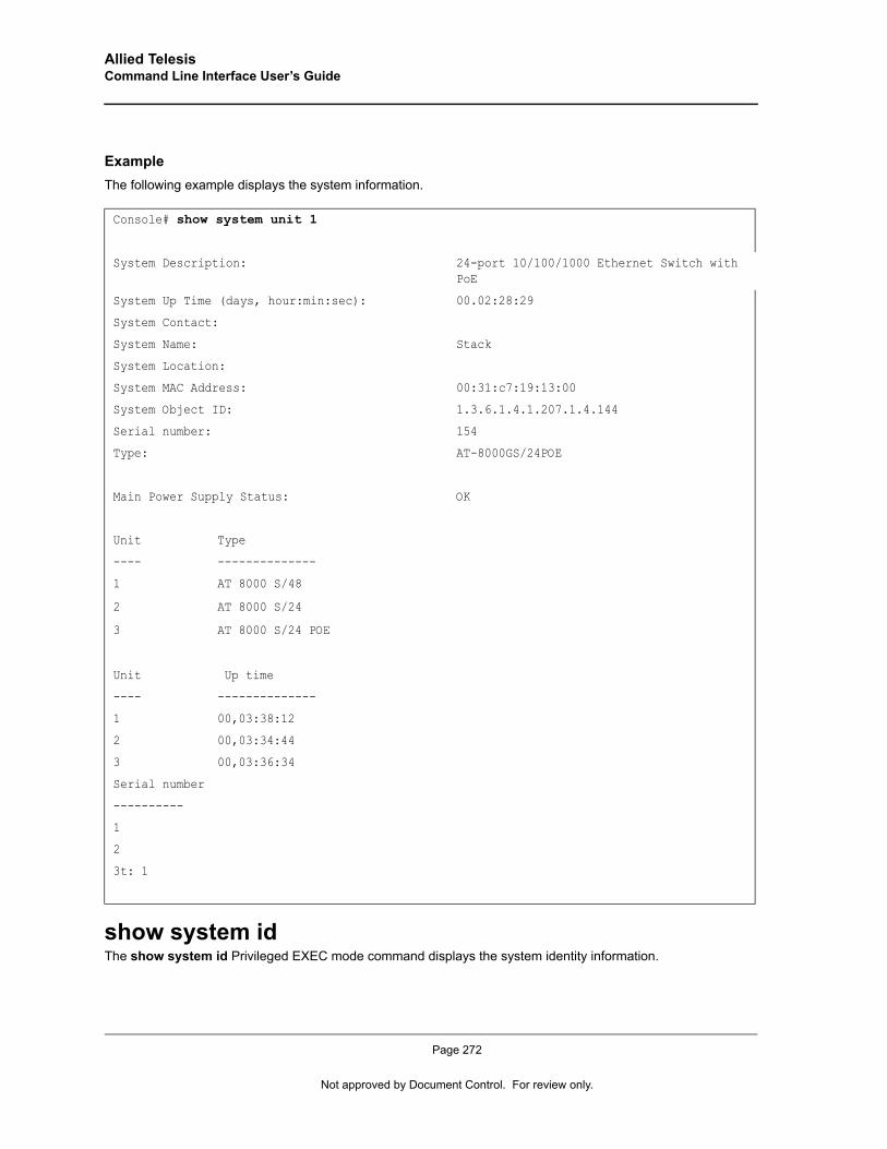
Allied Telesis Command Line Interface User’s Guide
ExampleThe following example displays the system information.
show system idThe show system id Privileged EXEC mode command displays the system identity information.
Console# show system unit 1
System Description: 24-port 10/100/1000 Ethernet Switch with PoE
System Up Time (days, hour:min:sec): 00.02:28:29
System Contact:
System Name: Stack
System Location:
System MAC Address: 00:31:c7:19:13:00
System Object ID: 1.3.6.1.4.1.207.1.4.144
Serial number: 154
Type: AT-8000GS/24POE
Main Power Supply Status: OK
Unit Type
---- --------------
1 AT 8000 S/48
2 AT 8000 S/24
3 AT 8000 S/24 POE
Unit Up time
---- --------------
1 00,03:38:12
2 00,03:34:44
3 00,03:36:34
Serial number
----------
1
2
3t: 1
Page 272
Not approved by Document Control. For review only.
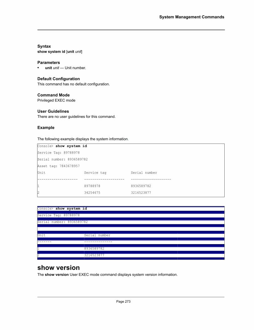
System Management Commands
Syntaxshow system id [unit unit]
Parameters• unit unit — Unit number.
Default ConfigurationThis command has no default configuration.
Command ModePrivileged EXEC mode
User GuidelinesThere are no user guidelines for this command.
Example
The following example displays the system information.
show versionThe show version User EXEC mode command displays system version information.
Console> show system id
Service Tag: 89788978
Serial number: 8936589782
Asset tag: 7843678957
Unit Service tag Serial number
-------------------- -------------------- --------------------
1 89788978 8936589782
2 34254675 3216523877
Console> show system id
Service Tag: 89788978
Serial number: 8936589782
Unit Serial number
------- --------------
1 8936589782
2 3216523877
Page 273
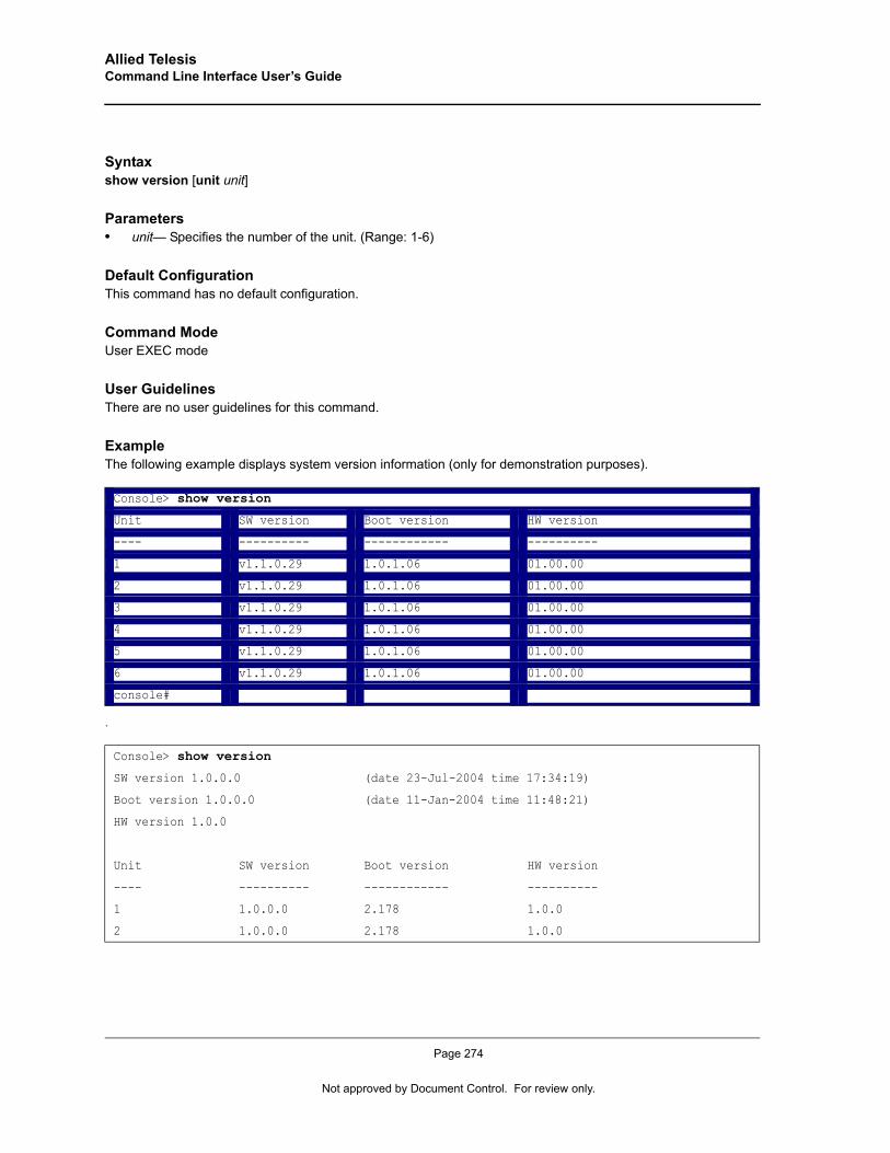
Allied Telesis Command Line Interface User’s Guide
Syntaxshow version [unit unit]
Parameters• unit— Specifies the number of the unit. (Range: 1-6)
Default ConfigurationThis command has no default configuration.
Command ModeUser EXEC mode
User GuidelinesThere are no user guidelines for this command.
ExampleThe following example displays system version information (only for demonstration purposes).
.
Console> show version
Unit SW version Boot version HW version
---- ---------- ------------ ----------
1 v1.1.0.29 1.0.1.06 01.00.00
2 v1.1.0.29 1.0.1.06 01.00.00
3 v1.1.0.29 1.0.1.06 01.00.00
4 v1.1.0.29 1.0.1.06 01.00.00
5 v1.1.0.29 1.0.1.06 01.00.00
6 v1.1.0.29 1.0.1.06 01.00.00
console#
Console> show version
SW version 1.0.0.0 (date 23-Jul-2004 time 17:34:19)
Boot version 1.0.0.0 (date 11-Jan-2004 time 11:48:21)
HW version 1.0.0
Unit SW version Boot version HW version
---- ---------- ------------ ----------
1 1.0.0.0 2.178 1.0.0
2 1.0.0.0 2.178 1.0.0
Page 274
Not approved by Document Control. For review only.
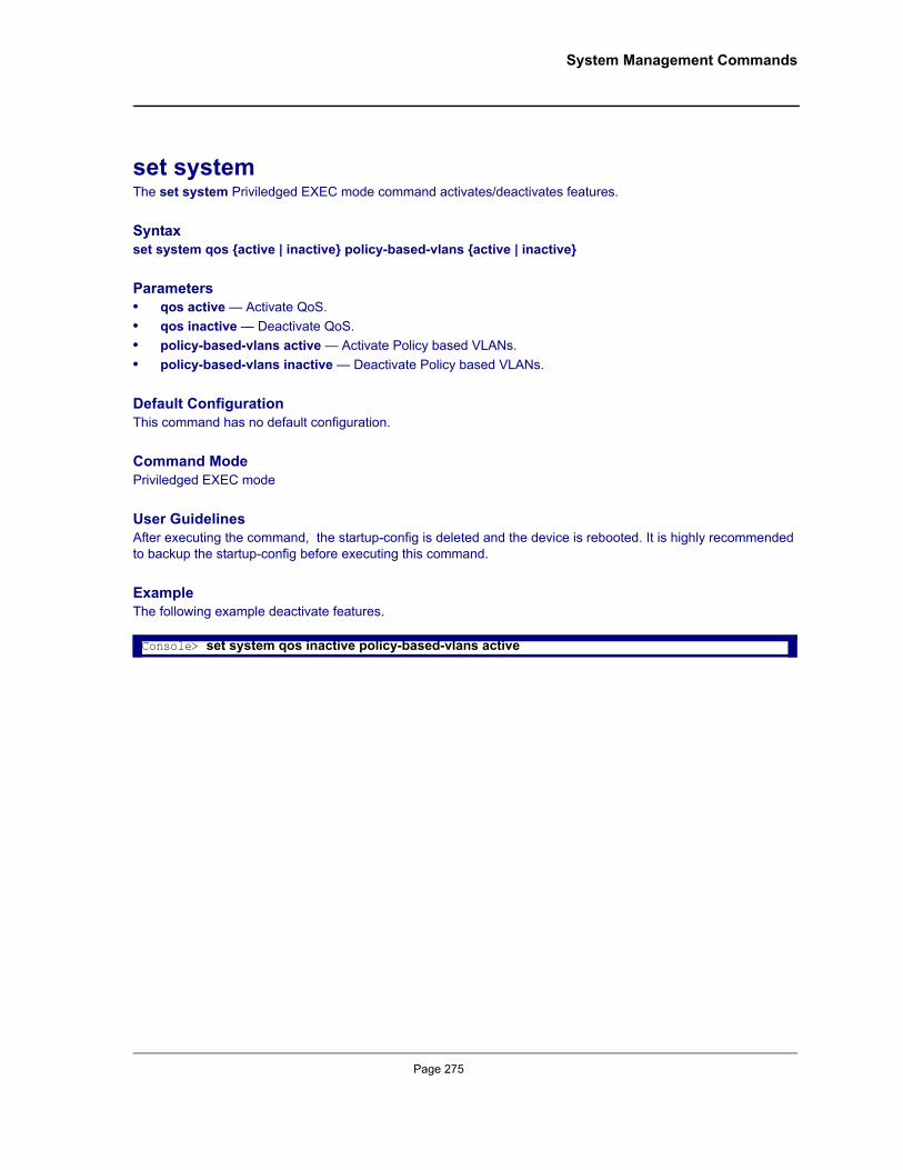
System Management Commands
set systemThe set system Priviledged EXEC mode command activates/deactivates features.
Syntaxset system qos {active | inactive} policy-based-vlans {active | inactive}
Parameters• qos active — Activate QoS.• qos inactive — Deactivate QoS.• policy-based-vlans active — Activate Policy based VLANs.• policy-based-vlans inactive — Deactivate Policy based VLANs.
Default ConfigurationThis command has no default configuration.
Command ModePriviledged EXEC mode
User GuidelinesAfter executing the command, the startup-config is deleted and the device is rebooted. It is highly recommended to backup the startup-config before executing this command.
ExampleThe following example deactivate features.
Console> set system qos inactive policy-based-vlans active
Page 275
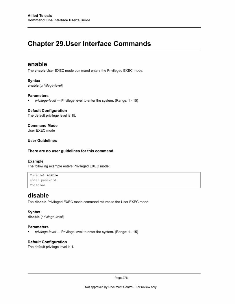
Allied Telesis Command Line Interface User’s Guide
Chapter 29.User Interface Commands
enableThe enable User EXEC mode command enters the Privileged EXEC mode.
Syntaxenable [privilege-level]
Parameters• privilege-level — Privilege level to enter the system. (Range: 1 - 15)
Default ConfigurationThe default privilege level is 15.
Command ModeUser EXEC mode
User Guidelines
There are no user guidelines for this command.
ExampleThe following example enters Privileged EXEC mode:
disableThe disable Privileged EXEC mode command returns to the User EXEC mode.
Syntaxdisable [privilege-level]
Parameters• privilege-level — Privilege level to enter the system. (Range: 1 - 15)
Default ConfigurationThe default privilege level is 1.
Console> enableenter password:
Console#
Page 276
Not approved by Document Control. For review only.
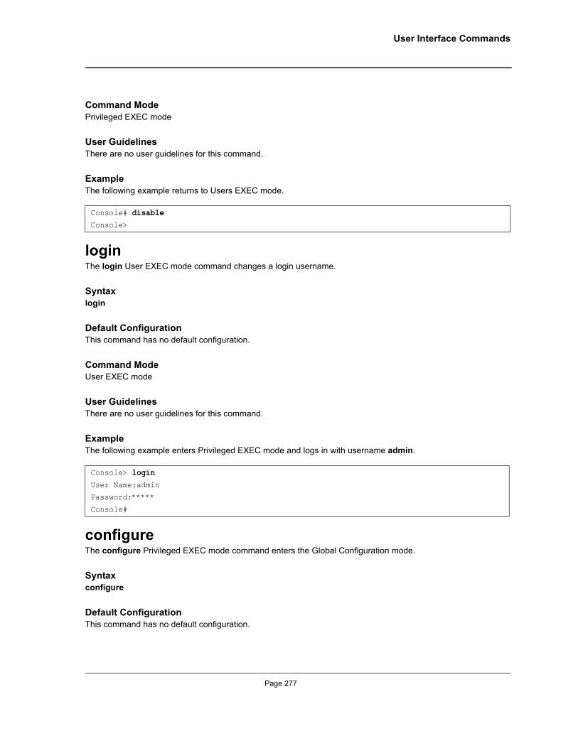
User Interface Commands
Command ModePrivileged EXEC mode
User GuidelinesThere are no user guidelines for this command.
ExampleThe following example returns to Users EXEC mode.
loginThe login User EXEC mode command changes a login username.
Syntaxlogin
Default ConfigurationThis command has no default configuration.
Command ModeUser EXEC mode
User GuidelinesThere are no user guidelines for this command.
ExampleThe following example enters Privileged EXEC mode and logs in with username admin.
configureThe configure Privileged EXEC mode command enters the Global Configuration mode.
Syntaxconfigure
Default ConfigurationThis command has no default configuration.
Console# disableConsole>
Console> loginUser Name:adminPassword:*****
Console#
Page 277
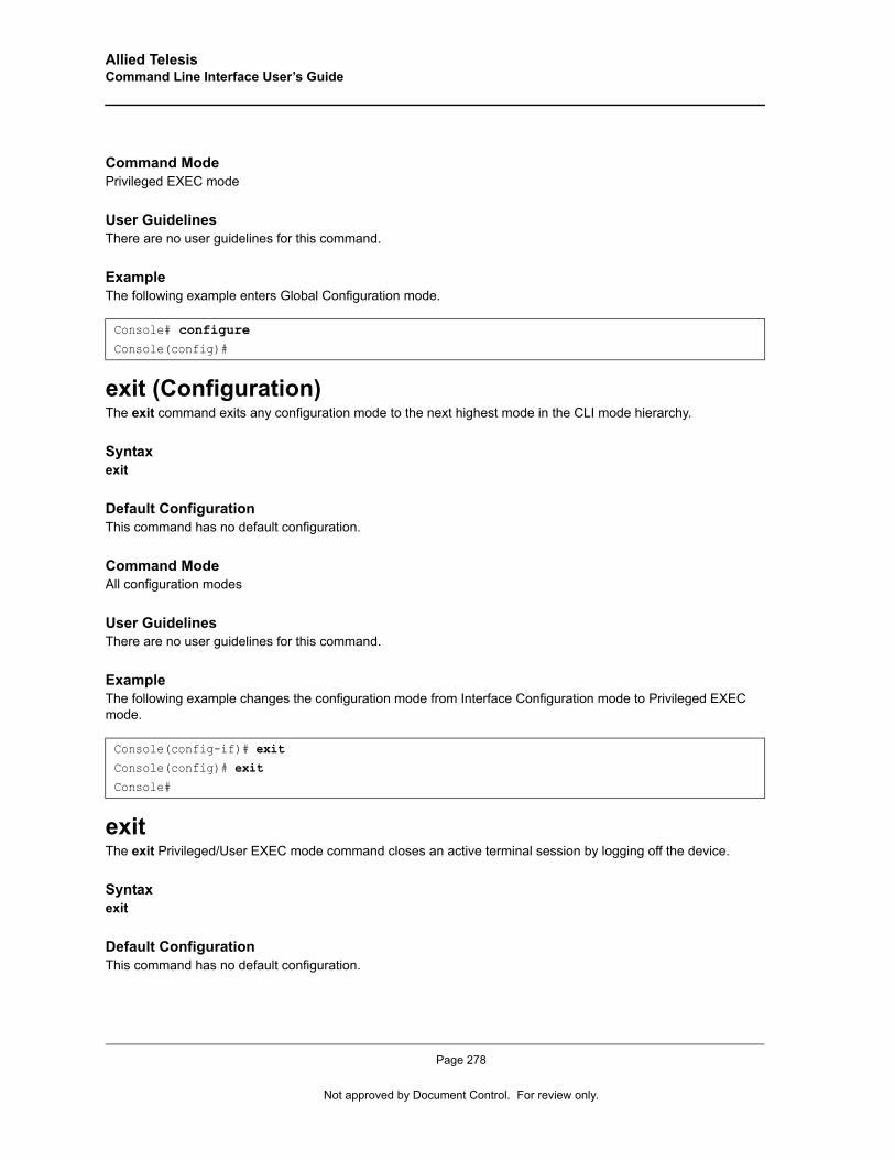
Allied Telesis Command Line Interface User’s Guide
Command ModePrivileged EXEC mode
User GuidelinesThere are no user guidelines for this command.
ExampleThe following example enters Global Configuration mode.
exit (Configuration)The exit command exits any configuration mode to the next highest mode in the CLI mode hierarchy.
Syntaxexit
Default ConfigurationThis command has no default configuration.
Command ModeAll configuration modes
User GuidelinesThere are no user guidelines for this command.
ExampleThe following example changes the configuration mode from Interface Configuration mode to Privileged EXEC mode.
exitThe exit Privileged/User EXEC mode command closes an active terminal session by logging off the device.
Syntaxexit
Default ConfigurationThis command has no default configuration.
Console# configureConsole(config)#
Console(config-if)# exitConsole(config)# exitConsole#
Page 278
Not approved by Document Control. For review only.
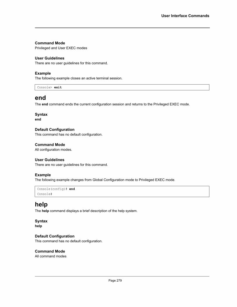
User Interface Commands
Command ModePrivileged and User EXEC modes
User GuidelinesThere are no user guidelines for this command.
ExampleThe following example closes an active terminal session.
endThe end command ends the current configuration session and returns to the Privileged EXEC mode.
Syntaxend
Default ConfigurationThis command has no default configuration.
Command ModeAll configuration modes.
User GuidelinesThere are no user guidelines for this command.
ExampleThe following example changes from Global Configuration mode to Privileged EXEC mode.
helpThe help command displays a brief description of the help system.
Syntaxhelp
Default ConfigurationThis command has no default configuration.
Command ModeAll command modes
Console> exit
Console(config)# endConsole#
Page 279
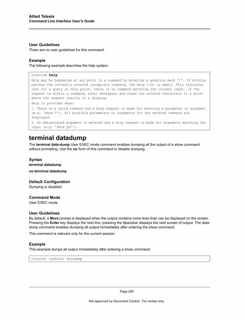
Allied Telesis Command Line Interface User’s Guide
User GuidelinesThere are no user guidelines for this command.
ExampleThe following example describes the help system.
terminal datadumpThe terminal data-dump User EXEC mode command enables dumping all the output of a show command without prompting. Use the no form of this command to disable dumping.
Syntaxterminal datadump
no terminal datadump
Default ConfigurationDumping is disabled.
Command ModeUser EXEC mode
User GuidelinesBy default, a More prompt is displayed when the output contains more lines than can be displayed on the screen. Pressing the Enter key displays the next line; pressing the Spacebar displays the next screen of output. The data-dump command enables dumping all output immediately after entering the show command.
This command is relevant only for the current session.
ExampleThis example dumps all output immediately after entering a show command.
Console# helpHelp may be requested at any point in a command by entering a question mark '?'. If nothing matches the currently entered incomplete command, the help list is empty. This indicates that for a query at this point, there is no command matching the current input. If the request is within a command, enter backspace and erase the entered characters to a point where the request results in a display.
Help is provided when:
1. There is a valid command and a help request is made for entering a parameter or argument (e.g. 'show ?'). All possible parameters or arguments for the entered command are displayed.
2. An abbreviated argument is entered and a help request is made for arguments matching the input (e.g. 'show pr?').
Console> terminal datadump
Page 280
Not approved by Document Control. For review only.
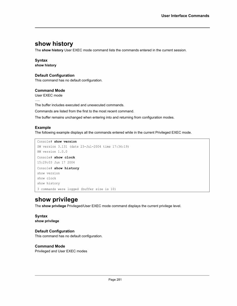
User Interface Commands
show historyThe show history User EXEC mode command lists the commands entered in the current session.
Syntaxshow history
Default ConfigurationThis command has no default configuration.
Command ModeUser EXEC modeUser Guidelines
The buffer includes executed and unexecuted commands.
Commands are listed from the first to the most recent command.
The buffer remains unchanged when entering into and returning from configuration modes.
ExampleThe following example displays all the commands entered while in the current Privileged EXEC mode.
show privilegeThe show privilege Privileged/User EXEC mode command displays the current privilege level.
Syntaxshow privilege
Default ConfigurationThis command has no default configuration.
Command ModePrivileged and User EXEC modes
Console# show versionSW version 3.131 (date 23-Jul-2004 time 17:34:19)
HW version 1.0.0
Console# show clock15:29:03 Jun 17 2004
Console# show historyshow version
show clockshow history
3 commands were logged (buffer size is 10)
Page 281
Allied Telesis Command Line Interface User’s Guide
User GuidelinesThere are no user guidelines for this command.
ExampleThe following example displays the current privilege level for the Privileged EXEC mode.
Console# show privilegeCurrent privilege level is 15
Page 282
Not approved by Document Control. For review only.
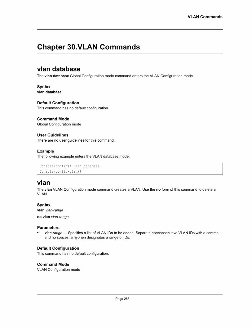
VLAN Commands
Chapter 30.VLAN Commands
vlan databaseThe vlan database Global Configuration mode command enters the VLAN Configuration mode.
Syntaxvlan database
Default ConfigurationThis command has no default configuration.
Command ModeGlobal Configuration mode
User GuidelinesThere are no user guidelines for this command.
ExampleThe following example enters the VLAN database mode.
vlanThe vlan VLAN Configuration mode command creates a VLAN. Use the no form of this command to delete a VLAN.
Syntaxvlan vlan-range
no vlan vlan-range
Parameters• vlan-range — Specifies a list of VLAN IDs to be added. Separate nonconsecutive VLAN IDs with a comma
and no spaces; a hyphen designates a range of IDs.
Default ConfigurationThis command has no default configuration.
Command ModeVLAN Configuration mode
Console(config)# vlan database
Console(config-vlan)#
Page 283
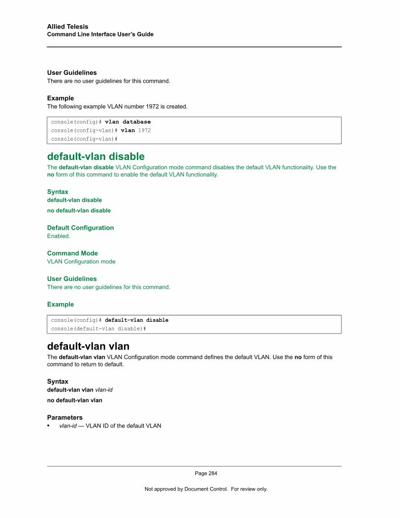
Allied Telesis Command Line Interface User’s Guide
User GuidelinesThere are no user guidelines for this command.
ExampleThe following example VLAN number 1972 is created.
default-vlan disableThe default-vlan disable VLAN Configuration mode command disables the default VLAN functionality. Use the no form of this command to enable the default VLAN functionality.
Syntaxdefault-vlan disable
no default-vlan disable
Default ConfigurationEnabled.
Command ModeVLAN Configuration mode
User GuidelinesThere are no user guidelines for this command.
Example
default-vlan vlanThe default-vlan vlan VLAN Configuration mode command defines the default VLAN. Use the no form of this command to return to default.
Syntaxdefault-vlan vlan vlan-id
no default-vlan vlan
Parameters• vlan-id — VLAN ID of the default VLAN
console(config)# vlan databaseconsole(config-vlan)# vlan 1972console(config-vlan)#
console(config)# default-vlan disableconsole(default-vlan disable)#
Page 284
Not approved by Document Control. For review only.

VLAN Commands
Default Configuration1
Command ModeVLAN Configuration mode
User GuidelinesThere are no user guidelines for this command.
Note
After running the command, the device must be reset.
Example
interface vlanThe interface vlan Global Configuration mode command enters the Interface Configuration (VLAN) mode.
Syntaxinterface vlan vlan-id
Parameters• vlan-id — Specifies an existing VLAN ID.
Default ConfigurationThis command has no default configuration.
Command ModeGlobal Configuration mode
User GuidelinesIn case the VLAN doesn't exist (‘ghost VLAN’), only partial list of the commands are available under the interface VLAN context.
The commands supported for non-existant VLANs are:
1) IGMP snooping control
2) Bridge Multicast configuration
console(config-vlan)# default-vlan vlan 1console(config-vlan)#
Page 285
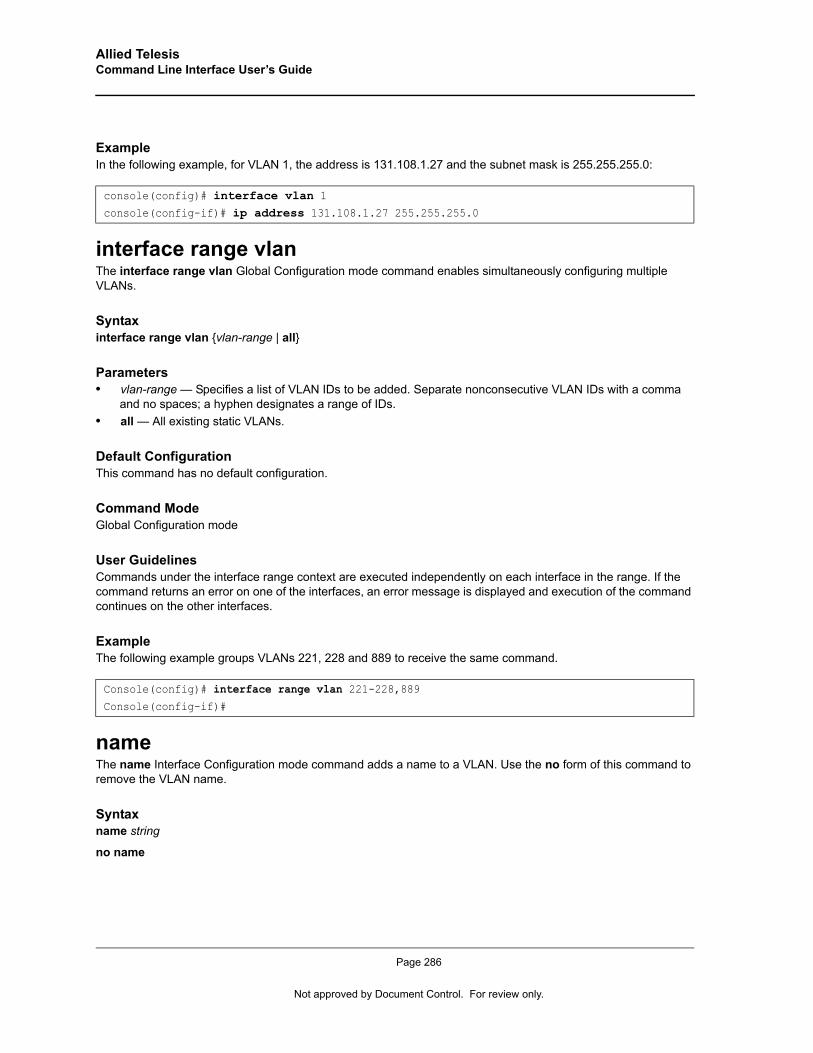
Allied Telesis Command Line Interface User’s Guide
ExampleIn the following example, for VLAN 1, the address is 131.108.1.27 and the subnet mask is 255.255.255.0:
interface range vlanThe interface range vlan Global Configuration mode command enables simultaneously configuring multiple VLANs.
Syntaxinterface range vlan {vlan-range | all}
Parameters• vlan-range — Specifies a list of VLAN IDs to be added. Separate nonconsecutive VLAN IDs with a comma
and no spaces; a hyphen designates a range of IDs.• all — All existing static VLANs.
Default ConfigurationThis command has no default configuration.
Command ModeGlobal Configuration mode
User GuidelinesCommands under the interface range context are executed independently on each interface in the range. If the command returns an error on one of the interfaces, an error message is displayed and execution of the command continues on the other interfaces.
ExampleThe following example groups VLANs 221, 228 and 889 to receive the same command.
nameThe name Interface Configuration mode command adds a name to a VLAN. Use the no form of this command to remove the VLAN name.
Syntaxname string
no name
console(config)# interface vlan 1console(config-if)# ip address 131.108.1.27 255.255.255.0
Console(config)# interface range vlan 221-228,889Console(config-if)#
Page 286
Not approved by Document Control. For review only.
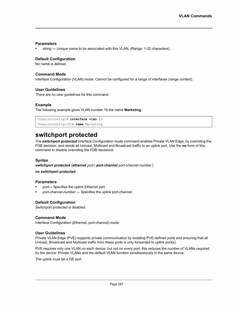
VLAN Commands
Parameters• string — Unique name to be associated with this VLAN. (Range: 1-32 characters)
Default ConfigurationNo name is defined.
Command ModeInterface Configuration (VLAN) mode. Cannot be configured for a range of interfaces (range context).
User GuidelinesThere are no user guidelines for this command.
ExampleThe following example gives VLAN number 19 the name Marketing.
switchport protectedThe switchport protected Interface Configuration mode command enables Private VLAN Edge, by overriding the FDB decision, and sends all Unicast, Multicast and Broadcast traffic to an uplink port. Use the no form of this command to disable overriding the FDB decisiond.
Syntaxswitchport protected {ethernet port | port-channel port-channel-number }
no switchport protected
Parameters• port— Specifies the uplink Ethernet port.• port-channel-number — Specifies the uplink port-channel.
Default ConfigurationSwitchport protected is disabled.
Command ModeInterface Configuration (Ethernet, port-channel) mode
User GuidelinesPrivate VLAN Edge (PVE) supports private communication by isolating PVE-defined ports and ensuring that all Unicast, Broadcast and Multicast traffic from these ports is only forwarded to uplink port(s).
PVE requires only one VLAN on each device, but not on every port; this reduces the number of VLANs required by the device. Private VLANs and the default VLAN function simultaneously in the same device.
The uplink must be a GE port.
Console(config)# interface vlan 19Console(config-if)# name Marketing
Page 287
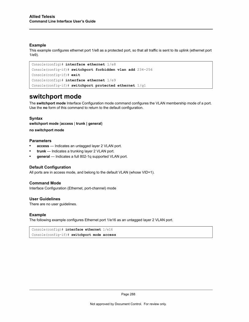
Allied Telesis Command Line Interface User’s Guide
ExampleThis example configures ethernet port 1/e8 as a protected port, so that all traffic is sent to its uplink (ethernet port 1/e9).
switchport modeThe switchport mode Interface Configuration mode command configures the VLAN membership mode of a port. Use the no form of this command to return to the default configuration.
Syntaxswitchport mode {access | trunk | general}
no switchport mode
Parameters• access — Indicates an untagged layer 2 VLAN port.• trunk — Indicates a trunking layer 2 VLAN port.• general — Indicates a full 802-1q supported VLAN port.
Default ConfigurationAll ports are in access mode, and belong to the default VLAN (whose VID=1).
Command ModeInterface Configuration (Ethernet, port-channel) mode
User GuidelinesThere are no user guidelines.
ExampleThe following example configures Ethernet port 1/e16 as an untagged layer 2 VLAN port.
Console(config)# interface ethernet 1/e8Console(config-if)# switchport forbidden vlan add 234-256Console(config-if)# exitConsole(config)# interface ethernet 1/e9Console(config-if)# switchport protected ethernet 1/g1
Console(config)# interface ethernet 1/e16Console(config-if)# switchport mode access
Page 288
Not approved by Document Control. For review only.
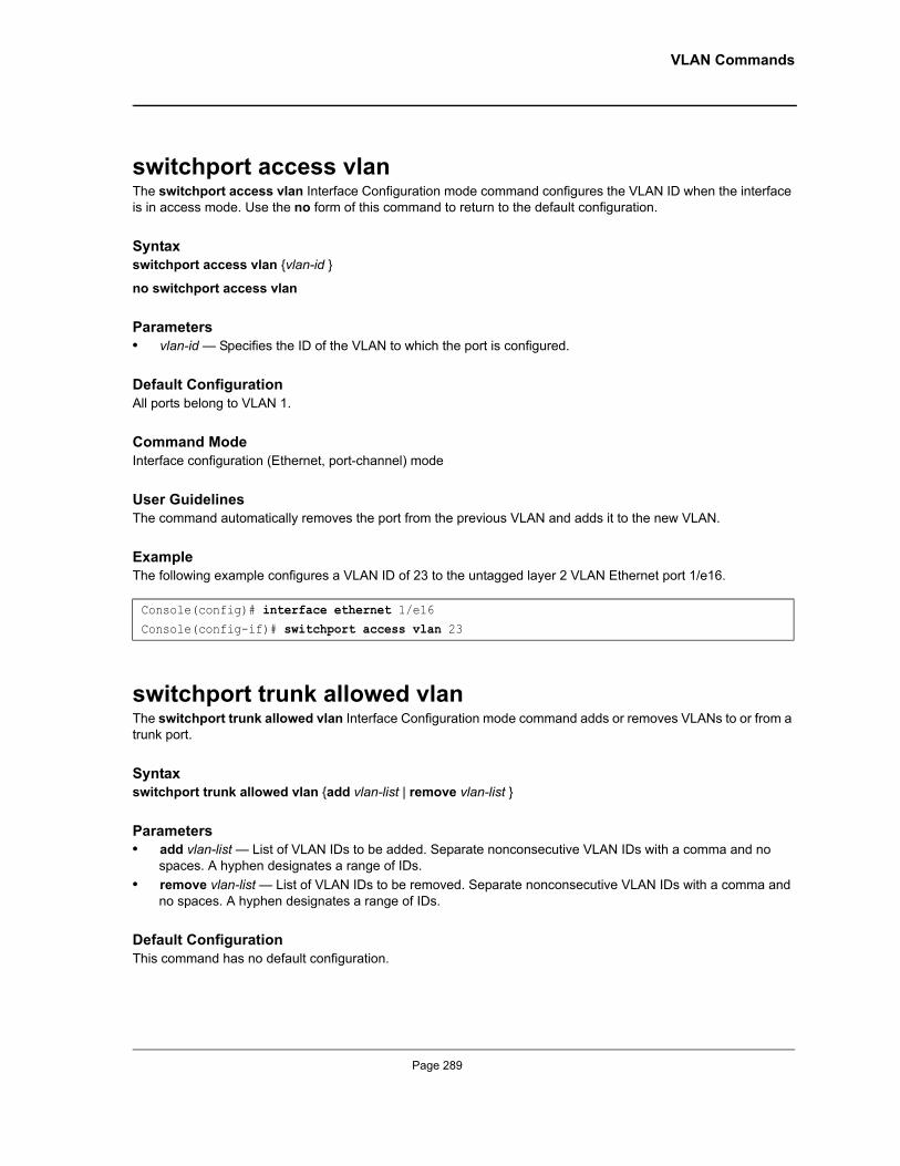
VLAN Commands
switchport access vlanThe switchport access vlan Interface Configuration mode command configures the VLAN ID when the interface is in access mode. Use the no form of this command to return to the default configuration.
Syntaxswitchport access vlan {vlan-id }
no switchport access vlan
Parameters• vlan-id — Specifies the ID of the VLAN to which the port is configured.
Default ConfigurationAll ports belong to VLAN 1.
Command ModeInterface configuration (Ethernet, port-channel) mode
User GuidelinesThe command automatically removes the port from the previous VLAN and adds it to the new VLAN.
ExampleThe following example configures a VLAN ID of 23 to the untagged layer 2 VLAN Ethernet port 1/e16.
switchport trunk allowed vlanThe switchport trunk allowed vlan Interface Configuration mode command adds or removes VLANs to or from a trunk port.
Syntaxswitchport trunk allowed vlan {add vlan-list | remove vlan-list }
Parameters• add vlan-list — List of VLAN IDs to be added. Separate nonconsecutive VLAN IDs with a comma and no
spaces. A hyphen designates a range of IDs.• remove vlan-list — List of VLAN IDs to be removed. Separate nonconsecutive VLAN IDs with a comma and
no spaces. A hyphen designates a range of IDs.
Default ConfigurationThis command has no default configuration.
Console(config)# interface ethernet 1/e16Console(config-if)# switchport access vlan 23
Page 289
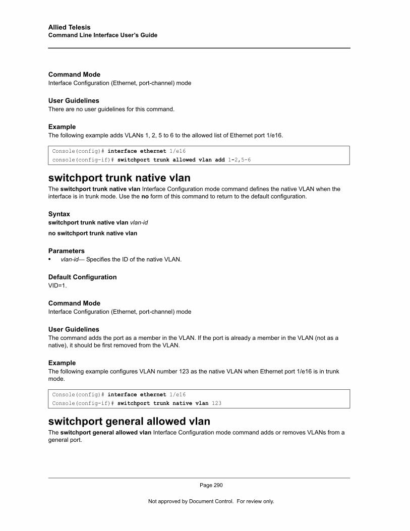
Allied Telesis Command Line Interface User’s Guide
Command ModeInterface Configuration (Ethernet, port-channel) mode
User GuidelinesThere are no user guidelines for this command.
ExampleThe following example adds VLANs 1, 2, 5 to 6 to the allowed list of Ethernet port 1/e16.
switchport trunk native vlanThe switchport trunk native vlan Interface Configuration mode command defines the native VLAN when the interface is in trunk mode. Use the no form of this command to return to the default configuration.
Syntaxswitchport trunk native vlan vlan-id
no switchport trunk native vlan
Parameters• vlan-id— Specifies the ID of the native VLAN.
Default ConfigurationVID=1.
Command ModeInterface Configuration (Ethernet, port-channel) mode
User GuidelinesThe command adds the port as a member in the VLAN. If the port is already a member in the VLAN (not as a native), it should be first removed from the VLAN.
ExampleThe following example configures VLAN number 123 as the native VLAN when Ethernet port 1/e16 is in trunk mode.
switchport general allowed vlanThe switchport general allowed vlan Interface Configuration mode command adds or removes VLANs from a general port.
Console(config)# interface ethernet 1/e16console(config-if)# switchport trunk allowed vlan add 1-2,5-6
Console(config)# interface ethernet 1/e16Console(config-if)# switchport trunk native vlan 123
Page 290
Not approved by Document Control. For review only.
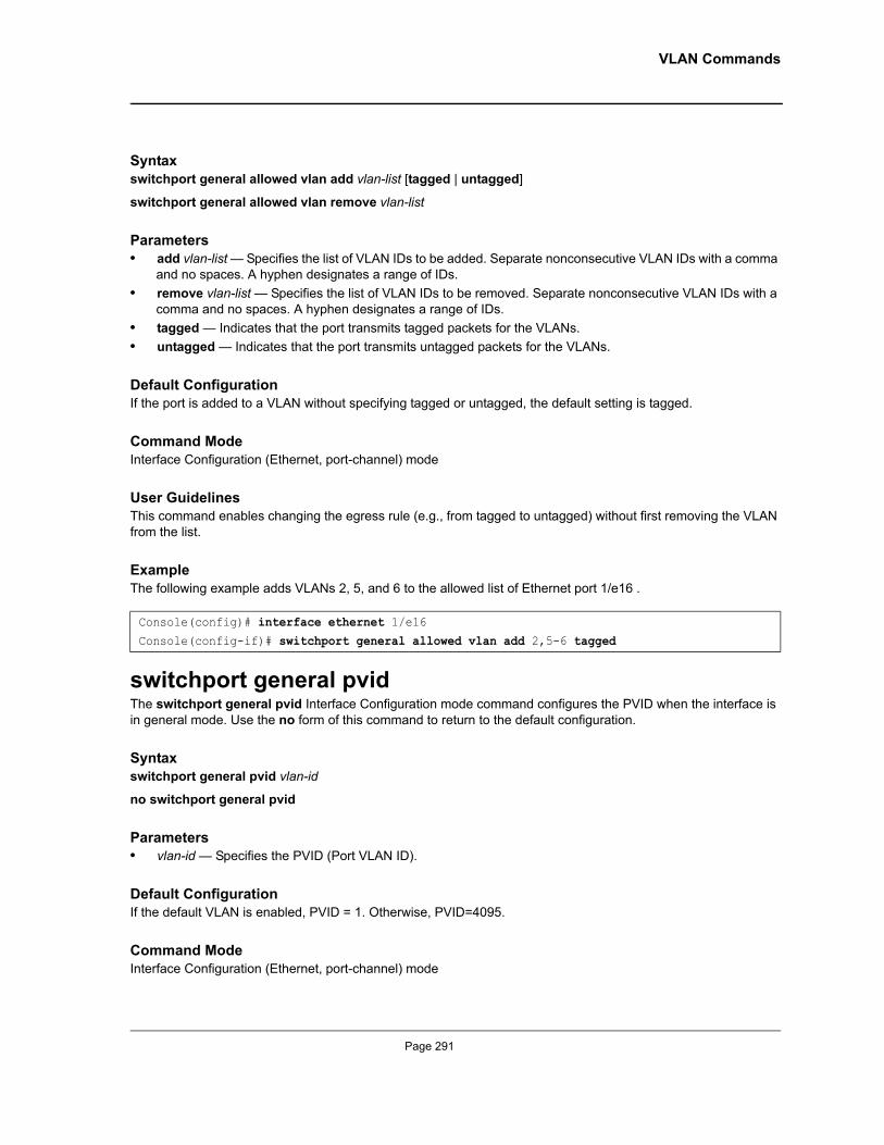
VLAN Commands
Syntaxswitchport general allowed vlan add vlan-list [tagged | untagged]
switchport general allowed vlan remove vlan-list
Parameters• add vlan-list — Specifies the list of VLAN IDs to be added. Separate nonconsecutive VLAN IDs with a comma
and no spaces. A hyphen designates a range of IDs.• remove vlan-list — Specifies the list of VLAN IDs to be removed. Separate nonconsecutive VLAN IDs with a
comma and no spaces. A hyphen designates a range of IDs.• tagged — Indicates that the port transmits tagged packets for the VLANs.• untagged — Indicates that the port transmits untagged packets for the VLANs.
Default ConfigurationIf the port is added to a VLAN without specifying tagged or untagged, the default setting is tagged.
Command ModeInterface Configuration (Ethernet, port-channel) mode
User GuidelinesThis command enables changing the egress rule (e.g., from tagged to untagged) without first removing the VLAN from the list.
ExampleThe following example adds VLANs 2, 5, and 6 to the allowed list of Ethernet port 1/e16 .
switchport general pvidThe switchport general pvid Interface Configuration mode command configures the PVID when the interface is in general mode. Use the no form of this command to return to the default configuration.
Syntaxswitchport general pvid vlan-id
no switchport general pvid
Parameters• vlan-id — Specifies the PVID (Port VLAN ID).
Default ConfigurationIf the default VLAN is enabled, PVID = 1. Otherwise, PVID=4095.
Command ModeInterface Configuration (Ethernet, port-channel) mode
Console(config)# interface ethernet 1/e16Console(config-if)# switchport general allowed vlan add 2,5-6 tagged
Page 291
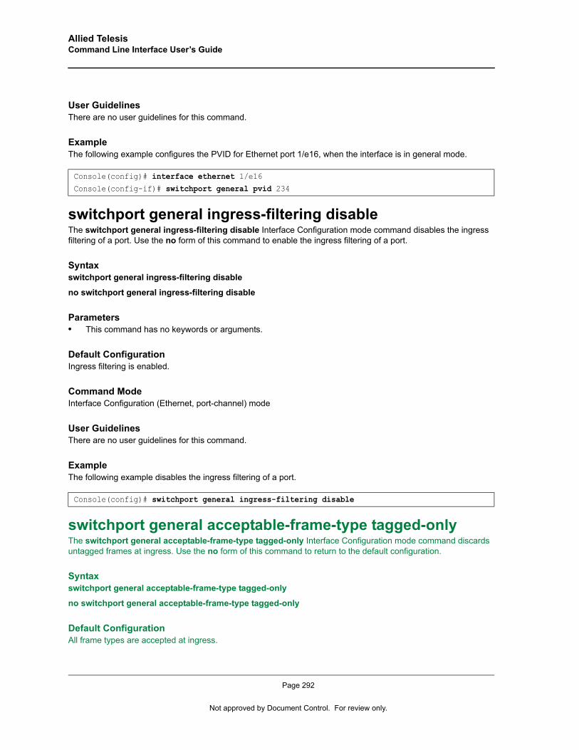
Allied Telesis Command Line Interface User’s Guide
User GuidelinesThere are no user guidelines for this command.
ExampleThe following example configures the PVID for Ethernet port 1/e16, when the interface is in general mode.
switchport general ingress-filtering disableThe switchport general ingress-filtering disable Interface Configuration mode command disables the ingress filtering of a port. Use the no form of this command to enable the ingress filtering of a port.
Syntaxswitchport general ingress-filtering disable
no switchport general ingress-filtering disable
Parameters• This command has no keywords or arguments.
Default ConfigurationIngress filtering is enabled.
Command ModeInterface Configuration (Ethernet, port-channel) mode
User GuidelinesThere are no user guidelines for this command.
ExampleThe following example disables the ingress filtering of a port.
switchport general acceptable-frame-type tagged-onlyThe switchport general acceptable-frame-type tagged-only Interface Configuration mode command discards untagged frames at ingress. Use the no form of this command to return to the default configuration.
Syntaxswitchport general acceptable-frame-type tagged-only
no switchport general acceptable-frame-type tagged-only
Default ConfigurationAll frame types are accepted at ingress.
Console(config)# interface ethernet 1/e16Console(config-if)# switchport general pvid 234
Console(config)# switchport general ingress-filtering disable
Page 292
Not approved by Document Control. For review only.
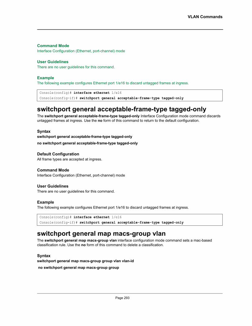
VLAN Commands
Command ModeInterface Configuration (Ethernet, port-channel) mode
User GuidelinesThere are no user guidelines for this command.
ExampleThe following example configures Ethernet port 1/e16 to discard untagged frames at ingress.
switchport general acceptable-frame-type tagged-onlyThe switchport general acceptable-frame-type tagged-only Interface Configuration mode command discards untagged frames at ingress. Use the no form of this command to return to the default configuration.
Syntaxswitchport general acceptable-frame-type tagged-only
no switchport general acceptable-frame-type tagged-only
Default ConfigurationAll frame types are accepted at ingress.
Command ModeInterface Configuration (Ethernet, port-channel) mode
User GuidelinesThere are no user guidelines for this command.
ExampleThe following example configures Ethernet port 1/e16 to discard untagged frames at ingress.
switchport general map macs-group vlanThe switchport general map macs-group vlan interface configuration mode command sets a mac-based classification rule. Use the no form of this command to delete a classification.
Syntaxswitchport general map macs-group group vlan vlan-id
no switchport general map macs-group group
Console(config)# interface ethernet 1/e16Console(config-if)# switchport general acceptable-frame-type tagged-only
Console(config)# interface ethernet 1/e16Console(config-if)# switchport general acceptable-frame-type tagged-only
Page 293
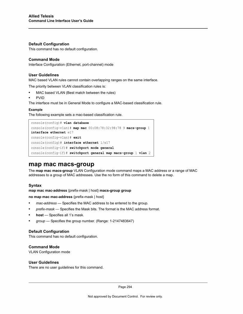
Allied Telesis Command Line Interface User’s Guide
Default ConfigurationThis command has no default configuration.
Command ModeInterface Configuration (Ethernet, port-channel) mode
User GuidelinesMAC based VLAN rules cannot contain overlapping ranges on the same interface.
The priority between VLAN classification rules is:
• MAC based VLAN (Best match between the rules)• PVIDThe interface must be in General Mode to configure a MAC-based classification rule.
ExampleThe following example sets a mac-based classification rule.
map mac macs-groupThe map mac macs-group VLAN Configuration mode command maps a MAC address or a range of MAC addresses to a group of MAC addresses. Use the no form of this command to delete a map.
Syntaxmap mac mac-address {prefix-mask | host} macs-group group
no map mac mac-address {prefix-mask | host}
• mac-address — Specifies the MAC address to be entered to the group.
• prefix-mask — Specifies the Mask bits. The format is the MAC address format.
• host — Specifies all 1’s mask.
• group — Specifies the group number. (Range: 1-2147483647)
Default ConfigurationThis command has no default configuration.
Command ModeVLAN Configuration mode
User GuidelinesThere are no user guidelines for this command.
console(config)# vlan databaseconsole(config-vlan)# map mac 00:08:78:32:98:78 9 macs-group 1 interface ethernet e17console(config-vlan)# exitconsole(config)# interface ethernet 1/e17console(config-if)# switchport mode generalconsole(config-if)# switchport general map macs-group 1 vlan 2
Page 294
Not approved by Document Control. For review only.
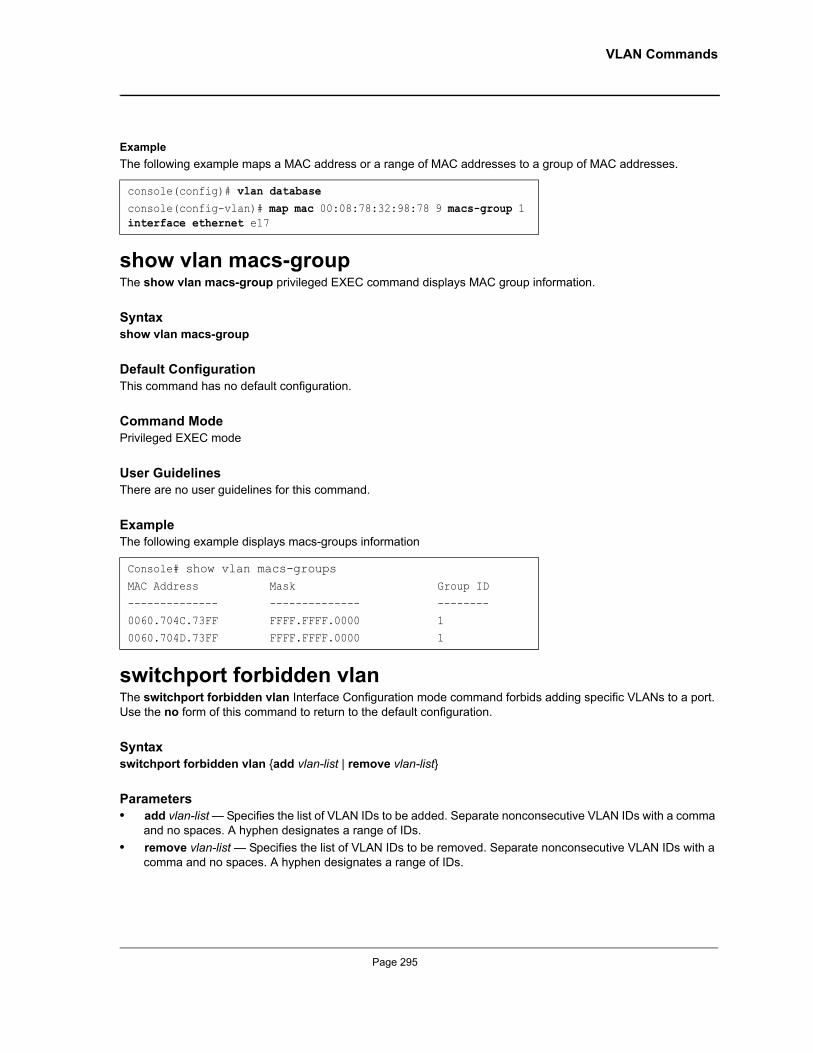
VLAN Commands
ExampleThe following example maps a MAC address or a range of MAC addresses to a group of MAC addresses.
show vlan macs-groupThe show vlan macs-group privileged EXEC command displays MAC group information.
Syntaxshow vlan macs-group
Default ConfigurationThis command has no default configuration.
Command ModePrivileged EXEC mode
User GuidelinesThere are no user guidelines for this command.
ExampleThe following example displays macs-groups information
switchport forbidden vlanThe switchport forbidden vlan Interface Configuration mode command forbids adding specific VLANs to a port. Use the no form of this command to return to the default configuration.
Syntaxswitchport forbidden vlan {add vlan-list | remove vlan-list}
Parameters• add vlan-list — Specifies the list of VLAN IDs to be added. Separate nonconsecutive VLAN IDs with a comma
and no spaces. A hyphen designates a range of IDs.• remove vlan-list — Specifies the list of VLAN IDs to be removed. Separate nonconsecutive VLAN IDs with a
comma and no spaces. A hyphen designates a range of IDs.
console(config)# vlan databaseconsole(config-vlan)# map mac 00:08:78:32:98:78 9 macs-group 1 interface ethernet e17
Console# show vlan macs-groupsMAC Address Mask Group ID
-------------- -------------- --------0060.704C.73FF FFFF.FFFF.0000 1
0060.704D.73FF FFFF.FFFF.0000 1
Page 295
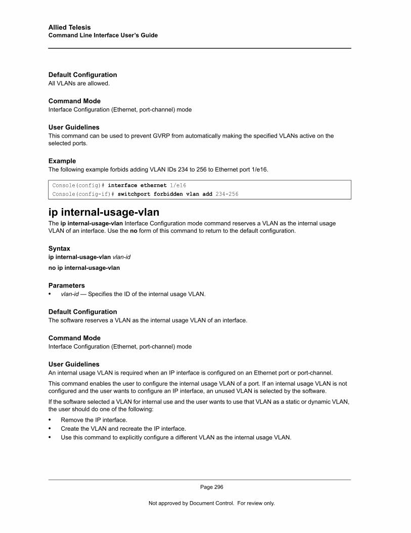
Allied Telesis Command Line Interface User’s Guide
Default ConfigurationAll VLANs are allowed.
Command ModeInterface Configuration (Ethernet, port-channel) mode
User GuidelinesThis command can be used to prevent GVRP from automatically making the specified VLANs active on the selected ports.
ExampleThe following example forbids adding VLAN IDs 234 to 256 to Ethernet port 1/e16.
ip internal-usage-vlanThe ip internal-usage-vlan Interface Configuration mode command reserves a VLAN as the internal usage VLAN of an interface. Use the no form of this command to return to the default configuration.
Syntaxip internal-usage-vlan vlan-id
no ip internal-usage-vlan
Parameters• vlan-id — Specifies the ID of the internal usage VLAN.
Default ConfigurationThe software reserves a VLAN as the internal usage VLAN of an interface.
Command Mode Interface Configuration (Ethernet, port-channel) mode
User GuidelinesAn internal usage VLAN is required when an IP interface is configured on an Ethernet port or port-channel.
This command enables the user to configure the internal usage VLAN of a port. If an internal usage VLAN is not configured and the user wants to configure an IP interface, an unused VLAN is selected by the software.
If the software selected a VLAN for internal use and the user wants to use that VLAN as a static or dynamic VLAN, the user should do one of the following:
• Remove the IP interface.• Create the VLAN and recreate the IP interface.• Use this command to explicitly configure a different VLAN as the internal usage VLAN.
Console(config)# interface ethernet 1/e16Console(config-if)# switchport forbidden vlan add 234-256
Page 296
Not approved by Document Control. For review only.

VLAN Commands
ExampleThe following example reserves an unused VLAN as the internal usage VLAN of ethernet port 1/e8.
Console# configConsole(config)# interface ethernet 1/e8Console(config-if)# ip internal-usage-vlan
Page 297
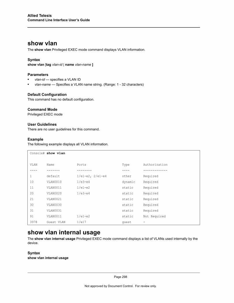
Allied Telesis Command Line Interface User’s Guide
show vlanThe show vlan Privileged EXEC mode command displays VLAN information.
Syntaxshow vlan [tag vlan-id | name vlan-name ]
Parameters• vlan-id — specifies a VLAN ID• vlan-name — Specifies a VLAN name string. (Range: 1 - 32 characters)
Default ConfigurationThis command has no default configuration.
Command ModePrivileged EXEC mode
User GuidelinesThere are no user guidelines for this command.
ExampleThe following example displays all VLAN information.
show vlan internal usageThe show vlan internal usage Privileged EXEC mode command displays a list of VLANs used internally by the device.
Syntaxshow vlan internal usage
Console# show vlan
VLAN Name Ports Type Authorization
---- ------- -------- ---- -------------
1 default 1/e1-e2, 2/e1-e4 other Required
10 VLAN0010 1/e3-e4 dynamic Required
11 VLAN0011 1/e1-e2 static Required
20 VLAN0020 1/e3-e4 static Required
21 VLAN0021 static Required
30 VLAN0030 static Required
31 VLAN0031 static Required
91 VLAN0011 1/e1-e2 static Not Required
3978 Guest VLAN 1/e17 guest -
Page 298
Not approved by Document Control. For review only.
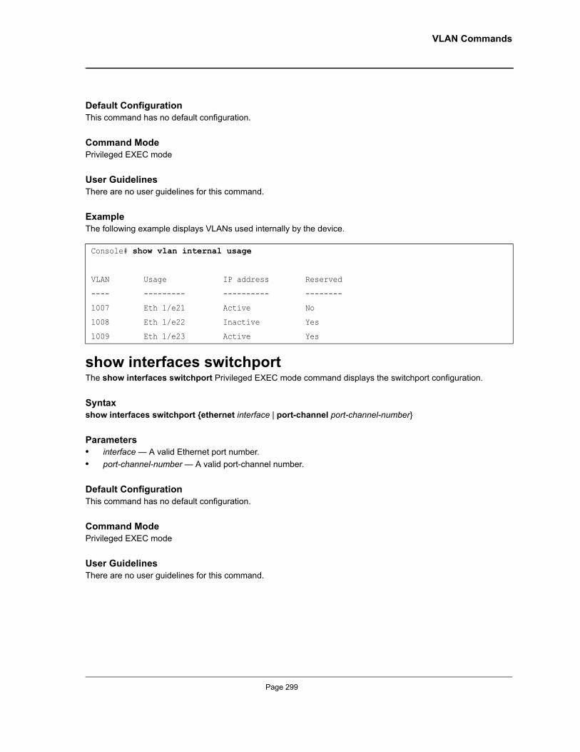
VLAN Commands
Default ConfigurationThis command has no default configuration.
Command ModePrivileged EXEC mode
User GuidelinesThere are no user guidelines for this command.
ExampleThe following example displays VLANs used internally by the device.
show interfaces switchportThe show interfaces switchport Privileged EXEC mode command displays the switchport configuration.
Syntaxshow interfaces switchport {ethernet interface | port-channel port-channel-number}
Parameters• interface — A valid Ethernet port number.• port-channel-number — A valid port-channel number.
Default ConfigurationThis command has no default configuration.
Command ModePrivileged EXEC mode
User GuidelinesThere are no user guidelines for this command.
Console# show vlan internal usage
VLAN Usage IP address Reserved
---- --------- ---------- --------
1007 Eth 1/e21 Active No
1008 Eth 1/e22 Inactive Yes
1009 Eth 1/e23 Active Yes
Page 299
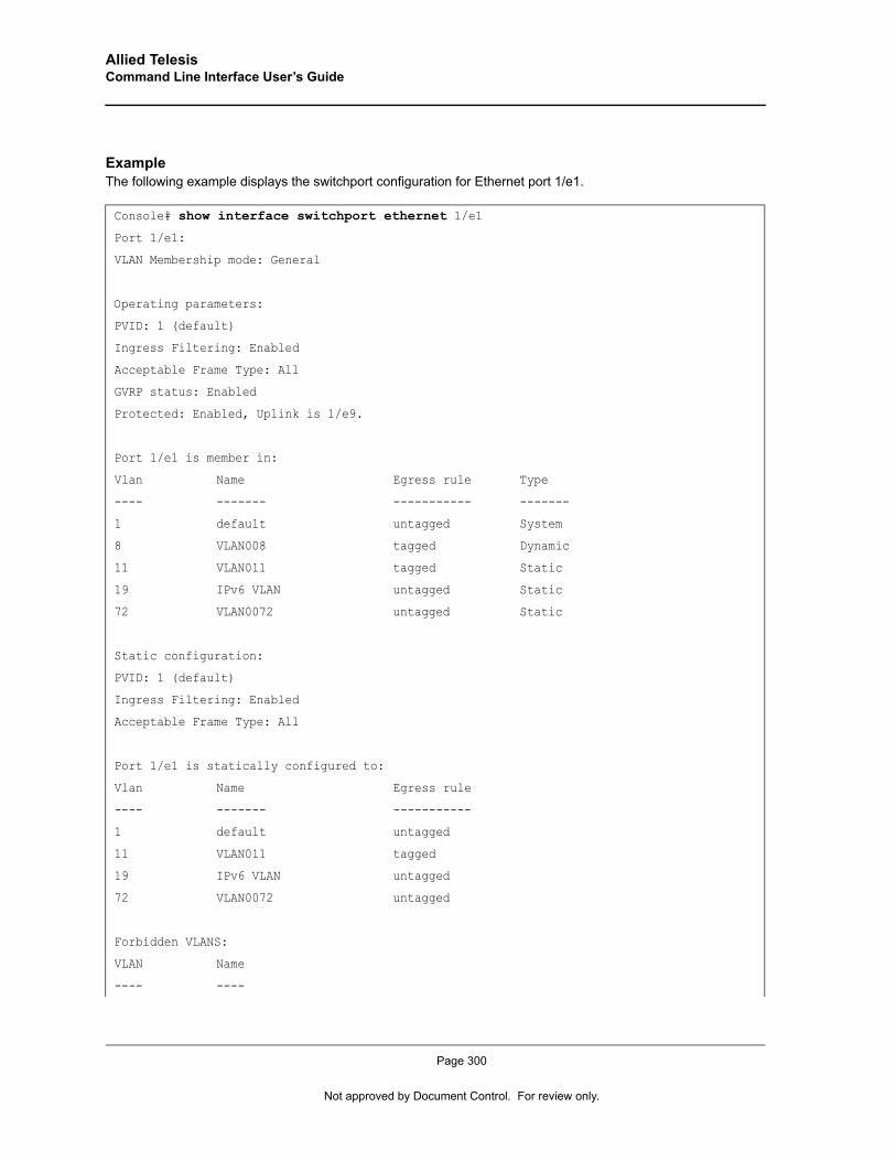
Allied Telesis Command Line Interface User’s Guide
ExampleThe following example displays the switchport configuration for Ethernet port 1/e1.
Console# show interface switchport ethernet 1/e1
Port 1/e1:
VLAN Membership mode: General
Operating parameters:
PVID: 1 (default)
Ingress Filtering: Enabled
Acceptable Frame Type: All
GVRP status: Enabled
Protected: Enabled, Uplink is 1/e9.
Port 1/e1 is member in:
Vlan Name Egress rule Type
---- ------- ----------- -------
1 default untagged System
8 VLAN008 tagged Dynamic
11 VLAN011 tagged Static
19 IPv6 VLAN untagged Static
72 VLAN0072 untagged Static
Static configuration:
PVID: 1 (default)
Ingress Filtering: Enabled
Acceptable Frame Type: All
Port 1/e1 is statically configured to:
Vlan Name Egress rule
---- ------- -----------
1 default untagged
11 VLAN011 tagged
19 IPv6 VLAN untagged
72 VLAN0072 untagged
Forbidden VLANS:
VLAN Name
---- ----
Page 300
Not approved by Document Control. For review only.
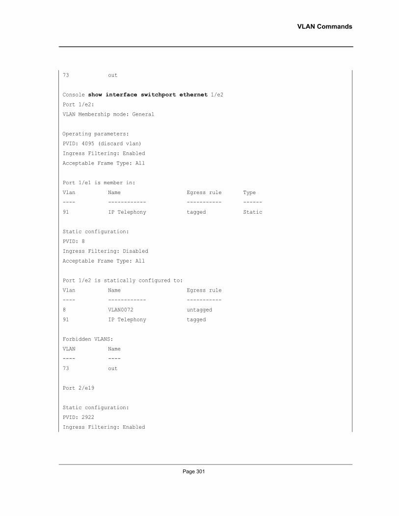
VLAN Commands
73 out
Console show interface switchport ethernet 1/e2
Port 1/e2:
VLAN Membership mode: General
Operating parameters:
PVID: 4095 (discard vlan)
Ingress Filtering: Enabled
Acceptable Frame Type: All
Port 1/e1 is member in:
Vlan Name Egress rule Type
---- ------------ ----------- ------
91 IP Telephony tagged Static
Static configuration:
PVID: 8
Ingress Filtering: Disabled
Acceptable Frame Type: All
Port 1/e2 is statically configured to:
Vlan Name Egress rule
---- ------------ -----------
8 VLAN0072 untagged
91 IP Telephony tagged
Forbidden VLANS:
VLAN Name
---- ----
73 out
Port 2/e19
Static configuration:
PVID: 2922
Ingress Filtering: Enabled
Page 301

Allied Telesis Command Line Interface User’s Guide
Acceptable Frame Type: Untagged
GVRP status: Disabled
Page 302
Not approved by Document Control. For review only.

Web Server Commands
Chapter 31.Web Server Commands
ip http serverThe ip http server Global Configuration mode command enables configuring the device from a browser. Use the no form of this command to disable this function.
Syntaxip http server
no ip http server
Default ConfigurationHTTP server is enabled.
Command ModeGlobal Configuration mode
User GuidelinesOnly a user with access level 15 can use the Web server.
ExampleThe following example enables configuring the device from a browser.
ip http portThe ip http port Global Configuration mode command specifies the TCP port to be used by the Web browser interface. Use the no form of this command to return to the default configuration.
Syntaxip http port port-number
no ip http port
Parameters• port-number — Port number for use by the HTTP server. (Range: 0 - 65535)
Default ConfigurationThe default port number is 80.
Command ModeGlobal Configuration mode
Console(config)# ip http server
Page 303
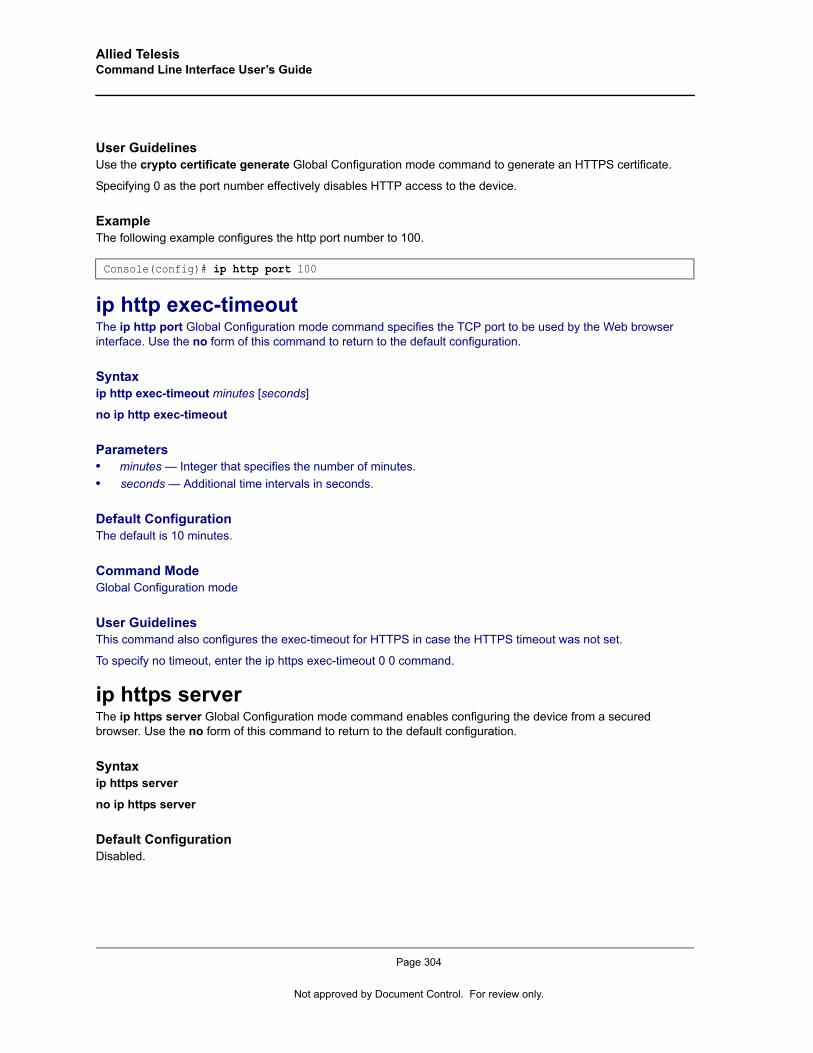
Allied Telesis Command Line Interface User’s Guide
User GuidelinesUse the crypto certificate generate Global Configuration mode command to generate an HTTPS certificate.
Specifying 0 as the port number effectively disables HTTP access to the device.
ExampleThe following example configures the http port number to 100.
ip http exec-timeoutThe ip http port Global Configuration mode command specifies the TCP port to be used by the Web browser interface. Use the no form of this command to return to the default configuration.
Syntaxip http exec-timeout minutes [seconds]
no ip http exec-timeout
Parameters• minutes — Integer that specifies the number of minutes.• seconds — Additional time intervals in seconds.
Default ConfigurationThe default is 10 minutes.
Command ModeGlobal Configuration mode
User GuidelinesThis command also configures the exec-timeout for HTTPS in case the HTTPS timeout was not set.
To specify no timeout, enter the ip https exec-timeout 0 0 command.
ip https serverThe ip https server Global Configuration mode command enables configuring the device from a secured browser. Use the no form of this command to return to the default configuration.
Syntaxip https server
no ip https server
Default ConfigurationDisabled.
Console(config)# ip http port 100
Page 304
Not approved by Document Control. For review only.
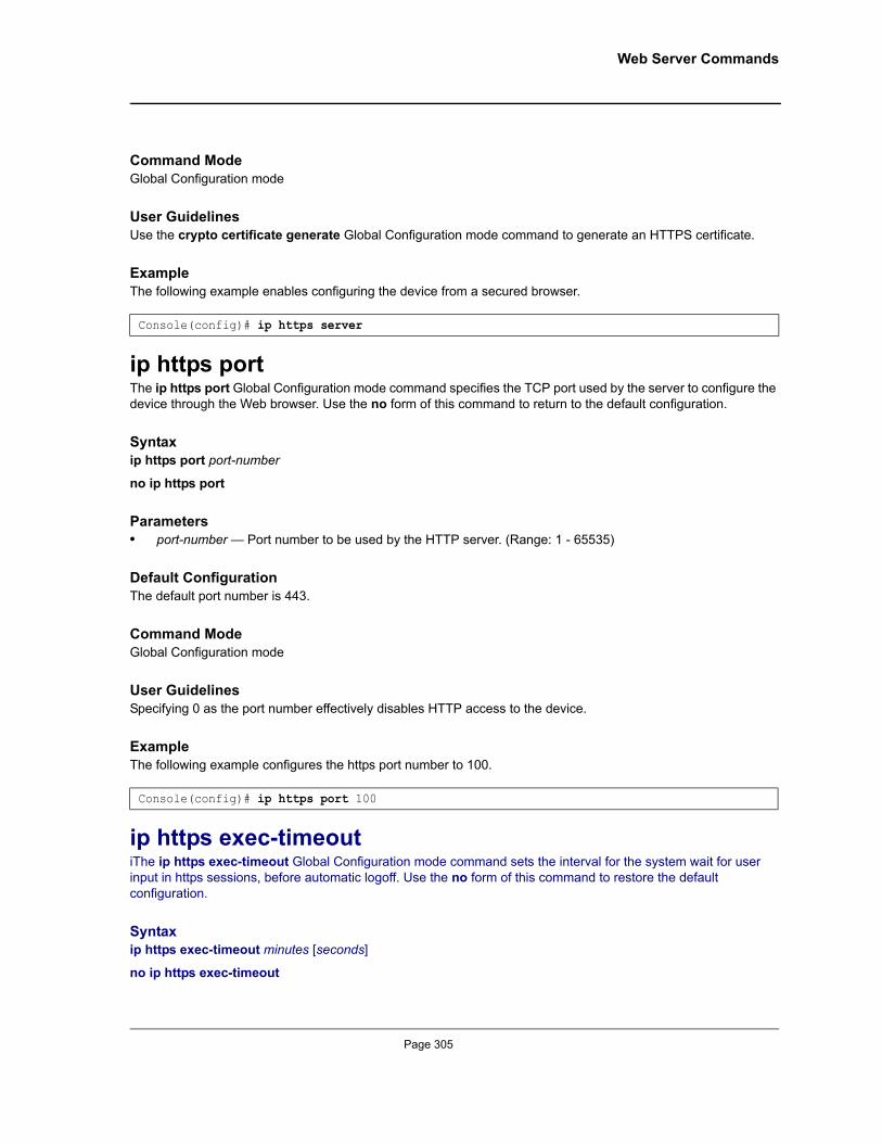
Web Server Commands
Command ModeGlobal Configuration mode
User GuidelinesUse the crypto certificate generate Global Configuration mode command to generate an HTTPS certificate.
ExampleThe following example enables configuring the device from a secured browser.
ip https portThe ip https port Global Configuration mode command specifies the TCP port used by the server to configure the device through the Web browser. Use the no form of this command to return to the default configuration.
Syntaxip https port port-number
no ip https port
Parameters• port-number — Port number to be used by the HTTP server. (Range: 1 - 65535)
Default ConfigurationThe default port number is 443.
Command ModeGlobal Configuration mode
User GuidelinesSpecifying 0 as the port number effectively disables HTTP access to the device.
ExampleThe following example configures the https port number to 100.
ip https exec-timeoutiThe ip https exec-timeout Global Configuration mode command sets the interval for the system wait for user input in https sessions, before automatic logoff. Use the no form of this command to restore the default configuration.
Syntaxip https exec-timeout minutes [seconds]
no ip https exec-timeout
Console(config)# ip https server
Console(config)# ip https port 100
Page 305

Allied Telesis Command Line Interface User’s Guide
Parameters• minutes — Integer that specifies the number of minutes. (Range: 1 - 65535)• seconds — Additional time intervals in seconds. (Range: 0-59)
Default ConfigurationThe default configuration is the exec-timeout set by the ip http exec-timeout command.
Command ModeGlobal Configuration mode
User GuidelinesTo specify no timeout, enter the ip https exec-timeout 0 0 command.
ExampleThe following example configures sets the interval for the system to 1hour.
crypto certificate generateThe crypto certificate generate Global Configuration mode command generates a self-signed HTTPS certificate.
Syntaxcrypto certificate [number] generate [key-generate length][cn common- name][ou organization-unit][or organization] [loc location] [st state] [cu country] [duration days]
Parameters• number — Specifies the certificate number. (Range: 1 - 2)• key-generate — Regenerate the SSL RSA key.• length — Specifies the SSL RSA key length. (Range: 512 - 2048)• common- name — Specifies the fully qualified URL or IP address of the device.
(Range: 1 - 64)• organization — Specifies the organization name. (Range: 1 - 64)• organization-unit — Specifies the organization-unit or department name.(Range: 1 - 64)• location — Specifies the location or city name. (Range: 1 - 64)• state — Specifies the state or province name. (Range: 1 - 64)• country — Specifies the country name. (Range: 2 - 2)• days — Specifies number of days certification is valid. (Range: 30 - 3650)
Default ConfigurationThe Certificate and SSL’s RSA key pairs do not exist.
If no certificate number is specified, the default certificate number is 1.
If no RSA key length is specified, the default length is 1024.
Console(config)# ip https exec-timeout 60
Page 306
Not approved by Document Control. For review only.

Web Server Commands
If no URL or IP address is specified, the default common name is the lowest IP address of the device at the time that the certificate is generated.
If the number of days is not specified, the default period of time that the certification is valid is 365 days.
Command ModeGlobal Configuration mode
User GuidelinesThe command is not saved in the device configuration; however, the certificate and keys generated by this command are saved in the private configuration (which is never displayed to the user or backed up to another device).
Use this command to generate a self-signed certificate for the device.
If the RSA keys do not exist, parameter key-generate must be used.
ExampleThe following example regenerates an HTTPS certificate.
crypto certificate requestThe crypto certificate request Privileged EXEC mode command generates and displays certificate requests for HTTPS.
Syntaxcrypto certificate number request [cn common- name ][ou organization-unit][or organization] [loc location] [st state] [cu country]
Parameters• number — Specifies the certificate number. (Range: 1 - 2)• common- name — Specifies the fully qualified URL or IP address of the device.
(Range: 1- 64)• organization-unit — Specifies the organization-unit or department name. (Range: 1- 64)• organization — Specifies the organization name. (Range: 1- 64)• location — Specifies the location or city name. (Range: 1- 64)• state — Specifies the state or province name. (Range: 1- 64)• country — Specifies the country name. (Range: 1- 2)
Default ConfigurationThere is no default configuration for this command.
Command ModePrivileged EXEC mode
Console(config)# crypto certificate 1 generate key-generate
Page 307
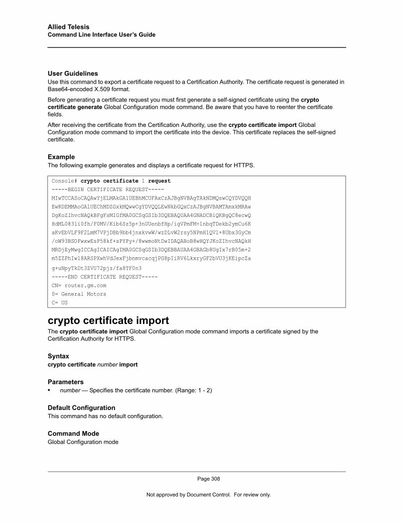
Allied Telesis Command Line Interface User’s Guide
User GuidelinesUse this command to export a certificate request to a Certification Authority. The certificate request is generated in Base64-encoded X.509 format.
Before generating a certificate request you must first generate a self-signed certificate using the crypto certificate generate Global Configuration mode command. Be aware that you have to reenter the certificate fields.
After receiving the certificate from the Certification Authority, use the crypto certificate import Global Configuration mode command to import the certificate into the device. This certificate replaces the self-signed certificate.
ExampleThe following example generates and displays a certificate request for HTTPS.
crypto certificate importThe crypto certificate import Global Configuration mode command imports a certificate signed by the Certification Authority for HTTPS.
Syntaxcrypto certificate number import
Parameters• number — Specifies the certificate number. (Range: 1 - 2)
Default ConfigurationThis command has no default configuration.
Command ModeGlobal Configuration mode
Console# crypto certificate 1 request-----BEGIN CERTIFICATE REQUEST-----
MIwTCCASoCAQAwYjELMAkGA1UEBhMCUFAxCzAJBgNVBAgTAkNDMQswCQYDVQQHEwRDEMMAoGA1UEChMDZGxkMQwwCgYDVQQLEwNkbGQxCzAJBgNVBAMTAmxkMRAw
DgKoZIhvcNAQkBFgFsMIGfMA0GCSqGSIb3DQEBAQUAA4GNADCBiQKBgQC8ecwQ
HdML0831i0fh/F0MV/Kib6Sz5p+3nUUenbfHp/igVPmFM+1nbqTDekb2ymCu6KaKvEbVLF9F2LmM7VPjDBb9bb4jnxkvwW/wzDLvW2rsy5NPmH1QVl+8Ubx3GyCm
/oW93BSOFwxwEsP58kf+sPYPy+/8wwmoNtDwIDAQABoB8wHQYJKoZIhvcNAQkH
MRDjEyMwgICCAgICAICAgIMA0GCSqGSIb3DQEBBAUAA4GBAGb8UgIx7rB05m+2m5ZZPhIwl8ARSPXwhVdJexFjbnmvcacqjPG8pIiRV6LkxryGF2bVU3jKEipcZa
g+uNpyTkDt3ZVU72pjz/fa8TF0n3
-----END CERTIFICATE REQUEST-----
CN= router.gm.com0= General Motors
C= US
Page 308
Not approved by Document Control. For review only.
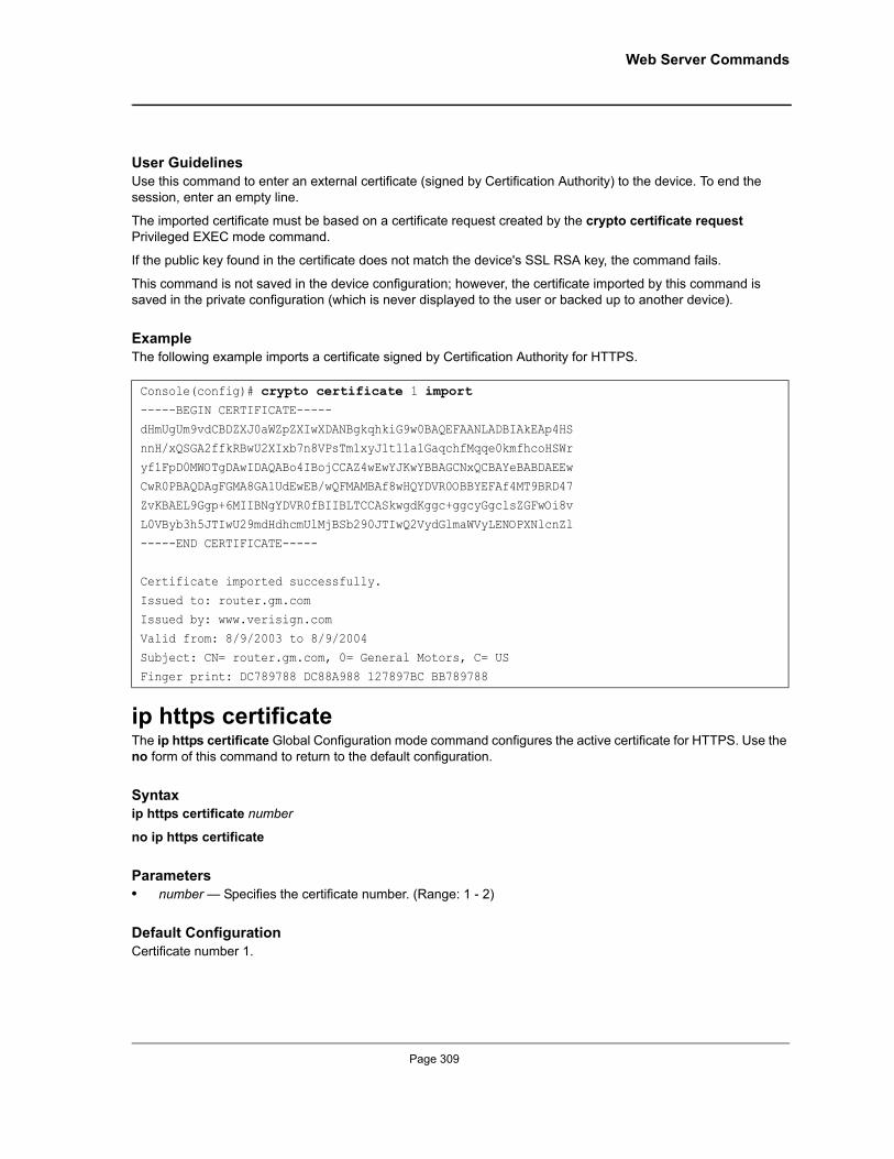
Web Server Commands
User GuidelinesUse this command to enter an external certificate (signed by Certification Authority) to the device. To end the session, enter an empty line.
The imported certificate must be based on a certificate request created by the crypto certificate request Privileged EXEC mode command.
If the public key found in the certificate does not match the device's SSL RSA key, the command fails.
This command is not saved in the device configuration; however, the certificate imported by this command is saved in the private configuration (which is never displayed to the user or backed up to another device).
ExampleThe following example imports a certificate signed by Certification Authority for HTTPS.
ip https certificate The ip https certificate Global Configuration mode command configures the active certificate for HTTPS. Use the no form of this command to return to the default configuration.
Syntaxip https certificate number
no ip https certificate
Parameters• number — Specifies the certificate number. (Range: 1 - 2)
Default ConfigurationCertificate number 1.
Console(config)# crypto certificate 1 import-----BEGIN CERTIFICATE-----
dHmUgUm9vdCBDZXJ0aWZpZXIwXDANBgkqhkiG9w0BAQEFAANLADBIAkEAp4HSnnH/xQSGA2ffkRBwU2XIxb7n8VPsTm1xyJ1t11a1GaqchfMqqe0kmfhcoHSWr
yf1FpD0MWOTgDAwIDAQABo4IBojCCAZ4wEwYJKwYBBAGCNxQCBAYeBABDAEEw
CwR0PBAQDAgFGMA8GA1UdEwEB/wQFMAMBAf8wHQYDVR0OBBYEFAf4MT9BRD47ZvKBAEL9Ggp+6MIIBNgYDVR0fBIIBLTCCASkwgdKggc+ggcyGgclsZGFwOi8v
L0VByb3h5JTIwU29mdHdhcmUlMjBSb290JTIwQ2VydGlmaWVyLENOPXNlcnZl
-----END CERTIFICATE-----
Certificate imported successfully.
Issued to: router.gm.comIssued by: www.verisign.com
Valid from: 8/9/2003 to 8/9/2004
Subject: CN= router.gm.com, 0= General Motors, C= USFinger print: DC789788 DC88A988 127897BC BB789788
Page 309
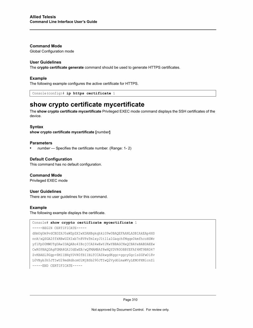
Allied Telesis Command Line Interface User’s Guide
Command ModeGlobal Configuration mode
User GuidelinesThe crypto certificate generate command should be used to generate HTTPS certificates.
ExampleThe following example configures the active certificate for HTTPS.
show crypto certificate mycertificateThe show crypto certificate mycertificate Privileged EXEC mode command displays the SSH certificates of the device.
Syntaxshow crypto certificate mycertificate [number]
Parameters• number — Specifies the certificate number. (Range: 1- 2)
Default ConfigurationThis command has no default configuration.
Command ModePrivileged EXEC mode
User GuidelinesThere are no user guidelines for this command.
ExampleThe following example displays the certificate.
Console(config)# ip https certificate 1
Console# show crypto certificate mycertificate 1-----BEGIN CERTIFICATE-----
dHmUgUm9vdCBDZXJ0aWZpZXIwXDANBgkqhkiG9w0BAQEFAANLADBIAkEAp4HS
nnH/xQSGA2ffkRBwU2XIxb7n8VPsTm1xyJ1t11a1GaqchfMqqe0kmfhcoHSWryf1FpD0MWOTgDAwIDAQABo4IBojCCAZ4wEwYJKwYBBAGCNxQCBAYeBABDAEEw
CwR0PBAQDAgFGMA8GA1UdEwEB/wQFMAMBAf8wHQYDVR0OBBYEFAf4MT9BRD47
ZvKBAEL9Ggp+6MIIBNgYDVR0fBIIBLTCCASkwgdKggc+ggcyGgclsZGFwOi8vL0VByb3h5JTIwU29mdHdhcmUlMjBSb290JTIwQ2VydGlmaWVyLENOPXNlcnZl
-----END CERTIFICATE-----
Page 310
Not approved by Document Control. For review only.
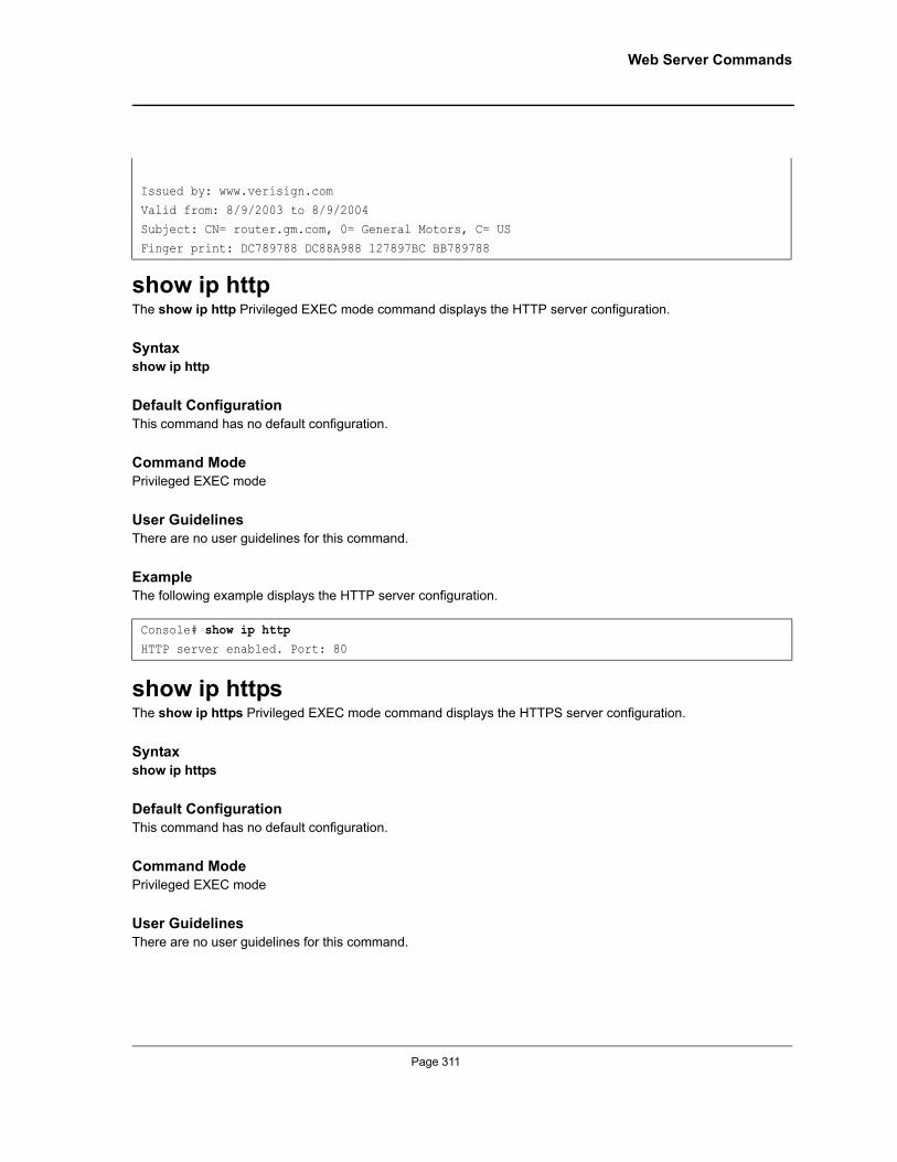
Web Server Commands
show ip httpThe show ip http Privileged EXEC mode command displays the HTTP server configuration.
Syntaxshow ip http
Default ConfigurationThis command has no default configuration.
Command ModePrivileged EXEC mode
User GuidelinesThere are no user guidelines for this command.
ExampleThe following example displays the HTTP server configuration.
show ip httpsThe show ip https Privileged EXEC mode command displays the HTTPS server configuration.
Syntaxshow ip https
Default ConfigurationThis command has no default configuration.
Command ModePrivileged EXEC mode
User GuidelinesThere are no user guidelines for this command.
Issued by: www.verisign.com
Valid from: 8/9/2003 to 8/9/2004Subject: CN= router.gm.com, 0= General Motors, C= US
Finger print: DC789788 DC88A988 127897BC BB789788
Console# show ip httpHTTP server enabled. Port: 80
Page 311
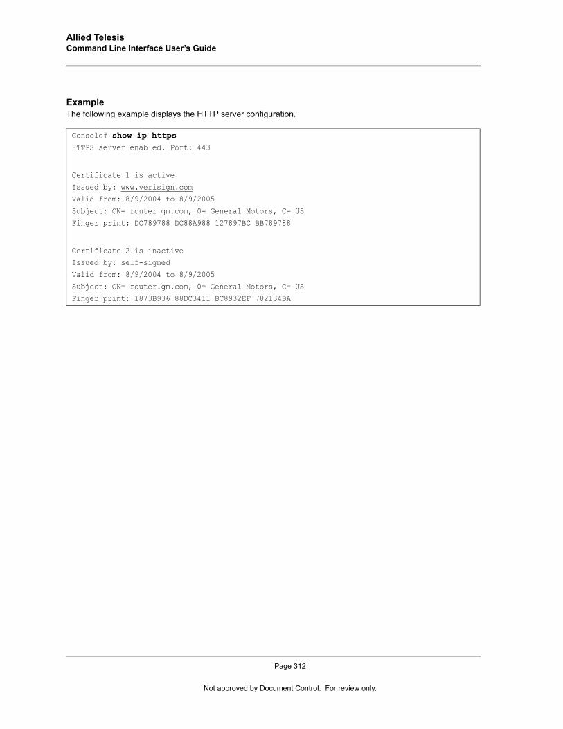
Allied Telesis Command Line Interface User’s Guide
ExampleThe following example displays the HTTP server configuration.
Console# show ip httpsHTTPS server enabled. Port: 443
Certificate 1 is active
Issued by: www.verisign.comValid from: 8/9/2004 to 8/9/2005
Subject: CN= router.gm.com, 0= General Motors, C= US
Finger print: DC789788 DC88A988 127897BC BB789788
Certificate 2 is inactiveIssued by: self-signed
Valid from: 8/9/2004 to 8/9/2005
Subject: CN= router.gm.com, 0= General Motors, C= USFinger print: 1873B936 88DC3411 BC8932EF 782134BA
Page 312
Not approved by Document Control. For review only.
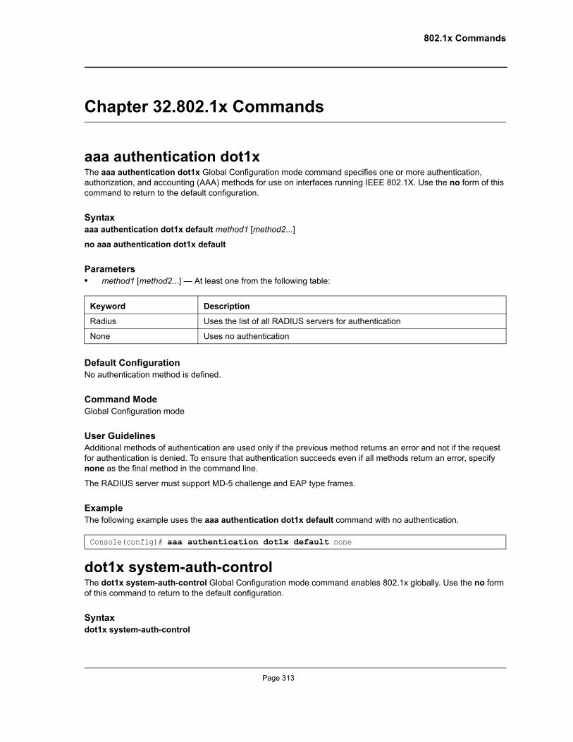
802.1x Commands
Chapter 32.802.1x Commands
aaa authentication dot1x The aaa authentication dot1x Global Configuration mode command specifies one or more authentication, authorization, and accounting (AAA) methods for use on interfaces running IEEE 802.1X. Use the no form of this command to return to the default configuration.
Syntaxaaa authentication dot1x default method1 [method2...]
no aaa authentication dot1x default
Parameters• method1 [method2...] — At least one from the following table:
Default ConfigurationNo authentication method is defined.
Command Mode Global Configuration mode
User Guidelines Additional methods of authentication are used only if the previous method returns an error and not if the request for authentication is denied. To ensure that authentication succeeds even if all methods return an error, specify none as the final method in the command line.
The RADIUS server must support MD-5 challenge and EAP type frames.
ExampleThe following example uses the aaa authentication dot1x default command with no authentication.
dot1x system-auth-controlThe dot1x system-auth-control Global Configuration mode command enables 802.1x globally. Use the no form of this command to return to the default configuration.
Syntax dot1x system-auth-control
Keyword Description
Radius Uses the list of all RADIUS servers for authentication
None Uses no authentication
Console(config)# aaa authentication dot1x default none
Page 313

Allied Telesis Command Line Interface User’s Guide
no dot1x system-auth-control
Default Configuration802.1x is disabled globally.
Command Modes Global Configuration mode
User GuidelinesThere are no user guidelines for this command.
ExampleThe following example enables 802.1x globally.
dot1x port-controlThe dot1x port-control Interface Configuration mode command enables manually controlling the authorization state of the port. Use the no form of this command to return to the default configuration.
Syntaxdot1x port-control {auto | force-authorized | force-unauthorized}
no dot1x port-control
Parameters• auto — Enables 802.1X authentication on the interface and causes the port to transition to the authorized or
unauthorized state based on the 802.1X authentication exchange between the port and the client.• force-authorized — Disables 802.1X authentication on the interface and causes the port to transition to the
authorized state without any authentication exchange required. The port resends and receives normal traffic without 802.1X-based authentication of the client.
• force-unauthorized — Denies all access through this interface by forcing the port to transition to the unauthorized state and ignoring all attempts by the client to authenticate. The device cannot provide authentication services to the client through the interface.
Default ConfigurationPort is in the force-authorized state
Command Mode Interface Configuration (Ethernet)
User GuidelinesIt is recommended to disable spanning tree or to enable spanning-tree PortFast mode on 802.1x edge ports (ports in auto state that are connected to end stations), in order to get immediately to the forwarding state after successful authentication.
Console(config)# dot1x system-auth-control
Page 314
Not approved by Document Control. For review only.
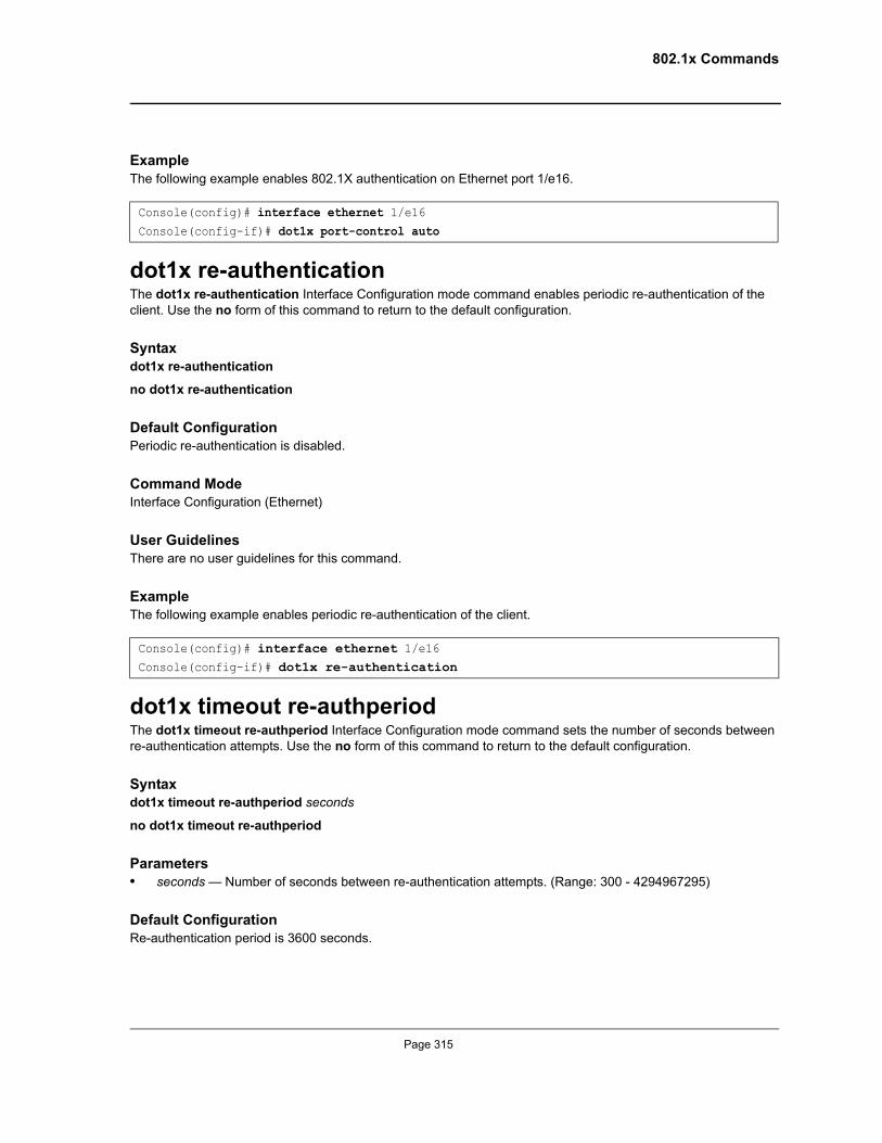
802.1x Commands
ExampleThe following example enables 802.1X authentication on Ethernet port 1/e16.
dot1x re-authenticationThe dot1x re-authentication Interface Configuration mode command enables periodic re-authentication of the client. Use the no form of this command to return to the default configuration.
Syntaxdot1x re-authentication
no dot1x re-authentication
Default ConfigurationPeriodic re-authentication is disabled.
Command Mode Interface Configuration (Ethernet)
User GuidelinesThere are no user guidelines for this command.
ExampleThe following example enables periodic re-authentication of the client.
dot1x timeout re-authperiodThe dot1x timeout re-authperiod Interface Configuration mode command sets the number of seconds between re-authentication attempts. Use the no form of this command to return to the default configuration.
Syntaxdot1x timeout re-authperiod seconds
no dot1x timeout re-authperiod
Parameters• seconds — Number of seconds between re-authentication attempts. (Range: 300 - 4294967295)
Default ConfigurationRe-authentication period is 3600 seconds.
Console(config)# interface ethernet 1/e16Console(config-if)# dot1x port-control auto
Console(config)# interface ethernet 1/e16Console(config-if)# dot1x re-authentication
Page 315
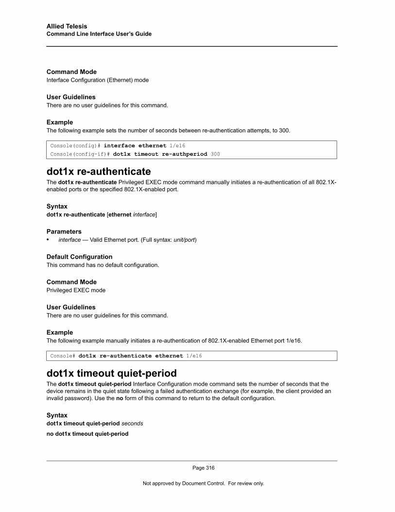
Allied Telesis Command Line Interface User’s Guide
Command Mode Interface Configuration (Ethernet) mode
User GuidelinesThere are no user guidelines for this command.
ExampleThe following example sets the number of seconds between re-authentication attempts, to 300.
dot1x re-authenticateThe dot1x re-authenticate Privileged EXEC mode command manually initiates a re-authentication of all 802.1X-enabled ports or the specified 802.1X-enabled port.
Syntaxdot1x re-authenticate [ethernet interface]
Parameters• interface — Valid Ethernet port. (Full syntax: unit/port)
Default ConfigurationThis command has no default configuration.
Command Mode Privileged EXEC mode
User GuidelinesThere are no user guidelines for this command.
ExampleThe following example manually initiates a re-authentication of 802.1X-enabled Ethernet port 1/e16.
dot1x timeout quiet-periodThe dot1x timeout quiet-period Interface Configuration mode command sets the number of seconds that the device remains in the quiet state following a failed authentication exchange (for example, the client provided an invalid password). Use the no form of this command to return to the default configuration.
Syntaxdot1x timeout quiet-period seconds
no dot1x timeout quiet-period
Console(config)# interface ethernet 1/e16Console(config-if)# dot1x timeout re-authperiod 300
Console# dot1x re-authenticate ethernet 1/e16
Page 316
Not approved by Document Control. For review only.
802.1x Commands
Parameters• seconds — Specifies the time in seconds that the device remains in the quiet state following a failed
authentication exchange with the client. (Range: 0 - 65535 seconds)
Default ConfigurationQuiet period is 60 seconds.
Command Mode Interface Configuration (Ethernet) mode
User GuidelinesDuring the quiet period, the device does not accept or initiate authentication requests.
The default value of this command should only be changed to adjust for unusual circumstances, such as unreliable links or specific behavioral problems with certain clients and authentication servers.
To provide a faster response time to the user, a smaller number than the default value should be entered.
ExampleThe following example sets the number of seconds that the device remains in the quiet state following a failed authentication exchange to 3600.
dot1x timeout tx-periodThe dot1x timeout tx-period Interface Configuration mode command sets the number of seconds that the device waits for a response to an Extensible Authentication Protocol (EAP)-request/identity frame from the client before resending the request. Use the no form of this command to return to the default configuration.
Syntaxdot1x timeout tx-period seconds
no dot1x timeout tx-period
Parameters• seconds — Specifies the time in seconds that the device waits for a response to an EAP-request/identity
frame from the client before resending the request. (Range: 30-65535 seconds)
Default ConfigurationTimeout period is 30 seconds.
Command Mode Interface Configuration (Ethernet) mode
Console(config)# interface ethernet 1/e16Console(config-if)# dot1x timeout quiet-period 3600
Page 317
Allied Telesis Command Line Interface User’s Guide
User GuidelinesThe default value of this command should be changed only to adjust for unusual circumstances, such as unreliable links or specific behavioral problems with certain clients. and authentication servers
ExampleThe following command sets the number of seconds that the device waits for a response to an EAP-request/identity frame, to 3600 seconds.
dot1x max-reqThe dot1x max-req Interface Configuration mode command sets the maximum number of times that the device sends an Extensible Authentication Protocol (EAP)-request/identity frame (assuming that no response is received) to the client, before restarting the authentication process. Use the no form of this command to return to the default configuration.
Syntaxdot1x max-req count
no dot1x max-req
Parameters• count — Number of times that the device sends an EAP-request/identity frame before restarting the
authentication process. (Range: 1-10)
Default ConfigurationThe default number of times is 2.
Command Mode Interface Configuration (Ethernet) mode
User GuidelinesThe default value of this command should be changed only to adjust for unusual circumstances, such as unreliable links or specific behavioral problems with certain clients. and authentication servers
ExampleThe following example sets the number of times that the device sends an EAP-request/identity frame to 6 .
dot1x timeout supp-timeoutThe dot1x timeout supp-timeout Interface Configuration mode command sets the time for the retransmission of an Extensible Authentication Protocol (EAP)-request frame to the client. Use the no form of this command to return to the default configuration.
Console(config)# interface ethernet 1/e16Console(config-if)# dot1x timeout tx-period 3600
Console(config)# interface ethernet 1/e16Console(config-if)# dot1x max-req 6
Page 318
Not approved by Document Control. For review only.
802.1x Commands
Syntaxdot1x timeout supp-timeout seconds
no dot1x timeout supp-timeout
Parameters• seconds — Time in seconds that the device waits for a response to an EAP-request frame from the client
before resending the request. (Range: 1- 65535 seconds)
Default ConfigurationDefault timeout period is 30 seconds.
Command Mode Interface configuration (Ethernet) mode
User Guidelines The default value of this command should be changed only to adjust for unusual circumstances, such as unreliable links or specific behavioral problems with certain clients. and authentication servers
ExampleThe following example sets the timeout period before retransmitting an EAP-request frame to the client to 3600 seconds.
dot1x timeout server-timeoutThe dot1x timeout server-timeout Interface Configuration mode command sets the time that the device waits for a response from the authentication server. Use the no form of this command to return to the default configuration.
Syntaxdot1x timeout server-timeout seconds
no dot1x timeout server-timeout
Parameters• seconds — Time in seconds that the device waits for a response from the authentication server.
(Range: 1-65535 seconds)
Default ConfigurationThe timeout period is 30 seconds.
Command Mode Interface configuration (Ethernet) mode
Console(config-if)# dot1x timeout supp-timeout 3600
Page 319
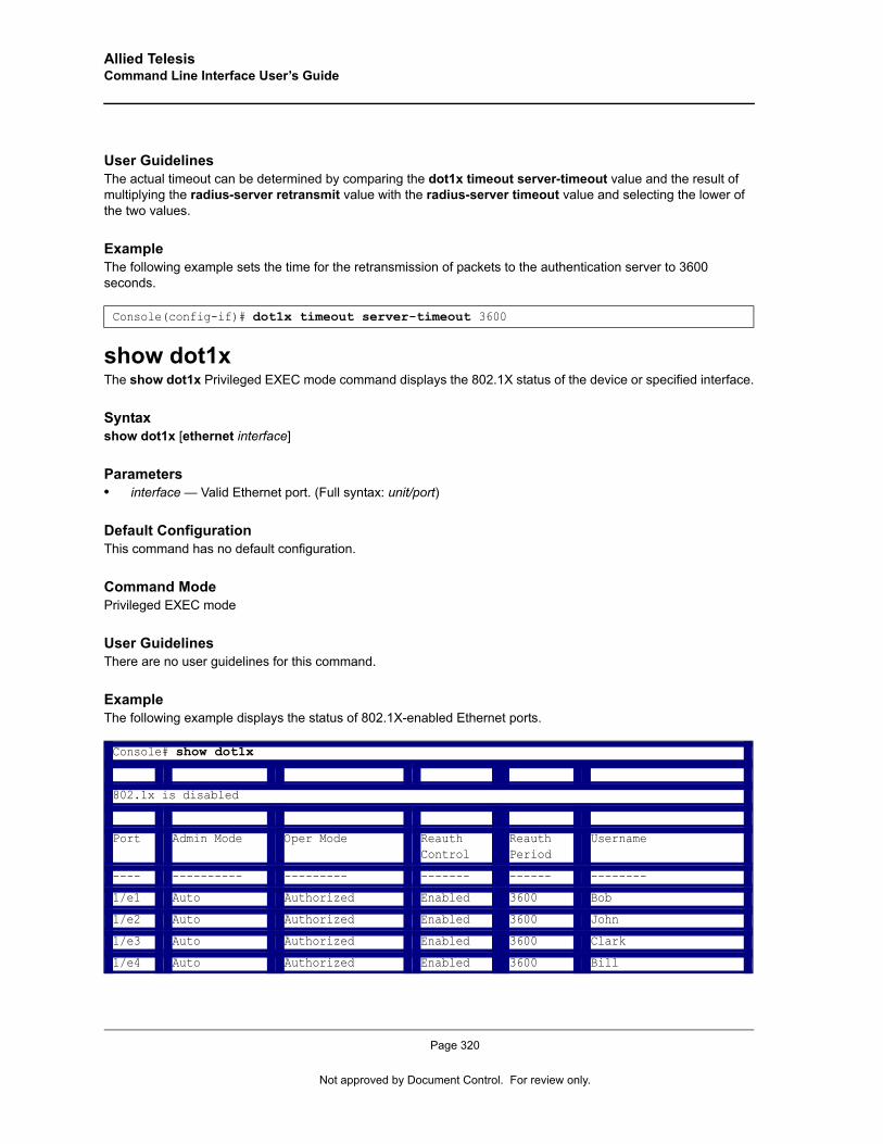
Allied Telesis Command Line Interface User’s Guide
User Guidelines The actual timeout can be determined by comparing the dot1x timeout server-timeout value and the result of multiplying the radius-server retransmit value with the radius-server timeout value and selecting the lower of the two values.
ExampleThe following example sets the time for the retransmission of packets to the authentication server to 3600 seconds.
show dot1xThe show dot1x Privileged EXEC mode command displays the 802.1X status of the device or specified interface.
Syntaxshow dot1x [ethernet interface]
Parameters• interface — Valid Ethernet port. (Full syntax: unit/port)
Default ConfigurationThis command has no default configuration.
Command Mode Privileged EXEC mode
User Guidelines There are no user guidelines for this command.
ExampleThe following example displays the status of 802.1X-enabled Ethernet ports.
Console(config-if)# dot1x timeout server-timeout 3600
Console# show dot1x
802.1x is disabled
Port Admin Mode Oper Mode Reauth Control
Reauth Period
Username
---- ---------- --------- ------- ------ --------
1/e1 Auto Authorized Enabled 3600 Bob
1/e2 Auto Authorized Enabled 3600 John
1/e3 Auto Authorized Enabled 3600 Clark
1/e4 Auto Authorized Enabled 3600 Bill
Page 320
Not approved by Document Control. For review only.
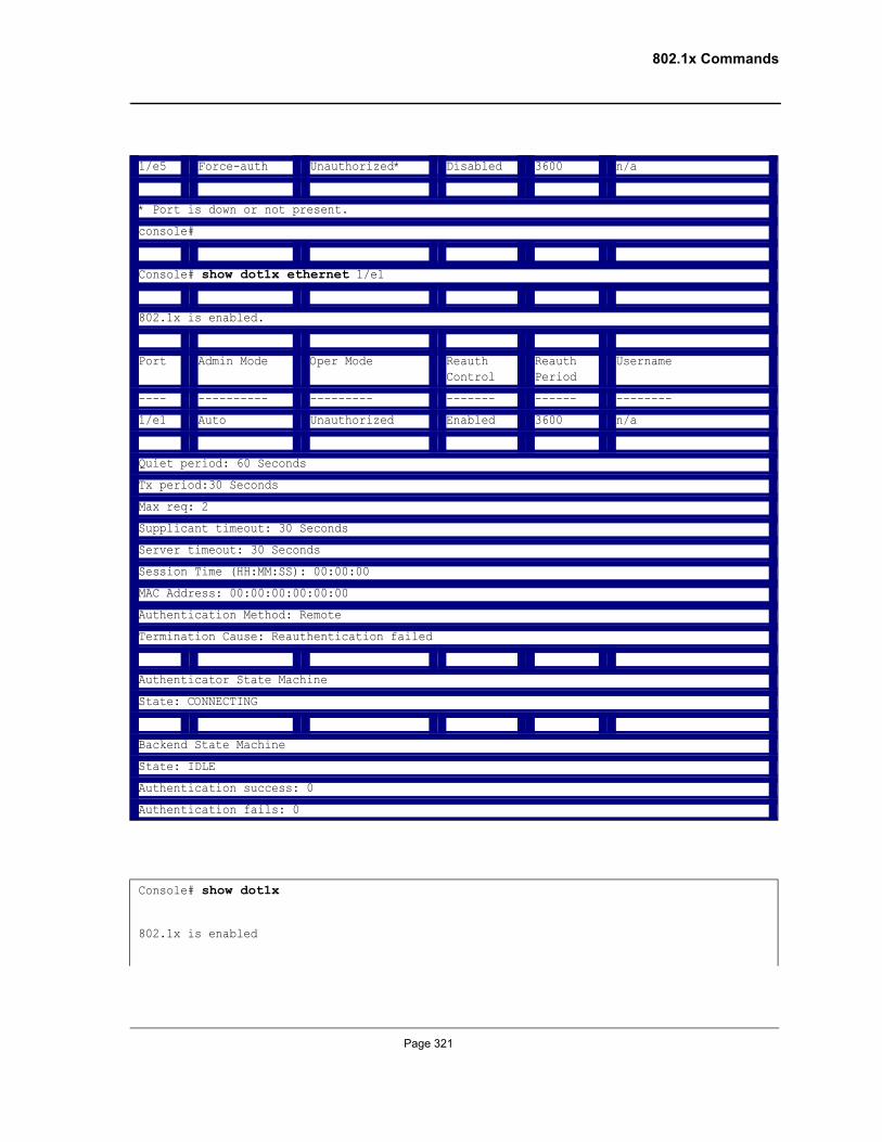
802.1x Commands
1/e5 Force-auth Unauthorized* Disabled 3600 n/a
* Port is down or not present.
console#
Console# show dot1x ethernet 1/e1
802.1x is enabled.
Port Admin Mode Oper Mode Reauth Control
Reauth Period
Username
---- ---------- --------- ------- ------ --------
1/e1 Auto Unauthorized Enabled 3600 n/a
Quiet period: 60 Seconds
Tx period:30 Seconds
Max req: 2
Supplicant timeout: 30 Seconds
Server timeout: 30 Seconds
Session Time (HH:MM:SS): 00:00:00
MAC Address: 00:00:00:00:00:00
Authentication Method: Remote
Termination Cause: Reauthentication failed
Authenticator State Machine
State: CONNECTING
Backend State Machine
State: IDLE
Authentication success: 0
Authentication fails: 0
Console# show dot1x
802.1x is enabled
Page 321
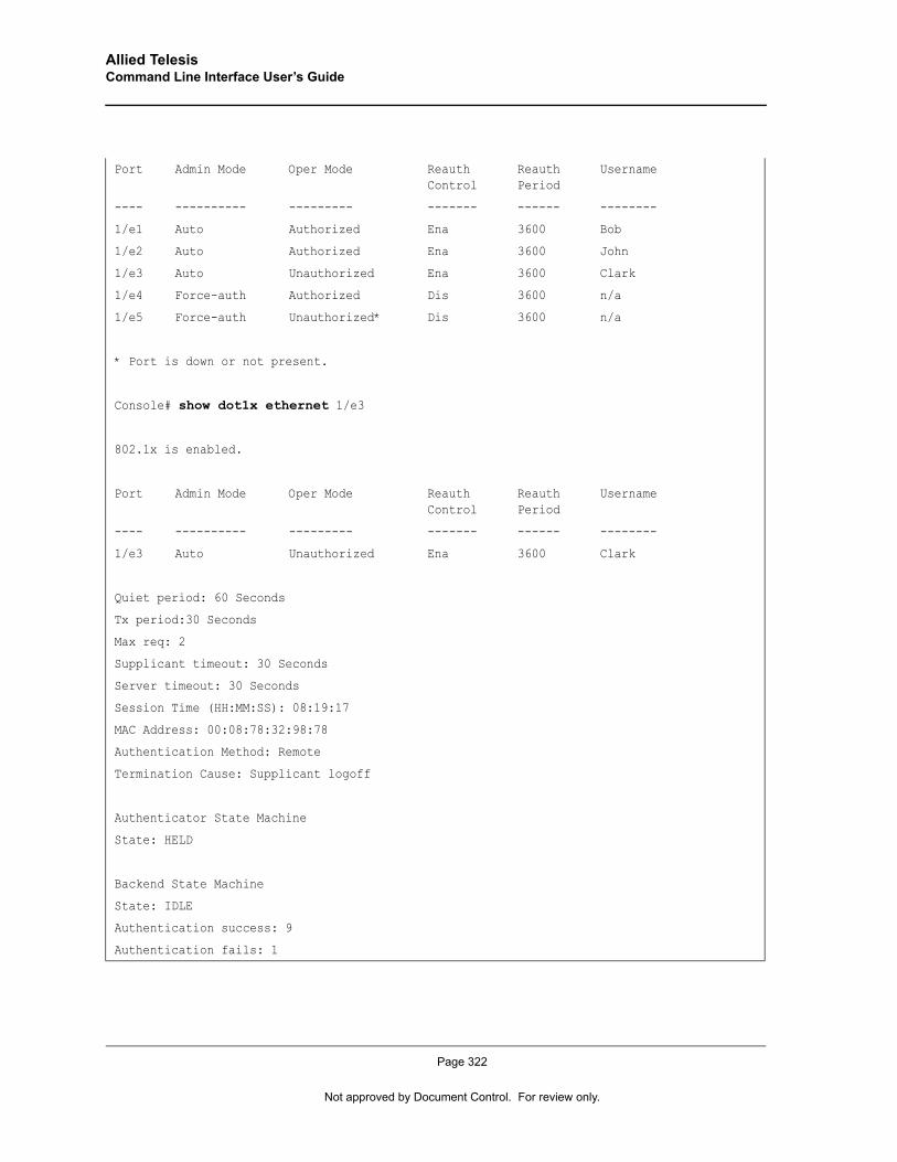
Allied Telesis Command Line Interface User’s Guide
Port Admin Mode Oper Mode Reauth Control
Reauth Period
Username
---- ---------- --------- ------- ------ --------
1/e1 Auto Authorized Ena 3600 Bob
1/e2 Auto Authorized Ena 3600 John
1/e3 Auto Unauthorized Ena 3600 Clark
1/e4 Force-auth Authorized Dis 3600 n/a
1/e5 Force-auth Unauthorized* Dis 3600 n/a
* Port is down or not present.
Console# show dot1x ethernet 1/e3
802.1x is enabled.
Port Admin Mode Oper Mode Reauth Control
Reauth Period
Username
---- ---------- --------- ------- ------ --------
1/e3 Auto Unauthorized Ena 3600 Clark
Quiet period: 60 Seconds
Tx period:30 Seconds
Max req: 2
Supplicant timeout: 30 Seconds
Server timeout: 30 Seconds
Session Time (HH:MM:SS): 08:19:17
MAC Address: 00:08:78:32:98:78
Authentication Method: Remote
Termination Cause: Supplicant logoff
Authenticator State Machine
State: HELD
Backend State Machine
State: IDLE
Authentication success: 9
Authentication fails: 1
Page 322
Not approved by Document Control. For review only.
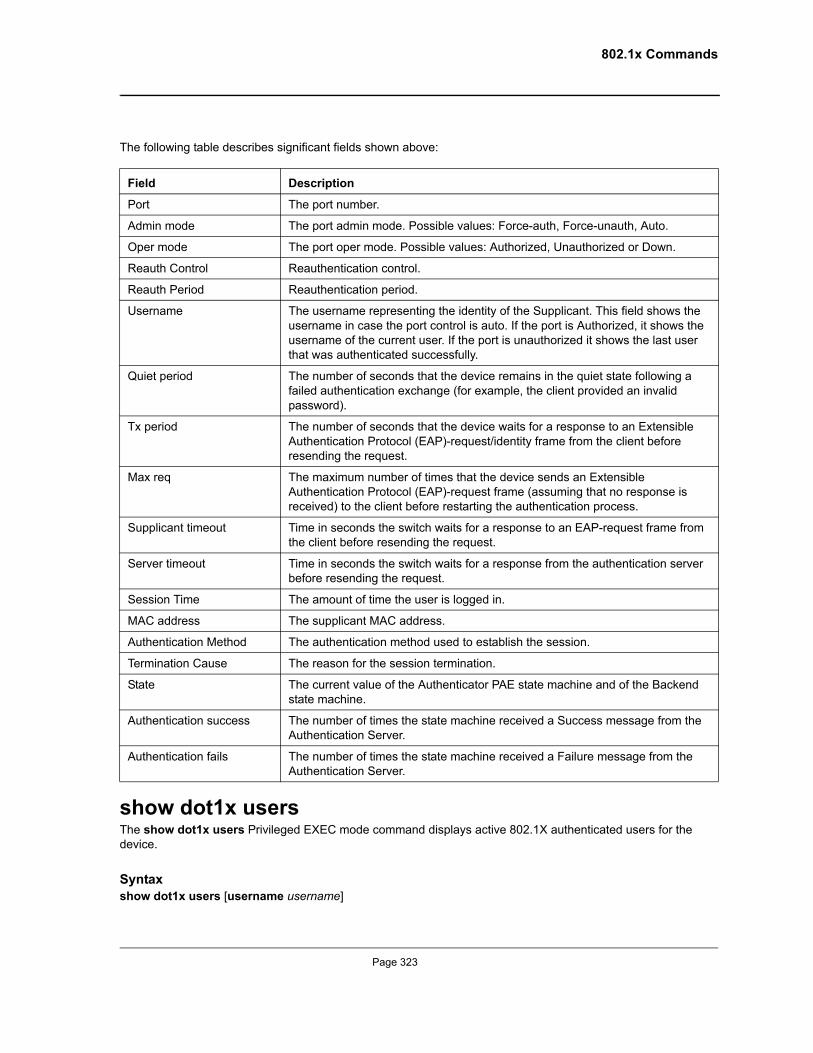
802.1x Commands
The following table describes significant fields shown above:
show dot1x usersThe show dot1x users Privileged EXEC mode command displays active 802.1X authenticated users for the device.
Syntaxshow dot1x users [username username]
Field Description
Port The port number.
Admin mode The port admin mode. Possible values: Force-auth, Force-unauth, Auto.
Oper mode The port oper mode. Possible values: Authorized, Unauthorized or Down.
Reauth Control Reauthentication control.
Reauth Period Reauthentication period.
Username The username representing the identity of the Supplicant. This field shows the username in case the port control is auto. If the port is Authorized, it shows the username of the current user. If the port is unauthorized it shows the last user that was authenticated successfully.
Quiet period The number of seconds that the device remains in the quiet state following a failed authentication exchange (for example, the client provided an invalid password).
Tx period The number of seconds that the device waits for a response to an Extensible Authentication Protocol (EAP)-request/identity frame from the client before resending the request.
Max req The maximum number of times that the device sends an Extensible Authentication Protocol (EAP)-request frame (assuming that no response is received) to the client before restarting the authentication process.
Supplicant timeout Time in seconds the switch waits for a response to an EAP-request frame from the client before resending the request.
Server timeout Time in seconds the switch waits for a response from the authentication server before resending the request.
Session Time The amount of time the user is logged in.
MAC address The supplicant MAC address.
Authentication Method The authentication method used to establish the session.
Termination Cause The reason for the session termination.
State The current value of the Authenticator PAE state machine and of the Backend state machine.
Authentication success The number of times the state machine received a Success message from the Authentication Server.
Authentication fails The number of times the state machine received a Failure message from the Authentication Server.
Page 323
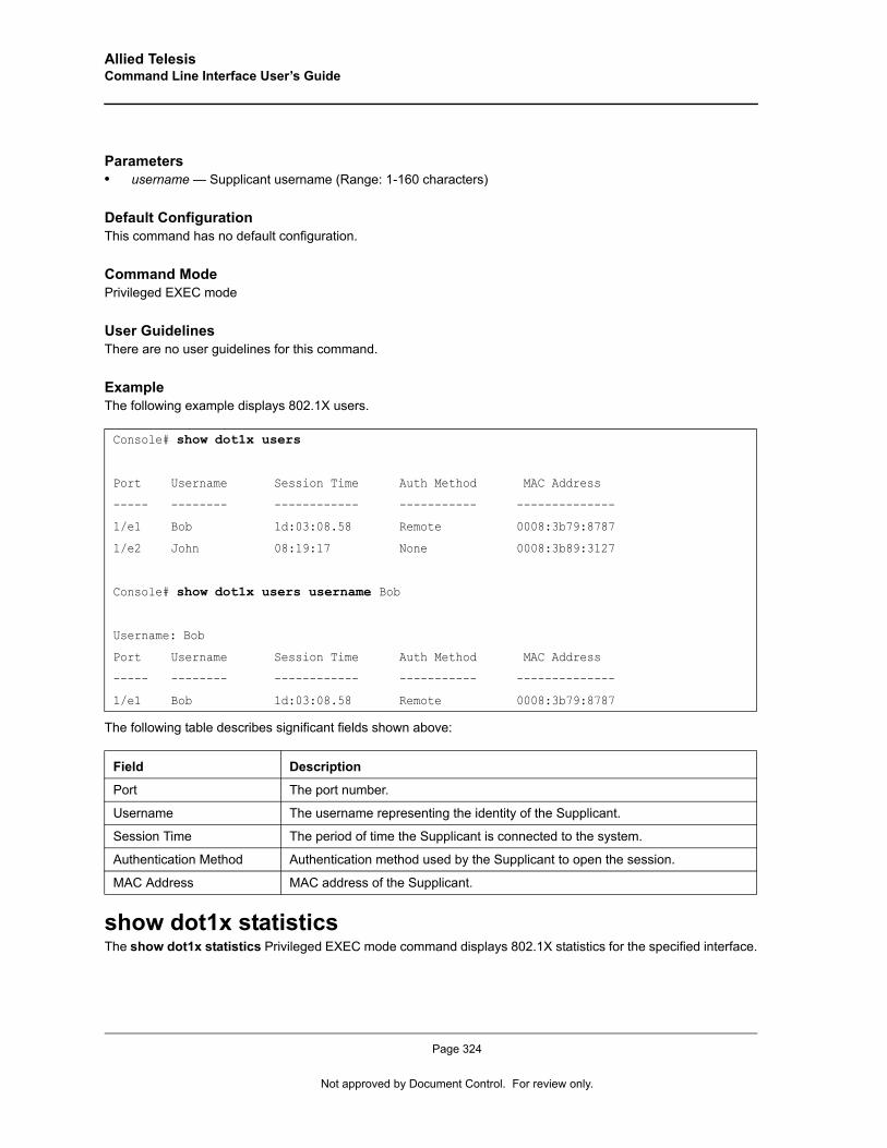
Allied Telesis Command Line Interface User’s Guide
Parameters• username — Supplicant username (Range: 1-160 characters)
Default ConfigurationThis command has no default configuration.
Command Mode Privileged EXEC mode
User Guidelines There are no user guidelines for this command.
ExampleThe following example displays 802.1X users.
The following table describes significant fields shown above:
show dot1x statisticsThe show dot1x statistics Privileged EXEC mode command displays 802.1X statistics for the specified interface.
Console# show dot1x users
Port Username Session Time Auth Method MAC Address
----- -------- ------------ ----------- --------------
1/e1 Bob 1d:03:08.58 Remote 0008:3b79:8787
1/e2 John 08:19:17 None 0008:3b89:3127
Console# show dot1x users username Bob
Username: Bob
Port Username Session Time Auth Method MAC Address
----- -------- ------------ ----------- --------------
1/e1 Bob 1d:03:08.58 Remote 0008:3b79:8787
Field Description
Port The port number.
Username The username representing the identity of the Supplicant.
Session Time The period of time the Supplicant is connected to the system.
Authentication Method Authentication method used by the Supplicant to open the session.
MAC Address MAC address of the Supplicant.
Page 324
Not approved by Document Control. For review only.
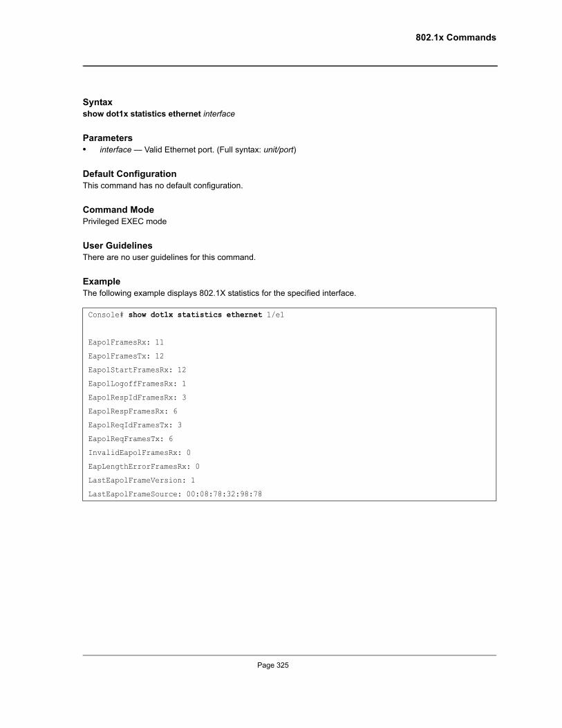
802.1x Commands
Syntaxshow dot1x statistics ethernet interface
Parameters• interface — Valid Ethernet port. (Full syntax: unit/port)
Default ConfigurationThis command has no default configuration.
Command Mode Privileged EXEC mode
User Guidelines There are no user guidelines for this command.
ExampleThe following example displays 802.1X statistics for the specified interface.
Console# show dot1x statistics ethernet 1/e1
EapolFramesRx: 11
EapolFramesTx: 12
EapolStartFramesRx: 12
EapolLogoffFramesRx: 1
EapolRespIdFramesRx: 3
EapolRespFramesRx: 6
EapolReqIdFramesTx: 3
EapolReqFramesTx: 6
InvalidEapolFramesRx: 0
EapLengthErrorFramesRx: 0
LastEapolFrameVersion: 1
LastEapolFrameSource: 00:08:78:32:98:78
Page 325
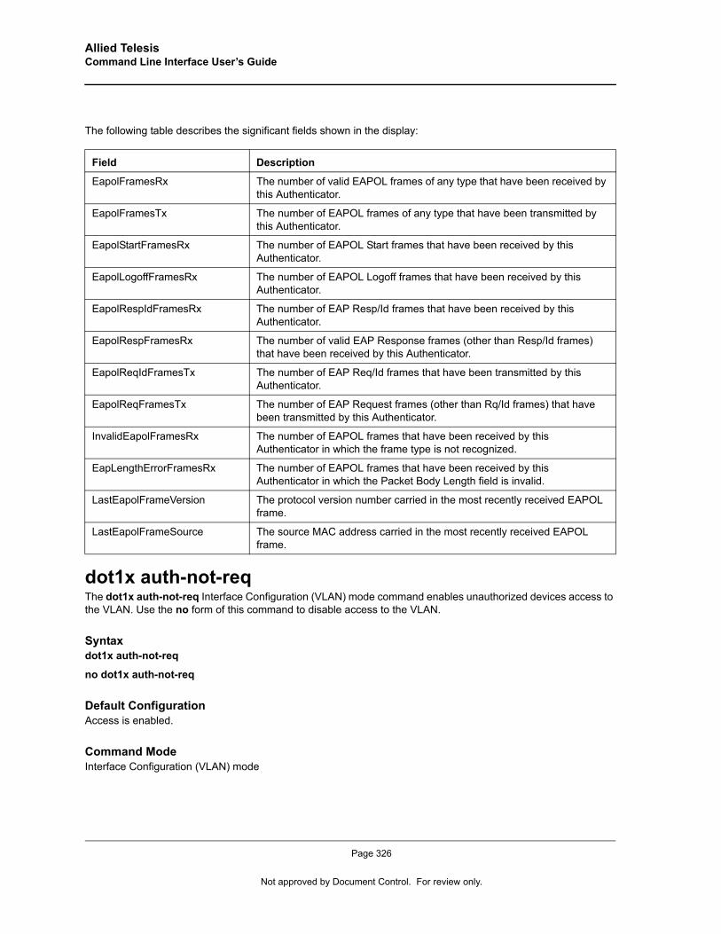
Allied Telesis Command Line Interface User’s Guide
The following table describes the significant fields shown in the display:
dot1x auth-not-reqThe dot1x auth-not-req Interface Configuration (VLAN) mode command enables unauthorized devices access to the VLAN. Use the no form of this command to disable access to the VLAN.
Syntaxdot1x auth-not-req
no dot1x auth-not-req
Default ConfigurationAccess is enabled.
Command Mode Interface Configuration (VLAN) mode
Field Description
EapolFramesRx The number of valid EAPOL frames of any type that have been received by this Authenticator.
EapolFramesTx The number of EAPOL frames of any type that have been transmitted by this Authenticator.
EapolStartFramesRx The number of EAPOL Start frames that have been received by this Authenticator.
EapolLogoffFramesRx The number of EAPOL Logoff frames that have been received by this Authenticator.
EapolRespIdFramesRx The number of EAP Resp/Id frames that have been received by this Authenticator.
EapolRespFramesRx The number of valid EAP Response frames (other than Resp/Id frames) that have been received by this Authenticator.
EapolReqIdFramesTx The number of EAP Req/Id frames that have been transmitted by this Authenticator.
EapolReqFramesTx The number of EAP Request frames (other than Rq/Id frames) that have been transmitted by this Authenticator.
InvalidEapolFramesRx The number of EAPOL frames that have been received by this Authenticator in which the frame type is not recognized.
EapLengthErrorFramesRx The number of EAPOL frames that have been received by this Authenticator in which the Packet Body Length field is invalid.
LastEapolFrameVersion The protocol version number carried in the most recently received EAPOL frame.
LastEapolFrameSource The source MAC address carried in the most recently received EAPOL frame.
Page 326
Not approved by Document Control. For review only.
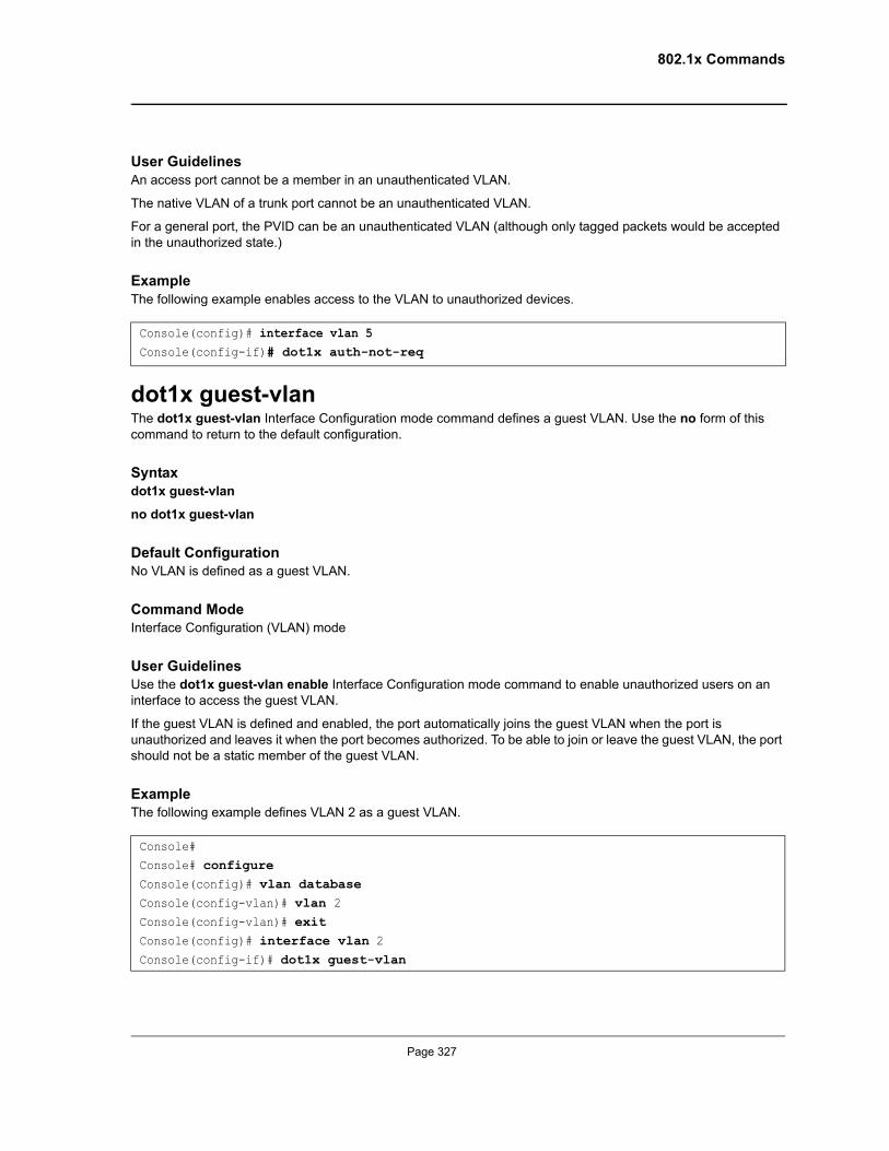
802.1x Commands
User GuidelinesAn access port cannot be a member in an unauthenticated VLAN.
The native VLAN of a trunk port cannot be an unauthenticated VLAN.
For a general port, the PVID can be an unauthenticated VLAN (although only tagged packets would be accepted in the unauthorized state.)
ExampleThe following example enables access to the VLAN to unauthorized devices.
dot1x guest-vlanThe dot1x guest-vlan Interface Configuration mode command defines a guest VLAN. Use the no form of this command to return to the default configuration.
Syntaxdot1x guest-vlan
no dot1x guest-vlan
Default ConfigurationNo VLAN is defined as a guest VLAN.
Command ModeInterface Configuration (VLAN) mode
User GuidelinesUse the dot1x guest-vlan enable Interface Configuration mode command to enable unauthorized users on an interface to access the guest VLAN.
If the guest VLAN is defined and enabled, the port automatically joins the guest VLAN when the port is unauthorized and leaves it when the port becomes authorized. To be able to join or leave the guest VLAN, the port should not be a static member of the guest VLAN.
ExampleThe following example defines VLAN 2 as a guest VLAN.
Console(config)# interface vlan 5Console(config-if)# dot1x auth-not-req
Console#Console# configureConsole(config)# vlan databaseConsole(config-vlan)# vlan 2Console(config-vlan)# exitConsole(config)# interface vlan 2Console(config-if)# dot1x guest-vlan
Page 327
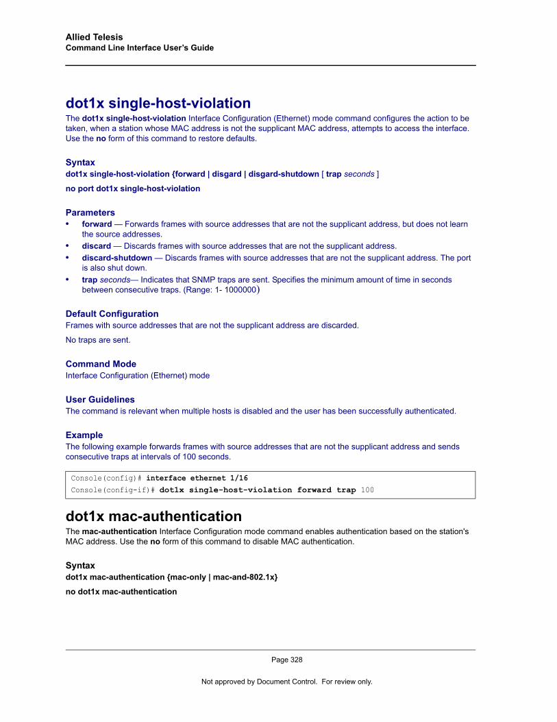
Allied Telesis Command Line Interface User’s Guide
dot1x single-host-violationThe dot1x single-host-violation Interface Configuration (Ethernet) mode command configures the action to be taken, when a station whose MAC address is not the supplicant MAC address, attempts to access the interface. Use the no form of this command to restore defaults.
Syntaxdot1x single-host-violation {forward | disgard | disgard-shutdown [ trap seconds ]
no port dot1x single-host-violation
Parameters• forward — Forwards frames with source addresses that are not the supplicant address, but does not learn
the source addresses.• discard — Discards frames with source addresses that are not the supplicant address.• discard-shutdown — Discards frames with source addresses that are not the supplicant address. The port
is also shut down.• trap seconds— Indicates that SNMP traps are sent. Specifies the minimum amount of time in seconds
between consecutive traps. (Range: 1- 1000000)
Default ConfigurationFrames with source addresses that are not the supplicant address are discarded.
No traps are sent.
Command Mode Interface Configuration (Ethernet) mode
User GuidelinesThe command is relevant when multiple hosts is disabled and the user has been successfully authenticated.
ExampleThe following example forwards frames with source addresses that are not the supplicant address and sends consecutive traps at intervals of 100 seconds.
dot1x mac-authenticationThe mac-authentication Interface Configuration mode command enables authentication based on the station's MAC address. Use the no form of this command to disable MAC authentication.
Syntaxdot1x mac-authentication {mac-only | mac-and-802.1x}
no dot1x mac-authentication
Console(config)# interface ethernet 1/16Console(config-if)# dot1x single-host-violation forward trap 100
Page 328
Not approved by Document Control. For review only.
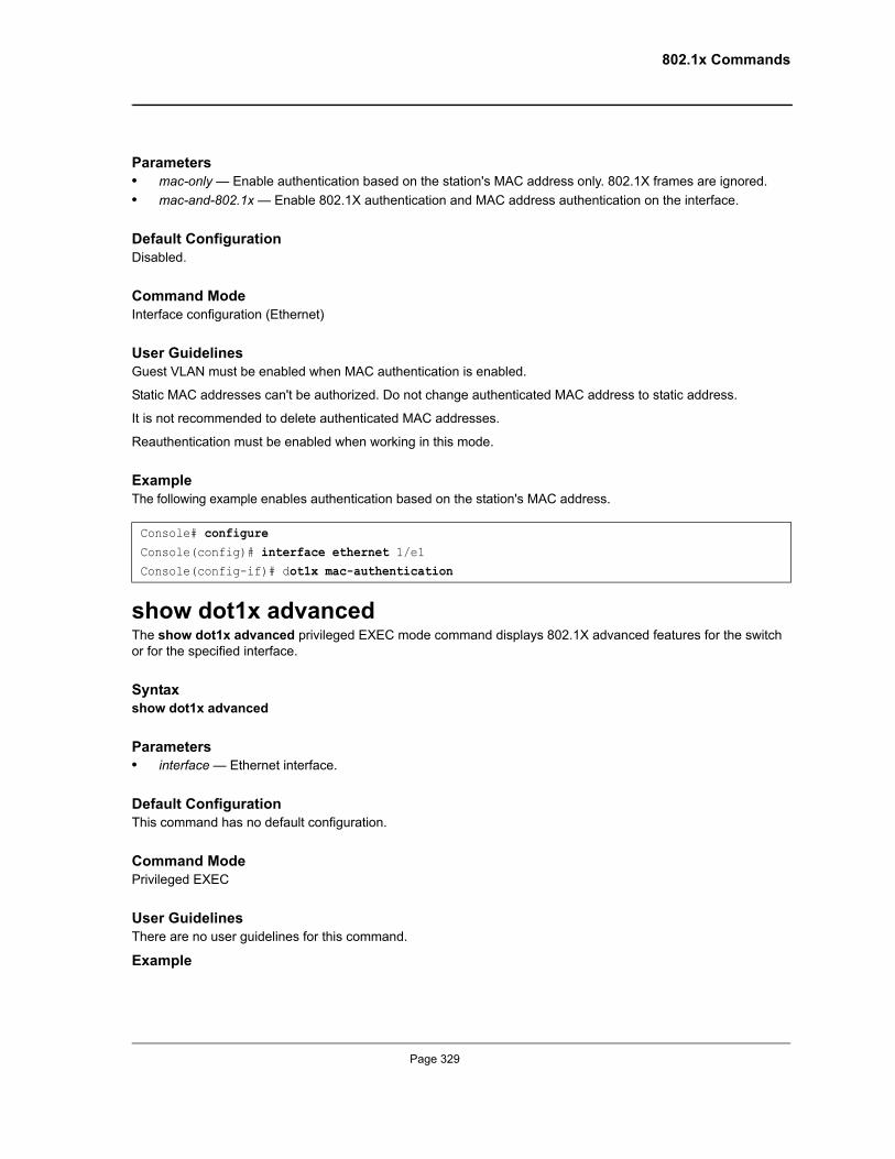
802.1x Commands
Parameters• mac-only — Enable authentication based on the station's MAC address only. 802.1X frames are ignored.• mac-and-802.1x — Enable 802.1X authentication and MAC address authentication on the interface.
Default ConfigurationDisabled.
Command ModeInterface configuration (Ethernet)
User GuidelinesGuest VLAN must be enabled when MAC authentication is enabled.
Static MAC addresses can't be authorized. Do not change authenticated MAC address to static address.
It is not recommended to delete authenticated MAC addresses.
Reauthentication must be enabled when working in this mode.
ExampleThe following example enables authentication based on the station's MAC address.
show dot1x advancedThe show dot1x advanced privileged EXEC mode command displays 802.1X advanced features for the switch or for the specified interface.
Syntaxshow dot1x advanced
Parameters• interface — Ethernet interface.
Default ConfigurationThis command has no default configuration.
Command ModePrivileged EXEC
User GuidelinesThere are no user guidelines for this command.
Example
Console# configureConsole(config)# interface ethernet 1/e1Console(config-if)# dot1x mac-authentication
Page 329

Allied Telesis Command Line Interface User’s Guide
The following example displays 802.1X advanced features for the switch.
dot1x guest-vlan enableThe dot1x guest-vlan enable Interface Configuration mode command enables unauthorized users on the interface access to the Guest VLAN. Use the no form of this command to disable access.
Syntaxdot1x guest-vlan enable
no dot1x guest-vlan enable
Console# show dot1x advanced
Guest VLAN: 3978
Unauthenticated VLANs: 91,92
Interface Multiple Hosts Guest VLAN MAC Authentication
--------- -------------- ---------- ----------
1/1 Disabled Enabled MAC-and-802.1X
1/2 Enabled Disabled Disabled
Console# show dot1x advanced ethernet 1/1
Guest VLAN: 2
Unauthenticated VLANs: 91,92
Interface Multiple Hosts Guest VLAN MAC Authentication
--------- -------------- ---------- ----------
1/1 Disabled Enabled MAC-and-802.1X
1/2 Enabled Disabled Disabled
Single host parameters
Violation action: Discard
Trap: Enabled
Trap frequency: 100
Status: Single-host locked
Violations since last trap: 9
Page 330
Not approved by Document Control. For review only.
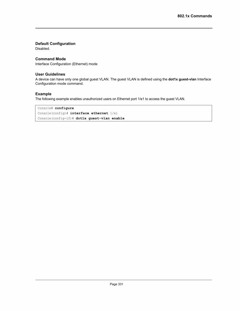
802.1x Commands
Default ConfigurationDisabled.
Command ModeInterface Configuration (Ethernet) mode
User GuidelinesA device can have only one global guest VLAN. The guest VLAN is defined using the dot1x guest-vlan Interface Configuration mode command.
ExampleThe following example enables unauthorized users on Ethernet port 1/e1 to access the guest VLAN.
Console# configureConsole(config)# interface ethernet 1/e1Console(config-if)# dot1x guest-vlan enable
Page 331
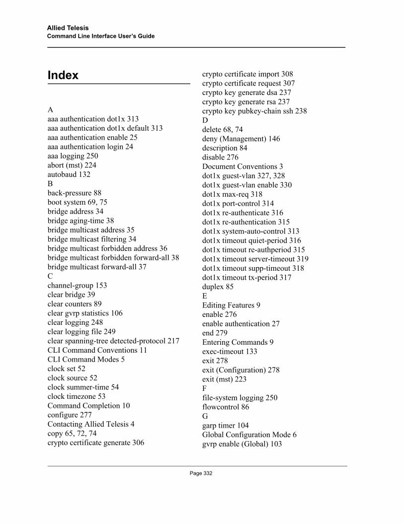
Allied TelesisCommand Line Interface User’s Guide
Index
Aaaa authentication dot1x 313aaa authentication dot1x default 313aaa authentication enable 25aaa authentication login 24aaa logging 250abort (mst) 224autobaud 132Bback-pressure 88boot system 69, 75bridge address 34bridge aging-time 38bridge multicast address 35bridge multicast filtering 34bridge multicast forbidden address 36bridge multicast forbidden forward-all 38bridge multicast forward-all 37Cchannel-group 153clear bridge 39clear counters 89clear gvrp statistics 106clear logging 248clear logging file 249clear spanning-tree detected-protocol 217CLI Command Conventions 11CLI Command Modes 5clock set 52clock source 52clock summer-time 54clock timezone 53Command Completion 10configure 277Contacting Allied Telesis 4copy 65, 72, 74crypto certificate generate 306
crypto certificate import 308crypto certificate request 307crypto key generate dsa 237crypto key generate rsa 237crypto key pubkey-chain ssh 238Ddelete 68, 74deny (Management) 146description 84disable 276Document Conventions 3dot1x guest-vlan 327, 328dot1x guest-vlan enable 330dot1x max-req 318dot1x port-control 314dot1x re-authenticate 316dot1x re-authentication 315dot1x system-auto-control 313dot1x timeout quiet-period 316dot1x timeout re-authperiod 315dot1x timeout server-timeout 319dot1x timeout supp-timeout 318dot1x timeout tx-period 317duplex 85EEditing Features 9enable 276enable authentication 27end 279Entering Commands 9exec-timeout 133exit 278exit (Configuration) 278exit (mst) 223Ffile-system logging 250flowcontrol 86Ggarp timer 104Global Configuration Mode 6gvrp enable (Global) 103
Page 332
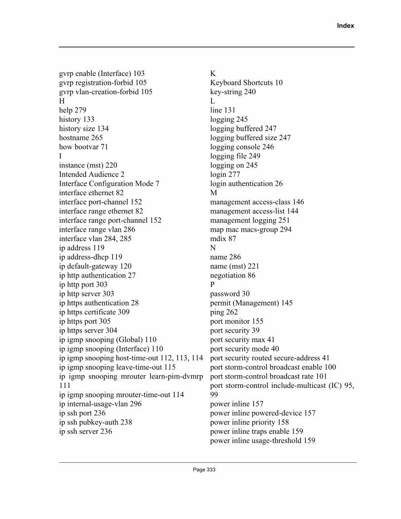
Index
gvrp enable (Interface) 103gvrp registration-forbid 105gvrp vlan-creation-forbid 105Hhelp 279history 133history size 134hostname 265how bootvar 71Iinstance (mst) 220Intended Audience 2Interface Configuration Mode 7interface ethernet 82interface port-channel 152interface range ethernet 82interface range port-channel 152interface range vlan 286interface vlan 284, 285ip address 119ip address-dhcp 119ip default-gateway 120ip http authentication 27ip http port 303ip http server 303ip https authentication 28ip https certificate 309ip https port 305ip https server 304ip igmp snooping (Global) 110ip igmp snooping (Interface) 110ip igmp snooping host-time-out 112, 113, 114ip igmp snooping leave-time-out 115ip igmp snooping mrouter learn-pim-dvmrp111ip igmp snooping mrouter-time-out 114ip internal-usage-vlan 296ip ssh port 236ip ssh pubkey-auth 238ip ssh server 236
KKeyboard Shortcuts 10key-string 240Lline 131logging 245logging buffered 247logging buffered size 247logging console 246logging file 249logging on 245login 277login authentication 26Mmanagement access-class 146management access-list 144management logging 251map mac macs-group 294mdix 87Nname 286name (mst) 221negotiation 86Ppassword 30permit (Management) 145ping 262port monitor 155port security 39port security max 41port security mode 40port security routed secure-address 41port storm-control broadcast enable 100port storm-control broadcast rate 101port storm-control include-multicast (IC) 95,99power inline 157power inline powered-device 157power inline priority 158power inline traps enable 159power inline usage-threshold 159
Page 333
Allied TelesisCommand Line Interface User’s Guide
Preface 1priority-queue out num-of-queues 165Privileged EXEC Mode 5Qqos 164qos cos 170qos map dscp-queue 169qos trust (Global) 170Rradius-server deadtime 175radius-server host 172radius-server key 173radius-server retransmit 173radius-server source-ip 174radius-server timeout 175rate-limit 165reload 264revision (mst) 222rmon alarm 184rmon collection history 180rmon event 187rmon table-size 190Sset interface active 90show (mst) 222show authentication methods 29show bridge address-table 42show bridge address-table count 44, 45show bridge address-table static 43show bridge multicast address-table 45show bridge multicast filtering 47show clock 61show copper-ports cable-length 150show copper-ports tdr 149show crypto certificate mycertificate 310show crypto key mypubkey 242show crypto key pubkey-chain ssh 243show dot1x 320show dot1x advanced 331show dot1x statistics 324show dot1x users 323
show gvrp configuration 106show gvrp error-statistics 108show gvrp statistics 107show history 281show interfaces advertise 90show interfaces counters 95show interfaces description 94show interfaces port-channel 153show interfaces status 93show interfaces switchport 299show ip http 311show ip https 311show ip igmp snooping groups 118show ip igmp snooping interface 117show ip igmp snooping mrouter 116show ip interface 121show ip ssh 241show line 135show logging 252show logging file 253show management access-class 148show management access-list 147show ports security 49show ports security addresses 50show ports storm-control 102show power inline 160show privilege 281show qos 164show qos interface 166show qos map 170show radius-servers 176show rmon alarm 186show rmon alarm-table 185show rmon collection history 180show rmon events 188show rmon history 181show rmon log 189show rmon statistics 178show running-config 69, 76show sessions 270show snmp 203
Page 334
Index
show snmp engineID 204show snmp filters 206show snmp groups 205show snmp users 207show snmp views 205show sntp configuration 62show sntp status 63show spanning-tree 224show stack 267show startup-config 70, 76show syslog-servers 256show system 271show tacacs 260show users 269show version 273show vlan 298show vlan internal usage 298show vlan macs-group 295shutdown 83snmp-server community 192snmp-server contact 201snmp-server enable traps 197snmp-server engineID local 196snmp-server filter 197snmp-server group 194snmp-server host 198snmp-server location 201snmp-server set 202snmp-server trap authentication 200snmp-server user 194snmp-server v3-host 199snmp-server view 193sntp anycast client enable 58sntp authenticate 56sntp authentication-key 55sntp broadcast client enable 57sntp client enable (Interface) 59sntp client poll timer 57sntp server 60sntp trusted-key 56sntp unicast client enable 59
sntp unicast client poll 60spanning-tree 208spanning-tree bpdu 215spanning-tree cost 212, 213spanning-tree disable 211spanning-tree forward-time 209spanning-tree hello-time 209spanning-tree link-type 214spanning-tree max-age 210spanning-tree mode 208spanning-tree mst configuration 220spanning-tree mst cost 219spanning-tree mst max-hops 218spanning-tree mst port-priority 218spanning-tree mst priority 217spanning-tree pathcost method 214spanning-tree portfast 213spanning-tree port-priority 213spanning-tree priority 211speed 84, 131stack change unit-id 267stack master 265stack reload 266Starting the CLI 8switchport access vlan 289switchport forbidden vlan 295switchport general acceptable-frame-typetagged-only 293switchport general allowed vlan 290switchport general map macs-group vlan 293switchport general pvid 291switchport mode 288switchport protected 287switchport trunk allowed vlan 289switchport trunk native vlan 290Ttacacs-server host 258tacacs-server key 259tacacs-server source-ip 260tacacs-server timeout 259Terminal Command Buffer 9
Page 335
Allied TelesisCommand Line Interface User’s Guide
terminal history 134terminal history size 135test copper-port tdr 149traffic-shape 166UUser EXEC Mode 5user-key 239username 30Vvlan 283vlan database 283Wwrr-queue cos-map 167
Page 336