8020 series snap-acting momentary pushbutton switches - c&k · snap-acting momentary pushbutton...
TRANSCRIPT
A-29
Dimensions are shown: Inches (mm) Specifications and dimensions subject to change
www.ckswitches.com
Pushb
utton
A
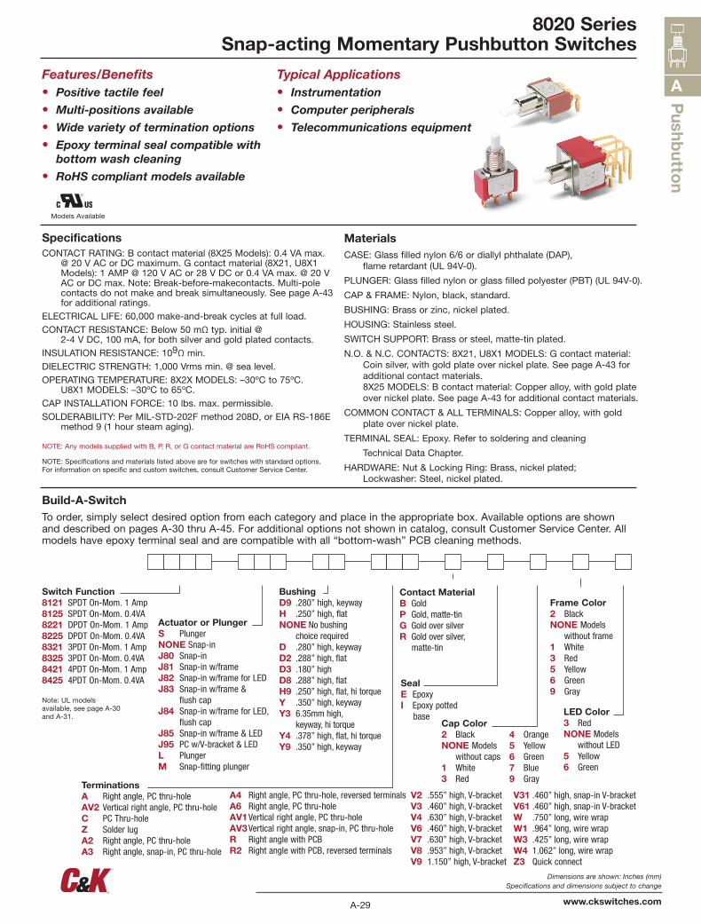
8020 SeriesSnap-acting Momentary Pushbutton Switches
Features/Benefits• Positive tactile feel
• Multi-positions available
• Wide variety of termination options
• Epoxy terminal seal compatible with bottom wash cleaning
• RoHS compliant models available
Typical Applications• Instrumentation
• Computer peripherals
• Telecommunications equipment
SpecificationsCONTACT RATING: B contact material (8X25 Models): 0.4 VA max.
@ 20 V AC or DC maximum. G contact material (8X21, U8X1 Models): 1 AMP @ 120 V AC or 28 V DC or 0.4 VA max. @ 20 V AC or DC max. Note: Break-before-makecontacts. Multi-pole contacts do not make and break simultaneously. See page A-43 for additional ratings.
ELECTRICAL LIFE: 60,000 make-and-break cycles at full load.CONTACT RESISTANCE: Below 50 mΩ typ. initial @
2-4 V DC, 100 mA, for both silver and gold plated contacts.INSULATION RESISTANCE: 109Ω min.DIELECTRIC STRENGTH: 1,000 Vrms min. @ sea level.OPERATING TEMPERATURE: 8X2X MODELS: –30ºC to 75ºC.
U8X1 MODELS: –30ºC to 65ºC.CAP INSTALLATION FORCE: 10 lbs. max. permissible.SOLDERABILITY: Per MIL-STD-202F method 208D, or EIA RS-186E
method 9 (1 hour steam aging).
NOTE: Any models supplied with B, P, R, or G contact material are RoHS compliant.
NOTE: Specifications and materials listed above are for switches with standard options. For information on specific and custom switches, consult Customer Service Center.
MaterialsCASE: Glass filled nylon 6/6 or diallyl phthalate (DAP),
flame retardant (UL 94V-0).
PLUNGER: Glass filled nylon or glass filled polyester (PBT) (UL 94V-0).
CAP & FRAME: Nylon, black, standard.
BUSHING: Brass or zinc, nickel plated.
HOUSING: Stainless steel.
SWITCH SUPPORT: Brass or steel, matte-tin plated.
N.O. & N.C. CONTACTS: 8X21, U8X1 MODELS: G contact material: Coin silver, with gold plate over nickel plate. See page A-43 for additional contact materials. 8X25 MODELS: B contact material: Copper alloy, with gold plate over nickel plate. See page A-43 for additional contact materials.
COMMON CONTACT & ALL TERMINALS: Copper alloy, with gold plate over nickel plate.
TERMINAL SEAL: Epoxy. Refer to soldering and cleaning
Technical Data Chapter.
HARDWARE: Nut & Locking Ring: Brass, nickel plated; Lockwasher: Steel, nickel plated.
Build-A-SwitchTo order, simply select desired option from each category and place in the appropriate box. Available options are shown and described on pages A-30 thru A-45. For additional options not shown in catalog, consult Customer Service Center. All models have epoxy terminal seal and are compatible with all “bottom-wash” PCB cleaning methods.
Switch Function8121 SPDT On-Mom. 1 Amp8125 SPDT On-Mom. 0.4VA8221 DPDT On-Mom. 1 Amp8225 DPDT On-Mom. 0.4VA8321 3PDT On-Mom. 1 Amp8325 3PDT On-Mom. 0.4VA8421 4PDT On-Mom. 1 Amp8425 4PDT On-Mom. 0.4VA
Note: UL models available, see page A-30 and A-31.
Actuator or PlungerS PlungerNONE Snap-inJ80 Snap-inJ81 Snap-in w/frameJ82 Snap-in w/frame for LEDJ83 Snap-in w/frame &
flush capJ84 Snap-in w/frame for LED,
flush capJ85 Snap-in w/frame & LEDJ95 PC w/V-bracket & LEDL PlungerM Snap-fitting plunger
BushingD9 .280” high, keywayH .250” high, flatNONE No bushing choice requiredD .280” high, keywayD2 .288” high, flatD3 .180” highD8 .288” high, flatH9 .250” high, flat, hi torqueY .350” high, keywayY3 6.35mm high, keyway, hi torqueY4 .378” high, flat, hi torqueY9 .350” high, keyway
Contact MaterialB GoldP Gold, matte-tinG Gold over silverR Gold over silver, matte-tin
SealE EpoxyI Epoxy potted base
Cap Color2 BlackNONE Models without caps1 White3 Red
4 Orange5 Yellow6 Green7 Blue9 Gray
Frame Color2 BlackNONE Models without frame1 White3 Red5 Yellow6 Green9 Gray
LED Color3 RedNONE Models without LED5 Yellow6 Green
TerminationsA Right angle, PC thru-holeAV2 Vertical right angle, PC thru-holeC PC Thru-holeZ Solder lugA2 Right angle, PC thru-holeA3 Right angle, snap-in, PC thru-hole
A4 Right angle, PC thru-hole, reversed terminalsA6 Right angle, PC thru-holeAV1 Vertical right angle, PC thru-holeAV3 Vertical right angle, snap-in, PC thru-holeR Right angle with PCBR2 Right angle with PCB, reversed terminals
V2 .555” high, V-bracketV3 .460” high, V-bracketV4 .630” high, V-bracketV6 .460” high, V-bracketV7 .630” high, V-bracketV8 .953” high, V-bracketV9 1.150” high, V-bracket
V31 .460” high, snap-in V-bracketV61 .460” high, snap-in V-bracketW .750” long, wire wrapW1 .964” long, wire wrapW3 .425” long, wire wrapW4 1.062” long, wire wrapZ3 Quick connect
Models Available
A-30
Dimensions are shown: Inches (mm) Specifications and dimensions subject to change
www.ckswitches.com
A
Pus
hbutton
Third AngleProjection
8020 SeriesSnap-acting Momentary Pushbutton Switches
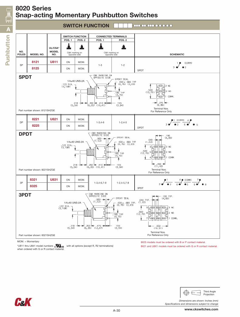
SWITCH FUNCTION
MOM. = Momentary
*U811 thru U841 model numbers with all options (except R, R2 terminations) when ordered with G or R contact material.
8X25 models must be ordered with B or P contact material.
8X21 and U8X1 models must be ordered with G or R contact material.
3PDT
1-2,4-5,7-81-3,4-6,7-9MOM.
MOM.
ON
ON
U8318321
83253P
DPDT
1-2,4-51-3,4-6MOM.
MOM.
ON
ON
U8218221
8225DP
SPDT
1-21-3MOM.
MOM.
ON
ON
U8118121
8125SP
SCHEMATIC
CONNECTED TERMINALS
POS. 1 POS. 2
SWITCH FUNCTION
POS. 1 POS. 2
UL/CSA*
MODELNO.MODEL NO.
NO.POLES
SPDT
DPDT
3PDT
Terminal Nos.For Reference Only
Terminal Nos.For Reference Only
Part number shown: 8121SHZGE
Part number shown: 8221SHZGE
Terminal Nos.For Reference OnlyPart number shown: 8321SHZGE
C&K marking onopposite side
C&K marking onopposite side

A-31
Dimensions are shown: Inches (mm) Specifications and dimensions subject to change
www.ckswitches.com
Pushb
utton
A
OPTION CODE CAP AND FRAME COLOR
2 BLACK
NONE No Frame Color (J80 option)
1 WHITE
3 RED
4 ORANGE
5 YELLOW
6 GREEN
7 BLUE
9 GRAY
Third AngleProjection
8020 SeriesSnap-acting Momentary Pushbutton Switches
SWITCH FUNCTION
ACTUATOR—SNAP-IN FRONT MOUNT
**
PANEL MOUNTING
**
PANEL MOUNTING
MOM. = Momentary
* U811 thru U841 model numbers with all options (except R, R2 terminations) when ordered with G or R contact material.
Other colors available, consult Customer Service Center. Cap and Frame Finish: matte.
NOTE: Caps and frames available separately, see pages A-44 and A-45.
NOTE: No frame color choice required.
** Increase this dim. to .620/.625 (15,75/15,88) for .091/.125 (2,31/3,18) thk. panels.
NOTE: Available with C, W-W4, Z or Z3 terminations and SPDT and DPDT models only.
** Increase this dim. to .620/.625 (15,75/15,88) for .091/.125 (2,31/3,18) thk. panels.
8X25 models must be ordered with B or P contact material.
8X21 and U8X1 models must be ordered with G or R contact material.
J80 SNAP-IN
J81 SNAP-IN WITH FRAME
ACTUATOR OR PLUNGER
CAP COLOR
FRAME COLOR
4PDT
1-2,4-5,7-8,10-111-3,4-6,7-9,10-12MOM.
MOM.
ON
ON
U8418421
84254P
SCHEMATIC
CONNECTED TERMINALS
POS. 1 POS. 2
SWITCH FUNCTION
POS. 1 POS. 2
UL/CSA*
MODEL NO.MODEL NO.
NO.POLES
4PDT
Terminal Nos.For Reference OnlyPart number shown: 8421SHZGE
C&K marking onopposite side
C&K marking onopposite side

A-32
Dimensions are shown: Inches (mm) Specifications and dimensions subject to change
www.ckswitches.com
A
Pus
hbutton
OPTION CODE
CAP AND FRAME COLOR
2 BLACK
1 WHITE
3 RED
4 ORANGE
5 YELLOW
6 GREEN
7 BLUE
9 GRAY Third AngleProjection
8020 SeriesSnap-acting Momentary Pushbutton Switches
ACTUATOR—SNAP-IN FRONT MOUNT
**
PANEL MOUNTING
J83 SNAP-IN WITH FRAME AND FLUSH CAP
LED not included.
For LED information, see page A-45.
LED not included.
For LED information, see page A-45.
J84 SNAP-IN WITH FRAME FOR LED, FLUSH CAP
J82 SNAP-IN WITH FRAME FOR LED
Other colors available, consult Customer Service Center. Cap and Frame Finish: matte.
Available with C, W-W4, Z or Z3 terminations and SPDT and DPDT models only.
NOTE: Caps and frames available separately, see pages A-44 and A-45.
ACTUATOR OR PLUNGER
CAP COLOR
FRAME COLOR
A-33
Dimensions are shown: Inches (mm) Specifications and dimensions subject to change
www.ckswitches.com
Pushb
utton
A
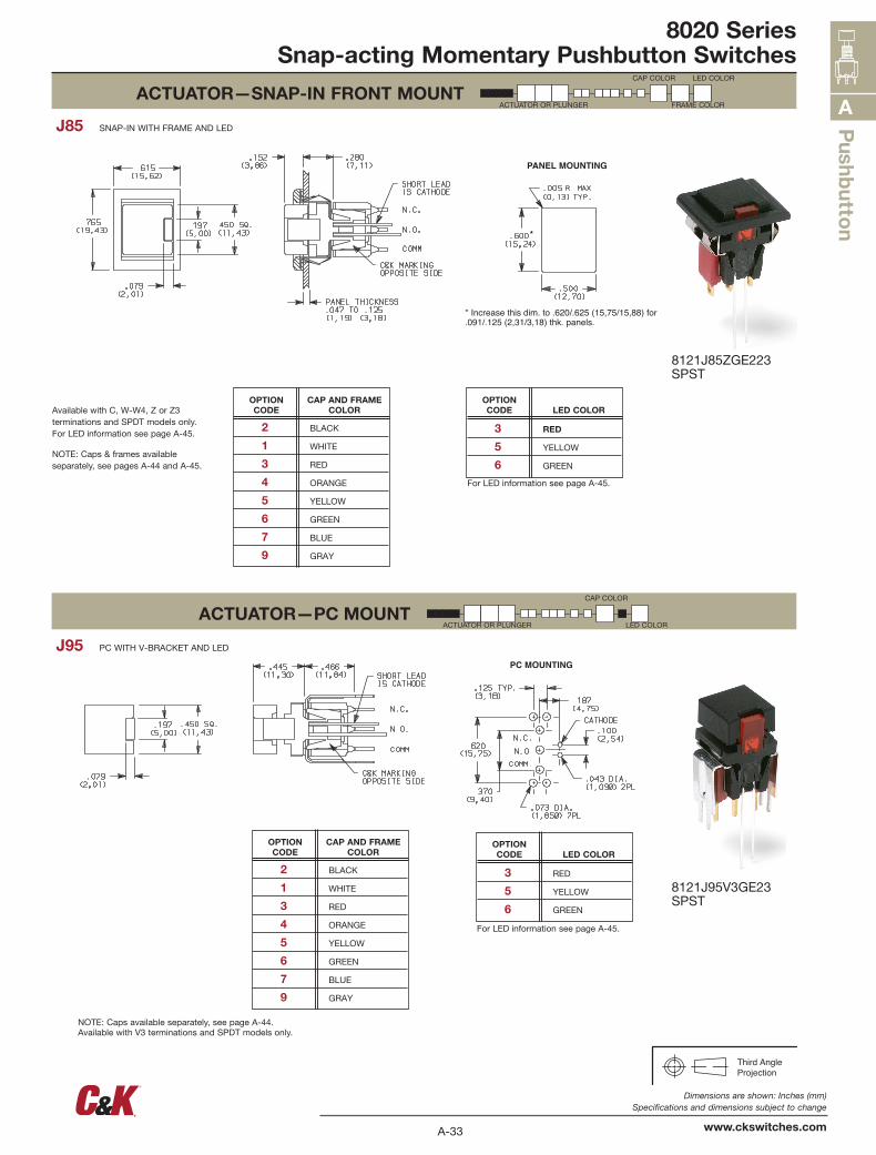
OPTION CODE
CAP AND FRAME COLOR
2 BLACK
1 WHITE
3 RED
4 ORANGE
5 YELLOW
6 GREEN
7 BLUE
9 GRAY
OPTION CODE LED COLOR
3 RED
5 YELLOW
6 GREEN
OPTION CODE
CAP AND FRAME COLOR
2 BLACK
1 WHITE
3 RED
4 ORANGE
5 YELLOW
6 GREEN
7 BLUE
9 GRAY
OPTION CODE LED COLOR
3 RED
5 YELLOW
6 GREEN
Third AngleProjection
8020 SeriesSnap-acting Momentary Pushbutton Switches
ACTUATOR—SNAP-IN FRONT MOUNT
ACTUATOR—PC MOUNT
*
* Increase this dim. to .620/.625 (15,75/15,88) for.091/.125 (2,31/3,18) thk. panels.
PANEL MOUNTING
PC MOUNTING
J85 SNAP-IN WITH FRAME AND LED
J95 PC WITH V-BRACKET AND LED
ACTUATOR OR PLUNGER
CAP COLOR LED COLOR
FRAME COLOR
ACTUATOR OR PLUNGER
CAP COLOR
LED COLOR
Available with C, W-W4, Z or Z3 terminations and SPDT models only. For LED information see page A-45.
NOTE: Caps & frames available separately, see pages A-44 and A-45.
For LED information see page A-45.
NOTE: Caps available separately, see page A-44. Available with V3 terminations and SPDT models only.
For LED information see page A-45.
8121J85ZGE223SPST
8121J95V3GE23SPST
A-34
Dimensions are shown: Inches (mm) Specifications and dimensions subject to change
www.ckswitches.com
A
Pus
hbutton
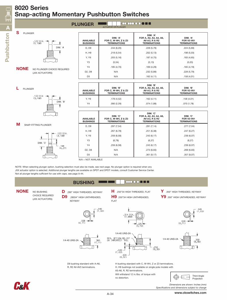
AVAILABLE BUSHINGS
DIM. ‘A’ FOR C, W-W4, Z & Z3
TERMINATIONS
DIM. ‘A’ FOR A, A2, A3, A4, A6,
AV-A3, R & R2 TERMINATIONS
DIM. ‘A’ FOR V3-V61
TERMINATIONS
D, D9 .244 (6,20) .228 (5,79) .224 (5,69)
H, H9 .218 (5,54) .202 (5,13) .198 (5,03)
Y, Y9 .203 (5,16) .187 (4,75) .183 (4,65)
Y3 (5,54) (5,13) (5,03)
Y4 .185 (4,70) .169 (4,29) .165 (4,19)
D2, D8 N/A .232 (5,89) .228 (5,79)
D3 N/A .162 (4,11) .158 (4,01)
AVAILABLE BUSHINGS
DIM. ‘C’ FOR C, W-W4, Z & Z3
TERMINATIONS
DIM. ‘C’ FOR A, A2, A3, A4, A6,
AV-A3, R & R2 TERMINATIONS
DIM. ‘C’ FOR V3-V61
TERMINATIONS
D, D9 .297 (7,54) .281 (7,14) .277 (7,04)
H, H9 .267 (6,78) .251 (6,38) .247 (6,27)
Y, Y9 .259 (6,58) .243 (6,17) .239 (6,07)
Y3 (6,78) (6,37) (6,27)
Y4 .259 (6,58) .243 (6,17) .239 (6,07)
D2, D8 N/A .273 (6,93) .269 (6,83)
D3 N/A .361 (9,17) .357 (9,07)
AVAILABLE BUSHINGS
DIM. ‘B’ FOR C, W-W4, Z & Z3
TERMINATIONS
DIM. ‘B’ FOR A, A2, A3, A4, A6,
AV-A3, R & R2 TERMINATIONS
DIM. ‘B’ FOR V3-V61
TERMINATIONS
Y, Y9 .178 (4,52) .162 (4,11) .158 (4,01)
Y4 .090 (2,29) .074 (1,88) .070 (1,78)
Third AngleProjection
8020 SeriesSnap-acting Momentary Pushbutton Switches
PLUNGER
BUSHING
1/4-40 UNS-2A
NONE NO BUSHING
CHOICE REQUIRED
(JXX ACTUATORS)Y9 .350” HIGH UNTHREADED, KEYWAYH9 .250”34 HIGH UNTHREADED,
FLAT
H .250”34 HIGH THREADED, FLAT Y .350” HIGH THREADED, KEYWAY
D9 .28034” HIGH UNTHREADED,
KEYWAY
D .280” HIGH THREADED, KEYWAY
M SNAP-FITTING PLUNGER
L PLUNGER
NONE NO PLUNGER CHOICE REQUIRED
(JXX ACTUATORS)
S PLUNGER
ACTUATOR OR PLUNGER
NOTE: When selecting plunger option, bushing selection must also be made, see next page. No plunger option is required when any
JXX actuator option is selected. Additional plunger lengths are available on SPDT and DPDT models, consult Customer Service Center.
Not all plunger lengths sufficient for use with caps, see page A-44.
H bushing standard with C, W-W4, Z or Z3 terminations.
H, H9 bushings not available on single pole models with
A3-A6, R, R2 terminations.
Will withstand 12 in./lbs. of torque with
no distortion.
D9 bushing standard with A-A6,
R, R2 AV-AV3 terminations.
N/A = NOT AVAILABLE
A-35
Dimensions are shown: Inches (mm) Specifications and dimensions subject to change
www.ckswitches.com
Pushb
utton
A
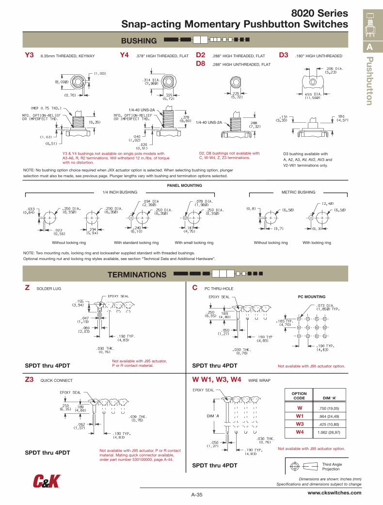
OPTION CODE DIM ‘A’
W .750 (19,05)
W1 .964 (24,49)
W3 .425 (10,80)
W4 1.062 (26,97)
Third AngleProjection
8020 SeriesSnap-acting Momentary Pushbutton Switches
BUSHING
TERMINATIONS
1/4-40 UNS-2A
PC MOUNTING
DIM `A'
W W1, W3, W4 WIRE WRAPZ3 QUICK CONNECT
C PC THRU-HOLEZ SOLDER LUG
D3 .180” HIGH UNTHREADED
D8 .288” HIGH UNTHREADED, FLAT
D2 .288” HIGH THREADED, FLATY4 .378” HIGH THREADED, FLATY3 6.35mm THREADED, KEYWAY
SPDT thru 4PDT
SPDT thru 4PDT
SPDT thru 4PDTSPDT thru 4PDT
Not available with J95 actuator, P or R contact material. Mating quick connector available, order part number 530100000, page A-44.
Not available with J95 actuator option.
Not available with J95 actuator option.Not available with J95 actuator, P or R contact material.
NOTE: No bushing option choice required when JXX actuator option is selected. When selecting bushing option, plunger
selection must also be made, see previous page. Plunger lengths vary with bushing and termination options selected.
NOTE: Two mounting nuts, locking ring and lockwasher supplied standard with threaded bushings.
Optional mounting nut and locking ring styles available, see section “Technical Data and Additional Hardware”.
Y3 & Y4 bushings not available on single pole models withA3-A6, R, R2 terminations. Will withstand 12 in./lbs. of torquewith no distortion.
D2, D8 bushings not available withC, W-W4, Z, Z3 terminations.
D3 bushing available with
A, A2, A3, AV, AV2, AV3 and
V2-V61 terminations only.
A-36
Dimensions are shown: Inches (mm) Specifications and dimensions subject to change
www.ckswitches.com
A
Pus
hbutton
Third AngleProjection
8020 SeriesSnap-acting Momentary Pushbutton Switches
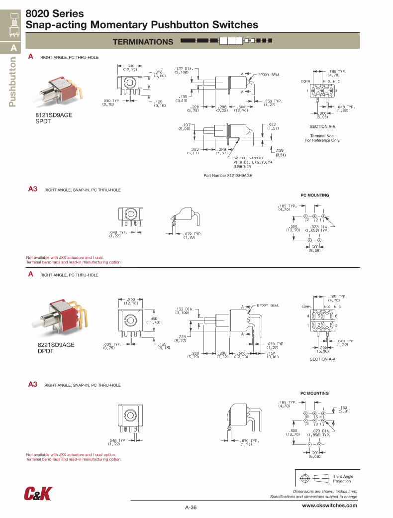
TERMINATIONS
PC MOUNTING
PC MOUNTING
SECTION A-A
.138(3,51)
A3 RIGHT ANGLE, SNAP-IN, PC THRU-HOLE
A RIGHT ANGLE, PC THRU-HOLE
A RIGHT ANGLE, PC THRU-HOLE
A3 RIGHT ANGLE, SNAP-IN, PC THRU-HOLE
8121SD9AGESPDT
8221SD9AGEDPDT
Not available with JXX actuators and I seal.Terminal bend radii and lead-in manufacturing option.
Not available with JXX actuators and I seal option.Terminal bend radii and lead-in manufacturing option.
A-37
Dimensions are shown: Inches (mm) Specifications and dimensions subject to change
www.ckswitches.com
Pushb
utton
A
Third AngleProjection
8020 SeriesSnap-acting Momentary Pushbutton Switches
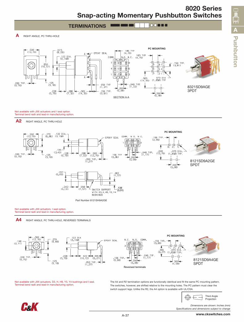
TERMINATIONS
SECTION A-A
PC MOUNTING
8321SD9AGE3PDT
8121SD9A2GESPDT
8121SD9A4GESPDT
A4 RIGHT ANGLE, PC THRU-HOLE, REVERSED TERMINALS
A2 RIGHT ANGLE, PC THRU-HOLE
A RIGHT ANGLE, PC THRU-HOLE
Not available with JXX actuators and I seal option.Terminal bend radii and lead-in manufacturing option.
Not available with JXX actuators, I seal option.Terminal bend radii and lead-in manufacturing option.
Not available with JXX actuators, D3, H, H9, Y3, Y4 bushings and I seal.Terminal bend radii and lead-in manufacturing option.
The A4 and R2 termination options are functionally identical and fit the same PC mounting pattern.
The switches, however, are shifted relative to the mounting holes. The PC pattern must clear the
switch support legs. Unlike the R2, the A4 option is available with UL/CSA.
PC MOUNTING
A-38
Dimensions are shown: Inches (mm) Specifications and dimensions subject to change
www.ckswitches.com
A
Pus
hbutton
Third AngleProjection
8020 SeriesSnap-acting Momentary Pushbutton Switches
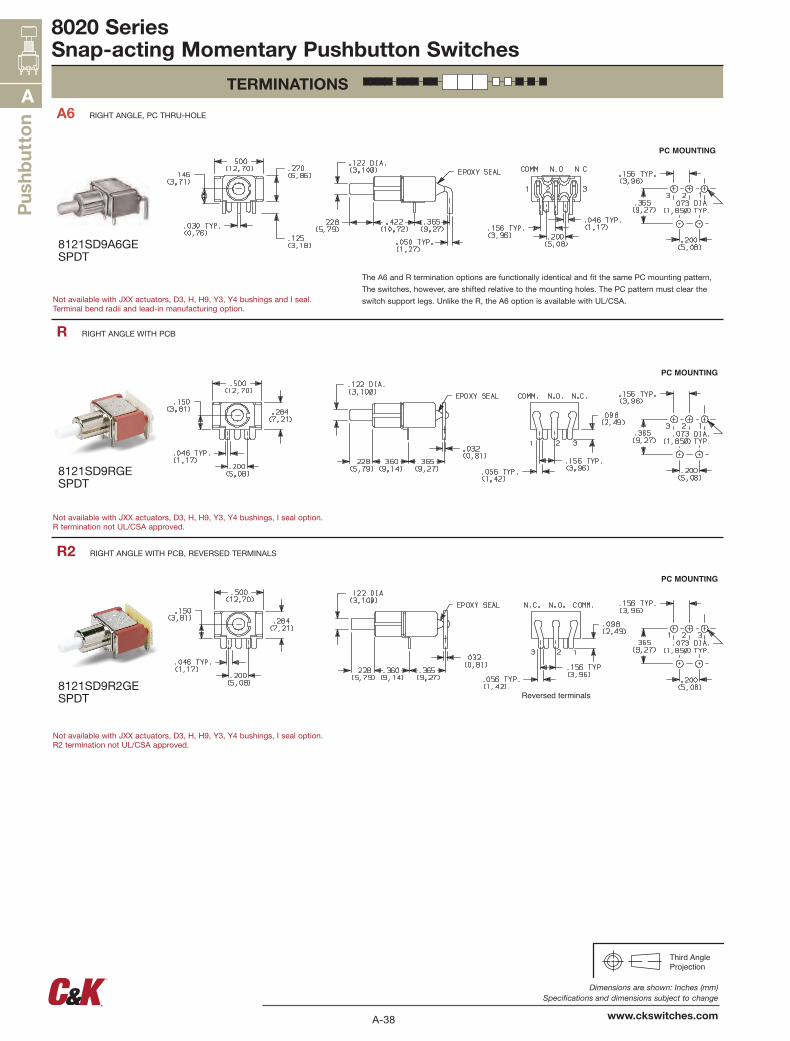
TERMINATIONS
PC MOUNTING
Reversed terminals
PC MOUNTING
PC MOUNTING
A6 RIGHT ANGLE, PC THRU-HOLE
R2 RIGHT ANGLE WITH PCB, REVERSED TERMINALS
R RIGHT ANGLE WITH PCB
Not available with JXX actuators, D3, H, H9, Y3, Y4 bushings and I seal.Terminal bend radii and lead-in manufacturing option.
Not available with JXX actuators, D3, H, H9, Y3, Y4 bushings, I seal option.R termination not UL/CSA approved.
Not available with JXX actuators, D3, H, H9, Y3, Y4 bushings, I seal option.R2 termination not UL/CSA approved.
The A6 and R termination options are functionally identical and fit the same PC mounting pattern,
The switches, however, are shifted relative to the mounting holes. The PC pattern must clear the
switch support legs. Unlike the R, the A6 option is available with UL/CSA.
8121SD9A6GESPDT
8121SD9RGESPDT
8121SD9R2GESPDT
A-39
Dimensions are shown: Inches (mm) Specifications and dimensions subject to change
www.ckswitches.com
Pushb
utton
A
Third AngleProjection
8020 SeriesSnap-acting Momentary Pushbutton Switches
TERMINATIONS
.15 (3,8)
.33 TYP.(8,4)
PC MOUNTING
PC MOUNTING
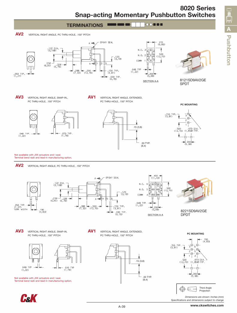
AV2 VERTICAL RIGHT ANGLE, PC THRU-HOLE, .150” PITCH
AV1 VERTICAL RIGHT ANGLE, EXTENDED,
PC THRU-HOLE, .150” PITCH
AV3 VERTICAL RIGHT ANGLE, SNAP-IN,,
PC THRU-HOLE, .150” PITCH
AV1 VERTICAL RIGHT ANGLE, EXTENDED,
PC THRU-HOLE, .150” PITCH
AV3 VERTICAL RIGHT ANGLE, SNAP-IN,
PC THRU-HOLE, .150” PITCH
AV2 VERTICAL RIGHT ANGLE, PC THRU-HOLE, .150” PITCH
8121SD9AV2GESPDT
8221SD9AV2GEDPDT
Not available with JXX actuators and I seal.Terminal bend radii and lead-in manufacturing option.
Not available with JXX actuators and I seal.Terminal bend radii and lead-in manufacturing option.
A-40
Dimensions are shown: Inches (mm) Specifications and dimensions subject to change
www.ckswitches.com
A
Pus
hbutton
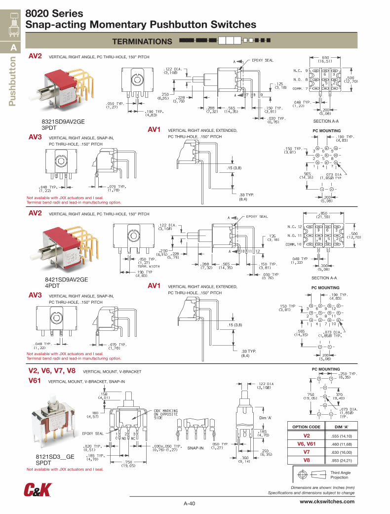
OPTION CODE DIM ‘A’
V2 .555 (14,10)
V6, V61 .460 (11,68)
V7 .630 (16,00)
V8 .953 (24,21)
Third AngleProjection
8020 SeriesSnap-acting Momentary Pushbutton Switches
TERMINATIONS
.15 (3,8)
.33 TYP.(8,4)
PC MOUNTING
PC MOUNTING
PC MOUNTING
8321SD9AV2GE3PDT
8421SD9AV2GE4PDT
8121SD3__GESPDT
AV2 VERTICAL RIGHT ANGLE, PC THRU-HOLE, 150” PITCH
AV1 VERTICAL RIGHT ANGLE, EXTENDED,
PC THRU-HOLE, .150” PITCHAV3 VERTICAL RIGHT ANGLE, SNAP-IN,
PC THRU-HOLE, .150” PITCH
V2, V6, V7, V8 VERTICAL MOUNT, V-BRACKET
V61 VERTICAL MOUNT, V-BRACKET, SNAP-IN
AV1 VERTICAL RIGHT ANGLE, EXTENDED,
PC THRU-HOLE, .150” PITCHAV3 VERTICAL RIGHT ANGLE, SNAP-IN,
PC THRU-HOLE, .150” PITCH
AV2 VERTICAL RIGHT ANGLE, PC THRU-HOLE, 150” PITCH
Not available with JXX actuators and I seal.Terminal bend radii and lead-in manufacturing option.
Not available with JXX actuators and I seal.Terminal bend radii and lead-in manufacturing option.
Not available with JXX actuators and I seal.
A-41
Dimensions are shown: Inches (mm) Specifications and dimensions subject to change
www.ckswitches.com
Pushb
utton
A
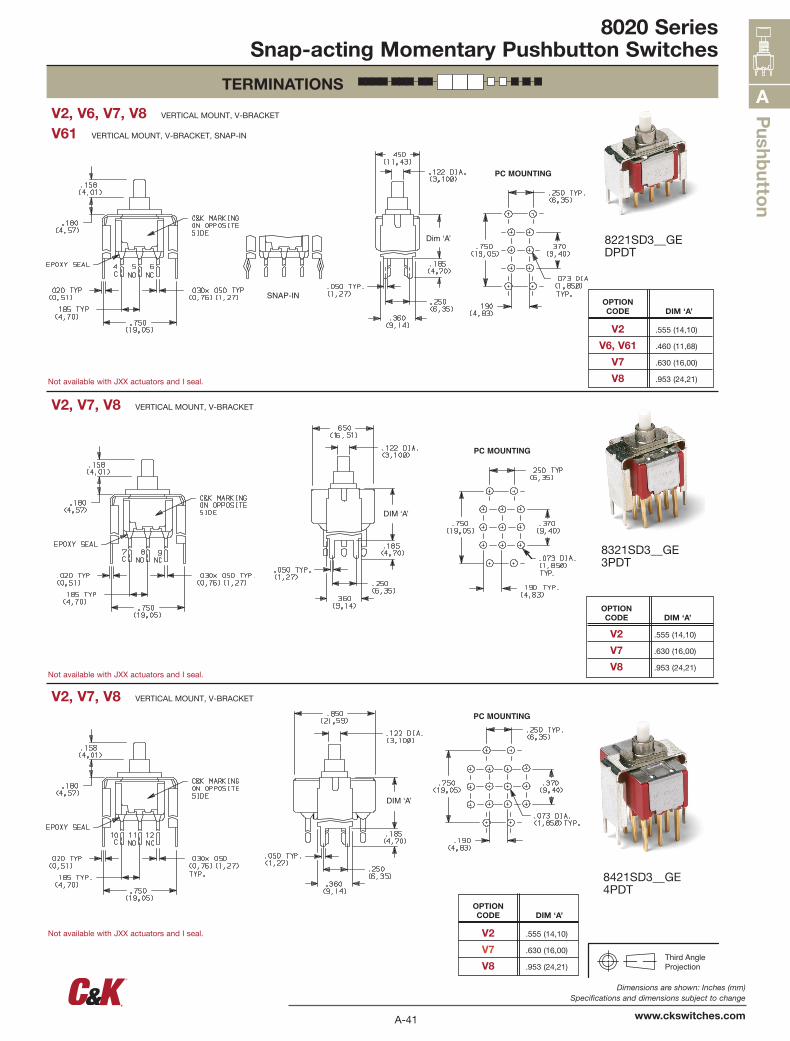
OPTION CODE DIM ‘A’
V2 .555 (14,10)
V7 .630 (16,00)
V8 .953 (24,21)
OPTION CODE DIM ‘A’
V2 .555 (14,10)
V7 .630 (16,00)
V8 .953 (24,21)Third AngleProjection
8020 SeriesSnap-acting Momentary Pushbutton Switches
TERMINATIONS
PC MOUNTING
PC MOUNTING
PC MOUNTING
V61 VERTICAL MOUNT, V-BRACKET, SNAP-IN
V2, V6, V7, V8 VERTICAL MOUNT, V-BRACKET
V2, V7, V8 VERTICAL MOUNT, V-BRACKET
V2, V7, V8 VERTICAL MOUNT, V-BRACKET
8221SD3__GEDPDT
8321SD3__GE3PDT
8421SD3__GE4PDT
Not available with JXX actuators and I seal.
Not available with JXX actuators and I seal.
Not available with JXX actuators and I seal.
OPTION CODE DIM ‘A’
V2 .555 (14,10)
V6, V61 .460 (11,68)
V7 .630 (16,00)
V8 .953 (24,21)
A-42
Dimensions are shown: Inches (mm) Specifications and dimensions subject to change
www.ckswitches.com
A
Pus
hbutton
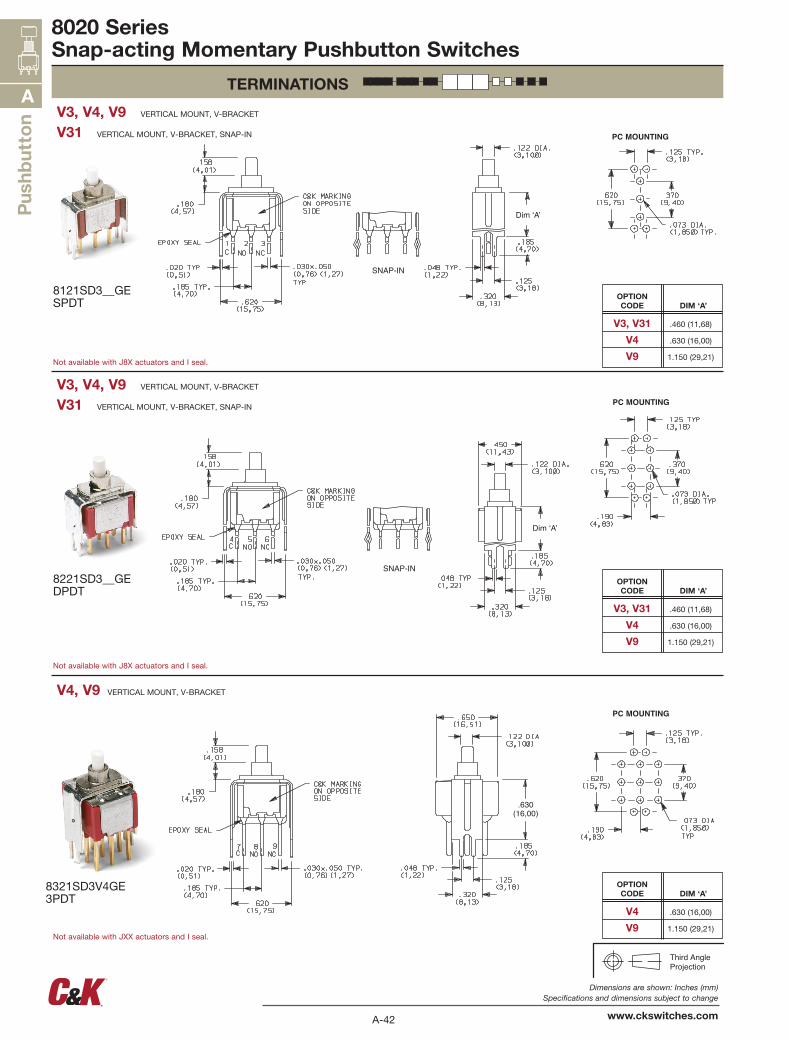
OPTION CODE DIM ‘A’
V3, V31 .460 (11,68)
V4 .630 (16,00)
V9 1.150 (29,21)
OPTION CODE DIM ‘A’
V3, V31 .460 (11,68)
V4 .630 (16,00)
V9 1.150 (29,21)
OPTION CODE DIM ‘A’
V4 .630 (16,00)
V9 1.150 (29,21)
Third AngleProjection
8020 SeriesSnap-acting Momentary Pushbutton Switches
TERMINATIONS
PC MOUNTING
PC MOUNTING
.630(16,00)
PC MOUNTING
V31 VERTICAL MOUNT, V-BRACKET, SNAP-IN
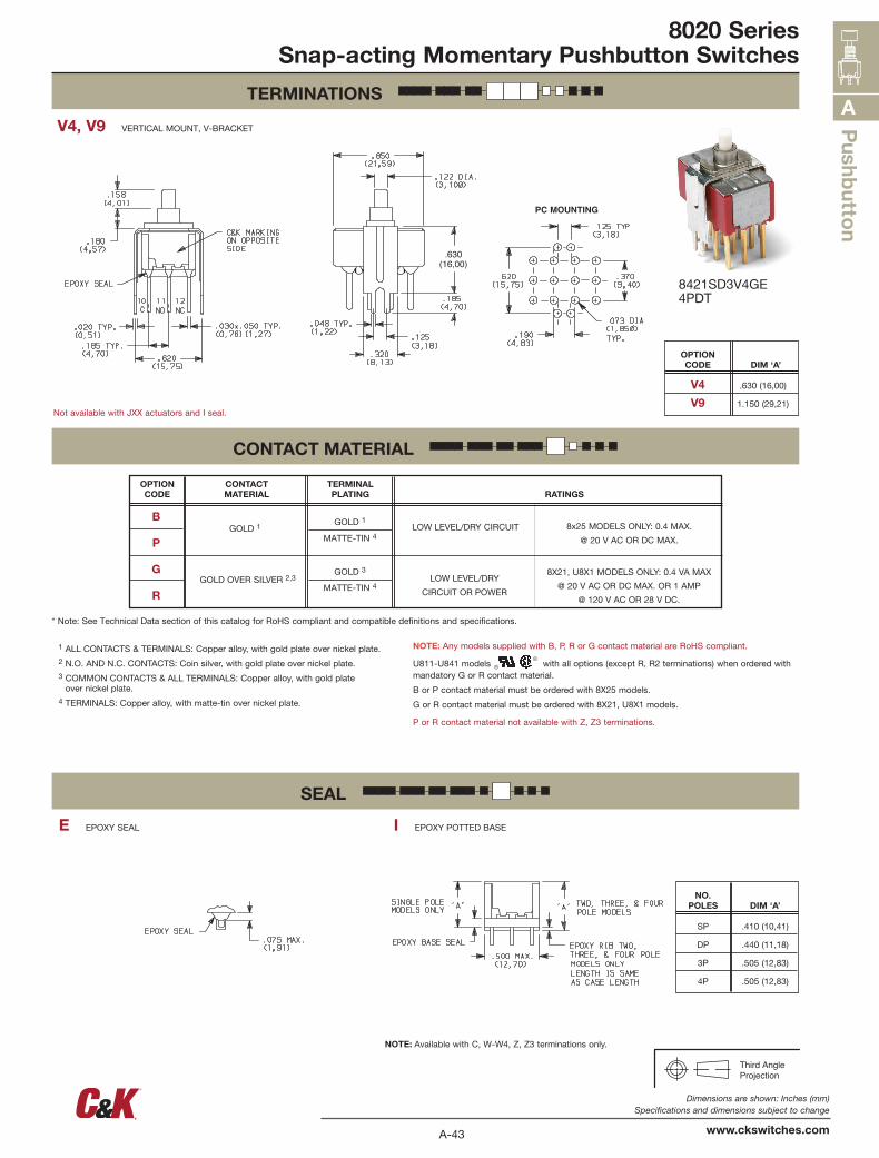
V3, V4, V9 VERTICAL MOUNT, V-BRACKET
V4, V9 VERTICAL MOUNT, V-BRACKET
V31 VERTICAL MOUNT, V-BRACKET, SNAP-IN
V3, V4, V9 VERTICAL MOUNT, V-BRACKET
Not available with J8X actuators and I seal.
Not available with J8X actuators and I seal.
Not available with JXX actuators and I seal.
8121SD3__GESPDT
8221SD3__GEDPDT
8321SD3V4GE3PDT
A-43
Dimensions are shown: Inches (mm) Specifications and dimensions subject to change
www.ckswitches.com
Pushb
utton
A
OPTION CODE DIM ‘A’
V4 .630 (16,00)
V9 1.150 (29,21)
NO. POLES DIM ‘A’
SP .410 (10,41)
DP .440 (11,18)
3P .505 (12,83)
4P .505 (12,83)
Third AngleProjection
8020 SeriesSnap-acting Momentary Pushbutton Switches
TERMINATIONS
CONTACT MATERIAL
SEAL
PC MOUNTING
.630(16,00)
Not available with JXX actuators and I seal.
8421SD3V4GE4PDT
V4, V9 VERTICAL MOUNT, V-BRACKET
E EPOXY SEAL I EPOXY POTTED BASE
* Note: See Technical Data section of this catalog for RoHS compliant and compatible definitions and specifications.
1 ALL CONTACTS & TERMINALS: Copper alloy, with gold plate over nickel plate.2 N.O. AND N.C. CONTACTS: Coin silver, with gold plate over nickel plate.3 COMMON CONTACTS & ALL TERMINALS: Copper alloy, with gold plate
over nickel plate.4 TERMINALS: Copper alloy, with matte-tin over nickel plate.
NOTE: Any models supplied with B, P, R or G contact material are RoHS compliant.
U811-U841 models with all options (except R, R2 terminations) when ordered with mandatory G or R contact material.
B or P contact material must be ordered with 8X25 models.
G or R contact material must be ordered with 8X21, U8X1 models.
P or R contact material not available with Z, Z3 terminations.
NOTE: Available with C, W-W4, Z, Z3 terminations only.
OPTION CODE
CONTACT MATERIAL
TERMINAL PLATING RATINGS
GOLD 1
GOLD 3
MATTE-TIN 4
GOLD 1
MATTE-TIN 4LOW LEVEL/DRY CIRCUIT
LOW LEVEL/DRY
CIRCUIT OR POWER
8x25 MODELS ONLY: 0.4 MAX.
@ 20 V AC OR DC MAX.
8X21, U8X1 MODELS ONLY: 0.4 VA MAX
@ 20 V AC OR DC MAX. OR 1 AMP
@ 120 V AC OR 28 V DC.
B
P
G
RGOLD OVER SILVER 2,3
A-44
Dimensions are shown: Inches (mm) Specifications and dimensions subject to change
www.ckswitches.com
A
Pus
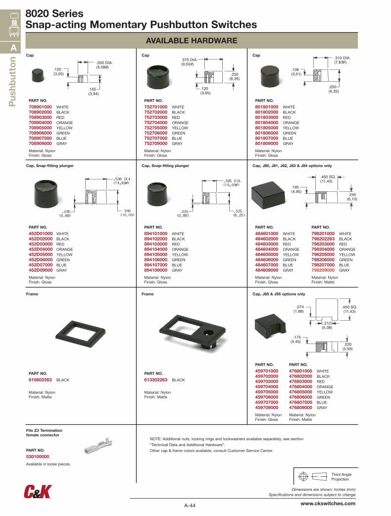
hbutton Cap
PART NO.
708901000 WHITE708902000 BLACK708903000 RED708904000 ORANGE708905000 YELLOW708906000 GREEN708907000 BLUE708909000 GRAY
Material: Nylon Finish: Gloss
Cap
PART NO.
752701000 WHITE752702000 BLACK752703000 RED752704000 ORANGE752705000 YELLOW752706000 GREEN752707000 BLUE752709000 GRAY
Material: Nylon Finish: Gloss
Cap
PART NO.
801801000 WHITE801802000 BLACK801803000 RED801804000 ORANGE801805000 YELLOW801806000 GREEN801807000 BLUE801809000 GRAY
Material: Nylon Finish: Gloss
Cap, Snap-fitting plunger
PART NO.
452D01000 WHITE452D02000 BLACK452D03000 RED452D04000 ORANGE452D05000 YELLOW452D06000 GREEN452D07000 BLUE452D09000 GRAY
Material: Nylon Finish: Gloss
Cap, Snap-fitting plunger
PART NO.
894101000 WHITE894102000 BLACK894103000 RED894104000 ORANGE894105000 YELLOW894106000 GREEN894107000 BLUE894109000 GRAY
Material: Nylon Finish: Gloss
Cap, J80, J81, J82, J83 & J84 options only
PART NO.
484601000 WHITE484602000 BLACK484603000 RED484604000 ORANGE484605000 YELLOW484606000 GREEN484607000 BLUE484609000 GRAY
Material: Nylon Finish: Gloss
Frame
PART NO.
615602263 BLACK
Material: Nylon Finish: Matte
Frame
PART NO.
613302263 BLACK
Material: Nylon Finish: Matte
Cap, J85 & J95 options only
PART NO.
459701000 459702000 459703000 459704000 459705000 459706000 459707000 459709000
Material: Nylon Finish: Gloss
Third AngleProjection
8020 SeriesSnap-acting Momentary Pushbutton Switches
AVAILABLE HARDWARE
Fits Z3 Termination female connector
PART NO.
530100000
Available in loose pieces.
PART NO.
476801000 WHITE476802000 BLACK476803000 RED476804000 ORANGE476805000 YELLOW476806000 GREEN476807000 BLUE476809000 GRAY
Material: Nylon Finish: Matte
PART NO.
798201000 WHITE798202263 BLACK798203000 RED798204000 ORANGE798205000 YELLOW798206000 GREEN798207000 BLUE798209000 GRAY
Material: Nylon Finish: Matte
NOTE: Additional nuts, locking rings and lockwashers available separately, see section
“Technical Data and Additional Hardware”.
Other cap & frame colors available, consult Customer Service Center.
A-45
Dimensions are shown: Inches (mm) Specifications and dimensions subject to change
www.ckswitches.com
Pushb
utton
A
Third AngleProjection
8020 SeriesSnap-acting Momentary Pushbutton Switches
AVAILABLE HARDWARE
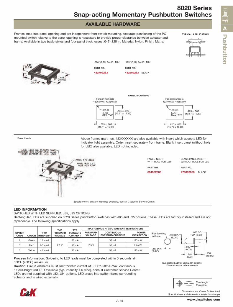
.030(0,76)
.200 DIA.(5,08˘)
.025 SQ.TYP. (0,63)
.750(19,05).340
(8,64)
.230 DIA.(5,84˘)
Flat denotescathode.
Suggested LED for J82 & J84 options.Dimensions for reference only.
TYPICAL APPLICATION
Above frames (part nos. 432XXXXXX) are also available with insert which accepts LED for indicator light assembly. Order insert separately from frame. Blank insert panel (without hole for LED) also available. LED not included.
Panel Inserts
Special colors, custom markings available, consult Customer Service Center.
PANEL INSERT WITH HOLE FOR LED
PART NO.
894902000
BLANK PANEL INSERT WITHOUT HOLE FOR LED
PART NO.
476602000 BLACK
.090” (2,29) PANEL THK.
PART NO.
432702263
.125” (3,18) PANEL THK.
PART NO.
432802263 BLACK
Frames snap into panel opening and are independent from switch mounting. Accurate positioning of the PC mounted switch relative to the panel opening is necessary to provide proper clearance between actuator and frame. Available in two basic styles and four panel thicknesses .047-.125 in. Material: Nylon. Finish: Matte.
LED INFORMATIONSWITCHES WITH LED SUPPLIED: J85, J95 OPTIONS:Rectangular LEDs are supplied on 8020 Series pushbutton switches with J85 and J95 options. These LEDs are factory installed and are not replaceable. The following specifications apply:
Process Information: Soldering to LED leads must be completed within 5 seconds at 500ºF (260ºC) maximum.Caution: Circuit elements must limit forward current of LED to 50mA max. continuous. * Extra-bright red LED available (typ. intensity 4.5 mcd), consult Customer Service Center.LEDs are not supplied with J82, J84 options. LED snaps into switch frame surrounding actuator and is wired externally.
OPTION CODE COLOR
TYP. INTENSITY
TYP. FORWARD VOLTAGE
TYP. FORWARD CURRENT
MAX RATINGS AT 25ºC AMBIENT TEMPERATURE
FORWARD CONTINUOUS POWER VOLTAGE FORWARD CURRENT DISSIPATION
6
3
5
Green
Red*
Yellow
1.0 mcd
0.5 mcd
4.0 mcd
2.1 V
20 mA
10 mA
20 mA
2.5 V
50 mA
30 mA
50 mA
125 mW
75 mW
125 mW