802.11b/g/n 300mbps wireless vdsl2 router - netoptv.de · 802.11b/g/n 300mbps wireless vdsl2 router...
TRANSCRIPT
802.11b/g/n 300Mbps Wireless VDSL2 RouterQuick Installation Guide
Werftstr. 20, 30163 Hannover Fon: +49 511 (0) 6551387-0 www.netopsie-tech.de
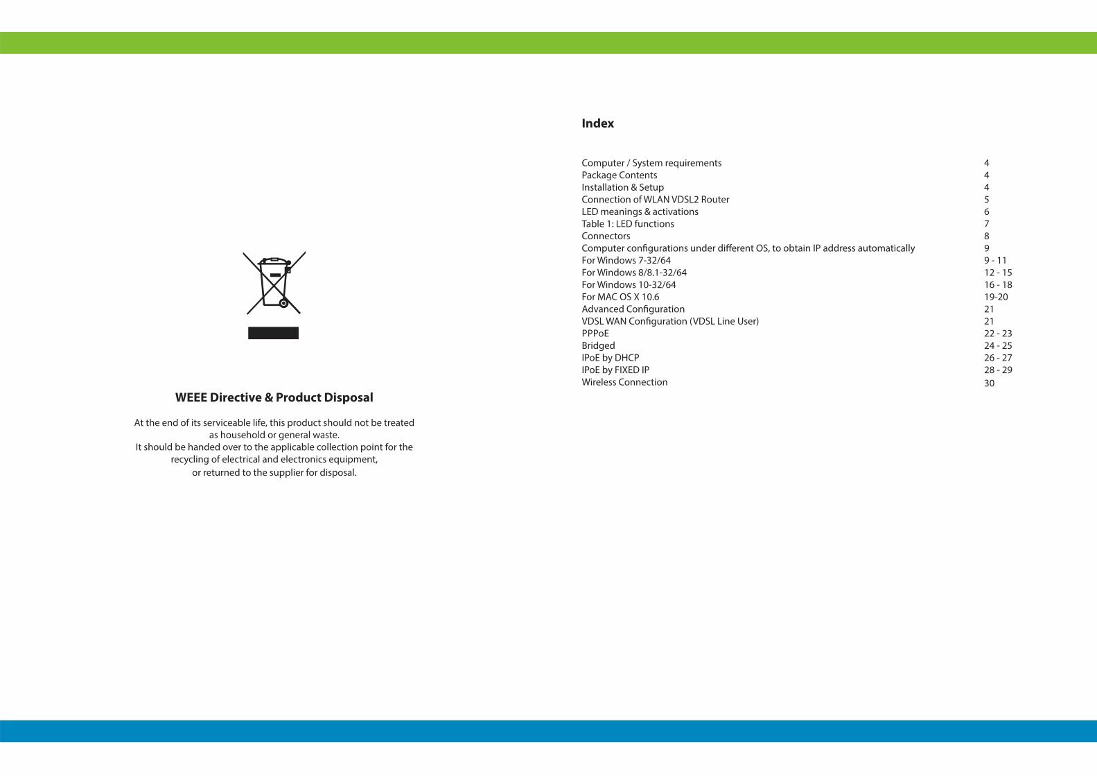
WEEE Directive & Product Disposal
At the end of its serviceable life, this product should not be treated as household or general waste.
It should be handed over to the applicable collection point for the recycling of electrical and electronics equipment,
or returned to the supplier for disposal.
Index
Computer / System requirements Package Contents Installation & Setup Connection of WLAN VDSL2 Router LED meanings & activations Table 1: LED functionsConnectors Computer configurations under different OS, to obtain IP address automatically For Windows 7-32/64 For Windows 8/8.1-32/64For Windows 10-32/64 For MAC OS X 10.6Advanced Configuration VDSL WAN Configuration (VDSL Line User) PPPoEBridgedIPoE by DHCPIPoE by FIXED IPWireless Connection
444567899 - 1112 - 1516 - 1819-20212122 - 2324 - 2526 - 2728 - 2930

4 5
COMPUTER / SYSTEM REQUIREMENTS
Windows 98SE, Windows Me, Windows 2000, Windows XP, Windows Vista, Windows 7, Windows 8 , Windows 8.1 and Windows 10
PACKAGE CONTENTS
1. 802.11n WLAN VDSL2 Router 2. Quick Installation Guide3. 1 x Telephone Cable (RJ-11)4. Ethernet Cable (RJ-45)5. Power Adaptor
INSTALLATION & SETUP
Follow each STEP carefully and only go to the next step once you have completed the previous STEP.
CONNECTION OF WLAN VDSL2 ROUTERIf you have a PSTN telephone line (normal analog line) connect the modem router as shown below
Connect the supplied RJ45 Ethernet cable from your PC's Ethernet port to any of the 4 802.11n WLAN VDSL2 Router's LAN Ports.
Connect the supplied RJ11 telephone cable from your home‘s telephone jack to the LINE port of the supplied splitter. Connect another RJ11 telephone cable to the DSL port of the splitter and connect the other end of this cable to the LINE port of your 802.11n WLAN VDSL2 Router.
Or, direct connects the supplied RJ11 telephone cable from your home’s telephone jack to the LINE port of your 802.11n WLAN VDSL2 Router, in case there is no supplied splitter.
Connect a RJ11 telephone cable to the PHONE port of the splitter and connect the other end to your telephone.
Connect the power adapter to the power inlet POWER of the 802.11n WLAN VDSL2 Router and turn the ON/OFF SWITCH switch of your 802.11n WLAN VDSL2 Router on.
1.
2.
3.
4.
6 7
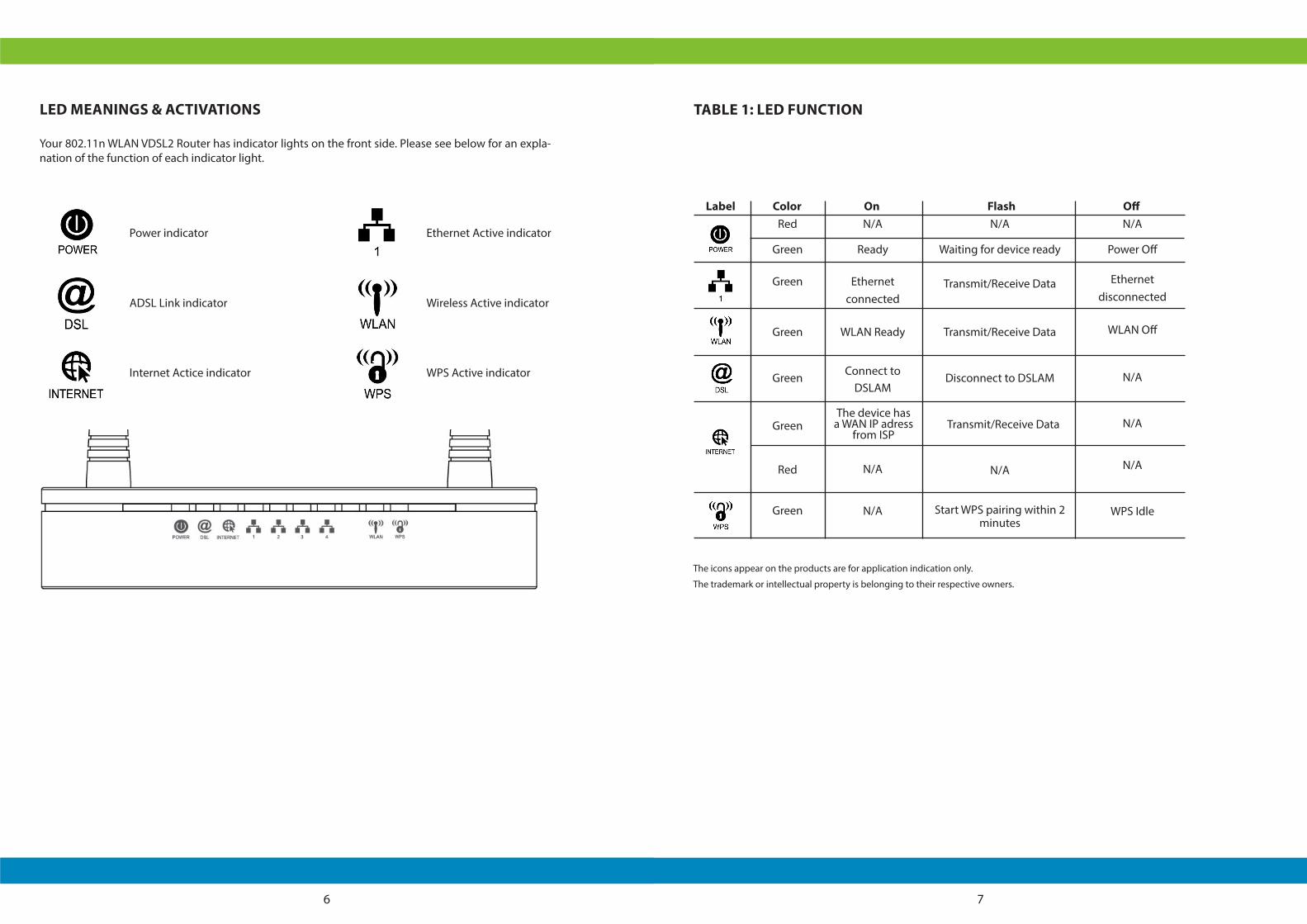
LED MEANINGS & ACTIVATIONS
Your 802.11n WLAN VDSL2 Router has indicator lights on the front side. Please see below for an expla-nation of the function of each indicator light.
Power indicator
ADSL Link indicator
Internet Actice indicator
Ethernet Active indicator
Wireless Active indicator
WPS Active indicator
Label Color On Flash OffRed
Green
Green
Green
Green
Green
Red
Green
N/A
Ready
Ethernetconnected
WLAN Ready
Connect to DSLAM
N/A
N/A
The device has a WAN IP adress
from ISP
N/A
Waiting for device ready
Transmit/Receive Data
Transmit/Receive Data
Disconnect to DSLAM
N/A
Start WPS pairing within 2 minutes
Transmit/Receive Data
N/A
Power Off
Ethernetdisconnected
WLAN Off
N/A
N/A
N/A
WPS Idle
TABLE 1: LED FUNCTION
The icons appear on the products are for application indication only.
The trademark or intellectual property is belonging to their respective owners.
8 9
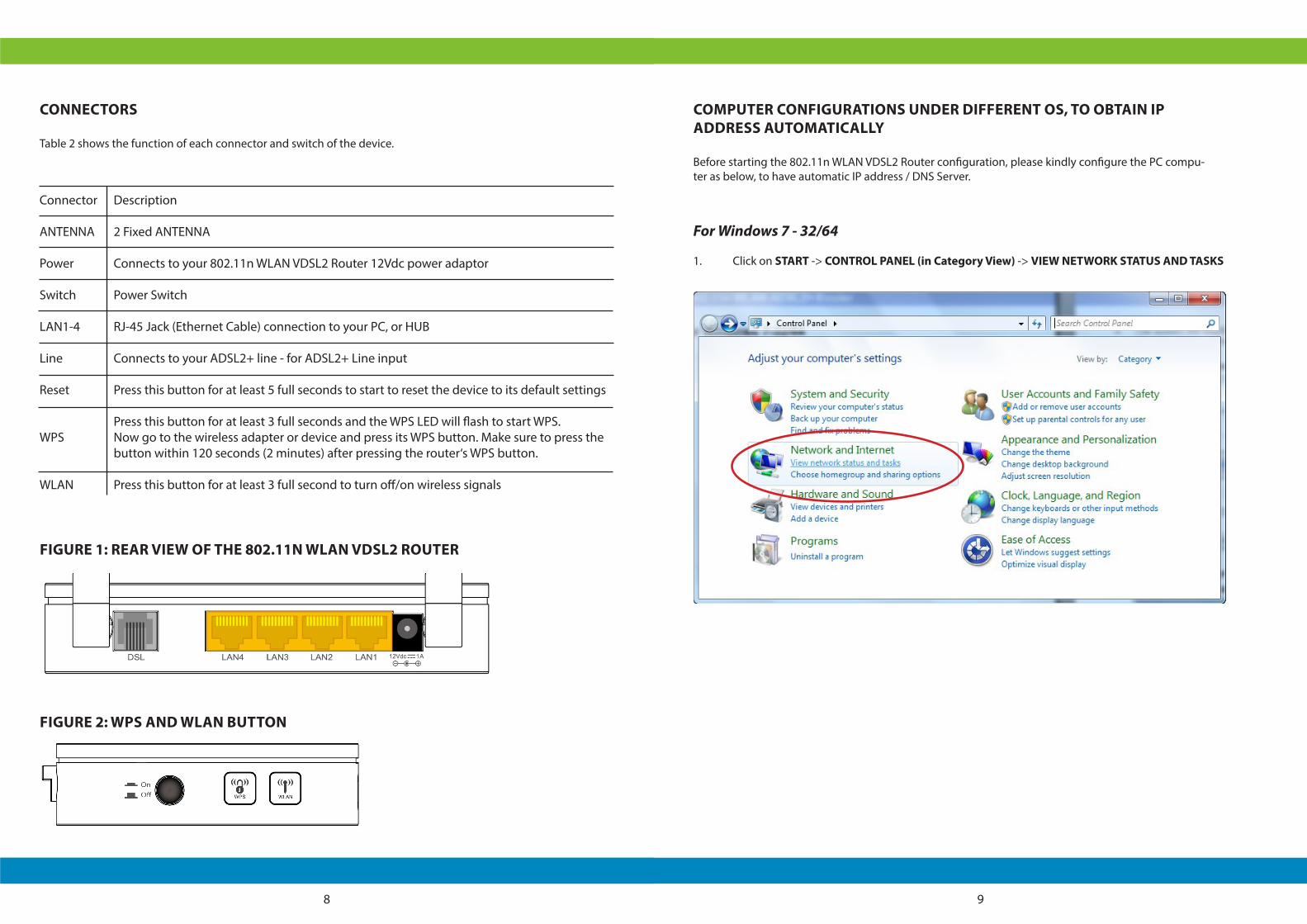
CONNECTORS
Table 2 shows the function of each connector and switch of the device.
Connector
ANTENNA
Power
Switch
LAN1-4
Line
Reset
WPS
WLAN
Description
2 Fixed ANTENNA
Connects to your 802.11n WLAN VDSL2 Router 12Vdc power adaptor
Power Switch
RJ-45 Jack (Ethernet Cable) connection to your PC, or HUB
Connects to your ADSL2+ line - for ADSL2+ Line input
Press this button for at least 5 full seconds to start to reset the device to its default settings
Press this button for at least 3 full seconds and the WPS LED will flash to start WPS.Now go to the wireless adapter or device and press its WPS button. Make sure to press the button within 120 seconds (2 minutes) after pressing the router‘s WPS button.
Press this button for at least 3 full second to turn off/on wireless signals
FIGURE 1: REAR VIEW OF THE 802.11N WLAN VDSL2 ROUTER
FIGURE 2: WPS AND WLAN BUTTON
COMPUTER CONFIGURATIONS UNDER DIFFERENT OS, TO OBTAIN IP ADDRESS AUTOMATICALLY
Before starting the 802.11n WLAN VDSL2 Router configuration, please kindly configure the PC compu-ter as below, to have automatic IP address / DNS Server.
For Windows 7 - 32/64
1. Click on START -> CONTROL PANEL (in Category View) -> VIEW NETWORK STATUS AND TASKS
10 11
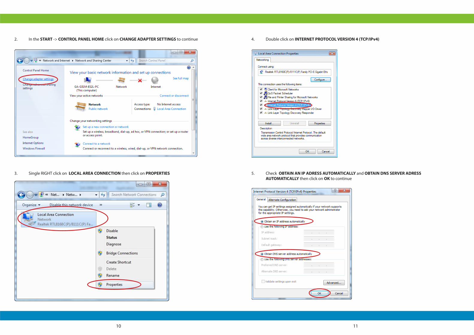
2. In the START -> CONTROL PANEL HOME click on CHANGE ADAPTER SETTINGS to continue
3. Single RIGHT click on LOCAL AREA CONNECTION then click on PROPERTIES
4. Double click on INTERNET PROTOCOL VERSION 4 (TCP/IPv4)
5. Check OBTAIN AN IP ADRESS AUTOMATICALLY and OBTAIN DNS SERVER ADRESS AUTOMATICALLY then click on OK to continue
12 13
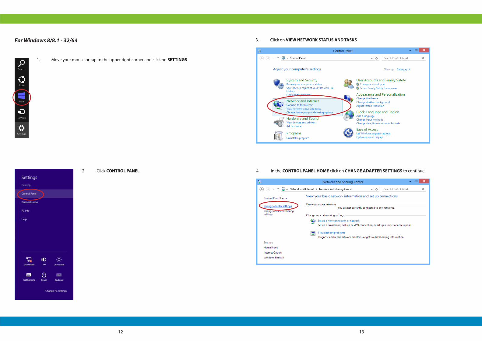
For Windows 8/8.1 - 32/64
1. Move your mouse or tap to the upper right corner and click on SETTINGS
2. Click CONTROL PANEL
3. Click on VIEW NETWORK STATUS AND TASKS
4. In the CONTROL PANEL HOME click on CHANGE ADAPTER SETTINGS to continue
14 15
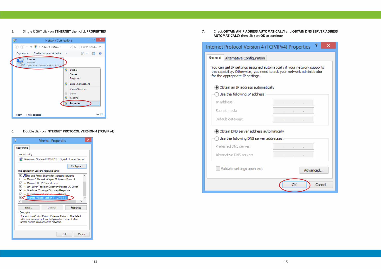
5. Single RIGHT click on ETHERNET then click PROPERTIES
6. Double click on INTERNET PROTOCOL VERSION 4 (TCP/IPv4)
7. Check OBTAIN AN IP ADRESS AUTOMATICALLY and OBTAIN DNS SERVER ADRESS AUTOMATICALLY then click on OK to continue
16 17
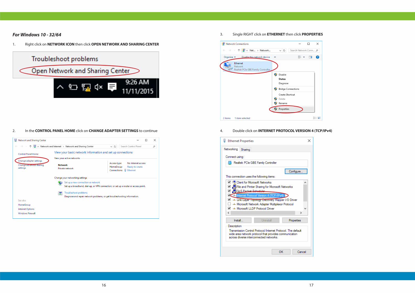
For Windows 10 - 32/64
1. Right click on NETWORK ICON then click OPEN NETWORK AND SHARING CENTER
2. In the CONTROL PANEL HOME click on CHANGE ADAPTER SETTINGS to continue
3. Single RIGHT click on ETHERNET then click PROPERTIES
4. Double click on INTERNET PROTOCOL VERSION 4 (TCP/IPv4)

18 19
5. Check OBTAIN AN IP ADRESS AUTOMATICALLY and OBTAIN DNS SERVER ADRESS AUTOMATICALLY then click on OK to continue
For MAC OS X 10.6
1. From the APPLE MENU select SYSTEM PREFERENCES
2. Click on the NETWORK ICON in the INTERNET & NETWORK AREA
3. From the SHOW pull-down select BUILT-IN ETHERNET. On the TCP/IP TAB, select USING DHCP from the CONFIGURE pull-down menu
20 21
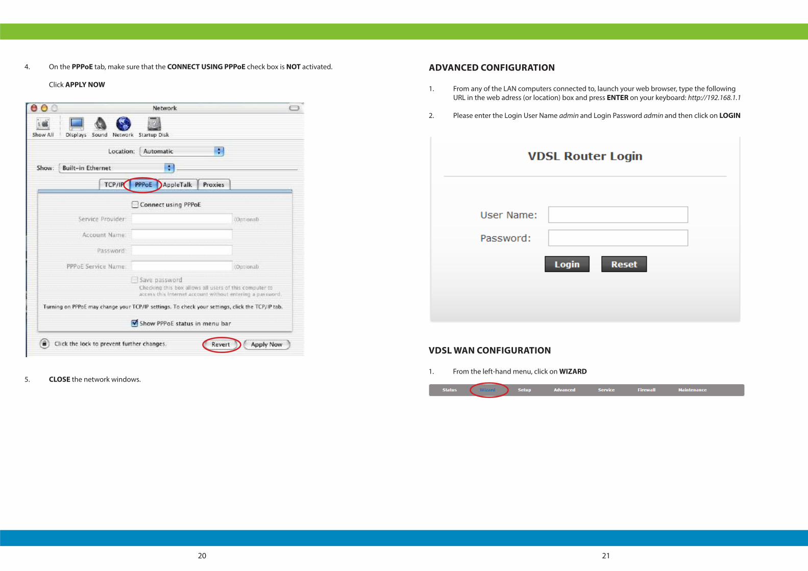
4. On the PPPoE tab, make sure that the CONNECT USING PPPoE check box is NOT activated.
Click APPLY NOW
5. CLOSE the network windows.
ADVANCED CONFIGURATION
1. From any of the LAN computers connected to, launch your web browser, type the following URL in the web adress (or location) box and press ENTER on your keyboard: http://192.168.1.1
2. Please enter the Login User Name admin and Login Password admin and then click on LOGIN
VDSL WAN CONFIGURATION
1. From the left-hand menu, click on WIZARD
22 23
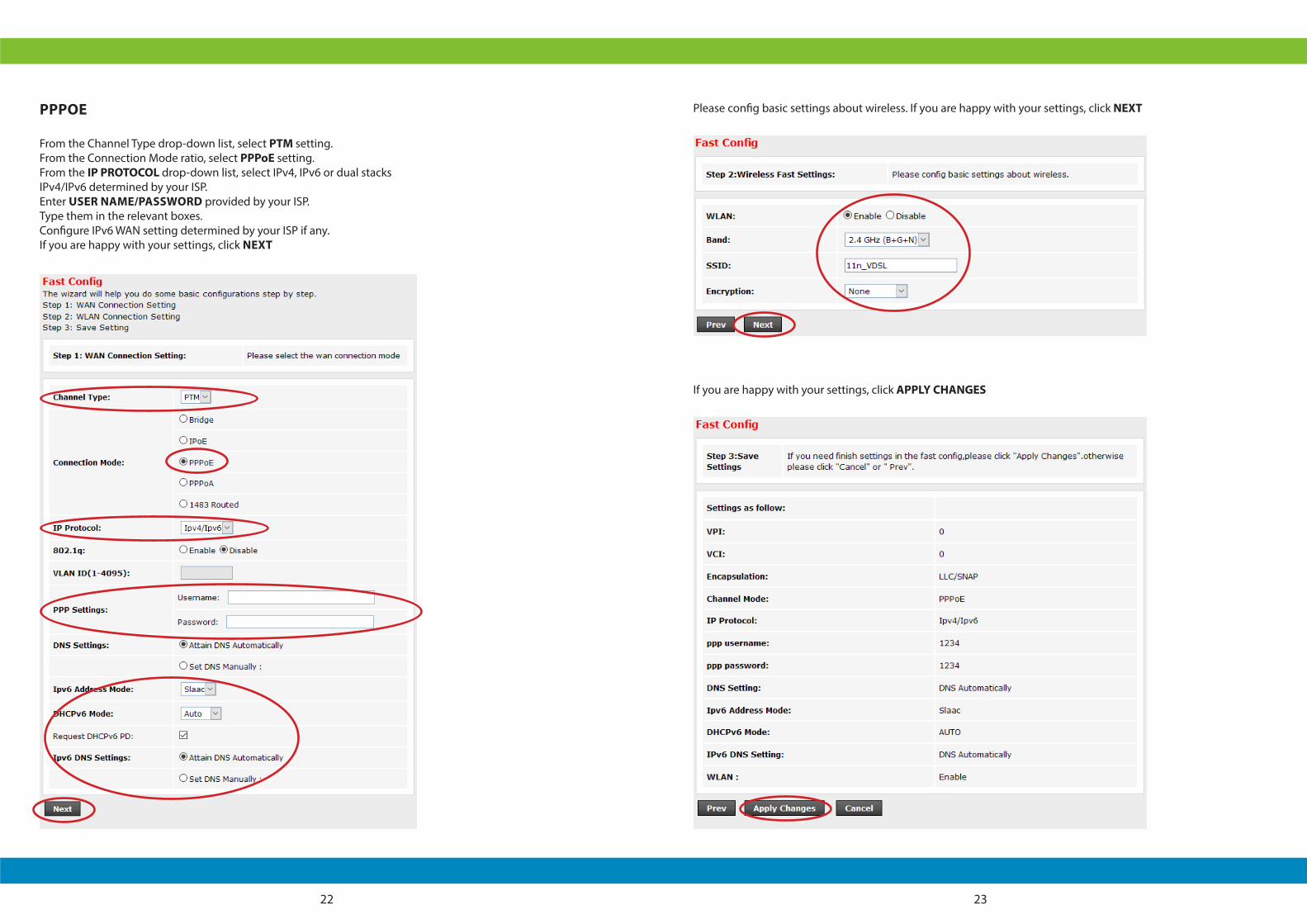
PPPOE
From the Channel Type drop-down list, select PTM setting.From the Connection Mode ratio, select PPPoE setting.From the IP PROTOCOL drop-down list, select IPv4, IPv6 or dual stacks IPv4/IPv6 determined by your ISP.Enter USER NAME/PASSWORD provided by your ISP. Type them in the relevant boxes.Configure IPv6 WAN setting determined by your ISP if any.If you are happy with your settings, click NEXT
Please config basic settings about wireless. If you are happy with your settings, click NEXT
If you are happy with your settings, click APPLY CHANGES
24 25
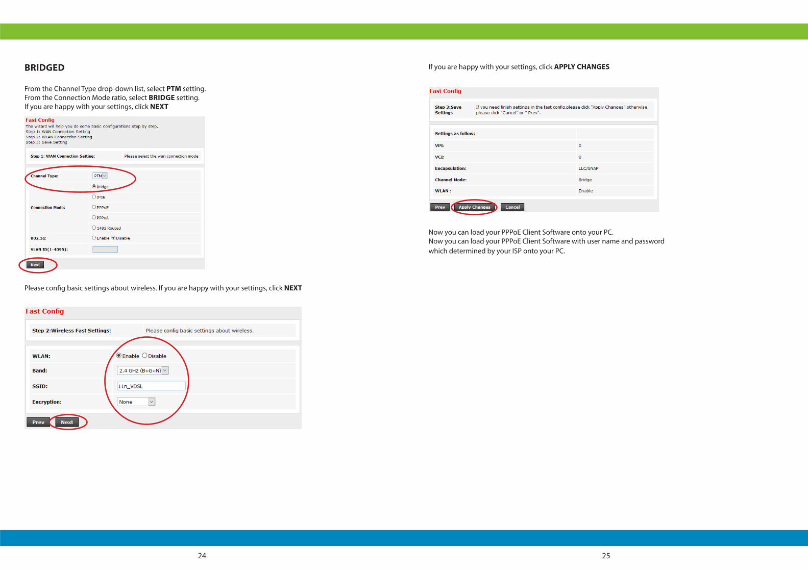
BRIDGED
From the Channel Type drop-down list, select PTM setting.From the Connection Mode ratio, select BRIDGE setting.If you are happy with your settings, click NEXT
Please config basic settings about wireless. If you are happy with your settings, click NEXT
If you are happy with your settings, click APPLY CHANGES
Now you can load your PPPoE Client Software onto your PC.Now you can load your PPPoE Client Software with user name and password which determined by your ISP onto your PC.

26 27
IPOE BY DHCP
From the Channel Type drop-down list, select PTM setting.From the Connection Mode ratio, select IPoE setting.From the IP PROTOCOL drop-down list, select IPv4, IPv6 or dual stacks IPv4/IPv6 determined by your ISP.Configure IPv6 WAN setting determined by your ISP if any.If you are happy with your settings, click NEXT
Please config basic settings about wireless. If you are happy with your settings, click NEXT
If you are happy with your settings, click APPLY CHANGES
28 29
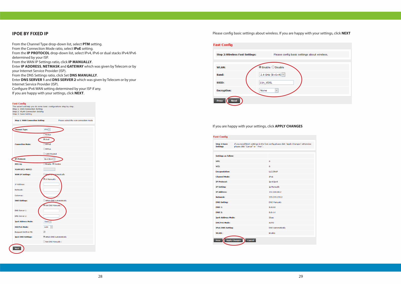
IPOE BY FIXED IP
From the Channel Type drop-down list, select PTM setting.From the Connection Mode ratio, select IPoE setting.From the IP PROTOCOL drop-down list, select IPv4, IPv6 or dual stacks IPv4/IPv6 determined by your ISP.From the WAN IP Settings ratio, click IP MANUALLY.Enter IP ADDRESS, NETMASK and GATEWAY which was given by Telecom or by your Internet Service Provider (ISP).From the DNS Settings ratio, click Set DNS MANUALLY.Enter DNS SERVER 1 and DNS SERVER 2 which was given by Telecom or by your Internet Service Provider (ISP).Configure IPv6 WAN setting determined by your ISP if any.If you are happy with your settings, click NEXT.
Please config basic settings about wireless. If you are happy with your settings, click NEXT
If you are happy with your settings, click APPLY CHANGES
30 31
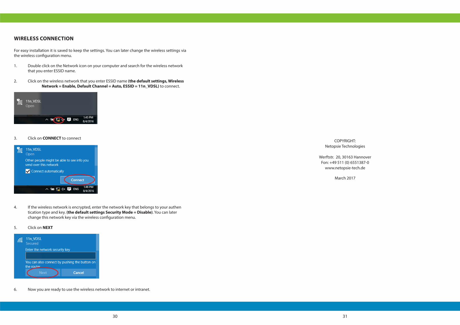
WIRELESS CONNECTION
For easy installation it is saved to keep the settings. You can later change the wireless settings via the wireless configuration menu.
1. Double click on the Network icon on your computer and search for the wireless network that you enter ESSID name.
2. Click on the wireless network that you enter ESSID name (the default settings, Wireless Network = Enable, Default Channel = Auto, ESSID = 11n_VDSL) to connect.
3. Click on CONNECT to connect
4. If the wireless network is encrypted, enter the network key that belongs to your authen tication type and key. (the default settings Security Mode = Disable). You can later change this network key via the wireless configuration menu.
5. Click on NEXT
6. Now you are ready to use the wireless network to internet or intranet.
COPYRIGHT:
Netopsie Technologies
Werftstr. 20, 30163 Hannover Fon: +49 511 (0) 6551387-0
www.netopsie-tech.de
March 2017