808 d op_milling_0113_en
TRANSCRIPT

Sinumerik 808D Programming and Operating Procedures for Milling Version 2013-01
s
Training manual

Operating and Programming — Milling Page 2 808D
Notes
s

808D Page 3 Operating and Programming — Milling
s
Create Part Program
Part 2
Pages 39~51
ISO Mode
Pages 97~106
Contents
End
Switch On and Referencing
Pages 9~10
Test Program
Pages 57~58
Additional Information
Part 1
Pages 69~75
Tool Setup
Pages 13~20
Additional Information
Part 2
Pages 77~85
Machine Pieces
Pages 61~63
Appendix
Pages 109~112
Program Restart
Pages 65~66
Simulate Program
Pages 53~54
Workpiece Setup
Pages 23~27
Preparation
Pages 5~7
Sample Program
Pages 87~94
Create Part Program
Part 1
Pages 29~36
Basic knowledge of programming for milling is required, before operating of a machine !
Operating and Programming — Milling Page 4 808D
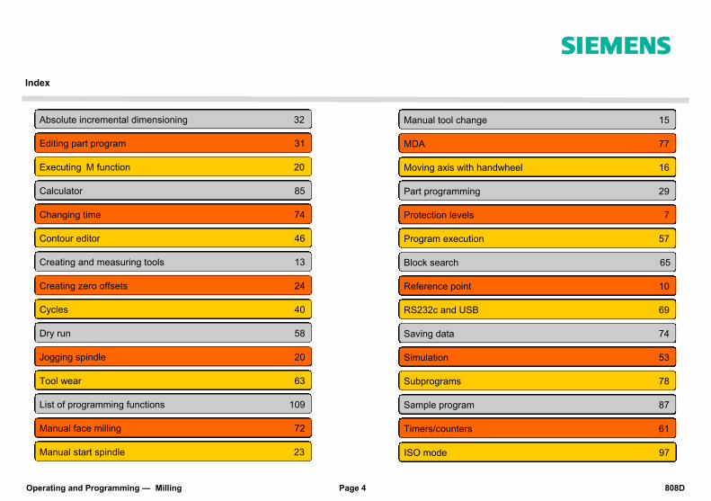
Index
s
Absolute incremental dimensioning 32
Editing part program 31
Executing M function 20
Calculator 85
Changing time 74
Contour editor 46
Creating and measuring tools 13
Creating zero offsets 24
Cycles 40
Dry run 58
Jogging spindle 20
Manual start spindle 23
Manual face milling 72
List of programming functions 109
Tool wear 63
Manual tool change 15
MDA 77
Moving axis with handwheel 16
Part programming 29
Protection levels 7
Program execution 57
Block search 65
Reference point 10
RS232c and USB 69
Saving data 74
Simulation 53
Timers/counters 61
Sample program 87
Subprograms 78
ISO mode 97

808D Page 5 Operating and Programming — Milling
Preparation s Content
Unit Description This unit describes the 808D PPU and MCP functionality, the coordinate system of a milling machine and how to enter passwords to access the system.
Unit Content
PPU Function of keyboard
MCP mode Changing
MCP Moving axis
MCP OEM keys
Machine coordinate
system
User interface
Passwords
PPU Function of keyboard
The 808D panel pro-cessing unit (PPU) is used to input data to the CNC and to navi-gate to operating areas of the system.
Menu navigation Operating area navigation
MCP mode Changing
Mode Navigation The 808D machine control panel (MCP) is used to select the machine operating mode : JOG - MDA - AUTO
Basic Theory
End

Operating and Programming — Milling Page 6 808D
Preparation s
MCP Moving axis
Axis remove
The 808D machine control panel (MCP) is used to con-trol manual operation of the axis. The machine can be moved with the appropriate keys.
MCP OEM keys
OEM keys
The 808D machine control panel (MCP) is used to con-trol OEM machine functions. The machine functions can be activated with the appro-priate keys.
User interface
808D (PPU) has eight vertical softkeys (abbr. SKs) on the right of the screen. These SKs can be activated with the corresponding button (located on the right).
808D (PPU) has eight horizontal SKs on the bottom of the screen. These SKs can be activated with the corresponding button (located below).

808D Page 7 Operating and Programming — Milling
Preparation s
Machine coordinate system
The Sinumerik 808D uses a coordinate system which is derived from the DIN 66217 standard. The system is an international standard and ensures com-patibility between machines and coordinate programming. The primary function of the coordinate system is to en-sure that the tool length and tool radius are calculated correctly in the respective axis.
Passwords
Passwords at the control are used to set the user’s right to access the system. Tasks such as ”Basic Op-erating”, “Advanced Operating” and commissioning functions all depend on the passwords. No password Customer’s password Manufacturer’s password Customer’s password = CUSTOMER Manufacturer’s password = SUNRISE Changing
password
Step 1
The service mode is opened with the appropriate key combination. In the service mode, the password can be activated and deactivated.
Step 2
Enter customer’s or manufacturer’s password
Change customer’s or manufacturer’s password
Delete customer’s or manufacturer’s password
End
Usually the machine operator does not need to change the password.
+
Machine operator Advanced operator OEM engineer
SEQUENCE
Operating and Programming — Milling Page 8 808D
Notes
s
808D Page 9 Operating and Programming — Milling
Switch On and
Referencing s
Content
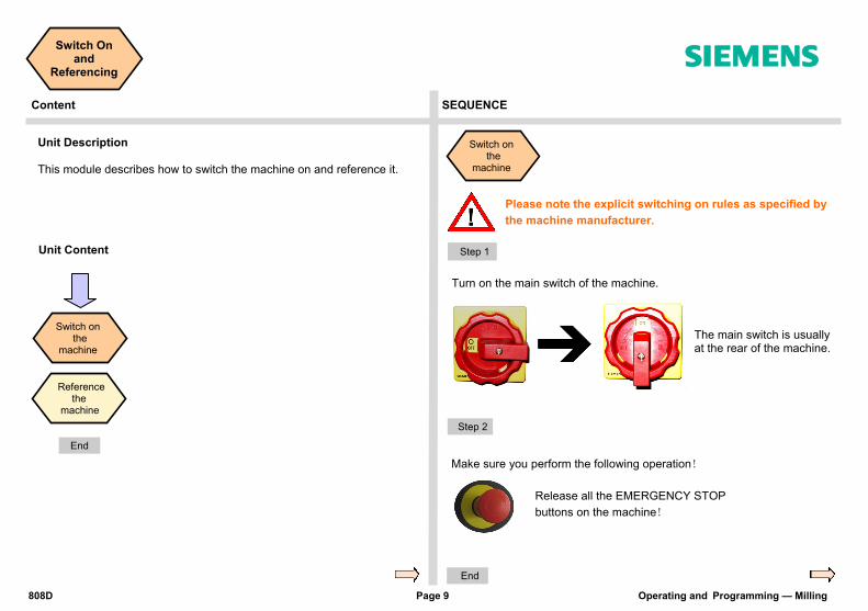
Unit Description This module describes how to switch the machine on and reference it.
Unit Content
Switch on the machine
Reference the machine
Please note the explicit switching on rules as specified by
the machine manufacturer.
Turn on the main switch of the machine.
The main switch is usually at the rear of the machine.
Release all the EMERGENCY STOP
buttons on the machine!
Make sure you perform the following operation!
Step 1
Step 2
End
Switch on the machine
End
SEQUENCE

Operating and Programming — Milling Page 10 808D
Switch On and
Referencing s
Step 3
After completing the referencing procedure for all axes, the refer-enced symbol is displayed next to the axis identifier.
End
After returning to JOG mode, use the axis traversing keys to move the machine manually.
The machine can now be operated in JOG mode.
During normal operation (JOG),the
referenced symbol is not shown on the screen.
After power on, the machine must first
be referenced!
Step 1
After power on, the machine will be in the reference point approach mode (default).
If the axis is not referenced, the non-referenced symbol (circle) is dis-played between the axis identifier and the value.
Step 2
The axes are referenced with the corresponding axis traversing keys.
The traversing direction and keys are specified by the machine manu-facturer.
Reference the
machine
SEQUENCE
808D Page 11 Operating and Programming — Milling
Notes
s
Operating and Programming — Milling Page 12 808D
Notes
s
808D Page 13 Operating and Programming — Milling
Tool Setup s Content SEQUENCE
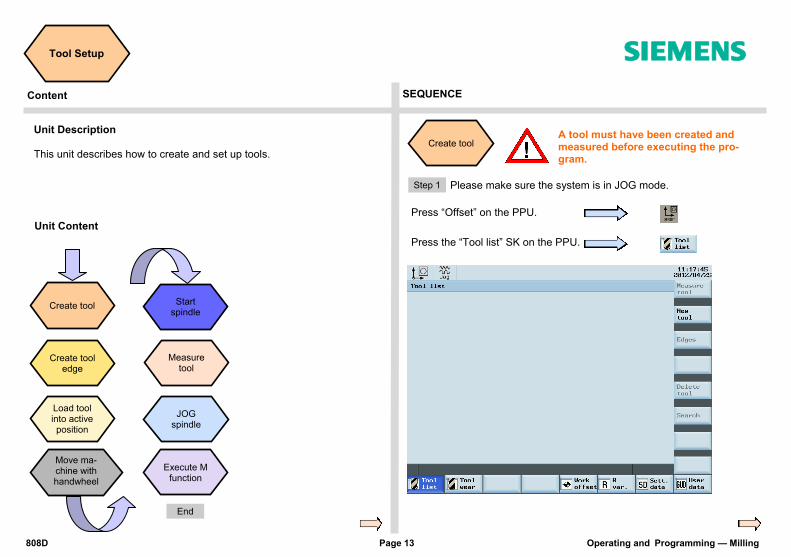
Unit Description This unit describes how to create and set up tools.
Unit Content
Create tool
Load tool into active position
Measure tool
Move ma-chine with handwheel
JOG spindle
Execute M function
Start spindle
Create tool A tool must have been created and measured before executing the pro-gram.
Step 1
Press “Offset” on the PPU.
Please make sure the system is in JOG mode.
Create tool edge
Press the “Tool list” SK on the PPU.
End

Operating and Programming — Milling Page 14 808D
Tool Setup s
Step 2
Press the “New tool” SK on the PPU.
Enter “1” at “Tool No.”
Press the “OK” SK on the PPU.
Enter the ”Radius” of the milling tool.
Select the type of tool required.
Press the “Input” button on the PPU.
Create tool edge
Step 1
Press the “Offset” key on the PPU.
A tool must have been created and
selected before creating a tool edge!
Press the “Edges” SK on the PPU.
Use “D” code to specify the tool edge. The system activates tool edge no. 1 per default at the start.
Use direction keys to select the tool
which needs to add a tool edge. Or
Press the “New edge” SK on the PPU.
Press the “Tool list” SK on the PPU.
The range of tool numbers which can be created by this system is 1 ~32000. The machine can be loaded with a maximum of 64 tools / 128 tool edges.
SEQUENCE

808D Page 15 Operating and Programming — Milling
Tool Setup s
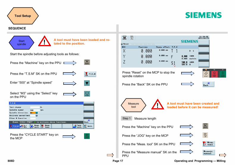
Press the “Machine” key on the PPU
Press the “T.S.M” SK on the PPU
Enter tool number “1” in “T”
Press “CYCLE START” on the MCP
Load tool into Spindle
Press the “Back” SK on the PPU
A tool must have been created in the system before it can be loaded into the active position.
Press the “JOG” key on the MCP
Step 2
The red circle shows the actual active tool and tool edge,the purple circle
shows how many tool edges have been created and the related data for each tool edge.
A new tool edge can be added in this way and different lengths and radii can be entered as required.
A maximum of nine tool edges can be created for each tool! Different tool lengths and radii can be saved in different tool edges as required. Please select the right tool edge for machining according to requirement!
SEQUENCE

Operating and Programming — Milling Page 16 808D
Tool Setup s
The tool are usually loaded manually into the spindle.
The tool will be automatically loaded into the spindle with an automatic tool changer.
Move ma-chine with handwheel
A handwheel can control the axis motion instead of the “JOG” button.
Press the “Machine” key on the PPU
Make sure there is no obstruction when moving the tool to avoid a crash.
Press the “Handwheel” key on the MCP
Select the required override increment according to the buttons on the right
(this selection fits all axes)
The selected axis can now be moved with the handwheel.
Press “JOG” on MCP to end the function of “Handwheel”.
The override increment is “0.001 mm”
The override increment is “0.010 mm”
The override increment is “0.100 mm”
Select the required axis on the right of the PPU; the se-lected axis is
shown with a √
Notes:If set the MD14512[16]=80, the system will deactivate the
function of MCP for selecting the axis of handwheel, the user will have to activate “Handwheel” function with PPU softkey. Select the axis you want to move with
the appropriate keys. on the MCP
Under “WCS” or “MCS” state, a handwheel will be shown beside the axis symbols, showing the axis is chosen, and can be controlled with a handwheel.
SEQUENCE
808D Page 17 Operating and Programming — Milling
Tool Setup s
Press the “CYCLE START” key on the MCP
Press the “Back” SK on the PPU
Press “Reset” on the MCP to stop the spindle rotation
A tool must have been created and loaded before it can be measured!
Measure tool
Step 1
Press the “Meas. tool” SK on the PPU
Press the “Measure manual” SK on the PPU
Press the “Machine” key on the PPU
Press the “JOG” key on the MCP
Measure length
Press the “Machine” key on the PPU
Press the “T.S.M” SK on the PPU
Enter “500” at “Spindle speed”
Select “M3” using the “Select” key on the PPU
Start the spindle before adjusting tools as follows:
A tool must have been loaded and ro-tated to the position.
Start spindle
SEQUENCE
Operating and Programming — Milling Page 18 808D
Tool Setup s
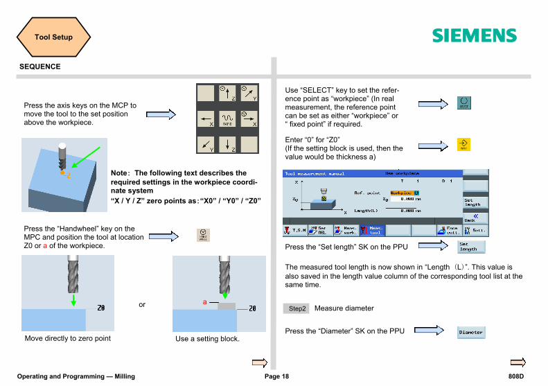
Press the “Set length” SK on the PPU
Enter “0” for “Z0” (If the setting block is used, then the value would be thickness a)
Press the “Handwheel” key on the MPC and position the tool at location Z0 or a of the workpiece.
or
Move directly to zero point Use a setting block.
a
Press the “Diameter” SK on the PPU
Step2 Measure diameter
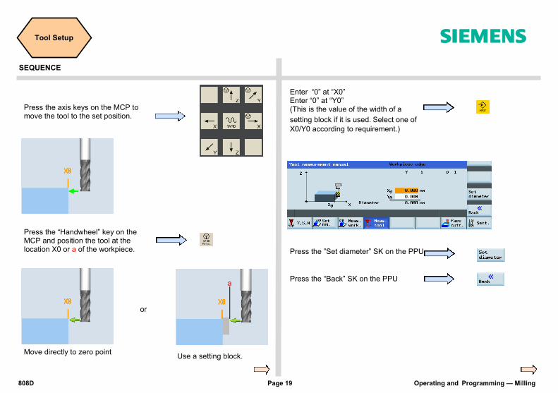
Press the axis keys on the MCP to move the tool to the set position above the workpiece.
The measured tool length is now shown in “Length (L)”. This value is
also saved in the length value column of the corresponding tool list at the same time.
Note: The following text describes the
required settings in the workpiece coordi-nate system
“X / Y / Z” zero points as:“X0” / “Y0” / “Z0”
Use “SELECT” key to set the refer-ence point as “workpiece” (In real measurement, the reference point can be set as either “workpiece” or “ fixed point” if required.
SEQUENCE
808D Page 19 Operating and Programming — Milling
Tool Setup s
Press the ”Set diameter” SK on the PPU
Press the “Back” SK on the PPU
Enter “0” at “X0” Enter “0” at “Y0” (This is the value of the width of a
setting block if it is used.Select one of
X0/Y0 according to requirement.)
Press the “Handwheel” key on the MCP and position the tool at the location X0 or a of the workpiece.
or
Move directly to zero point Use a setting block.
a
Press the axis keys on the MCP to move the tool to the set position.
SEQUENCE

Operating and Programming — Milling Page 20 808D
Tool Setup s
Press “Spindle stop” on the MCP to stop the spindle.
Press “Spindle left” on the MCP to start the spindle in the counter-clockwise direction.
Press “Spindle right” on the MCP to start the spindle in the clockwise direction.
Press the “Machine” key on the PPU.
Press the “T.S.M” SK on the PPU.
Use the direction key to move the highlighted cursor to “Other M func-tion” and enter “8”. This will start the coolant.
Press “CYCLE START” on the MCP.
Press the “Back” SK on the PPU.
Please make sure all the machine axes are in safe positions before executing the M function!
Execute M function
Press the “Reset” key on the MCP to stop the coolant function.
The coolant function button on MCP is active.
Jog spindle
Press the “Machine” key on the PPU.
A tool must be loaded to the spindle.
Press the “JOG” key on the MCP.
Press the spindle direction key on the MCP to start/stop the spindle.
SEQUENCE

808D Page 21 Operating and Programming — Milling
Notes
s
Operating and Programming — Milling Page 22 808D
Notes
s

808D Page 23 Operating and Programming — Milling
Workpiece Setup s
Content SEQUENCE
Unit Description This unit describes how to set the workpiece offset and test the tool re-sults.
Unit Content
Create workpiece
offset
Manual start
spindle
Manual start
spindle
A tool must have been loaded into the spindle.
Press the “Machine” key on the PPU.
Press the “T.S.M” SK on the PPU.
Enter “500” in “Spindle speed” on the PPU.
Press “CYCLE START” on the MCP.
Select “M3” as the “Spindle direc-tion” using the “Select” key on the PPU.
Press the “JOG” key on the MCP.
Before measuring, the spindle can be started as follows:
Test tool offset results
End
Operating and Programming — Milling Page 24 808D
Workpiece Setup s
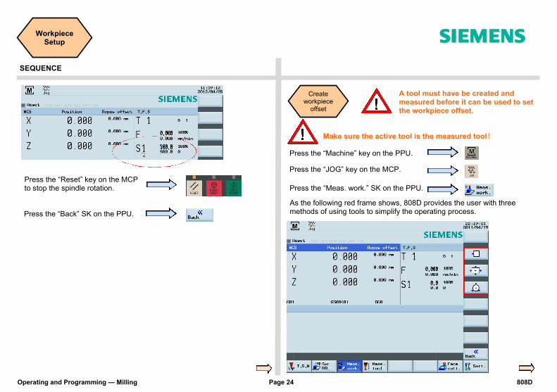
Press the “Back” SK on the PPU.
Press the “Reset” key on the MCP to stop the spindle rotation.
Create workpiece
offset
A tool must have be created and measured before it can be used to set the workpiece offset.
Press the “Machine” key on the PPU.
Press the “JOG” key on the MCP.
Press the “Meas. work.” SK on the PPU.
Make sure the active tool is the measured tool!
As the following red frame shows, 808D provides the user with three methods of using tools to simplify the operating process.
SEQUENCE

808D Page 25 Operating and Programming — Milling
Workpiece Setup s
This method is normally for setting the zero point of the work-piece at the edge of the workpiece.
Method1
Press the corresponding SK of the first icon on the right-hand side of the PPU.
Using a tool that has a measured “Tool length & radius”, move the tool to a known position on the workpiece. Using either JOG or Handwheel, scratch an edge and then calculate the zero point of the workpiece. The process of setting the “X” zero point (“X0”) is described below.
Press the appropriate SK to select the feed axis which needs to be set up.
Press the axis traverse keys to move the tool to the required set-ting position in the X axis.
Press the “Handwheel” key on the MCP to position the tool at the X0 edge of the work-piece.
Set “Distance” as “0”.
Select “Save in” Offset “G54” (or other offset).
Select “Measuring direction” as “-”. (This value should be chosen according to realities)
Press the “Set WO” SK on the PPU.
“Step 2” must be repeated for the setting of Y and Z zero points. If you change the tool because of wear/damage during the machining process, you must remeasure the length of the tool.
SEQUENCE

Operating and Programming — Milling Page 26 808D
Workpiece Setup s
SEQUENCE
This method is normally used for setting the workpiece zero point at the center point of a rectangular workpiece.
Method 2
Press the corresponding SK of the second icon on the right-hand side of the PPU.
Using tools with a measured “length and radius”, move them to the four
edges of the rectangular workpiece. Using either JOG or Handwheel,
scratch an edge and then calculate the zero point of the workpiece.
Observing the figure on the PPU, move the coordinate axis following the orange arrow to move the tool to the specified position and scratch the edge of the workpiece.
Press the ”Save P1” SK on the PPU to save the coor-dinate axis of the 1st position in the system.
Press the “Set WO” SK on the PPU.
You have then finished setting the zero point of the workpiece as the center point of the
rectangular workpiece.
Repeat the process for positions 2, 3 and 4. (When the setting is complete, the buttons will be shown in blue.)
This method is normally used for setting the zero points at the center point of a circular workpiece.
Method 3
Press the corresponding SK of the third icon on the right-hand side of the PPU.
Using tools with a measured “length and radius”, move them to the three
edges of the circular workpiece. Using either JOG or Handwheel, scratch
an edge and then calculate the zero point of the workpiece.
Observing the figure on the PPU, move the coordinate axis following the orange arrow to move the tool to the specified position and scratch the edge of the workpiece.
Press the ”Save P1” SK on the PPU to save the coordinate axis of the 1st position in the system.
Press the “Set WO” SK on the PPU.
You have then finished setting the zero point of the workpiece as the center point of the circular
workpiece.
Repeat the process for positions 2 and 3.
(When the setting is complete, the buttons will be
shown in blue.)

808D Page 27 Operating and Programming — Milling
Workpiece Setup s
SEQUENCE
The tool setup and workpiece setup must have been performed correctly so
that it can be tested as follows!
Press the “MDA” key on the MCP.
Press the “Delete file” SK on the PPU.
Press “CYCLE START” on the MCP.
Enter the test program recommend-ed on the right. (can also be cus-tomized)
G54 (select offset panel as required) T1 D1 G00 X0 Y0 Z5
Test tool offset results
Press the “ROV” key to ensure that the “ROV” function is activated (the function is activated when the light on the key is on ).
Make sure the feedrate override on the MCP is at 0%!
Increase the feedrate override gradually to avoid accidents caused by an axis moving too fast. Observe whether the axis moves to the set position.
Note: The ROV function activates the feedrate override switch under
the G00 function.
Press the “Machine” key on the PPU.
In order to ensure the machine safety and correctness, the results of the tool offset should be tested appropriately.

Operating and Programming — Milling Page 28 808D
Notes
s
808D Page 29 Operating and Programming — Milling
Create Part Program
Part 1 s
Basic Theory Content
Unit Description This unit describes how to create a part program, edit the part program and get to know the most important CNC commands required to produce a workpiece.
Unit Content
Program structure
Create program
Edit program
Imperial and Metric
system
Definition of target position
Rapid motion
Tools and motion
Behaviors at corners
Milling circles and
arcs
Moving to a fixed
position
Controlling the spindle
Setting a delay in the
program
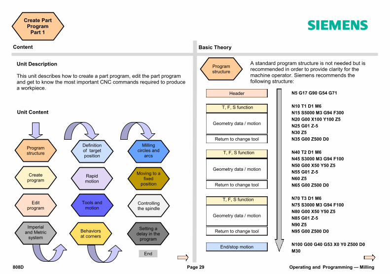
Program structure
A standard program structure is not needed but is recommended in order to provide clarity for the machine operator. Siemens recommends the following structure:
Header
T, F, S function
Geometry data / motion
Return to change tool
T, F, S function
Geometry data / motion
Return to change tool
T, F, S function
Geometry data / motion
Return to change tool
End/stop motion
N5 G17 G90 G54 G71
N10 T1 D1 M6
N15 S5000 M3 G94 F300
N20 G00 X100 Y100 Z5
N25 G01 Z-5
N30 Z5
N35 G00 Z500 D0
N40 T2 D1 M6
N45 S3000 M3 G94 F100
N50 G00 X50 Y50 Z5
N55 G01 Z-5
N60 Z5
N65 G00 Z500 D0
N70 T3 D1 M6
N75 S3000 M3 G94 F100
N80 G00 X50 Y50 Z5
N85 G01 Z-5
N90 Z5
N95 G00 Z500 D0
N100 G00 G40 G53 X0 Y0 Z500 D0
M30 End

Operating and Programming — Milling Page 30 808D
Create Part Program
Part 1 s
Create program
The following sequence should be followed to create a part program:
Step 1
Programs can be created with the “program manager”. You can select the “program manager” using the key located on the PPU.
Step 2
Select NC as the storage location for the program. Programs can only be created in the NC.
Step 3
Create a new pro-gram with the “New” SK on the right of the PPU.
Step 4
You can choose “New” or “New direc-tory”. Choose “New” to create a program.
Choose “New direc-tory” to cre-ate a file.
Step 5
End
Now the program is opened and can be edit-ed.
The system will save it automatically after editing.
1
2
SEQUENCE

808D Page 31 Operating and Programming — Milling
Create Part Program
Part 1 s
Basic Theory
Edit program
The program shown in the editor can be created and edited with the appropriate keys.
Inches and mm
Header
T,F,S function
Geometry data / motion
Return to change tool
N5 G17 G90 G54 G71
N10 T1 D1 M6
N15 S5000 M3 G94 F300
N20 G00 X100 Y100 Z5
N25 G01 Z-5
N30 Z5
N35 G00 Z500 D0
G71 With G71 at the header, the ge-ometry data will be in the metric unit system, the feedrate in the default metric system.
Header
T,F,S function
Geometry data / motion
Return to change tool
N5 G17 G90 G54 G70
N10 T1 D1 M6
N15 S5000 M3 G94 F300
N20 G00 X3.93 Y3.93 Z5
N25 G01 Z-0.787
N30 Z0.196
N35 G00 Z19.68 D0
G70 With G70 at the header, the ge-ometry data will be in the imperial (inches) unit system, the feedrate in the default metric system.

Operating and Programming — Milling Page 32 808D
Create Part Program
Part 1 s
Basic Theory
Definition of target position
N5 G17 G90 G54 G71
N10 T1 D1 M6
N15 S5000 M3 G94 F300
N20 G00 X100 Y100 Z5
N25 G01 Z-20
N30 Z5
N35 G00 Z500 D0
G90 Absolute positioning; with G90 at the header, the geometry data which follows will be interpret-ed relative to the active zero point in the pro-gram, usually with G54 or G500 or G500 + G54.
N5 G17 G90 G54 G70
N10 T1 D1 M6
N15 S5000 M3 G94 F300
N20 G00 X3.93 Y3.93 Z0.196
N25 G01 G91 Z-0.787
N30 Z0.196
N35 G00 G90 Z19.68 D0
G91
Relative positioning; with G91 you can add an incremental value
(G91-defined data is the
relative positioning using the present posi-
tion as the start point). Finally you should change the program to absolute positioning with G90.
G54 G55 G56 G57 G58 G59 With G500 = 0, the offset for the work-piece can be stored in the G54 workpiece offset.
G500 All absolute path data will be relative to this position. The position is written in the G500 (basic) zero offset.
G500 + G54 With G500 unequal to 0 and be activat-ed, the value in G500 will be added to the value in G54.
N5 G17 G90 G500 G71 N10 T1 D1 M6 N15 S5000 M3 G94 F300 N20 G00 X50 Y50 Z5 N25 G01 Z-20 N30 Z5 N35 G00 Z500 D0
G500 Y
G500 X
X50 Y50
N5 G17 G90 G54 G71 N10 T1 D1 M6 N15 S5000 M3 G94 F300 N20 G00 X0 Y0 Z5 N25 G01 Z-20 N30 Z5 N35 G00 Z500 D0
G500 Y
G500 X
G54 X0 G54 Y0
N5 G17 G90 G500 G71 N10 T1 D1 M6 N15 S5000 M3 G94 F300 N20 G00 G54 X20 Y20 Z5 N25 G01 Z-20 N30 Z5 N35 G00 G53 Z500 D0
Or
Or
G54 Y
G54 X
X50 Y50

808D Page 33 Operating and Programming — Milling
Create Part Program
Part 1 s
Basic Theory
Rapid motion
G00 When G00 is activated in the program, the axis will traverse at the maximum axis speed in a straight line.
N5 G17 G90 G54 G71 N10 T1 D1 M6 N15 S5000 M3 G94 F300 N20 G00 X50 Y50 Z5 N25 G01 Z-5 N30 Z5 N35 G00 Z500 D0
Tools and motion
T1 D1 M06 Using the “T” com-mand, the new tool can be selected. The ”D” command is used to activates the tool length off-set. M06 can be also used for machines with automatic tool changer.
N5 G17 G90 G54 G71 N10 T1 D1 M6 N15 S5000 M3 G94 F300 N20 G00 X50 Y50 Z5 N25 G01 Z-20 N30 Z5 N35 G00 Z500 D0
Feedrate
Spindle speed
Feed type
Spindle direction
In the program, the feed rate is defined with “F”. Two types of feed rate are available:
1. Feed per minute →G94
2. Feed per revolution of the spin-
dle →G95 G94 Defines the feed rate in terms of time (unit: mm/min). G95 Defines the feed rate in terms of spindle revolutions (unit: mm/rev). S The spindle speed is defined with ”S” S5000 M3/M4 The spindle direction is defined with M3 and M4, clockwise and counter-clockwise respectively. G01 When G01 is activated in the pro-gram, the axis will traverse at the programmed feed rate in a straight line, according to the feed rate type defined by G94 or G95.
N5 G17 G90 G54 G71 N10 T1 D1 M6 N15 S5000 M3 G94 F300 N20 G00 X50 Y50 Z5 N25 G01 Z-5 N30 Z5 N35 G00 Z500 D0
N5 G17 G90 G54 G71 N10 T1 D1 M6 N15 S5000 M3 G95 F0.3 N20 G00 X50 Y50 Z5 N25 G01 Z-5 N30 Z5 N35 G00 Z500 D0
Straight line (parallel/unparallel to axis)
Straight line (parallel/unparallel to axis)
Operating and Programming — Milling Page 34 808D
Create Part Program
Part 1 s
Basic Theory
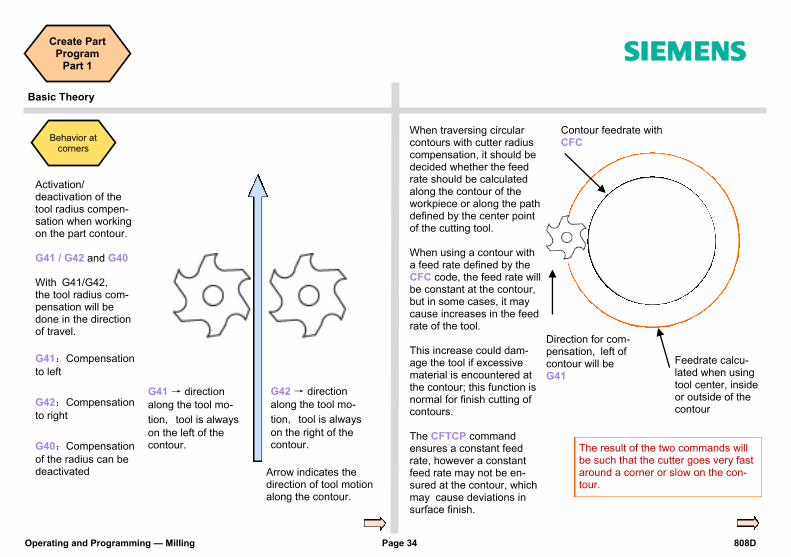
Behavior at corners
Activation/deactivation of the tool radius compen-sation when working on the part contour. G41 / G42 and G40 With G41/G42, the tool radius com-pensation will be done in the direction of travel.
G41:Compensation
to left
G42:Compensation
to right
G40:Compensation
of the radius can be deactivated Arrow indicates the
direction of tool motion along the contour.
G41 → direction
along the tool mo-
tion, tool is always
on the left of the contour.
G42 → direction
along the tool mo-
tion, tool is always
on the right of the contour.
Contour feedrate with CFC
Direction for com-pensation, left of contour will be G41
Feedrate calcu-lated when using tool center, inside or outside of the contour
The result of the two commands will be such that the cutter goes very fast around a corner or slow on the con-tour.
When traversing circular contours with cutter radius compensation, it should be decided whether the feed rate should be calculated along the contour of the workpiece or along the path defined by the center point of the cutting tool. When using a contour with a feed rate defined by the CFC code, the feed rate will be constant at the contour, but in some cases, it may cause increases in the feed rate of the tool. This increase could dam-age the tool if excessive material is encountered at the contour; this function is normal for finish cutting of contours. The CFTCP command ensures a constant feed rate, however a constant feed rate may not be en-sured at the contour, which may cause deviations in surface finish.
808D Page 35 Operating and Programming — Milling
Create Part Program
Part 1 s
Basic Theory
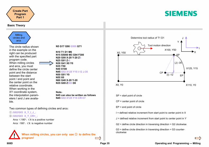
Milling circles and arcs
SP = start point of circle
CP = center point of circle
EP = end point of circle
I = defined relative increment from start point to center point in X
J = defined relative increment from start point to center point in Y
X0, Y0
X0, Y50 X100, Y50
X125, Y15
X110, Y0
X
Y
CP
SP
EP
I
J
(I) -12
G2 = define circle direction in traversing direction = G2 clockwise
G3 = define circle direction in traversing direction = G3 counter-clockwise
The circle radius shown in the example on the right can be produced with the specified part program code. When milling circles and arcs, you must define the circle center point and the distance between the start point / end point and the center point on the relative coordinate. When working in the XY coordinate system, the interpolation param-eters I and J are availa-ble.
N5 G17 G90 G500 G71 N10 T1 D1 M6 N15 S5000 M3 G94 F300 N20 G00 X-20 Y-20 Z5 N25 G01 Z-5 N30 G41 X0 Y0 N35 Y50 N40 X100 N45 G02 X125 Y15 I-12 J-35 N50 G01 Y0 N55 X0 N60 G40 X-20 Y-20 N35 G00 Z500 D0
Note: N45 can also be written as follows N45 G02 X125 Y15 CR=37
Determine tool radius of T1 D1
Two common types of defining circles and arcs:
①:G02/G03 X_Y_I_J_;
②:G02/G03 X_Y_CR=_;
Arcs ≤180º,CR is a positive number
Arcs >180º,CR is negative number
Tool motion direction
(J) -35
When milling circles, you can only use ① to define the
program!
Operating and Programming — Milling Page 36 808D
Create Part Program
Part 1 s
Basic Theory
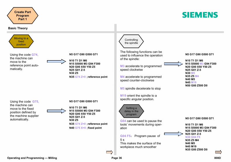
Moving to a fixed
position
Using the code G74, the machine can move to the reference point auto-matically.
N5 G17 G90 G500 G71 N10 T1 D1 M6 N15 S5000 M3 G94 F300 N20 G00 X50 Y50 Z5 N25 G01 Z-5 N30 Z5
N35 G74 Z=0 ;reference point
Using the code G75, the machine can move to the fixed position defined by the machine supplier automatically.
N5 G17 G90 G500 G71 N10 T1 D1 M6 N15 S5000 M3 G94 F300 N20 G00 X50 Y50 Z5 N25 G01 Z-5 N30 Z5
N35 G74 Z=0 ;reference point
N40 G75 X=0 ;fixed point
Controlling the spindle
N5 G17 G90 G500 G71 N10 T1 D1 M6 N15 S5000 M3 G94 F300 N20 G00 X50 Y50 Z5 N25 G01 Z-5 N30 M5 N35 Z5 M4 N40 M5 N45 M19 N50 G00 Z500 D0
The following functions can be used to influence the operation of the spindle: M3 accelerate to programmed speed clockwise M4 accelerate to programmed speed counter-clockwise
M5 spindle decelerate to stop M19 orient the spindle to a specific angular position.
Setting a delay in the
program
N5 G17 G90 G500 G71 N10 T1 D1 M6 N15 S5000 M3 G94 F300 N20 G00 X50 Y50 Z5 N25 G01 Z-5 N30 G04 F5 N35 Z5 M4 N40 M5 N45 M19 N35 G00 Z500 D0
G04 can be used to pause the tools’ movements during oper-ation
G04 F5: Program pause of
5 s This makes the surface of the workpiece much smoother

808D Page 37 Operating and Programming — Milling
Notes
s

Operating and Programming — Milling Page 38 808D
Notes
s
808D Page 39 Operating and Programming — Milling
Create Part Program
Part 2 s
Content Basic Theory
Unit Description This unit describes how to create a part program, edit the part program and get to know the most important CNC commands required to produce a workpiece. Part 2
Unit Content
Radius and chamfers
Tapping
Hole centering
Drilling holes
Hole positioning
Contour milling with
cycle
Milling slots and spigots
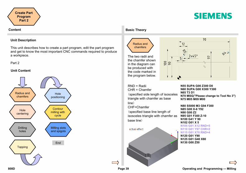
Radius and chamfers
N55 SUPA G00 Z300 D0 N60 SUPA G00 X300 Y300 N65 T3 D1 N70 MSG("Please change to Tool No 3") N75 M05 M09 M00 N80 S5000 M3 G94 F300 N85 G00 X-6 Y92 N90 G00 Z2 N95 G01 F300 Z-10 N100 G41 Y 90 N102 G01 X 5 N105 G01 X12 RND=5 N110 G01 Y97 CHR=2 N115 G01 X70 RND=4 N120 G01 Y90 N125 G01 G40 X80 N130 G00 Z50
The two radii and the chamfer shown in the diagram can be produced with the code marked in the program below.
RND = Radii CHR = Chamfer
(specified side length of isosceles
triangle with chamfer as base
line) CHF=Chamfer
(specified base line length of
isosceles triangle with chamfer as
base line)
End

Operating and Programming — Milling Page 40 808D
Create Part Program
Part 2 s
Basic Theory
→
Hole centering
The easiest way to center drill a hole prior to drilling is to use either CY-CLE81 or CY-CLE82 CYCLE81: With-out delay at cur-rent hole depth CYCLE82: With delay at current hole depth
Select “Deep hole drilling” using the vertical SKs , and then select “Deep hole drilling” ,and parameterize the cycle according to requirements.
N325 MCALL CYCLE82( 50.000, -3.000, 2.000, -5.000, 0.000, 0.200) N330 X20 Y20 ; Hole will be centered N335 X40 Y40 ; Hole will be centered N340 MCALL N345 X60 Y60 ; Hole will not be centered
With the “OK” SK, the values and cycle call will be transferred to the part program as shown be-low. This will drill a hole at the current position. With the Modal call SK, holes will be centered at subsequent programmed positions until cancelled with the MCALL command in the part program. The information is transferred as shown below.
Parameters Meanings
RTP=50 Coordinate value of turning position is 50
(absolute)
RFP=-3 Coordinate value of hole edge starting position under workpiece zero point surface is 3
(absolute)
SDID=2
(frequently
used values
2~5)
Safety distance, feed path changes from quick feed to machine feed 2 mm away from RFP face
DP=-5 Coordinate position of final drilling depth is -5
(absolute)
DTB=0.2 Delay of 0.2 s at final drilling depth
The relevant cycle can now be found using the vertical softkey on the right.
808D Page 41 Operating and Programming — Milling
Create Part Program
Part 2 s
Basic Theory
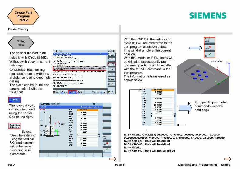
The easiest method to drill
holes is with CYCLE81/82: Without/with delay at current hole depth
CYCLE83:Each drilling
operation needs a withdraw-al distance during deep hole drilling. The cycle can be found and parameterized with the “Drill.” SK.
The relevant cycle can now be found using the vertical SKs on the right.
Select “Deep hole drilling” using the vertical SKs and parame-terize the cycle according to re-quirements.
Drilling holes
With the “OK” SK, the values and cycle call will be transferred to the part program as shown below. This will drill a hole at the current position. With the “Modal call” SK, holes will be drilled at subsequently pro-grammed positions until cancelled with the MCALL command in the part program. The information is transferred as shown below.
For specific parameter commands, see the next page
N325 MCALL CYCLE83( 50.00000, -3.00000, 1.00000, ,9.24000, ,5.00000, 90.00000, 0.70000, 0.50000, 1.00000, 0, 0, 5.00000, 1.40000, 0.60000, 1.60000) N330 X20 Y20 ; Hole will be drilled N335 X40 Y40 ; Hole will be drilled N340 MCALL N345 X60 Y60 ; Hole will not be drilled

Operating and Programming — Milling Page 42 808D
Create Part Program
Part 2 s
Basic Theory
DAM parameter
①DAM≠0, the first drilling operation(FDPR)cannot exceed the drilling depth. As of
the second drilling operation, the drilling is acquired from the last depth operation
(drilling depth=last drilling depth-DAM). The calculated drilling must be >DAM. If the
calculated drilling is ≤DAM, as of the next feed, the DAM value will be the feed depth
until the end of the feed. If the last remaining depth is <DAM, then drilling is per-
formed automatically until the required depth is reached.
②DAM=0,drilling depth each time is same as the 1st drilling depth (FDPR),
In case the residual depth <2xFDPR,the last 2 cutting depth are half of the residual
depth.
For descriptions of RTP, RFP, SDIS and DP, please see page 40
FDEP=5 Reach first drilling hole depth. Z axis coordinate is -5
(absolute coordinate value)
FDPR=5 From the reference plane, drill down-wards 5mm
DAM=90 Decrement is 90
DTB=0.7 Pause 0.7 s during final tapping of thread depth (discontinuous cutting)
DTB <0: Unit is r
DTS=0.5 Stops at the start position for 0.5 s
(for VARI=1,removal active)
DTS <0: Unit is r
FRF=1
(range:0.001~1)
Original effective feed rate remains unchanged
Feed rate modulus
VARI=0 Interruption in drilling is active VARI=1 retraction of active quill back to reference plane
AXN=3 AXN is tool axis,under appointed G17 use Z axis
The value of AXN decides which axis to use
MDEP=5 Minimal drilling depth 5 mm This parameter activates only when DAM <0
VRT=1.4 Interruption in drilling, the retraction value of the quill is 1.4 mm
VRT=0 → retraction value is 1mm
VRT>0 → retraction value is appoint-
ed value
DTD=0.6 Pauses at the position of final drilling depth for 0.6 s
DTD <0:unit is r, DTD =0:same as DTB
DIS1=1.6 When reinserting a quill, you can program a distance limit of 1.6 mm
For specific explanations please refer to the standard handbook
Example:40 mm deep hole as an example, with DAM=2 mm and DAM=0 mm feed
Feed times
Every feed depth/mm
DAM=2
Actual depth/mm
Feed times
Every feed depth/mm
DAM=0
Actual depth/mm
1. FDPR=10 -10 1. FDPR=10 -10
2. FDPR-DAM=10-2=8 -18 2. FDPR=10 -20
3. (FDPR-DAM)-DAM =8-2=6
-24 3. FDPR=10 -30
4. (FDPR-2DAM)-DAM =6-2=4
-28
5. (FDPR-3DAM)-DAM =4-2=2
-30 4. 5 -35
6. DAM=2 -32 5. 5 -40
7. DAM=2 -34 6.
8. DAM=2 -36 7.
9. DAM=2 -38 8.
10. DAM=2 -40 9.
Remaining depth =10 < 2xFDPR,the
remaining depth distribute by the last two drilling
808D Page 43 Operating and Programming — Milling
Create Part Program
Part 2 s
Basic Theory
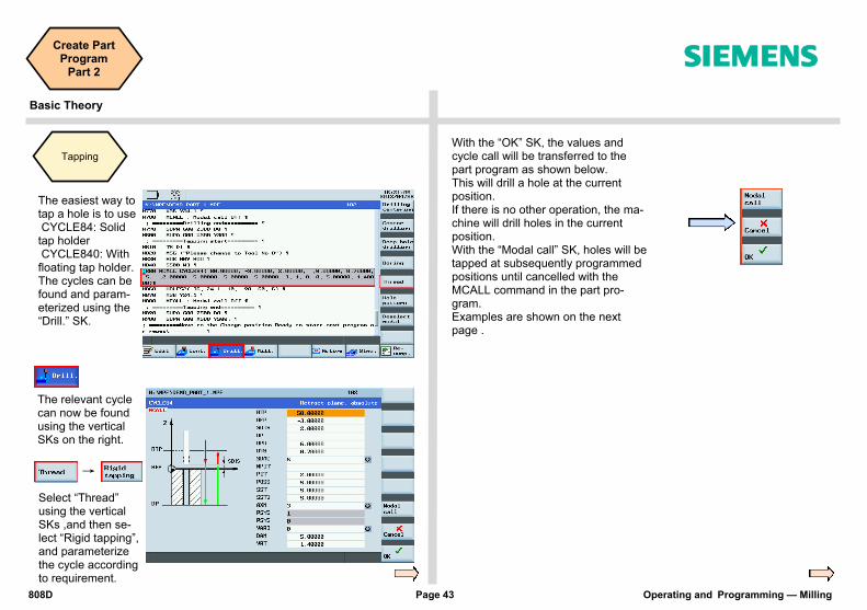
The easiest way to tap a hole is to use CYCLE84: Solid tap holder CYCLE840: With floating tap holder. The cycles can be found and param-eterized using the “Drill.” SK.
The relevant cycle can now be found using the vertical SKs on the right.
Select “Thread” using the vertical SKs ,and then se-lect “Rigid tapping”, and parameterize the cycle according to requirement.
Tapping
With the “OK” SK, the values and cycle call will be transferred to the part program as shown below. This will drill a hole at the current position. If there is no other operation, the ma-chine will drill holes in the current position. With the “Modal call” SK, holes will be tapped at subsequently programmed positions until cancelled with the MCALL command in the part pro-gram. Examples are shown on the next page .
→
Operating and Programming — Milling Page 44 808D
Create Part Program
Part 2 s
Basic Theory
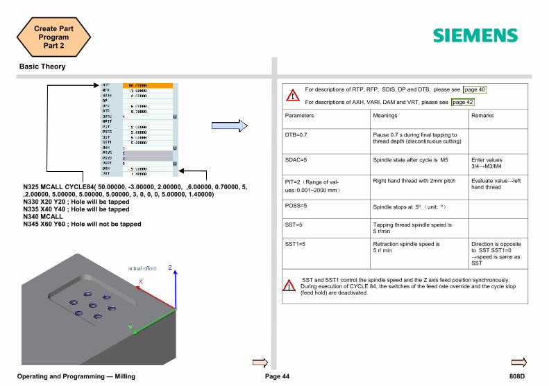
SST and SST1 control the spindle speed and the Z axis feed position synchronously. During execution of CYCLE 84, the switches of the feed rate override and the cycle stop (feed hold) are deactivated.
N325 MCALL CYCLE84( 50.00000, -3.00000, 2.00000, ,6.00000, 0.70000, 5, ,2.00000, 5.00000, 5.00000, 5.00000, 3, 0, 0, 0, 5.00000, 1.40000) N330 X20 Y20 ; Hole will be tapped N335 X40 Y40 ; Hole will be tapped N340 MCALL N345 X60 Y60 ; Hole will not be tapped
For descriptions of RTP, RFP, SDIS, DP and DTB, please see page 40 For descriptions of AXH, VARI, DAM and VRT, please see page 42
Parameters Meanings Remarks
DTB=0.7 Pause 0.7 s during final tapping to thread depth (discontinuous cutting)
SDAC=5 Spindle state after cycle is M5 Enter values 3/4→M3/M4
PIT=2(Range of val-
ues:0.001~2000 mm)
Right hand thread with 2mm pitch Evaluate value→left hand thread
POSS=5 Spindle stops at 5º (unit: º)
SST=5 Tapping thread spindle speed is 5 r/min
SST1=5 Retraction spindle speed is 5 r/ min
Direction is opposite to SST SST1=0 →speed is same as SST
808D Page 45 Operating and Programming — Milling
Create Part Program
Part 2 s
Basic Theory
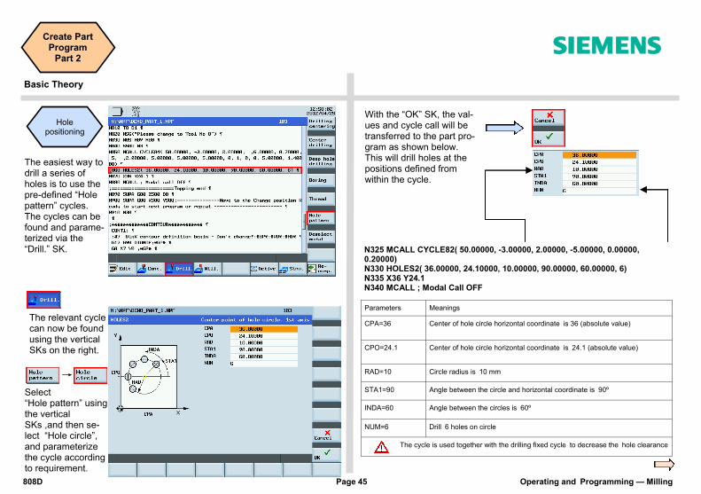
→
The easiest way to drill a series of holes is to use the pre-defined “Hole pattern” cycles. The cycles can be found and parame-terized via the “Drill.” SK.
The relevant cycle can now be found using the vertical SKs on the right.
Select “Hole pattern” using the vertical SKs ,and then se-lect “Hole circle”, and parameterize the cycle according to requirement.
Hole positioning
N325 MCALL CYCLE82( 50.00000, -3.00000, 2.00000, -5.00000, 0.00000, 0.20000) N330 HOLES2( 36.00000, 24.10000, 10.00000, 90.00000, 60.00000, 6) N335 X36 Y24.1 N340 MCALL ; Modal Call OFF
With the “OK” SK, the val-ues and cycle call will be transferred to the part pro-gram as shown below. This will drill holes at the positions defined from within the cycle.
Parameters Meanings
CPA=36 Center of hole circle horizontal coordinate is 36 (absolute value)
CPO=24.1 Center of hole circle horizontal coordinate is 24.1 (absolute value)
RAD=10 Circle radius is 10 mm
STA1=90 Angle between the circle and horizontal coordinate is 90º
INDA=60 Angle between the circles is 60º
NUM=6 Drill 6 holes on circle
The cycle is used together with the drilling fixed cycle to decrease the hole clearance
Operating and Programming — Milling Page 46 808D
Create Part Program
Part 2 s
Basic Theory
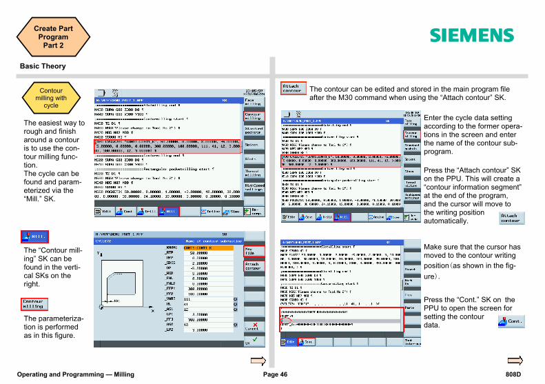
The easiest way to rough and finish around a contour is to use the con-tour milling func-tion. The cycle can be found and param-eterized via the “Mill.” SK.
The “Contour mill-ing” SK can be found in the verti-cal SKs on the right.
The parameteriza-tion is performed as in this figure.
Contour milling with
cycle
Make sure that the cursor has moved to the contour writing
position(as shown in the fig-
ure).
Press the “Cont.” SK on the PPU to open the screen for setting the contour data.
Enter the cycle data setting according to the former opera-tions in the screen and enter the name of the contour sub-program.
Press the “Attach contour” SK on the PPU. This will create a “contour information segment” at the end of the program, and the cursor will move to the writing position automatically.
The contour can be edited and stored in the main program file after the M30 command when using the “Attach contour” SK.

808D Page 47 Operating and Programming — Milling
Create Part Program
Part 2 s
Basic Theory
Enter appropriate start point coordi-nates as in the machining figure and select the correct approach.
Press the “Accept element” SK on the PPU.
Use the arrows on the PPU to select the direction and the shape of the contour milling.
Press the “Accept element” SK on the PPU.
The selected di-rection is shown at the top left side of PPU.
The meanings of the highlighted positions is shown at the bottom of the PPU screen.
When you have opened the screen for setting the contour data, you can make the following settings:
Enter the corre-sponding coordi-nate parameters.
Select different items (SKs) to set the contour until finishing editing the whole shape of the contour.
Press ”accept” SK on PPU to input the contour information in the main program
Operating and Programming — Milling Page 48 808D
Create Part Program
Part 2 s
Basic Theory
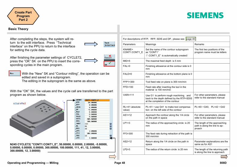
After completing the steps, the system will re-turn to the edit interface. Press “Technical interface” on the PPU to return to the interface for setting the cycle data.
After finishing the parameter settings of CYCLE72, press the ”OK” SK on the PPU to insert the corre-sponding cycles in the main program.
With the “New” SK and “Contour milling”, the operation can be edited and saved in a subprogram. The editing in the subprogram is the same as above.
With the “OK” SK, the values and the cycle call are transferred to the part program as shown below.
N245 CYCLE72( "CONT1:CONT1_E", 50.00000, 0.00000, 2.00000, -5.00000, 5.00000, 0.00000, 0.00000, 300.00000, 100.00000, 111, 41, 12, 3.00000, 300.00000, 12, 3.00000)
For descriptions of RTP, RFP, SDIS and DP, please see page 40
Parameters Meanings Remarks
KNAME= CONT1:CONT1_E
Set the name of the contour subprogram as “CONT1”
(“:CONT1_E” is automatically created)
The first two positions of the program name must be letters
MID=5 The maximal feed depth is 5 mm
FAL=0 Finishing allowance at the contour side is 0 mm
FALD=0 Finishing allowance at the bottom plane is 0 mm
FFP1=300 Tool feed rate on plane is 300 mm/min
FFD=100 Feed rate after inserting the tool in the material is 100 mm/min
VARI=111 Use G1 to perform rough machining, and
back to the depth defined by the RTP+SDIS at the completion of the contour
For other parameters, please refer to the standard manual
RL=41(absolute
value)
PL=41→use G41 to make tool compensa-
tion on the left side of the contour
PL=40→G40, PL=42→G42
AS1=12
Approach the contour along the 1/4 circle on the path in space
For other parameters, please refer to the standard manual
LP1=3 The radius of the approaching circle is 20 mm
The length of the approaching path is along the line to ap-proach
FF3=300 The feed rate during retraction of the path is 300 mm/min
AS2=12 Return along the 1/4 circle on the path in space
Parameter explanations are the same as for AS1
LP2=3 The radius of the return circle is 20 mm The length of the returning path is along the line to approach
808D Page 49 Operating and Programming — Milling
Create Part Program
Part 2 s
Basic Theory
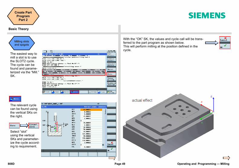
With the “OK” SK, the values and cycle call will be trans-ferred to the part program as shown below. This will perform milling at the position defined in the cycle.
The easiest way to mill a slot is to use the SLOT2 cycle. The cycle can be found and parame-terized via the “Mill.” SK.
The relevant cycle can be found using the vertical SKs on the right.
Select “slot” using the vertical SKs and parameter-ize the cycle accord-ing to requirement.
Milling slots and spigots
Operating and Programming — Milling Page 50 808D
Create Part Program
Part 2 s
Basic Theory
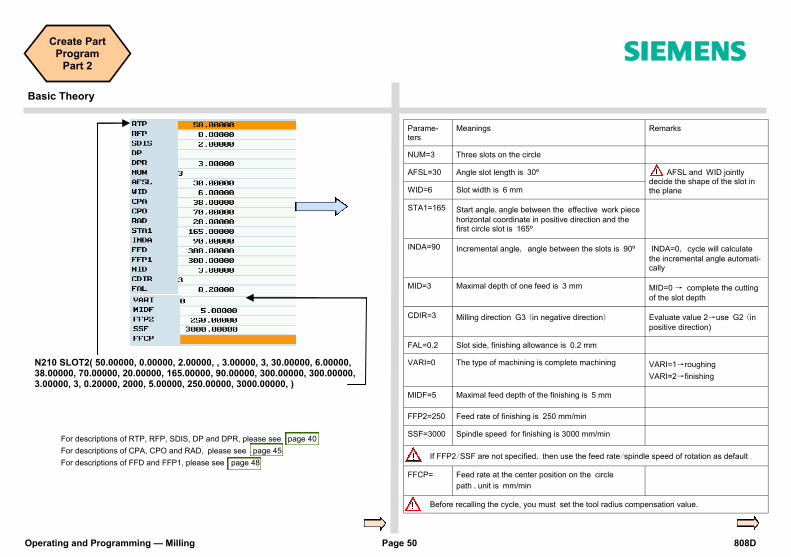
N210 SLOT2( 50.00000, 0.00000, 2.00000, , 3.00000, 3, 30.00000, 6.00000, 38.00000, 70.00000, 20.00000, 165.00000, 90.00000, 300.00000, 300.00000, 3.00000, 3, 0.20000, 2000, 5.00000, 250.00000, 3000.00000, )
Parame-ters
Meanings Remarks
NUM=3 Three slots on the circle
AFSL=30 Angle slot length is 30º AFSL and WID jointly decide the shape of the slot in the plane WID=6 Slot width is 6 mm
STA1=165 Start angle,angle between the effective work piece
horizontal coordinate in positive direction and the first circle slot is 165º
INDA=90 Incremental angle, angle between the slots is 90º INDA=0, cycle will calculate
the incremental angle automati-cally
MID=3 Maximal depth of one feed is 3 mm MID=0 → complete the cutting
of the slot depth
CDIR=3 Milling direction G3 (in negative direction) Evaluate value 2→use G2 (in
positive direction)
FAL=0.2 Slot side, finishing allowance is 0.2 mm
VARI=0 The type of machining is complete machining VARI=1→roughing
VARI=2→finishing
MIDF=5 Maximal feed depth of the finishing is 5 mm
FFP2=250 Feed rate of finishing is 250 mm/min
SSF=3000 Spindle speed for finishing is 3000 mm/min
If FFP2/SSF are not specified, then use the feed rate/spindle speed of rotation as default
FFCP= Feed rate at the center position on the circle
path ,unit is mm/min
Before recalling the cycle, you must set the tool radius compensation value.
For descriptions of RTP, RFP, SDIS, DP and DPR, please see page 40
For descriptions of CPA, CPO and RAD, please see page 45
For descriptions of FFD and FFP1, please see page 48
808D Page 51 Operating and Programming — Milling
Notes
s

Operating and Programming — Milling Page 52 808D
Notes
s

808D Page 53 Operating and Programming — Milling
Simulate Program s
Content SEQUENCE
Module Description This unit describes how to simulate a part program before executing it in AUTO mode.
Module Content
Simulate pro-
gram(Axis do
not move)
Simulate program
(Axis do not
move)
A part program must have been created before it can be tested using “Simulation”.
Step 1
The part program must be opened using the “Program Manager” on PPU.
End

Operating and Programming — Milling Page 54 808D
Simulate Program s
SEQUENCE
Step 2
If the control is not in the correct mode, a message will be displayed at the bottom of the screen.
If this message is displayed at the bottom of the screen, press the “AUTO” mode key on the MCP.
Step 3
Press the “Simu.” SK on the PPU. Press the “CYCLE START” key on the MCP.
Press the “Edit” SK on the PPU to return to the program.
End

808D Page 55 Operating and Programming — Milling
Notes
s

Operating and Programming — Milling Page 56 808D
Notes
s
808D Page 57 Operating and Programming — Milling
Test Program s
Content SEQUENCE
Unit Description This unit describes how to load the program in “AUTO“ mode and test the part program at fixed speed.
Unit Content
Program Execution
Dry Run
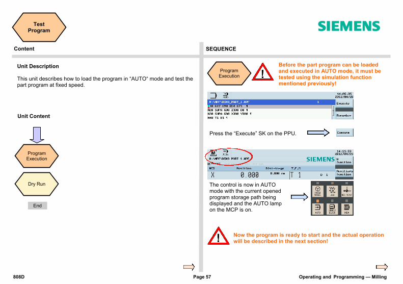
Program Execution
Before the part program can be loaded and executed in AUTO mode, it must be tested using the simulation function mentioned previously!
Press the “Execute” SK on the PPU.
The control is now in AUTO mode with the current opened program storage path being displayed and the AUTO lamp on the MCP is on.
Now the program is ready to start and the actual operation will be described in the next section!
End

Operating and Programming — Milling Page 58 808D
Test Program s
SEQUENCE
Step 1 The data in the “Dry run feedrate” must first be set and checked!
Press the “Offset” key on the PPU.
Press the “Sett. data” SK on the PPU.
Use the traversing key to move to the required position. The position is now highlighted.
Enter the required feedrate in mm/min, enter “2000 ” in the example.
Press the “Input” key of the PPU.
Press the “Machine” key on the PPU.
Press the “Prog. cont.” SK on the PPU.
Make sure the feedrate override on the MCP is 0%.
Press “Door” on the MCP to close the door of the machine. (If you don’t use this function, just close the door in the machine manually.)
Turn the feedrate override gradually to the required value.
Press “CYCLE START” on the MCP to execute the program.
Note: The “DRY” symbol is shown and the “Dry run feedrate” SK is highlighted in blue.
Press the “Back” SK on the PPU.
Before executing the “Dry Run”, please change the offset value appropriately for the real workpiece size in order to avoid cutting the real workpiece during the dry run and avoid unnecessary danger!
Step 2
Press the “Dry run feedrate” SK on the PPU.
Note: The following operation is based on the finished “program execution”
After finishing the dry run, please turn the changed offset back to the original value in order to avoid affecting the actual machining!
Dry Run

808D Page 59 Operating and Programming — Milling
Notes
s

Operating and Programming — Milling Page 60 808D
Notes
s
808D Page 61 Operating and Programming — Milling
Machine Pieces s
Content Basic Theory
Unit Description This unit describes how to use the Time counter function and how to machine pieces and the compensation setting for the tool wear.
Unit Content
Time Coun-ter
PieceMa-chining
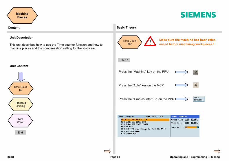
Time Coun-ter
Make sure the machine has been refer-
enced before machining workpieces!
Step 1
Press the “Machine” key on the PPU.
Press the “Auto” key on the MCP.
Press the “Time counter” SK on the PPU.
Tool Wear
End
Operating and Programming — Milling Page 62 808D
Machine Pieces s
SEQUENCE
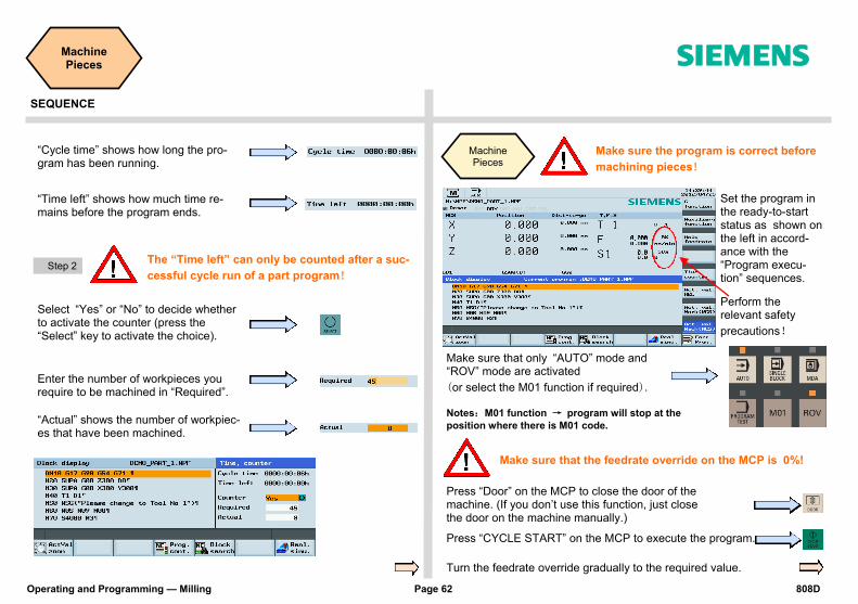
“Cycle time” shows how long the pro-gram has been running.
“Time left” shows how much time re-mains before the program ends.
Step 2
Select “Yes” or “No” to decide whether to activate the counter (press the “Select” key to activate the choice).
Enter the number of workpieces you require to be machined in “Required”.
Machine Pieces
Make sure that only “AUTO” mode and “ROV” mode are activated
(or select the M01 function if required).
Make sure that the feedrate override on the MCP is 0%!
Press “Door” on the MCP to close the door of the machine. (If you don’t use this function, just close the door on the machine manually.)
Turn the feedrate override gradually to the required value.
“Actual” shows the number of workpiec-es that have been machined.
The “Time left” can only be counted after a suc-
cessful cycle run of a part program!
Make sure the program is correct before
machining pieces!
Press “CYCLE START” on the MCP to execute the program.
Set the program in the ready-to-start status as shown on the left in accord-ance with the “Program execu-tion” sequences.
Perform the relevant safety
precautions!
Notes:M01 function → program will stop at the
position where there is M01 code.
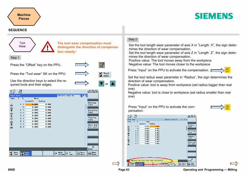
808D Page 63 Operating and Programming — Milling
Machine Pieces s
SEQUENCE
Step 1
Press the “Offset” key on the PPU.
Press the “Tool wear” SK on the PPU.
Use the direction keys to select the re-quired tools and their edges. or
Step 2
Set the tool length wear parameter of axis X in ”Length X”, the sign deter-mines the direction of wear compensation. Set the tool length wear parameter of axis Z in ”Length Z”, the sign deter-mines the direction of wear compensation. Positive value: The tool moves away from the workpiece Negative value: The tool moves closer to the workpiece
Set the tool radius wear parameter in “Radius”, the sign determines the direction of wear compensation. Positive value: tool is away from workpiece (set radius bigger than real one) Negative value: tool is close to workpiece (set radius smaller than real one)
Press “Input” on the PPU to activate the compensation.
Press “Input” on the PPU to activate the com-pensation.
Tool Wear
The tool wear compensation must distinguish the direction of compensa-
tion clearly!

Operating and Programming — Milling Page 64 808D
Notes
s

808D Page 65 Operating and Programming — Milling
Program Restart s
Content SEQUENCE
Unit Description This unit describes how to restart the part program after a tool has been changed due to damage, or remachining has to be performed.
Unit Content
Block Search
Block Search
Press the “Machine” key on the PPU.
Press the “Auto” key on the MCP.
Press the “Block search” SK on the PPU.
Note: The cursor can be moved to the required program block with the traversing keys.
Press the “To end point” SK on the PPU. (can also press “To contour” if required)
Press the “Interr. point” SK on the PPU and the cursor will move to the last interrupted program line.
Note: The “To con-tour” and “To end point” functions. “To contour”: The program will continue from the line before the breakpoint. “To end point”: The program will continue from the line with the breakpoint.
End
Operating and Programming — Milling Page 66 808D
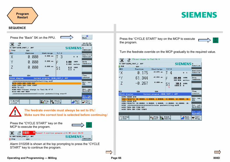
Program Restart s
SEQUENCE
Press the “Back” SK on the PPU.
The feedrate override must always be set to 0%!
Make sure the correct tool is selected before continuing!
Press the “CYCLE START” key on the MCP to execute the program.
Press the “CYCLE START” key on the MCP to execute the program.
Turn the feedrate override on the MCP gradually to the required value.
Alarm 010208 is shown at the top prompting to press the “CYCLE START” key to continue the program.
808D Page 67 Operating and Programming — Milling
Notes
s

Operating and Programming — Milling Page 68 808D
Notes
s

808D Page 69 Operating and Programming — Milling
Additional Information
Part 1 s
Content SEQUENCE
Unit Description This unit describes how to perform simple tasks on the machine and provides some additional information which may be required to operate the machine correctly.
Unit Content
RS232 +
USB
Help
Manual face
milling
R parameters
Time change
Save data
Gear change
RS232 +
USB
RS232 is used to transfer the programs to and from the NC.
Step 1
Adjust the parameter settings on the PPU to match the settings of the communication SW on the PC.
Press “Program Manager” on the PPU.
Press the “RS232” SK on the PPU.
Press the “Settings” SK on the PPU.
Adjust the parameters in “Communication settings” to match the settings of communication SW on PC.
Press the “Save” SK on the PPU.
Press the “Back” SK on the PPU.
It is recommended to use the “SINUCOM PCIN” communication SW provided by Siemens to transfer the standard program.
End

Operating and Programming — Milling Page 70 808D
Additional Information
Part 1 s
SEQUENCE
Step 2 Transfer a part program to a PC from the PPU.
Press the “NC” SK on the PPU.
Press the “RS232” SK on the PPU.
Press the “Send” SK on the PPU.
Check the interface setting and start the communication software to receive the program on PC.
(Press ”Receive Data” on SINUCOM PCIN to start the receive function.)
Use “Cursor + Select” to select the required part program. The selected program will be highlighted.
The PPU will display a window showing the progress of the transfer.
If there is a problem during transfer of the part program, a window will be displayed.
You can continue sending the part program.
Press the “OK” SK on the PPU.
Or you can abort the sending of the part program
Press the “Cancel” SK on the PPU.
Step 3 Transfer a part program to the PPU from a PC.
Press the “RS232” SK on the PPU.
Press the “Accept” SK on the PPU.
The PPU will display a window showing the progress of the transfer.
Press “Program Manager” on the PPU.
Check the interface setting and start the communication software to send the program from PC.
(Press ”Send Data” on SINUCOM PCIN to send data.)
Press the “Copy” SK on the PPU.
+

808D Page 71 Operating and Programming — Milling
Additional Information
Part 1 s
SEQUENCE
Use the “Copy” and “Paste” SKs to transfer the part program from NC to USB.
Press the “USB” SK on the PPU.
Press the “NC” SK on the PPU.
Press the “Copy” SK on the PPU.
Press the “Paste” SK on the
Step 5 Use the “Copy” and “Paste” SKs to transfer the part program from USB to NC.
Press the “NC” SK on the PPU.
Press the “USB” SK on the PPU.
Press the “Copy” SK on the PPU.
Press the “Paste” SK on the
Help
The PPU has an online help which shows the contents of standard docu-ments.
Press the “Help” key on the PPU.
Press the “Cur. Topic” SK on the PPU.
The help information related to the current topic will be shown on screen.
Press the “OEM Manual” SK on the PPU.
The online help manual of the OEM will be shown on the screen.
Press the “TOC” SK on the PPU.
The online help from the Siemens manual will be shown.
Connect a USB device with sufficient memory to the USB interface on the PPU.
Connect the USB device with the stored target programs to the USB interface on the PPU.
“USB” is used to transfer the programs to and from the NC.
Step 4
Use “Cursor + Select” to select the required part program. The selected program will be highlighted.
Use “Cursor + Select” to select the required part program. The selected program will be highlighted.
+
+
Operating and Programming — Milling Page 72 808D
Additional Information
Part 1 s
SEQUENCE
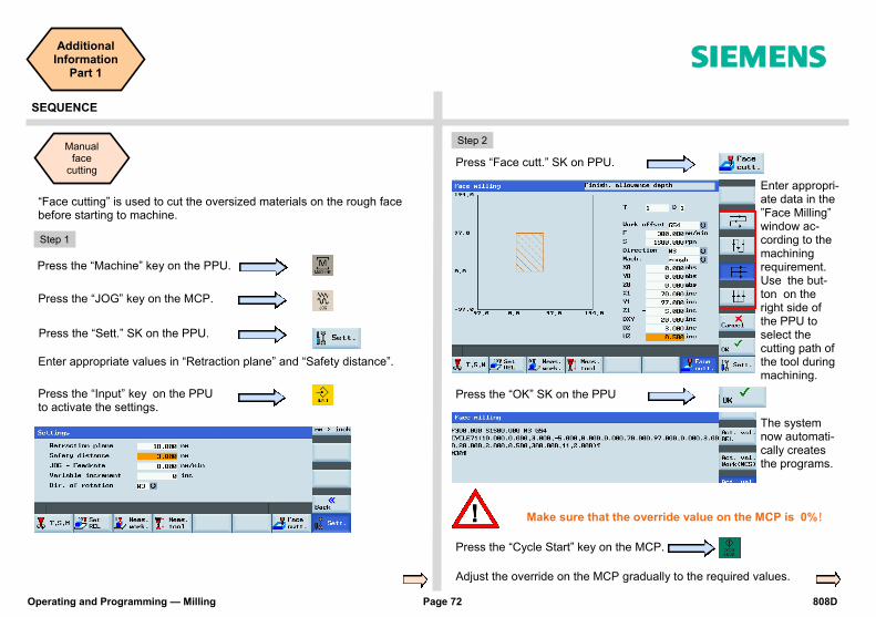
“Face cutting” is used to cut the oversized materials on the rough face before starting to machine.
Manual face
cutting
Step 1
Press the “Machine” key on the PPU.
Press “Face cutt.” SK on PPU.
Press the “Sett.” SK on the PPU.
Enter appropriate values in “Retraction plane” and “Safety distance”.
Press the “OK” SK on the PPU
Press the “JOG” key on the MCP.
Make sure that the override value on the MCP is 0%!
Adjust the override on the MCP gradually to the required values.
Press the “Input” key on the PPU to activate the settings.
Enter appropri-ate data in the ”Face Milling” window ac-cording to the machining requirement. Use the but-ton on the right side of the PPU to select the cutting path of the tool during machining.
Press the “Cycle Start” key on the MCP.
The system now automati-cally creates the programs.
Step 2
808D Page 73 Operating and Programming — Milling
Additional Information
Part 1 s
SEQUENCE
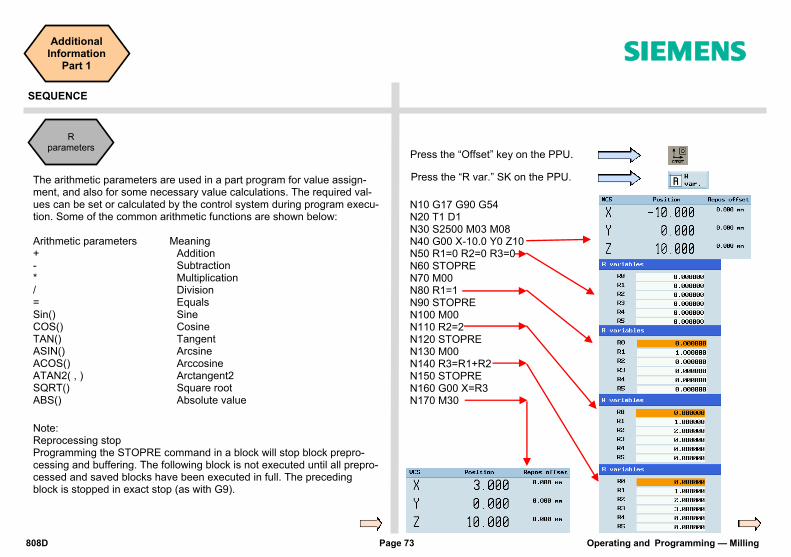
R parameters
N10 G17 G90 G54 N20 T1 D1 N30 S2500 M03 M08 N40 G00 X-10.0 Y0 Z10 N50 R1=0 R2=0 R3=0 N60 STOPRE N70 M00 N80 R1=1 N90 STOPRE N100 M00 N110 R2=2 N120 STOPRE N130 M00 N140 R3=R1+R2 N150 STOPRE N160 G00 X=R3 N170 M30
The arithmetic parameters are used in a part program for value assign-ment, and also for some necessary value calculations. The required val-ues can be set or calculated by the control system during program execu-tion. Some of the common arithmetic functions are shown below: Arithmetic parameters Meaning + Addition - Subtraction * Multiplication / Division = Equals Sin() Sine COS() Cosine TAN() Tangent ASIN() Arcsine ACOS() Arccosine ATAN2( , ) Arctangent2 SQRT() Square root ABS() Absolute value
Note: Reprocessing stop Programming the STOPRE command in a block will stop block prepro-cessing and buffering. The following block is not executed until all prepro-cessed and saved blocks have been executed in full. The preceding block is stopped in exact stop (as with G9).
Press the “Offset” key on the PPU.
Press the “R var.” SK on the PPU.

Operating and Programming — Milling Page 74 808D
Additional Information
Part 1 s
SEQUENCE
Time change
You can change the time on the control if required when the clocks changes from summer time to winter time.
“Save data” enables the complete system to be backed up on the system CF card so that there is a system backup available to the operator.
Press the “Date time” SK on the PPU.
Press the “OK” SK on the PPU.
Make sure the password is set to the “CUSTOMER” access level.
Press “Shift” and “Alarm” on the PPU simul-taneously.
Enter a new “Date” and “Time”.
Save data
Press the “Save data” SK on the PPU.
Make sure the password is set to the “CUSTOMER” access level.
Press “Shift” and “Alarm” on the PPU simultaneously.
+
Press the “Cancel” SK on the PPU to abort the operation.
+

808D Page 75 Operating and Programming — Milling
Additional Information
Part 1 s
SEQUENCE
Gear stages M40, M41, M42, M43, M44 and M45 are available. M40 Automatic gear selection M41 Gear stage 1 M42 Gear stage 2 M43 Gear stage 3 M44 Gear stage 4 M45 Gear stage 5 Example: The machine tool manufacturer specifies a speed range for each gear stage:
S0...500 Gear stage 1 → M41
S400..1200 Gear stage 2 → M42
S1000..2000 Gear stage 3 → M43
If the operator is manually selecting the gear stage in the part program, it is the operator’s responsibility to select the correct gear stage according to the required speed.
Press the “OK” SK on the PPU.
Gear change
When a machine has a manual gearbox on the spindle, it is the responsi-bility of the operator to change gear at the correct place in the part pro-gram.
If the machine tool manufacturer has fitted an automatic gearbox, the following M-codes can be used to change gear in the part program:
While the control is saving data to the system, do not operate or switch off the control!

Operating and Programming — Milling Page 76 808D
Notes
s

808D Page 77 Operating and Programming — Milling
Additional Information
Part 2 s
Content SEQUENCE
Unit Description This unit describes how to perform simple tasks on the machine and provides some additional information which may be required to operate the machine correctly. Part 2
Unit Content
MDA
M/H function
Subpro-gram
Polar coordinates
Additive workpiece
offsets
Coordinate rotation
ROT AROT
Scaling
MDA
In MDA mode, you can enter and execute single and multiple lines of NC codes.
Use MDA to move the axis to a fixed position.
Press the “MDA” key on the
Enter correct NC code to move the axis to the required position.
Program jump
Press the “Delete file” SK on the PPU.
Calculator
Press “CYCLE START” on the MCP to execute the MDA program.
Make sure the feedrate override on the MCP is at 0%!
Program skip
Turn the feedrate override on the MCP gradually to the required value.
Program example
Press the “Machine” key on the PPU.
End
Operating and Programming — Milling Page 78 808D
Additional Information
Part 2 s
SEQUENCE
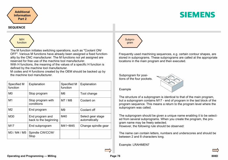
The M function initiates switching operations, such as "Coolant ON/OFF". Various M functions have already been assigned a fixed function-ality by the CNC manufacturer. The M functions not yet assigned are reserved for free use of the machine tool manufacturer. With H functions, the meaning of the values of a specific H function is defined by the machine tool manufacturer. M codes and H functions created by the OEM should be backed up by the machine tool manufacturer.
Subpro-gram
Frequently used machining sequences, e.g. certain contour shapes, are stored in subprograms. These subprograms are called at the appropriate locations in the main program and then executed.
Subprogram for posi-tions of the four pockets. Example
The structure of a subprogram is identical to that of the main program, but a subprogram contains M17 - end of program in the last block of the program sequence. This means a return to the program level where the subprogram was called.
The subprogram should be given a unique name enabling it to be select-ed from several subprograms. When you create the program, the pro-gram name may be freely selected. However, the following rule should be observed: The name can contain letters, numbers and underscores and should be between 2 and 8 characters long.
Example: LRAHMEN7
M/H function
Specified M function
Explanation
M0 Stop program
M1 Stop program with conditions
M2 End program
M30 End program and back to the beginning
M17 End subprogram
M3 / M4 / M5 Spindle CW/CCW/Stop
Specified M function
Explanation
M6 Tool change
M7 / M8 Coolant on
M9 Coolant off
M40 Select gear stage automatically
M41~M45 Change spindle gear
808D Page 79 Operating and Programming — Milling
Additional Information
Part 2 s
SEQUENCE
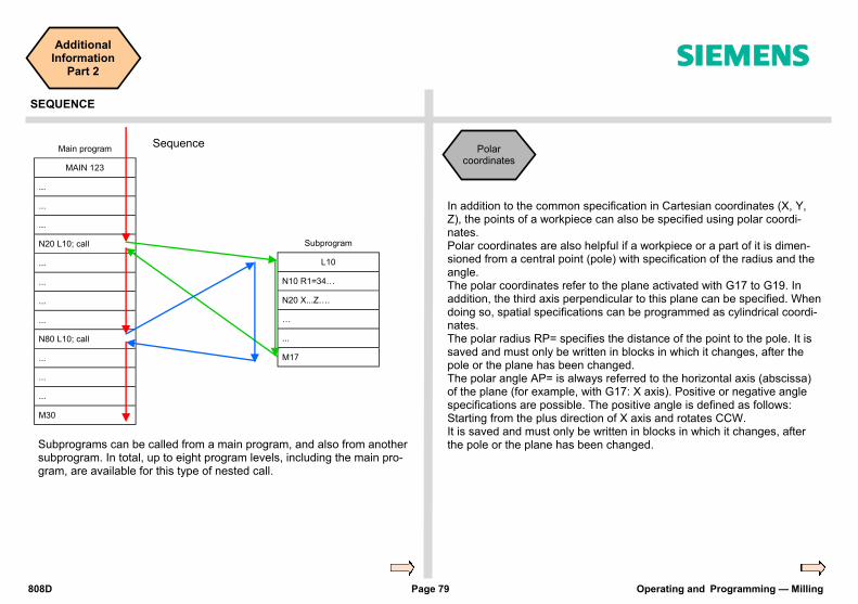
Main program
MAIN 123
...
...
...
N20 L10; call
...
...
...
...
N80 L10; call
...
...
...
M30
Subprogram
L10
N10 R1=34…
N20 X...Z….
…
...
M17
Sequence
Subprograms can be called from a main program, and also from another subprogram. In total, up to eight program levels, including the main pro-gram, are available for this type of nested call.
In addition to the common specification in Cartesian coordinates (X, Y, Z), the points of a workpiece can also be specified using polar coordi-nates. Polar coordinates are also helpful if a workpiece or a part of it is dimen-sioned from a central point (pole) with specification of the radius and the angle. The polar coordinates refer to the plane activated with G17 to G19. In addition, the third axis perpendicular to this plane can be specified. When doing so, spatial specifications can be programmed as cylindrical coordi-nates. The polar radius RP= specifies the distance of the point to the pole. It is saved and must only be written in blocks in which it changes, after the pole or the plane has been changed. The polar angle AP= is always referred to the horizontal axis (abscissa) of the plane (for example, with G17: X axis). Positive or negative angle specifications are possible. The positive angle is defined as follows: Starting from the plus direction of X axis and rotates CCW. It is saved and must only be written in blocks in which it changes, after the pole or the plane has been changed.
Polar coordinates
Operating and Programming — Milling Page 80 808D
Additional Information
Part 2 s
Basic Theory
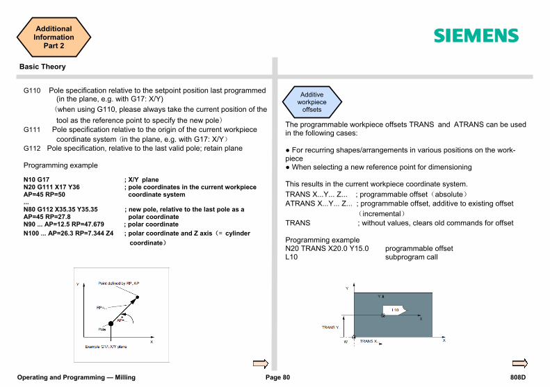
The programmable workpiece offsets TRANS and ATRANS can be used in the following cases: ● For recurring shapes/arrangements in various positions on the work-piece ● When selecting a new reference point for dimensioning This results in the current workpiece coordinate system.
TRANS X...Y... Z... ; programmable offset(absolute)
ATRANS X...Y... Z... ; programmable offset, additive to existing offset
(incremental)
TRANS ; without values, clears old commands for offset Programming example N20 TRANS X20.0 Y15.0 programmable offset L10 subprogram call
G110 Pole specification relative to the setpoint position last programmed (in the plane, e.g. with G17: X/Y)
(when using G110, please always take the current position of the
tool as the reference point to specify the new pole) G111 Pole specification relative to the origin of the current workpiece
coordinate system (in the plane, e.g. with G17: X/Y)
G112 Pole specification, relative to the last valid pole; retain plane Programming example
N10 G17 ; X/Y plane N20 G111 X17 Y36 ; pole coordinates in the current workpiece AP=45 RP=50 coordinate system ... N80 G112 X35.35 Y35.35 ; new pole, relative to the last pole as a AP=45 RP=27.8 polar coordinate N90 ... AP=12.5 RP=47.679 ; polar coordinate
N100 ... AP=26.3 RP=7.344 Z4 ; polar coordinate and Z axis(= cylinder
coordinate)
Additive workpiece
offsets

808D Page 81 Operating and Programming — Milling
Additional Information
Part 2 s
Basic Theory
The programmable rotation ROT, AROT can be used: The rotation is performed in the current plane G17, G18 or G19 using the value of RPL=...specified in degrees. ROT RPL=... ; programmable rotation offset (absolute). AROT RPL=… ; programmable offset, additive to existing offset (incremental) ROT ; without values, clears old commands for offset N10 G17 N20 AROT RPL=45 additive 45 degree rotation L10 subprogram call
Coordinate rotation
ROT AROT
A scale factor can be programmed for all axes with SCALE, ASCALE. The path is enlarged or reduced by this factor in the specified axis. The cur-rently set coordinate system is used as the reference for the scale change. SCALE X...Y... Z... ; programmable rotation offset (absolute) ASCALE X...Y... Z... ; programmable offset, additive to existing offset (incremental) If a program contains SCALE or ASCALE, this must be programmed in a separate block. Programming example N10 G17
N20 SCALE X2.0 Y2.0 ;contour is enlarged two times in X and Y
L10 subprogram call
Scaling
Operating and Programming — Milling Page 82 808D
Additional Information
Part 2 s
Basic Theory
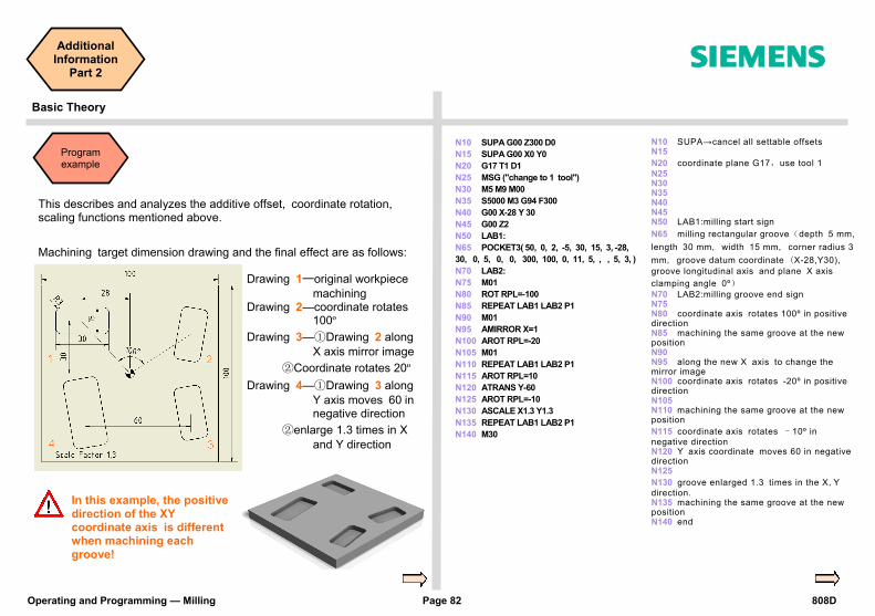
This describes and analyzes the additive offset, coordinate rotation, scaling functions mentioned above.
Machining target dimension drawing and the final effect are as follows:
Drawing 1—original workpiece
machining Drawing 2—coordinate rotates
100º
Drawing 3—①Drawing 2 along X axis mirror image
②Coordinate rotates 20º
Drawing 4—①Drawing 3 along Y axis moves 60 in negative direction
②enlarge 1.3 times in X and Y direction
N10 SUPA G00 Z300 D0
N15 SUPA G00 X0 Y0
N20 G17 T1 D1
N25 MSG ("change to 1 tool")
N30 M5 M9 M00
N35 S5000 M3 G94 F300
N40 G00 X-28 Y 30
N45 G00 Z2
N50 LAB1:
N65 POCKET3( 50, 0, 2, -5, 30, 15, 3, -28,
30, 0, 5, 0, 0, 300, 100, 0, 11, 5, , , 5, 3, )
N70 LAB2:
N75 M01
N80 ROT RPL=-100
N85 REPEAT LAB1 LAB2 P1
N90 M01
N95 AMIRROR X=1
N100 AROT RPL=-20
N105 M01
N110 REPEAT LAB1 LAB2 P1
N115 AROT RPL=10
N120 ATRANS Y-60
N125 AROT RPL=-10
N130 ASCALE X1.3 Y1.3
N135 REPEAT LAB1 LAB2 P1
N140 M30
N10 SUPA→cancel all settable offsets N15
N20 coordinate plane G17,use tool 1
N25 N30 N35 N40 N45 N50 LAB1:milling start sign
N65 milling rectangular groove(depth 5 mm,
length 30 mm, width 15 mm, corner radius 3
mm, groove datum coordinate (X-28,Y30),
groove longitudinal axis and plane X axis
clamping angle 0º)
N70 LAB2:milling groove end sign N75 N80 coordinate axis rotates 100º in positive direction N85 machining the same groove at the new position N90 N95 along the new X axis to change the mirror image N100 coordinate axis rotates -20º in positive direction N105 N110 machining the same groove at the new position
N115 coordinate axis rotates –10º in
negative direction N120 Y axis coordinate moves 60 in negative direction N125
N130 groove enlarged 1.3 times in the X,Y
direction. N135 machining the same groove at the new position N140 end
In this example, the positive direction of the XY coordinate axis is different when machining each groove!
Program example
808D Page 83 Operating and Programming — Milling
Additional Information
Part 2 s
Basic Theory
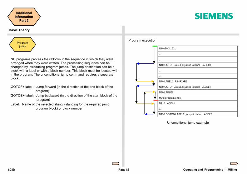
NC programs process their blocks in the sequence in which they were arranged when they were written. The processing sequence can be changed by introducing program jumps. The jump destination can be a block with a label or with a block number. This block must be located with-in the program. The unconditional jump command requires a separate block.
GOTOF+ label:Jump forward (in the direction of the end block of the
program)
GOTOB+ label:Jump backward (in the direction of the start block of the
program)
Label: Name of the selected string (standing for the required jump
program block) or block number
N10 G0 X...Z...
...
...
N40 GOTOF LABEL0; jumps to label LABEL0
...
...
N70 LABEL0: R1=R2+R3
N80 GOTOF LABEL1; jumps to label LABEL1
N90 LABLE2:
M30; program ends
N110 LABEL1:
...
N130 GOTOB LABEL2 ;jumps to label LABEL2
Program execution
Unconditional jump example
Program jump
Operating and Programming — Milling Page 84 808D
Additional Information
Part 2 s
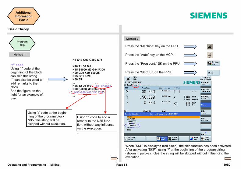
Using “;” code at the begin-ning of the program block N95, this string will be skipped without execution.
Using “;” code to add a remark to the N85 func-tion, without any influence on the execution.
。
“;” code Using “;” code at the beginning of the block can skip this string. “;” can also be used to add remarks to the block. See the figure on the right for an example of use.
Method 1
Method 2
Press the “Machine” key on the PPU.
Press the “Auto” key on the MCP.
Press the “Prog cont.” SK on the PPU.
Press the “Skip” SK on the PPU.
When ”SKP” is displayed (red circle), the skip function has been activated. After activating “SKP”, using “/” at the beginning of the program string (shown in purple circle), the string will be skipped without influencing the execution.
Program skip
N5 G17 G90 G500 G71 N10 T1 D1 M6 N15 S5000 M3 G94 F300 N20 G00 X50 Y50 Z5 N25 G01 Z-20 N30 Z5 ... N85 T2 D1 M6 ; Tool change N90 S5000 M3 G94 F300 ; N95 G00 X60 Y55 Z10 ...
Basic Theory

808D Page 85 Operating and Programming — Milling
Additional Information
Part 2 s
Basic Theory SEQUENCE
You can use the calculator to calculate contour elements, values in the program editor, tool offsets and workpiece offsets and enter the results on the screen.
Press the “=“ SK on the PPU.
Calculator Press this SK to delete the contents in the calculator.
Press this SK to exit the calculator screen.
Use this SK to accept the input and write the values to the required position. If the input field is already occupied by a value, the calculator will take this value into the input line. Use the “Accept” SK to enter the result in the input field at the current cursor position of the part program editor. The calcu-lator will then close automatically.

Operating and Programming — Milling Page 86 808D
Notes
s
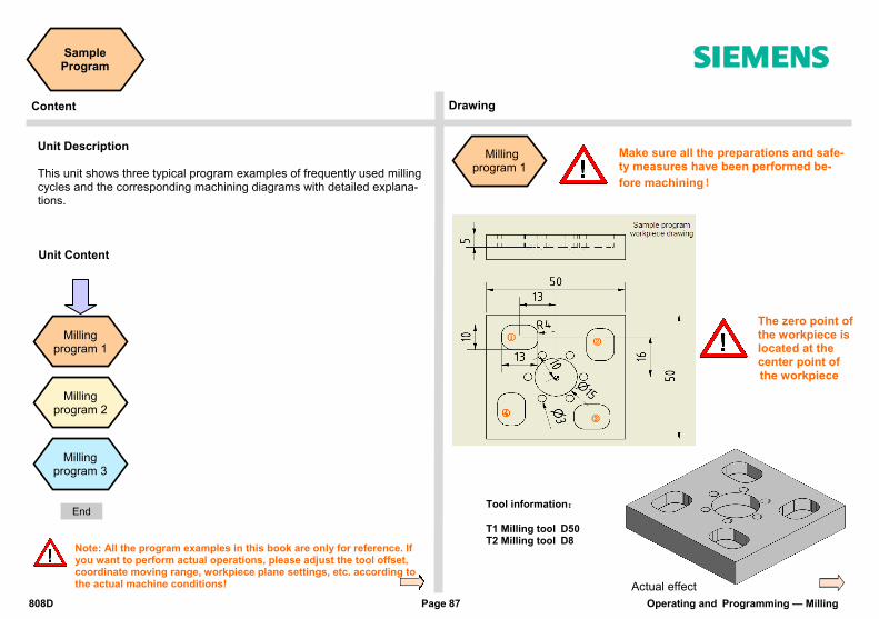
808D Page 87 Operating and Programming — Milling
Sample Program s
Content Drawing
Unit Description This unit shows three typical program examples of frequently used milling cycles and the corresponding machining diagrams with detailed explana-tions.
Unit Content
Milling program 1
Milling program 2
Milling program 1
Make sure all the preparations and safe-ty measures have been performed be-
fore machining!
Tool information: T1 Milling tool D50 T2 Milling tool D8
Actual effect
The zero point of the workpiece is located at the center point of
the workpiece
Milling program 3
Note: All the program examples in this book are only for reference. If you want to perform actual operations, please adjust the tool offset, coordinate moving range, workpiece plane settings, etc. according to the actual machine conditions!
End
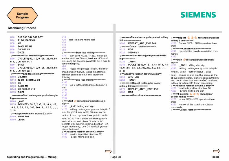
Operating and Programming — Milling Page 88 808D
Sample Program s
N10 G17 G90 G54 G60 ROT
N20 T1 D1; FACEMILL
N30 M6
N40 S4000 M3 M8
N50 G0 X-40 Y0
N60 G0 Z2
; ========Start face milling=========
N70 CYCLE71( 50, 1, 2, 0, -25, -25, 50, 50,
0, 1, , , 0, 400, 11, )
N80 S4500
N90 CYCLE71( 50, 1, 2, 0, -25, -25, 50, 50,
0, 1, , , 0, 400, 32, )
; ========End face milling==========
N100 G0 Z100
N110 T2 D1 ; ENDMILL D8
N120 M6
N130 S4000 M3
N140 M8 G0 X-13 Y16
N150 G0 Z2
; ========Start rectangular pocket rough-
ing==========
N160 _ANF:
N170 POCKET3( 50, 0, 2, -5, 13, 10, 4, -13,
16, 0, 5, 0.1, 0.1, 300, 200, 2, 11, 2.5, , , ,
2, 2)
; ==Adaptive rotation around Z axis==
N180 AROT Z90
N190 _END:
N10 N20 tool 1 is plane milling tool N30 N40 N50 N60 ; =========Start face milling========
N70 start point (X-25,Y-25), the length
and the width are 50 mm, feedrate 400 mm/min, along the direction parallel to the X axis to perform roughing. N80 N90 repeat the process in N80 , the differ-
ence between the two:along the alternate
direction parallel to the X axis to perform finishing ; =========End face milling========= N100 N110 tool 2 is face milling tool, diameter 8 mm N120 N130 N140 N150
; ===Start ① rectangular pocket rough-
ing=== N160 _ANF: Milling start sign
N170 milling rectangular groove (depth 5
mm, length13 mm, width 10 mm, corner
radius 4 mm, groove base point coordi-
nate (X-13,Y16), angle between groove
vertical axis and plane X axis is 0º), feedrate 300 mm/min, milling direction G2, rough machining, use G1 vertical groove center to insert. ; ==Adaptive rotation around Z axis== N180 rotation in positive direction 90º N190 _END: Milling end sign
; =======Repeat rectangular pocket milling
3 times==========
N200 REPEAT _ANF _END P=3
; ======Cancel rotation=======
N210 ROT
N220 S4500 M3
; ========Start rectangular pocket finish-
ing=========
N230 _ANF1:
N240 POCKET3( 50, 0, 2, - 5, 13, 10, 4, -13,
16, 0, 2.5, 0.1, 0.1, 300, 200, 2, 2, 2.5, , , ,
2, 2)
; ==Adaptive rotation around Z axis==
N250 AROT Z90
N260 _END1:
; ========Repeat rectangular pocket
milling 3 times=========
N270 REPEAT _ANF1 _END1 P=3
N280 ROT
; ========Cancel rotation=========
; ====Repeat ② ③ ④ rectangular pocket
milling 3 times===== N200 Repeat N160 ~ N190 operation three times ; =======Cancel rotation========= N210 cancel all the coordinate rotation com-mands N220
; ===Start ① rectangular pocket finish-
ing=== N230 _ANF1: Milling start sign
N240 milling rectangular groove (depth、
length、width、corner radius、base
point、corner angles are the same as the
above parameters), plane feedrate300 mm/min, depth direction feedrate200 mm/min, milling direction G2, finish machining. ; ==Adaptive rotation around Z axis=== N250 rotation in positive direction 90º N260 _END1: Milling end sign
; ====Finishing ② ③ ④ rectangular
pocket milling ===== N270 repeat N230~N260 operation three times N280 cancel all the coordinate rotation commands ; =====Cancel rotation===========
Machining Process
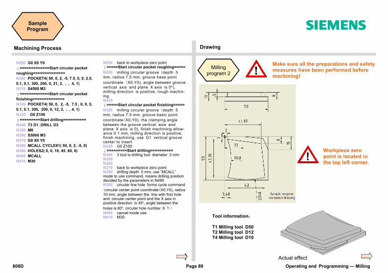
808D Page 89 Operating and Programming — Milling
Sample Program s
Machining Process
N290 G0 X0 Y0
; =============Start circular pocket
roughing==============
N300 POCKET4( 50, 0, 2, -5, 7.5, 0, 0, 2.5,
0.1, 0.1, 300, 200, 0, 21, 2, , , 4, 1)
N310 S4500 M3
; =============Start circular pocket
finishing==============
N320 POCKET4( 50, 0, 2, -5, 7.5 , 0, 0, 5,
0.1, 0.1, 300, 200, 0, 12, 2, , , 4, 1)
N330 G0 Z100
; =========Start drilling==========
N340 T3 D1 ;DRILL D3
N350 M6
N360 S5000 M3
N370 G0 X0 Y0
N380 MCALL CYCLE81( 50, 0, 2, -5, 0)
N390 HOLES2( 0, 0, 10, 45, 60, 6)
N400 MCALL
N410 M30
N290 back to workpiece zero point ; =====Start circular pocket roughing=====
N300 milling circular groove (depth 5
mm, radius 7.5 mm, groove base point
coordinate (X0,Y0), angle between groove
vertical axis and plane X axis is 0º), milling direction is positive, rough machin-ing. N310 ; =====Start circular pocket finishing=====
N320 milling circular groove (depth 5
mm, radius 7.5 mm, groove basic point
coordinate(X0,Y0), the clamping angle
between the groove vertical axis and plane X axis is 0), finish machining allow-ance 0.1 mm, milling direction is positive, finish machining, use G1 vertical groove center to insert. N330 G0 Z100 ; =========Start drilling========== N340 3 tool is drilling tool diameter 3 mm N350 N360 N370 back to workpiece zero point N380 drilling depth 5 mm, use ”MCALL” mode to use command, means drilling position decided by the parameters in N490 N390 circular line hole forms cycle command
(circular center point coordinate(X0,Y0), radius 10 mm, angle between the line with first hole and circular center point and the X axis in positive direction is 45º, angle between the
holes is 60º, circular hole number 6 个)
N400 cancel mode use N410 M30
Make sure all the preparations and safety measures have been performed before machining!
Actual effect
Workpiece zero point is located in the top left corner.
Tool information: T1 Milling tool D50 T2 Milling tool D12 T4 Milling tool D10
Drawing
Milling program 2

Operating and Programming — Milling Page 90 808D
Sample Program s
N10 G17 G90 G60 G54
N20 T1 D1 ;FACEMILL D50
N30 M6
N40 S3500 M3
N50 G0 X0 Y0
N60 G0 Z2
; =======Start face milling========
N70 CYCLE71( 50, 1, 2, 0, 0, 0, 50, -50 , ,
1, 40, , 0.1, 300, 11, )
N80 S4000 M3
N90 CYCLE71( 50, 0.1, 2, 0, 0, 0, 50, -50 ,
, 1, 40, , 0, 250, 32, )
; ======Start contour milling======
N100 T2 D2 ;END MILL
N110 M6
N120 S3500 M6
N130 CYCLE72( "CON1:CON1_E", 50, 0, 2,
-5, 2, 0.1, 0.1, 300, 300, 11, 42, 1, 4, 300, 1, 4)
; =======Start path milling with radius
compensation ========
N140 T4 D1 ;ENDMILL D10
N150 M6
N160 S4000 M3
N170 G0 X55 Y-15
N180 G0 Z2
N190 G1 F300 Z-8
N200 G42 G1 Y-15 X50
N210 G1 X44 Y-2 RND=2
N220 G1 Y0 X 22
N230 G40 Y30
N240 M30
N10 N20 tool 1 is milling tool, diameter 50 mm N30 N40 N50 back to workpiece zero point N60 ; =========Start face milling======
N70 start point (X0,Y0), the length and the width are 50 mm, feedrate 300 mm/min, finishing allowance 0.1 mm, along the direction parallel to the X axis to perform the rough machining N80
N90 start point (X0,Y0), the length and the width are 50 mm, feedrate 250 mm/min, finish-ing allowance 0, along the direction parallel to the X axis to perform the finish machining ; =====Start contour milling======= N100 tool 2 is milling tool N110 N120 N130 contour cutting depth 5 mm, all finishing allowances 0.1 mm, the feedrate of surface machining and cutting direction 300 mm/min, use G42 to activate the compensation, use G1 to do rough machining, approaching path is along a straight line, length 4 mm, the parame-ters of feedrate/path/length in retraction and approach are equal. ; ====Start path milling with radius com-pensation === N140 tool 4 is face milling tool, diameter 10 mm N150 N160 N170 N180 N190 N200 G42 activate tool radius compensation
N210 starts from (X44,Y-2) insert a reverse circle, radius is 2 mm
N220 (X22,Y0) is the reverse circle point N230 G40 cancel tool radius compensation N240
;*************CONTOUR************ CON1: ;#7__DlgK contour definition begin - Don't change!;*GP*;*RO*;*HD* G17 G90 DIAMOF;*GP* G0 X3 Y3 ;*GP* G2 X3.27 Y-40.91 I=AC(-52.703) J=AC(-19.298) ;*GP* G3 X46.27 Y-47 I=AC(38.745) J=AC(54.722) ;*GP* G1 X42 Y-8 ;*GP* X3 Y3 ;*GP* ;CON,0,0.0000,4,4,MST:0,0,AX:X,Y,I,J ;*GP*;*RO*;*HD* ;S,EX:3,EY:3;*GP*;*RO*;*HD* ;ACW,DIA:0/35,EX:3.27,DEY:-43.91,RAD:60;*GP*;*RO*;*HD* ;ACCW,DIA:0/35,DEX:43,EY:-47,RAD:102;*GP*;*RO*;*HD* ;LA,EX:42,EY:-8;*GP*;*RO*;*HD* ;LA,EX:3,EY:3;*GP*;*RO*;*HD* ;#End contour definition end - Don't change!;*GP*;*RO*;*HD* CON1_E:;****** CONTOUR ENDS*******
This program is additional descrip-tion information created by the system automatically after finishing the programming of the rough cut-ting CYCLE72 and does not affect the system execution.
Machining Process

808D Page 91 Operating and Programming — Milling
Sample Program s
Machining Process Drawing
Tool information T1 Milling tool D50 T5 Milling tool D5 T2 Milling tool D12 T6 Drilling tool D10 T3 Milling tool D10 T7 Drilling tool D5 T4 Milling tool D16 T8 Tap D6
Milling program 3
Part of the cycles in the program are taken as examples in Section 5, “Create Part Program Part 2”!
N10 G17 G90 G54 G71
N20 SUPA G00 Z300 D0
N30 SUPA G00 X300 Y300
N40 T1 D1
N50 MSG ("Please change to Tool No 1")
N60 M05 M09 M00
N70 S4000 M3
; =======Face milling start========
N80 CYCLE71( 50, 2, 2, 0, 0, 0, 70, 100,
0, 2, 40, 2, 0.2, 500, 41, 5)
N90 S4500 M3
N100 CYCLE71( 50, 2, 2, 0, 0, 0, 70, 100,
0, 2, 40, 2, 0.2, 300, 22, 5)
; ========Face milling end========
N110 SUPA G00 Z300 D0
N120 SUPA G00 X300 Y300
; =======Path milling start========
N130 T3 D1
N140 MSG( "Please change to Tool No 3")
N150 M05 M09 M00
N160 S5000 M3 G94 F300
N170 G00 X-6 Y92
N180 G00 Z2
N190 G01 F300 Z-10
N200 G41 Y 90
N210 G01 X12 RND=5
N220 G01 Y97 CHR=2
N230 G01 X70 RND=4
N240 G01 Y90
N250 G01 G40 X80
N260 G00 Z50
; ========Path milling end========
N10 N20 N30 N40
N50 hint:change to tool 1
N60 N70 ; =======Face milling start=======
N80 start point (X0,Y0), machining length: X
→70 mm, Y→100 mm, angle between verti-
cal axis and X axis is 0º, finishing allow-ance 0.2 mm, feedrate 500 mm/min, along the alternate direction parallel to the Y axis to perform the finishing N90
N100 repeat N80 contour process, the
difference in the feedrate is 300 mm/min along the single direction parallel to the Y axis to perform the finishing ; =========Face milling end======= N110 N120 ; ======Path milling start========= N130
N140 hint:change to tool 3 N150 N160 feedrate 300 mm/min N170 N180 N190 N200 left side radius compensation N210 circle, milling radius is 5 mm N220 incline, milling side length is 2 mm N230 N240 N250 cancel tool radius compensation N260 ; =========Path milling end======

Operating and Programming — Milling Page 92 808D
Sample Program s
N430 SUPA G00 Z300 D0
N440 SUPA G00 X300 Y300
; ======Contour milling start======
N450 T2 D1
N460 MSG ("Please change to Tool No 2")
N470 M05 M09 M00
N480 S5000 M3
N490 CYCLE72( "CONT1:CONT1_E", 50, 0,
2, -5, 5, 0, 0, 300, 100, 111, 41, 12, 3,
300, 12, 3 )
; ======Contour milling end=======
N500 SUPA G00 Z300 D0
N510 SUPA G00 X300 Y300
; =Rectangular pocket milling start==
N520 T2 D1
N530 MSG ("Please change to Tool No 2")
N540 M05 M09 M00
N550 S6500 M3
N560 POCKET3( 50, 0, 1, -3, 40, 30, 6,
36, 24.1, 15, 3, 0.1, 0.1, 300, 300, 0, 11,
12, 8, 3, 15, 0, 2 )
N570 POCKET3( 50, 0, 1, -3, 40, 30, 6,
36, 24.1, 15, 3, 0.1, 0.1, 300, 300, 0, 12,
12, 8, 3, 15, 0, 2 )
; ==Rectangular pocket milling end==
N430 N440 ; ======Contour milling start====== N450
N460 hint:change to tool 2 N470 N480 N490 contour cutting depth 5 mm, surface machining feedrate 300 mm/min, cutting direction feedrate 100 mm/min, use G41 to activate compensation, use G1 to do rough machining, back to the machining plane at the end of the contour, approach path is along 1/4 circle in space, length 3 mm, the parameters of feedrate//path/length for retraction and ap-proach are equal. ; ======Contour milling end======= N500 N510 ; =Rectangular pocket milling start== N520
N530 hint:change to tool 2 N540 N550
N560 milling rectangle groove (depth 3 mm, length 40 mm, width 30 mm, corner
radius 6 mm,groove base point coordinate
(X36,Y24.1), angle between groove verti-cal axis and plane X axis is 15º), finishing allowance 0.1 mm, feedrate surface machining and cutting direction machining is 300 mm/min, milling in positive direction, rough machining, use G1 vertical groove center to insert. N570 repeat N600 milling process, the difference is the machining allowance. ; ==Rectangular pocket milling end==
N270 SUPA G00 Z300 D0
N280 SUPA G00 X300 Y300
N290 T4 D1
N300 MSG ("Please change to Tool No 4")
N310 M05 M09 M00
; ===Circular pocket milling start====
N320 S5000 M3
N330 POCKET4( 50, 0, 2, -5, 22, 38, 70,
2.5, 0.2, 0.2, 300, 250, 0, 21, 10, 0, 5, 2,
0.5 )
N340 S5500 M3
N350 POCKET4( 50, 0, 2, -5, 22, 38, 70,
2.5, 0.2, 0.2, 250, 250, 0, 22, 10, 0, 5, 2,
0.5 )
; ===Circular pocket milling end====
N360 SUPA G00 Z300 D0
N370 SUPA G00 X300 Y300
N380 T5 D1
N390 MSG ("Please change to Tool No 5")
N400 M05 M09 M00
; ========Slot milling start========
N410 M3 S7000
N420 SLOT2( 50, 0, 2, , 3, 3, 30, 6, 38,
70, 20, 165, 90, 300, 300, 3, 3, 0.2, 0, 5,
250, 3000, )
; ========Slot milling end========
N270 N280 N290
N300 hint:change to tool 4
N310 ; ====Circular pocket milling start=== N320
N330 milling circular groove(depth 5
mm, radius 22 mm, groove center coordi-
nate (X38,Y70), finishing allowance 0.2 mm, plane machining feedrate 300 mm/min, depth machining feedrate 250 mm/min, milling in positive direction, along helical path insert to do rough machining, helical path radius 2 mm, insert depth 0.5
mm) N340 N350 repeat N370 milling process, the difference is the machining allowance. ; ====Circular pocket milling end=== N360 N370 N380
N390 hint:change to tool 5 N400 ; ========Slot milling start======= N410
N420 milling slot(depth 3 mm, machin-ing 3 slots, slot angle 30º, slot width 6 mm, basic circle center point coordinate
(X38,Y70), basic circle radius 20 mm, start angle 165º, slot incremental angle 90º, depth machining feedrate 300 mm/min, plane machining feedrate 300 mm/min, milling direction G3, slot edge finish-ing allowance 0.2 mm, complete machin-ing ways, finishing machining feedrate 250 mm/min, spindle speed rate 3000 r/min ; ========Slot milling end=======
Machining Process

808D Page 93 Operating and Programming — Milling
Sample Program s
Machining Process
N790 SUPA G00 Z300 D0
N800 SUPA G00 X300 Y300
; =========Tapping start=========
N810 T8 D1
N820 MSG ("Please change to Tool No 8")
N830 M05 M09 M00
N840 S500 M3
N850 MCALL CYCLE84( 50, -3, 2, , 6, 0.7,
5, , 2, 5, 5, 5, 3, 0, 0, 0, 5, 1.4 )
N860 HOLES2( 36, 24.1, 10, 90, 60, 6)
N870 X36 Y24.1
N880 MCALL ; Modal call Off
; =========Tapping end==========
N890 SUPA G00 Z500 D0
N900 SUPA G00 X500 Y500;
; =========Move to the change position
Ready to start next program or repeat
=========
N910 M30
N790 N800 ; ==========Tapping start======== N810
N820 hint:change to tool 8 N830 N840
N850 CYCLE84 mode recall active→drilling
depth 6 mm, last tapping depth (delayed
milling) stops for 0.7 s, after the cycle, the spindle M5 stops, machining dextroro-tation thread, size 2 mm , spindle stop position is 5º , the tapping speed and the retraction speed of the spindle are 5 r/min, select Z axis as the tool axis, incremental drilling depth 5 mm, retraction value is 1.4 mm N860 hole arrangement circular center
coordinate (X36,Y24.1), circular radius 10 mm, start angle 90º, angle between the holes is 60º, circular hole number 6 N870 continue drilling with X36,Y24.1) as the center tapping N880 cancel mode recall instruction ; ==========Tapping end========= N890 N900 ; ======Move to the change position Ready to start next program or repeat ======= N910
N580 N590 ; =========Centering start======= N600 N610 hint:change to tool 6 N620 N630 N640 N650 CYCLE82 mode recall command active→drilling depth 5 mm, last drilling depth
(delayed milling) stops for 0.2 s N660 hole arrangement circular center coordinate(X36,Y24.1), circular radius 10 mm, start angle 90º, angle between the holes is 60º, circular hole number 6 N670 continue drilling with(X36,Y24.1) as for the center point N680 cancel mode recall command ; =========Centering end======== N690 N700 ; ===========Drilling start======== N710 N720 hint:change to tool 7 N730 N740 N750 CYCLE83 mode recall command active→drilling depth 9.24 mm, first drilling depth 5 mm, degression 90, last drilling depth (delayed milling) stops for 0.7 s, stops at the start point for 0.5 s, first drilling feed modules is 1, select Z axis as the tool axis, machining type is delayed milling, tool axis is Z axis, minimal depth 5 mm, every retraction is 1.4 mm, drilling depth stops for 0.6 s , reinsert lead dis-tance 1.6 mm N760 hole arrangement circular center coordinate(X36,Y24.1), circular radius 10 mm, start angle 90º, angle between the holes is 60º, circular hole number 6 N770 continue drilling with (X36,Y24.1) as the center point N780 cancel mode recall instruction ; =========Drilling end===========
N580 SUPA G00 Z300 D0
N590 SUPA G00 X300 Y300
; ========Centering start=========
N600 T6 D1
N610 MSG ("Please change to Tool No 6")
N620 M05 M09 M00
N630 S6000 M3
N640 G00 Z50 X36 Y24.1
N650 MCALL CYCLE82( 50, -3, 2, -5, 0, 0.2)
N660 HOLES2( 36, 24.1, 10, 90, 60, 6)
N670 X36 Y24.1
N680 MCALL ; Modal Call OFF
; =========Centering end=========
N690 SUPA G00 Z300 D0
N700 SUPA G00 X300 Y300
; =========Drilling start==========
N710 T7 D1
N720 MSG ("Please change to Tool No 7")
N730 M05 M09 M00
N740 S6000 M3
N750 MCALL CYCLE83( 50, -3, 1, , 9.24, ,5,
90, 0.7, 0.5, 1, 0, 3, 5, 1.4, 0.6, 1.6)
N760 HOLES2( 36, 24.1, 10, 90, 60, 6)
N770 X36 Y24.1
N780 MCALL ; Modal call Off
; =========Drilling end==========

Operating and Programming — Milling Page 94 808D
Sample Program s
Machining Process
This section is additional description information created by system automati-cally after finishing the programming of the rough cutting CYCLE95 and does not affect the system execution.
N1100 ;*************CONTOUR************ N1110 CONT1: N1120 ;#7__DlgK contour definition begin - Don't change!;*GP*;*RO*;*HD* N1130 G17 G90 DIAMOF;*GP* N1140 G0 X7 Y0 ;*GP* N1150 G1 Y61.35 ;*GP* N1160 G2 X13.499 Y86 I=AC(57) J=AC(61.35) ;*GP* N1170 G1 X63 RND=2 ;*GP* N1180 Y0 ;*GP* N1190 ;CON,0,0.0000,4,4,MST:0,0,AX:X,Y,I,J,TRANS:1;*GP*;*RO*;*HD* N1200 ;S,EX:7,EY:0;*GP*;*RO*;*HD* N1210 ;F,LFASE:0;*GP*;*RO*;*HD* N1220 ;LU,EY:61.35;*GP*;*RO*;*HD* N1230 ;ACW,DIA:210/0,EY:86,AT:0,RAD:50;*GP*;*RO*;*HD* N1240 ;LR,EX:63;*GP*;*RO*;*HD* N1250 ;R,RROUND:2;*GP*;*RO*;*HD* N1260 ;LD,EY:0;*GP*;*RO*;*HD* N1270 ;#End contour definition end - Don't change!;*GP*;*RO*;*HD* N1280 CONT1_E:;************* CONTOUR ENDS ************

808D Page 95 Operating and Programming — Milling
Notes
s

Operating and Programming — Milling Page 96 808D
Notes
s

808D Page 97 Operating and Programming — Milling
ISO Mode s
Content Basic Theory
Unit Description This unit describes the ISO operating functions in 808D, compares the similarities and differences of the machining code in DIN mode and ISO mode and shows how to transfer and implement the ISO machining pro-gram.
Unit Content
ISO function switch
ISO code
explanation
ISO program transfer and
operation
ISO function switch
Siemens standard machining codes are implemented in DIN mode. The 808D also provides also provides appro-priate functions for implementing the ISO commands, but the ISO mode must be activated during operation.
ISO function switch
Press the “Shift” + “System - Alarm” keys on the PPU. Input the manufacturer’s password (“SUNRISE”)
Method 1
Press the “ISO mode” SK on the right.
A dialog box appears prompting whether to activate the new setting. Select the “OK” SK to activate it.
+
End

Operating and Programming — Milling Page 98 808D
ISO Mode s
Basic Theory
All the ISO codes described in this unit can be implemented in the ISO mode of the 808D system!
After pressing “OK”, the sys-tem restarts auto-matically. After restarting, press “Shift” + “System - Alarm” again and if the symbol in the red circle appears, ISO mode is al-ready activated.
A red ISO appears at the top of the screen and the ISO mode button on the right is highlighted in blue.
Method 2 When using method 2 to activate the ISO mode, it will exit ISO mode and return to the default DIN mode via “Reset” button or after finishing the machining program.
G291/G290 com-mands must be set separately in a line!
Insert G291 in the first line of the ISO part program to be executed and insert G290 in front of M30.
If ISO is displayed at the top of the screen, it is activated.
ISO code
explanation
ISO code Description Compare with DIN
G00 Orientation (rapid traverse) As DIN
G1 Linear difference As DIN
G17/G18/G19 XY plane / ZX plane / YZ plane As DIN
G20/G21 Input in inch/mm G70/G71
G41/G42/G40 Left tool tip radius compensation / right tool tip radius compensation / cancel tool radius compensation
As DIN
G54 ~ G59 Select workpiece coordinate system As DIN
G80 Cancel fixed cycle
G90/G91 Absolute/incremental programming
G94/G95 Feedrate F in mm/min / mm/r As DIN
S Spindle speed As DIN
,R Reverse circle (note the form there must be
”,” before R parameter)
RND
M3/M4/M5 Spindle right / spindle left / spindle stop As DIN
M98 P _L_ Subprogram call (P+ subprogram name/ L+ times)
Program name + L
M99 End of Subroutine M17
Brief description of typical, frequently used ISO codes

808D Page 99 Operating and Programming — Milling
ISO Mode s
Basic Theory
H01→Offset value 20.0 H02→Offset value -30.0 H03→Offset value 30.0 H04→Offset value -20.0
G90 G43 Z100.0 H01;Z will reach 120.0
G90 G43 Z100.0 H02;Z will reach 70.0
G90 G44 Z100.0 H03;Z will reach 70.0
G90 G44 Z100.0 H04;Z will reach 120.0
Note:In DIN mode, you must open the H
code list in the tool list. For information on
the opening method, please refer to the
instructions for H code on page 104
In DIN mode, the tool length is activated automatically, but in ISO mode, you must activate the tool length via G code. G43/G44 and G49
Use G43/G44,the tool length compensation value will be activated.
G43:Tool length compen-sation in positive direction G44:Tool length compen-sation in negative direction
G49:Cancel tool length compensation
G98 :Fixed cycle back to the original point
G99 :Fixed cycle back to R point
G80 :Cancel the fixed cycle Pausing function G04 G04 X5.0→delay 5 s G04 P5→delay 5 ms
N5 G90 T1 M06
N10 M3 S2000; spindle rotation
N20 G99 G81 X300 Y-250 Z-150
R-10 F120;after orientation drill-
ing, back to R point
N30 X1000. ;after orientation drill-
ing, back to R point
N40 G04 X2.0 ;delay 2 s
N50 G98 Y-550 ;after orientation drill-
ing, back to start point
N60 G80 ;cancel the fixed cycle
N70 M5 ;spindle rotation stop N80 M30
When specifying circle radii with parameter R
Circles less than 180° is as-signed positive values ①→G02 X6.0 Y2.0 R50.0 Circles greater than 180° are assigned negative values ①→G02 X6.0 Y2.0 R-50.0
Method 1 (use incremental to describe circular radius) G92 X200.0 Y40.0 Z0 G90 G03 X140.0 Y100.0 I-60.0 F300.0 G02 X120.0 Y60.0 I-50.0
Method 2 (use parameter R to de-scribe circular radius) G92 X200.0 Y40.0 Z0 G90 G03 X140.0 Y100.0 R60.0 F300 G02 X120.0 Y60.0 R50.0
Code G02 and G03 G02 circular interpolation in positive direction G03 circular interpolation in negative direction You can specify the circle end point in the following X/Z ad-dress for both. You can also describe circle radii with I, J, K incremental or use parameter R to specify radii directly.
End point
Start point

Operating and Programming — Milling Page 100 808D
ISO Mode s
Basic Theory
G73 application example program:
M3 S1500 ;spindle rotation G90 G99 G73 X0 Y0 Z-15 R-10 Q5 F120
;after orientation drill 1st hole, back to R point
Y-50 ;after orientation drill 2nd hole, back to R point
Y-80 ;after orientation drill 3rd hole, back to R point
X10 ;after orientation drill 4th hole, back to R point
Y10 ;after orientation drill 5th hole, back to R point
G98 Y75 ;after orientation drill 6th hole, back to R point
G80 ;cancel fixed cycle
G28 G91 X0 Y0 Z0 ;back to reference point
M5 ;spindle rotation stop M30
Frequently used letter meanings of typical fixed cycle codes in ISO
P. Descriptions Unit Applied range and note
X/Y Cutting end point X/Z absolute coordi-nate values
G73 / G74 / G76 G81 ~ G87 / G89
Z
The distance incremental value be-tween R point and the bottom of the hole, or the absolute coordinate value of the bottom of the hole
G73 / G74 / G76 G81 ~ G87 / G89
R
The distance incremental value be-tween the start point plane and R point or the absolute coordinate value of R point
G73 / G74 / G76 G81 ~ G87 / G89
Q
The depth of every cut
(incremental value) G73 / G83
Offset value
(incremental value) G76 / G87
P The delay time at the bottom of the hole
ms G74 / G76 / G89 G81 ~ G87
F The feedrate of the cutting mm/min G73 / G74 / G76 G81 ~ G87 / G89
K The repeat times of the fixed cycle G73 / G74 / G76 G81 ~ G87 / G89
G73 fast-speed deep hole drilling Common programming
structures:
G73 X—Y—Z—R—Q—F—K
Motion process:
① Drilling motion (-Z) → intermediate feed
② Motion at the bottom of
the hole → none
③ Retraction motion (+Z)
→ fast feed
Brief introduction of typical fixed cycle codes in ISO mode
For the meaning of letters when programming typical fixed
cycles, please refer the figure on the left!
G74 reverse tapping cycle Common programming
structures:
G74 X—Y—Z—R—P—F—K
Motion process:
① Drilling motion(-Z) → cutting feed
② Motion at the bottom of
the hole → spindle rotation
in positive direction
③ Retraction motion(+Z)
→ cutting feed
G74 application example program:
M4 S100 ;spindle rotation G90 G99 G74 X300 Y-250 Z-150 R-120 P300 F120
;after orientation drill 1st hole, back to R point
Y-550 ;after orientation drill 2nd hole, back to R point
Y-750 ;after orientation drill 3rd hole, back to R
pointX1000 ;after orientation drill 4th hole, back to R pointY-
550 ;after orientation drill 5th hole, back to R pointG98
Y750 ;after orientation drill 6th hole, back to R
pointG80 ;cancel fixed cycle
G28 G91 X0 Y0 Z0 ;back to reference point
M5 ;spindle rotation stop M30 Note:change the parameter 10884=0,to make X100 → 100 um / X100. →
100 mm
In 808D, the default ISO program feed distance unit is mm!
(X100→100mm)
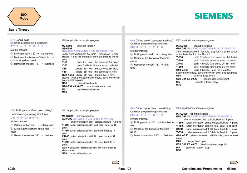
808D Page 101 Operating and Programming — Milling
ISO Mode s
Basic Theory
G76 application example program:
M3 S500 ;spindle rotation G90 G99 G76 X300 Y-250 Z-150 R-100 Q5 P1000 F120
;after orientation bore 1st hole, then move 5 mm, stop for 1 s at the bottom of the hole, back to the R point.
Y-50 ;bore 2nd hole (the same as 1st hole )
Y-80 ;bore 3rd hole (the same as 1st hole)
X10 ;bore 4th hole (the same as 1st hole)
Y10 ;bore 5th hole (the same as1st hole)
G98 Y-750 ;bore 6th hole, then move 5 mm, stop for 1s at the bottom of the hole, back to the start point position plane G80 ;cancel fixed cycle
G28 G91 X0 Y0 Z0 ;back to reference point
M5 ;spindle rotation stop M30
G76 Boring cycle Common programming structures:
G76 X—Y—Z—R—Q—P—F—K
Motion process:
① Drilling motion (-Z) → cutting feed
② Motion at the bottom of the hole → spindle stop directional
③ Retraction motion (+Z) → fast feed
G81 Drilling cycle (fixed point drilling)
Common programming structures:
G81 X—Y—Z—R—F—K
Motion process:
① Drilling motion (-Z) → cutting feed
② Motion at the bottom of the hole → none
③ Retraction motion (+Z) → fast feed
G81 application example program:
M3 S2000 ;spindle rotation G90 G99 G81 X300 Y-250 Z-150 R-10 F120
;after orientation drill 1st hole, back to R point
Y-550 ;after orientation drill 2nd hole, back to R point Y-750 ;after orientation drill 3rd hole, back to R point
X1000 ;after orientation drill 4th hole, back to R point
Y-550 ;after orientation drill 5th hole, back to R point
G98 Y-750;after orientation drill 6th hole, back to start plane G80 ;cancel fixed cycle
G82 application example program:
M3 S2000 ;spindle rotation G90 G99 G82 X300 Y-250 Z-150 R-100 P1000 F120
;after orientation drill 1st hole, stop for 1 s at the bottom of the hole, back to the R point. Y-550 ;drill 2nd hole (the same as 1st hole)
Y-750 ;drill 3rd hole (the same as 1st hole)
X1000 ;drill 4th hole (the same as 1st hole)
Y-550 ;drill 5th hole (the same as 1st hole)
G98 Y-750 ;drill 6th hole, stop for 1 s at the bottom of the hole, back to the start point position plane
G80 ;cancel fixed cycle
G28 G91 X0 Y0 Z0 ;back to reference point
M5 ;spindle rotation stop M30
G82 Drilling cycle (countersink drilling)
Common programming structures:
G82 X—Y—Z—R—P—F—K
Motion process:
① Drilling motion(-Z) → cutting feed
② Motion at the bottom of the hole → pause
③ Retraction motion (+Z) → fast
feed
G83 Drilling cycle (deep hole drilling)
Common programming structures
G83 X—Y—Z—R—Q—F—K
Motion process:
① Drilling motion (-Z) → intermission
feed
② Motion at the bottom of the hole → None
③ Retraction motion (+Z) → fast feed
G83 application example program:
M3 S2000 ;spindle rotation G90 G99 G83 X300 Y-250 Z-150 R-100 Q15 F120
;after orientation drill 1st hole, back to R point
Y-550. ;after orientation drill 2nd hole, back to R point
Y-750. ;after orientation drill 3rd hole, back to R point
X1000. ;after orientation drill 4th hole, back to R point
Y-550. ;after orientation drill 5th hole, back to R point
G98 Y-750. ;after orientation drill 6th hole, back to start plane G80 ;cancel fixed cycle
G28 G91 X0 Y0 Z0 ;back to reference point
M5 ;spindle rotation stop M30

Operating and Programming — Milling Page 102 808D
ISO Mode s
Basic Theory
G84 execution operation graphic: With command G99 without operation in red line With command G98 with operation in red line
G84 Tapping cycle
Common programming structures:
G84 X—Y—Z—R—P—F—K
Motion process:
① Drilling motion (-Z) → cutting feed
② Motion at the bottom of the hole → spindle rotation in negative direction
③ Retraction motion (+Z) → cutting feed
G85 boring cycle
Common programming structures:
G85 X—Y—Z—R—F—K
Motion process:
① Drilling motion (-Z) → cutting feed
② Motion at the bottom of the hole → none
③ Retraction motion (+Z) → cutting feed
G85 execution operation graphic: With command G99 without operation in red line With command G98 with operation in red line Except that the spindle is not rotating at the bottom of the hole, G85 is same as G84
G86 execution operation graphic: With command G99 without operation in red line With command G98 with operation in red line Except for the stop at the bottom of the hole, G86 is same as G81
G86 boring cycle
Common programming structures:
G86 X—Y—Z—R—F—K
Motion process:
① Drilling motion (-Z) → cutting feed
② Motion at the bottom of the hole → spindle stop
③ Retraction motion (+Z) → fast feed
G89 boring cycle
Common programming structures:
G89 X—Y—Z—R—P—F—L
Motion process:
① Drilling motion (-Z) → cutting feed
② Motion at the bottom of the hole → pause
③ Retraction motion (+Z) → cutting
feed
G89 execution operation graphic: With command G99 without operation in red line With command G98 with operation in red line Except that the spindle stops at the bottom of the hole, G89 is same as G85
Origin
spindle CW after pause
R Point
Z Point
spindle CCW after pause
Origin
R Point
Z Point
Origin
R Point
Z Point
Pause
spindle CW after pause
Origin spindle CW after pause
R Point
Z Point
spindle stop after pause

808D Page 103 Operating and Programming — Milling
ISO Mode s
Basic Theory
G87 Boring cycleⅠ / reverse boring cycle
Ⅱ
Common programming structures:
G87 X—Y—Z—R—Q—P—F—L
Motion process:
① Drilling motion (-Z) →cutting feed
② Motion at the bottom of the hole → spindle stops
③ Retraction motion (+Z) → manual
operation or fast feed
G87 execution operation
graphic:
Fixed cycle Ⅱ→
G87 execution operation graphic:
Fixed cycleⅠ
Make the necessary changes to the ISO programs.
Programs in ISO mode in the 808D have their own rules. Suitable changes must be made at the appropriate posi-tions so that you can run the ISO programs!
ISO program
transfer and operation
Step 1
The ISO mode function provided by the 808D can easily operate the exist-
ing ISO program!
A specified ISO program is then stored in the 808D system and can be edited and executed as described above.
Transfer ISO files in USB device to 808D.
Press the “NC” SK on the PPU.
Press the “USB” SK on the PPU.
Press the “Copy” SK on the PPU.
Press the “Paste” SK on the PPU.
Connect the USB device with the stored target programs to the USB interface on the PPU.
Step 2
Use the “Cursor + Select” keys to select the required program which is then highlighted. +
R Point
Z Point
spindle start
spindle start
Cutting feed
Fast feed
Tools move
Manual feed
spindle start
spindle stop
Origin
Z Point
R Point
Z Point
spindle start
spindle stop
Positioning of Spindles
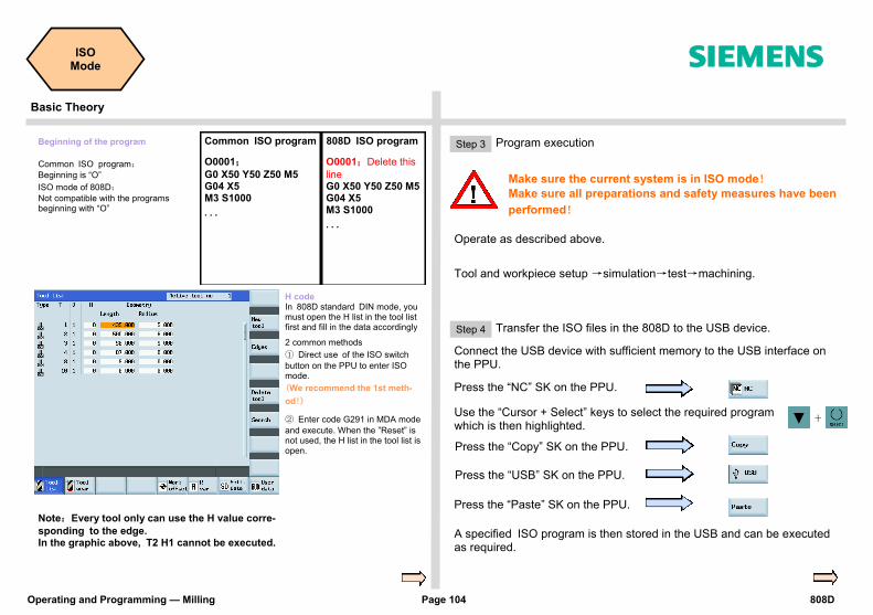
Operating and Programming — Milling Page 104 808D
ISO Mode s
Basic Theory
Beginning of the program
Common ISO program: Beginning is “O”
ISO mode of 808D: Not compatible with the programs beginning with “O”
O0001; G0 X50 Y50 Z50 M5 G04 X5 M3 S1000
...
O0001;Delete this
line G0 X50 Y50 Z50 M5 G04 X5 M3 S1000
...
Common ISO program 808D ISO program
H code In 808D standard DIN mode, you must open the H list in the tool list first and fill in the data accordingly 2 common methods
① Direct use of the ISO switch
button on the PPU to enter ISO mode.
(We recommend the 1st meth-
od!)
② Enter code G291 in MDA mode
and execute. When the ”Reset” is not used, the H list in the tool list is open.
Step 3
A specified ISO program is then stored in the USB and can be executed as required.
Program execution
Press the “USB” SK on the PPU.
Press the “NC” SK on the PPU.
Press the “Copy” SK on the PPU.
Press the “Paste” SK on the PPU.
Connect the USB device with sufficient memory to the USB interface on the PPU.
Make sure the current system is in ISO mode! Make sure all preparations and safety measures have been
performed!
Operate as described above.
Tool and workpiece setup →simulation→test→machining.
Step 4 Transfer the ISO files in the 808D to the USB device.
Use the “Cursor + Select” keys to select the required program which is then highlighted.
Note:Every tool only can use the H value corre-
sponding to the edge. In the graphic above, T2 H1 cannot be executed.
+
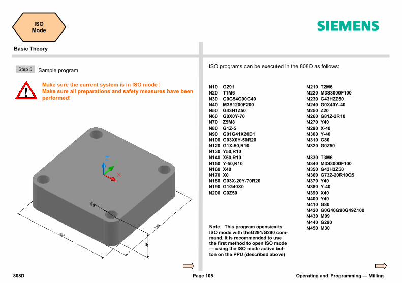
808D Page 105 Operating and Programming — Milling
ISO Mode s
Basic Theory
ISO programs can be executed in the 808D as follows:
N10 G291
N20 T1M6
N30 G0G54G90G40
N40 M3S1200F200
N50 G43H1Z50
N60 G0X0Y-70
N70 Z5M8
N80 G1Z-5
N90 G01G41X20D1
N100 G03X0Y-50R20
N120 G1X-50,R10
N130 Y50,R10
N140 X50,R10
N150 Y-50,R10
N160 X40
N170 X0
N180 G03X-20Y-70R20
N190 G1G40X0
N200 G0Z50
Note:This program opens/exits
ISO mode with theG291/G290 com-mand. It is recommended to use the first method to open ISO mode — using the ISO mode active but-ton on the PPU (described above)
N210 T2M6
N220 M3S3000F100
N230 G43H2Z50
N240 G0X40Y-40
N250 Z20
N260 G81Z-2R10
N270 Y40
N290 X-40
N300 Y-40
N310 G80
N320 G0Z50
N330 T3M6
N340 M3S3000F100
N350 G43H3Z50
N360 G73Z-20R10Q5
N370 Y40
N380 Y-40
N390 X40
N400 Y40
N410 G80
N420 G0G40G90G49Z100
N430 M09
N440 G290
N450 M30
Step 5
Make sure the current system is in ISO mode! Make sure all preparations and safety measures have been performed!
Sample program
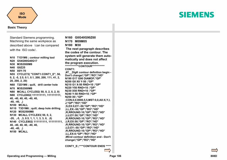
Operating and Programming — Milling Page 106 808D
ISO Mode s
Basic Theory
N10 T1D1M6 ; contour milling tool
N20 G54G90G40G17
N30 M3S2000M8
N40 G0Z25
N50 X0Y-70
N55 CYCLE72( "CONT1:CONT1_E", 50,
0, 2, -5, 2.5, 0.1, 0.1, 200, 200, 111, 41, 2,
20, 200, 2, 20)
N60 T2D1M6 ; quill, drill center hole
N70 M3S2500M8
N80 MCALL CYCLE82( 50, 0, 2, 0, 2, 0)
N90 CYCLE802( 111111111, 111111111,
40, -40, 40, 40, -40, 40,
-40, -40, ,)
N100 MCALL
N110 T3D1M6 ; quill; deep hole drilling
N120 M3S2500M8
N130 MCALL CYCLE83( 50, 0, 2,
-20, ,-5, ,3, 0.5, 1, 1, 1, 3, 3, 0, ,0)
N140 CYCLE802( 111111111, 111111111,
40, -40, 40, 40, -40, 40,
-40, -40, ,)
N150 MCALL
N160 G0G40G90Z60
N170 M09M05
N180 M30
The next paragraph describes the codes of the contour. The system will generate them auto-matically and does not affect the program execution. *************CONTOUR************ CONT1: ;#7__DlgK contour definition begin - Don't change!;*GP*;*RO*;*HD* N190 G17 G90 DIAMOF;*GP* N200 G0 X0 Y-50 ;*GP* N210 G1 X-50 RND=10 ;*GP* N220 Y50 RND=10 ;*GP* N230 X50 RND=10 ;*GP* N240 Y-50 RND=10 ;*GP* N250 X0 ;*GP* ;CON,0,0.0000,5,5,MST:0,0,AX:X,Y,I,J;*GP*;*RO*;*HD* ;S,EX:0,EY:-50;*GP*;*RO*;*HD* ;LL,EX:-50;*GP*;*RO*;*HD* ;R,RROUND:10;*GP*;*RO*;*HD* ;LU,EY:50;*GP*;*RO*;*HD* ;R,RROUND:10;*GP*;*RO*;*HD* ;LR,EX:50;*GP*;*RO*;*HD* ;R,RROUND:10;*GP*;*RO*;*HD* ;LD,EY:-50;*GP*;*RO*;*HD* ;R,RROUND:10;*GP*;*RO*;*HD* ;LL,EX:0;*GP*;*RO*;*HD* ;#End contour definition end - Don't change!;*GP*;*RO*;*HD* CONT1_E:;****CONTOUR ENDS *****
Standard Siemens programming. Machining the same workpiece as
described above (can be compared
with the ISO code).

808D Page 107 Operating and Programming — Milling
Notes
s
Operating and Programming — Milling Page 108
Notes
s

808D Page 109 Operating and Programming — Milling
Appendix s
Unit Content
G Functions
Group 1: Modally valid motion commands
Name Meaning
G00 Rapid traverse
G01 * Linear interpolation
G02 Circular interpolation clockwise
G03 Circular interpolation counter-clockwise
CIP Circular interpolation through intermediate point
CT Circular interpolation; tangential transition
G33 Thread cutting with constant lead
G331 Thread interpolation
G332 Thread interpolation - retraction
Group 2: Non-modally valid motion, dwell
Name Meaning
G04 Dwell time preset
G63 Tapping without synchronization
G74 Reference point approach with synchronization
G75 Fixed point approach
G147 SAR - Approach with a straight line
G148 SAR - Retract with a straight line
G247 SAR - Approach with a quadrant
G248 SAR - Retract with a quadrant
G347 SAR - Approach with a semicircle
G348 SAR - Retract with a semicircle
G Functions
Technical Support Contact
Useful Siemens Websites
End

Operating and Programming — Milling Page 110 808D
Appendix s
Group 3: Programmable frame
Name Meaning
TRANS Translation
ROT Rotation
SCALE Programmable scaling factor
MIRROR Programmable mirroring
ATRANS Additive translation
AROT Additive programmable rotation
ASCALE Additive programmable scaling factor
AMIRROR Additive programmable mirroring
G110 Pole specification relative to the last programmed setpoint position
G111 Pole specification relative to origin of current workpiece coordinate system
G112 Pole specification relative to the last valid POLE
Group 6: Plane selection
Name Meaning
G17 * X/Y plane
G18 Z/X plane
G19 Y/Z plane
Group 7: Tool radius compensation
Name Meaning
G40 * Tool radius compensation OFF
G41 Tool radius compensation left of contour
G42 Tool radius compensation right of contour
Group 8: Settable zero offset
Name Meaning
G500 * Settable work offset OFF
G54 1st settable zero offset
G55 2nd settable zero offset
G56 3rd settable zero offset
G57 4th settable zero offset
G58 5th settable zero offset
G59 6th settable zero offset
Group 9: Frame suppression
Name Meaning
G53 Non-modal skipping of the settable work offset
G153 Non-modal skipping of the settable work offset including base frame
Group 10: Exact stop — continuous – path mode
Name Meaning
G60 * Exact positioning
G64 Continuous — path mode
Group 11: Exact stop, non-modal
Name Meaning
G09 Non-modal exact stop
Group 12: Exact stop window modally effective
Name Meaning
G601 * Exact stop window
G602 Exact stop window, course, with G60, G9
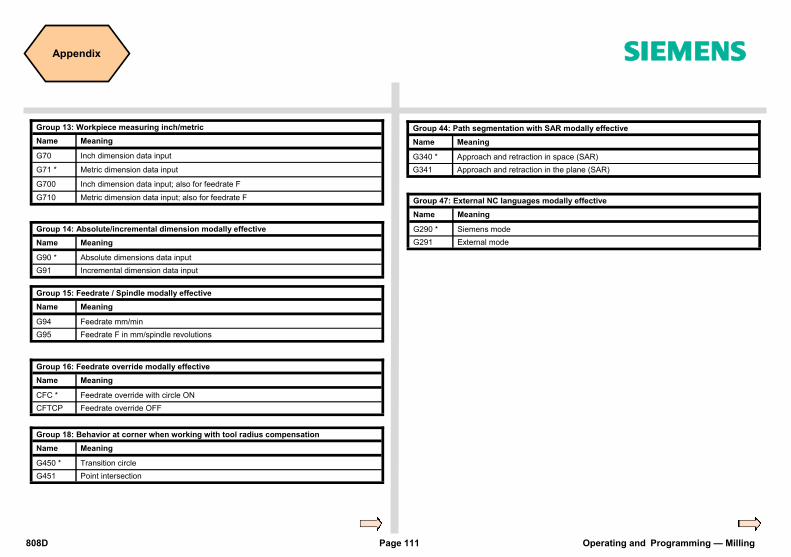
808D Page 111 Operating and Programming — Milling
Appendix s
Group 13: Workpiece measuring inch/metric
Name Meaning
G70 Inch dimension data input
G71 * Metric dimension data input
G700 Inch dimension data input; also for feedrate F
G710 Metric dimension data input; also for feedrate F
Group 14: Absolute/incremental dimension modally effective
Name Meaning
G90 * Absolute dimensions data input
G91 Incremental dimension data input
Group 15: Feedrate / Spindle modally effective
Name Meaning
G94 Feedrate mm/min
G95 Feedrate F in mm/spindle revolutions
Group 16: Feedrate override modally effective
Name Meaning
CFC * Feedrate override with circle ON
CFTCP Feedrate override OFF
Group 47: External NC languages modally effective
Name Meaning
G290 * Siemens mode
G291 External mode
Group 18: Behavior at corner when working with tool radius compensation
Name Meaning
G450 * Transition circle
G451 Point intersection
Group 44: Path segmentation with SAR modally effective
Name Meaning
G340 * Approach and retraction in space (SAR)
G341 Approach and retraction in the plane (SAR)

Operating and Programming — Milling Page 112 808D
Appendix s
Technical Support If you have any questions about this product or this manual, contact the hotline:
Phone +86 1064 719990
Fax +86 1064 719991
E-mail [email protected]
SINUMERIK Internet address Further product information can be found at the following web site:
http://www.siemens.com/sinumerik
Technical Support Contact
Useful Siemens Websites

808D Page 113 Operating and Programming — Milling
Notes
s
Everything ever wanted to know about SINUMERIK 808D: www.automation.siemens.com/mcms/m2/en/automation-systems/cnc-sinumerik/sinumerik-controls/sinumerik-808/Pages/sinumerik-808.aspx Everything about shopfloor manufacturing: www.siemens.com/cnc4you Everything about the SINUMERIK Manufacturing Excellence portfolio of services: www.siemens.com/sinumerik/manufacturing-excellence Information about CNC training: www.siemens.com/sinumerik/training
Siemens AG Industry Sector Motion Control Systems P.O.Box 3180 91050 ERLANGEN GERMANY
Subject to change without prior notice Order No.: Dispostelle 06311 WÜ/35557 WERK.52.2.01 WS 11113.0 Printed in Germany © Siemens AG 2012
The information provided in this brochure contains merely general descriptions or characteristics of performance which in actual case of use do not always apply as described or which may change as a result of further development of the products. An obligation to provide the respective characteristics shall only exist if expressly agreed in the terms of contract. All product designations may be trademarks or product names of Siemens AG or supplier companies whose use by third parties for their own purposes could violate the rights of the owners.