80i-110s - flukeassets.fluke.com/manuals/80i-110sumeng0000.pdf80i-110s instruction manual 3...
TRANSCRIPT

Table of Contents 3
November 1996� 1994, 1996 Fluke Corporation. All rights reserved. All product names are trademarks of their respective companies.Printed in the Netherlands
80i-110sAC/DC CURRENT PROBE
Users Manual
®


Table of Contents 1
Table of Contents
INTRODUCING THE CURRENT PROBE . . . . . . . . . . . . . . . . . . . . . . . . . . . . 3UNPACKING . . . . . . . . . . . . . . . . . . . . . . . . . . . . . . . . . . . . . . . . . . . . . . . . . . 4INSTALLING THE BATTERY . . . . . . . . . . . . . . . . . . . . . . . . . . . . . . . . . . . . . . 5USING THE CURRENT PROBE SAFELY . . . . . . . . . . . . . . . . . . . . . . . . . . . . 6ELECTRICAL SPECIFICATIONS . . . . . . . . . . . . . . . . . . . . . . . . . . . . . . . . . . . 7GENERAL SPECIFICATIONS . . . . . . . . . . . . . . . . . . . . . . . . . . . . . . . . . . . . . 9SAFETY SPECIFICATIONS . . . . . . . . . . . . . . . . . . . . . . . . . . . . . . . . . . . . . . 10BATTERY INFORMATION . . . . . . . . . . . . . . . . . . . . . . . . . . . . . . . . . . . . . . . 10INSTRUMENT COMPATIBILITY . . . . . . . . . . . . . . . . . . . . . . . . . . . . . . . . . . 11USING THE CURRENT PROBE . . . . . . . . . . . . . . . . . . . . . . . . . . . . . . . . . . 12MEASUREMENT CONSIDERATIONS . . . . . . . . . . . . . . . . . . . . . . . . . . . . . 14MAINTENANCE . . . . . . . . . . . . . . . . . . . . . . . . . . . . . . . . . . . . . . . . . . . . . . . 15CLEANING AND STORAGE . . . . . . . . . . . . . . . . . . . . . . . . . . . . . . . . . . . . . 15PERFORMANCE VERIFICATION . . . . . . . . . . . . . . . . . . . . . . . . . . . . . . . . . 16REPLACEMENT PARTS . . . . . . . . . . . . . . . . . . . . . . . . . . . . . . . . . . . . . . . . 20


80i-110s Instruction Manual 3
INTRODUCING THE CURRENT PROBE
The Fluke 80i-110s is a clamp-on AC/DC Current Probe that reproduces currentwaveforms found in modern commercial and industrial power distribution sys-tems. The probe's performance is optimized for accurate reproduction of currentsat line frequency and up to the 50th harmonic waveform. The 80i-110s is alsocompatible with any instrument capable of millivolt measurements. The CurrentProbe (shown in Figure 1) provides the following benefits:
• Accurate AC, DC and AC+DC current measurements for Electrical, Electronicand Automotive applications.
• Shielded for high noise immunity around electronic motor drives and ignitionsystems.
• Wide measurement range from 50 milliamps to 100 amps, useful to 10milliamps.
• Jaw shaped for easy access to cramped spaces.
• Safety-designed 600 volt insuIated BNC - compatible with Fluke ScopeMeter�
test tools, Power Harmonic analyzers, and oscilloscopes.
• Selectable output of 10 millivolts per 1 amp for the 100 A range, and 100millivolts per 1 amp for the 10 A range.
Figure 1. 80i-110s AC/DC Current Probe

4 80i-110s Instruction Manual
UNPACKING
The following items should be included in your Current Probe box:
• AC/DC Current Probe, 80i-110s
• Users Manual (this book)
• Quick Reference Card
• 9 volt Battery, type IEC 6LR61
Check the contents of the shipping box for completeness. If something in the boxhas been damaged or missing, contact your distributor or the nearest FLUKEsales or service office immediately.

80i-110s Instruction Manual 5
INSTALLING THE BATTERY
WARNING
TO AVOID ELECTRICAL SHOCK, UNCLAMP THE CURRENT PROBE FROMANY CONDUCTOR, AND DISCONNECT THE SCOPEMETER TEST TOOL ORANY OTHER MEASUREMENT DEVICE BEFORE INSTALLING OR REPLACINGTHE BATTERY.
At first use, remember to install the battery. Referring to Figure 2, use the followingprocedure to install the battery:
1. Be sure that you have unclamped the Current Probe from any conductor andhave disconnected the ScopeMeter test tool or any other measurement device.
2. Be sure that the Current Probe is in the OFF position.
3. Locate the battery cover on the handle. (see Figure 2.) Loosen the screw witha flat-blade screwdriver.
4. Slide the battery cover away from the Current Probe.
5. Install the battery (IEC 6LR61) as shown in Figure 2. Arrange the battery leadsso that they will not be pinched between the handle bottom and the battery cover.
6. Reinstall the battery cover and secure the screw.
Figure 2. Installing the Battery
6 80i-110s Instruction Manual
USING THE CURRENT PROBE SAFELY
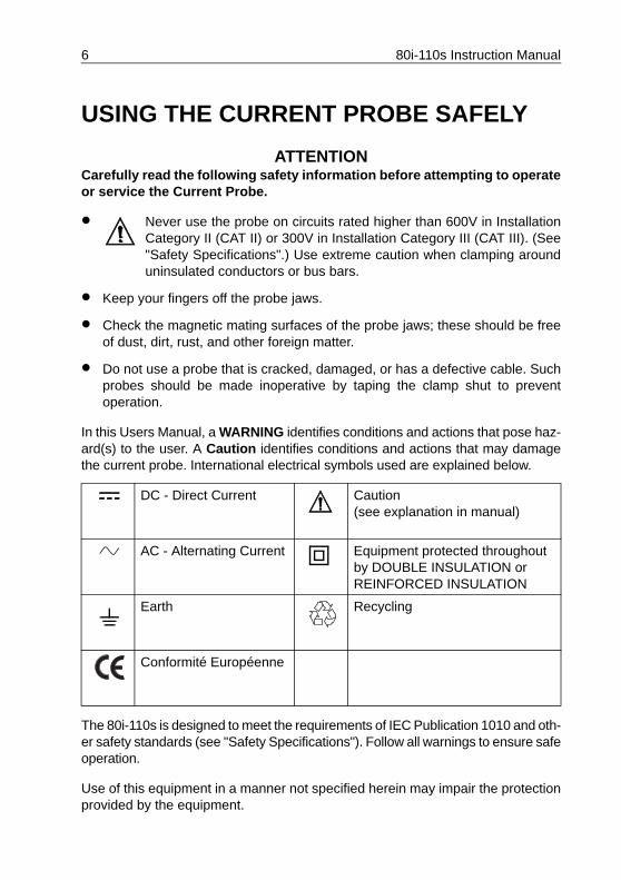
ATTENTION Carefully read the following safety information before attempting to operateor service the Current Probe.
• Never use the probe on circuits rated higher than 600V in InstallationCategory II (CAT II) or 300V in Installation Category III (CAT III). (See"Safety Specifications".) Use extreme caution when clamping arounduninsulated conductors or bus bars.
• Keep your fingers off the probe jaws.
• Check the magnetic mating surfaces of the probe jaws; these should be freeof dust, dirt, rust, and other foreign matter.
• Do not use a probe that is cracked, damaged, or has a defective cable. Suchprobes should be made inoperative by taping the clamp shut to preventoperation.
In this Users Manual, a WARNING identifies conditions and actions that pose haz-ard(s) to the user. A Caution identifies conditions and actions that may damagethe current probe. International electrical symbols used are explained below.
The 80i-110s is designed to meet the requirements of IEC Publication 1010 and oth-er safety standards (see "Safety Specifications"). Follow all warnings to ensure safeoperation.
Use of this equipment in a manner not specified herein may impair the protectionprovided by the equipment.
DC - Direct Current Caution(see explanation in manual)
AC - Alternating Current Equipment protected throughout by DOUBLE INSULATION orREINFORCED INSULATION
Earth Recycling
Conformité Européenne
80i-110s Instruction Manual 7
ELECTRICAL SPECIFICATIONS
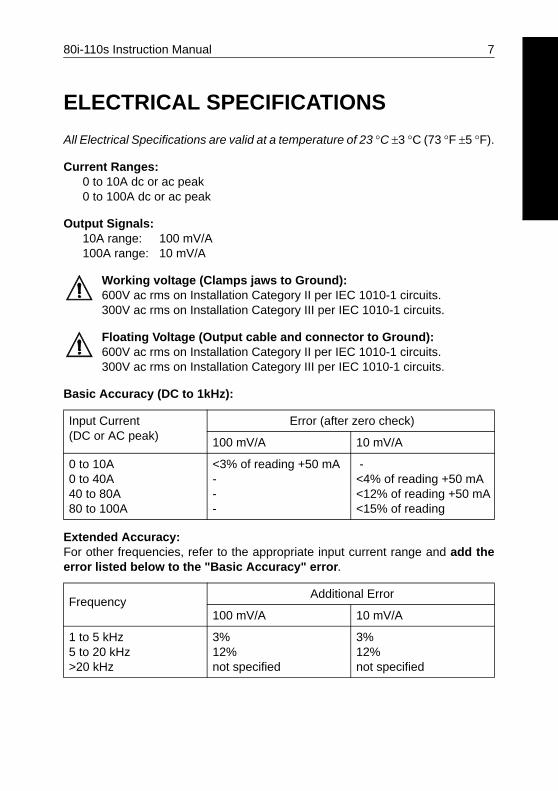
All Electrical Specifications are valid at a temperature of 23 �C �3 �C (73 �F �5 �F).
Current Ranges:0 to 10A dc or ac peak0 to 100A dc or ac peak
Output Signals:10A range: 100 mV/A 100A range: 10 mV/A
Working voltage (Clamps jaws to Ground):600V ac rms on Installation Category II per IEC 1010-1 circuits.300V ac rms on Installation Category III per IEC 1010-1 circuits.
Floating Voltage (Output cable and connector to Ground):600V ac rms on Installation Category II per IEC 1010-1 circuits.300V ac rms on Installation Category III per IEC 1010-1 circuits.
Basic Accuracy (DC to 1kHz):
Extended Accuracy: For other frequencies, refer to the appropriate input current range and add theerror listed below to the "Basic Accuracy" error.
Input Current(DC or AC peak)
Error (after zero check)
100 mV/A 10 mV/A
0 to 10A0 to 40A40 to 80A80 to 100A
<3% of reading +50 mA ---
-<4% of reading +50 mA<12% of reading +50 mA<15% of reading
FrequencyAdditional Error
100 mV/A 10 mV/A
1 to 5 kHz5 to 20 kHz>20 kHz
3%12%not specified
3%12%not specified

8 80i-110s Instruction Manual
Input Load Impedance (of host instrument): >1 M� in parallel with up to 100 pF.
Useful Bandwidth (-3 dB): 0 to 100 kHz
Rise or Fall Time: <4 �sec.
Output noise level:10 mV/A typ. 480 �V pk-pk100 mV/A typ. 3 mV pk-pk
Max. non destructive current:0 to 2 kHz 140A peak2 to 10 kHz 110A peak10 to 20 kHz 70 A peak20 to 50 kHz 30A peak50 to 100 kHz 20A peak
Temperature coefficient:2000 ppm/�C max. for temperature from 0 to 50 �C (32 to 132 �F)
80i-110s Instruction Manual 9
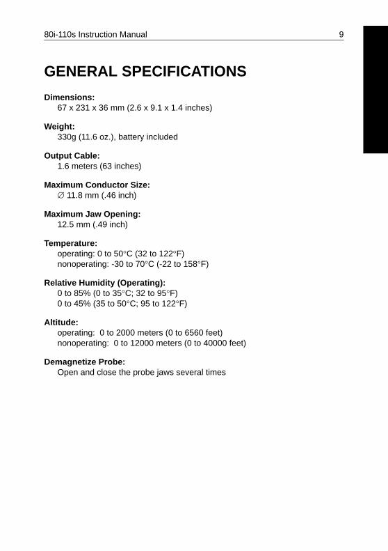
GENERAL SPECIFICATIONS
Dimensions: 67 x 231 x 36 mm (2.6 x 9.1 x 1.4 inches)
Weight: 330g (11.6 oz.), battery included
Output Cable: 1.6 meters (63 inches)
Maximum Conductor Size: � 11.8 mm (.46 inch)
Maximum Jaw Opening: 12.5 mm (.49 inch)
Temperature:operating: 0 to 50�C (32 to 122�F)nonoperating: -30 to 70�C (-22 to 158�F)
Relative Humidity (Operating):0 to 85% (0 to 35�C; 32 to 95�F)0 to 45% (35 to 50�C; 95 to 122�F)
Altitude:operating: 0 to 2000 meters (0 to 6560 feet)nonoperating: 0 to 12000 meters (0 to 40000 feet)
Demagnetize Probe:Open and close the probe jaws several times
10 80i-110s Instruction Manual
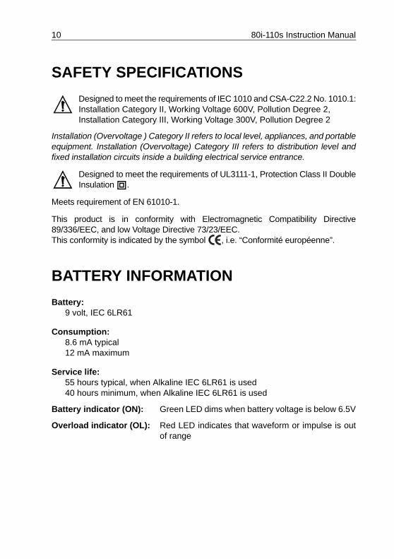
SAFETY SPECIFICATIONS
Designed to meet the requirements of IEC 1010 and CSA-C22.2 No. 1010.1:Installation Category II, Working Voltage 600V, Pollution Degree 2, Installation Category III, Working Voltage 300V, Pollution Degree 2
Installation (Overvoltage ) Category II refers to local level, appliances, and portableequipment. Installation (Overvoltage) Category III refers to distribution level andfixed installation circuits inside a building electrical service entrance.
Designed to meet the requirements of UL3111-1, Protection Class II DoubleInsulation .
Meets requirement of EN 61010-1.
This product is in conformity with Electromagnetic Compatibility Directive89/336/EEC, and low Voltage Directive 73/23/EEC.This conformity is indicated by the symbol , i.e. “Conformité européenne”.
BATTERY INFORMATION
Battery: 9 volt, IEC 6LR61
Consumption:8.6 mA typical12 mA maximum
Service life:55 hours typical, when Alkaline IEC 6LR61 is used40 hours minimum, when Alkaline IEC 6LR61 is used
Battery indicator (ON): Green LED dims when battery voltage is below 6.5V
Overload indicator (OL): Red LED indicates that waveform or impulse is outof range

80i-110s Instruction Manual 11
INSTRUMENT COMPATIBILITY
The 80i-110s is compatible with any Fluke ScopeMeter test tool, Power HarmonicsAnalyzer, Oscilloscope, Multimeter, or other voltage measurement device that hasthe following features:
• BNC input connector. A BNC-to-banana adapter (order PM9081/001 fromFluke) can also be used with standard inputs on a digital multimeter (DMM).
• Input accuracy of 2% or better to take full advantage of the accuracy of the probe.
• Input impedance of greater than or equal to 1 M� in parallel with a maximumof 100 pF.
• A passband of more than four times the frequency of the waveform to bemeasured.

12 80i-110s Instruction Manual
USING THE CURRENT PROBE
To use the Current Probe, follow these instructions:
1. Connect the 80i-110s Current Probe to the desired input on the measuringinstrument. When the ScopeMeter test tool or an oscilloscope is used, it musthave DC coupled input. When you are using a digital multimeter, use the BNC-to-banana adapter (PM9081/001) to connect the probe to the input.
2. On the Current Probe, select the least sensitive range (10 mV/A). Ensure thatthe green ON-indicator lights. See Figure 4 for selector switch and green ON-indicator locations.
3. On the Current Probe, rotate the ZERO thumbwheel to adjust the probereading to zero. See Figure 4 for the ZERO rotary knob location.
4. Select the appropriate probe sensitivity on your ScopeMeter test tool oroscilloscope.
5. Clamp the Current Probe around the conductor; be sure that the arrow markedon the jaw of the Current Probe points toward the correct orientation. (seeFigure 3.)
Figure 3. Orientation of the Current Probe
80i-110s Instruction Manual 13
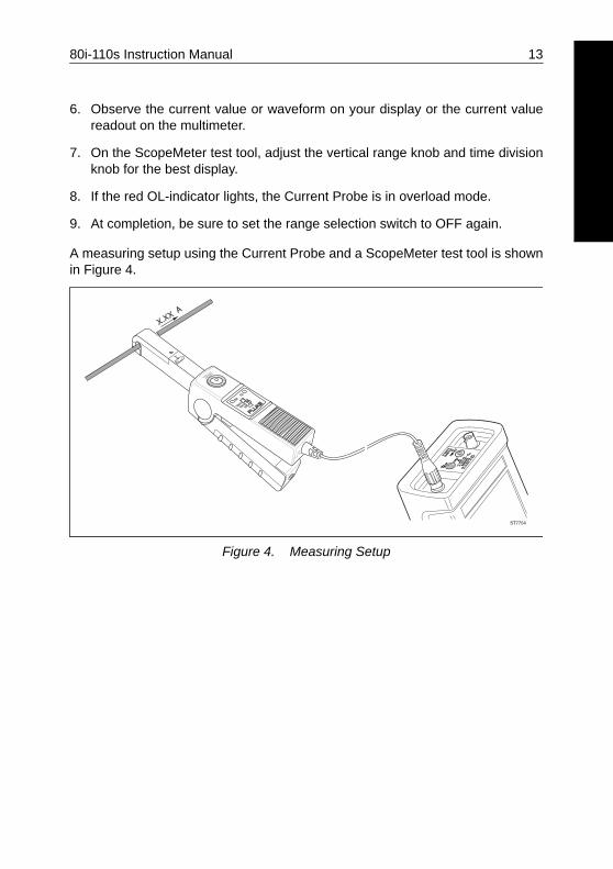
6. Observe the current value or waveform on your display or the current valuereadout on the multimeter.
7. On the ScopeMeter test tool, adjust the vertical range knob and time divisionknob for the best display.
8. If the red OL-indicator lights, the Current Probe is in overload mode.
9. At completion, be sure to set the range selection switch to OFF again.
A measuring setup using the Current Probe and a ScopeMeter test tool is shownin Figure 4.
Figure 4. Measuring Setup

14 80i-110s Instruction Manual
MEASUREMENT CONSIDERATIONS
Observe the following guidelines for positioning the Current Probe Jaws:
• Center the conductor inside the probe jaws.
• Make sure the probe is perpendicular to the conductor.
• Make sure that the arrow marked on the jaw of the Current Probepoints toward the correct direction.
Observe the following guidelines when making measurements:
• If possible, avoid measurements close to other current-carrying conductors.
• On the Current Probe, the 100 mV/A range offers the best accuracy.

80i-110s Instruction Manual 15
MAINTENANCE
Before each use, assure continued safety by inspecting the probe. Look forcracks or missing portions of the probe housing and output cable insulating coverand for loose or weakened components. Pay particular attention to the insulationsurrounding the probe jaws. If a probe fails this inspection, tape it shut to preventunintended operation. To check probe performance, complete the "PerformanceVerification" procedure.
WARNING
THESE SERVICING INSTRUCTIONS ARE FOR USE BY QUALIFIEDPERSONNEL ONLY. TO AVOID ELECTRIC SHOCK, DO NOT PERFORM ANYSERVICING PROCEDURES UNLESS YOU ARE QUALIFIED TO DO SO.READ THE INFORMATION TITLED "USING THE CURRENT PROBE SAFELY"AT THE BEGINNING OF THIS USERS MANUAL BEFORE PROCEEDING.
Repairs or servicing not covered in this Users Manual should be performed onlyat a Fluke Service Center. A probe under warranty will be promptly repaired orreplaced (at Fluke's discretion) and returned at no charge.
CLEANING AND STORAGE
Periodically wipe the case with a damp cloth and detergent; do not use abrasivesor solvents. Open the jaws and wipe the magnetic pole pieces with a lightly oiledcloth. Do not allow rust or corrosion to form on the magnetic core ends. If theprobe is not used for periods of longer than 60 days, the battery should beremoved and stored separately.

16 80i-110s Instruction Manual
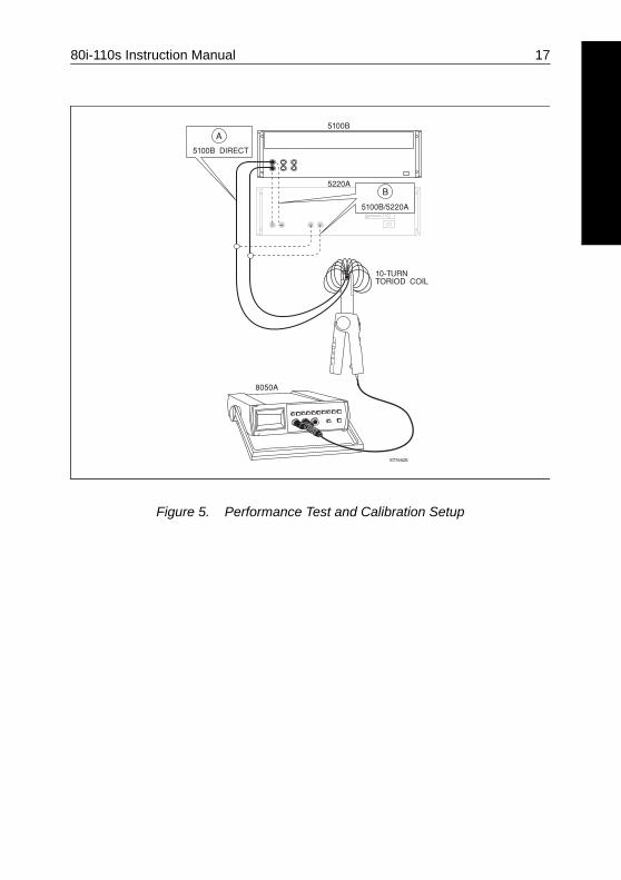
PERFORMANCE VERIFICATION
Verify probe accuracy with the test setups shown in Figure 5. Required testequipment is defined in Table 1. Toroid coil construction is illustrated in Figure 6.
Do the following to verify the probe accuracy:
1. Set up Connection A.
2. Make the checks called for in Table 2.
3. Disconnect Connection A at the 5100B.
4. Set up Connection B
5. Make the checks called for in Table 3.
Table 1. Required Test Equipment
REQUIRED RECOMMENDED MODEL
AC/DC CalibratorTransconductance AmplifierDigital Multimeter (DMM)Small insulated screwdriver Banana-to-BNC Adapter10-Turn Toroid Coil
Fluke Model 5100B Fluke Model 5220AFluke Model 8050ASpectrolFluke Model PM9081/001(see Figure 6.)
80i-110s Instruction Manual 17
Figure 5. Performance Test and Calibration Setup

18 80i-110s Instruction Manual
Figure 6. Toroid Coil Construction
Table 2. Performance Test Points (5100B Direct)
Current range 0 to 10A
DC Measurement:
5100BSETTINGS
DC AMPSMEASURED
LOW LIMITOUTPUT
HIGH LIMITOUTPUT
0.1A0.5A0.9A
1A5A9A
92 mV480 mV868 mV
108 mV520 mV932 mV
80i-110s Instruction Manual 19
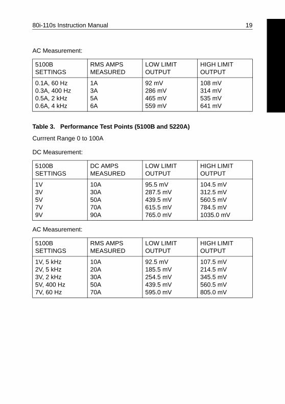
AC Measurement:
Table 3. Performance Test Points (5100B and 5220A)
Currrent Range 0 to 100A
DC Measurement:
AC Measurement:
5100BSETTINGS
RMS AMPSMEASURED
LOW LIMITOUTPUT
HIGH LIMIT OUTPUT
0.1A, 60 Hz0.3A, 400 Hz0.5A, 2 kHz0.6A, 4 kHz
1A3A5A6A
92 mV286 mV465 mV559 mV
108 mV314 mV535 mV641 mV
5100BSETTINGS
DC AMPSMEASURED
LOW LIMITOUTPUT
HIGH LIMITOUTPUT
1V3V5V7V9V
10A30A50A70A90A
95.5 mV287.5 mV439.5 mV615.5 mV765.0 mV
104.5 mV312.5 mV560.5 mV784.5 mV1035.0 mV
5100BSETTINGS
RMS AMPSMEASURED
LOW LIMITOUTPUT
HIGH LIMITOUTPUT
1V, 5 kHz2V, 5 kHz3V, 2 kHz5V, 400 Hz7V, 60 Hz
10A20A30A50A70A
92.5 mV185.5 mV254.5 mV439.5 mV595.0 mV
107.5 mV214.5 mV345.5 mV560.5 mV805.0 mV
20 80i-110s Instruction Manual
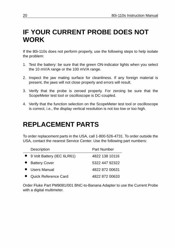
IF YOUR CURRENT PROBE DOES NOT WORK
If the 80i-110s does not perform properly, use the following steps to help isolatethe problem:
1. Test the battery: be sure that the green ON-indicator lights when you selectthe 10 mV/A range or the 100 mV/A range.
2. Inspect the jaw mating surface for cleanliness. If any foreign material ispresent, the jaws will not close properly and errors will result.
3. Verify that the probe is zeroed properly. For zeroing be sure that theScopeMeter test tool or oscilloscope is DC-coupled.
4. Verify that the function selection on the ScopeMeter test tool or oscilloscopeis correct, i.e., the display vertical resolution is not too low or too high.
REPLACEMENT PARTS
To order replacement parts in the USA, call 1-800-526-4731. To order outside theUSA, contact the nearest Service Center. Use the following part numbers:
Order Fluke Part PM9081/001 BNC-to-Banana Adapter to use the Current Probewith a digital multimeter.
Description Part Number
• 9 Volt Battery (IEC 6LR61) 4822 138 10116
• Battery Cover 5322 447 92322
• Users Manual 4822 872 00631
• Quick Reference Card 4822 872 00633