851343 h&c model tlc catalog - edition 3€¦ · stainless steel chimney lengths 3 stainless...
TRANSCRIPT
Edition 3

Order information:To order Hart & Cooley products,please contact any authorizedHart & Cooley distributor orcall 800.433.6341.
When you purchase Hart & Cooley products, youalso receive the full support of Hart & Cooleytechnical and customer service.
Technical and customer service:800.433.6341 toll-free616.656.8200 phone800.223.8461 toll-free fax616.656.6399 fax
Internet address:http: //www.hartandcooley.com
Install confidence with these quality productsfrom Hart & Cooley:• Grilles, Registers & Diffusers• Type B Gas Vent Systems• Special Gas Vent• Model TLC All-Fuel Chimney• Duct System Components• Flexible Duct Systems

Tab
le of Con
tents
1
Table of Contents
INTRODUCTION . . . . . . . . . . . . . . . . . . . . . . . . . . . .2
STAINLESS STEEL CHIMNEY LENGTHS
CHIMNEY SECTIONS . . . . . . . . . . . . . . . . . . . . . .3
STAINLESS STEEL LOCKING BANDS . . . . . . . . .3
STAINLESS STEEL ELBOWS AND TEES
CHIMNEY OFFSET CHARTS . . . . . . . . . . . . . . . . .4
INSULATED 15°, 30° AND 45° ELBOW KITS . . . .6
INSULATED TEE WITH TEE CAP . . . . . . . . . . . . .7
INSULATED TEE CAP . . . . . . . . . . . . . . . . . . . . . .7
SUPPORTS
ADJUSTABLE WALL SUPPORT . . . . . . . . . . . . . .8
ADJUSTABLE INTERMEDIATE WALL SUPPORT .8
CEILING SUPPORTS . . . . . . . . . . . . . . . . . . . . . . .9
CATHEDRAL CEILING SUPPORT BOX . . . . . . . .9
ADJUSTABLE ROOF SUPPORTS . . . . . . . . . . . .10
SHIELDS
ATTIC INSULATION SHIELD . . . . . . . . . . . . . . . .11
FIRESTOP RADIATION SHIELD . . . . . . . . . . . . .11
FIRESTOP/JOIST SHIELD . . . . . . . . . . . . . . . . . .11
RAFTER RADIATION SHIELD . . . . . . . . . . . . . . .12
BLACK WALL THIMBLE . . . . . . . . . . . . . . . . . . . .12
FLASHINGS AND STORM COLLARS
ROOF FLASHING SELECTION CHART . . . . . . .13
ADJUSTABLE FLASHING ASSEMBLY . . . . . . . .13
TALL CONE FLASHING . . . . . . . . . . . . . . . . . . . .13
RUBBER BOOT FLASHING KIT . . . . . . . . . . . . .14
STORM COLLAR . . . . . . . . . . . . . . . . . . . . . . . . .14
SILICONE SEALANT FOR STORM COLLAR . . .14
RAIN CAPS
DELUXE RAIN CAPS . . . . . . . . . . . . . . . . . . . . . .15
SPARK ARRESTERS . . . . . . . . . . . . . . . . . . . . . .15
PARTS AND ACCESSORIES
WALL BAND . . . . . . . . . . . . . . . . . . . . . . . . . . . . .16
ADJUSTABLE CEILING PLATE . . . . . . . . . . . . . .16
STOVEPIPE ADAPTER . . . . . . . . . . . . . . . . . . . .17
SOFFIT PLATE . . . . . . . . . . . . . . . . . . . . . . . . . . .17
MATTE BLACK TRIM COLLAR . . . . . . . . . . . . . .17
ADJUSTABLE UNIVERSAL ROOF GUY KIT . . . .18
SHIELDING INSULATION WRAP . . . . . . . . . . . .18
ANCHOR PLATE . . . . . . . . . . . . . . . . . . . . . . . . .18
TYPICAL INSTALLATIONS
DECORATOR CEILING SUPPORT INSTALLATIONS .19
WALL SUPPORT INSTALLATION . . . . . . . . . . . .19
CATHEDRAL SUPPORT INSTALLATION . . . . . .19
LIMITED LIFETIME WARRANTY . . . . . . . . . . . . . .20
MODEL TLC ALL-FUEL CHIMNEY

Intr
odu
ctio
n
2
Introduction
Model TLC All-Fuel Chimney offers current technology
in factory-built chimney design by providing superior
performance, durability and safety.
Certification & Applications
Model TLC is safety-tested and
listed to applicable UL safety
standards for chimneys serving
solid-fuel and liquid-fuel appliances.
This includes UL 103.
This chimney system is designed for use on
appliances that use solid, liquid or gas fuels under
natural draft conditions.
Allowable flue gas temperatures are:
Type HT Non-HT
5" to 8" 10" to 14"
Maximum Continuous 1000°F 1000°F
Brief Forced Firing (1 hr.) 1400°F 1400°F
Creosote Burn-Out (10 min.) 2100°F 1700°F
Lifetime Warranty
See the written lifetime warranty for all chimney
components on page 20.
Enhanced Features
Model TLC is extremely corrosion-resistant. Both the
inner liner and outer casings are constructed of 304
stainless steel. Embossed couplers do not allow
moisture to penetrate the chimney’s outer wall.
Sections simply twist-lock together and are secured with
Locking Bands. The Model TLC product line features
deluxe chimney support components that will enhance
any installation. Black trims are used to embellish the
chimney support component parts that may be installed
inside the home.
Supports
All Model TLC supports are designed to carry four
times the UL-listed weight of the listed height.
Construction
Sizes: 5" to 14"
Inner Liner (Flue): Type 304 Series Stainless Steel
0.016" thickness
Outer Casing: Type 304 Stainless Steel
0.015" thickness
Insulation: The 1" space between the inner/outer
walls is packed with mineral wool
fiber insulation to provide superior
insulating qualities in a slim-line
design.
AirspaceClearance toCombustibles: 2"
Height Requirements
The chimney must extend at least three feet above
the highest point where it passes through the roof
surface and at
least two feet
higher than any
part of the
building within a
horizontal
distance of ten
feet.
Embossed Coupler
Prevents moisture
penetration.
304 Stainless
Steel Inner Liner
High grade material
heats up quickly to
enhance draft.
304 Stainless Steel
Outer Casing
Premium material
prevents corrosion.
Premium Fiber
Insulation
100% mineral wool
(no chlorides).
Twist-Lock
Connection
Easy assembly.Mineral Wool
Insulation
Augured in for better
insulating value to
keep outside
temperatures low for
safety and inside
temperatures high for
performance.
MODEL TLC ALL-FUEL CHIMNEY

Stain
less Steel C
him
ney L
ength
s
3
Stainless Steel Chimney Lengths
Chimney Lengths
• Slim, advanced design allows for installation between 16" centers
and still provides 2" clearance from combustible material.
• Secure twist-lock design couples chimney sections together with
just a 1/8 turn. Locking bands secure joints.
• Includes locking band.
• Sections overlap by 11/8".
• Chimneys are sized according to the inner diameter and are
available in 5" through 14".
• The outside diameter is 2" larger than the inside diameter.
Stainless Steel Locking Bands
• Locking bands are used at all joints
for safety and stability.
• Locking band flanges engage the curl
in each end of the adjoining sections,
holding them securely together.
Height
A
ID
B
OD
C
Height
A
ID
B
OD
C
10TLC36 36" 10" 12"
5TLC36 36" 5" 7" 10TLC24 24" 10" 12"
5TLC24 24" 5" 7" 10TLC18 18" 10" 12"
5TLC18 18" 5" 7" 10TLC12 12" 10" 12"
5TLC12 12" 5" 7" 10TLC9 9" 10" 12"
5TLC6 6" 5" 7" 10TLC6 6" 10" 12"
6TLC48 48" 6" 8" 12TLC36 36" 12" 14"
6TLC36 36" 6" 8" 12TLC24 24" 12" 14"
6TLC24 24" 6" 8" 12TLC18 18" 12" 14"
6TLC18 18" 6" 8" 12TLC12 12" 12" 14"
6TLC12 12" 6" 8" 12TLC9 9" 12" 14"
6TLC6 6" 6" 8" 12TLC6 6" 12" 14"
7TLC48 48" 7" 9" 14TLC36 36" 14" 16"
7TLC36 36" 7" 9" 14TLC24 24" 14" 16"
7TLC24 24" 7" 9" 14TLC18 18" 14" 16"
7TLC18 18" 7" 9" 14TLC12 12" 14" 16"
7TLC12 12" 7" 9" 14TLC9 9" 14" 16"
7TLC6 6" 7" 9" 14TLC6 6" 14" 16"
8TLC48 48" 8" 10"
8TLC36 36" 8" 10"
8TLC24 24" 8" 10"
8TLC18 18" 8" 10"
8TLC12 12" 8" 10"
8TLC6 6" 8" 10"
14"
8"
7"
Size
DimensionsModel
Number
Model
Number
Dimensions
Size
5"
6"
10"
12"
Dimension
A
5TLCLB 5" 7"
6TLCLB 6" 8"
7TLCLB 7" 9"
8TLCLB 8" 10"
10TLCLB 10" 12"
12TLCLB 12" 14"
14TLCLB 14" 16"
Model
Number Size3/8"
A

Sta
inle
ss S
teel
Elb
ows
and T
ees
4
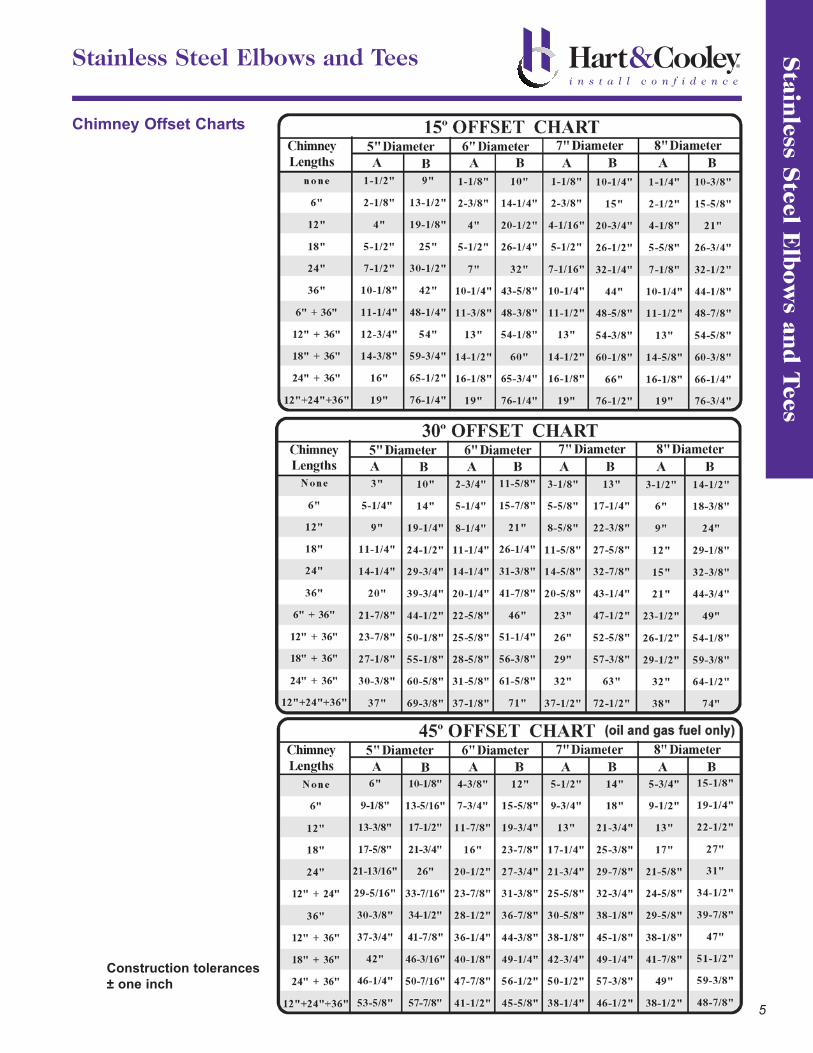
Stainless Steel Elbows and Tees
Chimney Offset Charts
It may be necessary to offset the chimney in order
to clear a joist or an obstacle. The three (3) charts
on the following page will assist you in selecting the
proper combination of elbow angle and chimney
length(s) that will provide the necessary degree of
offset within an available height.
1. Select the column with the proper chimney
diameter of your system.
2. Determine the distance of the offset required by
dropping a plumb line for an accurate
measurement. The offset is measured at the
chimney centerline, as per the "A" Offset
measurement in the diagram below.
3. On the chart, find the predetermined distance
(under the "A" column) required for the 15°
elbow. For greater offset, use the 30° or 45°
offset charts.
NOTE: The 45° elbows may be used
ONLY with oil or gas appliances.
4. After finding the offset, look at the “B” (height)
measurement in the chart to find the specified
height. The appropriate "chimney lengths"
required in between elbows is found in the left-
hand side column of each chart.
NOTE:
• Model TLC chimneys are limited to offsets not
exceeding 30°. Combining offsets for greater
angle is not permitted. The 45° elbows may
be used ONLY with oil or gas appliances.
• One pair of (two) elbows may be used for
interior installation only.
• Never install an elbow in a joist area. Chimney
sections must pass vertically through framed
joist areas.
• Locking Bands must be used at all chimney
joints.
• Each elbow resupport will support 15 feet of
chimney.
• The maximum length of chimney allowed
between elbows is 6 feet.A
B
Stain
less Steel E
lbow
s and T
ees
5
Stainless Steel Elbows and Tees
Chimney Offset Charts
Construction tolerances
± one inch

Sta
inle
ss S
teel
Elb
ows
and T
ees
6
Stainless Steel Elbows and Tees
Insulated 15°, 30° and 45° Elbow Kits
• The insulated elbow is used when offset is required.
• Locking bands must be used on all elbows.
• A maximum of 6 feet is allowable between offsets.
• Elbow is fully insulated and can be used with the same 2-inch clearance as chimney lengths.
• Elbow support must be used with all offset installations and will support 15 feet of chimney.
• Elbows do not have twist-locking ridges, so they can be rotated to attain optimum positioning offset and allow
chimney to return to correct vertical alignment prior to installing locking bands.
• May not be used outdoors.
• 10", 12" and 14" sizes available in 15° and 30° elbow kits only.
• 45° elbows may be used only with oil or gas appliances.
• Elbow kits include: 2 elbows (Exception: 12" and 14" sizes include four 15° elbows assembled into two 30° elbows)
4 locking bands (Exception: 10", 12" and 14" sizes include two locking bands)
1 elbow support
All hardware
A B* C
5" 5TLCEK15 33/8 27/16 115/16
6" 6TLCEK15 33/8 21/2 2
7" 7TLCEK15 33/8 29/16 21/16
8" 8TLCEK15 33/8 25/8 21/8
10" 10TLCEK15 21/2 51/2 N/A
12" 12TLCEK15 21/4 53/4 N/A
14" 14TLCEK15 2 6 N/A
A B C
5" 5TLCEK30 23/4 29/16 29/16
6" 6TLCEK30 31/4 31/16 29/16
7" 7TLCEK30 33/4 37/16 215/16
8" 8TLCEK30 41/4 37/8 33/8
10" 10TLCEK30 5 37/8 31/2
12" 12TLCEK30 4 41/4 4
14" 14TLCEK30 41/4 41/4 41/4
A B C
5" 5TLCEK45 115/16 23/4 23/8
6" 6TLCEK45 21/8 31/8 29/16
7" 7TLCEK45 23/8 33/8 3
8" 8TLCEK45 29/16 33/4 35/16
Size
Model
Number
Dimensions (inches)
45° elbows may be used only
with oil or gas appliances.
*10" to 14" 15° elbows B dimension is total height.
Dimensions (inches)
Size
Model
Number
15°
45°
Size
Model
Number
Dimensions (inches)
30°

Stain
less Steel E
lbow
s and T
ees
7
Stainless Steel Elbows and Tees
Insulated Tee with Tee Cap
• The insulated chimney tee may be used for
through-the-wall installation, using a wall support.
• A chimney length is required to pass safely
through a wall.
• Includes the following:
- Two locking bands
- 5" to 8" sizes have an uninsulated (single-wall)
twist-lock tee cap for non-wall
support applications only.
- 10" to 14" sizes have an
insulated press fit tee cap.
OD
A
ID
B
Height
C D E
5TLCT 5" 7 5 101/2 5 5
6TLCT 6" 8 6 111/2 55/8 53/4
7TLCT 7" 9 7 121/4 61/4 63/16
8TLCT 8" 10 8 133/8 65/8 61/2
10TLCT 10" 12 10 163/4 83/8 83/8
12TLCT 12" 14 12 183/4 93/8 93/8
14TLCT 14" 16 14 203/4 103/8 103/8
Model
Number Size
Dimensions (inches)
Insulated Tee Cap
• Permits typical 2" airspace clearance to combustibles.
• 5" to 8" sizes are twist-lock and for non-wall support
applications only.
• 10" to 14" sizes are press-fit design.
OD
A
ID
B C
5TLCITP 5" 7 5 27/8
6TLCITP 6" 8 6 27/8
7TLCITP 7" 9 7 27/8
8TLCITP 8" 10 8 27/8
10TLCITP 10" 12 10 N/A
12TLCITP 12" 14 12 N/A
14TLCITP 14" 16 14 N/A
Model
Number Size
Dimensions (inches)

Adjustable Wall Support
• Used to support the chimney on a
through-the-wall installation.
• 5" to 8" sizes include top plate, side
brackets, hardware, non-twist-lock
insulated tee cap, and a long L-bracket
to hold tee cap in place.
• 10" to 14" sizes do not include the cap.
Use tee cap packaged with tee.
• 2" to 6" clearance away from
wall.
• 5" to 8" sizes support between
30 feet and 74 feet of chimney,
based on size and orientation.
See instructions for specific
heights.
• 10" to 14" sizes support up to
40 feet of chimney.
• 12" to 14" sizes are
nonadjustable supports.
Adjustable Intermediate Wall Support
• Used as supplementary
support when chimney
system height exceeds
maximum height allowed by
wall support.
• Supports an additional 38
feet of chimney.
• Includes top plate, support
band, side brackets, and
hardware.
• 2" to 6" clearance away from wall.
Su
ppor
ts
8
Supports
Dimension (inches)
A
6TLCIWS 6" 11
7TLCIWS 7" 12
8TLCIWS 8" 13
Model
Number Size
A B C Adjustability
5TLCAWS 5" 12 105/8 187/8 4
6TLCAWS 6" 12 105/8 187/8 4
7TLCAWS 7" 13 115/8 201/2 4
8TLCAWS 8" 14 125/8 217/8 4
10TLCAWS 10" 16 145/8 251/4 4
12TLCAWS 12" 19 161/2 23
14TLCAWS 14" 21 181/2 27
Model
Number Size
Dimension (inches)
nonadjustable
L-Bracket
(5" to 8" sizes)
Non-Twist-Lock
Insulated Tee Cap
(5" to 8" sizes)

Cathedral Ceiling Support Box
• Used in pitched ceiling support
installations.
• Supports a total of 38 feet of
chimney with up to 15 feet below
support. Includes support clamp,
allowing chimney pipe to pass
below support.
• Matte black finish with ceiling trim to
cover rough opening.
• Also acts as a firestop with use of
trim plate.
• 12/12 maximum pitch.
Su
pports
9
Supports
A B
5TLCCSS 5" 71/8 11
6TLCCSS 6" 81/8 12
7TLCCSS 7" 91/8 13
8TLCCSS 8" 101/8 14
Model
Number
Dimensions (inches)
Size
Ceiling Supports
• For use in ceiling support installations.
• Supports a total of 50 feet of chimney above.
• Chimney pipe cannot pass below support.
• Matte black finish with ceiling ring to cover rough
opening.
• Also acts as a firestop.
• Must always use stovepipe adapter. See page 17.
A B C
5TLCCSR 5" 167/8 113/8 63/4
6TLCCSR 6" 177/8 123/8 73/4
7TLCCSR 7" 187/8 133/8 83/4
8TLCCSR 8" 195/8 143/8 93/4
10TLCCS 10" 181/2 161/4 101/4
Model
Number Size
Dimensions (inches)
5" to 8" sizes
(painted black)
10" size
(unpainted)

Su
ppor
ts
10
Supports
Adjustable Roof Support
• The roof support may be used on a
floor, ceiling or roof, and adjusts to
any roof pitch.
• It may be used above an offset to
support the offset or as a
supplementary support when the
chimney height exceeds that of the
primary support.
• Supports a total of 50 feet of
chimney with up to 20 feet below
support.
• Does not act as a firestop.
A B
5TLCRS 5" 7 16
6TLCRS 6" 8 17
7TLCRS 7" 9 18
8TLCRS 8" 10 19
Model
Number Size
Dimensions (inches)
Adjustable Roof Support
• Contains one 18-inch
length of pipe with roof
brackets preinstalled.
Includes hardware.
• Fits all roof pitches.
Mounts easily on top of
roof.
• Supports a total of
30 feet with up to
20 feet below the
support.
• Does not act as a
firestop.
A B
10TLCRS 10" 10 12
12TLCRS 12" 12 14
14TLCRS 14" 14 16
Model
Number Size
Dimensions (inches)

Sh
ields
11
Shields
Attic Insulation Shield
• The attic insulation
shield must be
installed where the
chimney enters the
attic space in any
installation.
• Designed to keep
insulation away from
the chimney and to
maintain the
mandatory 2-inch clearance to combustibles.
• Must be used when the chimney penetrates an unoccupied attic.
• Also acts as a firestop.
• Not to be used for enclosed chimneys passing through attic.
Instead, use firestop radiation shield and rafter radiation shield.
A B C
5TLCIS 5" 11 71/8 13
6TLCIS 6" 12 81/8 14
7TLCIS 7" 13 91/8 15
8TLCIS 8" 14 101/8 16
10TLCIS 10" 16 121/8 18
12TLCIS 12" 18 141/8 20
14TLCIS 14" 20 161/8 22
Model
Number Size
Dimensions (inches)
Firestop Radiation Shield
• Required where
an enclosed
chimney passes
from a lower
living space into
an upper living
space.
• Maintains the
mandatory 2-inch
clearance to
combustibles.
A B
5TLCFRS 5" 13 9
6TLCFRS 6" 14 10
7TLCFRS 7" 15 11
8TLCFRS 8" 16 12
Model
Number Size
Dimensions (inches)
Firestop/Joist Shield
• Used in floor/ceiling penetrations, other than those that
include a ceiling support.
• Not required when passing through roof.
A B C D
10TLCFRS 10" 121/8 14 18 16
12TLCFRS 12" 141/8 16 20 18
14TLCFRS 14" 161/8 18 22 20
Model
Number Size
Dimensions (inches)
Can be installed in either orientation

Sh
ield
s
12
Shields
Rafter Radiation Shield
• The rafter radiation
shield must be
installed
immediately below
the roof flashing,
inside any
enclosure.
Dimension (inches)
A
5TLCRRS 5" 9
6TLCRRS 6" 10
7TLCRRS 7" 11
8TLCRRS 8" 12
Model
Number Size
Black Wall Thimble
• Used in a wall support
installation.
• Radiation shield is included
with spacers, which maintain
the mandatory 2-inch
clearance to combustibles.
• Attractive matte black
finishing trim plate is
included.
• Adjustable wall thickness
from 4½" to 8¾" for 5" to 8"
sizes and from 6" to 11" for
10" to 14" sizes.
A B
5TLCWT 5" 71/8 16
6TLCWT 6" 81/8 16
7TLCWT 7" 91/8 16
8TLCWT 8" 101/8 16
10TLCWT 10" 121/8 18
12TLCWT 12" 141/8 20
14TLCWT 14" 161/8 24
Dimension (inches)Model
Number Size

Flash
ings an
d S
torm C
ollars
13
Flashings and Storm Collars
Roof Flashing Selection Chart
To determine what roof flashing you’ll require, you must
determine the pitch of the roof. To determine the pitch, you’ll
need two rulers and a level. Measure the number of inches
from the end of the level down to the roof.
Adjustable Flashing Assembly - Flat to 6/12 Pitch
• Used where the chimney passes
through a roof with a pitch of Flat to
6/12.
• Comes complete with storm collar.
• All seams are
sealed with
silicone
sealant.
• Galvalume
construction.
In this example, the pitch is 3/12.
Adjustable Flashing Assembly - 6/12 to 12/12 Pitch
• Used where the chimney passes
through a roof with a pitch of 6/12 to
12/12.
• Comes complete with storm collar.
• All seams are
sealed with
silicone
sealant.
• Galvalume
construction.
A B
5TLCF6 5" 24 24
6TLCF6 6" 24 24
7TLCF6 7" 24 24
8TLCF6 8" 271/2 271/2
10TLCF6 10" 27 317/8
12TLCF6 12" 36 363/8
14TLCF6 14" 36 363/8
Dimensions (inches)Model
Number Size
A B
5TLCF12 5" 211/2 30
6TLCF12 6" 211/2 30
7TLCF12 7" 211/2 30
8TLCF12 8" 211/2 30
10TLCF12 10" 36 371/2
12TLCF12 12" 36 401/2
14TLCF12 14" 36 431/2
Dimensions (inches)Model
Number Size
Tall Cone Flashing
• 0/12 to 2/12 pitch.
• All seams are sealed with
silicone sealant.
• Galvalume construction.
• Comes complete
with storm
collar.
5TLCFF 5"
6TLCFF 6"
7TLCFF 7"
8TLCFF 8"
10TLCFF 10"
12TLCFF 12"
14TLCFF 14"
30 x 30
32 x 32
34 x 34
24 x 24
24 x 24
A
24 x 24
Dimensions (inches)
24 x 24
Model
Number Size

Fla
shin
gsan
dS
torm
Col
lars
14
Flashings and Storm Collars
Rubber Boot Flashing Kit
• This kit fits 5", 6", 7" and 8" chimneys.
• Required where the chimney passes through a corrugated roof.
• Rubber boot flashing fits roof pitches up to 12/12.
• Kit includes: Special Storm Collar
Rubber Boot
Spacer Kit
Special Boot-Mounting Screws
• UL-listed. TLCRBF 5" - 8"
Model
Number Size
Storm Collar
• Used in conjunction with roof flashing to keep precipitation out.A B
5TLCSC 5" 7 41/2
6TLCSC 6" 8 41/2
7TLCSC 7" 9 41/2
8TLCSC 8" 10 41/2
10TLCSC 10" 12 51/2
12TLCSC 12" 14 51/2
14TLCSC 14" 16 51/2
Dimensions (inches)Model
Number Size
Silicone Sealant for Storm Collar
• Used to seal storm collar to chimney length above cone of flashing.
• 3-ounce tube.
TLCSS
Model
Number

Rain
Cap
s
15
Rain Caps
Deluxe Rain Caps
• Advanced design, premium quality stainless steel.
• Provides protection against the elements.
• Twist-lock connection for secure installation
(10" to 14" has a slip-in connection).
A B C
5TLCC 5" 7 71/2 111/4
6TLCC 6" 8 71/2 111/4
7TLCC 7" 9 71/2 131/4
8TLCC 8" 10 8 141/4
10TLCC 10" 10 81/2 20
12TLCC 12" 12 10 24
14TLCC 14" 14 111/2 28
Model
Number Size
Dimensions (inches)
5" to 8"
10" to 14"
Spark Arresters
• For use with 6" to 14" caps.
• Stainless construction.
6TLCSA 6"
7TLCSA 7"
8TLCSA 8"
10TLCSA 10"
12TLCSA 12"
14TLCSA 14"
Model
Number Size

Par
ts a
nd A
cces
sori
es
16
Parts and Accessories
Wall Band
• Stainless steel
construction.
• Provides lateral
support for the
chimney when
installed adjacent to
a wall.
• Maintains the
mandatory 2-inch
clearance to combustibles.
• Used above the tee, then every
8 feet thereafter.
Adjustable Ceiling Plate
• Matte black finish.
• Adjusts to multiple roof pitches.
• Covers 2-inch space around chimney for attractive finish.
A B
5TLCACP 5" 18 to 29 151/2
6TLCACP 6" 19 to 30 161/2
7TLCACP 7" 20 to 31 171/2
8TLCACP 8" 21 to 33 181/2
10TLCACP 10" 23 to 37 201/2
12TLCACP 12" 25 to 41 221/2
14TLCACP 14" 27 to 45 241/2
A B
5TLCACPT 5" 18 to 29 151/2
6TLCACPT 6" 19 to 30 161/2
7TLCACPT 7" 20 to 31 171/2
8TLCACPT 8" 21 to 33 181/2
10TLCACPT 10" 23 to 37 201/2
12TLCACPT 12" 25 to 41 221/2
14TLCACPT 14" 27 to 45 241/2
Model
Number Size
Dimensions (inches)
Model
Number Size
Dimensions (inches)
A B
5TLCWB 5" 7 17
6TLCWB 6" 8 17
7TLCWB 7" 9 17
8TLCWB 8" 10 17
10TLCWB 10" 12 17
12TLCWB 12" 14 17
14TLCWB 14" 16 17
Dimensions (inches)Model
Number Size
Flat to 6/12 Pitch
6/12 to 12/12 Pitch

Parts an
d A
ccessories
17
Parts and Accessories
A B C
5TLCSPA 5" 7 5 6
6TLCSPA 6" 8 6 6
7TLCSPA 7" 9 7 6
8TLCSPA 8" 10 8 6
10TLCSPA 10" 12 10 3
12TLCSPA 12" 14 12 3
14TLCSPA 14" 16 14 3
Model
Number Size
Dimensions (inches)
A B
5TLCSP 5" 71/8 13
6TLCSP 6" 81/8 14
7TLCSP 7" 91/8 15
8TLCSP 8" 101/8 16
Model
Number Size
Dimensions (inches)Soffit Plate
• Used where the
chimney passes
through a soffit to
provide a finished
appearance.
• Maintains the
mandatory 2-inch
clearance to
combustibles.
• Does not act as a
firestop.
Matte Black Trim Collar
• Used on wall support
installations when passing
through a noncombustible wall.
• Matte black finish for an
enhanced hand-crafted
appearance.
A B
5TLCTC 5" 71/8 16
6TLCTC 6" 81/8 16
7TLCTC 7" 91/8 16
8TLCTC 8" 101/8 16
Size
Dimensions (inches)Model
Number
Stovepipe Adapter (stainless steel)
• For quick and easy transition from
black stovepipe to factory-built
chimney.
• Twist-lock for easy connection.
• 5" to 8" is black.

Par
ts a
nd A
cces
sori
es
18
Parts and Accessories
Adjustable Universal Roof Guy Kit
• Used when more than 5 feet of chimney
extends from the roof.
• The kit includes two rods and an
adjustable band.
• Each rod extends to 4 to 6 feet.
• The adjustable band will fit 5" to 14"
size chimney.
Shielding Insulation Wrap
• Insulation for use with Attic
Insulation Shield, Wall Thimble
and Cathedral Ceiling Support
Box.
• Protects building materials
against radiant heat from the
chimney.
• Helps maintain temperatures
within the chimney system and
within the housing envelope to
prevent condensation on exterior.
• UL-listed specifically for TLC
chimney.
TLCRGK
Dimensions (inches)
A
7 to 16
Model
Number
TLCSI
Roll
Size
12" x 48" x 2"
Model
Number
Anchor Plate
• To be used with specifically listed zero-clearance
fireplaces for direct connection of all-fuel chimney.
• 5" to 8" sizes are 14-gauge galvanized base plate,
and 10" to 14" sizes are 10-gauge galvanized base
plate.
A B
5TLCAP 5" 7 115/8
6TLCAP 6" 8 115/8
7TLCAP 7" 9 115/8
8TLCAP 8" 10 115/8
10TLCAP 10" 12 131/4
12TLCAP 12" 14 151/4
14TLCAP 14" 16 171/4
Model
Number Size
Dimensions (inches)
Typ
ical Installation
s
19
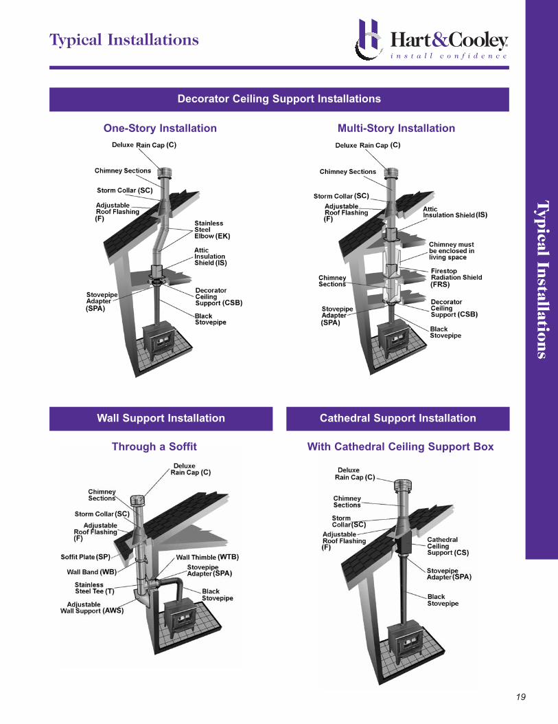
Typical Installations
Decorator Ceiling Support Installations
Wall Support Installation Cathedral Support Installation
One-Story Installation Multi-Story Installation
Through a Soffit With Cathedral Ceiling Support Box

Lim
ited
Lif
etim
e W
arra
nty
20
Limited Lifetime Warranty
LIMITED LIFETIME WARRANTYHart & Cooley, Inc. (“we,” “us,” “our”) warrants chimney and venting products to be free from defects in materialand workmanship for as long as the original consumer owns the system. For products installed after January 15,2007, for a period of ten (10) years from original installation, we will provide replacement product with a similar orlike quality of available product, free of charge excluding any installation costs. From the eleventh (11th) throughfifteenth (15th) years, we will provide replacement product to the original consumer at a cost of 75% off the publishedretail price in effect on the date the claim is received, excluding any installation costs. At expiration of the fifteen-(15) year term, we will provide replacement product to the original consumer at a cost of 50% off the published retailprice in effect on the date the claim is received, excluding any installation costs.
LIMITATIONS:- Products must be installed for their intended purpose.- Products must be connected to residential appliance listed with an accredited testing laboratory.WARNING: FAILURE TO INSTALL PRODUCTS ACCORDING TO THE MANUFACTURER’S INSTRUCTIONS WILLVOID ALL APPLICABLE WARRANTIES AND MAY RESULT IN FIRE, CARBON MONOXIDE POISONING OR DEATH.SEE OUR PRODUCT INSTALLATION INSTRUCTIONS FOR COMPLETE INSTRUCTIONS.
WARRANTY COVERAGE:All lengths, tees and elbows, and components are applicable to warranty coverage.
THIS LIMITED WARRANTY DOES NOT COVER:(a) any nonstainless base tee unit mounted or connected to an insulated chimney system;(b) costs (labor or otherwise**) associated with either removing a previously installed product, installing a
replacement product, transportation or return of a product, or transportation of replacement product;(c) damage to the finish of products caused by the use of improper solvents/chemicals or improper cleaning methods;(d) damage resulting from failure to reasonably clean, care for, or maintain products in accordance with our
installation instructions/recommendations;(e) damage (to products, appliances or structure) based on or resulting from improper installation or repair, misuse
or abuse (including, but not limited to, excessive or improper operating condition), or alteration or adjustmentother than in conformity with our installation instructions and specifications, whether performed by a contractor,service company, technician, or yourself;
(f) any products that have been moved from their original installation site.(g) damage caused by burning driftwood, garbage, or any other prohibitive material in the appliance served by the
chimney(h) damage that results from accidents such as fire, flood, high winds, “acts of God,” or any other contingency
beyond our control.
**Due to the wide variance in installation practices and other conditions beyond our control, we do notguarantee or in any way warrant the installation of chimney and venting products.
CLAIM PROCEDURE:If you believe that a product is defective, notify us in writing at the following location.
Hart & Cooley, Inc.Attn: Warranty Claims5030 Corporate Exchange Blvd. SEGrand Rapids, MI 49512800.433.6341 p800.223.8461 fwww.hartandcooley.com
Notification should include a description of the product, model and serial number (if applicable), and a description ofthe product defect. Upon receipt of a written claim under this limited warranty and evidence of the date of purchaseor installation, at our option and in our sole discretion, we will provide replacement product with similar or likequality of available product excluding any installation costs. We reserve the right to inspect or investigate anywarranty claims prior to determining whether to provide replacement product. If, as determined by us that repair orreplacement of the product is not commercially practicable or cannot be completed in a timely manner, we mayrefund the prorated purchase price paid for the product upon verification by providing a copy of your invoice orreceipt of bill of sale.

Check out other quality Hart & Cooley products...
To order any of the above catalogs, please contact Customer Service toll-free at 800.433.6341.
Form No. 010051
Form No. 010054Form No. 851095
Form No. 010050
Form No. 851367Form No. 851369
Form No. 851431

©2009 Hart & Cooley, Inc. All rights reserved Form No. 851343 1M 04/2009 Printed in U.S.A.