8521.11--10 actelec 3 to 1600 electric actuators · 8521.11--10 actelec 3 to 1600 electric...
TRANSCRIPT
Technical leaflet8521.11--10 ACTELEC 3 to 1600 electric actuators
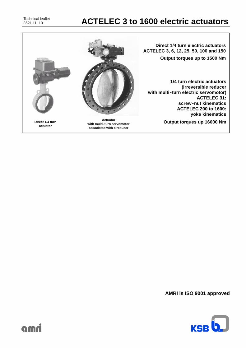
Direct 1/4 turn electric actuatorsACTELEC 3, 6, 12, 25, 50, 100 and 150
1/4 turn electric actuators(irreversible reducer
with multi--turn electric servomotor)ACTELEC 31:
screw--nut kinematicsACTELEC 200 to 1600:
yoke kinematics
Output torques up 16000 NmDirect 1/4 turnactuator
Actuatorwith multi--turn servomotorassociated with a reducer
Output torques up to 1500 Nm
AMRI is ISO 9001 approved

ACTELEC 3 to 1600electric actuators
2
Summary
Page
-- General features -- Prduction range 3
-- Construction: Basic equipment -- Other constructions -- Power supply -- Options on request 4
-- Directs 1/4 turn actuators ACTELEC 3 to 150: Manufacturing range -- Characteristics 5
-- Directs 1/4 turn actuators ACTELEC 3 to 150: On--off function, basic wiring diagram 6
-- Directs 1/4 turn actuators ACTELEC 3 to 150: On--off function, wiring diagram for integral control version 7
-- Directs 1/4 turn actuators ACTELEC 3 to 150: Throttling duty with 4--20 mA positioner, wiring diagram 8
-- Directs 1/4 turn actuators ACTELEC 3 to 150: Overall dimensions and weight 9
-- 1/4 turn actuators ACTELEC 31 to 1600: Manufacturing range -- Characteristics 10
-- 1/4 turn actuators ACTELEC 31 to 1600: On--off function, basic wiring diagram 11
-- 1/4 turn actuators ACTELEC 31 to 1600: On--off function, wiring diagram for integral control version 12
-- 1/4 turn actuators ACTELEC 31 to 1600: Throttling duty with 4--20 mA positioner, wiring diagram 13
-- 1/4 turn actuators ACTELEC 31 to 1600: ACTELEC 31 construction 15
-- 1/4 turn actuators ACTELEC 31 to 1600: ACTELEC 200 to 1600 construction 16
-- 1/4 turn actuators ACTELEC 31 to 1600: Overall dimensions and weight 17
-- 1/4 turn actuators ACTELEC 31 to 1600: Mounting on valve 18
ACTELEC 3 to 1600electric actuators
3
General features
The range of ACTELEC series electric actuators developed and manufactured by KSB--AMRI covers output torque values up to16000 Nm.Theseactuators havebeendesigned forall applications and for theoperationofany type ¼ turnvalves (centredor doubleeccentricdisc valves, ball valves,...).
The mounting interface is in accordance with ISO 5211 standard.Equipped with an interchangeable insert, they can be easily fitted on different valve shaft (square end, flat end, key, ...).The actuator is mounted directly or by means of an adaptator onto the valve mounting plate.
This range is constituted in two series:-- direct ¼ turn actuators, with irreversible kinematics, covering output torques up to 1500 Nm,-- ¼ turn actuators, with irreversible kinematics reducer associated with a multi--turn electric servomotor, covering output torques
up to 16000 Nm.
Protection
They are hose and fine dust proof and are protected against accidental immersion: protection degree IP 67.Motor: insulation class F.
External coating
Direct ¼ turn actuators:epoxy paint, thickness 60 ←m,color grey.
Actuators with reducer and electric servomotor:-- reducer: polyurethane paint, thickness 80 ←m, color dark grey RAL 7016,-- electric servomotor: polyurethane paint, thickness 80 ←m, color grey RAL 9007.
Working temperature range
From --20° C up to +70° C.
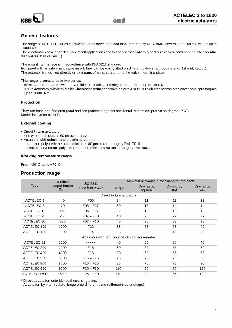
Production range
Nominal ISO 5211Maximal allowable dimensions for the shaft
TypeNominal
output torque(Nm)
ISO 5211mounting plate* Height Driving by
squareDriving by
flatDriving by
keyDirect ¼ turn actuators
ACTELEC 3 40 F05 24 11 11 12ACTELEC 6 70 F05 -- F07 30 16 14 14
ACTELEC 12 150 F05 -- F07 32 19 19 18ACTELEC 25 250 F07 -- F10 40 25 22 22ACTELEC 50 520 F07 -- F10 45 25 22 22
ACTELEC 100 1000 F12 55 36 36 42ACTELEC 150 1500 F14 65 50 46 50
Actuators with reducer and electric servomotorACTELEC 31 1000 ---------- 40 36 36 40
ACTELEC 200 2000 F16 80 60 55 72ACTELEC 400 4000 F16 80 60 55 72ACTELEC 500 5000 F16 -- F25 95 70 75 80ACTELEC 800 8000 F16 -- F25 95 70 75 80ACTELEC 950 9500 F25 -- F30 110 90 85 120
ACTELEC 1600 16000 F25 -- F30 110 90 85 120
* Direct adaptation onto identical mounting plate.Adaptation by intermediate flange onto different plate (different size or shape).
ACTELEC 3 to 1600electric actuators
4
Construction
Construction and basic equipmentsIn standard version, ACTELEC electric actuators are designed to ensure the on--off function, intermittent duty S2 15 mn.Remote electric control.
Basic equipments
Electric motor protection by:-- integrated thermic protection,-- 2 travel limit microswitches (1 microswitch on opening position and 1 on closure position)-- torque limit system (except on ACTELEC 3, 6 and 12 actuators).
Heating resistance anti--condensation. Manual emergency control by handwheel. Position indication. Mechanical adjustable travel stop(s).
Other constructions
Motor for continuous duty -- Repetitive startings (S4 -- 1200 startings/hour). Throttling duty with 4--20 mA integrated positioner. Integral electric control and remote control. Explosion--proof protection EExe.
Power supply
Standard version :-- 3--phase 230 V / 400 V -- 50 Hz a. c.,-- 1--phase 230 V -- 50 Hz a. c.
On request :24 or 48 V d. c.
Options on request (please consult us)
Additional microswitches adjustable on the whole travel for remote position signalisation (limit position and/or intermediateposition).
Microswitches coupled with torque limiter. Position transmission by potentiometer 1000 τ or electronic transmitter 4--20 mA. Blinker. Communication interface -- Intelligence -- Fieldbus. Other power supplies.
ACTELEC 3 to 1600electric actuators
5
Direct 1/4 turn actuators: ACTELEC 3 to 150
ACTELEC 3 to 150 electric actuators are based on a direct ¼ turn servomotor with a mounting interface in accordance withISO 5211 standard.These actuators are available in on--off function or throttling duties.
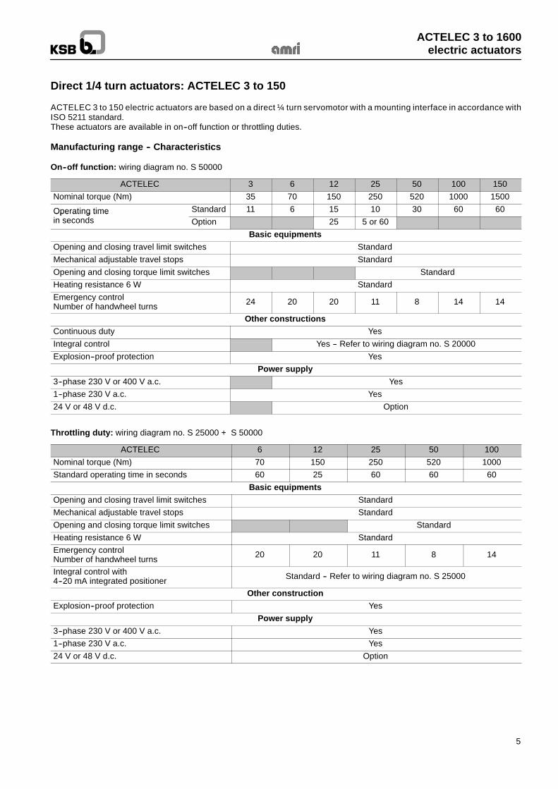
Manufacturing range -- Characteristics
On--off function: wiring diagram no. S 50000
ACTELEC 3 6 12 25 50 100 150Nominal torque (Nm) 35 70 150 250 520 1000 1500
Operating time Standard 11 6 15 10 30 60 60Operating timein seconds Option 25 5 or 60
Basic equipmentsOpening and closing travel limit switches StandardMechanical adjustable travel stops StandardOpening and closing torque limit switches StandardHeating resistance 6 W StandardEmergency controlNumber of handwheel turns 24 20 20 11 8 14 14
Other constructionsContinuous duty YesIntegral control Yes -- Refer to wiring diagram no. S 20000Explosion--proof protection Yes
Power supply3--phase 230 V or 400 V a.c. Yes1--phase 230 V a.c. Yes24 V or 48 V d.c. Option
Throttling duty: wiring diagram no. S 25000 + S 50000
ACTELEC 6 12 25 50 100Nominal torque (Nm) 70 150 250 520 1000Standard operating time in seconds 60 25 60 60 60
Basic equipmentsOpening and closing travel limit switches StandardMechanical adjustable travel stops StandardOpening and closing torque limit switches StandardHeating resistance 6 W StandardEmergency controlNumber of handwheel turns 20 20 11 8 14
Integral control with4--20 mA integrated positioner Standard -- Refer to wiring diagram no. S 25000
Other constructionExplosion--proof protection Yes
Power supply3--phase 230 V or 400 V a.c. Yes1--phase 230 V a.c. Yes24 V or 48 V d.c. Option
ACTELEC 3 to 1600electric actuators
6
Direct 1/4 turn actuators: ACTELEC 3 to 150
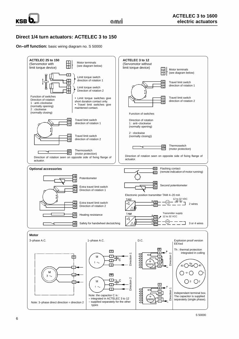
On--off function: basic wiring diagram no. S 50000
ACTELEC 25 to 150(Servomotor withlimit torque device)
Motor terminals(see diagram below)
Limit torque switchdirection of rotation 1
Limit torque switchDirection of rotation 2
Motor terminals(see diagram below)
Travel limit switchdirection of rotation 1
Travel limit switchdirection of rotation 2
ACTELEC 3 to 12(Servomotor withoutlimit torque device)
Limit torque switches giveshort duration contact only. Travel limit switches givemaintened contact.
Function of switchesDirection of rotation1 : anti--clockwise(normally opening)2 : clockwise(normally closing)
Travel limit switchdirection of rotation 1
Travel limit switchdirection of rotation 2
Function of switches
Direction of rotation1 : anti--clockwise(normally opening)
2 : clockwise(normally closing))
Thermoswitch(motor protection)
Thermoswitch(motor protection)
Direction of rotation seen on opposite side of fixing flange ofactuator.
Direction of rotation seen on opposite side of fixing flange ofactuator.
Optional accessories
Potentiometer
Heating resistance
Safety for handwheel declutching
Extra travel limit switchDirection of rotation 2
Extra travel limit switchDirection of rotation 1
Flashing contact(remote indication of motor running)
Second potentiometer
Electronic position transmitter TAM 4--20 mA12 to 32 VDC
2 wires
Transmitter supply12 to 32 VCC
3 or 4 wires
Motor
3--phase A.C. 1--phase A.C. D.C. Explosion proof versionEEXed
Th : thermal protectionintegrated in coiling
Dire
ctio
n1
Dire
ctio
n1Dire
ctio
n2
Dire
ctio
n2
Independant terminal box.The capacitor is suppliedseparately (single phase).
Note: the capacitor C is :-- integrated in ACTELEC 3 to 12-- supplied separately for the other
typesNote: 3--phase direct direction = direction 2
S 50000
ACTELEC 3 to 1600electric actuators
7
Direct 1/4 turn actuators: ACTELEC 3 to 150
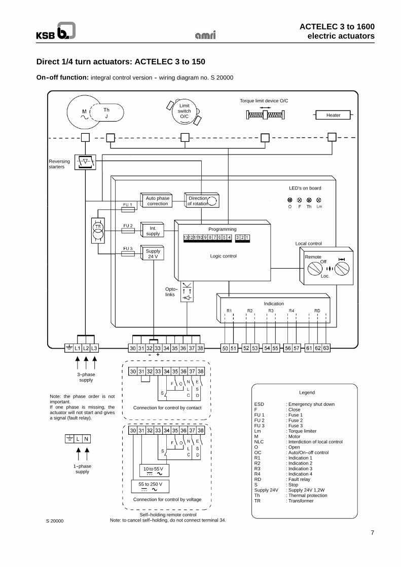
On--off function: integral control version -- wiring diagram no. S 20000
LimitswitchO/C
Torque limit device O/C
Heater
LED’s on board
Directionof rotation
Auto phasecorrection
Int.supply
Supply24 V
Reversingstarters
Logic control
Programming
Local control
RemoteOff
Loc.
Indication
Opto--links
3--phasesupply
Note: the phase order is notimportant.If one phase is missing, theactuator will not start and givesa signal (fault relay).
Connection for control by contact
Connection for control by voltage
1--phasesupply
Legend
ESD : Emergency shut downF : CloseFU 1 : Fuse 1FU 2 : Fuse 2FU 3 : Fuse 3Lm : Torque limiterM : MotorNLC : Interdiction of local controlO : OpenOC : Auto/On--off controlR1 : Indication 1R2 : Indication 2R3 : Indication 3R4 : Indication 4RD : Fault relayS : StopSupply 24V : Supply 24V 1,2WTh : Thermal protectionTR : Transformer
Self--holding remote controlNote: to cancel self--holding, do not connect terminal 34.S 20000
10 to 55 V
55 to 250 V
ACTELEC 3 to 1600electric actuators
8
Direct 1/4 turn actuators: ACTELEC 3 to 150
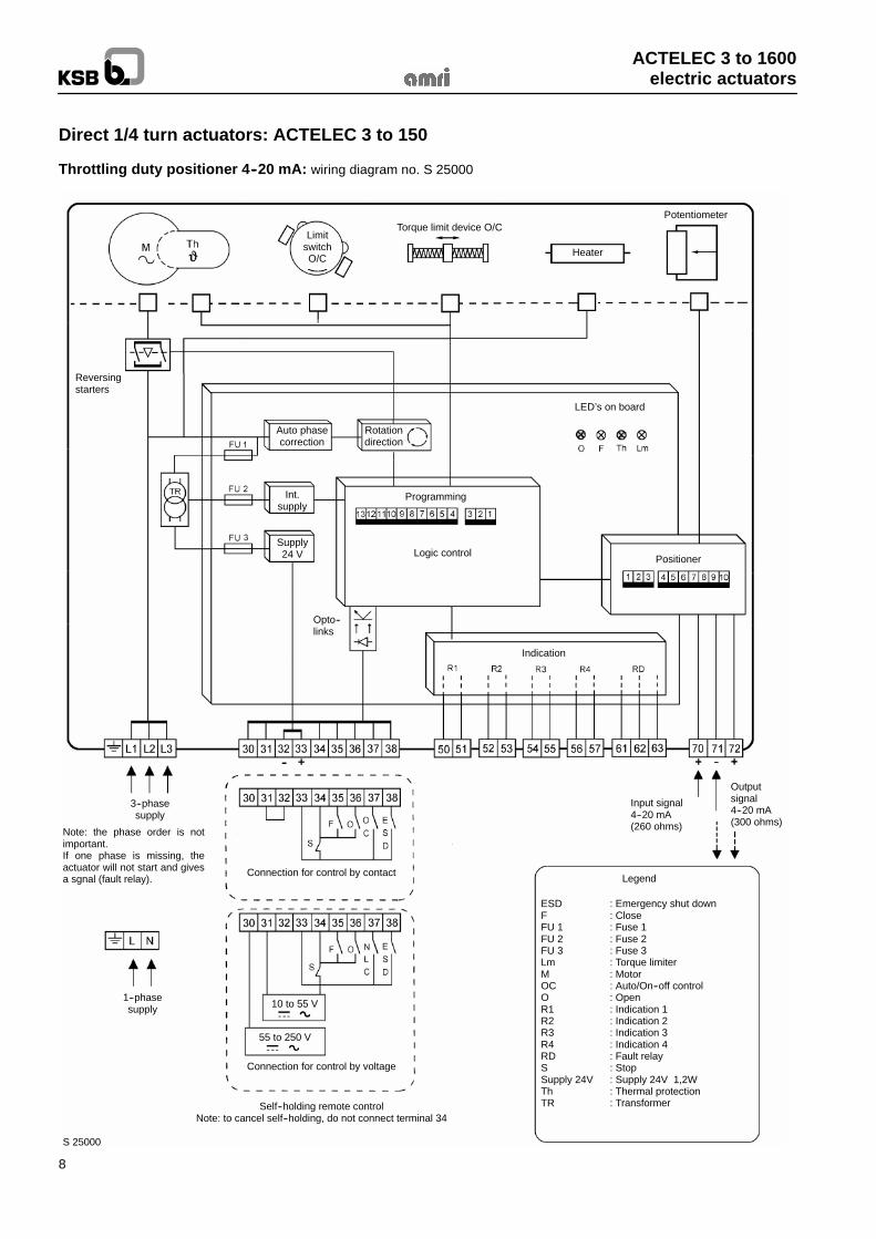
Throttling duty positioner 4--20 mA: wiring diagram no. S 25000
LimitswitchO/C
Torque limit device O/C
Heater
Potentiometer
Reversingstarters
Auto phasecorrection
Rotationdirection
LED’s on board
Int.supply
Supply24 V
Programming
Logic controlPositioner
Indication
Opto--links
3--phasesupply
1--phasesupply
Note: the phase order is notimportant.If one phase is missing, theactuator will not start and givesa sgnal (fault relay).
Connection for control by contact
Connection for control by voltage
Self--holding remote controlNote: to cancel self--holding, do not connect terminal 34
S 25000
10 to 55 V
55 to 250 V
Input signal4--20 mA(260 ohms)
Outputsignal4--20 mA(300 ohms)
ESD : Emergency shut downF : CloseFU 1 : Fuse 1FU 2 : Fuse 2FU 3 : Fuse 3Lm : Torque limiterM : MotorOC : Auto/On--off controlO : OpenR1 : Indication 1R2 : Indication 2R3 : Indication 3R4 : Indication 4RD : Fault relayS : StopSupply 24V : Supply 24V 1,2WTh : Thermal protectionTR : Transformer
Legend
ACTELEC 3 to 1600electric actuators
9
Direct 1/4 turn actuators: ACTELEC 3 to 150
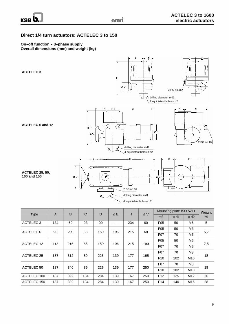
On--off function -- 3--phase supplyOverall dimensions (mm) and weight (kg)
ACTELEC 3
drilling diameter ø d14 equidistant holes ø d2
2 PG no.16
ACTELEC 6 and 12
drilling diameter ø d1
4 equidistant holes ø d2
2 PG no.16
ACTELEC 25, 50,100 and 150
drilling diameter ø d1
4 equidistant holes ø d2
2 PG no.16
Type A B C D ø E H ø VMounting plate ISO 5211 WeightType A B C D ø E H ø Vref. ø d1 ø d2
Weightkg
ACTELEC 3 134 59 93 90 ------ 234 60 F05 50 M6 5
ACTELEC 6 90 200 65 150 106 215 60F05 50 M6
5 7ACTELEC 6 90 200 65 150 106 215 60F07 70 M8
5,7
ACTELEC 12 112 215 65 150 106 215 100F05 50 M6
7 5ACTELEC 12 112 215 65 150 106 215 100F07 70 M8
7,5
ACTELEC 25 187 312 89 226 139 177 165F07 70 M8
18ACTELEC 25 187 312 89 226 139 177 165F10 102 M10
18
ACTELEC 50 187 340 89 226 139 177 250F07 70 M8
18ACTELEC 50 187 340 89 226 139 177 250F10 102 M10
18
ACTELEC 100 187 392 134 284 139 167 250 F12 125 M12 26
ACTELEC 150 187 392 134 284 139 167 250 F14 140 M16 28
ACTELEC 3 to 1600electric actuators
10
ACTELEC 31 to 1600 1/4 turn actuators
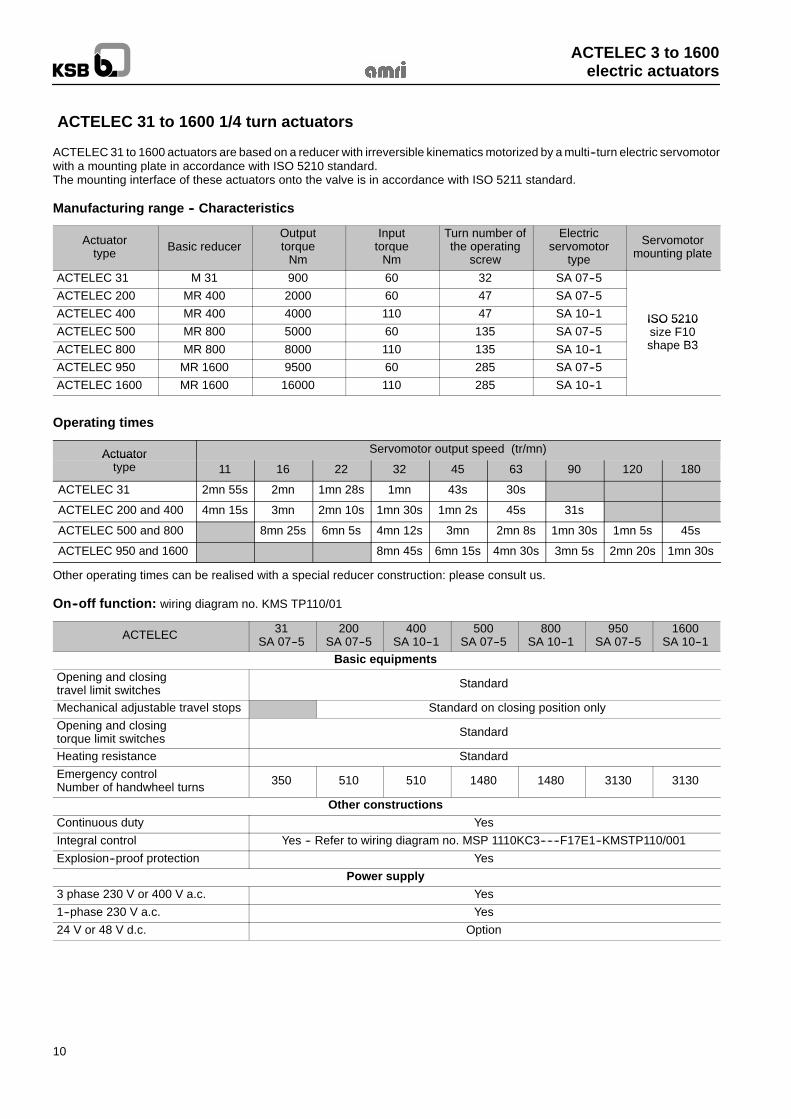
ACTELEC 31 to 1600 actuators are based on a reducer with irreversible kinematics motorized by a multi--turn electric servomotorwith a mounting plate in accordance with ISO 5210 standard.The mounting interface of these actuators onto the valve is in accordance with ISO 5211 standard.
Manufacturing range -- Characteristics
Actuatortype Basic reducer
Outputtorque
Nm
Inputtorque
Nm
Turn number ofthe operating
screw
Electricservomotor
type
Servomotormounting plate
ACTELEC 31 M 31 900 60 32 SA 07--5ACTELEC 200 MR 400 2000 60 47 SA 07--5ACTELEC 400 MR 400 4000 110 47 SA 10--1 ISO 5210ACTELEC 500 MR 800 5000 60 135 SA 07--5
ISO 5210size F10h B3ACTELEC 800 MR 800 8000 110 135 SA 10--1 shape B3
ACTELEC 950 MR 1600 9500 60 285 SA 07--5ACTELEC 1600 MR 1600 16000 110 285 SA 10--1
Operating times
Actuator Servomotor output speed (tr/mn)Actuatortype 11 16 22 32 45 63 90 120 180
ACTELEC 31 2mn 55s 2mn 1mn 28s 1mn 43s 30s
ACTELEC 200 and 400 4mn 15s 3mn 2mn 10s 1mn 30s 1mn 2s 45s 31s
ACTELEC 500 and 800 8mn 25s 6mn 5s 4mn 12s 3mn 2mn 8s 1mn 30s 1mn 5s 45s
ACTELEC 950 and 1600 8mn 45s 6mn 15s 4mn 30s 3mn 5s 2mn 20s 1mn 30s
Other operating times can be realised with a special reducer construction: please consult us.
On--off function: wiring diagram no. KMS TP110/01
ACTELEC 31SA 07--5
200SA 07--5
400SA 10--1
500SA 07--5
800SA 10--1
950SA 07--5
1600SA 10--1
Basic equipmentsOpening and closingtravel limit switches Standard
Mechanical adjustable travel stops Standard on closing position onlyOpening and closingtorque limit switches Standard
Heating resistance StandardEmergency controlNumber of handwheel turns 350 510 510 1480 1480 3130 3130
Other constructionsContinuous duty YesIntegral control Yes -- Refer to wiring diagram no. MSP 1110KC3------F17E1--KMSTP110/001Explosion--proof protection Yes
Power supply3 phase 230 V or 400 V a.c. Yes1--phase 230 V a.c. Yes24 V or 48 V d.c. Option
ACTELEC 3 to 1600electric actuators
11
ACTELEC 31 to 1600 1/4 turn actuators
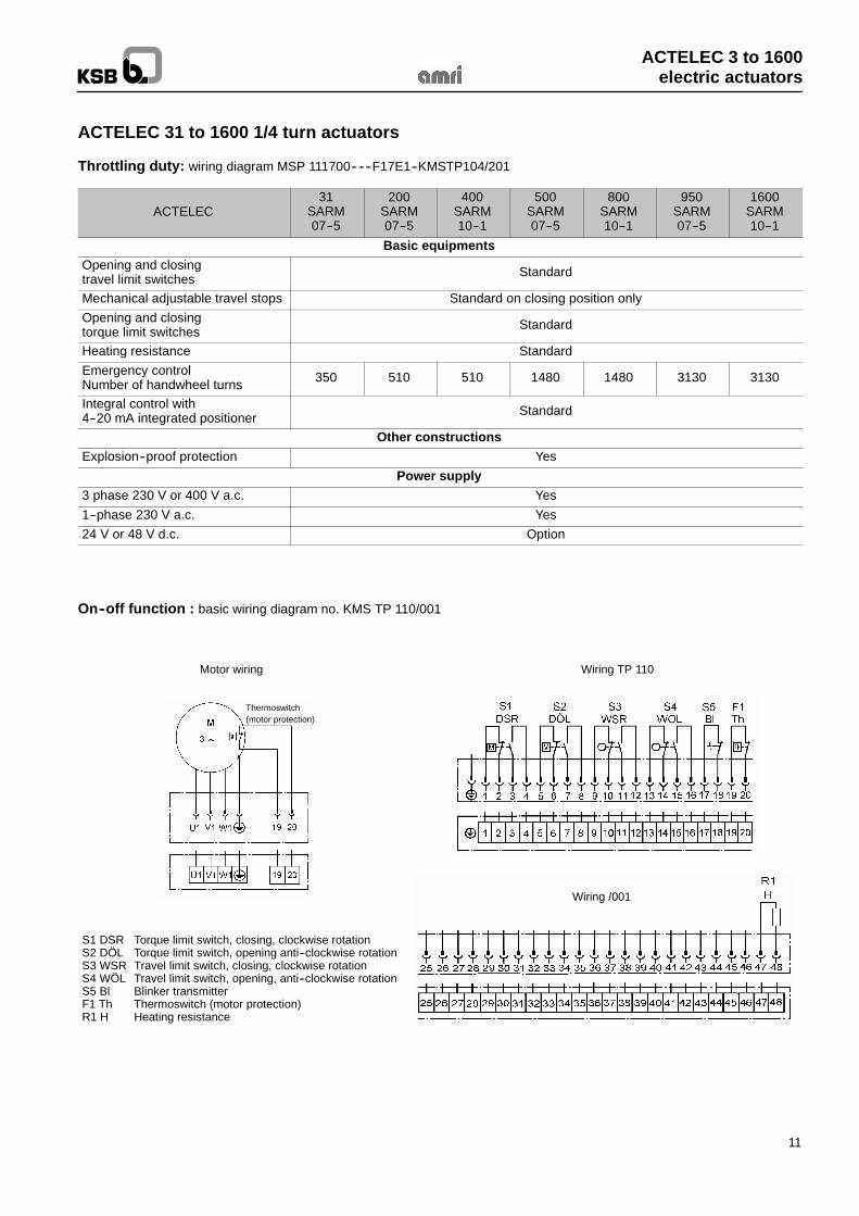
Throttling duty: wiring diagram MSP 111700------F17E1--KMSTP104/201
ACTELEC31
SARM07--5
200SARM07--5
400SARM10--1
500SARM07--5
800SARM10--1
950SARM07--5
1600SARM10--1
Basic equipmentsOpening and closingtravel limit switches Standard
Mechanical adjustable travel stops Standard on closing position onlyOpening and closingtorque limit switches Standard
Heating resistance StandardEmergency controlNumber of handwheel turns 350 510 510 1480 1480 3130 3130
Integral control with4--20 mA integrated positioner Standard
Other constructionsExplosion--proof protection Yes
Power supply3 phase 230 V or 400 V a.c. Yes1--phase 230 V a.c. Yes24 V or 48 V d.c. Option
On--off function : basic wiring diagram no. KMS TP 110/001
Wiring /001
S1 DSR Torque limit switch, closing, clockwise rotationS2 DÖL Torque limit switch, opening anti--clockwise rotationS3 WSR Travel limit switch, closing, clockwise rotationS4 WÖL Travel limit switch, opening, anti--clockwise rotationS5 Bl Blinker transmitterF1 Th Thermoswitch (motor protection)R1 H Heating resistance
Motor wiring Wiring TP 110
Thermoswitch(motor protection)
ACTELEC 3 to 1600electric actuators
12
ACTELEC 31 to 1600 1/4 turn actuators
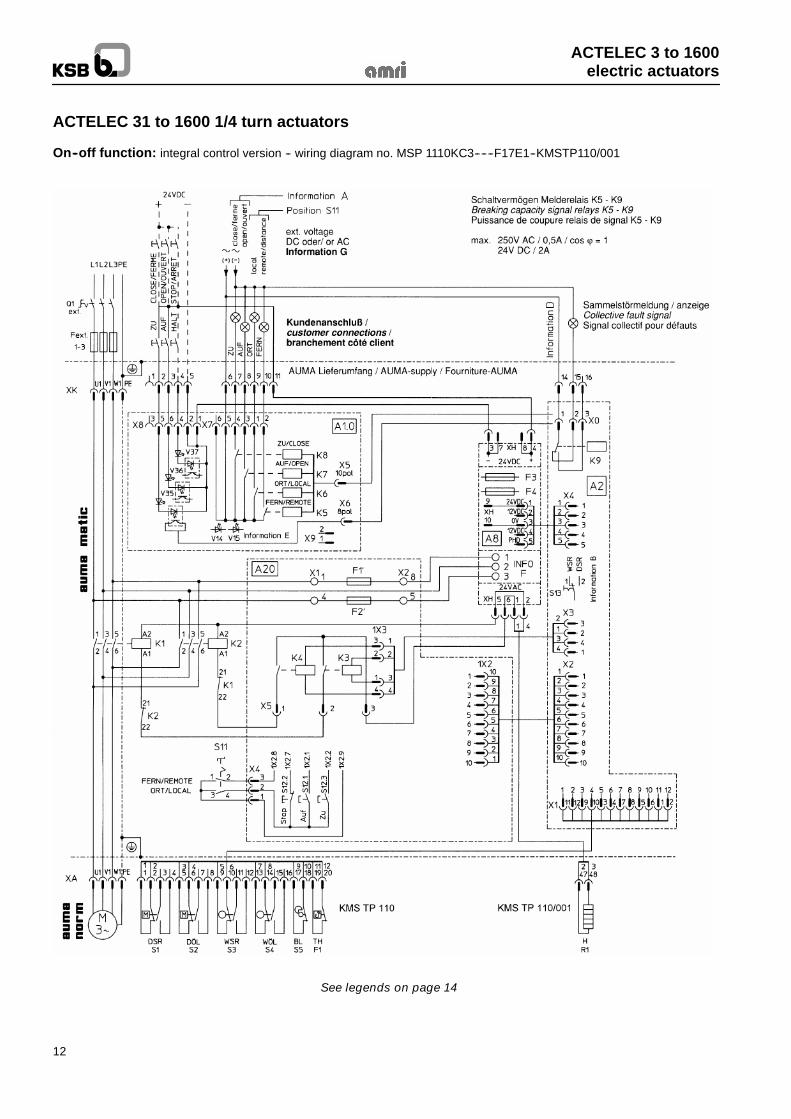
On--off function: integral control version -- wiring diagram no. MSP 1110KC3------F17E1--KMSTP110/001
See legends on page 14
ACTELEC 3 to 1600electric actuators
13
ACTELEC 31 à 1600 1/4 turn actuators
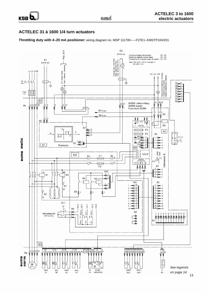
Throttling duty with 4--20 mA positioner: wiring diagram no. MSP 111700------F27E1--KMSTP104/201
See legends
on page 14
ACTELEC 3 to 1600electric actuators
14
ACTELEC 31 to 1600 1/4 turn actuators
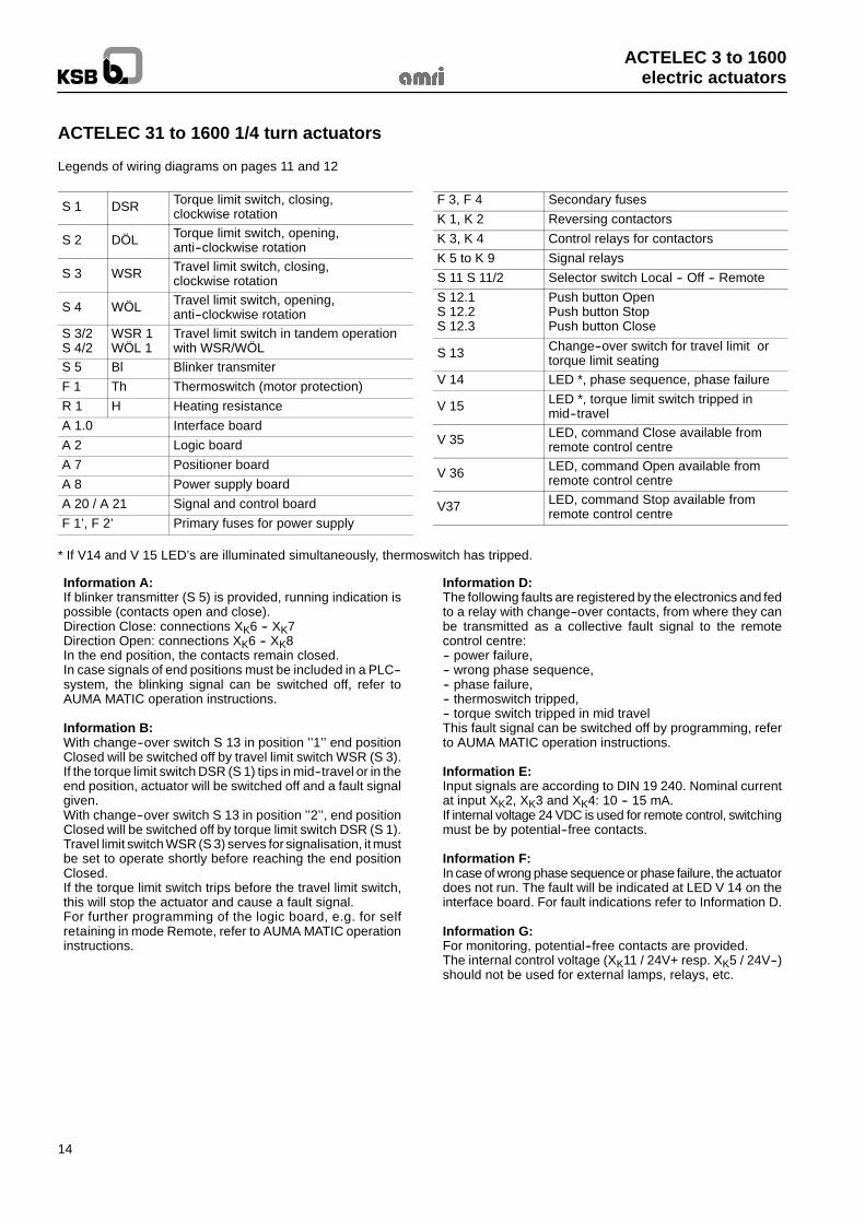
Legends of wiring diagrams on pages 11 and 12
S 1 DSR Torque limit switch, closing,clockwise rotation
S 2 DÖL Torque limit switch, opening,anti--clockwise rotation
S 3 WSR Travel limit switch, closing,clockwise rotation
S 4 WÖL Travel limit switch, opening,anti--clockwise rotation
S 3/2S 4/2
WSR 1WÖL 1
Travel limit switch in tandem operationwith WSR/WÖL
S 5 Bl Blinker transmiterF 1 Th Thermoswitch (motor protection)R 1 H Heating resistanceA 1.0 Interface boardA 2 Logic boardA 7 Positioner boardA 8 Power supply boardA 20 / A 21 Signal and control boardF 1’, F 2’ Primary fuses for power supply
F 3, F 4 Secondary fusesK 1, K 2 Reversing contactorsK 3, K 4 Control relays for contactorsK 5 to K 9 Signal relaysS 11 S 11/2 Selector switch Local -- Off -- RemoteS 12.1S 12.2S 12.3
Push button OpenPush button StopPush button Close
S 13 Change--over switch for travel limit ortorque limit seating
V 14 LED *, phase sequence, phase failure
V 15 LED *, torque limit switch tripped inmid--travel
V 35 LED, command Close available fromremote control centre
V 36 LED, command Open available fromremote control centre
V37 LED, command Stop available fromremote control centre
* If V14 and V 15 LED’s are illuminated simultaneously, thermoswitch has tripped.
Information A:If blinker transmitter (S 5) is provided, running indication ispossible (contacts open and close).Direction Close: connections XK6 -- XK7Direction Open: connections XK6 -- XK8In the end position, the contacts remain closed.In case signals of end positions must be included in a PLC--system, the blinking signal can be switched off, refer toAUMA MATIC operation instructions.
Information B:With change--over switch S 13 in position ’’1’’ end positionClosed will be switched off by travel limit switch WSR (S 3).If the torque limit switch DSR (S 1) tips in mid--travel or in theend position, actuator will be switched off and a fault signalgiven.With change--over switch S 13 in position ’’2’’, end positionClosed will be switched off by torque limit switch DSR (S 1).Travel limit switch WSR (S 3) serves for signalisation, it mustbe set to operate shortly before reaching the end positionClosed.If the torque limit switch trips before the travel limit switch,this will stop the actuator and cause a fault signal.For further programming of the logic board, e.g. for selfretaining in mode Remote, refer to AUMA MATIC operationinstructions.
Information D:The following faults are registered by the electronics and fedto a relay with change--over contacts, from where they canbe transmitted as a collective fault signal to the remotecontrol centre:-- power failure,-- wrong phase sequence,-- phase failure,-- thermoswitch tripped,-- torque switch tripped in mid travelThis fault signal can be switched off by programming, referto AUMA MATIC operation instructions.
Information E:Input signals are according to DIN 19 240. Nominal currentat input XK2, XK3 and XK4: 10 -- 15 mA.If internal voltage 24 VDC is used for remote control, switchingmust be by potential--free contacts.
Information F:In case of wrong phase sequence or phase failure, the actuatordoes not run. The fault will be indicated at LED V 14 on theinterface board. For fault indications refer to Information D.
Information G:For monitoring, potential--free contacts are provided.The internal control voltage (XK11 / 24V+ resp. XK5 / 24V--)should not be used for external lamps, relays, etc.
ACTELEC 3 to 1600electric actuators
15
ACTELEC 31 to 1600 1/4 turn actuators
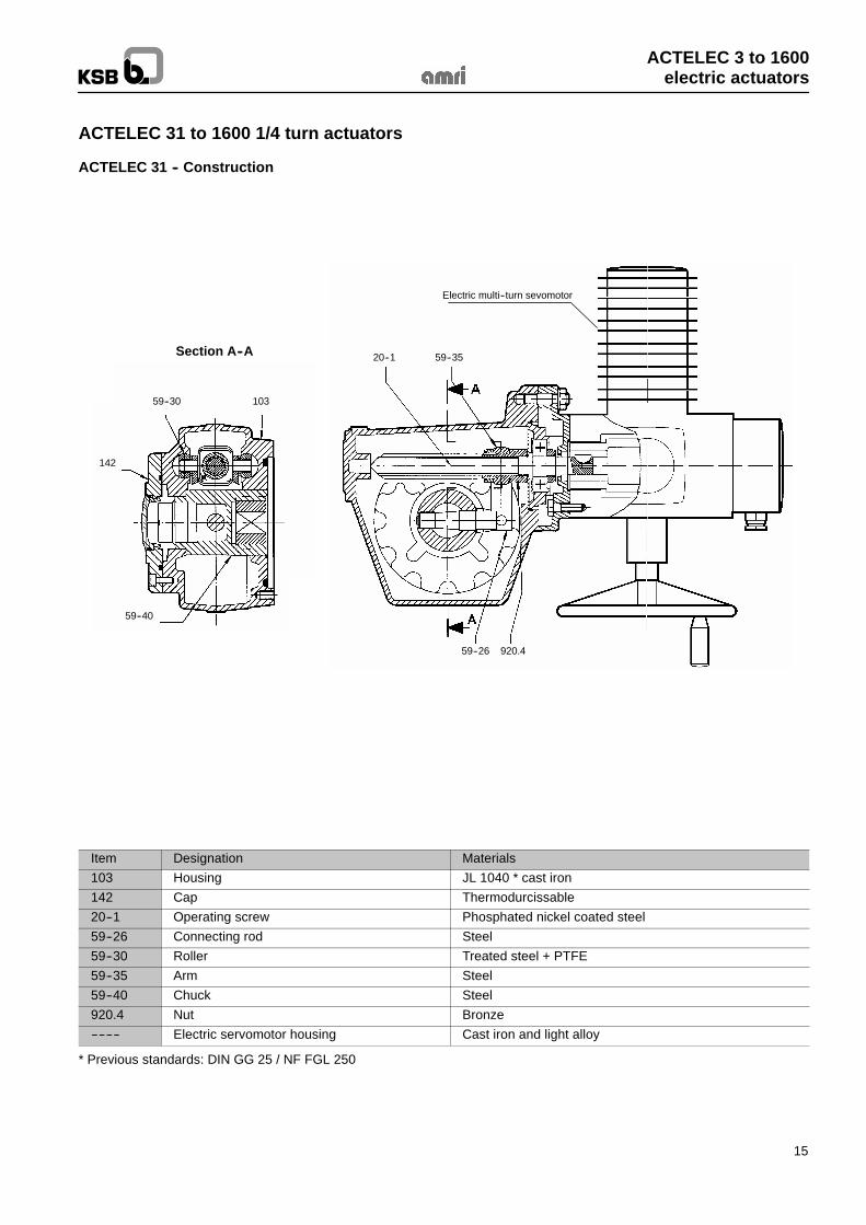
ACTELEC 31 -- Construction
Section A--A
59--30 103
142
59--40
20--1 59--35
59--26 920.4
Electric multi--turn sevomotor
Item Designation Materials103 Housing JL 1040 * cast iron142 Cap Thermodurcissable20--1 Operating screw Phosphated nickel coated steel59--26 Connecting rod Steel59--30 Roller Treated steel + PTFE59--35 Arm Steel59--40 Chuck Steel920.4 Nut Bronze-------- Electric servomotor housing Cast iron and light alloy
* Previous standards: DIN GG 25 / NF FGL 250
ACTELEC 3 to 1600electric actuators
16
ACTELEC 31 to 1600 1/4 turn actuators
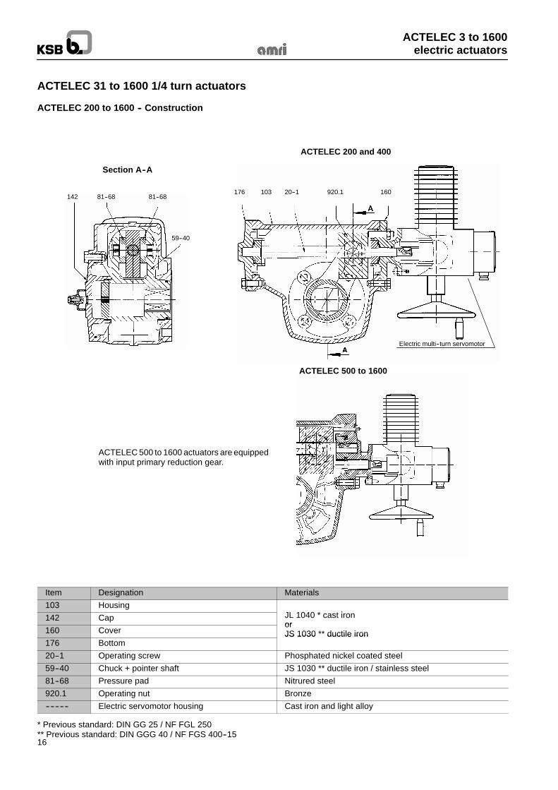
ACTELEC 200 to 1600 -- Construction
Section A--A
ACTELEC 500 to 1600 actuators are equippedwith input primary reduction gear.
ACTELEC 200 and 400
ACTELEC 500 to 1600
142 81--68 81--68
59--40
176 103 20--1 920.1 160
Electric multi--turn servomotor
Item Designation Materials103 Housing
JL 1040 * t i142 Cap JL 1040 * cast ironor
160 CoverorJS 1030 ** ductile iron
176 BottomJS 1030 ductile iron
20--1 Operating screw Phosphated nickel coated steel59--40 Chuck + pointer shaft JS 1030 ** ductile iron / stainless steel81--68 Pressure pad Nitrured steel920.1 Operating nut Bronze---------- Electric servomotor housing Cast iron and light alloy
* Previous standard: DIN GG 25 / NF FGL 250** Previous standard: DIN GGG 40 / NF FGS 400--15
ACTELEC 3 to 1600electric actuators
17
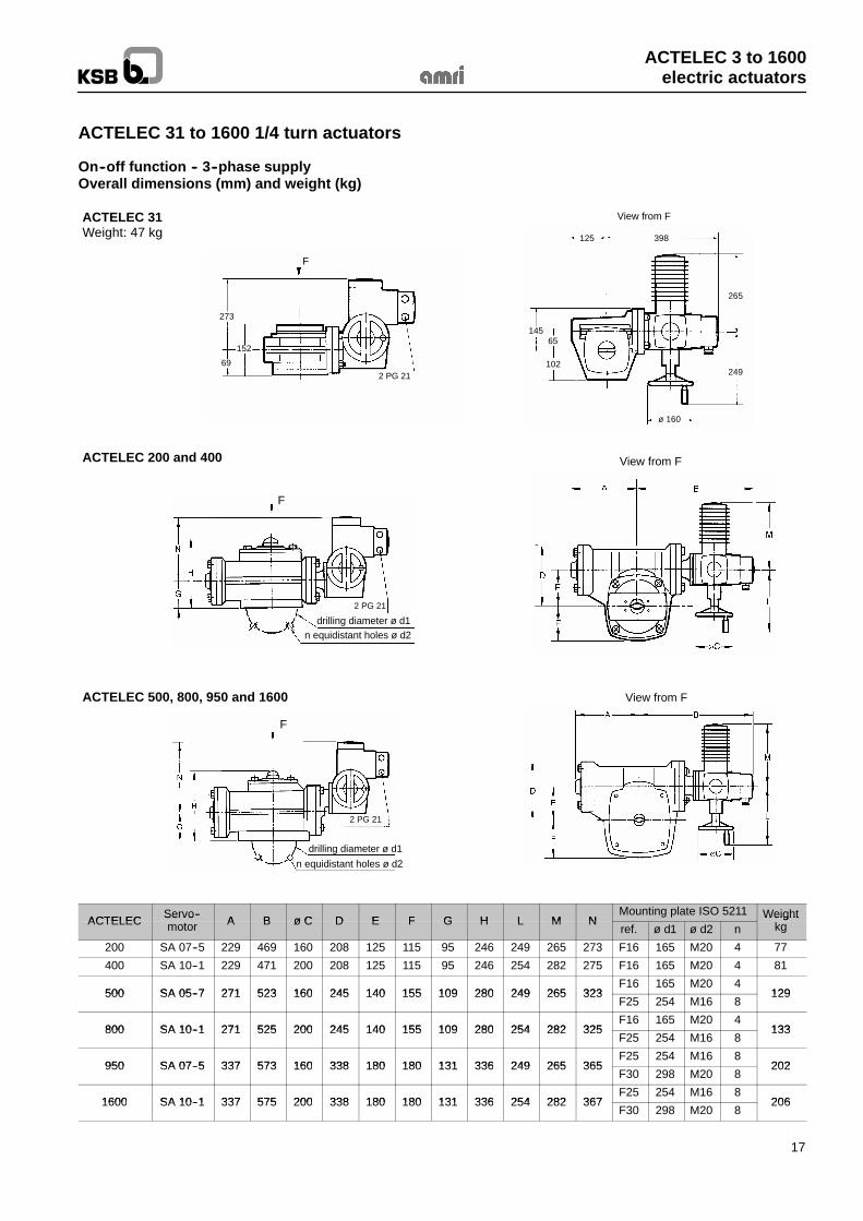
ACTELEC 31 to 1600 1/4 turn actuators
On--off function -- 3--phase supplyOverall dimensions (mm) and weight (kg)
ACTELEC 31Weight: 47 kg
View from F
273
69
152
F
2 PG 21
125 398
14565
102
ø 160
265
249
View from FACTELEC 200 and 400
n equidistant holes ø d2drilling diameter ø d1
2 PG 21
F
View from FACTELEC 500, 800, 950 and 1600
n equidistant holes ø d2drilling diameter ø d1
2 PG 21
F
ACTELEC Servo-- A B ø C D E F G H L M NMounting plate ISO 5211 WeightACTELEC Servo
motor A B ø C D E F G H L M Nref. ø d1 ø d2 n
Weightkg
200 SA 07--5 229 469 160 208 125 115 95 246 249 265 273 F16 165 M20 4 77
400 SA 10--1 229 471 200 208 125 115 95 246 254 282 275 F16 165 M20 4 81
500 SA 05--7 271 523 160 245 140 155 109 280 249 265 323F16 165 M20 4
129500 SA 05--7 271 523 160 245 140 155 109 280 249 265 323F25 254 M16 8
129
800 SA 10--1 271 525 200 245 140 155 109 280 254 282 325F16 165 M20 4
133800 SA 10--1 271 525 200 245 140 155 109 280 254 282 325F25 254 M16 8
133
950 SA 07--5 337 573 160 338 180 180 131 336 249 265 365F25 254 M16 8
202950 SA 07--5 337 573 160 338 180 180 131 336 249 265 365F30 298 M20 8
202
1600 SA 10--1 337 575 200 338 180 180 131 336 254 282 367F25 254 M16 8
2061600 SA 10--1 337 575 200 338 180 180 131 336 254 282 367F30 298 M20 8
206
ACTELEC 3 to 1600electric actuators
18
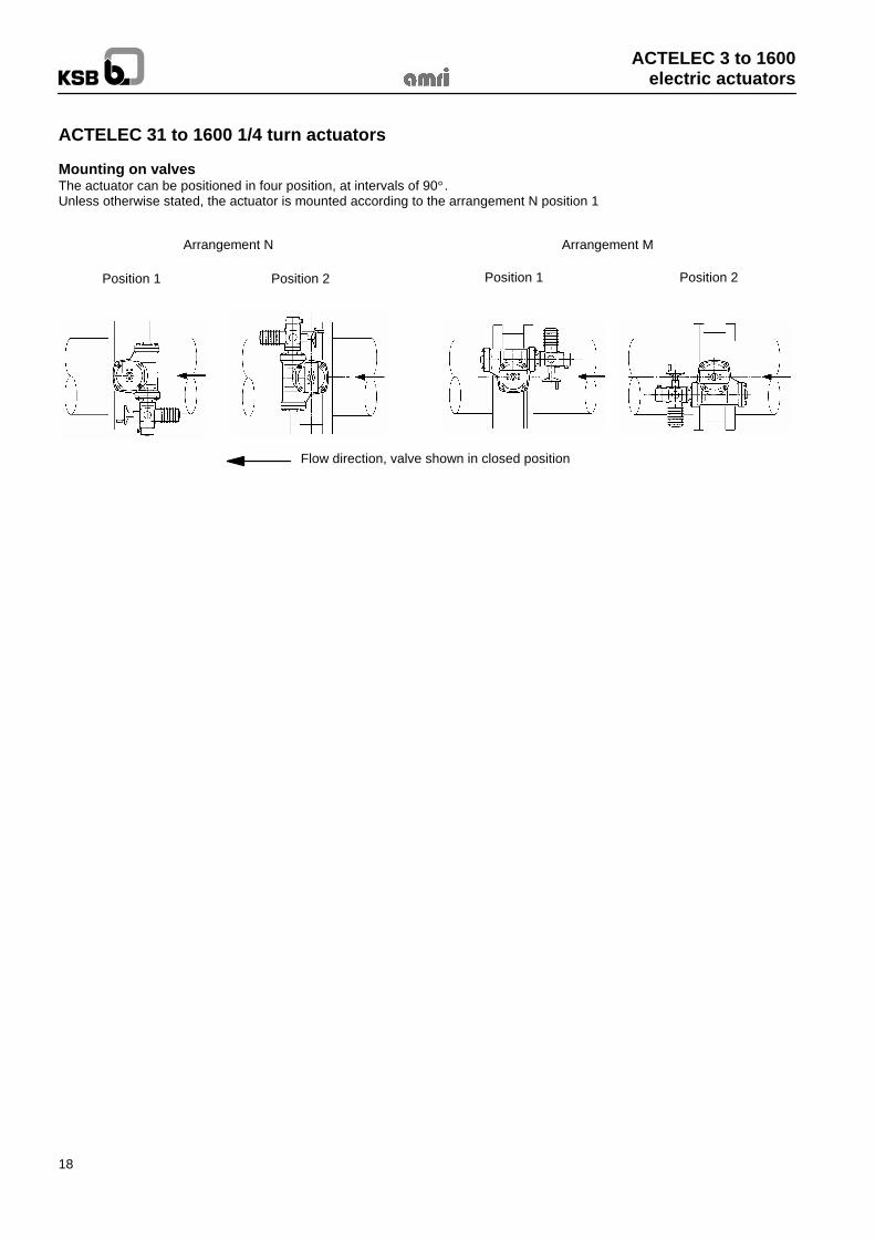
ACTELEC 31 to 1600 1/4 turn actuators
Mounting on valvesThe actuator can be positioned in four position, at intervals of 90° .Unless otherwise stated, the actuator is mounted according to the arrangement N position 1
Arrangement N Arrangement M
Position 1 Position 2 Position 1 Position 2
Flow direction, valve shown in closed position

ACTELEC 3 to 1600electric actuators
19

8521
.11-
101.
06.0
0Th
isle
afle
tis
notc
ontra
ctua
lan
dm
aybe
amen
ded
with
outn
otic
e
KSB - AMRI Phone: 33 5 53 92 44 00Z.I. de Gagnaire Fonsèche T/Fax: 33 5 53 92 44 01 Butterfly valves,F-24490 La Roche Chalais Web: http://www.ksbgroup.com Actuators and systems