8903/pb profibus communications interface - sds drives · 8903/pb profibus communications interface...
TRANSCRIPT

8903/PB Profibus Communications Interface
Technical Manual HA469267U001 Issue 3
Compatible with 890 Firmware Version 1.4 onwards
© Copyright 2007 Parker SSD Drives, a division of Parker Hannifin Ltd.
All rights strictly reserved. No part of this document may be stored in a retrieval system, or transmitted in any form or by any means to persons not employed by a Parker SSD Drives company without written permission from Parker SSD Drives, a division of Parker Hannifin Ltd . Although every effort has been taken to ensure the accuracy of this document it may be necessary, without notice, to make amendments or correct omissions. Parker SSD Drives cannot accept responsibility for damage, injury, or expenses resulting therefrom.

WARRANTY Parker SSD Drives warrants the goods against defects in design, materials and workmanship for the period of 12 months from the date of delivery on the
terms detailed in Parker SSD Drives Standard Conditions of Sale IA058393C.
Parker SSD Drives reserves the right to change the content and product specification without notice.
Cont.3
Requirements IMPORTANT: Please read this information BEFORE installing the equipment.
Intended Users This manual is to be made available to all persons who are required to install, configure or service equipment described herein, or any other associated operation.
The information given is intended to highlight safety issues, EMC considerations, and to enable the user to obtain maximum benefit from the equipment.
Complete the following table for future reference detailing how the unit is to be installed and used.
INSTALLATION DETAILS
Model Number (see product label)
Where installed (for your own information)
Unit used as a: (refer to Certification for the Inverter)
Component Relevant Apparatus
Unit fitted: Wall-mounted Enclosure
Application Area The equipment described is intended for industrial motor speed control utilising AC induction or AC synchronous machines.
Personnel Installation, operation and maintenance of the equipment should be carried out by qualified personnel. A qualified person is someone who is technically competent and familiar with all safety information and established safety practices; with the installation process, operation and maintenance of this equipment; and with all the hazards involved.
Product Warnings
Caution Risk of electric
shock
Caution Refer to
documentation
Earth/Ground Protective Conductor Terminal
Safety Information !

Cont.4
Hazards DANGER! - Ignoring the following may result in injury 1. This equipment can endanger life by exposure to
rotating machinery and high voltages.
2. The equipment must be permanently earthed due to the high earth leakage current, and the drive motor must be connected to an appropriate safety earth.
3. Ensure all incoming supplies are isolated before working on the equipment. Be aware that there may be more than one supply connection to the drive.
4. There may still be dangerous voltages present at power terminals (motor output, supply input phases, DC bus and the brake, where fitted) when the motor is at standstill or is stopped.
5. For measurements use only a meter to IEC 61010 (CAT III or higher). Always begin using the highest range. CAT I and CAT II meters must not be used on this product.
6. Allow at least 5 minutes for the drive's capacitors to discharge to safe voltage levels (<50V). Use the specified meter capable of measuring up to 1000V dc & ac rms to confirm that less than 50V is present between all power terminals and earth.
7. Unless otherwise stated, this product must NOT be dismantled. In the event of a fault the drive must be returned. Refer to "Routine Maintenance and Repair".
WARNING! - Ignoring the following may result in injury or damage to equipment
SAFETY Where there is conflict between EMC and Safety requirements, personnel safety shall always take precedence. • Never perform high voltage resistance checks on the
wiring without first disconnecting the drive from the circuit being tested.
• Whilst ensuring ventilation is sufficient, provide guarding and /or additional safety systems to prevent injury or damage to equipment.
• When replacing a drive in an application and before returning to use, it is essential that all user defined parameters for the product’s operation are correctly installed.
• All control and signal terminals are SELV, i.e. protected by double insulation. Ensure all external wiring is rated for the highest system voltage.
• Thermal sensors contained within the motor must have at least basic insulation.
• All exposed metalwork in the Inverter is protected by basic insulation and bonded to a safety earth.
• RCDs are not recommended for use with this product but, where their use is mandatory, only Type B RCDs should be used.
EMC • In a domestic environment this product may cause radio
interference in which case supplementary mitigation measures may be required.
• This equipment contains electrostatic discharge (ESD) sensitive parts. Observe static control precautions when handling, installing and servicing this product.
• This is a product of the restricted sales distribution class according to IEC 61800-3. It is designated as “professional equipment” as defined in EN61000-3-2. Permission of the supply authority shall be obtained before connection to the low voltage supply.
CAUTION! APPLICATION RISK
• The specifications, processes and circuitry described herein are for guidance only and may need to be adapted to the user’s specific application. We can not guarantee the suitability of the equipment described in this Manual for individual applications.
RISK ASSESSMENT Under fault conditions, power loss or unintended operating conditions, the drive may not operate as intended. In particular: • Stored energy might not discharge to safe levels as
quickly as suggested, and can still be present even though the drive appears to be switched off
• The motor's direction of rotation might not be controlled
• The motor speed might not be controlled
• The motor might be energised A drive is a component within a drive system that may influence its operation or effects under a fault condition. Consideration must be given to:
• Stored energy • Supply disconnects • Sequencing logic • Unintended operation
Safety Information !
Contents
Contents Page
Cont.5
PROFIBUS COMMUNICATIONS INTERFACE 1 Introduction ..................................................................................................... 1
Product Features ........................................................................................................ 1 Product Code............................................................................................................. 1
Installation....................................................................................................... 2
Wiring the System ...................................................................................................... 5 • PROFIBUS-DP Cable Specification ............................................................ 5 • PROFIBUS-DP Connectors ........................................................................ 6 • Pin Assignment of the Bus Connector ........................................................ 6 • PROFIBUS-DP Network Termination.......................................................... 7 • Repeaters ................................................................................................ 7
Setting Node Address...................................................................................... 8
LED Indications ................................................................................................ 8
Initial Power-on Checks .............................................................................................. 8
Drive Diagnostics............................................................................................. 9
• The Profibus MMI View............................................................................. 9 • Parameter Descriptions ............................................................................ 9
Configuring the Profibus System ................................................................... 10
Step 1: Configuring the Profibus TechCard using DSE 890......................................... 10 • Step 1.1: Inserting a PROFIBUS Function Block........................................ 10 • Step 1.2: Attaching Fieldbus Connectors ................................................. 11 • Step 1.3 : Configuring the Fieldbus Connectors....................................... 12 • DSE Data Types ..................................................................................... 13 • Profibus PLC Data Types ........................................................................ 13 • Conversion of DSE Type < > Profibus Type ............................................ 14 • Profibus Status Information..................................................................... 14
Step 2: Configuring the PLC/SCADA Supervisor......................................................... 15 The Network Interface .............................................................................................. 18
• PKW (Demand Data) Processing ............................................................. 18 • Command............................................................................................. 18 • Parameter Reference.............................................................................. 19 • Parameter Value or Error Code .............................................................. 19
Appendix A : Troubleshooting....................................................................... 20
• 890 Profibus TechCard Status LED.......................................................... 20
Appendix B : DSE/Profibus Conversion Rules................................................ 21
• LOGIC Type Connector ......................................................................... 21 • INTEGER Type Connector....................................................................... 22 • VALUE Type Connector .......................................................................... 23

605 Frequency Inverter/HA389591/Issue 1
Contents
Contents Page
Cont.6
1
8903/PB Profibus Communications Interface
PROFIBUS COMMUNICATIONS INTERFACE Introduction
This manual describes the Parker SSD Drives' Profibus™ Communications Interface Option (TechCard).
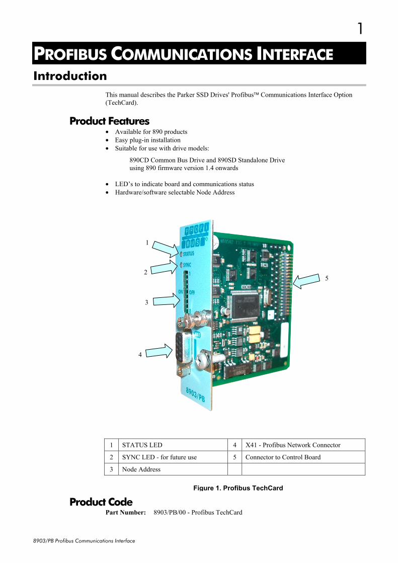
Product Features • Available for 890 products • Easy plug-in installation • Suitable for use with drive models:
890CD Common Bus Drive and 890SD Standalone Drive using 890 firmware version 1.4 onwards
• LED’s to indicate board and communications status • Hardware/software selectable Node Address
1 STATUS LED 4 X41 - Profibus Network Connector
2 SYNC LED - for future use 5 Connector to Control Board
3 Node Address
Product Code Part Number: 8903/PB/00 - Profibus TechCard
Figure 1. Profibus TechCard
1
5 2
3
4
2
8903/PB Profibus Communications Interface
1
1
3
2
2
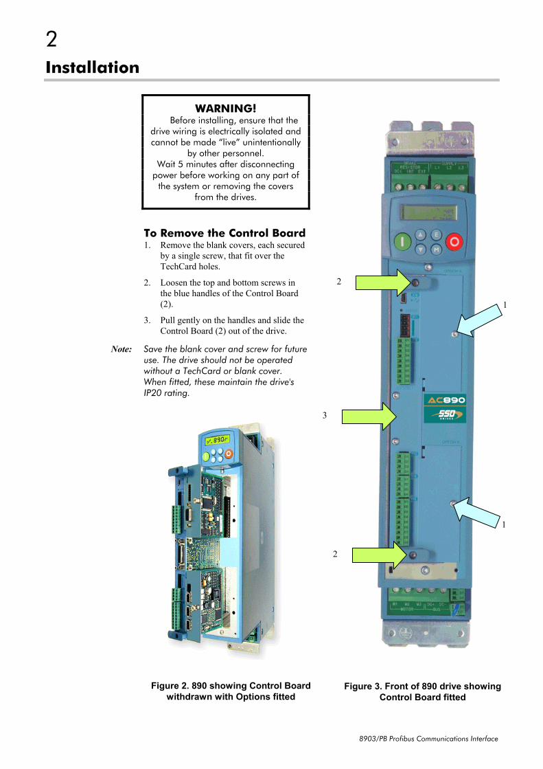
Installation
WARNING! Before installing, ensure that the
drive wiring is electrically isolated and cannot be made “live” unintentionally
by other personnel. Wait 5 minutes after disconnecting
power before working on any part of the system or removing the covers
from the drives.
To Remove the Control Board 1. Remove the blank covers, each secured
by a single screw, that fit over the TechCard holes.
2. Loosen the top and bottom screws in the blue handles of the Control Board (2).
3. Pull gently on the handles and slide the Control Board (2) out of the drive.
Note: Save the blank cover and screw for future use. The drive should not be operated without a TechCard or blank cover. When fitted, these maintain the drive's IP20 rating.
Figure 3. Front of 890 drive showing Control Board fitted
Figure 2. 890 showing Control Board withdrawn with Options fitted
3
8903/PB Profibus Communications Interface
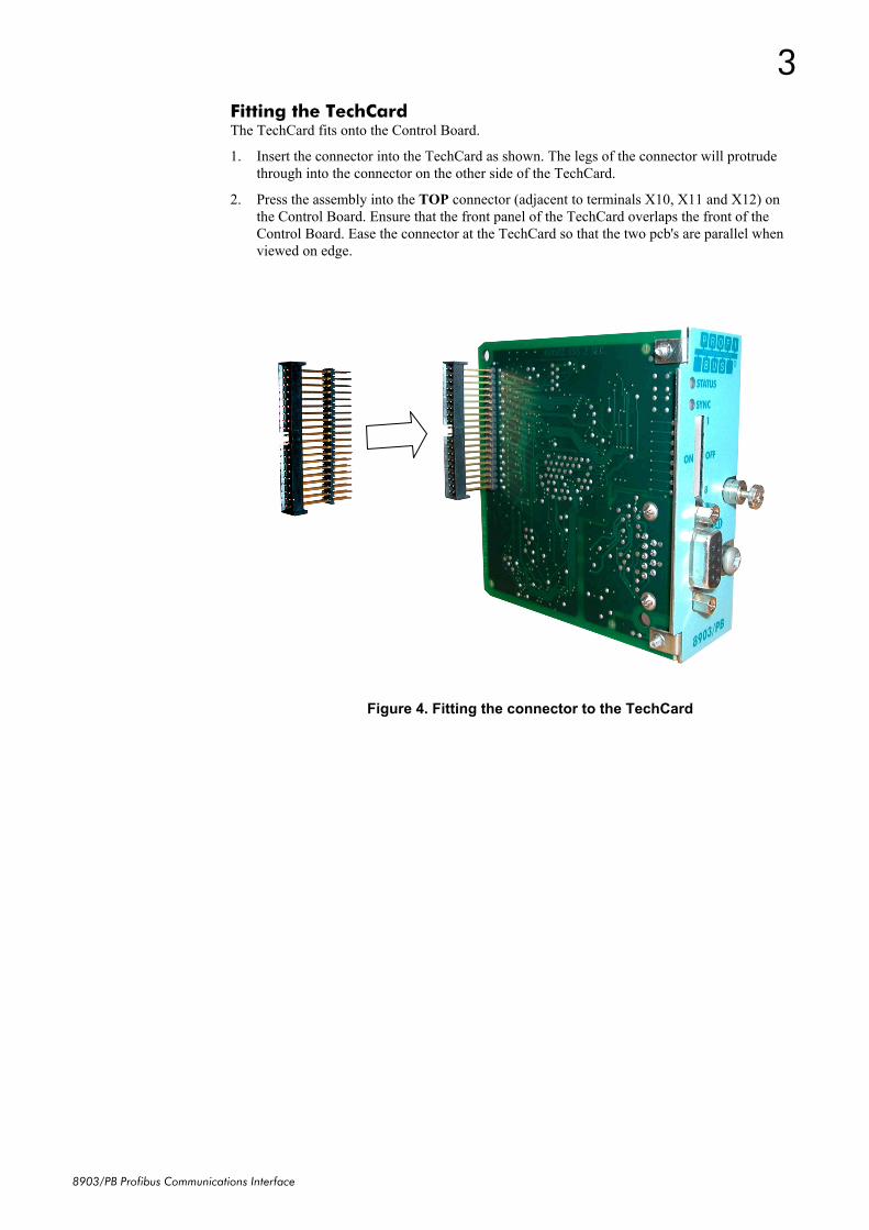
Fitting the TechCard The TechCard fits onto the Control Board.
1. Insert the connector into the TechCard as shown. The legs of the connector will protrude through into the connector on the other side of the TechCard.
2. Press the assembly into the TOP connector (adjacent to terminals X10, X11 and X12) on the Control Board. Ensure that the front panel of the TechCard overlaps the front of the Control Board. Ease the connector at the TechCard so that the two pcb's are parallel when viewed on edge.
Figure 4. Fitting the connector to the TechCard
4
8903/PB Profibus Communications Interface
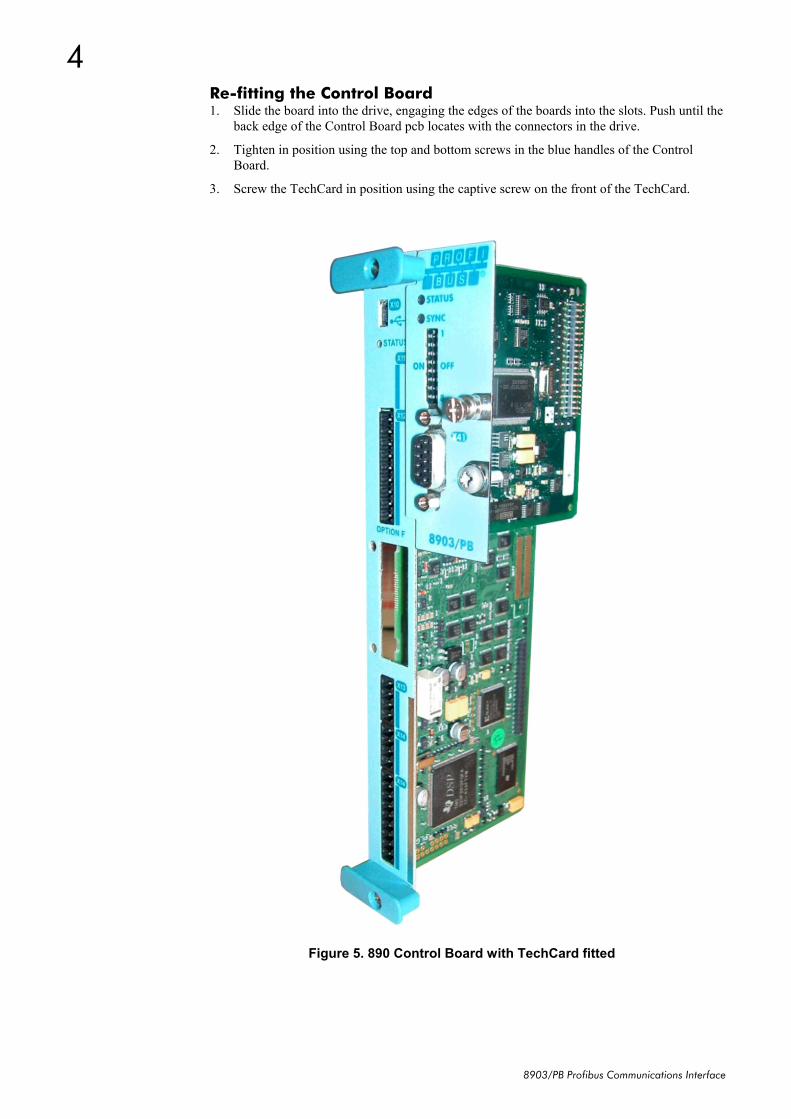
Re-fitting the Control Board 1. Slide the board into the drive, engaging the edges of the boards into the slots. Push until the
back edge of the Control Board pcb locates with the connectors in the drive.
2. Tighten in position using the top and bottom screws in the blue handles of the Control Board.
3. Screw the TechCard in position using the captive screw on the front of the TechCard.
Figure 5. 890 Control Board with TechCard fitted
5
8903/PB Profibus Communications Interface
Wiring the System
WARNING! Before installing, ensure that the drive and all wiring is electrically isolated and
cannot be made “live” unintentionally by other personnel.
Wait 5 minutes after disconnecting power before working on any part of the system or removing the covers from the Drive.
Note: It is possible to make serial communications operate without adhering to the following recommendations, however, the recommendations will promote greater reliability.
PROFIBUS-DP Cable Specification PROFIBUS-DP cable uses a specific colour code (red/green). You should maintain this colour code throughout your network. The cable has a single twisted pair with overall shielding.
The bus line is specified in IEC 61158 and it can be used in accordance with the table below.
Cable Parameters PROFIBUS line
Surge impedance in Ω 135 … 165
Capacitance per unit length (pF/m) < 30
Loop resistance (Ω/km) 110
Core diameter (mm) 0.64
Core cross-section (mm2) > 0.34
Note: Belden B3079E cable meets the above specification.
Maximum Line Length Per Bus Segment
Using the specified cable parameters, the maximum line length of a bus segment are as follows:
Transfer rate in kbit/s 9.6 31.25 45.45 93.75 187.5
Cable length 1200 1200 1200 1000 1000
Transfer rate in kbit/s 500 1500 3000 6000 12000
Cable length 400 200 100 100 100
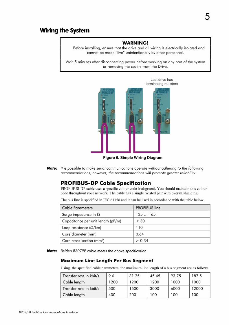
Figure 6. Simple Wiring Diagram
Last drive hasterminating resistors
6
8903/PB Profibus Communications Interface
PROFIBUS-DP Connectors You should use connectors recommended by Profibus. These connectors will have a shield clamp providing shield continuity and will help to ensure good noise immunity of your network.
We recommend the use of the horizontal Erbic range of PROFIBUS-DP connectors from ERNI:
♦ ERNI Part number 103648, grey - used on all nodes in the middle of the network
♦ ERNI Part number 103649, yellow - termination connector
♦ ERNI Part number 134728, grey - includes switchable termination
For further information, visit www.erni.com
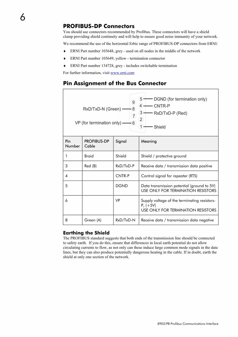
Pin Assignment of the Bus Connector
54321
9876
Shield
RxD/TxD-P (Red)CNTR-PDGND (for termination only)
RxD/TxD-N (Green)
VP (for termination only)
Pin Number
PROFIBUS-DP Cable
Signal Meaning
1 Braid Shield Shield / protective ground
3 Red (B) RxD/TxD-P Receive data / transmission data positive
4 CNTR-P Control signal for repeater (RTS)
5 DGND Data transmission potential (ground to 5V)USE ONLY FOR TERMINATION RESISTORS
6 VP Supply voltage of the terminating resistors-P, (+5V) USE ONLY FOR TERMINATION RESISTORS
8 Green (A) RxD/TxD-N Receive data / transmission data negative
Earthing the Shield The PROFIBUS standard suggests that both ends of the transmission line should be connected to safety earth. If you do this, ensure that differences in local earth potential do not allow circulating currents to flow, as not only can these induce large common mode signals in the data lines, but they can also produce potentially dangerous heating in the cable. If in doubt, earth the shield at only one section of the network.
7
8903/PB Profibus Communications Interface
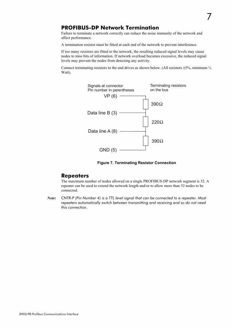
PROFIBUS-DP Network Termination Failure to terminate a network correctly can reduce the noise immunity of the network and affect performance.
A termination resistor must be fitted at each end of the network to prevent interference.
If too many resistors are fitted to the network, the resulting reduced signal levels may cause nodes to miss bits of information. If network overload becomes excessive, the reduced signal levels may prevent the nodes from detecting any activity.
Connect terminating resistors to the end drives as shown below. (All resistors ±5%, minimum ¼ Watt).
Data line B (3)
Data line A (8)
GND (5)
VP (6) 390 Ω
220 Ω
390 Ω
Terminating resistorson the bus
Signals at connectorPin number in parentheses
Repeaters The maximum number of nodes allowed on a single PROFIBUS-DP network segment is 32. A repeater can be used to extend the network length and/or to allow more than 32 nodes to be connected.
Note: CNTR-P (Pin Number 4) is a TTL level signal that can be connected to a repeater. Most repeaters automatically switch between transmitting and receiving and so do not need this connection.
Figure 7. Terminating Resistor Connection
8
8903/PB Profibus Communications Interface
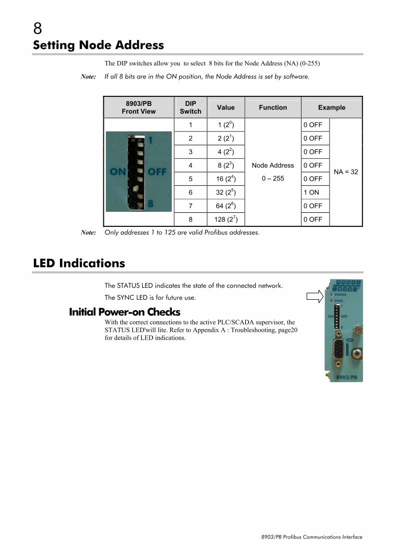
Setting Node Address The DIP switches allow you to select 8 bits for the Node Address (NA) (0-255)
Note: If all 8 bits are in the ON position, the Node Address is set by software.
8903/PB Front View
DIP Switch Value Function Example
1 1 (20) 0 OFF
2 2 (21) 0 OFF
3 4 (22) 0 OFF
4 8 (23) 0 OFF
5 16 (24) 0 OFF
6 32 (25) 1 ON
7 64 (26) 0 OFF
8 128 (27)
Node Address
0 – 255
0 OFF
NA = 32
Note: Only addresses 1 to 125 are valid Profibus addresses.
LED Indications
The STATUS LED indicates the state of the connected network.
The SYNC LED is for future use.
Initial Power-on Checks With the correct connections to the active PLC/SCADA supervisor, the STATUS LED'will lite. Refer to Appendix A : Troubleshooting, page20 for details of LED indications.
9
8903/PB Profibus Communications Interface
Drive Diagnostics
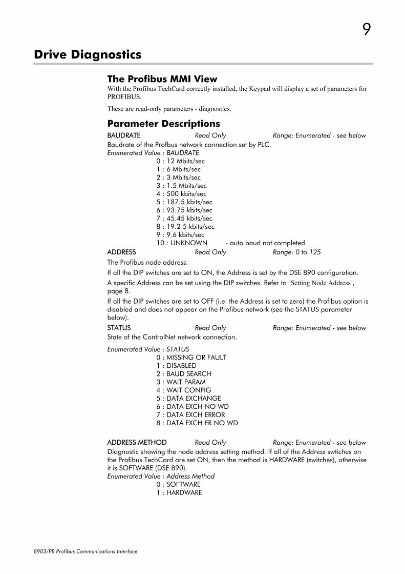
The Profibus MMI View With the Profibus TechCard correctly installed, the Keypad will display a set of parameters for PROFIBUS.
These are read-only parameters - diagnostics.
Parameter Descriptions BAUDRATE Read Only Range: Enumerated - see below Baudrate of the Profbus network connection set by PLC. Enumerated Value : BAUDRATE 0 : 12 Mbits/sec 1 : 6 Mbits/sec 2 : 3 Mbits/sec 3 : 1.5 Mbits/sec 4 : 500 kbits/sec 5 : 187.5 kbits/sec 6 : 93.75 kbits/sec 7 : 45.45 kbits/sec 8 : 19.2 5 kbits/sec 9 : 9.6 kbits/sec 10 : UNKNOWN - auto baud not completed ADDRESS Read Only Range: 0 to 125 The Profibus node address. If all the DIP switches are set to ON, the Address is set by the DSE 890 configuration. A specific Address can be set using the DIP switches. Refer to "Setting Node Address", page 8. If all the DIP switches are set to OFF (i.e. the Address is set to zero) the Profibus option is disabled and does not appear on the Profibus network (see the STATUS parameter below). STATUS Read Only Range: Enumerated - see below State of the ControlNet network connection.
Enumerated Value : STATUS 0 : MISSING OR FAULT 1 : DISABLED 2 : BAUD SEARCH 3 : WAIT PARAM 4 : WAIT CONFIG 5 : DATA EXCHANGE 6 : DATA EXCH NO WD 7 : DATA EXCH ERROR 8 : DATA EXCH ER NO WD ADDRESS METHOD Read Only Range: Enumerated - see below Diagnostic showing the node address setting method. If all of the Address swtiches on the Profibus TechCard are set ON, then the method is HARDWARE (switches), otherwise it is SOFTWARE (DSE 890). Enumerated Value : Address Method
0 : SOFTWARE 1 : HARDWARE
10
8903/PB Profibus Communications Interface
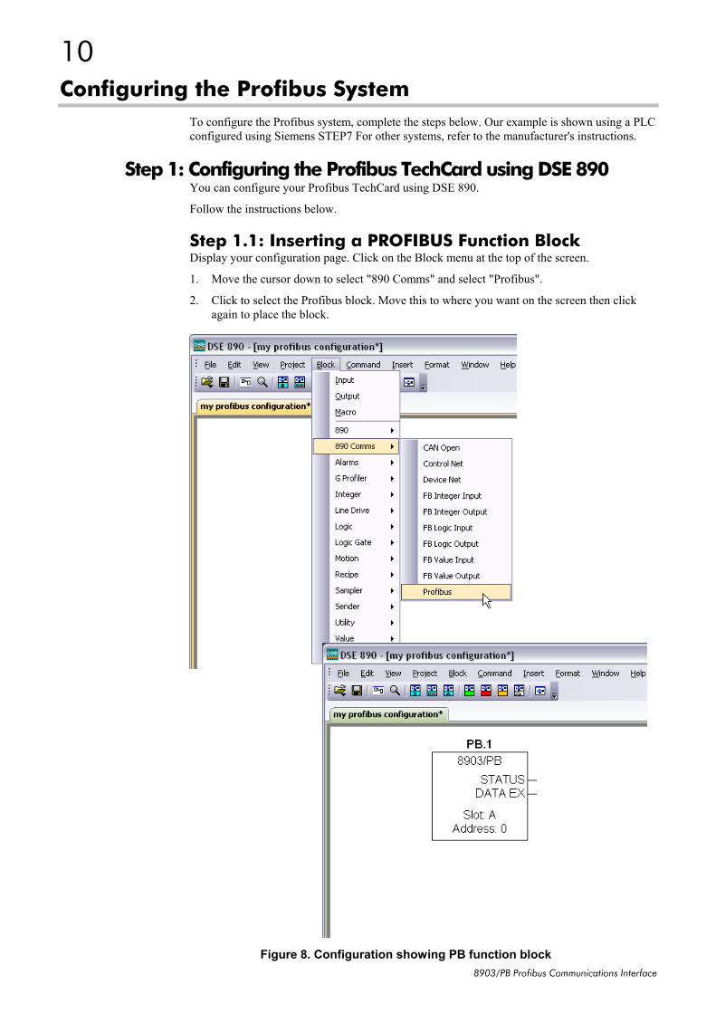
Configuring the Profibus System To configure the Profibus system, complete the steps below. Our example is shown using a PLC configured using Siemens STEP7 For other systems, refer to the manufacturer's instructions.
Step 1: Configuring the Profibus TechCard using DSE 890 You can configure your Profibus TechCard using DSE 890.
Follow the instructions below.
Step 1.1: Inserting a PROFIBUS Function Block Display your configuration page. Click on the Block menu at the top of the screen.
1. Move the cursor down to select "890 Comms" and select "Profibus".
2. Click to select the Profibus block. Move this to where you want on the screen then click again to place the block.
Figure 8. Configuration showing PB function block
11
8903/PB Profibus Communications Interface
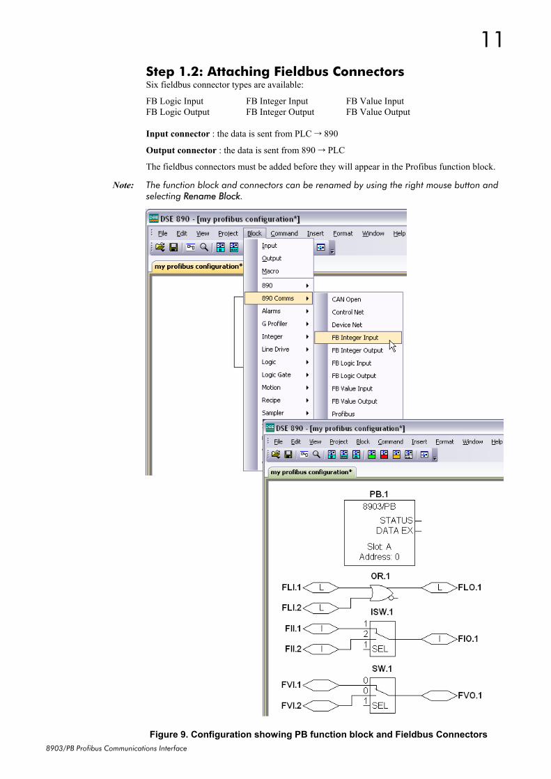
Step 1.2: Attaching Fieldbus Connectors Six fieldbus connector types are available:
FB Logic Input FB Integer Input FB Value Input FB Logic Output FB Integer Output FB Value Output Input connector : the data is sent from PLC 890
Output connector : the data is sent from 890 PLC
The fieldbus connectors must be added before they will appear in the Profibus function block.
Note: The function block and connectors can be renamed by using the right mouse button and selecting Rename Block.
Figure 9. Configuration showing PB function block and Fieldbus Connectors
12
8903/PB Profibus Communications Interface
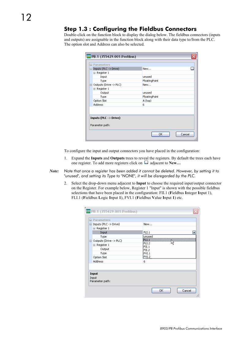
Step 1.3 : Configuring the Fieldbus Connectors Double-click on the function block to display the dialog below. The fieldbus connectors (inputs and outputs) are assignable in the function block along with their data type to/from the PLC. The option slot and Address can also be selected.
To configure the input and output connectors you have placed in the configuration:
1. Expand the Inputs and Outputs trees to reveal the registers. By default the trees each have one register. To add more registers click on adjacent to New…
Note: Note that once a register has been added it cannot be deleted. However, by setting it to "unused", and setting its Type to "NONE", it will be disregarded by the PLC.
2. Select the drop-down menu adjacent to Input to choose the required input/output connector on the Register. For example below, Register 1 "Input" is shown with the possible fieldbus selections that have been placed in the configuration: FII.1 (Fieldbus Integer Input 1), FLI.1 (Fieldbus Logic Input 1), FVI.1 (Fieldbus Value Input 1) etc.
13
8903/PB Profibus Communications Interface
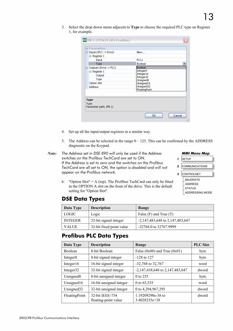
3. Select the drop down menu adjacent to Type to choose the required PLC type on Register 1, for example.
4. Set up all the input/output registers in a similar way.
5. The Address can be selected in the range 0 – 125. This can be confirmed by the ADDRESS diagnostic on the Keypad.
Note: The Address set in DSE 890 will only be used if the Address switches on the Profibus TechCard are set to ON. If the Address is set to zero and the switches on the Profibus TechCard are all set to ON, the option is disabled and will not appear on the Profibus network.
6. "Option Slot" = A (top). The Profibus TechCard can only be fitted in the OPTION A slot on the front of the drive. This is the default setting for "Option Slot".
DSE Data Types
Data Type Description Range LOGIC Logic False (F) and True (T) INTEGER 32-bit signed integer -2,147,483,648 to 2,147,483,647 VALUE 32-bit fixed point value -32768.0 to 32767.9999
Profibus PLC Data Types
Data Type Description Range PLC Size Boolean 8-bit Boolean False (0x00) and True (0x01) byte Integer8 8-bit signed integer -128 to 127 byte Integer16 16-bit signed integer -32,768 to 32,767 word Integer32 32-bit signed integer -2,147,438,648 to 2,147,483,647 dword Unsigned8 8-bit unsigned integer 0 to 255 byte Unsigned16 16-bit unsigned integer 0 to 65,535 word Unsigned32 32-bit unsigned integer 0 to 4,294,967,295 dword FloatingPoint 32-bit IEEE-754
floating-point value 1.19209290e-38 to 3.4028235e+38
dword
MMI Menu Map
1 SETUP
2 COMMUNICATIONS
3 CONTROLNET
BAUDRATE
ADDRESS
STATUS
ADDRESSING MODE
14
8903/PB Profibus Communications Interface
Conversion of DSE Type < > Profibus Type The DSE fieldbus connectors are each assigned a Profibus PLC "Type" as described in "Step 1.3 : Configuring the Fieldbus Connectors" on page 12.
The conversion between the DSE type and the PLC type is performed automatically (refer to Appendix B : DSE/Profibus Conversion Rules, page 21).
Any PLC type can be assigned to a fieldbus connector
Some recommended PLC type assignments to fieldbus connectors are given in the table below:
Fieldbus Connector PLC Type PLC Size LOGIC Boolean byte INTEGER Integer32 dword VALUE FloatingPoint dword
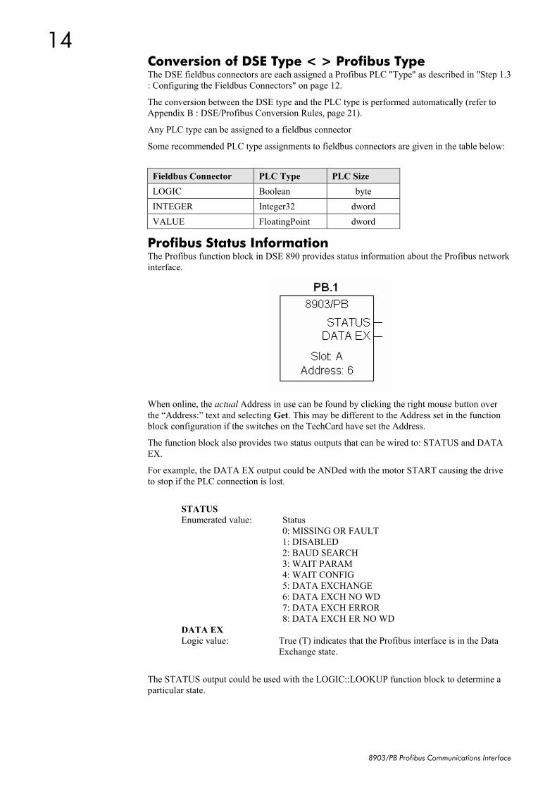
Profibus Status Information The Profibus function block in DSE 890 provides status information about the Profibus network interface.
When online, the actual Address in use can be found by clicking the right mouse button over the “Address:” text and selecting Get. This may be different to the Address set in the function block configuration if the switches on the TechCard have set the Address.
The function block also provides two status outputs that can be wired to: STATUS and DATA EX.
For example, the DATA EX output could be ANDed with the motor START causing the drive to stop if the PLC connection is lost.
STATUS Enumerated value: Status 0: MISSING OR FAULT 1: DISABLED 2: BAUD SEARCH 3: WAIT PARAM 4: WAIT CONFIG 5: DATA EXCHANGE 6: DATA EXCH NO WD 7: DATA EXCH ERROR 8: DATA EXCH ER NO WD DATA EX Logic value: True (T) indicates that the Profibus interface is in the Data
Exchange state.
The STATUS output could be used with the LOGIC::LOOKUP function block to determine a particular state.
15
8903/PB Profibus Communications Interface
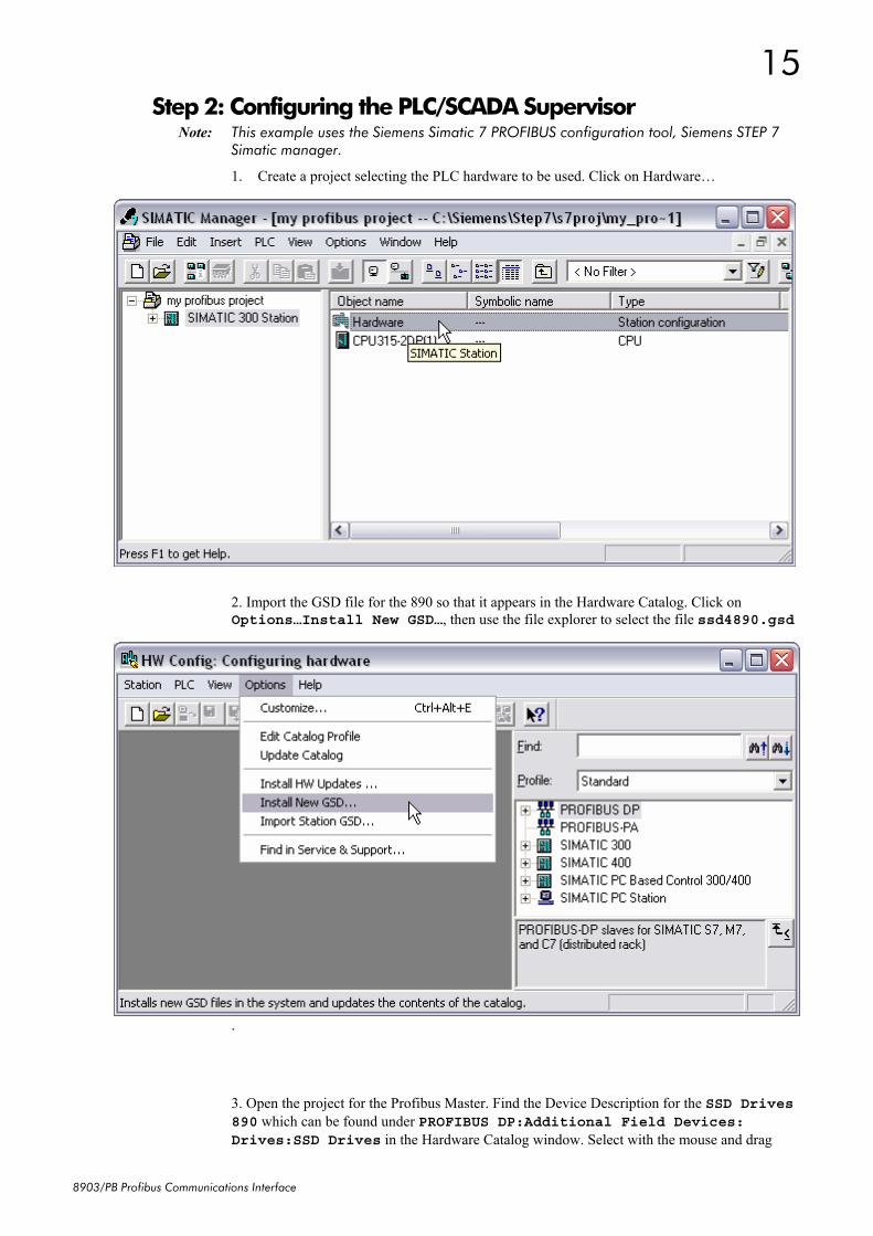
Step 2: Configuring the PLC/SCADA Supervisor Note: This example uses the Siemens Simatic 7 PROFIBUS configuration tool, Siemens STEP 7
Simatic manager.
1. Create a project selecting the PLC hardware to be used. Click on Hardware…
2. Import the GSD file for the 890 so that it appears in the Hardware Catalog. Click on Options…Install New GSD…, then use the file explorer to select the file ssd4890.gsd
.
3. Open the project for the Profibus Master. Find the Device Description for the SSD Drives 890 which can be found under PROFIBUS DP:Additional Field Devices: Drives:SSD Drives in the Hardware Catalog window. Select with the mouse and drag
16
8903/PB Profibus Communications Interface
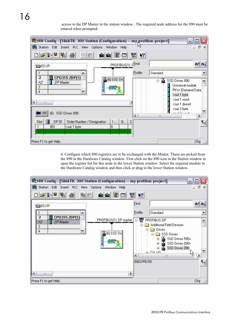
across to the DP Master in the station window.. The required node address for the 890 must be entered when prompted.
4. Configure which 890 registers are to be exchanged with the Master. These are picked from the 890 in the Hardware Catalog window. First click on the 890 icon in the Station window to open the register list for this node in the lower Station window. Select the required module in the Hardware Catalog window and then click or drag to the lower Station window.
17
8903/PB Profibus Communications Interface
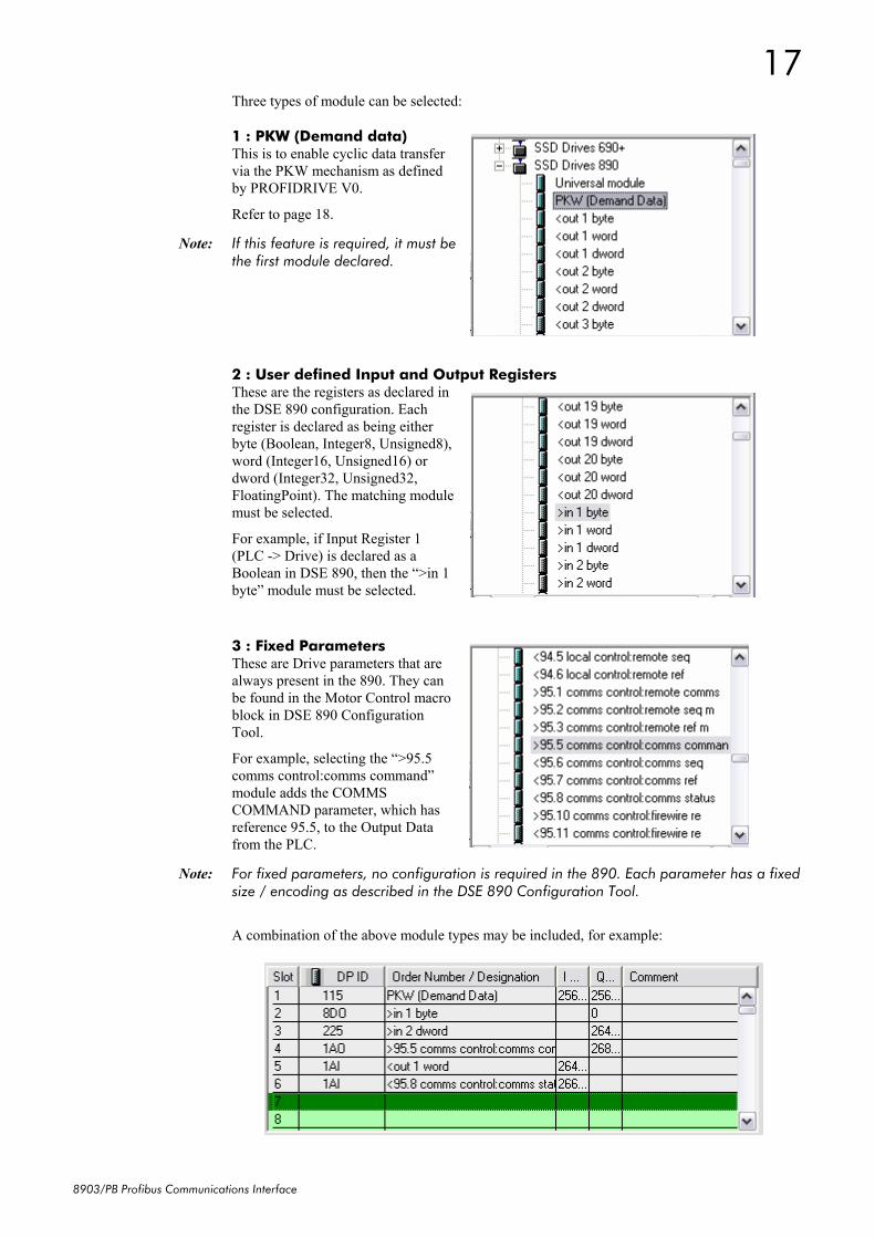
Three types of module can be selected:
1 : PKW (Demand data) This is to enable cyclic data transfer via the PKW mechanism as defined by PROFIDRIVE V0.
Refer to page 18.
Note: If this feature is required, it must be the first module declared.
2 : User defined Input and Output Registers These are the registers as declared in the DSE 890 configuration. Each register is declared as being either byte (Boolean, Integer8, Unsigned8), word (Integer16, Unsigned16) or dword (Integer32, Unsigned32, FloatingPoint). The matching module must be selected.
For example, if Input Register 1 (PLC -> Drive) is declared as a Boolean in DSE 890, then the “>in 1 byte” module must be selected.
3 : Fixed Parameters These are Drive parameters that are always present in the 890. They can be found in the Motor Control macro block in DSE 890 Configuration Tool.
For example, selecting the “>95.5 comms control:comms command” module adds the COMMS COMMAND parameter, which has reference 95.5, to the Output Data from the PLC.
Note: For fixed parameters, no configuration is required in the 890. Each parameter has a fixed size / encoding as described in the DSE 890 Configuration Tool.
A combination of the above module types may be included, for example:
18
8903/PB Profibus Communications Interface
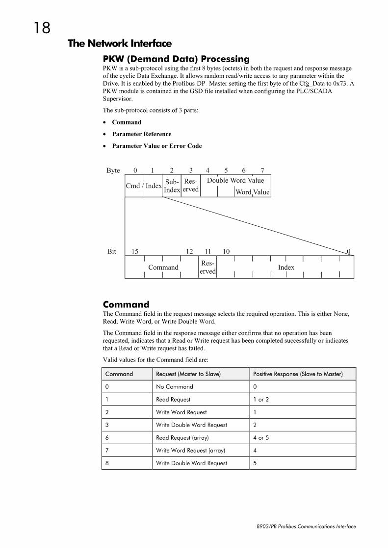
The Network Interface PKW (Demand Data) Processing PKW is a sub-protocol using the first 8 bytes (octets) in both the request and response message of the cyclic Data Exchange. It allows random read/write access to any parameter within the Drive. It is enabled by the Profibus-DP- Master setting the first byte of the Cfg_Data to 0x73. A PKW module is contained in the GSD file installed when configuring the PLC/SCADA Supervisor.
The sub-protocol consists of 3 parts:
• Command
• Parameter Reference
• Parameter Value or Error Code
Byte 0 1 2 3 4 5 6 7 Res-erved Cmd / Index
Word Value
011 12 15 Bit
Command Index
10
Sub-Index
Res-erved
Double Word Value
Command The Command field in the request message selects the required operation. This is either None, Read, Write Word, or Write Double Word.
The Command field in the response message either confirms that no operation has been requested, indicates that a Read or Write request has been completed successfully or indicates that a Read or Write request has failed.
Valid values for the Command field are:
Command Request (Master to Slave) Positive Response (Slave to Master)
0 No Command 0
1 Read Request 1 or 2
2 Write Word Request 1
3 Write Double Word Request 2
6 Read Request (array) 4 or 5
7 Write Word Request (array) 4
8 Write Double Word Request 5
19
8903/PB Profibus Communications Interface
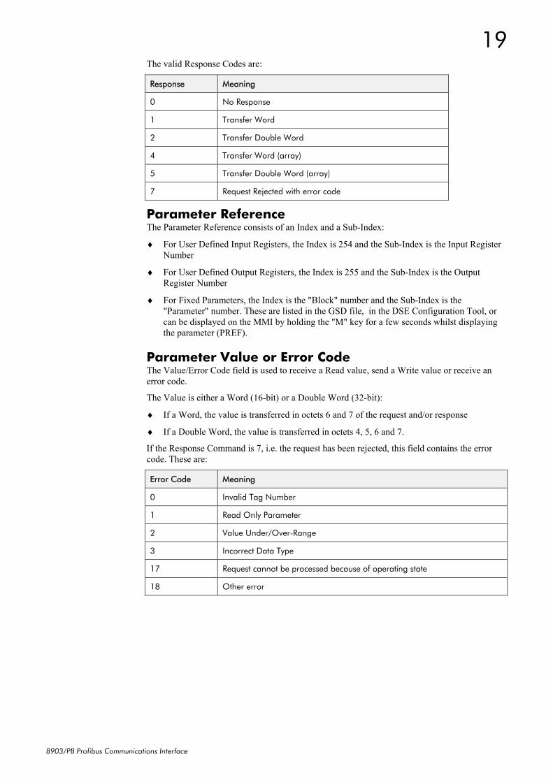
The valid Response Codes are:
Response Meaning
0 No Response
1 Transfer Word
2 Transfer Double Word
4 Transfer Word (array)
5 Transfer Double Word (array)
7 Request Rejected with error code
Parameter Reference The Parameter Reference consists of an Index and a Sub-Index:
♦ For User Defined Input Registers, the Index is 254 and the Sub-Index is the Input Register Number
♦ For User Defined Output Registers, the Index is 255 and the Sub-Index is the Output Register Number
♦ For Fixed Parameters, the Index is the "Block" number and the Sub-Index is the "Parameter" number. These are listed in the GSD file, in the DSE Configuration Tool, or can be displayed on the MMI by holding the "M" key for a few seconds whilst displaying the parameter (PREF).
Parameter Value or Error Code The Value/Error Code field is used to receive a Read value, send a Write value or receive an error code.
The Value is either a Word (16-bit) or a Double Word (32-bit):
♦ If a Word, the value is transferred in octets 6 and 7 of the request and/or response
♦ If a Double Word, the value is transferred in octets 4, 5, 6 and 7.
If the Response Command is 7, i.e. the request has been rejected, this field contains the error code. These are:
Error Code Meaning
0 Invalid Tag Number
1 Read Only Parameter
2 Value Under/Over-Range
3 Incorrect Data Type
17 Request cannot be processed because of operating state
18 Other error
20
8903/PB Profibus Communications Interface
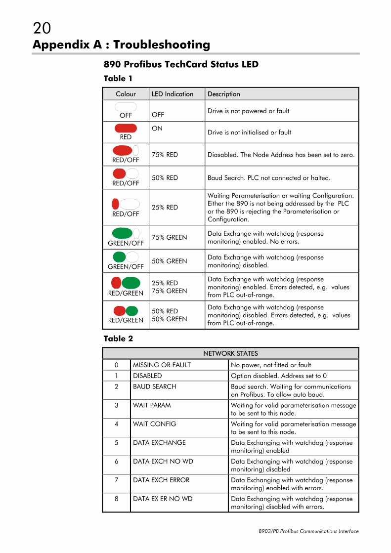
Appendix A : Troubleshooting
890 Profibus TechCard Status LED Table 1
Colour LED Indication Description
OFF
OFF Drive is not powered or fault
RED
ON Drive is not initialised or fault
RED/OFF
75% RED Diasabled. The Node Address has been set to zero.
RED/OFF
50% RED Baud Search. PLC not connected or halted.
RED/OFF
25% RED
Waiting Parameterisation or waiting Configuration. Either the 890 is not being addressed by the PLC or the 890 is rejecting the Parameterisation or Configuration.
GREEN/OFF
75% GREEN Data Exchange with watchdog (response monitoring) enabled. No errors.
GREEN/OFF
50% GREEN Data Exchange with watchdog (response monitoring) disabled.
RED/GREEN
25% RED 75% GREEN
Data Exchange with watchdog (response monitoring) enabled. Errors detected, e.g. values from PLC out-of-range.
RED/GREEN
50% RED 50% GREEN
Data Exchange with watchdog (response monitoring) disabled. Errors detected, e.g. values from PLC out-of-range.
Table 2
NETWORK STATES
0 MISSING OR FAULT No power, not fitted or fault
1 DISABLED Option disabled. Address set to 0
2 BAUD SEARCH Baud search. Waiting for communications on Profibus. To allow auto baud.
3 WAIT PARAM Waiting for valid parameterisation message to be sent to this node.
4 WAIT CONFIG Waiting for valid parameterisation message to be sent to this node.
5 DATA EXCHANGE Data Exchanging with watchdog (response monitoring) enabled
6 DATA EXCH NO WD Data Exchanging with watchdog (response monitoring) disabled
7 DATA EXCH ERROR Data Exchanging with watchdog (response monitoring) enabled with errors.
8 DATA EX ER NO WD Data Exchanging with watchdog (response monitoring) disabled with errors.
21
8903/PB Profibus Communications Interface
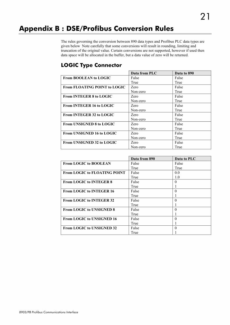
Appendix B : DSE/Profibus Conversion Rules
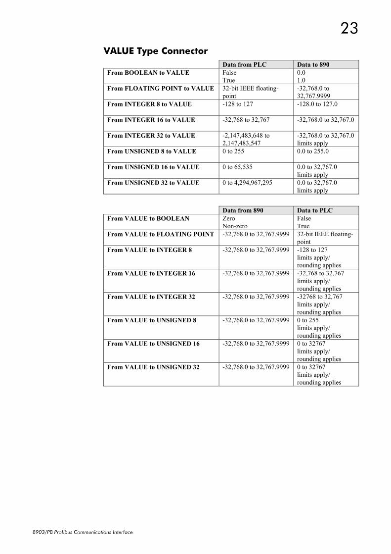
The rules governing the conversion between 890 data types and Profibus PLC data types are given below Note carefully that some conversions will result in rounding, limiting and truncation of the original value. Certain conversions are not supported, however if used then data space will be allocated in the buffer, but a data value of zero will be returned.
LOGIC Type Connector Data from PLC Data to 890 From BOOLEAN to LOGIC False
True False True
From FLOATING POINT to LOGIC Zero Non-zero
False True
From INTEGER 8 to LOGIC Zero Non-zero
False True
From INTEGER 16 to LOGIC Zero Non-zero
False True
From INTEGER 32 to LOGIC Zero Non-zero
False True
From UNSIGNED 8 to LOGIC Zero Non-zero
False True
From UNSIGNED 16 to LOGIC Zero Non-zero
False True
From UNSIGNED 32 to LOGIC Zero Non-zero
False True
Data from 890 Data to PLC From LOGIC to BOOLEAN False
True False True
From LOGIC to FLOATING POINT False True
0.0 1.0
From LOGIC to INTEGER 8 False True
0 1
From LOGIC to INTEGER 16 False True
0 1
From LOGIC to INTEGER 32 False True
0 1
From LOGIC to UNSIGNED 8 False True
0 1
From LOGIC to UNSIGNED 16 False True
0 1
From LOGIC to UNSIGNED 32 False True
0 1
22
8903/PB Profibus Communications Interface
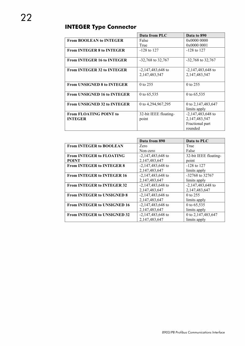
INTEGER Type Connector Data from PLC Data to 890 From BOOLEAN to INTEGER False
True 0x0000 0000 0x0000 0001
From INTEGER 8 to INTEGER -128 to 127
-128 to 127
From INTEGER 16 to INTEGER -32,768 to 32,767
-32,768 to 32,767
From INTEGER 32 to INTEGER -2,147,483,648 to 2,147,483,547
-2,147,483,648 to 2,147,483,547
From UNSIGNED 8 to INTEGER 0 to 255
0 to 255
From UNSIGNED 16 to INTEGER 0 to 65,535
0 to 65,535
From UNSIGNED 32 to INTEGER 0 to 4,294,967,295
0 to 2,147,483,647 limits apply
From FLOATING POINT to INTEGER
32-bit IEEE floating-point
-2,147,483,648 to 2,147,483,547 Fractional part rounded
Data from 890 Data to PLC From INTEGER to BOOLEAN Zero
Non-zero True False
From INTEGER to FLOATING POINT
-2,147,483,648 to 2,147,483,647
32-bit IEEE floating-point
From INTEGER to INTEGER 8 -2,147,483,648 to 2,147,483,647
-128 to 127 limits apply
From INTEGER to INTEGER 16 -2,147,483,648 to 2,147,483,647
-32768 to 32767 limits apply
From INTEGER to INTEGER 32 -2,147,483,648 to 2,147,483,647
-2,147,483,648 to 2,147,483,647
From INTEGER to UNSIGNED 8 -2,147,483,648 to 2,147,483,647
0 to 255 limits apply
From INTEGER to UNSIGNED 16 -2,147,483,648 to 2,147,483,647
0 to 65,535 limits apply
From INTEGER to UNSIGNED 32 -2,147,483,648 to 2,147,483,647
0 to 2,147,483,647 limits apply
23
8903/PB Profibus Communications Interface
VALUE Type Connector Data from PLC Data to 890 From BOOLEAN to VALUE False
True 0.0 1.0
From FLOATING POINT to VALUE 32-bit IEEE floating-point
-32,768.0 to 32,767.9999
From INTEGER 8 to VALUE -128 to 127
-128.0 to 127.0
From INTEGER 16 to VALUE -32,768 to 32,767
-32,768.0 to 32,767.0
From INTEGER 32 to VALUE -2,147,483,648 to 2,147,483,547
-32,768.0 to 32,767.0 limits apply
From UNSIGNED 8 to VALUE 0 to 255
0.0 to 255.0
From UNSIGNED 16 to VALUE 0 to 65,535
0.0 to 32,767.0 limits apply
From UNSIGNED 32 to VALUE 0 to 4,294,967,295
0.0 to 32,767.0 limits apply
Data from 890 Data to PLC From VALUE to BOOLEAN Zero
Non-zero False True
From VALUE to FLOATING POINT -32,768.0 to 32,767.9999
32-bit IEEE floating-point
From VALUE to INTEGER 8 -32,768.0 to 32,767.9999
-128 to 127 limits apply/ rounding applies
From VALUE to INTEGER 16 -32,768.0 to 32,767.9999
-32,768 to 32,767 limits apply/ rounding applies
From VALUE to INTEGER 32 -32,768.0 to 32,767.9999
-32768 to 32,767 limits apply/ rounding applies
From VALUE to UNSIGNED 8 -32,768.0 to 32,767.9999
0 to 255 limits apply/ rounding applies
From VALUE to UNSIGNED 16 -32,768.0 to 32,767.9999
0 to 32767 limits apply/ rounding applies
From VALUE to UNSIGNED 32 -32,768.0 to 32,767.9999
0 to 32767 limits apply/ rounding applies
24
8903/PB Profibus Communications Interface
ISS. MODIFICATION ECN No. DATE DRAWN CHK'D
1 Initial Issue (HA469267U001) 17320 03/06/05 CM KJ
2 Various small amendments 19213 15/02/06 CM KJ
3 Company name change. 19591 26/04/07 CM KJ
FIRST USED ON MODIFICATION RECORD
8903/PB Profibus Communications Interface
DRAWING NUMBER
ZZ469267C001
SHT. 1
OF 1