9001-0004 - hyd test fixture - technical reference manual · assembly cooling shroud ... this time...
TRANSCRIPT

_______________________________________________________
Technical Reference Manual
Document# 9001-0004
Hydraulic Test Fixture
Project: 102K15
Released: November 3, 2005
Revised: February 22, 2006 Added production test procedure
________________________________________________________
Hydraulic Test Fixture
Project# 102K15
Document# 9001-0004
Revised: 2/22/2006
Page 2 of 15
Notice: This report is proprietary to Air Tractor. It is provided to our customer with the understanding that each recipient agrees to disclose any information contained within it to only those persons in its organization having a “need to know”.
Table Of Contents
Production Test Procedure ...........................................................................................3 Connections required for an FRDS system...................................................................3
Production Test Sequence / Parameters........................................................................4
Production Operator Test Instructions..........................................................................4
System Overview ...........................................................................................................6 Operation Overview ....................................................................................................6
Hardware Overview.....................................................................................................7
Connections...............................................................................................................10
Temperature Control & Sensors ................................................................................11 Temperature Control .................................................................................................11
Temperature Error .....................................................................................................11
Manual Valve On / Run Pump-Start Switch..............................................................12
Hydraulic Valve ........................................................................................................12
Run Pump-Start Switch .............................................................................................12
Pressure Sensor ...........................................................................................................12
Run Mode Switch ........................................................................................................13
Cycle Descriptions .......................................................................................................14
Power / Cycle In Progress Light .................................................................................14
Input / Output Usage...................................................................................................15

Hydraulic Test Fixture
Project# 102K15
Document# 9001-0004
Revised: 2/22/2006
Page 3 of 15
Notice: This report is proprietary to Air Tractor. It is provided to our customer with the understanding that each recipient agrees to disclose any information contained within it to only those persons in its organization having a “need to know”.
Production Test Procedure The test fixture controller has been designed so that it can be used with an existing FRDS
unit (production test stand) or as part of a stand alone system shown later. The following
sections outline the operation of the system as well as the operator actions required.
Please read the remainder of this document to fully understand the test fixture’s design
intent and capabilities.
Note that a custom reservoir has been built that includes temperature sensors and a heater
element to control the temperature of the oil. This reservoir must be used in conjunction
with the test fixture controller for the oil temperature to be controlled and monitored.
Figure 1 ~ Pump test fixture controller front panel
Connections required for an FRDS system
1. Assembly cooling shroud and cooling blower to pump shroud assembly
2. Make the following electrical connections
Hydraulic Test Fixture
Project# 102K15
Document# 9001-0004
Revised: 2/22/2006
Page 4 of 15
Notice: This report is proprietary to Air Tractor. It is provided to our customer with the understanding that each recipient agrees to disclose any information contained within it to only those persons in its organization having a “need to know”.
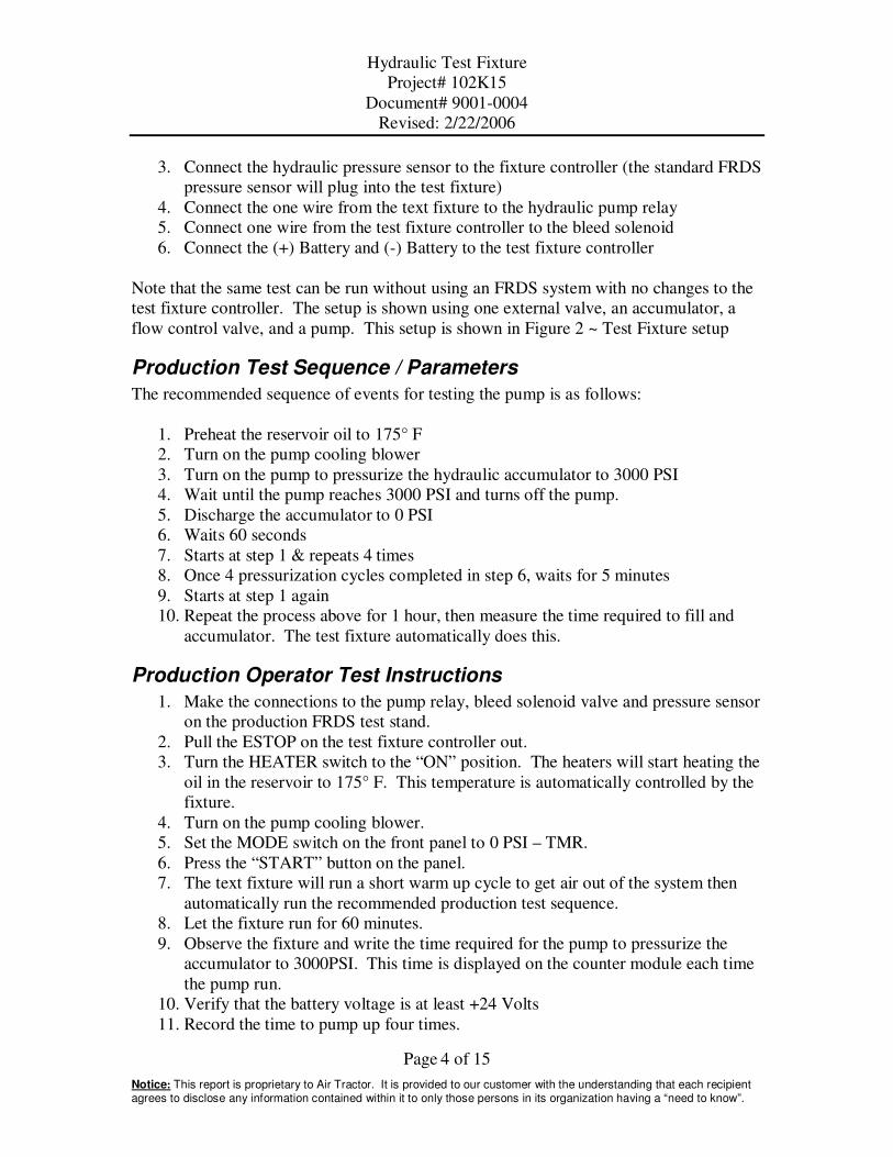
3. Connect the hydraulic pressure sensor to the fixture controller (the standard FRDS
pressure sensor will plug into the test fixture)
4. Connect the one wire from the text fixture to the hydraulic pump relay
5. Connect one wire from the test fixture controller to the bleed solenoid
6. Connect the (+) Battery and (-) Battery to the test fixture controller
Note that the same test can be run without using an FRDS system with no changes to the
test fixture controller. The setup is shown using one external valve, an accumulator, a
flow control valve, and a pump. This setup is shown in Figure 2 ~ Test Fixture setup
Production Test Sequence / Parameters
The recommended sequence of events for testing the pump is as follows:
1. Preheat the reservoir oil to 175° F
2. Turn on the pump cooling blower
3. Turn on the pump to pressurize the hydraulic accumulator to 3000 PSI
4. Wait until the pump reaches 3000 PSI and turns off the pump.
5. Discharge the accumulator to 0 PSI
6. Waits 60 seconds
7. Starts at step 1 & repeats 4 times
8. Once 4 pressurization cycles completed in step 6, waits for 5 minutes
9. Starts at step 1 again
10. Repeat the process above for 1 hour, then measure the time required to fill and
accumulator. The test fixture automatically does this.
Production Operator Test Instructions
1. Make the connections to the pump relay, bleed solenoid valve and pressure sensor
on the production FRDS test stand.
2. Pull the ESTOP on the test fixture controller out.
3. Turn the HEATER switch to the “ON” position. The heaters will start heating the
oil in the reservoir to 175° F. This temperature is automatically controlled by the
fixture.
4. Turn on the pump cooling blower.
5. Set the MODE switch on the front panel to 0 PSI – TMR.
6. Press the “START” button on the panel.
7. The text fixture will run a short warm up cycle to get air out of the system then
automatically run the recommended production test sequence.
8. Let the fixture run for 60 minutes.
9. Observe the fixture and write the time required for the pump to pressurize the
accumulator to 3000PSI. This time is displayed on the counter module each time
the pump run.
10. Verify that the battery voltage is at least +24 Volts
11. Record the time to pump up four times.

Hydraulic Test Fixture
Project# 102K15
Document# 9001-0004
Revised: 2/22/2006
Page 5 of 15
Notice: This report is proprietary to Air Tractor. It is provided to our customer with the understanding that each recipient agrees to disclose any information contained within it to only those persons in its organization having a “need to know”.
12. If the longest time to pressurize is greater than 45 seconds, the pump is bad.
Check battery voltage and verify that the pump cooling blower is operating
correctly. Retest the pump if necessary.
13. Stop the test fixture by turning the MODE switch to the “OFF” position.
Depressing the ESTOP button will also remove power from the entire system.
Note: If the pump fails to pressurize the system to 3000PSI within one minute during the
test sequence, the fixture will automatically shut down and the POWER/IN CYCLE lamp
will go off & flash once every 5 seconds. The pump should be retested with an operator
present if this happens. In general this indicates that the pump is bad, cooling is
insufficient or the battery is low.

Hydraulic Test Fixture
Project# 102K15
Document# 9001-0004
Revised: 2/22/2006
Page 6 of 15
Notice: This report is proprietary to Air Tractor. It is provided to our customer with the understanding that each recipient agrees to disclose any information contained within it to only those persons in its organization having a “need to know”.
System Overview
A test fixture has been developed to test & qualify production hydraulic pumps before
shipment on an FRDS system. The goals of the fixture are as follows:
� Control oil reservoir temperature to within 10 degrees F.
� Test the pumps performance at elevated temperature before shipment.
� Perform cycle testing on pumps if desired.
� Provide the operator with the time required to pressurize a hydraulic accumulator
to 3000 PSI (if in one of the Timer modes).
� Provide the operator with the total number of charge/discharge cycles made by the
pump (if in on of the counter modes).
While the test fixture does not measure actual pump flow, it effectively provides a
qualitative measure of the pumps performance. The time required to charge a hydraulic
accumulator is used to determine if the pump is operating satisfactorily. Time to
pressurize the accumulator is directly correlated to the pumps flow characteristics across
the entire pressure range we are interested in so this is a valid test method.
Operation Overview
The test fixture performs the basic functions outlined below:
� Controls the oil temperature to within +5 degrees F
� Displays time & count information to the operator
� Controls a pump and valve to achieve the following sequence of events
1. Turns on the pump to pressurize the hydraulic accumulator to 3000 PSI
2. Turns off the pump when the pressure reaches 3000 PSI
3. Discharges the accumulator to either 0 PSI or 2200 PSI depending on mode
selected
4. Waits for a specified amount of time (60 seconds)
5. Starts at step 1 & repeats 4 times
6. Once 4 pressurization cycles completed, waits for 5 minutes
7. Starts at step 1 again
The sequence of events for the test fixture is shown in the following sections. Note that
the temperature controls and valve on/run pump switch can be viewed as independent
processes.

Hydraulic Test Fixture
Project# 102K15
Document# 9001-0004
Revised: 2/22/2006
Page 7 of 15
Notice: This report is proprietary to Air Tractor. It is provided to our customer with the understanding that each recipient agrees to disclose any information contained within it to only those persons in its organization having a “need to know”.
Hardware Overview
The test fixture is comprised of the basic components outlined below:
� Programmable Logic Controller – Used to sequence the test
� Counter Module – Used to display pressurization time or cycle count to operator
� Amp meter – Used to display the amperage consumption or voltage to the pump
motor
� Switches & Light – Used to allow the operator to control fixture actions
� Hydraulic Reservoir – Oil for system testing is stored
� Heating Element – Heating element embedded into reservoir to heat the oil up to
the specified temperature
� Variac – Used to limit the maximum amount of energy that is available to drive
the heating element. This is not required but was used to avoid local boiling of oil
around the heating element. Set this to 80%.
� Temperature Gage – Embedded into the hydraulic reservoir to display the oil
temperature to an operator.
� Setpoint Temperature Sensor – Sensor embedded into the hydraulic reservoir that
switches once the desired oil temperature has been reached. The PLC monitors
this sensor and controls the heater based on this sensors state (on or off)
� Alarm Temperature Sensor - Sensor embedded into the hydraulic reservoir that
switches once the maximum allowable oil temperature has been reached. The
PLC monitors this sensor and can shut the test down and the heater off based on
this sensors state (on or off).
� Hydraulic Relay – Used to turn the pump on and off.
� Hydraulic Pump – Used to pressurize the system and is the device under test
(DUT).
� High Pressure filter – Filter used to remove oil contaminants.
� Hydraulic accumulator – One gallon accumulator that is pressurized by the pump
during the test. The pre-charge on this accumulator must be set to 1650 PSI for
test results to be valid.
� Pressure Sensor – Used to measure system hydraulic pressure. The PLC uses this
sensors input to control the pump.
� Hydraulic Valve – Used to dump pressure from the accumulator back to the
reservoir once the pump has pressurized the accumulator.
� Flow Control Valve – Used to limit the oil flow from the hydraulic valve when
dumping accumulator pressure back to the tank.
The test fixture is shown in the figures below:

Hydraulic Test Fixture
Project# 102K15
Document# 9001-0004
Revised: 2/22/2006
Page 8 of 15
Notice: This report is proprietary to Air Tractor. It is provided to our customer with the understanding that each recipient agrees to disclose any information contained within it to only those persons in its organization having a “need to know”.
Figure 2 ~ Test Fixture setup

Hydraulic Test Fixture
Project# 102K15
Document# 9001-0004
Revised: 2/22/2006
Page 9 of 15
Notice: This report is proprietary to Air Tractor. It is provided to our customer with the understanding that each recipient agrees to disclose any information contained within it to only those persons in its organization having a “need to know”.
Figure 3 ~ Operator panel for test fixture

Hydraulic Test Fixture
Project# 102K15
Document# 9001-0004
Revised: 2/22/2006
Page 10 of 15
Notice: This report is proprietary to Air Tractor. It is provided to our customer with the understanding that each recipient agrees to disclose any information contained within it to only those persons in its organization having a “need to know”.
Figure 4 ~ Electrical enclosure used to control test fixture
Connections
The following connections are required:
� External +24Vdc~28Vdc from battery to power valves and relays.
� External 120VAC input to power the PLC and heater
� External pressure sensor connector
� External Setpoint temperature sensor (built into hydraulic reservoir)
� External Alarm temperature sensor (built into hydraulic reservoir)
� Bleed solenoid valve on pump
� Hydraulic valve (optional)
� Heater element (built into hydraulic reservoir)

Hydraulic Test Fixture
Project# 102K15
Document# 9001-0004
Revised: 2/22/2006
Page 11 of 15
Notice: This report is proprietary to Air Tractor. It is provided to our customer with the understanding that each recipient agrees to disclose any information contained within it to only those persons in its organization having a “need to know”.
Temperature Control & Sensors
Temperature Control
A temperature sensor is used to sense when the oil has reached the preset temperature.
The sensor has normally open contacts that will open once the oil has reached the preset
temperature. This sensor is connected to input X10 and will open (input to PLC will go
off) when the set point temperature is exceeded.
The temperature sensor connected to input X10 is used to control the temperature of the
oil. The heater element is controlled by output Y7.
PLC POINT
X10 Temperature Setpoint Sensor
X11 Over Temp Fault Sensor
Y7 Heater AC Output
Y3 Buzzer
If X10 = High for more than 10 seconds, turn on output Y7 (heater on)
If X10 = Off, turn off output Y7 (heater off)
The temperature control set point for the system is adjusted using an adjustment screw
located in side the end of the temperature sensor (near the exit of the electrical wires).
Temperature Error
A second temperature sensor is used to shut down the test fixture if the oil temperature
exceeds the preset alarm temperature. This sensor is connected to input X11 and will
open (input to PLC will go off) when the maximum temperature is exceeded.
If X11 = Off, Turn the pump & heater off, turn on temp fault light, and buzzer. Power to
the unit must be turned off via the ESTOP to reset the fault.
The temperature alarm set point for the system is adjusted using an adjustment screw
located in side the end of the temperature sensor (near the exit of the electrical wires).
Hydraulic Test Fixture
Project# 102K15
Document# 9001-0004
Revised: 2/22/2006
Page 12 of 15
Notice: This report is proprietary to Air Tractor. It is provided to our customer with the understanding that each recipient agrees to disclose any information contained within it to only those persons in its organization having a “need to know”.
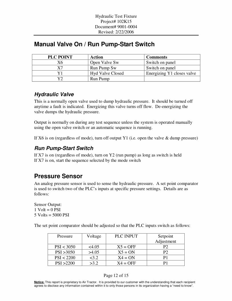
Manual Valve On / Run Pump-Start Switch
PLC POINT Action Comments
X6 Open Valve Sw Switch on panel
X7 Run Pump Sw Switch on panel
Y1 Hyd Valve Closed Energizing Y1 closes valve
Y2 Run Pump
Hydraulic Valve
This is a normally open valve used to dump hydraulic pressure. It should be turned off
anytime a fault is indicated. Energizing this valve turns off flow. De-energizing the
valve dumps the hydraulic pressure.
Output is normally on during any test sequence unless the system is operated manually
using the open valve switch or an automatic sequence is running.
If X6 is on (regardless of mode), turn off output Y1 (i.e. open the valve & dump pressure)
Run Pump-Start Switch
If X7 is on (regardless of mode), turn on Y2 (run pump) as long as switch is held
If X7 is on, start the sequence selected by the mode switch
Pressure Sensor An analog pressure sensor is used to sense the hydraulic pressure. A set point comparator
is used to switch two of the PLC’s inputs at specific pressure settings. Details are as
follows:
Sensor Output:
1 Volt = 0 PSI
5 Volts = 5000 PSI
The set point comparator should be adjusted so that the PLC inputs switch as follows:
Pressure Voltage PLC INPUT Setpoint
Adjustment
PSI < 3050 <4.05 X5 = OFF P2
PSI >3050 >4.05 X5 = ON P2
PSI < 2200 <3.2 X4 = ON P1
PSI >2200 >3.2 X4 = OFF P1
Hydraulic Test Fixture
Project# 102K15
Document# 9001-0004
Revised: 2/22/2006
Page 13 of 15
Notice: This report is proprietary to Air Tractor. It is provided to our customer with the understanding that each recipient agrees to disclose any information contained within it to only those persons in its organization having a “need to know”.
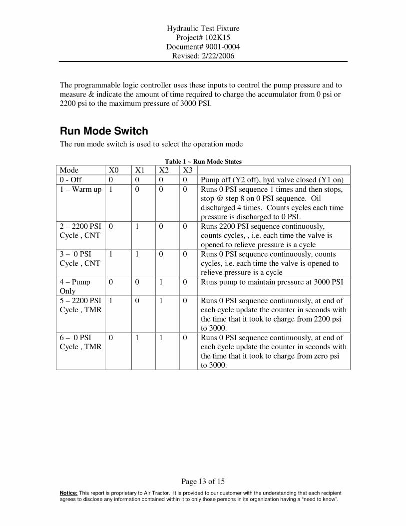
The programmable logic controller uses these inputs to control the pump pressure and to
measure & indicate the amount of time required to charge the accumulator from 0 psi or
2200 psi to the maximum pressure of 3000 PSI.
Run Mode Switch The run mode switch is used to select the operation mode
Table 1 ~ Run Mode States
Mode X0 X1 X2 X3
0 - Off 0 0 0 0 Pump off (Y2 off), hyd valve closed (Y1 on)
1 – Warm up 1 0 0 0 Runs 0 PSI sequence 1 times and then stops,
stop @ step 8 on 0 PSI sequence. Oil
discharged 4 times. Counts cycles each time
pressure is discharged to 0 PSI.
2 – 2200 PSI
Cycle , CNT
0 1 0 0 Runs 2200 PSI sequence continuously,
counts cycles, , i.e. each time the valve is
opened to relieve pressure is a cycle
3 – 0 PSI
Cycle , CNT
1 1 0 0 Runs 0 PSI sequence continuously, counts
cycles, i.e. each time the valve is opened to
relieve pressure is a cycle
4 – Pump
Only
0 0 1 0 Runs pump to maintain pressure at 3000 PSI
5 – 2200 PSI
Cycle , TMR
1 0 1 0 Runs 0 PSI sequence continuously, at end of
each cycle update the counter in seconds with
the time that it took to charge from 2200 psi
to 3000.
6 – 0 PSI
Cycle , TMR
0 1 1 0 Runs 0 PSI sequence continuously, at end of
each cycle update the counter in seconds with
the time that it took to charge from zero psi
to 3000.

Hydraulic Test Fixture
Project# 102K15
Document# 9001-0004
Revised: 2/22/2006
Page 14 of 15
Notice: This report is proprietary to Air Tractor. It is provided to our customer with the understanding that each recipient agrees to disclose any information contained within it to only those persons in its organization having a “need to know”.
Cycle Descriptions
Table 2 ~ Auto Cycle Sequence for 0 PSI & 2200 PSI
Step Action Description 0 PSI Cycle 2200 PSI Cycle
1 Wait until RUN PUMP
switch (X7) on to start
cycle, Close hydraulic
valve (Y1=ON)
Discharge pressure to => P = 0 PSI P ≤ 2200 PSI
2 Turn on pump until
3000 PSI reached (X5
on) then turn the pump
(Y2) off
Charge pump to 3000
PSI
3 If CTR Mode then
Increment counter (Y4
on for .1 sec per
count), If TMR Mode
then display number of
seconds that pump was
on
Display time or count
4 Wait 5 seconds
5 Open Hyd Valve
(Y1=off) until =>
Discharge pressure to 0
or 2200 PSI depending
on mode selected
45 seconds X4=ON
Pressure=2200
PSI
6 Wait Wait depending on mode 15 seconds 60 seconds
7 Repeat 2 thru 6 a total
of 4 times
8 Wait 4 minutes
9 Go to step 1
Power / Cycle In Progress Light The status of the system is indicated by the Green power indicator.
PLC Output=Y0 (controls light)
System status is as follows:
Power On, no Cycle in Progress = Steady on
Power On and Cycle in Progress = Flashing
Hydraulic Test Fixture
Project# 102K15
Document# 9001-0004
Revised: 2/22/2006
Page 15 of 15
Notice: This report is proprietary to Air Tractor. It is provided to our customer with the understanding that each recipient agrees to disclose any information contained within it to only those persons in its organization having a “need to know”.
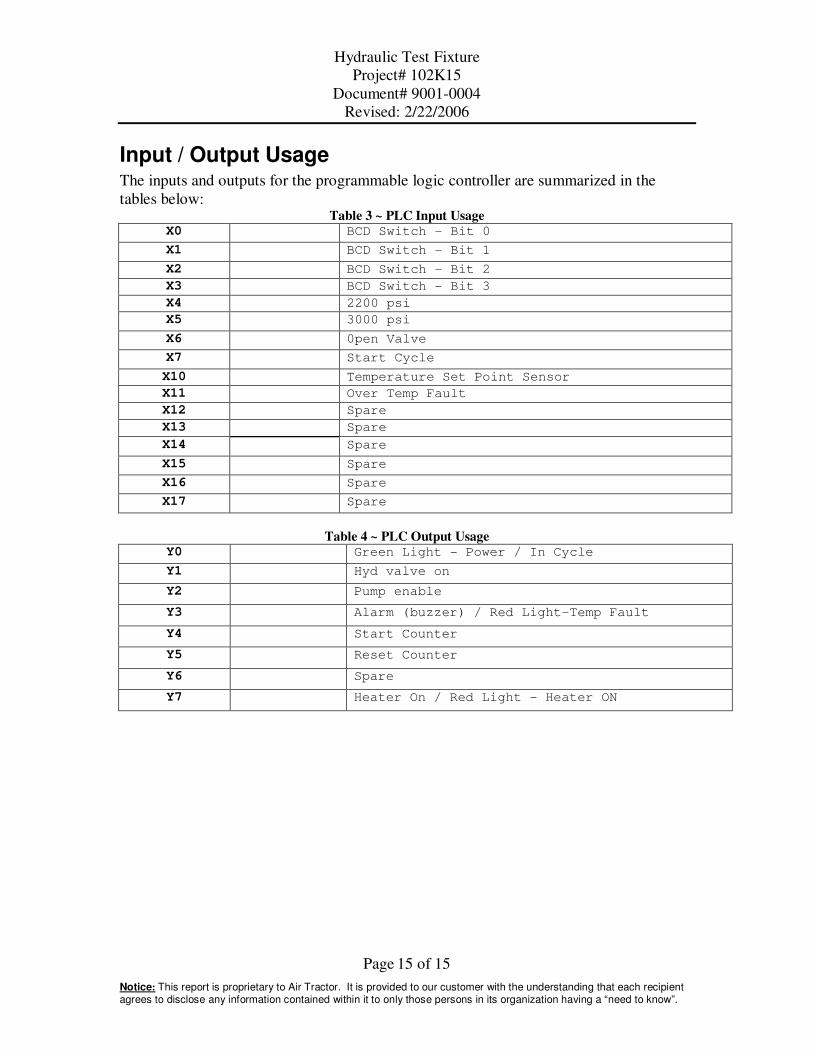
Input / Output Usage The inputs and outputs for the programmable logic controller are summarized in the
tables below: Table 3 ~ PLC Input Usage
X0 BCD Switch - Bit 0
X1 BCD Switch - Bit 1
X2 BCD Switch - Bit 2
X3 BCD Switch - Bit 3
X4 2200 psi
X5 3000 psi
X6 0pen Valve
X7 Start Cycle
X10 Temperature Set Point Sensor
X11 Over Temp Fault
X12 Spare
X13 Spare
X14 Spare
X15 Spare
X16 Spare
X17 Spare
Table 4 ~ PLC Output Usage Y0 Green Light - Power / In Cycle
Y1 Hyd valve on
Y2 Pump enable
Y3 Alarm (buzzer) / Red Light-Temp Fault
Y4 Start Counter
Y5 Reset Counter
Y6 Spare
Y7 Heater On / Red Light - Heater ON