900ma/mam and 1000ma/mam900ma_and...900ma/mam and 1000ma/mam (for marine applications) fuel...
TRANSCRIPT
900MA/MAM and 1000MA/MAM (for marine applications)Fuel Filter/Water Separator
Contact InformationParker Hannifin CorporationRacor DivisionP.O. Box 32083400 Finch RoadModesto, CA 95353
Phone 800 344 3286 209 521 7860Fax 209 529 3278Email [email protected] parker.com/racor
Instruction Part Number 19526 Rev B
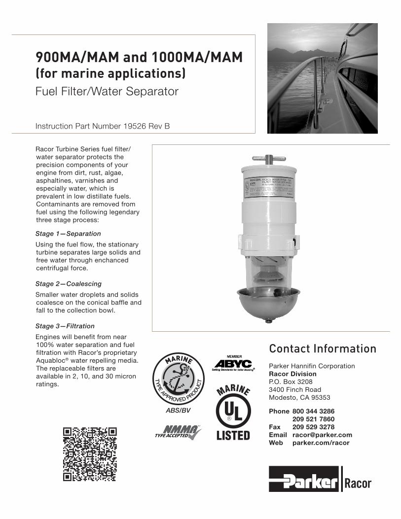
Racor Turbine Series fuel filter/water separator protects the precision components of your engine from dirt, rust, algae, asphaltines, varnishes and especially water, which is prevalent in low distillate fuels. Contaminants are removed from fuel using the following legendary three stage process:
Stage 1—Separation
Using the fuel flow, the stationary turbine separates large solids and free water through enchanced centrifugal force.
Stage 2—Coalescing
Smaller water droplets and solids coalesce on the conical baffle and fall to the collection bowl.
Stage 3—Filtration
Engines will benefit from near 100% water separation and fuel filtration with Racor’s proprietary Aquabloc® water repelling media. The replaceable filters are available in 2, 10, and 30 micron ratings.
MARINE
TY
PE APPROVED PROD
UC
T
ABS/BV
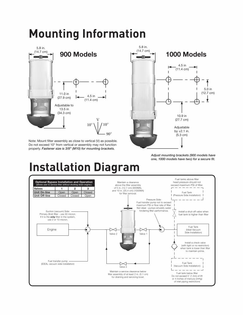
Mounting Information
90°
10° 10°V
Note: Mount filter assembly as close to vertical (V) as possible. Do not exceed 10° from vertical or assembly may not function properly. Fastener size is 3/8" (M10) for mounting brackets.
1000 Models
10.9 in(27.7 cm)
Adjustable by ±2.1 in.
(5.3 cm)
4.5 in(11.4 cm)
5.8 in.(14.7 cm)
5.0 in(12.7 cm)
900 Models
11.0 in(27.9 cm)
Adjustable to 13.5 in
(34.3 cm)
5.8 in.(14.7 cm)
4.5 in(11.4 cm)
Maintain a service clearance belowfilter assembly of at least 2 in. (5.1 cm)
for draining and servicing bowl.
Optional Bypass Installation and Operation(allows user to service filter without shutting down engine.)
Valves 1 2 3Unit On-line Open Open ClosedUnit Off-line Closed Closed Open
Installation Diagram
Valve 1Valve 2
Fuel tanks above filterhead pressure should not
exceed maximum PSI of filter.
Fuel Tank(Pressure Side Installation)
Install a shut-off valve when fuel tank is higher than filter
Fuel tank below filterDo not exceed 5’ (1.5m) of liftor 4 inches of mercury (inHg)
of inlet piping restrictions
Fuel Tank(Ideal Vacuum
Side Installation)
Fuel Tank(Vacuum Side Installation)
Install a check valve (with light or no restriction)
when tank is lower than filterto maintain prime.
Pressure Side:Fuel transfer pump not to exceed maximum PSI or flow rate of filter. Not ideal - pumps emulsify water
hindering filter performance.
Fuel transfer pump(IDEAL vacuum side installation)
Engine
Valve 3
Suction (vacuum) Side: Primary (first) filter - use 30 micron.If it is the only filter in the system,
use 2 or 10 micron.
Maintain a clearance above the filter assembly
of 5 in. (12.7 cm) (900MA), and 10 in. (25.4 cm) (1000MA)
for filter removal.
Adjust mounting brackets (900 models have one, 1000 models have two) for a secure fit.
Installation GuidelinesThese customer supplied materials should be on hand before beginning installation.
• Shop Towels
• Mounting Hardware (3/8”)
• Inlet/Outlet Fittings
• Fuel Hose
• Clean Diesel Fuel (about 1 gal.)
• Clean Motor Oil
• Thread Sealant (no thread tapes)
Positioning The Filter Assembly
Install filter assembly on suction side of fuel transfer pump for optimum water separating efficiency. See Installation Diagram.
Keep fuel line restrictions to a minimum. Locate the filter assembly between horizontal planes of the bottom of the fuel tank and inlet of fuel pump, if possible. If filter assembly is installed in an application where the fuel tank is higher than the filter, a shut-off valve must be installed between the tank and filter assembly INLET. This will be used when servicing the replacement filter.
BEFORE Installing The Filter Assembly
• Obtain good ventilation and lighting.
• Maintain a safe working environment.
• Engine must be off for installation.
• DO NOT smoke or allow open flames near installation.
Installing The Filter Assembly
•Completelyremoveanysuctionside filters in fuel system between fuel tank and fuel pump. This is where the Racor filter will mount. Leaving these filters in place will add to fuel system restriction. Filter heads cast into the engine or that are non-removable or hard piped should be serviced with a new filter and left in place.
•Keepfuelflowrestrictionto a minimum. Always use the maximum size fuel hose possible. Do not make sharp bends with flexible hose as kinks may occur. Avoid use of two 45° elbow fittings where one 90° elbow will work.
•Whenroutinghose,avoidsurfaces that move, have sharp edges, or get hot (such as exhaust piping).
•Avoidusingone-waycheckvalves that have an opening pressure higher than 0.5 PSI (0.03 bar).
Priming Instructions1. Remove T-handle and lid from
top of filter assembly.
2. Fill filter with clean fuel.
3. Lubricate lid gasket and T-handle O-ring with clean fuel or motor oil.
4. Replace lid and T-handle and tighten snugly by hand only—do not use tools.
5. If applicable, refer to equipment operator’s service manual to complete fuel priming procedure.
6. Start engine and check for fuel system leaks. Correct as necessary with engine off and pressure relieved from filter assembly.
Service InstructionsDraining WaterFrequency of water draining is determined by the contamination level of the fuel. Inspect or drain collection bowl of water daily or as necessary. Collection bowl must be drained before contaminants reach the bottom of the turbine (inside the bowl), or when the WaterDetectionModule(optional)indicates a drain is required.
Pressure Side Applications1. Open self-venting drain
on bottom of bowl. Head pressure will push any water and contaminants out of drain while keeping filter primed.
2. Close drain after all water and contaminants have been evacuated—DO NOT leave drain open too long as it will eventually completely drain entire filter of water AND fuel, and possibly drain entire tank.
Suction Side Applications1. Close inlet valve (or valve #1)
and open self-venting drain on bottom of bowl.
2. Close drain after all water and contaminants have been evacuated—DO NOT leave drain open too long as it will eventually completely drain entire filter of water AND fuel.
3. Follow Priming Instructions.
Frequency of filter replacement is determined by the contamination level of your fuel. Replace filter every 500 hours, every other oil change, when vacuum gauge (optional) reads between 7 to 10 inches of mercury (inHg), if power loss is noticed, or annually, whichever occurs first.
Note—always carry extra replacement filters as one tankful of excessively dirty fuel can plug a filter.
Use only genuine Racor Aquabloc® replacement filters—see Part List.
All Applications1. Isolate the filter assembly with
bypass or shut-off valves, if applicable.
2. Remove T-handle and lid.
3. Remove filters by holding bail handles and slowly pulling upward with a twisting motion. Dispose properly according to local regulations.
4. Remove and discard old lid gasket and T-handle O-ring and clean seal glands of any dirt or
debris. Lubricate new gasket and seal (supplied with new filter) with motor oil or diesel fuel before installation.
5. Refer to Priming Instructions, otherwise, fill unit with clean fuel, replace lid and T-handle and tighten snuggly by hand only—do not use tools.
6. Open any closed valves; if applicable.
Note—above ground tanks or transfer pump applications may use head pressure to prime filter assembly.
Filter Replacement
900MA or
900MAM
1000MA or
1000MAM
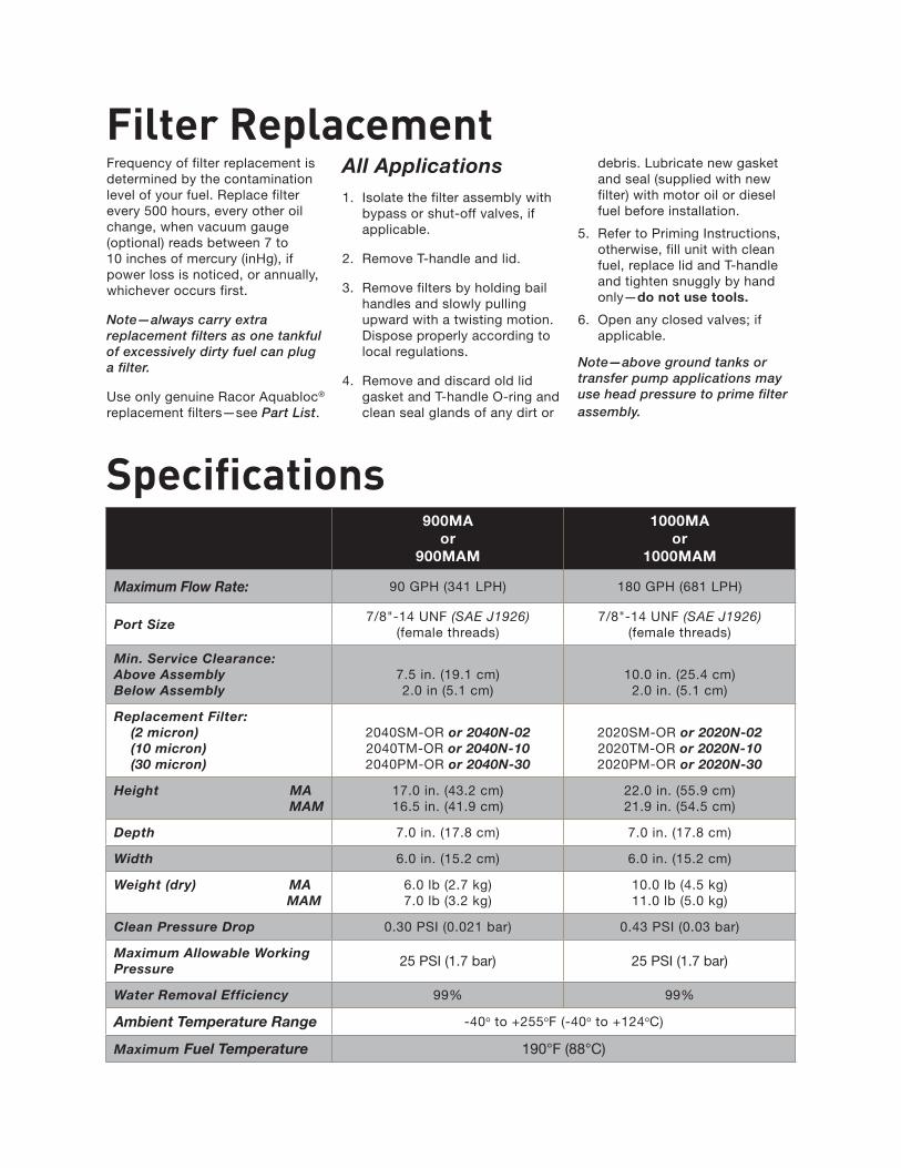
Maximum Flow Rate: 90 GPH (341 LPH) 180 GPH (681 LPH)
Port Size7/8"-14 UNF (SAE J1926)
(female threads)7/8"-14 UNF (SAE J1926)
(female threads)
Min. Service Clearance:Above AssemblyBelow Assembly
7.5 in. (19.1 cm)2.0 in (5.1 cm)
10.0 in. (25.4 cm)2.0 in. (5.1 cm)
Replacement Filter: (2 micron) (10 micron) (30 micron)
2040SM-OR or 2040N-022040TM-OR or 2040N-102040PM-OR or 2040N-30
2020SM-OR or 2020N-022020TM-OR or 2020N-102020PM-OR or 2020N-30
Height MA MAM
17.0 in. (43.2 cm) 16.5 in. (41.9 cm)
22.0 in. (55.9 cm) 21.9 in. (54.5 cm)
Depth 7.0 in. (17.8 cm) 7.0 in. (17.8 cm)
Width 6.0 in. (15.2 cm) 6.0 in. (15.2 cm)
Weight (dry) MA MAM
6.0 lb (2.7 kg) 7.0 lb (3.2 kg)
10.0 lb (4.5 kg) 11.0 lb (5.0 kg)
Clean Pressure Drop 0.30 PSI (0.021 bar) 0.43 PSI (0.03 bar)
Maximum Allowable Working Pressure 25 PSI (1.7 bar) 25 PSI (1.7 bar)
Water Removal Efficiency 99% 99%
Ambient Temperature Range -40o to +255oF (-40o to +124oC)
Maximum Fuel Temperature 190°F (88°C)
Specifications
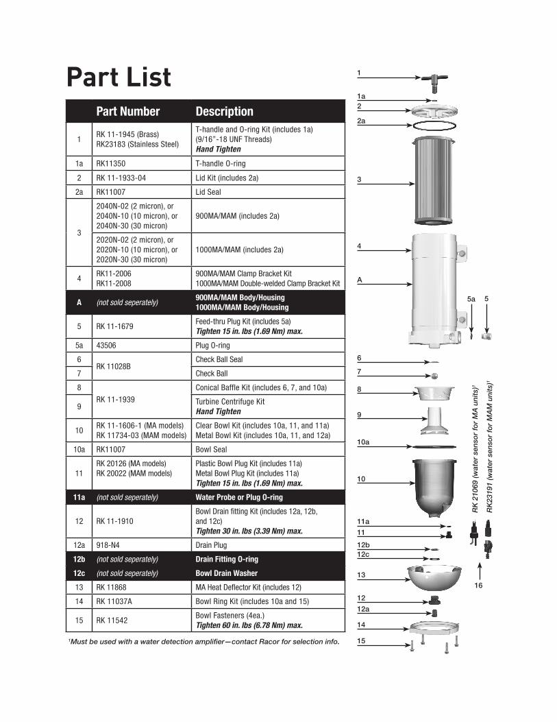
Part ListPart Number Description
1RK 11-1945 (Brass) RK23183 (Stainless Steel)
T-handle and O-ring Kit (includes 1a)(9/16”-18 UNF Threads)Hand Tighten
1a RK11350 T-handle O-ring
2 RK 11-1933-04 Lid Kit (includes 2a)
2a RK11007 Lid Seal
3
2040N-02 (2 micron), or 2040N-10 (10 micron), or 2040N-30 (30 micron)
900MA/MAM (includes 2a)
2020N-02 (2 micron), or 2020N-10 (10 micron), or 2020N-30 (30 micron)
1000MA/MAM (includes 2a)
4RK11-2006RK11-2008
900MA/MAM Clamp Bracket Kit1000MA/MAM Double-welded Clamp Bracket Kit
A (not sold seperately) 900MA/MAM Body/Housing1000MA/MAM Body/Housing
5 RK 11-1679Feed-thru Plug Kit (includes 5a)Tighten 15 in. lbs (1.69 Nm) max.
5a 43506 Plug O-ring
6RK 11028B
Check Ball Seal
7 Check Ball
8
RK 11-1939
Conical Baffle Kit (includes 6, 7, and 10a)
9Turbine Centrifuge KitHand Tighten
10RK 11-1606-1 (MA models) RK 11734-03 (MAM models)
Clear Bowl Kit (includes 10a, 11, and 11a) Metal Bowl Kit (includes 10a, 11, and 12a)
10a RK11007 Bowl Seal
11RK 20126 (MA models) RK 20022 (MAM models)
Plastic Bowl Plug Kit (includes 11a) Metal Bowl Plug Kit (includes 11a)Tighten 15 in. lbs (1.69 Nm) max.
11a (not sold seperately) Water Probe or Plug O-ring
12 RK 11-1910Bowl Drain fitting Kit (includes 12a, 12b, and 12c)Tighten 30 in. lbs (3.39 Nm) max.
12a 918-N4 Drain Plug
12b (not sold seperately) Drain Fitting O-ring
12c (not sold seperately) Bowl Drain Washer
13 RK 11868 MA Heat Deflector Kit (includes 12)
14 RK 11037A Bowl Ring Kit (includes 10a and 15)
15 RK 11542Bowl Fasteners (4ea.) Tighten 60 in. lbs (6.78 Nm) max.
1
1a2
2a
3
4
A
6
7
8
9
5a 5
10a
10
11a
11
12b12c
13
12
12a
14
151Must be used with a water detection amplifier—contact Racor for selection info.
RK
210
69 (w
ater
sen
sor
for
MA
uni
ts)1
RK
2319
1 (w
ater
sen
sor
for
MA
M u
nits
)1
16
Troubleshooting
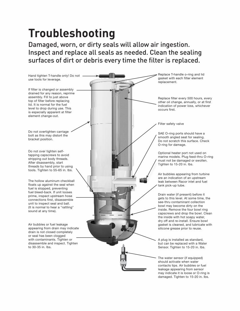
Replace filter every 500 hours, every other oil change, annually, or at first indication of power loss, whichever occurs first.
Do not over tighten self-tapping capscrews to avoid stripping out body threads. After disassembly, start threads by hand prior to using tools. Tighten to 55-65 in. lbs.
The hollow aluminum checkball floats up against the seal when fuel is stopped, preventing fuel bleed-back. If unit looses prime, inspect upstream hose connections first, disassemble unit to inspect seal and ball. (It is normal to hear a "rattling" sound at any time).
Air bubbles or fuel leakage appearing from drain may indicate drain is not closed completely or seal has been clogged with contaminants. Tighten or disassemble and inspect. Tighten to 30-35 in. lbs.
If filter is changed or assembly drained for any reason, reprime assembly. Fill to just above top of filter before replacing lid. It is normal for the fuel level to drop during use. This is especially apparent at filter element change-out.
Hand tighten T-handle only! Do not use tools for leverage.
SAE O-ring ports should have a smooth angled seat for sealing. Do not scratch this surface. Check O-ring for damage.
Damaged, worn, or dirty seals will allow air ingestion. Inspect and replace all seals as needed. Clean the sealing surfaces of dirt or debris every time the filter is replaced.
Do not overtighten carriage bolt as this may distort the bracket position.
Optional heater port not used on marine models. Plug feed-thru O-ring must not be damaged or swollen. Tighten to 15-20 in. lbs.
Air bubbles appearing from turbine are an indication of an upstream leak between Racor inlet and fuel tank pick-up tube.
A plug is installed as standard, butcanbereplacedwithaWaterSensor. Tighten to 15-20 in. lbs.
The water sensor (if equipped) should activate when water contacts tips. Air bubbles or fuel leakage appearing from sensor may indicate it is loose or O-ring is damaged. Tighten to 15-20 in. lbs.
Filter safety valve
Drain water (if present) before it gets to this level. At some time, the see-thru contaminant collection bowl may become dirty on the inside. Remove the four bowl ring capscrews and drop the bowl. Clean the inside with hot soapy water, dry off and re-install. Ensure bowl gasket is cleaned, and lubricate with silicone grease prior to reuse.
Replace T-handle o-ring and lid gasket with each filter element replacement.
TroubleshootingNote—Correct external fuel leaks immediately! These conditions are dangerous and are a fire hazard. Additionally, reduced engine performance such as: hard starting, stalling, reduced power, and other associated problems will result.
New filter installations must be filled with fuel and fuel system must be adequately primed following the engine manufacturer’s recommendations, if applicable. Existing installation difficulties are usually associated with improper priming procedures or damage to the unit or fuel system. The result is either internal air suction or external fuel leakage. Diagnosis should be in these following steps:
1. Check fuel tank level and make sure any fuel delivery valves are in open position, as applicable.
2. Ensure T-handle, bowl fasteners, and fuel fittings are tight. Also verify that bowl drain is closed.
3. If filter is new, check potential restriction at fuel tank draw tube. An in-tank strainer may be plugged.
Correct Application—It is very important that filter is not ‘under specified’ for the application. The maximum fuel flow rating of filter must not be exceeded and engine manufactures maximum fuel inlet restriction, must not be exceeded. Doing so will reduce efficiency and de-gas (pull air from) fuel.
Filter—Replacement filters are available in 2, 10, and 30 micron ratings. Filtration needs are based on application, fuel quality, maintenance schedules, and operating climates. A simple rule to remember is, the finer the filtration (i.e. the smaller the number), the more frequent the filter change. Always carry extra replacement filters with your equipment as one tankful of excessively contaminated fuel can plug a filter.Whenclogged to the maximum capacity, filters will have a brown to black color or tar like contaminants may be present - this is normal. An appearance of a multi-colored slime (which may have a foul odor) is an indication of microbiological contamination. This condition must be treated immediately.
Severe conditions must be corrected by a repair facility.
Note—Never operate Racor unit without the filter in place - the 'filter safety valve' will not expose outlet hole on fuel return tube if filter is removed and fuel will not flow to engine. Instead, punch emergency tab on the top of filter and leave in place. Puncturing emergency tab will bypass all filtration and send unfiltered fuel to your engine. Service filter as soon as possible to avoid harmful contaminants flowing downstream to engine.
Water Sensors—This feature alerts operator of a high-water condition. The bowl is then drained of water at earliest convenience. Note - a Racor water detection module is needed to work
with the in-bowl sensor. The unit should activate when water reaches sensor tips (and when they measure between 47,000 and 100,000 ohms of resistance, depending on detection module used.) If not, tips may be fouled with a coating. Remove water sensor and clean tips with a cloth. Run a jumper wire between tips with ignition ON to test system. Difficulties usually lie in the wire connections, power source, or an independent ground.
All Racor filter assemblies are 100% tested to ensure a leak-proof, quality product.
Note—Correct external fuel leaks immediately! In the event difficulties are experienced with your filter assembly or a problem appears to prevent the engine from running smoothly, refer to the procedures on the previous page. Note—Apply Parker Super O-lube (part number RK 31605) or equivalent to all seals at major attachment points to maintain integrity, seal elasticity, to fill small voids, and to provide protection from degradation.
Perform all checks with engine OFF (and applicable valves closed). For replacement parts, refer to the Part List section of this manual.
March 2013© Parker Hannifin Corporation
All products manufactured or distributed by Racor are subject to the following, and only the following, LIMITED EXPRESS WARRANTIES, and no others: For a period of one (1) year from and after the date of purchase of a new Racor product, Racor warrants and guarantees only to the original purchaser-user that such a product shall be free from defects of materials and workmanship in the manufacturing process. The warranty period for pumps and motors is specifically limited to ninety (90) days from date of purchase. A product claimed to be defective must be returned to the place of purchase. Racor, at its sole option, shall replace the defective product with a comparable new product or repair the defective product. This express warranty shall be inapplicable to any product not properly installed and properly used by the purchaser-user or to any product damaged or impaired by external forces.
THIS IS THE EXTENT OF WARRANTIES AVAILABLE ON THIS PRODUCT. RACOR SHALL HAVE NO LIABILITY WHATSOEVER FOR CONSEQUENTIAL DAMAGES
FLOWING FROM THE USE OF ANY DEFECTIVE PRODUCT OR BY REASON OF THE FAILURE OF ANY PRODUCT. RACOR SPECIFICALLY DISAVOWS ALL OTHER WARRANTIES, EXPRESS OR IMPLIED INCLUDING, WITHOUT LIMITATION, ALL WARRANTIES OF FITNESS FOR A PARTICULAR PURPOSE (EXCEPT FOR THOSE WHICH APPLY TO PRODUCT OR PART THEREOF THAT IS USED OR BOUGHT FOR USE PRIMARILY FOR PERSONAL, FAMILY, OR HOUSEHOLD PURPOSES), WARRANTIES OF DESCRIPTION, WARRANTIES OF MERCHANTABILITY, TRADE USAGE OR WARRANTIES OR TRADE USAGE.
Warning
Failure or improper selection or improper use of the products and/or systems described herein or related items can cause death, personal injury and property damage. This document and other information from Parker Hannifin Corporation, its subsidiaries and authorized distributors provide product
and/or system options for further investigation by users having technical expertise. It is important that you analyze all aspects of your application and review the information concerning the product or system in the current product catalog. Due to the variety of operating conditions and applications for these products or systems, the user, through its own analysis and testing, is solely responsible for making the final selection of the products and systems and assuring that all performance, safety and warning requirements of the applications are met. The products described herein, including with limitation, product features, specifications, designs, availability and pricing, are subject to change by Parker Hannifin Corporation and its subsidiaries at any time without notice.
The following statement is required pursuant to proposition 65, applicable in the State of California: ‘This product may contain a chemical known to the State of California to cause cancer or reproductive toxicity’.
Limited Warranties Statement