9346-26 refractive beam shapers for optical systems … · refractive beam shapers for optical...
TRANSCRIPT
Refractive beam shapers for optical systems of lasers
Alexander Laskina, Vadim Laskina, Aleksei Ostrunb
a AdlOptica GmbH, Rudower Chaussee 29, 12489 Berlin, Germany b St. Petersburg National Research University of Information Technologies,
Mechanics and Optics, Kronverkskiy pr., 49, 197101, St.Petersburg, Russia,
ABSTRACT
Performance of modern high-power lasers can be strongly improved by control of irradiance distribution in laser optical systems: flat-top or super-Gaussian irradiance profiles are optimum for amplification in MOPA lasers and for reduction of thermal effects in crystals of solid-state ultra-short pulse lasers; variable profiles are also important in irradiating of photocathode of Free Electron lasers (FEL). This task can be easily solved with using beam shaping optics, for example,
the field mapping refractive beam shapers like Shaper. The operational principle of these devices presumes
transformation of laser beam intensity from Gaussian to flattop one with high flatness of output wavefront, saving of beam consistency, providing collimated output beam of low divergence, high transmittance, extended depth of field, negligible residual wave aberration, and achromatic design provides capability to work with ultra-short pulse lasers
having broad spectrum. With using the same Shaper it is possible to realize various beam profiles like flattop, inverse
Gauss or super Gauss by simple variation of input beam diameter. This paper will describe some design basics of refractive beam shapers of the field mapping type and optical layouts of their applying in optical systems of high-power lasers. Examples of real implementations and experimental results will be presented as well. Keywords: beam shaping, flat-top, tophat, superGauss, MOPA laser, short pulse laser, FEL, homogenizing.
1. INTRODUCTION By building modern Free Electron Lasers (FEL) as well as high power solid-state laser systems it is required effective
and flexible transformation of transverse intensity distribution to optimize irradiation of FEL photocathodes, optical
pumping and amplification in MOPA designs1-4.
Performance of a photoinjector can be seriously improved when a photocathode is irradiated by a beam with flattop
intensity profile. To provide specific features of an electron beam it is advisable also to have certain flexibility in
characteristics of laser spot on a photocathode: variable spot size, variable intensity profile with possibility to realize not
only flattop but also super-Gauss and inverse-Gauss profiles. To meet the protection requirements a photocathode should
be located at distances of several meters from a laser, therefore an optical system should provide possibility to transfer
the intensity profile over large distances. This can be realized by optical system of relatively simple design when light
beams have low divergence.
A common problem when optical pumping of crystals of solid-state lasers, for example Ti:Sapphire crystal with
multimode radiation of second harmonic of Nd:YAG, is high peak intensity in the crystal centre that leads to thermal
lensing and danger of the Ti:Sapphire crystal damage. As result there are limitations of quality and achievable output
laser power of ultra-short pulse laser, instability of laser operation. Transforming of that pumping beam to a beam of
uniform of intensity or even providing a “concave” (or “inverse-Gauss”) intensity distribution helps to overcome those
problems and provide more efficient optical systems of solid-state lasers.
Similar positive effect of beam shaping is important in high power lasers built according to MOPA configuration. With
flattop or super-Gauss intensity profile of a beam after seed laser it is possible to achieve higher amplification of the
radiation in amplifier due to more efficient use of energy from a pump source, reduce the influence of thermal lensing.
As result the higher levels of output power as well as more reliable laser operation can be achieved.
Summarizing one can describe the requirements to beam shaping optics for high-power laser systems:
- high resistance to powerful laser radiation,
- high transmission,
- conserving the structure and low divergence of a laser beam,
- realizing beam shaping in general sense, i.e. not only beam homogenizing but also providing other profiles, like
super-Gauss, inverse-Gauss,
- it is highly desirable that the variety of these profiles can be realized with the same beam shaper,
- capability to work wit TEM00 and multimode laser sources,
- adaptability to conditions of particular laser system.
These specific conditions are perfectly fulfilled by the refractive field mapping beam shapers due to their unique
features: almost lossless intensity profile transformation, low output divergence, high transmittance and flatness of
output beam profile, extended depth of field, adaptability to real intensity profiles of TEM00 and multimode laser
sources. Combining of the refractive field mapping beam shapers with other optical components, like beam-expanders,
relay imaging lenses, anamorphic optics makes it possible to generate the laser spots of necessary shape, size and
intensity distribution.
2. DESCRIPTION OF FIELD MAPPING REFRACTIVE BEAM SHAPERS
2.1 Basics of optical design
Under the name “Beam Shaping” there are considered various optical techniques, including ones based on diffractive optical
elements, arrays of microlenses or prism, field mapping beam shaping with using mirrors or lenses with special surface
shapes5. Among various types of beam shaping the refractive field mapping systems like Shaper demonstrate best capabilities
to meet the above described requirements. The design principles of refractive beam shapers of the field mapping type are well-
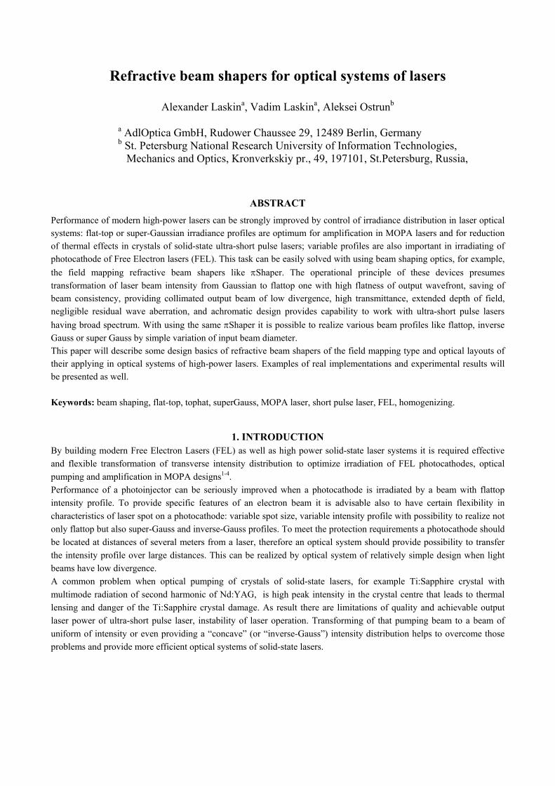
known and described in the literature5,9,10,11,12, one of implementations is presented in Fig. 1.
Figure 1 Refractive field mapping beam shaper Shaper
These beam shapers are typically built as telescopic systems with collimated beams at entrance and exit; they have two optical
components and transform the laser beam profile in a controlled manner, by accurate inducing of wave aberration by the
first component and further its compensation by the second one, Fig.1, top. The resulting collimated output beam has a uniform
intensity and flat wave front. It also has low divergence – almost the same like that of the input beam. In other words, the field
mapping beam shapers, like Shaper, transform the beam profile without deterioration of the beam consistency and without
increasing its divergence.
For the purpose of further considerations let us summarize main
optical features of Shaper systems being used in this work:
- refractive optical systems transforming Gaussian to
flattop (top-hat, uniform) irradiance distribution;
- almost 100% efficiency;
- high transmittance;
- transformation through controlled phase front
manipulation – 1st optical component introduces
spherical aberration required to re-distribute the
energy, then the 2nd optical component compensates
the aberration;
- output beam is free of aberrations, the phase profile
is maintained flat, hence, low divergence is
provided;
- TEM00 and multimode beams applied;
- collimated output beam,
- resulting beam profile is kept stable over large
distance;
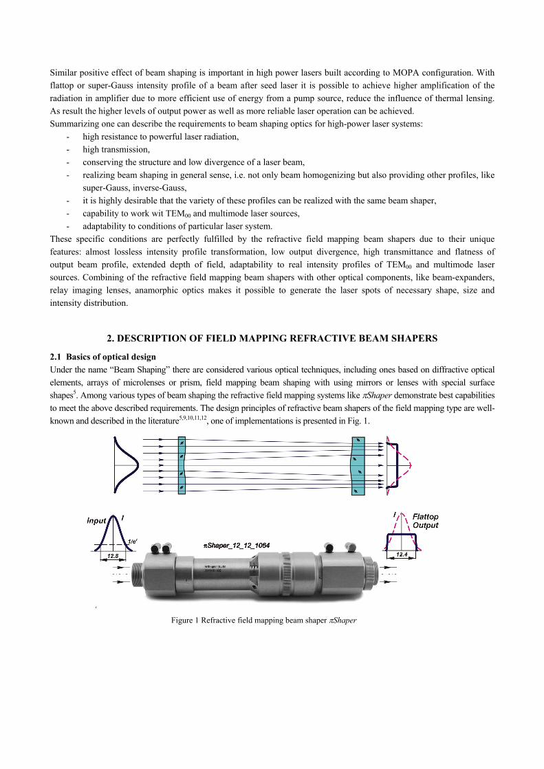
Figure 2 Example of beam shaping: left – Input TEM00 beam, right - after the Shaper
- implementations as telescopic or collimating optical systems;
- achromatic optical design, hence the beam shaping effect is provided for a certain spectral band simultaneously;
- Galilean design, no internal focusing.
Example of beam shaping for Nd:YAG laser is presented in Fig.2.
The achromatic design of the Shaper is inevitably required for ultra-short pulse laser with duration about 100 fs and less
– these lasers have relatively wide spectral band, up to several hundreds of nm, and providing the same conditions of
beam shaping for entire working bandwidth is very important.
The Galilean design of telescopic system guarantees avoidance of any internal focusing of a laser beam that is also very
important for reliable operation of a beam shaper with high peak power lasers.
2.2 Control of profiles
Operation principle refractive field mapping beam shapers presumes the input beam has a certain size (usually defined as
diameter at 1/e2 intensity level) and a certain intensity profile (Gaussian or similar profiles with peak intensity in the
centre). If an input beam size deviates from the pre-determined one the resulting profile varies as well. In other words, a
variation of input beam size corresponds to variation of output beam intensity distribution, and the size of the output
beam stays almost invariable. For example, when a Shaper is intended to convert the Gaussian beam to the flattop one
and the input beam is essentially smaller, say 2-3 times less than a specified value, the beam shaper operates as an
ordinary beam-expander and the resulting profile stays almost the same like at the entrance i.e. Gaussian. This effect is
discussed thoroughly in paper13 and is illustrated in Fig. 3 where measured in real experiments beam profiles are shown.

INPUT
OUTPUT
Figure 3 Experimental spot views and intensity profiles by beam shaping of TEM00 laser using Shaper 6_6: top - input beams with various diameters Din (1/e2), bottom – output beams.
Din = 6.2 mmDin = 5 mm Din = 7 mm

The data relate to the Shaper 6_6 which design presumes that a perfect Gaussian beam with 1/e2 diameter 6.2 mm to
be converted to a beam with uniform intensity (flattop) with FWHM diameter 6 mm.
When the input beam has a proper diameter Din = 6.2 mm, Fig.3 middle column, the resulting beam profile is flat-top,
Fig.3 middle bottom. But change of input beam size results in changing of the output beam profile: increasing of
diameter leads to a concave intensity distribution with minimum in the beam centre, Fig.3 right column, this distribution
is called “inverse-Gauss”; while beams size reduction allows to get a convex profile that approximately can be described
by super-Gauss functions, Fig.3 left column.
Evidently, a simple variation of laser input beam size allows to generate various profiles and this can be done with the
same beam shaper. To vary the beam diameter the ordinary beam expanders or imaging optical systems can be applied.
With using a zoom beam-expander one can steady vary the resulting beam profile and provide the intensity distributions
being optimum for particular optical systems of high power lasers. A remarkable feature is that variation of beam size at
the entrance of a refractive field mapping beam shaping system leads to variation of output intensity distribution but has
weak influence on the spot size, so the output beam has stable size but variable profile.
2.3 Creating square shaped flat-top beams
Optical designs of many laser systems presume using square shaped crystals, and to optimize the optical pumping or
amplification it is advisable to provide a flat-top beam with square shaped cross section. Design principle5,14 of refractive
beam shapers presumes operation with beams of circular symmetry, therefore output beam is round and square shape is
usually realized using a square mask and its further imaging in working space4. This approach works well but leads to
essential, up to 30%, energy losses; on the other hand image of a mask illuminated by highly coherent laser light is
characterized by pronounced diffraction side-lobes. Optimum solution in laser design applications of optical pumping or
amplification would be a beam with flat phase front, homogenized intensity, square shape of cross section and smooth
edges.
In case of using refractive field mapping beam shapers this
solution can be realized by use of birefringent optical
materials, for example crystals, to manufacture lenses of a
beam shaper. Then, by choosing optimum orientation of
polarization of a laser beam, wave plates and birefringent
lenses it is possible to redistribute lossless the laser energy
and provide square or other beam section shapes. To avoid
essential influence on a beam structure and disturbance of
its phase front it is advisable to use materials of weak
birefringence, for example uniaxial crystals with
orientation of crystal optical axis parallel to a beam shaper
optical axis.
Figure 4 Experimental intensity profiles when using a beam shaper with lenses made from birefringent materials: left – input TEM00 beam, right – square-shaped flat-top output.
This design approach is applied in Shaper models intended to be applied with high peak power short-pulse lasers –
lenses are made from sapphire, and due to coincidence of optical axes of crystal and whole beam shaper there exists a
tiny birefringence effect that allows realize square-shaped output beam, Fig.4. The edge smoothness depends on input
beam size; this point was considered in previous paragraph.
2.4 Imaging technique
When a TEM00 laser beam with Gaussian intensity distribution propagates in space its size varies due to inherent beam
divergence but the intensity distribution stays stable, this is a famous feature of TEM00 beams that is widely used in
practice. But this brilliant feature is valid for Gaussian beams only! When light beams with non-Gaussian intensity
distributions, for example flattop beams, propagate in space, they get simultaneously variation of both size and
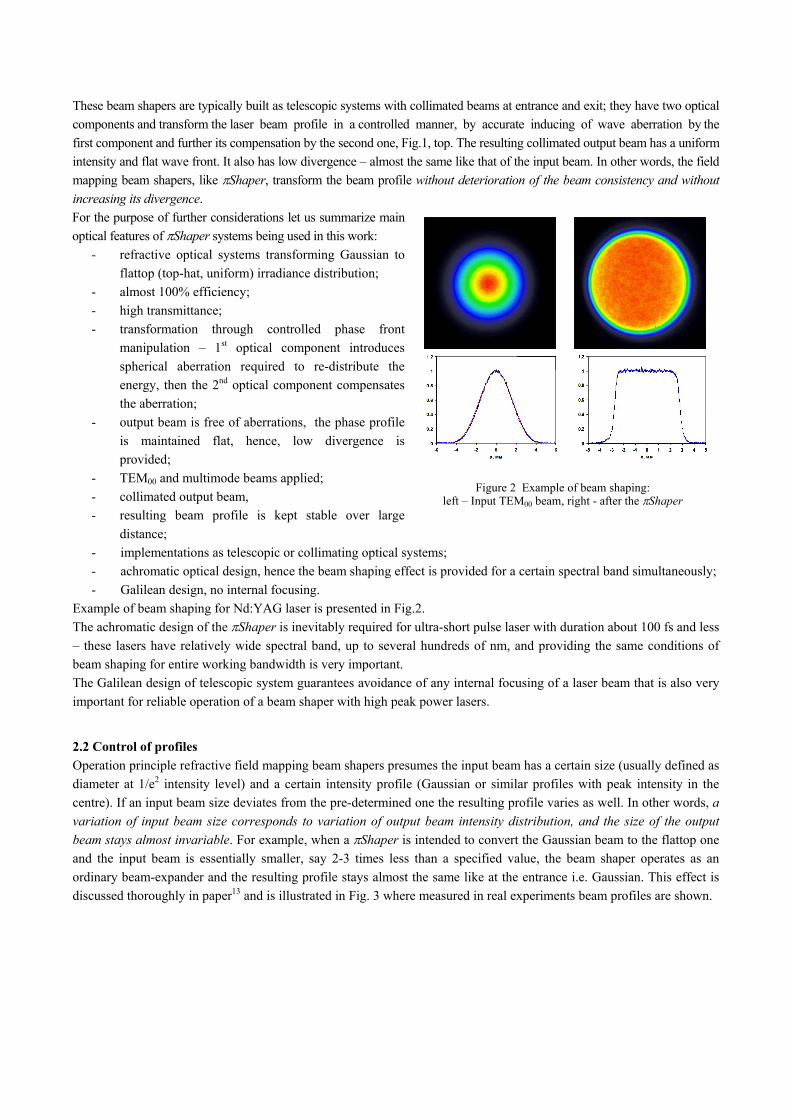
intensity profile. Suppose a coherent light beam has uniform intensity profile and flat wave front, Fig. 5, this is a
popular example considered in diffraction theory5-8, and is also a typical beam created by field mapping refractive
beam shapers converting Gaussian to flattop laser beam.
Figure 5 Intensity profile variation by a flattop beam propagation.
Due to diffraction the beam propagating in space gets variation of intensity distribution, some typical profiles are shown in Fig. 3: at certain distance from initial plane with uniform intensity distribution (a) there appears a bright rim (b) that is then transformed to more complicated circular fringe pattern (c), finally in infinity (so called far field) the profile is featured with relatively bright central spot and weak diffraction rings (d) – this is the well-known “Airy disk” distribution described mathematically by equation
2
10 2
2
JII (1)
where I is intensity, J1 is the Bessel function of 1st kind, 1st order, is polar radius, I0 is a constant. Evidently, a flat-top beam is transformed to a beam with essentially non-uniform intensity profile. There exists, however, certain propagation length where the profile is relatively stable, this length is in reverse proportion to wavelength and in square proportion to beam size. For example, for visible light, single mode initial beam and flattop beam diameter 6 mm after a Shaper 6_6 the length where deviation from uniformity doesn’t exceed +10% is about 200-300 mm, for the 12 mm beam it is about 1 meter. In case of considered here applications of optical pumping and amplification in designs of high-power lasers it is important to conserve a uniform intensity profile over certain distance. As a solution to the task of providing a necessary resulting spot size with conserving the flattop profile over extended DOF it is fruitful to apply imaging techniques. Essential features of this approach are considered in paper15, here we emphasize on most important for practice aspects and consider telecentric imaging system shown in Fig. 6, which is also called as a relay imaging system.
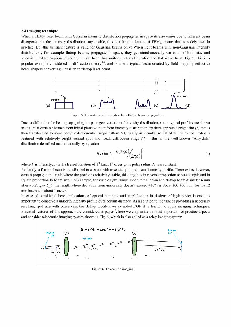
Figure 6 Telecentric imaging.
(a) (b) (c) (d)
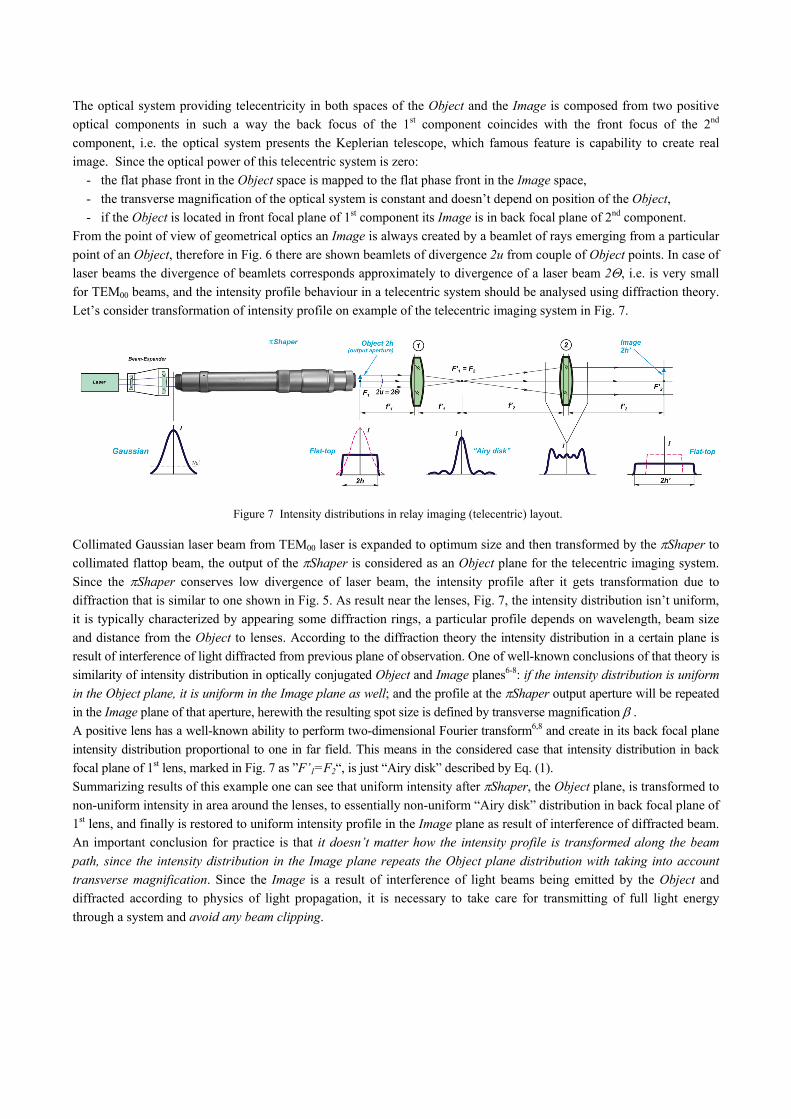
The optical system providing telecentricity in both spaces of the Object and the Image is composed from two positive
optical components in such a way the back focus of the 1st component coincides with the front focus of the 2nd
component, i.e. the optical system presents the Keplerian telescope, which famous feature is capability to create real
image. Since the optical power of this telecentric system is zero:
- the flat phase front in the Object space is mapped to the flat phase front in the Image space,
- the transverse magnification of the optical system is constant and doesn’t depend on position of the Object,
- if the Object is located in front focal plane of 1st component its Image is in back focal plane of 2nd component.
From the point of view of geometrical optics an Image is always created by a beamlet of rays emerging from a particular
point of an Object, therefore in Fig. 6 there are shown beamlets of divergence 2u from couple of Object points. In case of
laser beams the divergence of beamlets corresponds approximately to divergence of a laser beam 2, i.e. is very small
for TEM00 beams, and the intensity profile behaviour in a telecentric system should be analysed using diffraction theory.
Let’s consider transformation of intensity profile on example of the telecentric imaging system in Fig. 7.
Figure 7 Intensity distributions in relay imaging (telecentric) layout.
Collimated Gaussian laser beam from TEM00 laser is expanded to optimum size and then transformed by the Shaper to
collimated flattop beam, the output of the Shaper is considered as an Object plane for the telecentric imaging system.
Since the Shaper conserves low divergence of laser beam, the intensity profile after it gets transformation due to
diffraction that is similar to one shown in Fig. 5. As result near the lenses, Fig. 7, the intensity distribution isn’t uniform,
it is typically characterized by appearing some diffraction rings, a particular profile depends on wavelength, beam size
and distance from the Object to lenses. According to the diffraction theory the intensity distribution in a certain plane is
result of interference of light diffracted from previous plane of observation. One of well-known conclusions of that theory is
similarity of intensity distribution in optically conjugated Object and Image planes6-8: if the intensity distribution is uniform
in the Object plane, it is uniform in the Image plane as well; and the profile at the Shaper output aperture will be repeated
in the Image plane of that aperture, herewith the resulting spot size is defined by transverse magnification . A positive lens has a well-known ability to perform two-dimensional Fourier transform6,8 and create in its back focal plane
intensity distribution proportional to one in far field. This means in the considered case that intensity distribution in back
focal plane of 1st lens, marked in Fig. 7 as ”F’1=F2“, is just “Airy disk” described by Eq. (1).
Summarizing results of this example one can see that uniform intensity after Shaper, the Object plane, is transformed to
non-uniform intensity in area around the lenses, to essentially non-uniform “Airy disk” distribution in back focal plane of
1st lens, and finally is restored to uniform intensity profile in the Image plane as result of interference of diffracted beam.
An important conclusion for practice is that it doesn’t matter how the intensity profile is transformed along the beam
path, since the intensity distribution in the Image plane repeats the Object plane distribution with taking into account
transverse magnification. Since the Image is a result of interference of light beams being emitted by the Object and
diffracted according to physics of light propagation, it is necessary to take care for transmitting of full light energy
through a system and avoid any beam clipping.

3. EXPERIMENTAL RESULTS OF BEAM SHAPING
In this chapter there are presented examples of beam shaping to enhance specifications of ultra-short pulse lasers by
improving pumping and optimizing conditions for amplification.
3.1 Improving optical pumping of Ti:Sapphire lasers
One of important applications of the refractive beam
shapers is homogenizing multimode radiation from 2nd
Harmonic Nd:YAG laser when pumping Ti:Sapphire
crystals to generate powerful ultrashort pulses. The well-
known problem of developing powerful femtosecond
lasers is high central peak of intensity distribution of a
532 nm multimode pumping laser that leads to
destroying of central part of a Ti:Sapphire crystal, this
limits, practically, a maximum power level. Evidently,
downing of intensity in the centre of the multimode
pumping beam would allow to overcome this obstacle in
reaching higher power of a femtosecond laser.
(a) (b)
Figure 8 Comparison of beam profiles of pumping laser: (a) multimode original beam, = 532 nm, (b) output of Shaper 12_12_532 (Courtesy of LOTIS)
Just this task can be successfully solved by a field mapping beam shaper; result of realization of this approach by one of
users is illustrated in Fig. 8.
Intensity distribution of the original multimode beam is quite far from the Gaussian function, it is rather flattop but with
a pronounced peak in centre of the beam, just this intensity peak is a source of such a problem like damaging of
Ti:Sapphire crystal. Applying of the beam shaper effects downing of intensity in central part of the beam and, hence,
eliminating of the central peak and providing more smooth beam profile being optimized for pumping of Ti:Sapphire
crystal. As result the output laser power as well as its stability was seriously enhanced.
3.2 Beam shaping in MOPA lasers
As an example of applying the
refractive beam shapers in MOPA
lasers one can consider the advanced
laser system LIFE Lifetest Facility in
LLNL, Fig. 9, used for testing the
damage threshold of optical
components of NIF.
To provide correct measurements of
damage threshold it was necessary to
realize several laser beams with
various wavelengths, pulse energies
and durations but with just flattop
intensity profiles. A complex laser
optical system was applied where the
radiation emitted by the oscillator, on
left side in Fig. 9, was transformed
using the Shaper to a beam of uniform Figure 9 MOPA laser system with Shaper after the oscillator.(Courtesy of LLNL)
intensity and then amplified using high power amplifiers to provide necessary testing modes of the optical components.
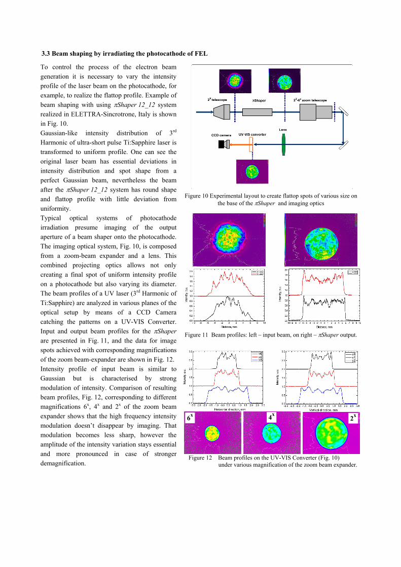
3.3 Beam shaping by irradiating the photocathode of FEL
To control the process of the electron beam
generation it is necessary to vary the intensity
profile of the laser beam on the photocathode, for
example, to realize the flattop profile. Example of
beam shaping with using Shaper 12_12 system
realized in ELETTRA-Sincrotrone, Italy is shown
in Fig. 10.
Gaussian-like intensity distribution of 3rd
Harmonic of ultra-short pulse Ti:Sapphire laser is
transformed to uniform profile. One can see the
original laser beam has essential deviations in
intensity distribution and spot shape from a
perfect Gaussian beam, nevertheless the beam
after the Shaper 12_12 system has round shape
and flattop profile with little deviation from
uniformity.
Typical optical systems of photocathode
irradiation presume imaging of the output
aperture of a beam shaper onto the photocathode.
The imaging optical system, Fig. 10, is composed
from a zoom-beam expander and a lens. This
combined projecting optics allows not only
creating a final spot of uniform intensity profile
on a photocathode but also varying its diameter.
The beam profiles of a UV laser (3rd Harmonic of
Ti:Sapphire) are analyzed in various planes of the
optical setup by means of a CCD Camera
catching the patterns on a UV-VIS Converter.
Input and output beam profiles for the Shaper
are presented in Fig. 11, and the data for image
spots achieved with corresponding magnifications
of the zoom beam-expander are shown in Fig. 12.
Intensity profile of input beam is similar to
Gaussian but is characterised by strong
modulation of intensity. Comparison of resulting
beam profiles, Fig. 12, corresponding to different
magnifications 6x, 4x and 2x of the zoom beam
expander shows that the high frequency intensity
modulation doesn’t disappear by imaging. That
modulation becomes less sharp, however the
amplitude of the intensity variation stays essential
and more pronounced in case of stronger
demagnification.
Figure 10 Experimental layout to create flattop spots of various size on
the base of the Shaper and imaging optics
Figure 11 Beam profiles: left – input beam, on right – Shaper output.
Figure 12 Beam profiles on the UV-VIS Converter (Fig. 10)
under various magnification of the zoom beam expander.
2x6x 4x

4. CONCLUSION
Spatial beam shaping is important in high power laser systems to improve irradiation of FEL photocathode, optical pumping of crystals or amplification in MOPA lasers. The lasers are characterized by ultra-short pulse durations and high peak power; therefore beam shaping optics should meet specific requirements like high transmission and resistance. Optimum beam shaping systems are built on the base of refractive field mapping beam shapers Shaper featured with low divergence, conservation of beam consistency, variable beam profiles, and operation with TEM00 and multimode beams. Being originally designed to transform Gaussian beams to beams of uniform intensity (flat-top) these beam shapers show high level of flexibility in generation of various intensity profiles like inverse-Gauss, super-Gauss, and this variety of transformations can be realized with using the same field mapping beam shaper. Refractive field mapping beam shapers made from homogeneous optical materials provide round flat-top output beam, but using of birefringent crystals makes it possible to generate square shaped output beam, thus realizing transformation of a round input TEM00 beam to square-shaped flat-top beam with smooth edges – all this properties are important to optimize optical pumping and amplification techniques.
5. REFERENCES
[1] Sharma, A. K., Tsang, T. & Rao, T., “Theoretical and experimental study of passive spatiotemporal shaping of picosecond laser pulse,” Physical Review ST AB 12, 033501 (2009).
[2] Tomizawa, H., Dewa, H., Taniuchi, T., Mizuno, A., Asaka, T., Yanagida, K., Suzuki, S., Kobayahsi, T., Hanaki, H. & Matsui, F., “Adaptive shaping system for both spatial and temporal profiles of a highly stabilized UV laser light source for a photocathode RF gun,” Nuclear Instrument and Methods A 557, 117, (2006).
[3] Will, I., Koss, G., Templin, I., “The upgraded photocathode laser of the TESLA Test Facility,” Nucl. Instrum. Meth. A 541(3), 467-477 (2005).
[4] Butcher, T., Mason, P., Banerjee, S., Pilar, J., Divoky, M., Smith, J., De Vido, M., Phillips, J., Ertel, K., Chekhlov, O., Tomlinson, S., Shaikh, W., Greenhalgh, J., Musgrave, I., Hernandez-Gomez, C., Collier, J., “Front End Design for a Temporally and Spatially Shaped 100 J Diode-Pumped Solid-State Laser,” Proc. OSA ASSL 2014, (2014).
[5] Dickey, F. M., [Laser Beam Shaping: Theory and Techniques, Second Edition], CRC Press, Boca Raton, (2014). [6] Goodman, J.W. [Introduction to Fourier Optics], McGraw-Hill, New York, (1996). [7] Born, M. and Wolf, E., [Principles of Optics], Pergamon Press, Oxford, 439-446 (1970). [8] Smith, W.J. [Modern Optical Engineering], McGraw-Hill, New York, (2000). [9] Hoffnagle, J. A., Jefferson, C. M., “Design and performance of a refractive optical system that converts a Gaussian
to a flattop beam,” Appl. Opt. vol. 39, 5488-5499 (2000). [10] Kreuzer, J., "Coherent light optical system yielding an output beam of desired intensity distribution at a desired
equiphase surface," US Patent 3476463, (1969). [11] Laskin, A. “Achromatic refractive beam shaping optics for broad spectrum laser applications,” Proc. SPIE 7430,
Paper 7430-2 (2009). [12] Laskin, A., “Achromatic Optical System for Beam Shaping,” US Patent 8023206, (2011). [13] Laskin, A., Laskin, V. “Variable beam shaping with using the same field mapping refractive beam shaper,” Proc.
SPIE 8236, Paper 82360D (2012). [14] Laskin, A., Laskin, V. “Applying of refractive beam shapers of circular symmetry to generate non-circular shapes
of homogenized laser beams,” Proc. SPIE 7913, Paper 7913-20 (2011). [15] Laskin, A.V., Laskin, V.V. “Imaging techniques with refractive beam shaping optics,” Proc. SPIE 8490, Paper
8490-19 (2012).
6. ACKNOWLEDGEMENTS
The authors grateful to users of Shaper in Lotis, LLNL and ELETTRA Sincrotrone for their active and patient work
with optics discussed in this paper and kind permission to publish some results achieved during their experiments.