980181-001c strata man · user’s manual no. 980181-001 rev. c ©1999 zebra technologies...
TRANSCRIPT
User’s Manual No. 980181-001 Rev. C
©1999 Zebra Technologies Corporation
StrataThermal Printers
User’s Manual

FOREWORD
This manual provides installation and operation information for the Eltron Strata LP (LP2684) andStrata TLP (TLP2684) printers, manufactured by Zebra Technologies Corporation, Camarillo,California.
COPYRIGHT NOTICE
This document contains information proprietary to Zebra Technologies Corporation. This docu-ment and the information contained within is copyrighted by Zebra Technologies Corporation andmay not be duplicated in full or in part by any person without written approval from Zebra. Whileevery effort has been made to keep the information contained within current and accurate as of thedate of publication, no guarantee is given or implied that the document is error-free or that it is ac-curate with regard to any specification. Zebra reserves the right to make changes, for the purpose ofproduct improvement, at any time.
TRADEMARKS
Strata, Strata LP , Strata TLP, LP2684 and TLP2684 are service marks and Eltron is a trademark ofZebra Technologies Corporation. Windows and MS-DOS are registered trademarks of MicrosoftCorp. All other marks are trademarks or registered trademarks of their respective holders.
FCC NOTICE:
This equipment has been tested and found to comply with the limits of a Class A digital device, pur-suant to Part 15 of the FCC Rules. These limits are designed to provide reasonable protectionagainst harmful interference when the equipment is operated in a commercial environment. Thisequipment generates, uses and can radiate radio frequency energy and, if not installed and used inaccordance with the instructions, may cause harmful interference to radio communications. How-ever, there is no guarantee that interference will not occur in a particular installation. Operation ofthis equipment in a residential area is likely to cause harmful interference in which case the user willbe required to correct the interference at his own expense.
INDUSTRY CANADA NOTICE:
This device complies with Industry Canada ICS-003 class A requirements.
Cet equipement est conforme a l’ICS-003 classe A de la norm Industrielle Canadian
980181-001 Rev.C iii

WARRANTY INFORMATION
We Need To Hear From You!To Establish Your Warranty Period And Provide Access To Technical Support,
Send Us Your Product Registration Card Today!
Zebra warrants the mechanism, control electronics and power supply, under normal use and ser-vice, to be free from defects in material and workmanship for a period of twelve (12) months fromthe date of purchase by the end user. Zebra warrants the print head, under normal use and service,to be free from defects in material and workmanship for a period of ninety (90) days or 30KM ofprinting (whichever occurs first) from the date of purchase by the end user. Proof of purchase orproduct registration is required. If proof of purchase or product registration cannot be established,shipment date to the original buyer (dealer or distributor) will be used to establish the warranty pe-riod.
Failure to exercise caution to protect the equipment from electrostatic discharge damage, adversetemperature and humidity conditions or physical abuse may void the warranty. Failure to use onlyZebra approved media may void the warranty. Zebra will, at its option, repair or replace the equip-ment or any parts which are determined to be defective within this warranty period, and which arereturned to Zebra F.O.B. factory of origin.
The warranty set forth above is exclusive and no other warranty, whether written or oral, is ex-pressed or implied. Zebra specifically disclaims the implied warranties of merchantability and fit-ness for a particular purpose.
RETURN MATERIALS AUTHORIZATION
Before returning any equipment to Zebra for in warranty or out of warranty repair, contact RepairAdministration for a Return Materials Authorization (RMA) number. Repack the equipment in theoriginal packing material and mark the RMA number clearly on the outside. Ship the equipment,freight prepaid, to the address listed below:
Zebra Repair Administration, USA1001 Flynn Road
Camarillo, CA. 93012Phone: +1 (805) 579-1800FAX: +1 (805) 579-1808
Label Printers: Card Printers:Zebra International, Europe Zebra International, Europe
Eltron House Zone Indutrielle, Rue d'AmsterdamMolly Millars Lane 44370 Varades, France
Wokingham RG41 2QZ England Phone: +33 (0) 240 097 070Phone: +44 (0) 1189 770 300 FAX: +33 (0) 240 834 745
FAX: +44 (0) 1189 895 762
iv 980181-001 Rev.C
Table of Contents
Installation . . . . . . . . . . . . . . . . . . . . . . . . . 1Introduction . . . . . . . . . . . . . . . . . . . . . . . . . . 1Unpacking Your Printer . . . . . . . . . . . . . . . . . . . . 2Installation . . . . . . . . . . . . . . . . . . . . . . . . . . . 3
Operation . . . . . . . . . . . . . . . . . . . . . . . . . . 7Your Printer . . . . . . . . . . . . . . . . . . . . . . . . . . 8The FEED Control . . . . . . . . . . . . . . . . . . . . . . . 10The STATUS Indicator. . . . . . . . . . . . . . . . . . . . . 12Loading Labelsor Tags. . . . . . . . . . . . . . . . . . . . . . . . . . . . . 13Loading Transfer Ribbons . . . . . . . . . . . . . . . . . . . 25Removing A Partially Used Transfer Ribbon . . . . . . . . . . 31Top Of Form Sensing . . . . . . . . . . . . . . . . . . . . . 32Using AutoSense. . . . . . . . . . . . . . . . . . . . . . . . 33Cleaning Your Printer . . . . . . . . . . . . . . . . . . . . . 35Cleaning the Print Head . . . . . . . . . . . . . . . . . . . . 36Cleaning Under the Sensor Bracket . . . . . . . . . . . . . . 37Using the Label Dispenser . . . . . . . . . . . . . . . . . . . 38
Troubleshooting . . . . . . . . . . . . . . . . . . . . . . . 41Where to Start . . . . . . . . . . . . . . . . . . . . . . . . . 41Other Support Resources . . . . . . . . . . . . . . . . . . . 44Serial Interface Communication Configuration. . . . . . . . . 45Serial Interface Cable Wiring. . . . . . . . . . . . . . . . . . 45Tag Media Sensing . . . . . . . . . . . . . . . . . . . . . . 46
Printer Features . . . . . . . . . . . . . . . . . . . . . . . 47
Supplies and Accessories . . . . . . . . . . . . . . . . . . 53
Using the Media Cutter . . . . . . . . . . . . . . . . . . . 57
980181-001 Rev.C v
General Cautions and Warnings
These pages describe general safety and maintenance warnings and cautions for the printer.They are referenced throughout the manual. The manual may also include other warnings andcautions not displayed here.
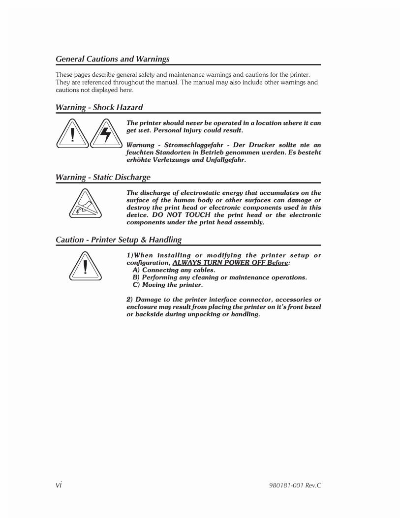
Warning - Shock Hazard
The printer should never be operated in a location where it canget wet. Personal injury could result.
Warnung - Stromschlaggefahr - Der Drucker sollte nie anfeuchten Standorten in Betrieb genommen werden. Es bestehterhöhte Verletzungs und Unfallgefahr.
Warning - Static Discharge
The discharge of electrostatic energy that accumulates on thesurface of the human body or other surfaces can damage ordestroy the print head or electronic components used in thisdevice. DO NOT TOUCH the print head or the electroniccomponents under the print head assembly.
Caution - Printer Setup & Handling
1)When installing or modifying the printer setup orconfiguration, ALWAYS TURN POWER OFF Before:
A) Connecting any cables.B) Performing any cleaning or maintenance operations.C) Moving the printer.
2) Damage to the printer interface connector, accessories orenclosure may result from placing the printer on it’s front bezelor backside during unpacking or handling.
vi 980181-001 Rev.C
Media Cautions & Tips
1) Always use high quality Eltron approved labels and tags.Eltron approved supplies can be ordered from your ELTRONdealer. For the name of a dealer in your area, call EltronCustomer Service at one of the numbers listed on the back pageof this manual.
2) If poor quality, adhesive backed labels are used, that DONOT lay flat on the backing liner, the exposed edges may stickto the label guides and rollers inside the printer, causing thelabel to peel off from the liner and jam the printer.
3) DO NOT use non-Eltron transfer ribbon. Permanent damageto the print head may result if a non-Eltron ribbon is used.Non-Eltron ribbons maybe wound incorrectly for the printer orcontain chemicals that may damage the print head.
4) IMPORTANT - If a transfer ribbon is installed incorrectly bythe operator, damage to the print head may result.
5) DO NOT use a ribbon when printing with direct thermalmedia.
Media Reload Tip
If you should run out of labels or ribbon while printing, DO NOTturn the power switch OFF (0) while reloading or data loss mayoccur. The printer will automatically resume printing when anew label or ribbon roll is loaded.
Print Mode Control (TLP2684)
The printer is reconfigured for direct thermal (or thermaltransfer) printing with the “O” command for the Strata TLPthermal transfer printer. See the EPL2 programmer's manualfor details.
Print Quality Tip
Print density (darkness) is affected by the heat energy (densitysetting) applied and by the print speed. Changing both PrintSpeed and Density may be required to achieve the desiredresults.
980181-001 Rev.C vii

viii 980181-001 Rev.C
1Installation
This section provides information on theinstallation of the printer and software.
Introduction The Strata printer models are low cost, manu-facturing oriented, thermal desktop printers.The Strata LP is a direct thermal printer. TheStrata TLP is a thermal transfer and direct ther-mal printer. The printers have been specificallydesigned for printing large labels, hazardousmaterial labels, small signs, fan-fold media, andshipping and receiving labels while operating inoffice to industrial environments.
The printer features sturdy construction, a smallfootprint, a heavy-duty motor, and sharp, reli-able printing up to 8.5 inches (216 mm) wide.The print head resolution of a Strata printer is203 dpi (8 dots/mm).
The printer can print letter (8.5”x 11”) and A4(210mm x 297mm) sizes. Print forms up to 8.5inches (216 mm) wide and 22 inches (558.8mm) long or two times A4 (210mm x 594mm)size with optional memory added.
980181-001 Rev.C 1
Installation
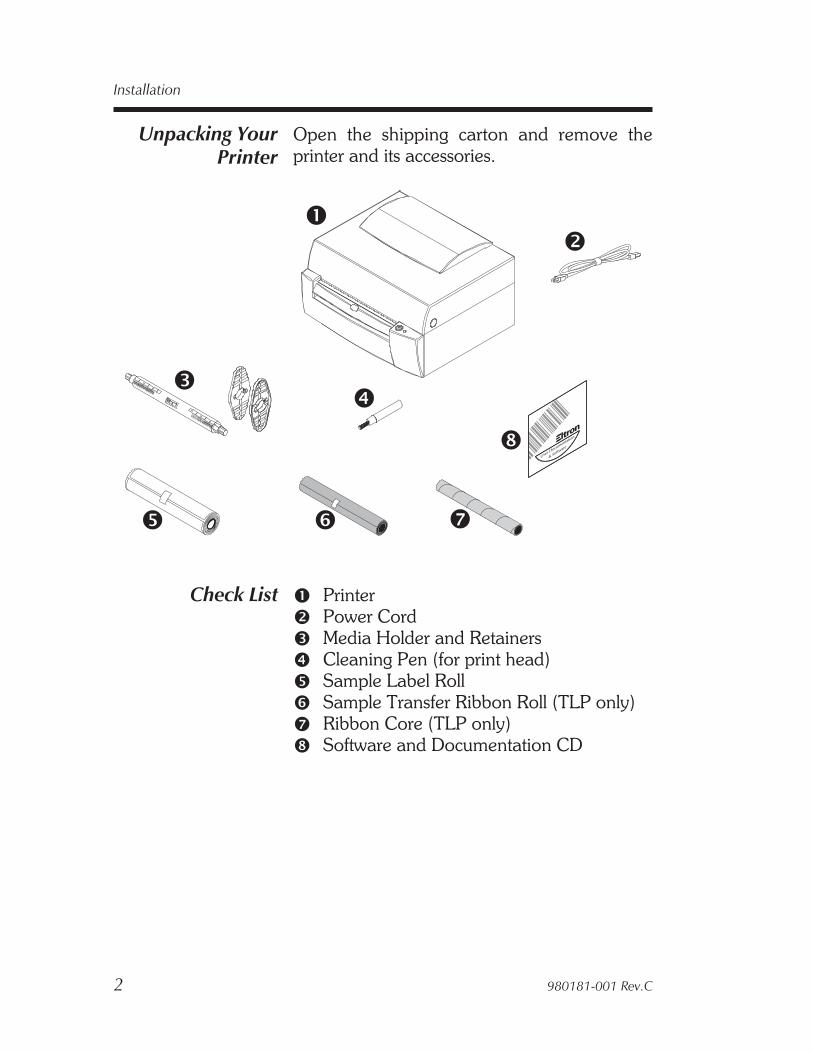
Unpacking YourPrinter
Open the shipping carton and remove theprinter and its accessories.
Check List 1 Printer2 Power Cord3 Media Holder and Retainers4 Cleaning Pen (for print head)5 Sample Label Roll6 Sample Transfer Ribbon Roll (TLP only)7 Ribbon Core (TLP only)8 Software and Documentation CD
2 980181-001 Rev.C
Installation
User Documentation
& Software
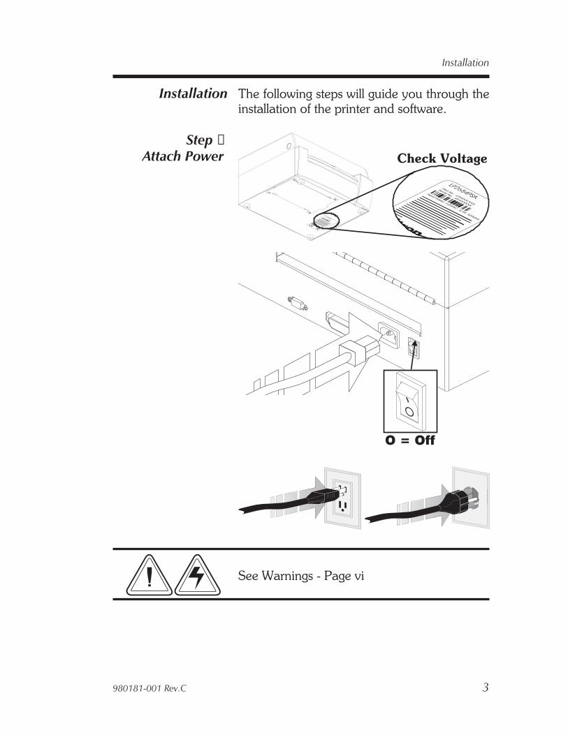
Installation The following steps will guide you through theinstallation of the printer and software.
Step ➊Attach Power
See Warnings - Page vi
980181-001 Rev.C 3
Installation
O
Part No. : 120XXX-XXX
Serial No. : XXXXXXXX
Input Power: 115VAC6.3A 50/60Hz
Part No. : 120XXX-XXX
Serial No. : XXXXXXXX
Input Power: 115VAC6.3A 50/60Hz
Check Voltage
O = Off
O
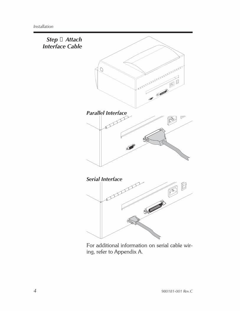
Step ➋ AttachInterface Cable
Parallel Interface
Serial Interface
For additional information on serial cable wir-ing, refer to Appendix A.
4 980181-001 Rev.C
Installation
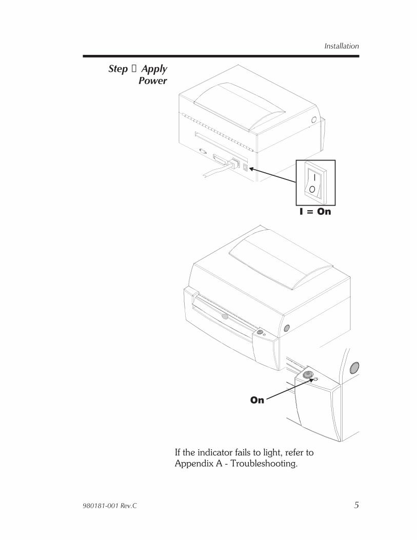
Step ➌ ApplyPower
If the indicator fails to light, refer toAppendix A - Troubleshooting.
980181-001 Rev.C 5
Installation
On
O
O
I = On
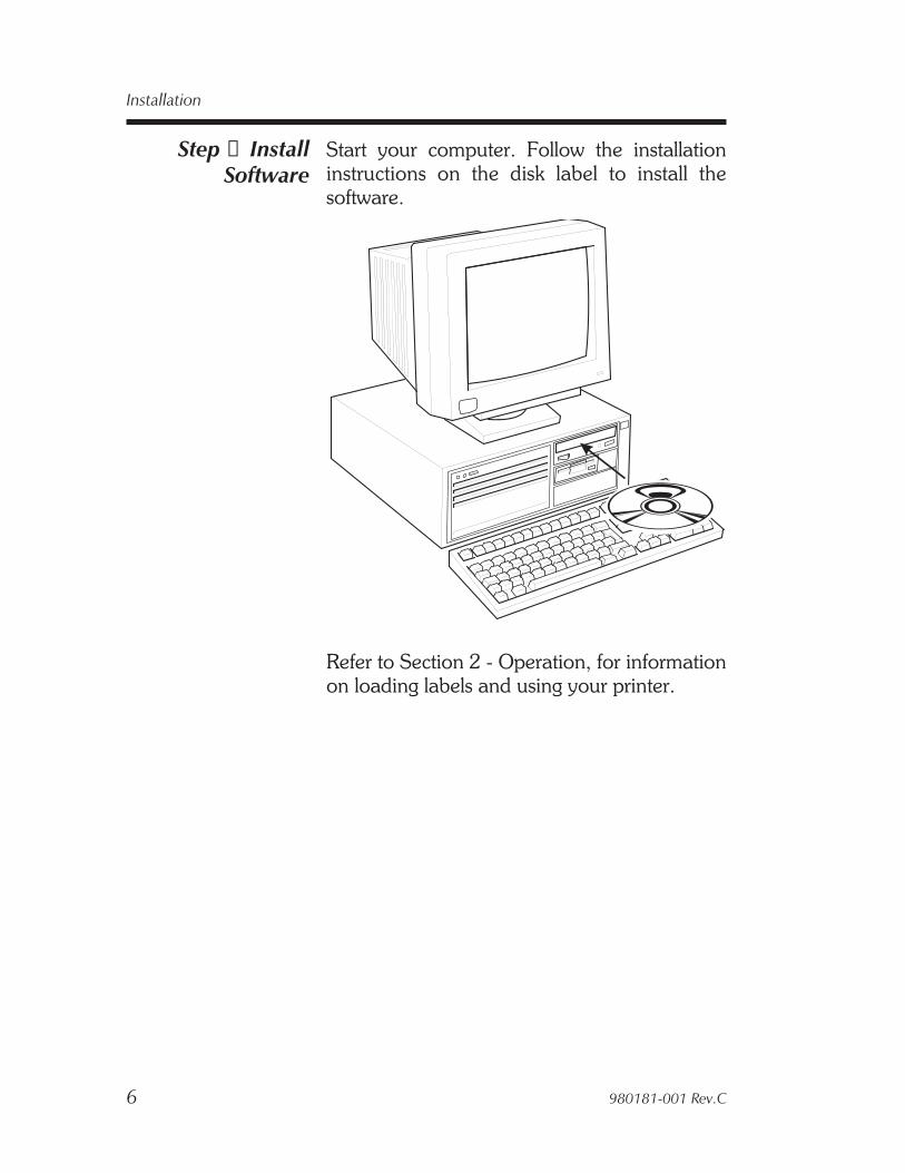
Step ➍ InstallSoftware
Start your computer. Follow the installationinstructions on the disk label to install thesoftware.
Refer to Section 2 - Operation, for informationon loading labels and using your printer.
6 980181-001 Rev.C
Installation
2Operation
This section provides information on the opera-tion of the printers.
All user control (and adjustment) printerfeatures are identified by green parts.
980181-001 Rev.C 7

Your Printer
1 Cover Release Buttons 8 Carriage Lock/Release Lever2 Feed Button 9 Media Guide Adjustment Gear3 Status Indicator : Transmissive (Gap) Sensor4 Media Roll Holder Adjustment Gear5 Media Roll Retainers ; Transmissive (Gap) Sensor6 Lower Media Stand Position Indicator
(Printing Position) < Reflective (Black Mark) Sensor7 Upper Media Stand = Platen Roller
(Loading Position) > Media Guides
8 980181-001 Rev.C
Operation
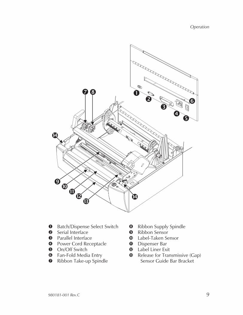
1 Batch/Dispense Select Switch 8 Ribbon Supply Spindle2 Serial Interface 9 Ribbon Sensor3 Parallel Interface : Label-Taken Sensor4 Power Cord Receptacle ; Dispenser Bar5 On/Off Switch < Label Liner Exit6 Fan-Fold Media Entry = Release for Transmissive (Gap)7 Ribbon Take-up Spindle Sensor Guide Bar Bracket
980181-001 Rev.C 9
Operation
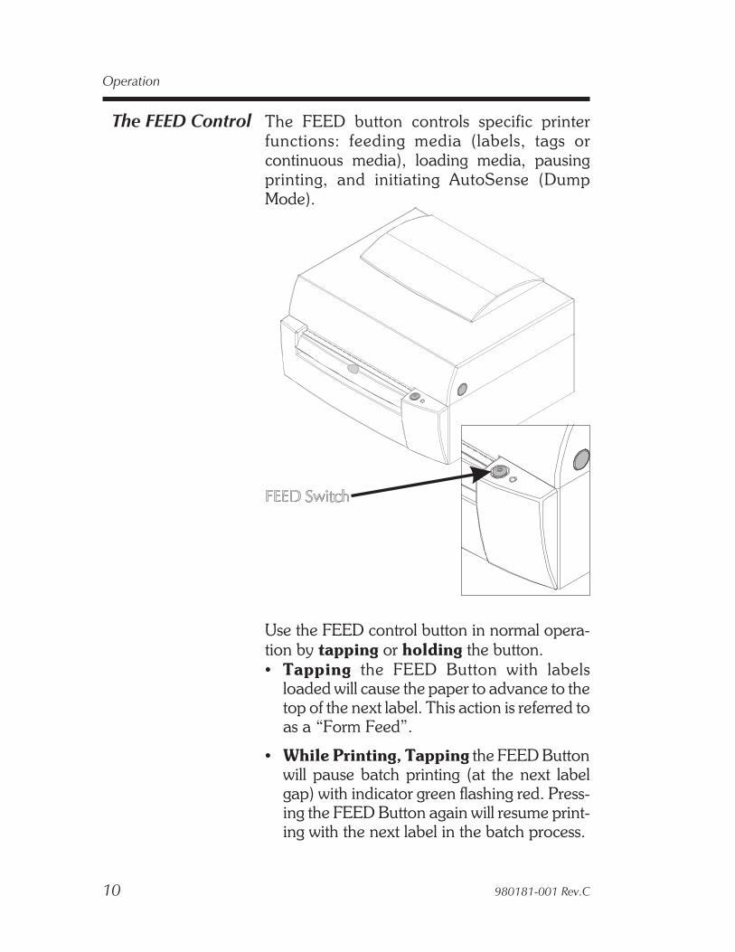
The FEED Control The FEED button controls specific printerfunctions: feeding media (labels, tags orcontinuous media), loading media, pausingprinting, and initiating AutoSense (DumpMode).
Use the FEED control button in normal opera-tion by tapping or holding the button.• Tapping the FEED Button with labels
loaded will cause the paper to advance to thetop of the next label. This action is referred toas a “Form Feed”.
• While Printing, Tapping the FEED Buttonwill pause batch printing (at the next labelgap) with indicator green flashing red. Press-ing the FEED Button again will resume print-ing with the next label in the batch process.
10 980181-001 Rev.C
Operation

• Holding the FEED button down will causethe printer to continuously Form Feed untilthe button is released. The printer will feedthe media until the next top of form isreached.
• Holding the FEED button without medialoaded will cause the printer to continuously(line) feed until the button is released or me-dia is detected. This is useful when reloadingmedia in the printer and is also known as“Power Media Loading”.
• Holding the FEED button down while pow-ering up the printer with media loaded willcause the printer to enter the AutoSensemode. See AutoSense on page 33 for impor-tant details.
Always run the AutoSense procedure whenloading new batch or type of media. Media fromthe same manufacturing lot and havingidentical dimensions do not need to have theAutoSense procedure run every time newmedia is loaded.
The Form Feed length is set by printerprogramming (Q) command in EPL2programming language or the AutoSensefeature, an automatic label and gap lengthsensing operation. See AutoSense, page 33.
Continuous media with no label gaps,containing black marks or notch holes, requireprogramming to set the form length and feeddistance.
980181-001 Rev.C 11
Operation

The STATUSIndicator
The STATUS indicator is a power and status in-dicator. When the printer power is first switchedON (1), the STATUS indicator will glowGREEN, indicating that the printer is ready foroperation.
Indicator Color Meaning
GREEN 1) Power ON, ready for use.2) Printing, operation normal.
GREEN Blinking Interface Activity
GREEN with REDBlinking Twice
Printer PAUSED(during a batch print operation)
AMBER 1) Command Error condition2) Command Syntax Error
RED1) Media Out (printing)2) Ribbon Out (printing)3) Power-up failure
REDFlashing
Print Carriage Open
DARK Power OFF.
Refer to Appendix A for additional informationon troubleshooting error conditions.
12 980181-001 Rev.C
Operation
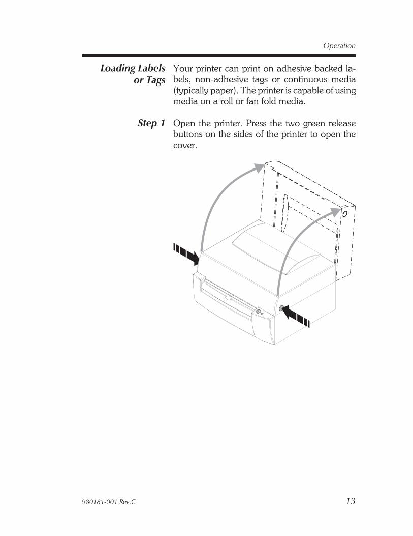
Loading Labelsor Tags
Your printer can print on adhesive backed la-bels, non-adhesive tags or continuous media(typically paper). The printer is capable of usingmedia on a roll or fan fold media.
Step 1 Open the printer. Press the two green releasebuttons on the sides of the printer to open thecover.
980181-001 Rev.C 13
Operation
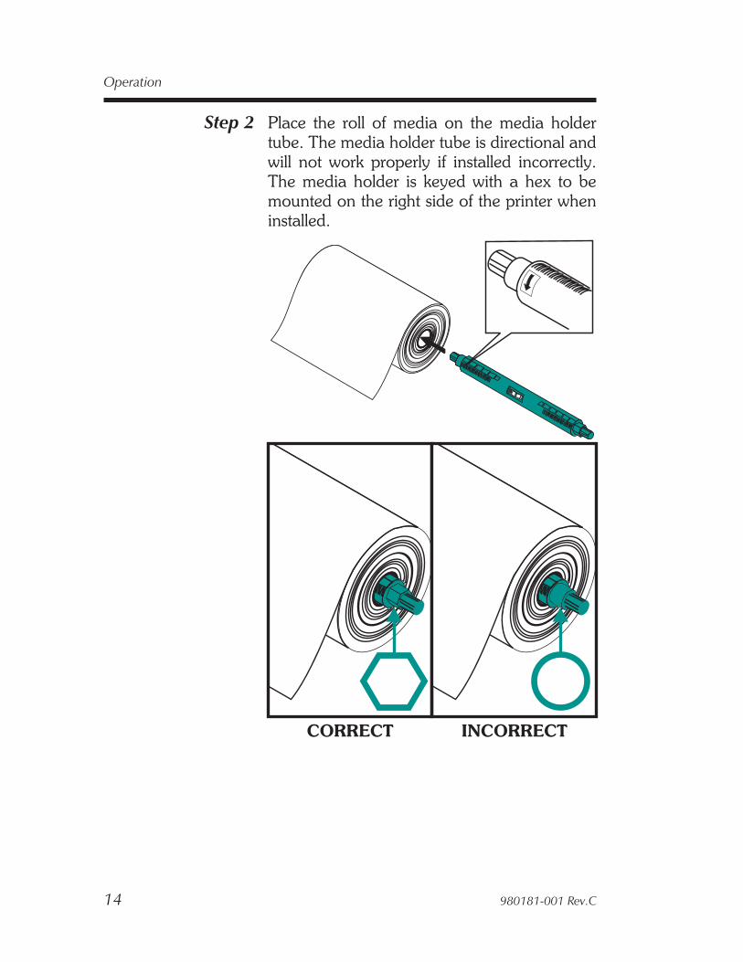
Step 2 Place the roll of media on the media holdertube. The media holder tube is directional andwill not work properly if installed incorrectly.The media holder is keyed with a hex to bemounted on the right side of the printer wheninstalled.
14 980181-001 Rev.C
Operation
CORRECT INCORRECT
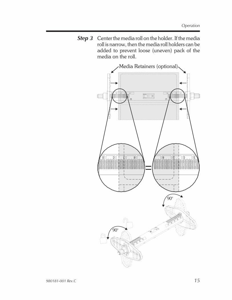
Step 3 Center the media roll on the holder. If the mediaroll is narrow, then the media roll holders can beadded to prevent loose (uneven) pack of themedia on the roll.
980181-001 Rev.C 15
Operation
Media Retainers (optional)
90°
90°
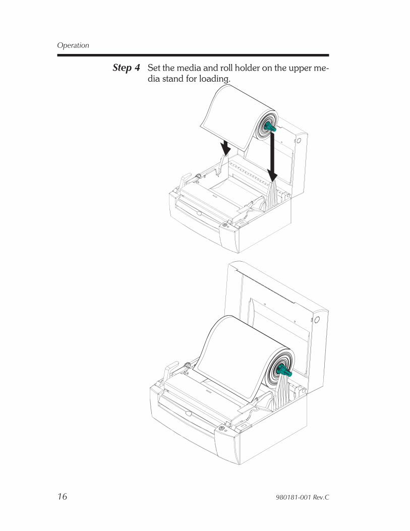
Step 4 Set the media and roll holder on the upper me-dia stand for loading.
16 980181-001 Rev.C
Operation

Step 5 Turn the media guide adjustment wheel to-wards the rear of the printer to open the mediaguides.
Open the media guides until they are wider thanthe media.
980181-001 Rev.C 17
Operation
MediaGuides

Step 6 Open the print head carriage with the releaselever. Pull forward and then up.
18 980181-001 Rev.C
Operation
Release Lever
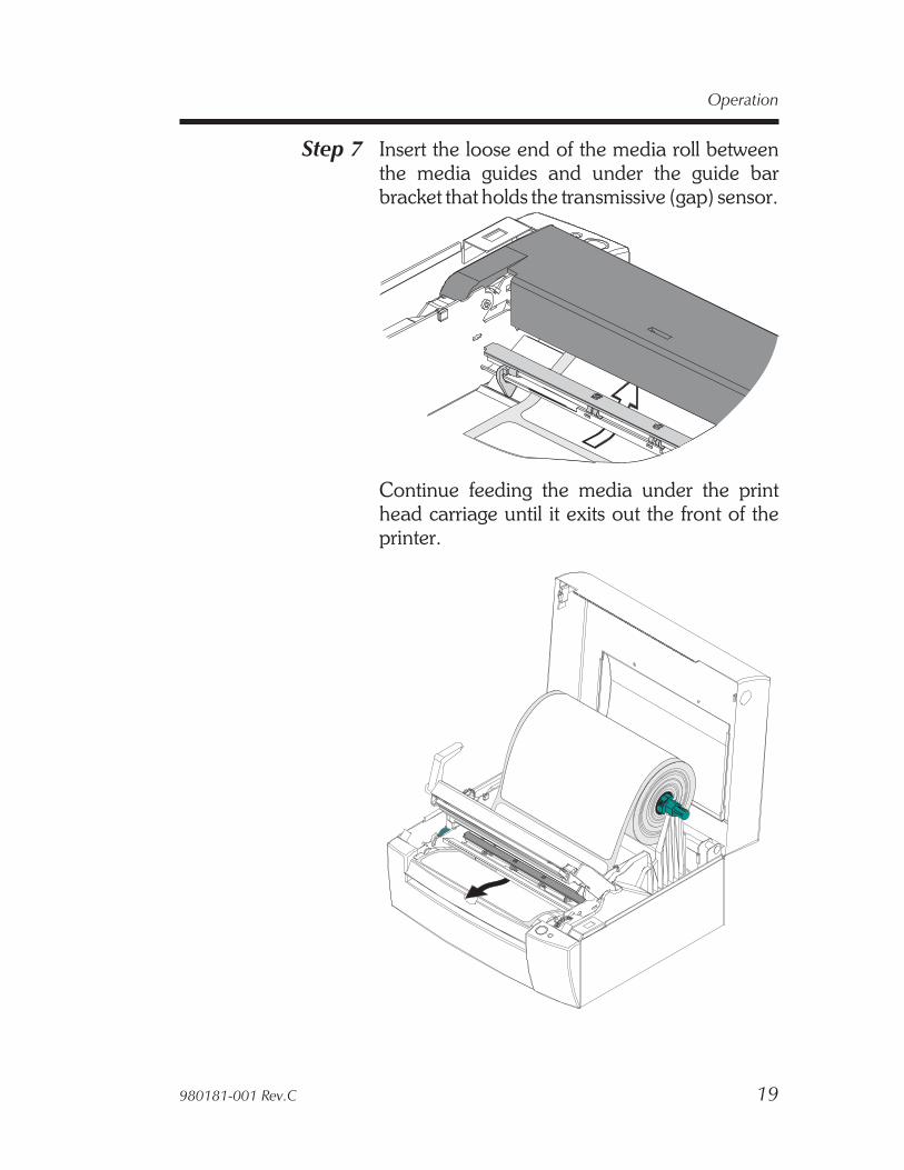
Step 7 Insert the loose end of the media roll betweenthe media guides and under the guide barbracket that holds the transmissive (gap) sensor.
Continue feeding the media under the printhead carriage until it exits out the front of theprinter.
980181-001 Rev.C 19
Operation
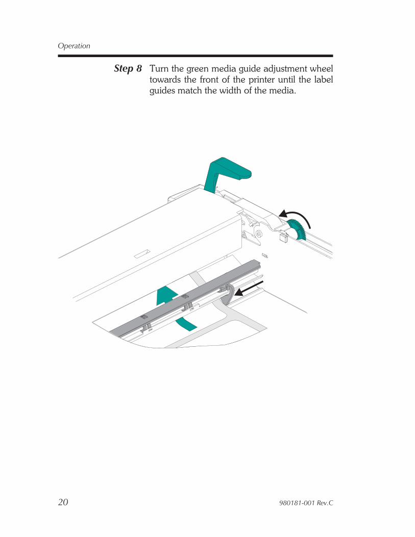
Step 8 Turn the green media guide adjustment wheeltowards the front of the printer until the labelguides match the width of the media.
20 980181-001 Rev.C
Operation

Step 9 Move the media roll to the lower media standfor printing.
980181-001 Rev.C 21
Operation
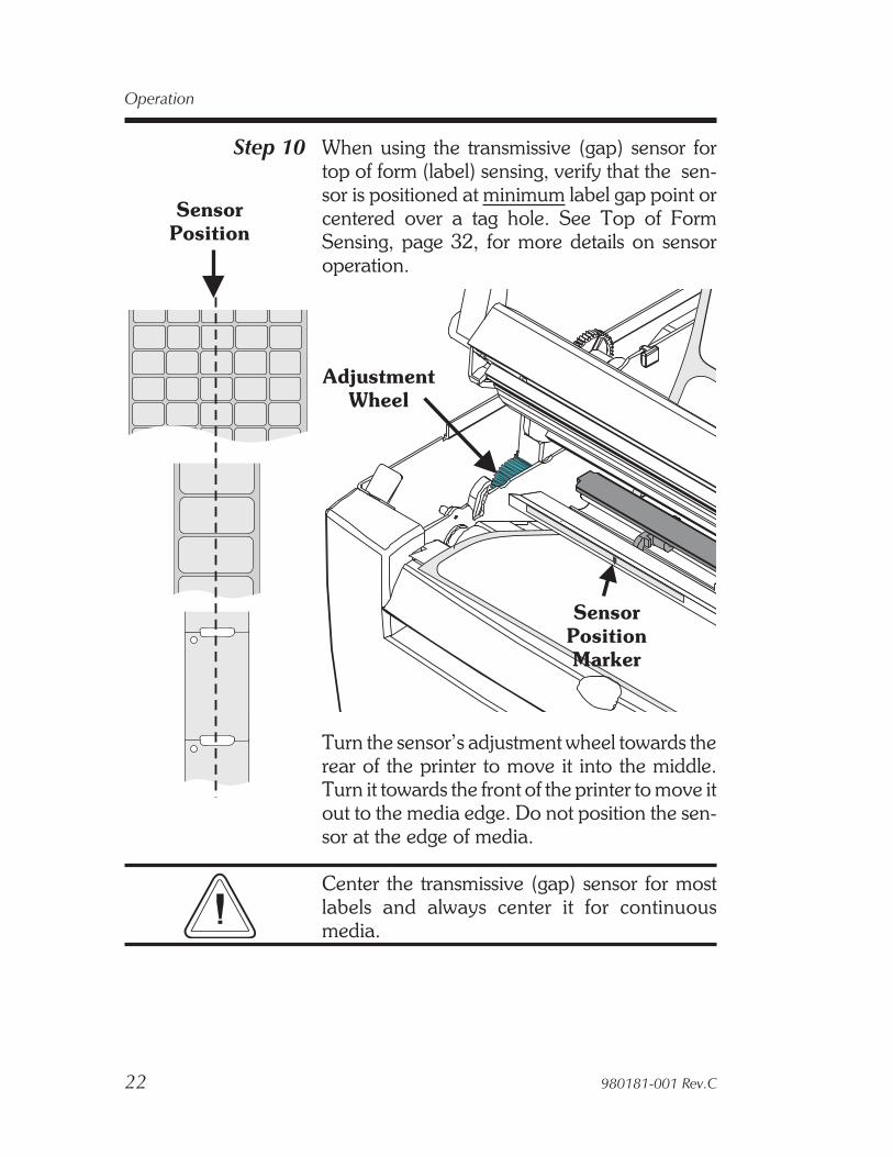
Step 10 When using the transmissive (gap) sensor fortop of form (label) sensing, verify that the sen-sor is positioned at minimum label gap point orcentered over a tag hole. See Top of FormSensing, page 32, for more details on sensoroperation.
Turn the sensor’s adjustment wheel towards therear of the printer to move it into the middle.Turn it towards the front of the printer to move itout to the media edge. Do not position the sen-sor at the edge of media.
Center the transmissive (gap) sensor for mostlabels and always center it for continuousmedia.
22 980181-001 Rev.C
Operation
AdjustmentWheel
SensorPositionMarker
SensorPosition

Step 11 Close and lock the print head carriage. Push theprint head carriage down to close and then pushthe lever back to lock.
Turn on the printer power. Tap the FEED con-trol until the STATUS indicator glows GREEN.
980181-001 Rev.C 23
Operation
Step 12 Set label detection parameters for media:
• Use the AutoSense procedure for first timeuse of new media to set the transmissive(gap) sensor.
• Use the AutoSense procedure for detectionof label and gap lengths.
• Use EPL2 programming (Q) command toset form length (and gap) as well as media de-tection and control method for sensing labelgap, black mark or continuous (unmarked)media.
Windows Users!Use Settings / Printers on the Start Menu ofWindows 95 or Windows NT versions 3.51 &4.0 to select the label size that matches the labelsloaded in the printer.
24 980181-001 Rev.C
Operation

Loading TransferRibbons
Transfer ribbons are used when printing onthermal transfer media such as adhesive labelsor non-adhesive tags. Thermal transfer ribbonsare available in general purpose wax (blueleader), general purpose wax-resin (silverleader) and polyester resin (gold leader).
The print head carriage in a thermal transferprinter includes these functional features:• Ribbon Take-Up Spindles (forward pair)
Pulls ribbon over the print head.
• Ribbon Supply Spindles (back pair)Provides back tension to stop wrinkles.
• Ribbon Tracking Bar (in back of print headcarriage). Automatically tracks ribbon ten-sion (equalizes) across the ribbon’s width.
980181-001 Rev.C 25
Operation
Take-UpSpindles
SupplySpindles
TrackingBar
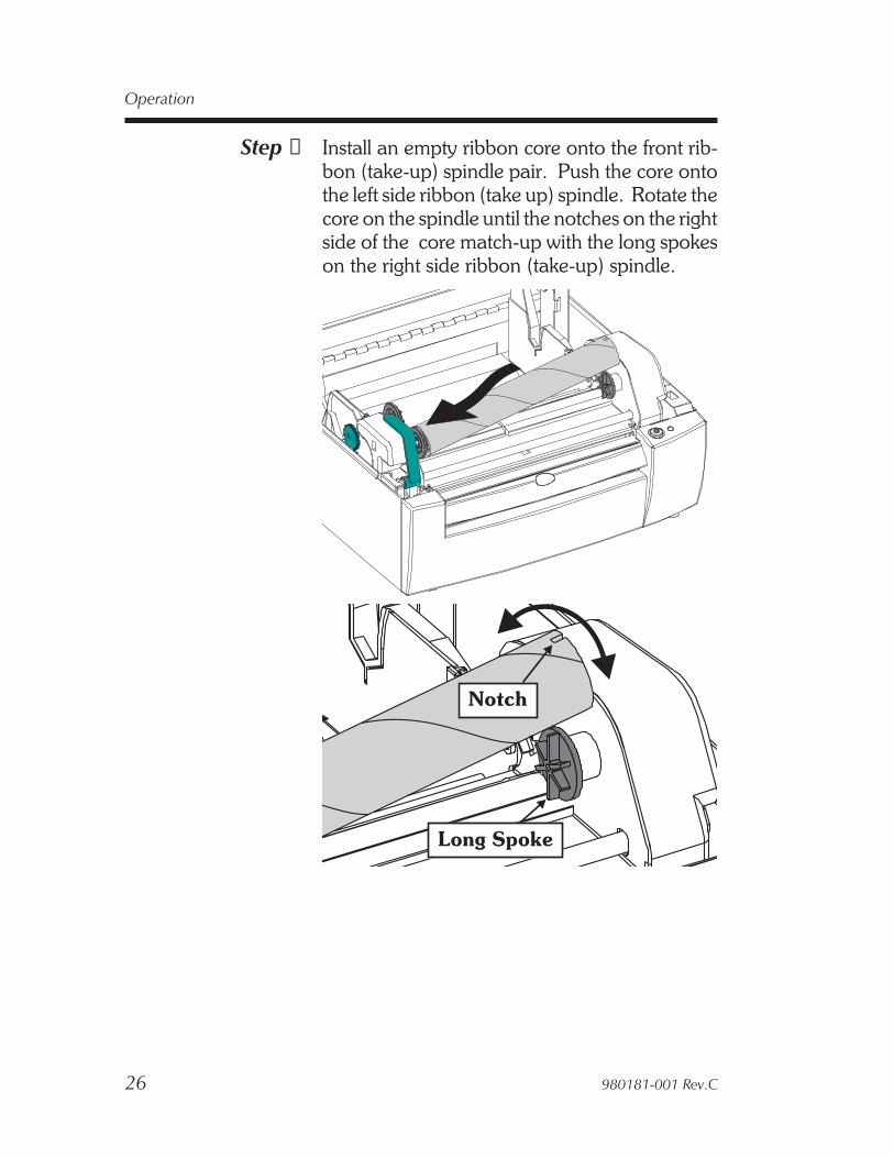
Step ➊ Install an empty ribbon core onto the front rib-bon (take-up) spindle pair. Push the core ontothe left side ribbon (take up) spindle. Rotate thecore on the spindle until the notches on the rightside of the core match-up with the long spokeson the right side ribbon (take-up) spindle.
26 980181-001 Rev.C
Operation
Long Spoke
Notch
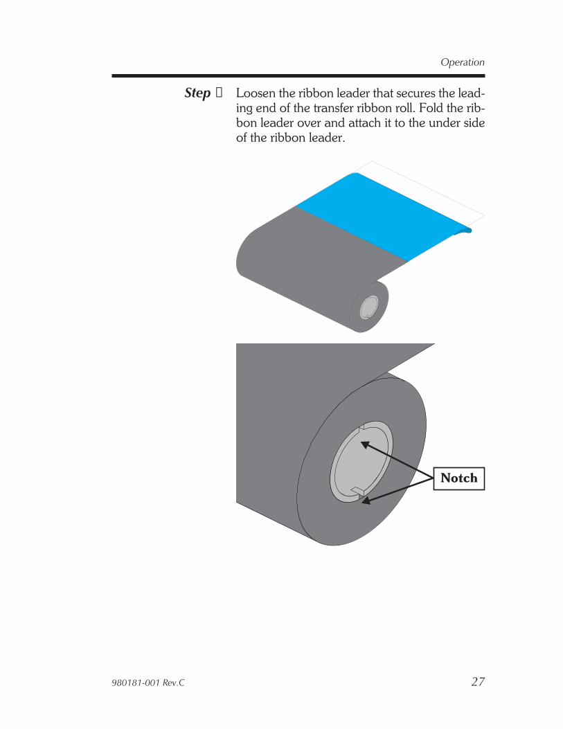
Step ➋ Loosen the ribbon leader that secures the lead-ing end of the transfer ribbon roll. Fold the rib-bon leader over and attach it to the under sideof the ribbon leader.
980181-001 Rev.C 27
Operation
Notch
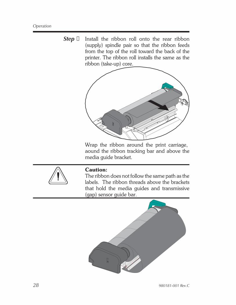
Step ➌ Install the ribbon roll onto the rear ribbon(supply) spindle pair so that the ribbon feedsfrom the top of the roll toward the back of theprinter. The ribbon roll installs the same as theribbon (take-up) core.
Wrap the ribbon around the print carriage,aound the ribbon tracking bar and above themedia guide bracket.
Caution:The ribbon does not follow the same path as thelabels. The ribbon threads above the bracketsthat hold the media guides and transmissive(gap) sensor guide bar.
28 980181-001 Rev.C
Operation

Step ➍ Hold open the print carriage to pull the ribbonthrough towards the front of the print carriageand up to the empty take-up core. Center theribbon on ribbon core. Attach the ribbon to thecore with the adhesive strip on the leader orwith tape.
980181-001 Rev.C 29
Operation

Step ➎ Rotate the ribbon take-up core a minimum onefull revolution (from the top to the back of theprinter) to remove most of the slack from the rib-bon. Verify that the ribbon is wrapping straighton the ribbon core.
After the media is loaded, hold the ribbon snugand close the print head. See label and tag (me-dia) loading, page 13.
Press the FEED button (with the printer poweron) to condition the ribbon. This is to removethe slack and wrinkles in the ribbon. Repeat un-til the slack is removed. Verify that the ribbon iswrapping straight on the ribbon core.
30 980181-001 Rev.C
Operation
Removing APartially Used
Transfer Ribbon
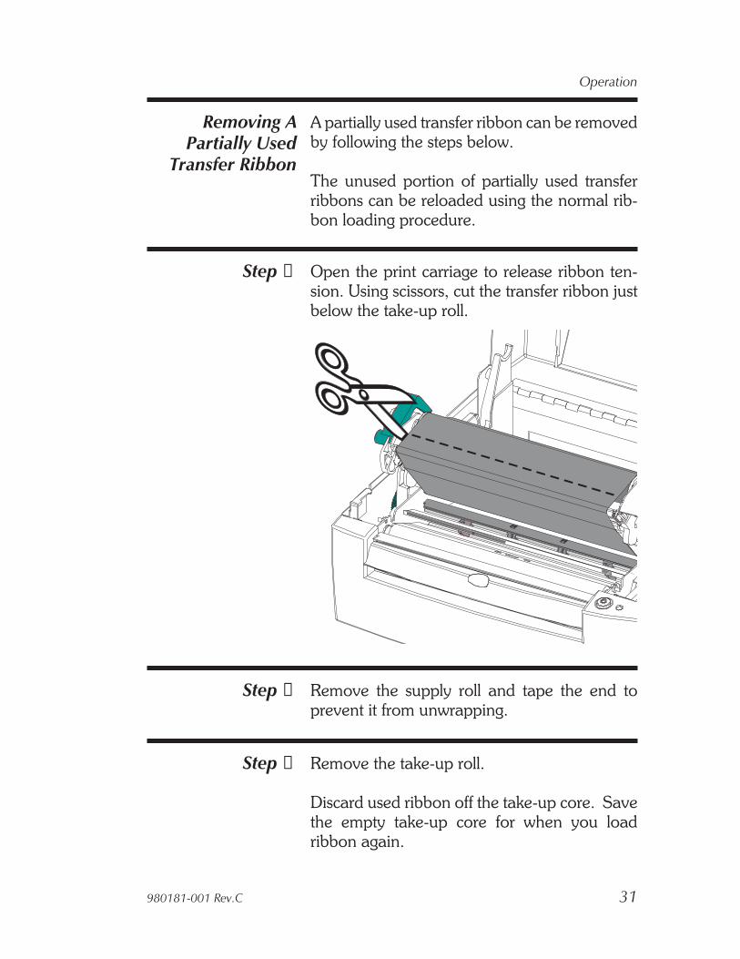
A partially used transfer ribbon can be removedby following the steps below.
The unused portion of partially used transferribbons can be reloaded using the normal rib-bon loading procedure.
Step ➊ Open the print carriage to release ribbon ten-sion. Using scissors, cut the transfer ribbon justbelow the take-up roll.
Step ➋ Remove the supply roll and tape the end toprevent it from unwrapping.
Step ➌ Remove the take-up roll.
Discard used ribbon off the take-up core. Savethe empty take-up core for when you loadribbon again.
980181-001 Rev.C 31
Operation
Top Of FormSensing
To accommodate different media and mediadimensions, your printer is equipped with sen-sors capable of detecting the top of form for la-bels or tags. Two methods are used by theprinter for top of form sensing: gap sensing andblack mark sensing.
Gap Sensing The gap sensing feature depends on the abilityof the movable transmissive (gap) sensor to“see through” the label liner between labels.Label and label backing liner opacity vary dueto manufacturing differences in label stock. Thesensor may have difficulty distinguishing thedifference between labels and the liner and mayrequire the user to AutoSense the media. Gapsensing is standard on all printers and the sensi-tivity is set with the AutoSense feature.
Black MarkSensing
The black mark sensing feature depends on theprinter’s fixed position, reflective (black mark)sensor. The sensor is in the middle of the mediapath. The black mark sensor is used with speciallabels that have a black mark printed on the backof the label liner or tag between each label or tag.Black mark sensing is standard on all printers.
Continuous Media If the media is continuous (fax or plain paper)with no marks notches or gaps, then the top ofform and form length must be set by program-ming. The transmissive sensor senses mediaout. For proper operation, the printer needs tomeasure the length of the form.
See the Q command in the EPL2 programmingmanual for setting the form length of continuousmedia with no label gaps, black line mark ornotch hole.
32 980181-001 Rev.C
Operation

Using AutoSense The AutoSense feature sets sensitivity of thetransmissive sensor and measures and storesthe form (label) and gap lengths. To activate theAutoSense feature:
Step 1 Set the power switch to the OFF (0) position.
Step 2 Load labels into the printer (do not use the dis-penser).
Step 3 Press and hold the FEED Control button whileplacing the power switch in the ON (1) position.The STATUS Indicator light will blink. Releasethe FEED Control when the printer starts feed-ing labels and the indicator turns solid green. Donot hold the FEED Control button more than 5seconds.
The printer will advance 3-4 labels while per-forming the adjustment. When the adjustmentis complete, a status summary label will beprinted and the printer will be placed in Diag-nostic Dump mode.
Dump ModeSample Printout
980181-001 Rev.C 33
Operation

Step 4 Tap the FEED Control once to switch the printerback to normal operation.
If the indicator light turns AMBER or RED, referto Appendix A for troubleshooting information.
34 980181-001 Rev.C
Operation
Cleaning YourPrinter
You have easy access to all of the printer’s me-dia path areas to allow for cleaning and clearingof media jams. You can clean the sensor areas,print head, platen roller and areas adjacent tothe media path surfaces.
Warning -Shock Hazard - See page vi.Always turn the printer off before cleaning.
Warnung - Elektrische Gefahr - Zuerstabschalten dur Drucker. Säubern Sie jetzt denDrucker.
Use a brush or vacuum to clean the media path(except the print head). If necessary, use alint-free cloth very lightly moistened with waterto clean the platen. Let the platen dry beforeloading labels.
Warning - Static Discharge - See page vi.Never touch the print head. Always clean theprint head with a cleaning pen (to protect theprint head from static discharge and fibers).
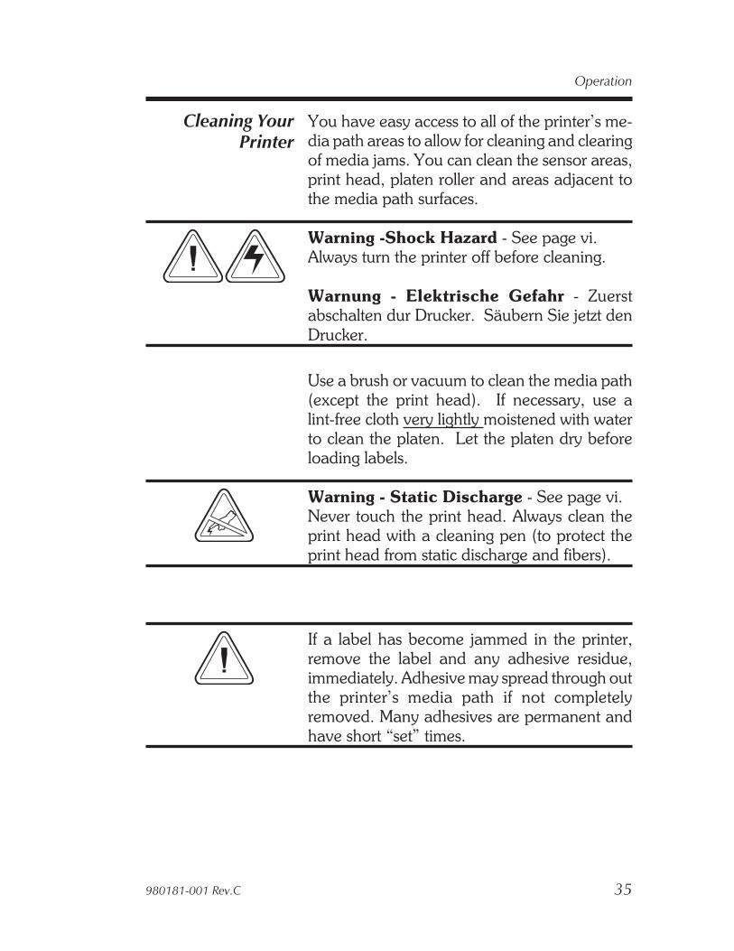
If a label has become jammed in the printer,remove the label and any adhesive residue,immediately. Adhesive may spread through outthe printer’s media path if not completelyremoved. Many adhesives are permanent andhave short “set” times.
980181-001 Rev.C 35
Operation
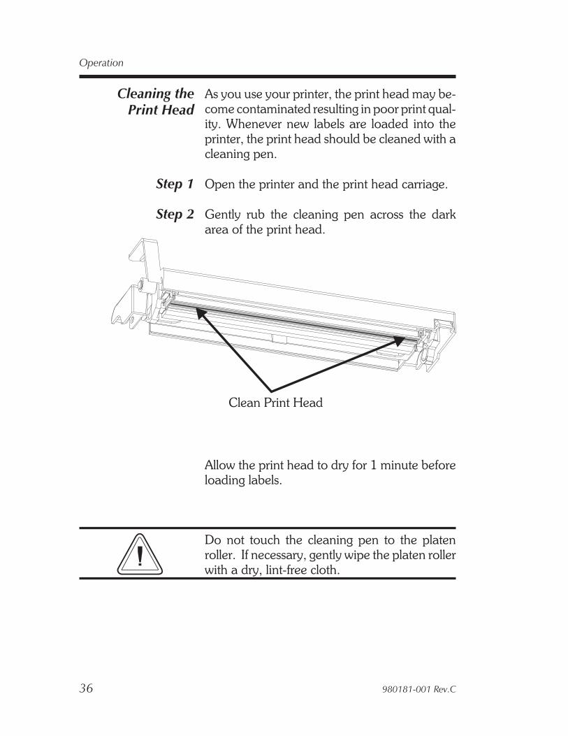
Cleaning thePrint Head
As you use your printer, the print head may be-come contaminated resulting in poor print qual-ity. Whenever new labels are loaded into theprinter, the print head should be cleaned with acleaning pen.
Step 1 Open the printer and the print head carriage.
Step 2 Gently rub the cleaning pen across the darkarea of the print head.
Allow the print head to dry for 1 minute beforeloading labels.
Do not touch the cleaning pen to the platenroller. If necessary, gently wipe the platen rollerwith a dry, lint-free cloth.
36 980181-001 Rev.C
Operation
Clean Print Head

Cleaning Underthe Sensor Bracket
The transmissive (gap) sensor guide bar bracketcan pivot up for easy cleaning.
Step 1 Open the print head carriage.
Step 2 Open the sensor bracket. Pull the slide lock tothe left and lift the front of the bracket up.
Step 3 Clean the metal part of the bracket, only. Thesensor is recessed to protect it from labels andadhesive.
Clean the clear sensor window below the sensorbracket. Do not use abrasive cleaning materials.Only use water on a lint free, clean, damp clothvery lightly moistened. Let dry. Verify that thewindow is clear of streaks and clouding.
Step 4 Swing the sensor bracket down to close. Theslide lock will automatically lock when in posi-tion.
Close the print carriage.
980181-001 Rev.C 37
Operation
Transmissive (Gap)Sensor Bracket Slide Lock
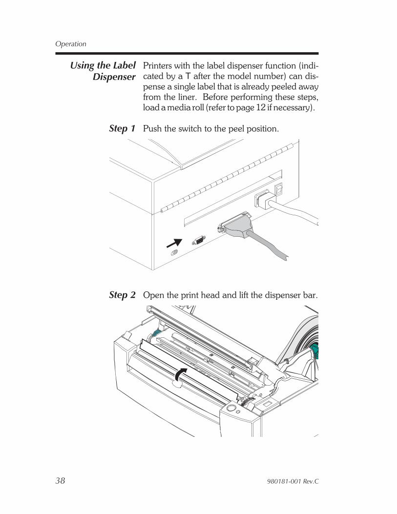
Using the LabelDispenser
Printers with the label dispenser function (indi-cated by a T after the model number) can dis-pense a single label that is already peeled awayfrom the liner. Before performing these steps,load a media roll (refer to page 12 if necessary).
Step 1 Push the switch to the peel position.
Step 2 Open the print head and lift the dispenser bar.
38 980181-001 Rev.C
Operation
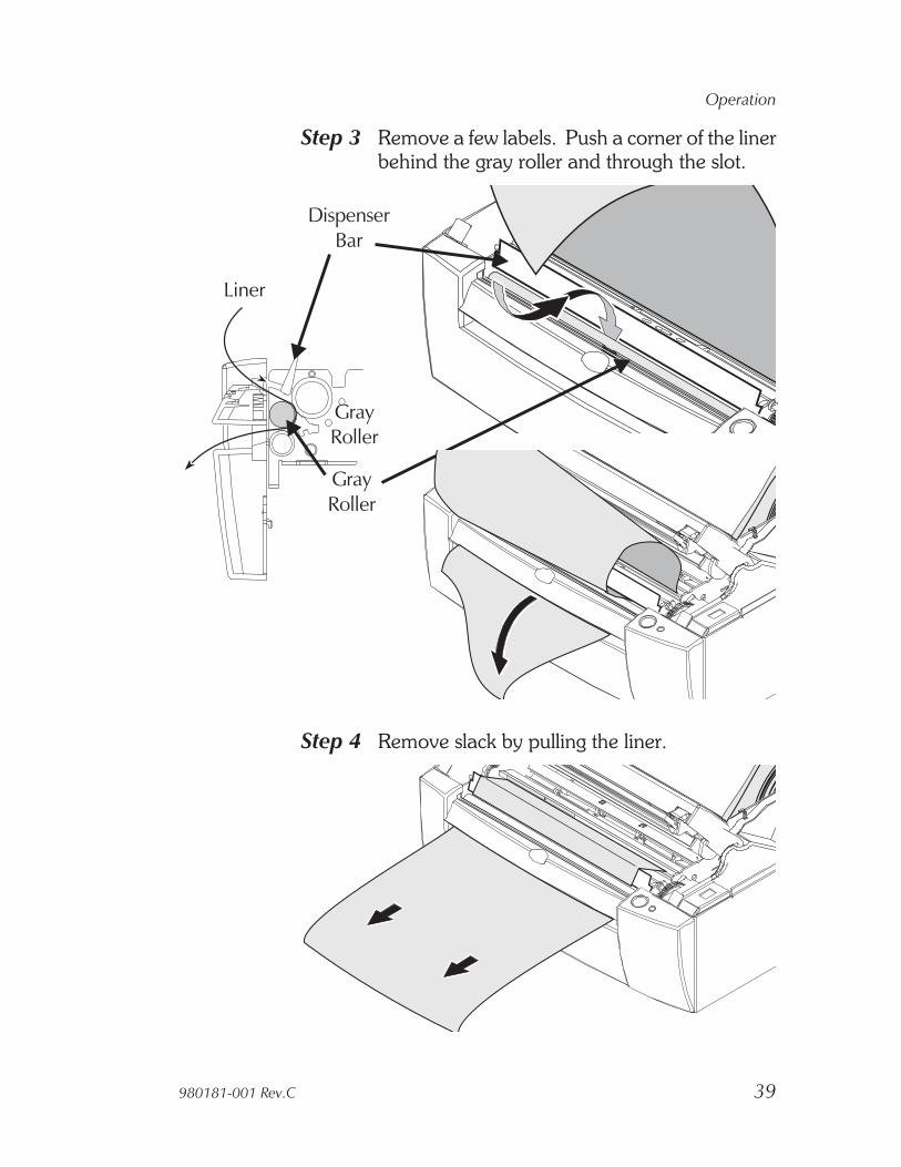
Step 3 Remove a few labels. Push a corner of the linerbehind the gray roller and through the slot.
Step 4 Remove slack by pulling the liner.
980181-001 Rev.C 39
Operation
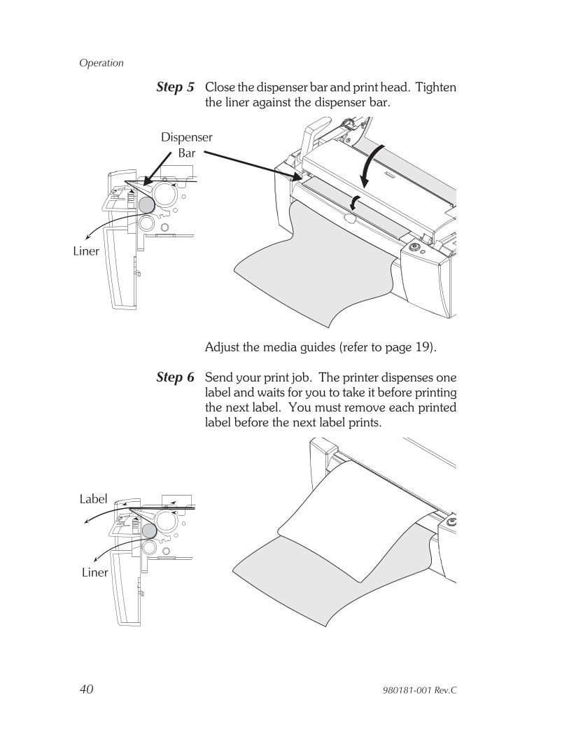
Step 5 Close the dispenser bar and print head. Tightenthe liner against the dispenser bar.
Adjust the media guides (refer to page 19).
Step 6 Send your print job. The printer dispenses onelabel and waits for you to take it before printingthe next label. You must remove each printedlabel before the next label prints.
40 980181-001 Rev.C
Operation

Appendix ATroubleshooting
This section addresses the most common issuesyou may face with operation and configurationof the printer.
Where to Start The first troubleshooting reference source is theCommon Problems Troubleshooting table onthe following page.
980181-001 Rev.C 41
Troubleshooting

Common Printing ProblemsTroubleshooting Guide
Problem Solution or Reason
STATUS indicatordoes not light GREENwhen power switch isturned to the ON (1)position.
1. Check power connections from the printer tothe outlet.
With the STATUSindicator light GREEN,the printer appears tobe working, butnothing is printed.
1. Verify that the labels are the correct type.2. Check the roll and verify that the print surface
faces up for (direct thermal) printing.3. Check that the transfer ribbon is correctly
routed and has the ink side out (TLP only).
Printing is faded orpoor quality.
1. Clean the print head with cleaning pen.2. Adjust print speed/darkness in software or
with programming.3. Check the roll and verify that the media print
surface is facing up.4. Verify that the correct combination thermal
transfer ribbon and media are in use.
Printing stops and theSTATUS indicatorlights RED.
1. Possible problem sensing labels with transmis-sive (gap) sensor. Perform AutoSense adjust-ment. Align the transmissive (gap) sensorposition, see page 22.
2. Possible problem with label media.a) Gap between the bottom of a label and thetop of the next label should be at least 1/16".b) For tags, see Tag Media Sensing, page 46.c) Use only Eltron approved labels and tags.
3. Possible label jam.4. Check that the media is correctly routed.5. Possible software/programming problem.
a) Check the printer memory configuration.b) Refer to the EPL2 Programming manualfor the correct data syntax.
6. Transmissive sensor is dirty. Clean mediapath.
42 980181-001 Rev.C
Troubleshooting
Problem Solution or Reason
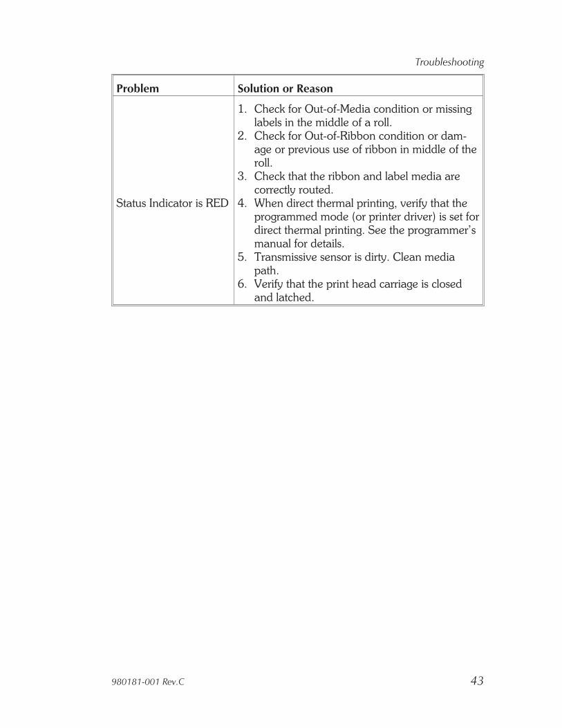
Status Indicator is RED
1. Check for Out-of-Media condition or missinglabels in the middle of a roll.
2. Check for Out-of-Ribbon condition or dam-age or previous use of ribbon in middle of theroll.
3. Check that the ribbon and label media arecorrectly routed.
4. When direct thermal printing, verify that theprogrammed mode (or printer driver) is set fordirect thermal printing. See the programmer’smanual for details.
5. Transmissive sensor is dirty. Clean mediapath.
6. Verify that the print head carriage is closedand latched.
980181-001 Rev.C 43
Troubleshooting
Other SupportResources
The first troubleshooting reference source is thetable on the previous page. Next, contact thedealer where you purchased your printer.
Zebra Technologies also provides a variety ofinformation and user support services:• Internet:
Web Address: http://www.eltron.comftp: //ftp.eltron.come-mail:Label Printers: [email protected] Printers: [email protected]: [email protected]: [email protected] America: [email protected]
• CompuServe e-mail: 102251,1164
• Customer Service: +1 (805) 579 1800For the name of a dealer in your area.
• Technical Support FAX:USA: +1 (805) 579 1808Asia: +65 84 20 366Northern Europe: +44 (0) 1189 895 762Southern Europe: +33 (0) 240 097 070Latin America: +1 (847) 584 2725For your assistance and support with Eltronprinters and software.
44 980181-001 Rev.C
Troubleshooting

Serial InterfaceCommunication
Configuration
The printer’s serial port is configured with theY command for the printer. See the EPL2 pro-grammer's manual for details.
The printer’s serial port default configuration is:9600 baud8 bit data1 stop bitNo parity
Serial InterfaceCable Wiring
The figure below displays the cable wiring re-quired to use the printer’s serial interface
980181-001 Rev.C 45
Troubleshooting
N/CRxDTxDDTRGNDDSRRTS
RICTS
PrinterHost112233445566778899
DB-9Pin #
DB-9Pin #
Female DB-9 to Male DB-9
N/CRxDTxDDTRGNDDSRRTS
RICTS
PrinterHost18233242057667485922
DB-25Pin #
DB-9Pin #
Female DB-25 to Male DB-9*+5 volts at 150 mA for external device (e.g. KDU or scanner)
+5 Volts*TxDRxDN/CGNDRDYN/C
N/CRDY
+5 Volts*TxDRxDN/CGNDRDYN/C
N/CRDY
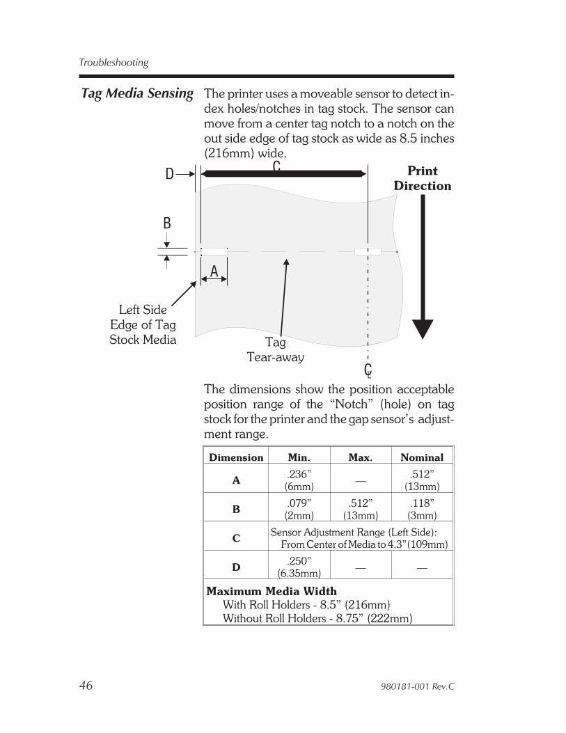
Tag Media Sensing The printer uses a moveable sensor to detect in-dex holes/notches in tag stock. The sensor canmove from a center tag notch to a notch on theout side edge of tag stock as wide as 8.5 inches(216mm) wide.
The dimensions show the position acceptableposition range of the “Notch” (hole) on tagstock for the printer and the gap sensor’s adjust-ment range.
Dimension Min. Max. Nominal
A .236”(6mm) — .512”
(13mm)
B .079”(2mm)
.512”(13mm)
.118”(3mm)
C Sensor Adjustment Range (Left Side):From Center of Media to 4.3”(109mm)
D .250”(6.35mm) — —
Maximum Media WidthWith Roll Holders - 8.5” (216mm)Without Roll Holders - 8.75” (222mm)
46 980181-001 Rev.C
Troubleshooting
B
D C
A
CL
Left SideEdge of TagStock Media Tag
Tear-away
PrintDirection

Appendix BPrinter Features
Features The printer has many time saving, user friendly,design features. Some of these printer featuresare listed below:
• Anti-jam, straight through media path
• Sturdy, clam shell case with force balancedlid and locking latch for safer handling
• Internal label roll holder
• 5 printer resident fonts
• Over 20 bar codes, including 2 dimensionalbar codes PDF-417 and MaxiCode
• Batch or on-demand printer operation
• Double buffered label formatting for “on-the-fly” label printing
• Power media loading
• Flip-up print head carriage and label sensorassemblies for fast, easy cleaning.
• Center aligned label printing and adjustment.
• RS232C serial and Centronics parallel ports
980181-001 Rev.C 47
Printer Features
• Flash memory makes firmware updates easyand seamless
• Create-A-Label Tools for Windows®
Software
• Windows Drivers (Windows® 3.1X,Windows® 95, and Windows® NT 3.51 &4.0)
• Snap’N’Lock front bezel for easy access
Firmware Options • Flash memory expandable to 1 megabyte.
• SRAM memory expandable to 1 megabyte.
• Real Time and Date Clock
• Asian character sets(Chinese, Japanese or Korean).
Hardware Options • Factory installed Dispenser with label presen-tation sensor.
• Factory installed label and tag Cutter.
Accessories • Keyboard Display Unit (KDU) for astand alone printing solution.
• TwinAX Converter
• Create-A-Label 3 for Windows
GeneralSpecifications
• 512KB Flash and 512KB SRAM standard
• Downloadable firmware capability
• Moveable see-through and center justifiedblack mark sensor for die-cut labels and tags
• AutoSense automatic label sensor adjust-ment
• Internal label roll holder
• Rear-feed slot for fan-fold or roll label stock
48 980181-001 Rev.C
Printer Features

• Easy-to-load label and ribbon path
• Easy-to-use EPL2 command language
• Prints text, graphics and bar codes in four di-rections: 0°, 90°, 80° and 270°
• Graphics, line and box drawing features,PCX bit map supported
• Label back feed for maximum label usageprinting
• Diagnostics and configuration print out andASCII dump
• Double buffering for faster throughput
Software andDrivers
• Create-A-Label Tools for Windows™
• Drivers available for Windows 3.xx™, Win-dows 95™, NT 3.51 and NT 4.0
Printing • Direct thermal (LP) and thermal transfer(TLP) printing
• Maximum print speed 4" (102mm) persecond
• 203 dpi (8 dots/mm) print resolution
• Maximum print width 8.5" (216mm)
• Maximum print length 11" (A4) standard, 22"(2 x A4) optional
• Minimum print length .5" (12.7mm)With optional cutter 1.25” (31.75mm)
Bar Codes • Code 39
• Code 93
• Code 128 UCC (Serial Shipping ContainerCode)
980181-001 Rev.C 49
Printer Features

• Code 128 Autoselect
• CodaBar
• UCC/EAN-128
• Interleaved 2 of 5
• UPC-A, UPC-E, 2 & 5 digit add on
• EAN-8, EAN-13, 2 & 5 digit add on
• POSTNET
• MaxiCode
• PDF-417
• German Postal Code
• Bar codes with or without human readabletext
• Bar codes can be printed in four directions 0°,90°, 180° and 270°
Standard Fonts • International character sets standard
• Five alpha-numeric fonts from .049"(1.25mm) to .23" (5.84mm) high
• All fonts expandable vertically and horizon-tally up to 8x
• Fonts can be printed in four directions 0°,90°, 180° and 270°
• Smooth soft fonts can be downloaded fromCreate-A-Label Tools for Windows™ andCreate-A-Label 3 for Windows™
Media Sensing • Moveable see-through sensor for die-cut la-bels and tags
• Reflective sensor for use with black stripemarks
50 980181-001 Rev.C
Printer Features

Media • Type: roll-fed, die-cut, continuous or fan-fold labels, tags or tickets
• Materials: thermal transfer or thermal sensi-tive papers
• Maximum media width: 8.75" (222.3mm)
• Minimum media width: 4" (102mm)
• Maximum media length: 11" (279mm) stan-dard, 22" (559mm) optional with maximumprint width set. Note: The actual print lengthis dependent upon the programmed print(image) width and the maximum length willincrease as the print area is narrowed.
• Minimum media length: .5" (12.7mm)With optional cutter: 1.25” (31.75mm)
• Media thickness (w/ liner): .003" (.08mm) to.0075" (.19mm)
• Internal supply roll capacity: 5" (127mm)O.D.
Ribbons • Wax, Wax/Resin and Resin
• Standard widths: 4.33" (110mm), 5"(127mm), 6" (152mm), 6.5" (165mm), 7"(178mm) and 8.66" (220mm)
• Standard length: 6.142" (156m), on a 1"(25mm) I.D. Core
CommunicationsInterface
• RS232C
• Centronics parallel
• Xon/Xoff, hardware handshaking
• Programmable 7 or 8 bit data length, 1 or 2stop bits, selectable parity
• 4,800 to 38,400 baud rates
980181-001 Rev.C 51
Printer Features

Mechanical • Width: 13.6" (344mm)
• Depth: 11.9" (305mm)
• Height: 8.1" (204mm)
• Weight: 21.0lbs. (9.5kg)
Electrical • Voltage: 115V/60 Hz, 230V/50 Hz
• Complies with FCC Class B and CE require-ments; Built to UL, CUL and TUV require-ments.
Environmental • Operating temperature: 40°F to 104°F (5°Cto 40°C)
• Storage Temperature: -40°F to 140°F (-40°Cto 60°C)
• Operating Humidity: 10% to 80% non-condensing
• Storage Humidity: 10% to 90% non-condensing
• Ventilation: Free air
52 980181-001 Rev.C
Printer Features

Appendix CSupplies and Accessories
Accessories available for the Strata™ printer arelisted below. Always refer to the ELTRON partnumber when placing an order. For the nameof an Eltron brand dealer in your area, call:1(800) 344-4003 or the nearest Zebra Technol-ogies office (located on the back of thismanual).
Description Part Number
Parallel Interface Cable, 6’Parallel Interface Cable, 10’Serial Interface Cable, 6’ (DB-9 to DB-9)Serial Interface Cable, 10’ (DB-9 to DB-9)Serial Interface Cable, 6’ (DB-25 to DB-9)
300016-006300016-010300017-006300017-010300018-006
KDU (Keyboard Display Unit) 120180-001
Windows Printer DriverCreate-A-Label 3 for Windows
105501-003105524-001
User’s Manual (this Manual)Programmer’s Manual
980181-001980009-001
980181-001 Rev.C 53
Supplies and Accessories

54 980181-001 Rev.C
Supplies and Accessories
Featu
res
Low
cos
tEa
se o
f use
Low
Env
ironm
enta
l Dur
abili
tyLi
mite
d La
bel L
ifeW
ill fa
de a
nd/o
r di
scol
or w
hen
expo
sed
to h
eat,
sunl
ight
, and
chem
ical
s.
Low
est c
ost t
herm
al tr
ansf
erco
mbi
natio
nM
ost c
omm
only
use
dLo
w e
nviro
nmen
tal d
urab
ility
Low
abr
asio
n re
sist
ance
Long
er li
fe th
an d
irect
ther
mal
Rib
bon
Not
Use
d
Wax
Med
ia (
Stock
)
Pape
r La
bel
Tag
Synt
hetic
Lab
el
Pape
r La
bel
Tag
Typ
ical A
pp
licatio
ns
Ship
ping
Inve
ntor
y Tr
acki
ng
Ship
ping
Inve
ntor
y Tr
acki
ngPr
oduc
t Lab
elin
gC
ompl
ianc
e La
belin
g
Direct Thermal Thermal Transfer

980181-001 Rev.C 55
Supplies and Accessories
Featu
res
Bette
r en
viro
nmen
tal d
urab
ility.
Bette
r ab
rasi
on r
esis
tanc
e th
anw
axM
ore
expe
nsiv
e th
an w
axG
ood
aest
hetic
app
eara
nce
Hig
h en
viro
nmen
tal d
urab
ility
Hig
h ph
ysic
al d
urab
ility
Exce
llent
aes
thet
ic a
ppea
ranc
eM
ost e
xpen
sive
labe
l/ta
gco
mbi
natio
n
Rib
bon
Gen
eral
Purp
ose
Resi
n
Har
d Re
sin
Med
ia (
Stock
)
Pape
r La
bel
Tag
Synt
hetic
Lab
el
Synt
hetic
Lab
el
Typ
ical A
pp
licatio
ns
Reta
il ap
plic
atio
ns w
here
labe
ls a
reha
ndle
dEx
celle
nt fo
r m
ost a
pplic
atio
nsC
ompl
ianc
e La
belin
g
Hig
h te
mpe
ratu
re e
nviro
nmen
tsM
edic
al a
pplic
atio
nsO
utdo
or e
nviro
nmen
tsEn
viro
nmen
ts w
ith c
hem
ical
sC
ompl
ianc
e la
belin
g
Thermal Transfer

56 980181-001 Rev.C
Supplies and Accessories

Appendix DUsing the Media Cutter
Printers with the cutter option have a bezel witha motorized blade. Printers with cutters can dis-pense a single form that is automatically cutfrom the media roll.
980181-001 Rev.C 57
Guidelines Use the cutter to cut through continuous paperfrom rolls and liner between labels.
You can switch between cutting and feeding byusing the OC command. You can set formlength and gap distances by using the Q com-mand. Refer to the EPL2 programmer’s man-ual for complete programming information.
Keep the cutter dry. Never use any solutions orsolvents to clean the blade. If there is a jam, fol-low the steps for Clearing the Cutter.
Specifications Cutter warranty 90 days
Blade life 500,000 cuts
Media types Direct thermal paperPaper label linerTag stock
MaximumThickness 0.0075 in. (0.191mm)
Density 150 g/m2
Width 4.00 - 8.75 in.(101.6 - 222.25 mm)
Minimum lengthusing cutter 1.25 in. (31.8 mm)
58 980181-001 Rev.C
Using the Media Cutter
Clearing theCutter
If the media is crooked, a jam can occur. Theonly tool required to clear a jam is a pair of smalltweezers.
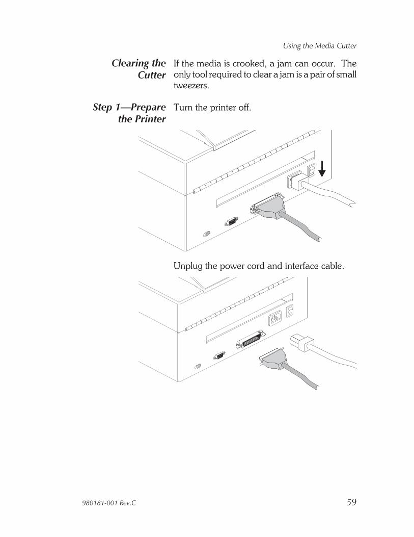
Step 1—Preparethe Printer
Turn the printer off.
Unplug the power cord and interface cable.
980181-001 Rev.C 59
Using the Media Cutter
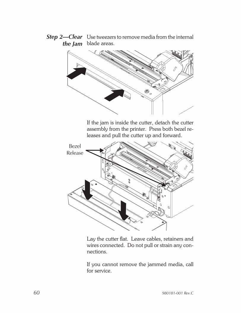
Step 2—Clearthe Jam
Use tweezers to remove media from the internalblade areas.
If the jam is inside the cutter, detach the cutterassembly from the printer. Press both bezel re-leases and pull the cutter up and forward.
Lay the cutter flat. Leave cables, retainers andwires connected. Do not pull or strain any con-nections.
If you cannot remove the jammed media, callfor service.
60 980181-001 Rev.C
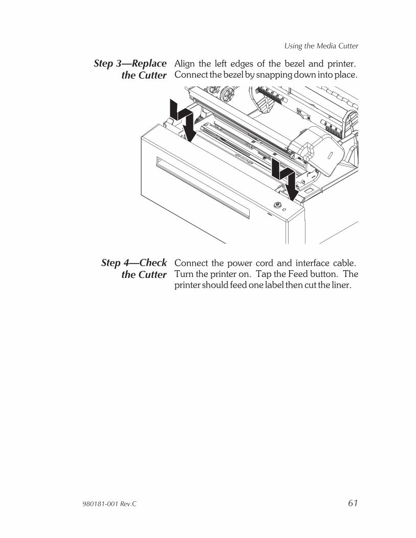
Step 3—Replacethe Cutter
Align the left edges of the bezel and printer.Connect the bezel by snapping down into place.
Step 4—Checkthe Cutter
Connect the power cord and interface cable.Turn the printer on. Tap the Feed button. Theprinter should feed one label then cut the liner.
980181-001 Rev.C 61
Using the Media Cutter

World Wide Offices:
Zebra Technologies CorporationEltron Products1001 Flynn RoadCamarillo, CA 93012-8706 USAPhone: +1 (805) 579 1800
FAX: +1 (805) 579 1808e-mail: [email protected]
Zebra Technologies, EuropeEltron HouseMolly Millars LaneWokingham, RG41 2QZ EnglandPhone: +44 (0) 1189 770 300
FAX: +44 (0) 1189 895 762e-mail: [email protected]
Zebra Technologies, France50 rue Marcel Dassault92100 Boulogne-BillancourtFrancePhone: +33 1 55 20 93 93
FAX: +33 1 55 20 93 99e-mail: [email protected]
Zebra Technologies, Latin America836 Arlington Heights Rd. #357Elk Grove, IL 60007Phone: +1 (847) 584 2714
FAX: +1 (847) 584 2725e-mail: [email protected]
Zebra Technologies, Asia Pacific Headquarters1 Sims Lane #06-11Singapore 387355Phone: +65 84 20 322
FAX: +65 84 20 366e-mail: [email protected]
Products
980181- 001C