99 washington street melrose, ma 02176 pressing … propress® fitting system
TRANSCRIPT

Pressing Tools for Use With: ProPress® Fitting SystemProPress® XL Fitting SystemProPress® XL–C Fitting System
WARNING!Read this Operator’s Manualcarefully before using this tool.Failure to understand and fol-low the contents of this manualmay result in extensive prop-erty damage and/or seriouspersonal injury.
ProPress® Fitting SystemOperator’s Manual
99 Washington Street Melrose, MA 02176 Phone 781-665-1400Toll Free 1-800-517-8431
Visit us at www.TestEquipmentDepot.com

Ridge Tool Companyii
Table of ContentsSafety Symbols..............................................................................................................................................................1
General Safety InformationWork Area Safety........................................................................................................................................................1Electrical Safety ..........................................................................................................................................................1Personal Safety ..........................................................................................................................................................2Tool Use and Care......................................................................................................................................................2Service ........................................................................................................................................................................2
Specific Safety InformationPressing Tool Safety ..................................................................................................................................................2
Description and SpecificationsDescription ..................................................................................................................................................................3Specifications..............................................................................................................................................................3
Inspecting the Press Tool and Attachments ..............................................................................................................5
Tool and Work Area Set-Up
Mounting Attachment Into Press Tool ........................................................................................................................6Calibrating The Pressing Tool For The Specific Pressing Attachment (320-E Pressing Tool Only) ..........................6Calibrating The 320-E With A Jaw Set........................................................................................................................6Calibrating The 320-E With The R2 Actuator (For Use With ProPress XL Rings) ........................................................7Calibrating The 320-E With The V1 Or V2 Actuator (For Use With ProPress Rings Or ProPress XL-C Rings) ........7
Preparing The ConnectionPreparing the Tube ....................................................................................................................................................8Inserting the Tube Into the Fitting ..............................................................................................................................8
Operating InstructionsPressing the Connection with a Ring and Actuator ..................................................................................................10
Inspecting the Press Connection ..............................................................................................................................11
Maintenance Instructions ..........................................................................................................................................12
AccessoriesProPress System For Copper Tubing ......................................................................................................................12
Maintenance Storage ..................................................................................................................................................13
Service and Repair ......................................................................................................................................................13
Clearance Requirements ......................................................................................................................................14-17
Troubleshooting ..........................................................................................................................................................18
Lifetime Warranty ........................................................................................................................................Back Cover
ProPress® Fitting System

Ridge Tool Company 1
ProPress® Fitting System
General Safety Rules*
WARNINGRead all safety warnings and all instructions. Failure tofollow the warnings and instructions may result in electricshock, fire and/or serious injury.
SAVE ALL WARNINGS AND INSTRUCTIONSFOR FUTURE REFERENCE!
The term "power tool" in the warnings refers to yourmains-operated (corded) power tool or battery-operated(cordless) power tool.
Work Area Safety• Keep your work area clean and well lit. Cluttered or
dark areas invite accidents.
• Do not operate power tools in explosive atmo-spheres, such as in the presence of flammableliquids, gases, or dust. Power tools create sparkswhich may ignite the dust or fumes.
• Keep children and by-standers away while oper-ating a power tool. Distractions can cause you to losecontrol.
Electrical Safety
• Power tool plugs must match the outlet. Nevermodify the plug in any way. Do not use any adap-
ter plugs with earthed (grounded) power tools.Unmodified plugs and matching outlets will reducerisk of electric shock.
• Avoid body contact with earthed or grounded sur-faces such as pipes, radiators, ranges and refrig-erators. There is an increased risk of electrical shockif your body is earthed or grounded.
• Do not expose power tools to rain or wet condi-tions. Water entering a power tool will increase the riskof electrical shock.
• Do not abuse the cord. Never use the cord forcarrying, pulling or unplugging the power tool.Keep cord away from heat, oil, sharp edges ormoving parts. Damaged or entangled cords increasethe risk of electric shock.
• When operating a power tool outdoors, use anextension cord suitable for outdoor use. Use of acord suitable for outdoor use reduces the risk of elec-tric shock.
• If operating a power tool in a damp location isunavoidable, use ground fault circuit interrupter(GFCI) protected supply. Use of an GFCI reduces therisk of electric shock.
Personal Safety
• Stay alert, watch what you are doing and use com-
Safety SymbolsIn this operator’s manual and on the product, safety symbols and signal words are used to communicate important safe-ty information. This section is provided to improve understanding of these signal words and symbols.
This is the safety alert symbol. It is used to alert you to potential personal injury hazards. Obey all safety messages that follow thissymbol to avoid possible injury or death.
DANGER indicates a hazardous situation which, if not avoided, will result in death or serious injury.
WARNING indicates a hazardous situation which, if not avoided, could result in death or serious injury.
CAUTION indicates a hazardous situation which, if not avoided, could result in minor or moderate injury.
NOTICE indicates information that relates to the protection of property.
This symbol means read the operator’s manual carefully before using the equipment. The operator’s manual containsimportant information on the safe and proper operation of the equipment.
This symbol means always wear safety glasses with side shields or goggles when handling or using this equipment.
This symbol indicates the risk of hands, fingers or other body parts being crushed
This symbol indicates the risk the electrical shock.
* The text used in the General Safety Rule section of this manual is verbatim, as required, from the applicable UL/CSA 60745 standard. This section containsgeneral safety practices for many different types of power tools. Not every precaution applies to every tool, and some do not apply to this tool.
NOTICE
DANGER
WARNING
CAUTION

Ridge Tool Company2
ProPress® Fitting System
mon sense when operating a power tool. Do notuse a power tool while you are tired or under theinfluence of drugs, alcohol, or medication. A mo-ment of inattention while operating power tools mayresult in serious personal injury.
• Use personal protective equipment. Always weareye protection. Protective equipment such as dustmask, non-skid safety shoes, hard hat, or hearingprotection used for appropriate conditions will reducepersonal injuries.
• Prevent unintentional starting. Ensure the switch isin the off-position before connecting to powersource and/or battery pack, picking up or carryingthe tool. Carrying power tools with your finger on theswitch or energizing power tools that have the switchON invites accidents.
• Remove any adjusting key or wrench before turn-ing the power tool on. A wrench or a key left attachedto a rotating part of the power tool may result in per-sonal injury.
• Do not overreach. Keep proper footing and balanceat all times. This enables better control of the powertool in unexpected situations.
• Dress properly. Do not wear loose clothing or jew-elry. Keep your hair, clothing, and gloves awayfrom moving parts. Loose clothes, jewelry, or longhair can be caught in moving parts.
• If devices are provided for the connection of dustextraction and collection facilities, ensure these areconnected and properly used. Use of dust collectioncan reduce dust-related hazards.
Power Tool Use and Care• Do not force power tool. Use the correct power tool
for your application. The correct power tool will do thejob better and safer at the rate for which it is designed.
• Do not use power tool if the switch does not turnit ON and OFF. Any power tool that cannot be con-trolled with the switch is dangerous and must berepaired.
• Disconnect the plug from the power source and/orthe battery pack from the power tool before makingany adjustments, changing accessories, or storingpower tools. Such preventive safety measures reducethe risk of starting the power tool accidentally.
• Store idle power tools out of the reach of childrenand do not allow persons unfamiliar with the powertool or these instructions to operate the powertool. Power tools are dangerous in the hands ofuntrained users.
• Maintain power tools. Check for misalignment orbinding of moving parts, breakage of parts and anyother condition that may affect the power tool’soperation. If damaged, have the power tool re-paired before use. Many accidents are caused bypoorly maintained power tools.
• Keep cutting tools sharp and clean. Properly main-tained cutting tools with sharp cutting edges are lesslikely to bind and are easier to control.
• Use the power tool, accessories and tool bits etc.in accordance with these instructions, taking intoaccount the working conditions and the work to beperformed. Use of the power tool for operations dif-ferent from those intended could result in a hazardoussituation.
Service
• Have your power tool serviced by a qualified repairperson using only identical replacement parts.This will ensure that the safety of the power tool ismaintained.
Specific Safety Information
WARNINGThis section contains important safety information that isspecific to this tool.
Read these precautions carefully before using the PressTool Attachments to reduce the risk of serious personalinjury.
SAVE THESE INSTRUCTIONS!
A compartment in the Press Tool carrying case is includedto keep this manual with the machine for use by the oper-ator.
Pressing Tool Safety
• Only use RIDGID Pressing Tool with RIDGID Pro-Press jaws and Press rings. Other uses or modifyingthe jaws for other applications may damage the press-ing tool, damage the jaws and/or cause personalinjury.
ProPress
RIDGID makes jaw sets, rings and actuators to pressProPress fittings. These include:
• Standard Series ProPress Jaw sets for 1/2" to 2"ProPress fittings
• Compact Series ProPress Jaw sets for 1/2" to 1"ProPress fittings
• ProPress Rings for 1/2" to 2" ProPress fittings:– 11/2" and 2" ProPress Rings are used with Standard
Series Press Tools with the V2 actuator– 1/2" to 11/4" ProPress Rings can be used with the
Standard Series Press Tools with the V1 Actuator,or with the Compact Series Press Tools with the C1actuator
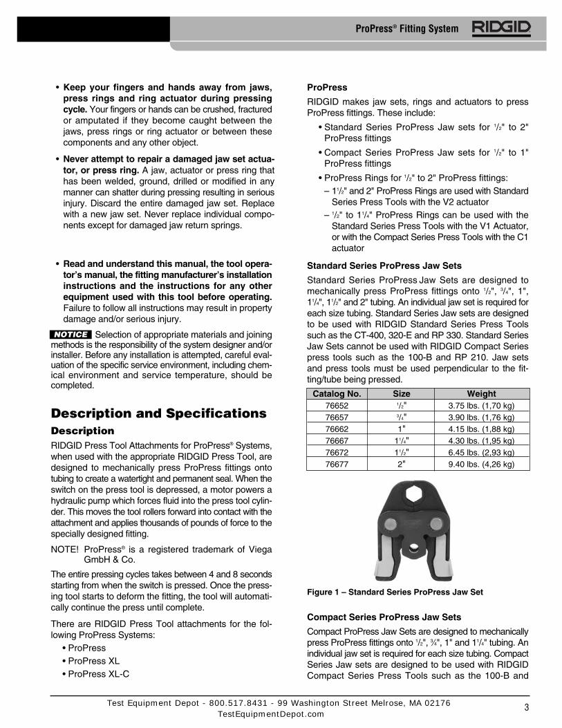
Standard Series ProPress Jaw Sets
Standard Series ProPress Jaw Sets are designed tomechanically press ProPress fittings onto 1/2", 3/4", 1",11/4", 11/2" and 2" tubing. An individual jaw set is required foreach size tubing. Standard Series Jaw sets are designedto be used with RIDGID Standard Series Press Toolssuch as the CT-400, 320-E and RP 330. Standard SeriesJaw Sets cannot be used with RIDGID Compact Seriespress tools such as the 100-B and RP 210. Jaw setsand press tools must be used perpendicular to the fit-ting/tube being pressed.
Figure 1 – Standard Series ProPress Jaw Set
Compact Series ProPress Jaw Sets
Compact ProPress Jaw Sets are designed to mechanicallypress ProPress fittings onto 1/2", 3⁄4", 1" and 11/4" tubing. Anindividual jaw set is required for each size tubing. CompactSeries Jaw sets are designed to be used with RIDGIDCompact Series Press Tools such as the 100-B and
3
ProPress® Fitting System
• Keep your fingers and hands away from jaws,press rings and ring actuator during pressingcycle. Your fingers or hands can be crushed, fracturedor amputated if they become caught between thejaws, press rings or ring actuator or between thesecomponents and any other object.
• Never attempt to repair a damaged jaw set actua-tor, or press ring. A jaw, actuator or press ring that has been welded, ground, drilled or modified in any manner can shatter during pressing resulting in serious injury. Discard the entire damaged jaw set. Replace with a new jaw set. Never replace individual compo-nents except for damaged jaw return springs.
• Read and understand this manual, the tool opera-tor’s manual, the fitting manufacturer’s installationinstructions and the instructions for any otherequipment used with this tool before operating.Failure to follow all instructions may result in propertydamage and/or serious injury.
Selection of appropriate materials and joiningmethods is the responsibility of the system designer and/orinstaller. Before any installation is attempted, careful eval-uation of the specific service environment, including chem-ical environment and service temperature, should becompleted.
Description and SpecificationsDescriptionRIDGID Press Tool Attachments for ProPress® Systems,when used with the appropriate RIDGID Press Tool, aredesigned to mechanically press ProPress fittings ontotubing to create a watertight and permanent seal. When theswitch on the press tool is depressed, a motor powers ahydraulic pump which forces fluid into the press tool cylin-der. This moves the tool rollers forward into contact with theattachment and applies thousands of pounds of force to thespecially designed fitting.
NOTE! ProPress® is a registered trademark of ViegaGmbH & Co.
The entire pressing cycles takes between 4 and 8 secondsstarting from when the switch is pressed. Once the press-ing tool starts to deform the fitting, the tool will automati-cally continue the press until complete.
There are RIDGID Press Tool attachments for the fol-lowing ProPress Systems:
• ProPress• ProPress XL• ProPress XL-C
Catalog No. Size Weight76652 1/2" 3.75 lbs. (1,70 kg)76657 3/4" 3.90 lbs. (1,76 kg)76662 1" 4.15 lbs. (1,88 kg)76667 11/4" 4.30 lbs. (1,95 kg)76672 11/2" 6.45 lbs. (2,93 kg)76677 2" 9.40 lbs. (4,26 kg)
NOTICE
Test Equipment Depot - 800.517.8431 - 99 Washington Street Melrose, MA 02176TestEquipmentDepot.com

Figure 3 – ProPress Ring and V2 Actuator
ProPress XL
RIDGID makes ProPress XL Rings for use with ProPressXL Fittings. ProPress XL Rings are designed to mechan-ically press ProPress XL fittings onto 21/2", 3" and 4" tub-ing. An individual ring is required for each tubing size.ProPress XL Rings are actuated with R2 actuators andStandard Series Press Tools such as the CT-400, 320-Eor RP 330. ProPress XL Rings cannot be actuated withthe Compact Series Press Tools.
ProPress XL rings, actuator and tool must be used per-pendicular to the fitting and tube being pressed. Thepocket/actuator tip feature on the ProPress XL ringsdoes not allow for the tool and actuator to swivel relativeto the ring.
Figure 4 – ProPress XL Press Ring and RIDGID R2Actuator
Ridge Tool Company4
ProPress® Fitting System
RP 210. Compact Series Jaw Sets cannot be used withRIDGID Standard Series press tools such as the CT-400, 320-E and RP 330. Jaw sets and press tools must beused perpendicular to the fitting/tube being pressed.
Figure 2 – Compact Series ProPress Jaw Set
ProPress Rings
ProPress Rings are designed to mechanically pressProPress fittings onto 1/2", 3/4" 1", 11/4", 11/2" and 2" tubing. Anindividual ring is required for each tubing size. 1/2" through11/4" rings can be actuated with either a V1 actuator andStandard Series Press Tools such as the CT-400, 320-E orRP 330, or a C1 actuator and Compact Series PressTools such as the 100-B and RP 210. 11/2" and 2" ringscan only be actuated with the V2 actuator and StandardSeries Press Tools. 11/2" and 2" ProPress rings cannot beactuated with Compact Series Press Tools.
The ProPress rings must be used perpendicular to the fit-ting and tube being pressed but the ball pocket/tip featureon the rings and actuators allows the actuator and presstool to swivel up to 90 degrees in each direction. Thisallows the rings and actuators to be used in some appli-cations where the jaw sets and pressing tool will not fit.The ProPress rings are marked to show the correct actu-ator for use with that ring.
Catalog No. Description Weight27998 1/2" ProPress Ring 0.50 lbs (0,23 kg)28003 3/4" ProPress Ring 0.70 lbs (0,32 kg)28008 1" ProPress Ring 0.90 lbs (0,41 kg)28013 11/4" ProPress Ring 1.00 lbs (0,45 kg)28018 11/2" ProPress Ring 1.35 lbs (0,61 kg)28023 2" ProPress Ring 2.00 lbs (0,91 kg)26163 C1 Actuator 2.10 lbs (0,95 kg)28033 V1 Actuator 4.80 lbs (2,18 kg)21878 V2 Actuator 4.7 lbs (2,13 kg)
Catalog No. Size Weight93677 21/2" XL Press Ring Set 4.5 lbs. (2,04 kg)93682 3" XL Press Ring Set 5.2 lbs. (2,36 kg)93687 4" XL Press Ring Set 6.5 lbs (2,95 kg)93692 R2 Actuator 8.4 lbs (3,81 kg)16803 Carrying Case 9.0 lbs (4,08 kg)
Press Ring ActuatorPocket (Not Visible) R2 Actuator Arm
Side Plate
R2 ActuatorReturn
Spring (NotVisible)
R2 Actuator Pivot PinProPress XL Press Ring
XL Press RingPivot Pin &
Torsion Spring(Not visible)
RIDGID R2 Actuator
R2 ActuatorCylindrical Tip
Catalog No. Size Weight16958 1/2" 2.5 lbs. (1,14 kg)16963 3/4" 2.22 lbs. (1,01 kg)16978 1" 2.28 lbs. (1,03 kg)31228 11/4" 2.56 lbs. (1,15 kg)

ProPress XL-C
RIDGID makes ProPress XL-C Rings for use withProPress XL-C Fittings. ProPress XL-C Rings are de-signed to mechanically press ProPress XL-C fittings onto21/2", 3" and 4" tubing. An individual ring is required for eachtubing size. ProPress XL-C Rings are actuated with V2actuators and Standard Series Press Tools such as theCT-400, 320-E or RP 330. ProPress XL-C Rings cannot beused with the Compact Series Press Tools.
The ProPress XL-C rings must be used perpendicular tothe fitting and tube being pressed but the ball pocket/tipfeature on the rings and actuators allows the actuator andpress tool to swivel up to 90 degrees in each direction.
Figure 5 – ProPress XL-C Press Ring and RIDGID V2Actuator
RIDGID Press Tool Attachments are protected undervarious U.S. and International patents and pending patentapplications, including U.S. patents:
6,434,998 6,477,757 6,694,586 6,729,009 6,923,0377,000,448 7,059,166 7,146,839 7,155,955 7,188,5087,237,427 7,260,975 7,363,799 D562,098
Only use RIDGID Press Tools and RIDGIDpress tool attachments (jaw sets, rings, actuators, etc.)when specified by the fitting manufacturer for use with theirsystem. Use of incorrect press tools and/or attachmentsfor a system can cause system leaks, damage the presstool or attachment, void warranties or cause severe per-sonal injury.
Contact the fitting manufacturer for specificinformation on their system, including compatible tubing,materials, installation instructions, minimum distancebetween fittings, seal material, inspection, testing, etc.Incorrect installation can cause system leaks and exten-sive property damage.
Inspecting the Press Tool andAttachments
WARNING
Inspect your pressing tool and attachments dailyand correct any problems to reduce the risk of seri-ous injury from electric shock, tool and attachmentfailure and other causes and to prevent tool andproperty damage.
1. Inspect press tool according to the specific tool oper-ator's manual.
2. Clean any oil, grease or dirt from the tool and attach-ments, especially the handles and controls. Thisreduces the risk of the tool or attachment slipping fromyour grip and makes inspection easier.
3. Closely inspect all pressing attachment components(jaw sets, rings, actuators, etc.) for any cracked, bro-ken, worn, missing, mis-aligned or binding parts or anyother sign of damage that may prevent proper andsafe operation. Damaged parts can cause the attach-ment to make incorrect pressed connections or failduring use, and cause serious injury or property dam-age. If any damage is found, the attachment shoulddiscarded and replaced.
Always discard the complete pressingattachment. Never replace individual components orexchange parts between assemblies. Failure to replacethe entire assembly may result in component failureand serious injury.
Do not modify pressing attachments or use modifiedattachments. A pressing attachment component thathas been welded, ground, drilled or modified in anymanner can shatter during pressing, resulting in sharp fly-ing objects, severe injury or death. Discard and replacedamaged pressing attachments.
4. Inspect the attachment markings to make sure that itis clearly marked as to the system and size that it isappropriate for. Do not use an attachment that is notclearly marked.
Ridge Tool Company 5
ProPress® Fitting System
Catalog No. Size Weight20543 21/2" XL-C Press Ring 5.46 lbs (2,48 kg)20548 3" XL-C Press Ring 9.63 lbs (4,37 kg)20553 4" XL-C Press Ring 11.08 lbs (5,03 kg)21878 V2 Actuator 6.71 lbs (3,04 kg)21103 Carrying Case 6.15 lbs (2,79 kg)
Press Ring ActuatorPocket (Not Visible) V2 Actuator Arm
V2 Side Plate
V2 ActuatorTorsion
Spring (NotVisible)
ProPress XL-C Press Ring
XL-C Press RingPivot Pin &
Torsion Spring(Not visible)
RIDGID V2 Actuator
V2 ActuatorSpherical Tip
NOTICE
WARNING
WARNING
5. Inspect the press profile of the attachment. If it isrusty, dirty or if there is a build up of fitting material,clean as described in the maintenance section. It isimportant to keep the press profile clean to preventthe formation of burrs during pressing process, pre-vent the attachment from sticking to the fitting andmaking sure that a proper press connection is made.
6. Make sure that springs are intact and bias the attach-ment in the proper direction (closed for rings, jaws andactuators). Attachment should cycle freely from thefully open to fully closed position. If needed, lubricatepivot points with a light lubricating oil. Wipe anyexcess oil from the attachment.
Tool and Work Area Set-UpWARNING
Set up the press tool, attachment and work areaaccording to these procedures to reduce the risk ofinjury from electric shock and other causes and toprevent property damage.
1. Inspect the work to be done and determine• The system of fittings to be used• The sizes of fittings to be used• The amount of space available for the tool and
attachments to make the pressed connections.
2. Determine the appropriate pressing tool and attach-ments for the application. See the Description and Specification section for information on the attach-ments available for the ProPress systems. Information on clearance requirements for various attachments can be found at the back of the manual.
Only use RIDGID Press Tools and RIDGID presstool attachments (jaw sets, rings, actuators, etc.)when specified by the fitting manufacturer for usewith their system. Be sure to use the correct actuatorfor the ring being used. Rings are marked to indicatethe correct actuator for use with the ring. Use of in-correct press tools and/or attachments for a systemcan cause system leaks, damage the press tool andattachment or cause severe personal injury.
3. Make sure that the press tool and attachment havebeen inspected according to their respective manualsor instructions.
4. Follow tool set up procedure according to the specif-ic press tool operator’s manual.
Mounting Attachment Into Press Tool1. Make sure that the press tool is unplugged or that the
battery is removed from the tool.
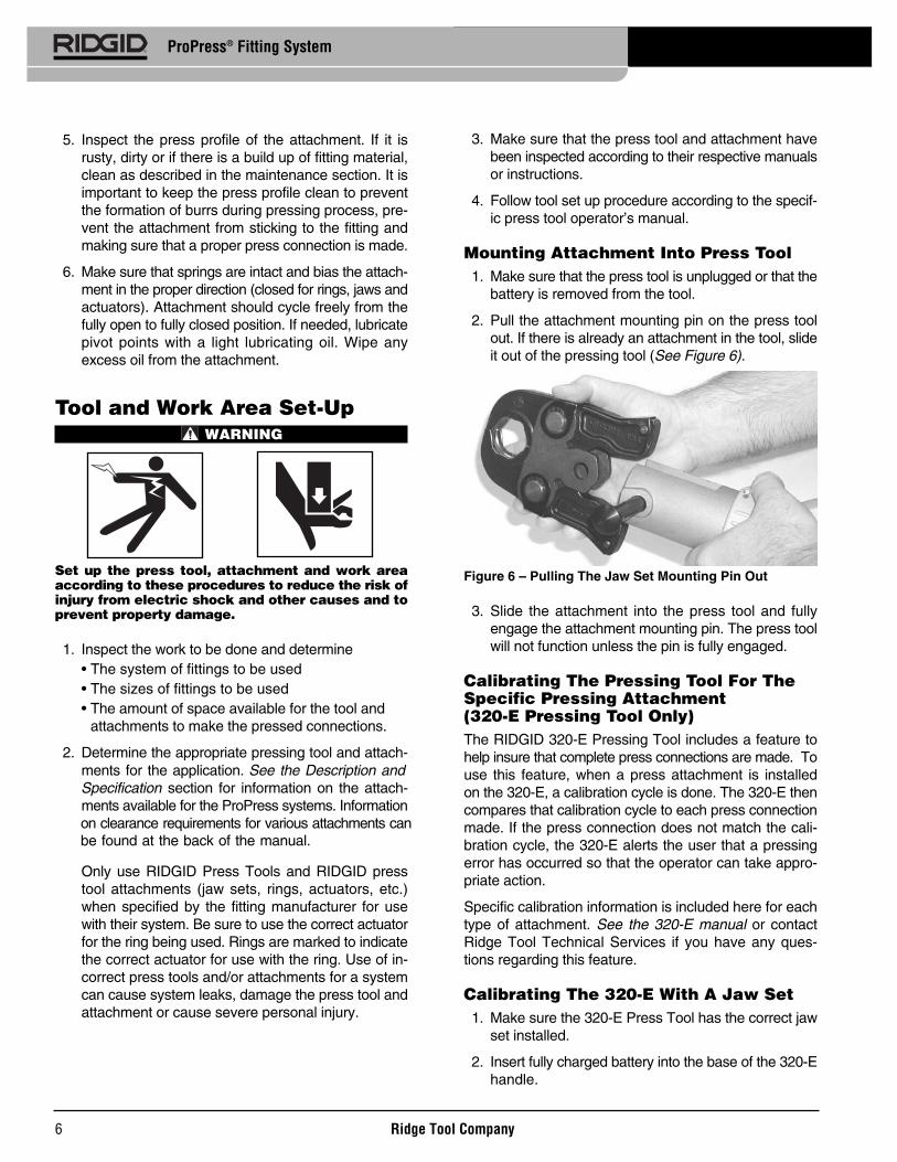
2. Pull the attachment mounting pin on the press toolout. If there is already an attachment in the tool, slideit out of the pressing tool (See Figure 6).
Figure 6 – Pulling The Jaw Set Mounting Pin Out
3. Slide the attachment into the press tool and fullyengage the attachment mounting pin. The press toolwill not function unless the pin is fully engaged.
Calibrating The Pressing Tool For TheSpecific Pressing Attachment (320-E Pressing Tool Only)The RIDGID 320-E Pressing Tool includes a feature tohelp insure that complete press connections are made. Touse this feature, when a press attachment is installedon the 320-E, a calibration cycle is done. The 320-E thencompares that calibration cycle to each press connectionmade. If the press connection does not match the cali-bration cycle, the 320-E alerts the user that a pressingerror has occurred so that the operator can take appro-priate action.
Specific calibration information is included here for eachtype of attachment. See the 320-E manual or contactRidge Tool Technical Services if you have any ques-tions regarding this feature.
Calibrating The 320-E With A Jaw Set1. Make sure the 320-E Press Tool has the correct jaw
set installed.
2. Insert fully charged battery into the base of the 320-Ehandle.
Ridge Tool Company6
ProPress® Fitting System

3. Depress ON/OFF button on display panel one time toturn tool on. The audible alarm should beep once andall three light emitting diodes (LED’s) will blink once.Then, the green LED should be blinking indicating cal-ibration is required.
Tool will automatically go into “sleep” mode if leftunused for ten (10) minutes. To “wake up” tool, it isnecessary to once again depress the ON/OFF buttonon the top display panel.
4. Complete one tool cycle with an empty scissor stylejaw set (no fitting in jaw). Green LED should nowglow solid indicating tool is properly calibrated. Thetool is now ready to begin pressing fittings. The toolwill remain calibrated as long as jaw set is installedunless tool is left idle for longer than sixty (60) minutes.In this instance, which will be indicated by blinkinggreen LED after tool is turned back on, the calibrationprocess must be repeated.
Every time jaw set or actuator is replaced (jaw mount-ing pin is opened), the calibration process should berepeated to allow proper jaw closure detection.
Calibrating The 320-E With The R2Actuator (For Use With ProPress XLRings)1. Insert fully charged battery into the handle of the
320-E press tool.
2. Depress ON/OFF button on display panel one time toturn tool on. The audible alarm should beep once andall three light emitting diodes (LED’s) will blink once.Then, the green LED should be blinking indicating cal-ibration is required.
Tool will automatically go into “sleep” mode if leftunused for ten (10) minutes. To “wake up” tool, it isnecessary to once again depress the ON/OFF buttonon the top display panel.
3. Complete one tool cycle with an empty R2 Actuator(no press ring attached). Green LED will continue toblink but the ram position detection feature is now dis-abled. Due to the design of press rings, it is not pos-sible to detect jaw closure since the rings never fullyclose. The tool is now ready to begin pressingProPress XL fittings. The tool ram position detec-tion will remain disabled as long as the ring actuatoris installed unless tool is left idle for longer than sixty(60) minutes. In this instance, after the tool is turnedback on (by depressing the ON/OFF button on displaypanel) the calibration process must be repeated.
Every time R2 Actuator is replaced the calibrationprocess should be repeated to disable the ram posi-tion detection feature.
Calibrating The 320-E With The V1 OrV2 Actuator (For Use With ProPressRings Or ProPress XL-C Rings)1. Make sure the correct actuator (V1 or V2) is installed
in the 320-E.
2. Insert fully charged battery into the base of the 320-Ehandle.
3. Depress ON/OFF button on the display panel onetime to turn tool ON. The audible alarm should beeponce and all three light emitting diodes (LED’s) willblink once. Then, the green LED should be blinkingindicating calibration is required.
Tool will automatically go into “sleep” mode if leftunused for ten (10) minutes. To “wake-up” tool, it isnecessary to once again depress the ON/OFF buttonon the top display panel.
4. Open the Actuator and engage onto the appropri-ate Press Ring for the application.
5. Complete one tool cycle with the desired Actuator andRing (no fitting in press ring). Green LED should nowglow solid indicating tool is properly calibrated forthe selected Actuator and Ring combination. Thetool is now ready to begin pressing fittings. The toolwill remain calibrated as long as actuator is installedunless tool is left idle for longer than sixty (60) minutes.In this instance, which will be indicated by blinkinggreen LED after tool is turned back on, the cali-bration process must be repeated.
6. If it is desired to change the size of fitting beingpressed and use a different size Ring that works withthe Actuator which is already installed in the tool, it isnecessary to recalibrate the new Ring/Actuator com-bination. To accomplish this, the attachment mountingpin must be partially opened and the fully insertedagain. This action will erase the previous calibrationsetting. The green LED should now be blinking, indi-cating the tool is ready for calibration. Next, repeat step5 for the new Ring/Actuator combination.
Preparing The ConnectionThese are generalized instructions. Always fol-
low the fitting manufacturers specific installation instruc-tions. Failure to follow the fitting manufacturer’s installationinstructions may lead to an improper press connection andcause leaking connections and property damage.
Ridge Tool Company 7
ProPress® Fitting System
NOTICE

Preparing the Tube1. If necessary, cut the desired length of the proper
tube for use with the fitting system. Use a tubingcutter or other method that provides a clean cutsquare to the axis of the tube. If using a vise or othermethod to hold the tube during cutting, make sure thatthe vise is far enough from the end of the tube not todamage the section of tube that is inserted into the fit-ting. Scratches on the outside diameter of the tubeand deformed tube can cause leaks.
2. Deburr the tube end inside and out with a file, ream-er, deburring tool or other suitable tool. Burrs can cutthe sealing element of the fitting and cause leaks.
3. Clean the end of the tube of all dirt, oil and grease.Improperly prepared tube can cause improper con-nections, leaks and other property damage.
Inserting the Tube into the Fitting1. Inspect the fitting per the manufacturer’s instructions
to be sure all parts are present, in place and free ofdirt and debris. If fitting parts are missing or dirty, thiscan cause improper connections, leaks and otherproperty damage. See Figure 7.
Figure 7A – Inspection of the ProPress Fitting per theManufacturer’s Instructions
Figure 7B – Inspection of ProPress XL Fitting Prior toTube Insertion
8
ProPress® Fitting System
Figure 7C – Inspection of XL-C Fitting Prior to TubeInsertion
2. In some systems, there is a requirement to mark thetube before insertion. Check the fitting manufacturer’sinstructions, and if required, mark the tubing with apermanent marker at the appropriate distance fromthe tube end. This gives a visual reference that thetube has been fully inserted into the fitting prior topressing the connection. See Figure 8.
Figure 8 – Marking the Tube Before Inserting Into Fitting
3. Fully insert the tube into the fitting. Most fittings havea stop that the tube end contacts to indicate fullinsertion. Other fittings do not have a stop and willallow the tube to fully pass through the fitting, and aretypically used in repair applications. If there is nostop, insert the tube so that the mark made in the pre-vious step is even with the end of the fitting. In somecases, a twisting motion during insertion makes theprocess easier. Never use any lubricant unless the fit-ting manufacturer specifically advises to. Lubricantscan degrade the seal and cause leaks. Tubing that isdifficult to insert may be out of round or have burrs onthe tube end, which can damage the seal and causeleaks.
4. Make sure that the tube is fully inserted in the fittingand if not marked in previous steps, mark the tube atthe end of the fitting to give a visual reference that thetube is fully inserted. See Figures 9 and 10.
Seal
Stainless SteelGrip Ring
ControlLabel
Seal
GripRing
ControlLabel
Test Equipment Depot - 800.517.8431 - 99 Washington Street Melrose, MA 02176TestEquipmentDepot.com

Pressing the Connection with a Jaw Set1. Squeeze the jaw arms to open the Jaw set and place
the open jaws around the fitting. Allow the jaw set toclose around the fitting, making sure to align thepress profile of the Jaw set with the contour of the fit-ting (See Figure 11).
Figure 11 – Opening the Jaw set and Placing AroundFitting
2. Confirm that the tubing is inserted to the proper depthin the fitting. As specified in appropriate Fitting Systeminstructions.
3. Make sure that the jaw set and pressing tool aresquare to the tube and fitting (See Figure 12) anddepress the press tool switch. Keep fingers andhands away from the jaw set to avoid crushing injuriesin jaw set and between the jaw set and the sur-roundings.
Figure 12 – Jaw Set Square To Fitting and Tubing
The pressing cycle takes 4-8 seconds depending onthe press tool. Once a press cycle begins and therollers contact the Jaw set, the press tool will lock onand automatically complete the press cycle. Releasingthe tool switch will not stop the tool once the pressingprocess has begun. This insures consistent, repeatablepress connection integrity. If the tool should malfunc-tion, refer to the specific press tool operator’s manual.
Ridge Tool Company 9
ProPress® Fitting System
Figure 9 – Marking the Tubing After Fully Inserting Tube
Figure 10 – Inserting the Tube Into Fitting to Proper Depth
Operating InstructionsWARNING
Always wear eye protection to protect your eyesagainst dirt and other foreign objects.
Keep your fingers and hands away from the toolattachment during the pressing cycle. Your fingersor hands can be crushed fractured or amputated inthe attachment or tool or between the attach-ment, work piece and other objects.
Follow operating instructions to reduce the risk ofinjury from crushing and other causes and to pre-vent tool damage.
Only use RIDGID Press Tools and RIDGIDpress tool attachments (jaw sets, rings, actuators, etc.)when specified by the fitting manufacturer for use with theirsystem. Use of incorrect press tools and/or attachments fora system can cause system leaks, damage the presstool or attachment, void warranties or cause severe per-sonal injury.
Confirm that the tool and attachments have been properlyset up.
WARNING

Ridge Tool Company10
ProPress® Fitting System
2. Confirm that the appropriate actuator for the ring to bepressed is in the pressing tool (the ring will be markedwith the designation of the appropriate actuator - R2,V1, V2). The correct actuator/ring combination mustbe used to prevent possible injury, ring and actuatordamage, and improper press connections. If using the320-E Pressing Tool, make sure that the tool andactuator have been calibrated to the ring beingpressed. If not see the calibration information in theSet Up section.
3. Squeeze the actuator arms to open the actuator tips,place tips in ring pockets and allow the actuator toclose down and seat into the pockets. See Figure 14A– C. The R2 actuator must be placed perpendicular tothe fitting/ring to properly seat in the ProPress XL ringpockets, but the V1 and V2 actuators and their matingrings are designed to allow the actuator and tool to berotated up to ninety degrees each way from perpen-dicular. Make sure that the actuator tips are fullyengaged in the ring pockets.
Figure 14A – Placing R2 Actuator Tips Into XL RingPockets
Figure 14B – Placing V2 Actuator Tips Into XL-C RingPockets
4. Press the jaw set jaw arms to open the jaw set andremove from the fitting. Avoid any sharp edges thatmay have formed on fitting during pressing operation.
Pressing the Connection with a Ringand Actuator1. Open the appropriate Press Ring and place square-
ly around the fitting. Allow the ring to close around thefitting, making sure to align the press profile with thecontour of the fitting. If the ring is not properly alignedwith the fitting, an improper press connection will bemade. See Figures 13A, B and C.
Figure 13A – Installing ProPress XL Press Ring OntoFitting
Figure 13B – Installing ProPress XL-C Press Ring OntoFitting
Figure 13C – Installing ProPress Ring Onto Fitting
Detail AProper Press Ring
to Fitting Alignment

supplied by the manufacturer to indicate that the fittinghas not yet been pressed. Removal of the controllabel indicates to others that the connection has beenpressed.
Look for the following:
• Excessive misalignment of the tubes. Note that aslight amount of misalignment at the pressed con-nection is considered normal.
• Tubes that are not fully inserted into the fitting – dou-ble check the insertion marks made on the tube tosee that they are still aligned with the end of the fit-ting.
• Incorrect jaw or ring alignment with the fitting con-tour, distorted or deformed fitting.
• Any other issues per the fitting manufacturer.If any of these problems are found, then removal ofthe fitting is required and a new fitting and tube willneed to be prepared and pressed in its place.
2. If inspecting ProPress fittings, check and confirm thepresence of the ProPress witness mark in one ofthe hex flats (See Figure 15). This unique mark con-firms that the proper RIDGID Jaw set, designedspecifically for the ProPress Fitting System was usedto make the pressed connection. This witness mark isa trade mark of the Ridge Tool Company. Absence ofthe witness mark may invalidate the system manu-facturer’s warranty. The ProPress XL and ProPressXL-C systems do not have a witness mark.
Figure 15 – ProPress Witness Mark
3. Test the system in accordance with the system sup-pliers instructions, normal practice and local codes.The system supplier may have specific system testprocedures to confirm the integrity of the system.
Figure 14C – Placing V2 Actuator Into XL-C Ring PocketsAt An Angle For Additional Clearance
Do not hang the actuator and tool from the ring. Thetool and actuator could fall from the ring and causeserious injury or death.
4. Make sure that the ring is square to the tube and fit-ting and depress the press tool switch. Keep fingersand hands away from the actuator and ring to avoidcrushing injuries in the attachments and betweenthe attachments and surroundings.
The pressing cycle takes 4-8 seconds depending onthe press tool. Once a press cycle begins and therollers contact the actuator, the press tool will lock onand automatically complete the press cycle. Re-leasing the tool switch will not stop the tool once thepressing process has begun. This insures consis-tent, repeatable press connection integrity. If the toolshould malfunction, refer to the specific press tooloperator’s manual.
The ProPress rings and the ProPress XL-C ringsare designed to fully close during the pressing pro-cess. The ProPress XL rings are not designed tofully close during pressing. For the ProPress XLrings, it is normal to have a gap between the ring tipsof approximately 5/16" (8 mm) at the end of the presscycle.
5. After the pressing operation is complete, squeezethe actuator arms to open the actuator tips andremove from the ring.
6. Remove the ring from the fitting. Avoid any sharpedges that may have formed on the fitting duringthe pressing operation.
Inspecting The Press Connection1. Inspect the pressed fitting. If the fitting is supplied with
a control label by the fitting manufacturer, remove it(Refer to Figures 7B and 7C). Control labels are
Ridge Tool Company 11
ProPress® Fitting System
WitnessMark

Maintenance InstructionsWARNING
Press attachments should be removed from presstool before performing any maintenance.
Always wear safety glasses. Protect your eyes fromdirt and other foreign objects.
A jaw, press ring or ring actuator component thathas been welded, ground, drilled or modified in anymanner can shatter during pressing, resulting insharp flying objects, severe injury or death. Discardand replace damaged jaws, press rings or ring actu-ators.
1. Inspect the jaws and press rings inside diameter daily(Figure 17). If rusty, dirty or if there is evidence of fittingmaterial building up on the jaw or ring inside diameter,(fitting material build-up is most likely to occur near thetips of scissor style jaws or press rings as shown inFigure 17) clean with fine grade Scotch-Brite® (Scotch-Brite® is a registered trademark of 3M Company)metal polishing pads (or equivalent), steel wool or asteel bristle wire brush.
Do not clean pressing profile with aggressiveabrasive materials or methods, such as emery cloth,sandpaper, grinding wheels or rotary files. These meth-ods may alter critical pressing profile dimensions andcause improper pressed connections that can lead toextensive property damage.
Figure 17 – Fitting Material Build-Up Requiring JawCleaning
2. Pivot pins and moving points on jaws, press rings andactuators should be cleaned and lubricated at leastonce a month with a light weight general purposelubricating oil.
3. Check return springs in press jaws, rings and ringactuators with each use. Jaws and ring actuatorsshould open and close freely with only moderate fin-ger effort required.
Ridge Tool Company12
ProPress® Fitting System
AccessoriesWARNING
Only the following RIDGID ProPress products havebeen designed to function with RIDGID Press Tools.Other press tool attachments and accessories suit-able for use with other tools may become hazardousand/or produce bad presses.
To prevent serious injury when pressing ProPress fit-tings, only use attachments such as those listedbelow.
ProPress System:Standard Series ProPress Jaw Sets
Compact Series ProPress Jaw Sets
ProPress Rings
CatalogNo. Description
76652 1/2" ProPress Jaw Set76657 3/4" ProPress Jaw Set76662 1" ProPress Jaw Set76667 11/4" ProPress Jaw Set76672 11/2" ProPress Jaw Set76677 2" ProPress Jaw Set
CatalogNo. Description
16958 1/2" ProPress Jaw Set16963 3/4" ProPress Jaw Set16978 1" ProPress Jaw Set31228 11/4" ProPress Jaw Set
CatalogNo. Description
27998 1/2" ProPress Ring28003 3/4" ProPress Ring28008 1" ProPress Ring28013 11/4" ProPress Ring28018 11/2" ProPress Ring28023 2" ProPress Ring26163 C1 Actuator28033 V1 Actuator21878 V2 Actuator28043 C1 Kit, 1/2" - 11/4"27423 V1 Kit, 1/2" - 11/4"28048 V1/C1 Combo Kit, 1/2" - 11/4"27428 V2 Kit, 11/2" - 2"28028 Carrying Case for 1/2" - 11/4" Ring Kits28038 Carrying Case for 11/2" - 2" Ring Kit
NOTICE

13
ProPress® Fitting System
ProPress XL Press Rings
ProPress XL-C Press Rings
CatalogNo. Description
93677 21/2" ProPress XL Press Ring Set93682 3" ProPress XL Press Ring Set93687 4" ProPress XL Press Ring Set93692 R2 Actuator16803 ProPress XL Set Carrying Case93667 R2 Kit, 21/2" - 4"
CatalogNo. Description
20543 21/2" ProPress XL-C Press Ring Set20548 3" ProPress XL-C Press Ring Set20553 4" ProPress XL-C Press Ring Set21878 V2 Actuator21103 ProPress XL-C Set Carrying Case20483 V2 Kit, 21/2" - 4"
Machine StorageThese tools and attachments must be
kept indoors or well covered in inclement weather. Storein a locked area out of the reach of children and peopleunfamiliar with the tools. These tools can cause seriousinjury in the hands of untrained users.
Service and Repair
WARNINGImproper service or repair can make attachmentsunsafe to operate.
The “Maintenance Instructions” will take care of most of the service needs of this machine.
No Service parts are sold for these attachments. If partsare needed, the attachment should be discarded and anew unit purchased.
WARNING
Test Equipment Depot - 800.517.8431 - 99 Washington Street Melrose, MA 02176TestEquipmentDepot.com

Ridge Tool Company14
ProPress® Fitting System
A
B
Clearance Requirements – Compact SeriesProPress Jaw Sets
A
B
C
20°
Tube Dia. A (min.) B (min.)Inches mm Inches mm
1/2" 3/4" 19 2" 513/4" 7/8" 22 23/8" 601" 1" 26 25/8" 67
11/4" 11/8 28 31/8 79
Tube Dia. A (min.) B (min.) C (min.)Inches mm Inches mm Inches mm
1/2" 7/8" 23 13/8" 35 21/2" 643/4" 1" 26 11/2" 38 23/4" 701" 11/8" 29 15/8" 41 3" 7611/4 15/8" 39 21/8" 53 33/8" 85
Tube Dia. A (min.) B (min.)Inches mm Inches mm
1/2" 3/4" 19 15/8" 413/4" 7/8" 22 21/8" 541" 1" 26 21/2" 64
11/4" 11/8" 29 27/8" 7311/2" 13/4" 45 31/2" 892" 2" 51 43/8" 111
Tube Dia. A (min.) B (min.) C (min.)Inches mm Inches mm Inches mm
1/2" 7/8" 23 13/8" 35 21/2" 643/4" 1" 26 11/2" 38 21/2" 641" 11/8" 29 13/4" 45 3" 76
11/4" 11/4" 32 21/4" 57 31/8" 8011/2" 17/8" 48 21/2" 64 33/4" 952" 21/8" 54 31/8" 80 5" 127
B
A
C
A
B
Clearance RequirementsThe following figures illustrate the clearance require-ments for the jaws and fittings and the procedure forpressing fittings in tight quarters with rings.
Clearance Requirements – Standard SeriesProPress Jaw Sets

Tube Dia. A (min.) B (min.) C (min.)Inches mm Inches mm Inches mm
1/2" 15/8" 41 31/4" 83 2" 513/4" 13/4" 45 31/4" 83 17/8" 481" 2" 51 31/4" 83 17/8" 48
11/4" 23/16" 55 33/8" 86 17/8" 46
C1
Tube Dia. A (min.) B (min.) C (min.)Inches mm Inches mm Inches mm
11/2" 23/8" 60 5" 127 23/16" 562" 29/16" 65 43/4" 121 29/16" 65
V2
Ridge Tool Company 15
ProPress® Fitting System
Clearance Requirements – ProPress Rings
B
B
A
Tube Dia. A (min.) B (min.) C (min.)Inches mm Inches mm Inches mm
1/2" 21/4" 57 21/8" 54 11/16" 273/4" 211/16" 68 27/8" 73 11/8" 281" 215/16" 75 35/16" 84 13/16" 31
11/4" 35/16" 84 37/8" 99 13/16" 3011/2" 311/16" 94 45/16" 110 13/16" 312" 47/16" 113 57/16" 139 13/16" 30
A
B
Tube Dia. A (min.) B (min.)Inches mm Inches mm
1/2" 15/8" 41 213/16" 713/4" 13/4" 45 23/16" 551" 2" 51 15/8" 42
11/4" 23/16" 55 215/16" 7511/2" 23/8" 60 35/16" 852" 29/16" 65 41/8" 105
Tube Dia. A (min.) B (min.) C (min.)Inches mm Inches mm Inches mm
1/2" 15/8" 41 39/16" 90 25/16" 593/4" 13/4" 45 35/8" 92 21/8" 551" 2" 51 313/16" 97 23/16" 56
11/4" 23/16" 55 33/4" 92 21/8" 55
B
C
A
C
V1
Ridge Tool Company16
ProPress® Fitting System
Tube Dia. A (min.) B (min.) C (min.)Inches mm Inches mm Inches mm
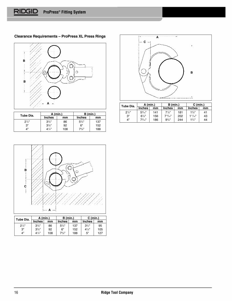
21/2" 59/16" 141 71/8" 181 15/8" 413" 61/8" 156 715/16" 202 111/16" 434" 75/16" 186 95/8" 244 13/4" 44
C
B
A
Tube Dia. A (min.) B (min.)Inches mm Inches mm
21/2" 33/8" 86 53/8" 1373" 35/8" 92 6" 1524" 41/4" 108 73/8" 188
Tube Dia. A (min.) B (min.) C (min.)Inches mm Inches mm Inches mm
21/2" 33/8" 86 53/8" 137 33/4" 953" 35/8" 92 6" 152 41/8" 1054" 41/4" 108 73/8" 188 5" 127
B
B
A
B
C
A
Clearance Requirements – ProPress XL Press Rings

Ridge Tool Company 17
ProPress® Fitting System
1. Place the press ringaround the fitting fromthe front...
2. ...until the press ring isresting in the grooveof the fitting.
3. Keep the press ringclosed and rotate aboutthe fitting until the open-ing is toward the front.
4. Insert the press ringactuator and start thepress cycle.
Tight Quarter Pressing Procedure – Pressing Rings
Tube Dia. A (min.) B (min.) C (min.)Inches mm Inches mm Inches mm
21/2" 63/16" 157 615/16" 176 77/16" 623" 77/16" 189 813/16" 224 27/16" 624" 81/16" 205 107/16" 265 27/16" 62
C
B
A
Tube Dia. A (min.) B (min.) C (min.)Inches mm Inches mm Inches mm
21/2" 41/8" 105 6" 152 41/2" 1143" 45/8" 111 7" 178 47/8" 1244" 5" 127 8" 203 53/4" 146
B
C
A
Tube Dia. A (min.) B (min.)Inches mm Inches mm
21/2" 41/8" 105 6" 1523" 43/8" 111 7" 1784" 5" 127 8" 203
B
B
A
Clearance Requirements – ProPress XL-C PressRings

18
ProPress® Fitting System
SYMPTOM POSSIBLE REASONS SOLUTION
Press connections pro-duced are not complete.
Excessively large orsharp fins present atpress joint parting linewhere jaw or ring tipscome together.
Jaws or rings stick to fit-ting excessively after completing press joint.
Troubleshooting
Used wrong jaw set or press ring for the tube sizeor material.
The jaw set or ring contour was not square to thetube.
The jaw set or ring has exceed life expectations andmay have failed.
Fitting material build up on jaws or press rings inthe contoured profile area near jaw or ring tips.
Excessively worn or damaged jaws or press rings.
Fitting material build-up on jaws or press ring inthe contoured profile area near jaw or ring tips.
Install correct jaw set.
Redo the joint using new tube and fitting and makesure that the jaw set or ring is square to the fitting.
If cracked, replace old jaw set with a new jaw setand redo the joint using new tube and fitting.
Clean jaw or press ring in the contoured areausing metal polishing pads such as Scotch-Brite®.Refer to Maintenance Section for instructions.
Discard jaws or press ring and replace with newRIDGID jaw set or press ring.
Clean jaw or press ring contour area using metalpolishing pads such as Scotch-Brite®. Refer toMaintenance Section for instructions.
Test Equipment Depot - 800.517.8431 - 99 Washington Street Melrose, MA 02176TestEquipmentDepot.com