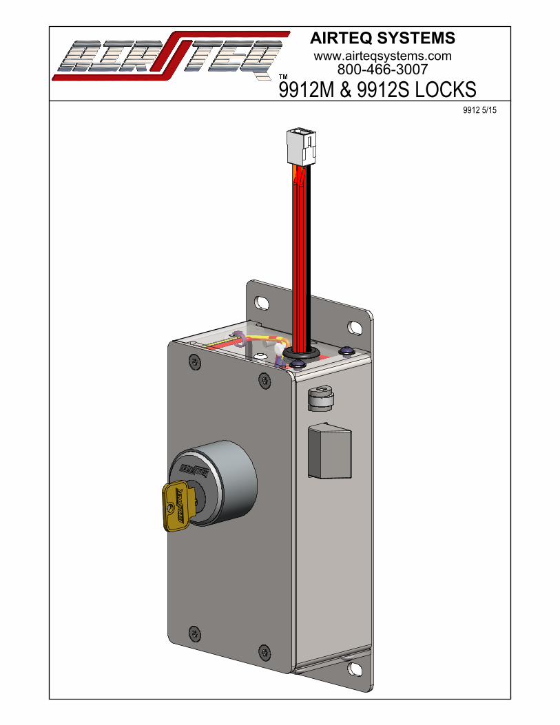
9912 series service manual
TRANSCRIPT
www.airteqsystems.com800-466-3007
9912M & 9912S LOCKS
AIRTEQ SYSTEMS
9912 5/15

9900 Series Lock LHNOTES:1. 146-9900-126L may be substituted for 146-9900-125L in left hand motor locks2. 146-9900-126R may be substitued for 146-9900-125R in right hand motor locks3. Same length button head cap screws may be used in place of hex head cap screws to mount motor/solenoid assemblies to lock body. Specifically item numbers 36 (used to mount solenoid assemblies) and 37 (used to mount motor assemblies)
9900 Series Lock RH
ITEM NO. PART NUMBER DESCRIPTION
1 10002511 Shoulder Screw Ø3/8"x1 1/4", 5/16-18 Nylock2 10002513 Shoulder Screw Ø3/8"x3/8", 5/16-18 Nylock3 10003203 Spring Anchor, 7/8in, 8-32x5/8 Thread, Black Oxide4 10003204 Hook End Ext. Spring, .375"OD, 2.5"Length5 146-9900-107L Actuator Assembly, Left Hand6 146-9900-107R Actuator Assembly, Right Hand7 146-9900-107SL Solenoid Lock Actuator Assembly, Left Hand8 146-9900-107SR Solenoid Lock Actuator Assembly, Right Hand9 146-9900-122 Latchbolt Assembly10 146-9900-124L Left Hand Deadlatch Assembly11 146-9900-124R Right Hand Deadlatch Assembly12 146-9900-125L Deadlatch Catch Indication Assembly, LH13 146-9900-125R Deadlatch Catch Indication Assembly, RH14 146-9900-126L Deadlatch Pivot / Lock Status Switch Mount Assembly, LH15 146-9900-126R Deadlatch Pivot / Lock Status Switch Mount Assembly, RH16 146-9900-272 9900 Key Switch Assembly, Keyed Two Sides17 146-9912M-100L 9900 120VAC Left Hand Motor Assembly
*17* 146-9912M-100L-HC Half Cycle, 9900 120VAC Left Hand Motor Assembly18 146-9912M-100R 9900 120VAC Right Hand Motor Assembly
*18* 146-9912M-100R-HC Half Cycle, 9900 120VAC Right Hand Motor Assembly19 146-9912S-100 9900 120VAC Solenoid Assembly20 146-9924M-100L 9900 24VDC Left Hand Motor Assembly
*20* 146-9924-100L-HC Half Cycle, 9900 24VDC Left Hand Motor Assembly21 146-9924M-100R 9900 24VDC Right Hand Motor Assembly
*21* 146-9924-100R-HC Half Cycle, 9900 24VDC Right Hand Motor Assembly22 150-9900-110L Side Housing Weldment, Left Hand Lock23 150-9900-110R Side Housing Weldment, Right Hand Lock24 160-9912M-100 9912M Main Wiring Harness25 160-9912S-100 9912S Main Wiring Harness26 160-9924-100 9924 Main Wiring Harness27 216-1000-028 Mogul Cylinder, SPANNER Lock NUT28 216-9900-100 Main Housing Back29 216-9900-102 Back Mounting Plate Keyed Back Side30 216-9900-105 Cover Plate31 216-9900-217 Deadlatch Cushion32 216-9900-220L Spring Support Base, LH33 216-9900-220R Spring Support Base, RH34 216-9900-255 RLB Arm35 310-2520-001 BOLT, HEX HD, 1/4-20 X .62 LG, STL, PLATED36 310-2520-004 BOLT, HEX, HD, 1/4-20 X .38 LG., STL, PLATED37 310-2520-045 Screw, BHCS, 1/4-20 X 3/8, Black Oxide38 310-3100-000 Shoulder Screw, Ø5/16"x3/8, 1/4-20x7/1639 311-2520-082 Screw, FH,Pin TORX, 1/4-20x1/2, Stainless Steel, UC Head40 312-3118-004 Thin "Jam" 5/16-18 Nylock nut. McMaster 94945A213 or eq.41 313-3100-005 5/16in D Washer McMaster 96025A167 or Eq.41 313-0000-003 WSHR, LOCK, SPLIT, 1/4, STL, PLTD43 313-0000-120 Fender Washer44 315-9900-001 Spring, .485"OD x 2.25" Length45 315-9900-002 Spring, .405"OD x 2.25" Length46 315-9900-005 .60"ODx1.25"length47 315-9900-010 RLB Catch, Left Hand Torsion Spring48 315-9900-011 RLB Catch, Right Hand Torsion Spring49 315-9900-021 Actuator 360° Right Hand Torsion Spring50 315-9900-022 Actuator 360° Left Hand Torsion Spring51 340-0000-170 Anchor Mount Cable Tie Holder52 340-0000-204 Cable Tie, 4in
REVISIONS
C
B1/25/18Added Half Cycle Part Numbers, 216-9900-205 Now Part
of Motor Assemblies
10/27/15Cumulative: Hex Head motor/sol. mounting screws, add 313-0000-120, add 216-9900-217 for Sol. locks, etc.
11/17/14Initial Release
C
ECN #
11/17/14 RLP
9900 Series 120VAC/24VDC Motor & 120VAC Solenoid Lock
9912M / 9924M / 9912S
APPROV.DATEDESCRIPTIONREV.
SCALE: 1:4 SHEET 1 OF 7
REVDWG. NO.
ASIZE
TITLE:
NAMEDATE
CHECKEDDRAWN
FINISH:
A

51 52 24 29
38
41
44
34
10
22
9
45
550121217
28
30
39
37
47
41 37 52 51
36
16
3941 37 5251 27
27
Mogul Cylinderor Cylinder Extension
Mogul Cylinderor Cylinder Extension
Mogul Cylinder Ring: Length depends on
mogul cylinder
Optional Key Switch Assembly shown
41
43
41
REVISIONS
C
B1/25/18Added Half Cycle Part Numbers, 216-9900-205 Now Part
of Motor Assemblies
10/27/15Cumulative: Hex Head motor/sol. mounting screws, add 313-0000-120, add 216-9900-217 for Sol. locks, etc.
11/17/14Initial Release
C
ECN #
11/17/14 RLP
9912M 120VAC Motor Lock, LH
9912M-LH
APPROV.DATEDESCRIPTIONREV.
SCALE: 1:4 SHEET 2 OF 7
REVDWG. NO.
ASIZE
TITLE:
NAMEDATE
CHECKEDDRAWN
FINISH:
A

51 52 24 30
38
41
44
34
11
23
9
45
6 49 12
13
18
28
29
39
37
41
48
41 37 5251
36
39
39
27
27
51 52 37 41
41
Mogul Cylinderor Cylinder Extension Mogul Cylinder Ring:
Length depends on mogul cylinder
Mogul Cylinderor Cylinder Extension
Optional Key Switch Assembly shown
16
43
REVISIONS
C
B1/25/18Added Half Cycle Part Numbers, 216-9900-205 now a part
of motor assemblies
10/27/15Cumulative: Hex Head motor/sol. mounting screws, add 313-0000-120, add 216-9900-217 for Sol. locks, etc.
11/17/14Initial Release
C
ECN #
11/17/14 RLP
9912M 120VAC Motor Lock, RH
9912M-RH
APPROV.DATEDESCRIPTIONREV.
SCALE: 1:4 SHEET 3 OF 7
REVDWG. NO.
ASIZE
TITLE:
NAMEDATE
CHECKEDDRAWN
FINISH:
A

51 52 25 29
38
41
44
34
10
22
9
45
7501
28
30
39
37
41
47
41 37 52 51
35
39
46
3 44032
16
51 52 4137
1927
27
14
Mogul Cylinderor Cylinder Extension
Mogul Cylinder Ring: Length depends on mogul cylinder
Mogul Cylinderor Cylinder Extension
Optional Key Switch Assembly Shown
41
31
43
REVISIONS
C
B1/25/18Added Half Cycle Part Numbers, 216-9900-205 now a part
of motor assemblies
10/27/15Cumulative: Hex Head motor/sol. mounting screws, add 313-0000-120, add 216-9900-217 for Sol. locks, etc.
11/17/14Initial Release
C
ECN #
11/17/14 RLP
9912S 120VAC Solenoid Lock, LH
9912S-LH
APPROV.DATEDESCRIPTIONREV.
SCALE: 1:4 SHEET 6 OF 7
REVDWG. NO.
ASIZE
TITLE:
NAMEDATE
CHECKEDDRAWN
FINISH:
A

51 52 25 30
38
41
34
11
23
9
45
49 127
29
39
37
41
48
41 37 5251
35
39
39 334 840 3
46
1537415152
19
2728
Mogul Cylinder Ring: Length depends on mogul cylinder
Mogul Cylinderor Cylinder Extension
Mogul Cylinderor Cylinder Extension
44
16
Optional Key Switch Assembly Shown
41
31
43
REVISIONS
C
B1/25/18Added Half Cycle Part Numbers, 216-9900-205 now a part
of motor assemblies
10/27/15Cumulative: Hex Head motor/sol. mounting screws, add 313-0000-120, add 216-9900-217 for Sol. locks, etc.
11/17/14Initial Release
C
ECN #
11/17/14 RLP
9912S 120VAC Solenoid Lock, RH
9912S-RH
APPROV.DATEDESCRIPTIONREV.
SCALE: 1:4 SHEET 7 OF 7
REVDWG. NO.
ASIZE
TITLE:
NAMEDATE
CHECKEDDRAWN
FINISH:
A

2
11
4
3
10
6
5
7
8
9 1
RECOMMENDED SPARE PARTS
*For Half Cycle Locks, 160-9900-150 replaces 340-9900-002
ITEM NO. PART NUMBER Description Spare Parts QTY
1 160-9900-150* Half Cycle Motor Switches and Pigtail* 12 160-9912M-100 9912M Wiring Harness 13 315-9900-001 Dead Latch Spring 14 315-9900-002 Latch Bolt Spring 15 315-9900-010 RLB Spring, LH Lock 16 315-9900-011 RLB Spring, RH Lock 17 315-9900-021 Actuator Spring, RH Lock 18 315-9900-022 Actuator Spring, LH Lock 19 340-9900-002 Roller Arm Switch 1
10 340-9912M-100 9912M Lock, Motor 111 82008802 99 Series Lock Status Switch 1
www.airteqsystems.com800-466-3007
9912M SERIES LOCK
AIRTEQ SYSTEMS
9912M 5-15

1
3
2
6
5
7
8
11
4
10
9
RECOMMENDED SPARE PARTSITEM NO. PART NUMBER Description Spare Parts QTY
1 160-9912S-100 9912S Wiring Harness 12 315-9900-001 Dead Latch Spring 13 315-9900-002 Latch Bolt Spring 14 315-9900-005 9912S Latch Bolt Bumper Spring 15 315-9900-010 RLB Spring, LH Lock 16 315-9900-011 RLB Spring, RH Lock 17 315-9900-021 Actuator Spring, RH Lock 18 315-9900-022 Actuator Spring, LH Lock 19 340-0000-082 Lock Status Switch Body 1
10 340-0000-083 Lock Status Switch Arm 111 340-9912S-100 120VAC Laminated Solenoid 1
www.airteqsystems.com800-466-3007
9912S SERIES LOCK
AIRTEQ SYSTEMS
9912S 12-27-17

D.P.S.
LOCK
3 2 1
23 1
COM
N/O
N/C
(WHT/RED)
(PUR)
(YEL)
(WH
T)
(BLK)
(RED
)
(PUR)
1
N/ON/C
COM
KEY SWITCH LOCK STATUSN/C
N/OCOM
SWITCH
(BLU)
(WHT)
(RED
)
(RED
)
(PUR
)
(BLK)
(BLU)
(YEL)
DOOR POSITION SWITCH N/C (PIN 3)
UNLOCK SIGNAL 120VAC, 1 SEC (PIN 1)
120 VAC NEUTRAL (PIN 3)
LOCK STATUS SWITCH COMMON (PIN 6)
120VAC LINE (PIN 4)
DOOR POSITION SWITCH COMMON (PIN 1)
DOOR POSITION SWITCH N/O (PIN 2)
(RED
)
LOCK STATUS SWITCH N/O (PIN 2)
LOCK STATUS SWITCH N/C (PIN 5)
MOLEX #03-09-1064Pins: (6X) FEMALE .093 DIA
FIELD SIDE WIRINGPIGTAIL
MOLEX #03-09-2062Pins: (6X) MALE .093 DIA
MOLEX #03-06-1032Pins: (3X) FEMALE .062 DIA 24-18 AWG
TINNED AMP#350628-1
MOLEX #03-06-2032Pins: (3X) MALE .062 DIA 24-18 AWG
TINNED AMP #350629-1(NOT REQUIRED WHEN USING
D.P.S. OF OTHER MANUFACTURER)
25
6 3
(OPTION)
MOLEX#19-09-2029Pins: (2X) MALE.093 DIA
120VACMOTOR
(CONT DUTY)
1
25
6 3(RED)
(YEL)
( )
( )
KEY SWITCH N/O
KEY SWITCH COMMON
MOLEX #19-09-1029Pins: (2X) FEMALE .093 DIA
(BRN)4 4
MOTOR CAM
N/O
N/C
COM
SWITCH
(BRN
)
(BLU)
B
CHKDRAWNDESCRIPTIONECNREV
REVISIONS
EL-9912MNONE
4/9/14
RLPWIRING DIAGRAM9912M 120VACMOTOR LOCK
A
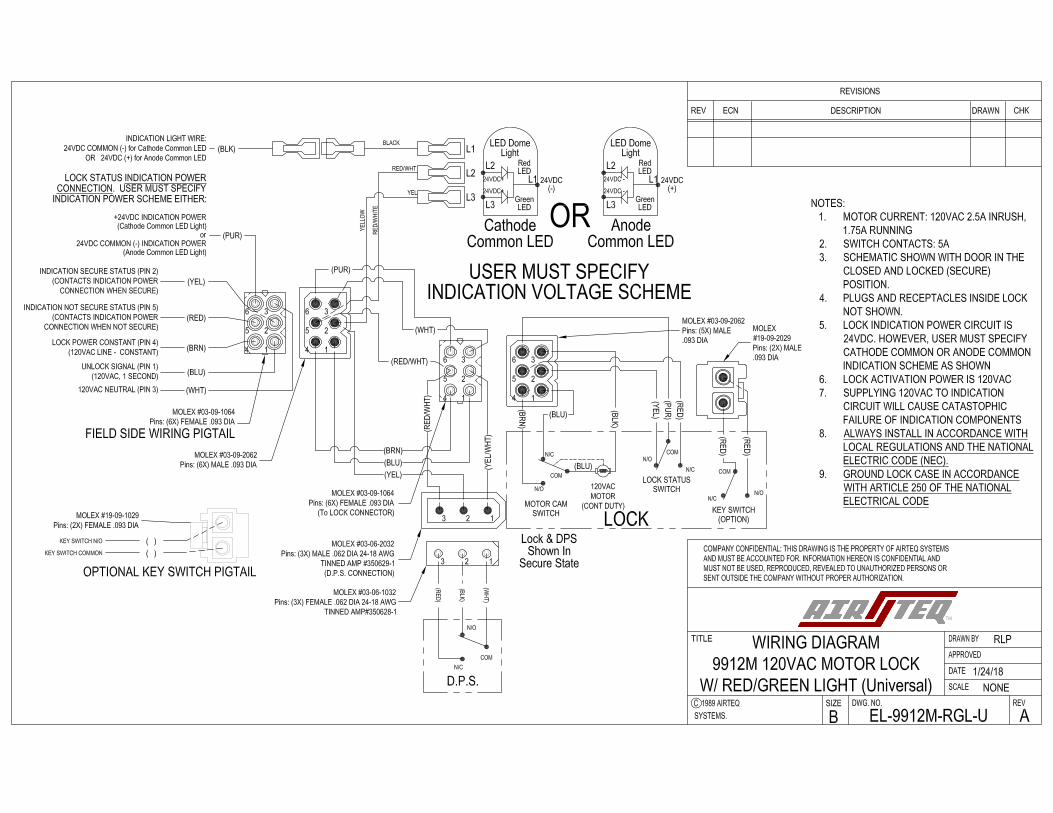
NOTES:1. MOTOR CURRENT: 120VAC 2.5A INRUSH, 1.75A RUNNING2. SWITCH CONTACTS: 5A.3. SCHEMATIC SHOWN WITH DOOR IN THE CLOSED AND LOCKED(SECURE) POSITION.4. PLUGS AND RECEPTACLES INSIDE LOCK NOT SHOWN.5. FOR SERIES LOCK STATUS AND DOOR POSITION SWITCH OPERATION,CONNECT LOCK FIELD SIDE WIRING YELLOW WIRE (LOCK STATUS SWITCHN/O)AND DPS FIELD SIDE PURPLE WIRE (DPS SWITCH N/O). CHECKCONTINUITY BETWEEN LOCK FIELD SIDE PURPLE (LOCK STATUS SWITCHCOM) AND DPS FIELD SIDE WHT/RED (DPS SWITCH COM).6. ALWAYS INSTALL IN ACCORDANCE WITH LOCAL REGULATIONS ANDTHE NATIONAL ELECTRIC CODE (NEC).7. GROUND LOCK CASE IN ACCORDANCE WITH ARTICLE 250 OF THENATIONAL ELECTRICAL CODE

D.P.S.
3 2 1
23 1
COM
N/O
N/C
(WHT/RED)
(PUR)
(YEL)
(WH
T)
(BLK)
(RED
)
(PUR)
1
(BLU)
(WHT)
DOOR POSITION SWITCH N/C (PIN 3)
RETRACT LATCHBOLT, 120VAC, MAINTAINED (PIN 1)
120 VAC NEUTRAL (PIN 3)
LOCK STATUS SWITCH COMMON (PIN 6)
EXTEND LATCHBOLT, 120VAC, MAINTAINED (PIN 4)
DOOR POSITION SWITCH COMMON (PIN 1)
DOOR POSITION SWITCH N/O (PIN 2)
LOCK STATUS SWITCH N/O (PIN 2)
LOCK STATUS SWITCH N/C (PIN 5)
MOLEX #03-09-1064Pins: (6X) FEMALE .093 DIA
FIELD SIDE WIRINGPIGTAIL
MOLEX #03-09-2062Pins: (6X) MALE .093 DIA
MOLEX #03-06-1032Pins: (3X) FEMALE .062 DIA 24-18 AWG
TINNED AMP#350628-1
MOLEX #03-06-2032Pins: (3X) MALE .062 DIA 24-18 AWG
TINNED AMP #350629-1(NOT REQUIRED WHEN USING
D.P.S. OF OTHER MANUFACTURER)
25
6 3
MOLEX#19-09-2029Pins: (2X) MALE.093 DIA
1
25
6 3(RED)
(YEL)
( )
( )
KEY SWITCH N/O
KEY SWITCH COMMON
MOLEX #19-09-1029Pins: (2X) FEMALE .093 DIA
(BRN)4 4
LOCK
N/ON/C
COM
KEY SWITCH LOCK STATUSN/C
N/OCOM
SWITCH
(RED
)
(RED
)
(PUR
)
(BLK)
(BLU)
(YEL)
(RED
)
(OPTION)
120VACMOTOR
(CONT DUTY)
(BRN
)
N/O
COM (BLU)
N/C
N/O
COM (BLU)
N/C
MOTOR CAMOPEN @ 1/2 CYCLE
OPEN SWITCH
MOTOR CAMOPEN @ 1/2 CYCLE
CLOSE SWITCH
B
CHKDRAWNDESCRIPTIONECNREV
REVISIONS
EL-9912M-HCNONE
4/9/14
RLPWIRING DIAGRAM9912M 120VAC RLHB
MOTOR LOCK, HALF CYCLE
A
NOTES:1. MOTOR CURRENT: 120VAC 2.5A INRUSH, 1.75A RUNNING2. SWITCH CONTACTS: 5A.3. SCHEMATIC SHOWN WITH DOOR IN THE CLOSED AND LOCKED(SECURE) POSITION.4. PLUGS AND RECEPTACLES INSIDE LOCK NOT SHOWN.5. FOR SERIES LOCK STATUS AND DOOR POSITION SWITCH OPERATION,CONNECT LOCK FIELD SIDE WIRING YELLOW WIRE (LOCK STATUS SWITCHN/O)AND DPS FIELD SIDE PURPLE WIRE (DPS SWITCH N/O). CHECKCONTINUITY BETWEEN LOCK FIELD SIDE PURPLE (LOCK STATUS SWITCHCOM) AND DPS FIELD SIDE WHT/RED (DPS SWITCH COM).6. ALWAYS INSTALL IN ACCORDANCE WITH LOCAL REGULATIONS ANDTHE NATIONAL ELECTRIC CODE (NEC).7. GROUND LOCK CASE IN ACCORDANCE WITH ARTICLE 250 OF THENATIONAL ELECTRICAL CODE


D.P.S.
LOCK
3 2 1
23 1
COM
N/O
N/C
(WHT/RED)
(PUR)
(YEL)
(WH
T)
(BLK)
(RED
)
(PUR)
1
N/ON/C
COM
KEY SWITCH LOCK STATUSN/C
N/OCOM
SWITCH
(BLU)
(WHT)
(RED
)
(RED
)
(PUR
)
(BLK)
(BLK)
(YEL)
DOOR POSITION SWITCH N/C (PIN 3)
UNLOCK SIGNAL 120VAC, 1 SEC (PIN 1)
120 VAC NEUTRAL (PIN 3)
LOCK STATUS SWITCH COMMON (PIN 6)
VOID
DOOR POSITION SWITCH COMMON (PIN 1)
DOOR POSITION SWITCH N/O (PIN 2)
(RED
)
LOCK STATUS SWITCH N/O (PIN 2)
LOCK STATUS SWITCH N/C (PIN 5)
MOLEX #03-09-1064Pins: (5X) FEMALE .093 DIA
FIELD SIDE WIRINGPIGTAIL
MOLEX #03-09-2062Pins: (5X) MALE .093 DIA
MOLEX #03-06-1032Pins: (3X) FEMALE .062 DIA 24-18 AWG
TINNED AMP#350628-1
MOLEX #03-06-2032Pins: (3X) MALE .062 DIA 24-18 AWG
TINNED AMP #350629-1(NOT REQUIRED WHEN USING
D.P.S. OF OTHER MANUFACTURER)
25
6 3
(OPTION)
MOLEX#19-09-2029Pins: (2X) MALE.093 DIA
120VACSOLENOID
(CONT DUTY)
1
25
6 3(RED)
(YEL)
( )
( )
KEY SWITCH N/O
KEY SWITCH COMMON
MOLEX #19-09-1029Pins: (2X) FEMALE .093 DIA
B
CHKDRAWNDESCRIPTIONECNREV
REVISIONS
EL-9912SNONE
4/9/14
RLPWIRING DIAGRAM9912S 120VAC
SOLENOID LOCK
A
NOTES:1. SOLENOID LOAD: 120VAC 10A INRUSH, .6A SEATED2. SWITCH CONTACTS: 5A.3. SCHEMATIC SHOWN WITH DOOR IN THE CLOSED AND LOCKED(SECURE) POSITION.4. PLUGS AND RECEPTACLES INSIDE LOCK NOT SHOWN.5. FOR SERIES LOCK STATUS AND DOOR POSITION SWITCH OPERATION,CONNECT LOCK FIELD SIDE WIRING YELLOW WIRE (LOCK STATUS SWITCHN/O)AND DPS FIELD SIDE PURPLE WIRE (DPS SWITCH N/O). CHECKCONTINUITY BETWEEN LOCK FIELD SIDE PURPLE (LOCK STATUS SWITCHCOM) AND DPS FIELD SIDE WHT/RED (DPS SWITCH COM).6. ALWAYS INSTALL IN ACCORDANCE WITH LOCAL REGULATIONS ANDTHE NATIONAL ELECTRIC CODE (NEC).7. GROUND LOCK CASE IN ACCORDANCE WITH ARTICLE 250 OF THENATIONAL ELECTRICAL CODE


1
9912 SERIES
LOCK MAINTENANCE
INFORMATION

2
A. Lubrication and Cleaning
1. Each lock is well lubricated at the time of assembly. However, all lubricants deteriorate
eventually and need replacing on a regularly scheduled basis to prevent equipment failure.
Airteq Systems recommends cleaning and lubricating each type of lock according to the
following instructions approximately every (2) years. (Yearly for locks in high use areas,
every 3 to 6 months for exterior locations).
2. General Lubrication:
i. Remove lock cover plate and back plate.
ii. Wipe contaminated/dirty surfaces and remove all foreign material
iii. Lubricate the following areas with Super Lube grease or equivalent (Sythentic lubricant
with PTFE aka Teflon):
• Latch bolt and deadlatch surfaces where they exit the lock body and at the back
‘shafts’ where they enter the guide base.
• Actuator Pivot and Arm where Actuator contacts latch bolt pin
• Dead latch lever where it contacts lock body front and top of actuator
• RLB arm surface where it contacts the actuator roller
• Actuator roller sleeves
• Any other metal on metal sliding surfaces
• Latch bolt beveled surface and strike may be lubricated with stick lubricant as
required. Use PANEF WHITE STICK LUBRICANT WITH SILICONE or equivalent.
3. WARNING
i. Never use WD40 or similar silicone based products as a lubricant
ii. Never use graphite powder
B. Mechanical
1. Check Deadlock Function
i. Press Deadlatch into lock face until DL Link
clears Actuator Arm
ii. Verify Actuator Arm rotates and Contacts
lock face
iii. Verify DL Rocker rotates up completely
(blocking latch bolt pin)
iv. Verify Latchbolt is physically prevented
from being pushed into the lock by the DL
Rocker (i.e. Lock is Deadlocked).
v. If lock does NOT mechanically Deadlock,
troubleshoot and correct before returning lock into service.
2. Check Not Deadlock Function
i. Release Deadlatch
ii. Verify DL Link pushes Actuator Arm away from Lock Face
iii. Verify DL Rocker rotates down (completely clearing Latchbolt pin)
iv. Verify Latch Bolt can freely be pushed into the lock face (i.e. Lock is NOT Deadlocked)
v. If lock does NOT come out of mechanical deadlock when the deadlatch is released,
troubleshoot and correct before returning lock into service.

3
3. Motor or Solenoid Position
i. Verify when motor or solenoid activate that latch bolt pulls back completely
a. Adjust Motor/Solenoid position down if latch bolt doesn’t pull back far
enough
ii. Verify when motor or solenoid returns to locked position that the latch bolt is
completely out, and the actuator can rotate into the deadlock position
a. Adjust Motor/Solenoid position up if actuator is restrained from rotating into
the deadlock position
C. Electrical
1. The electrical actuation system of this lock is
designed for 120 VAC. Any other voltage is not
acceptable.
2. Deadlock status switch function must be
checked during regular lock maintenance/
lubrication.
i. VERIFY CORRECT MECHANICAL
DEADLOCKING OPERATION FIRST
(Steps B.1 and B.2 above)
ii. With lock deadlocked, the DL switch arm
should activate the switch.
a. Via multi-meter, there SHOULD be continuity between switch COM & NO terminals
b. Via multi-meter, there SHOULD NOT be continuity between switch COM & NC
terminals
iii. With lock NOT deadlocked, the DL switch arm should NOT be activating the switch.
a. Via multi-meter, there SHOULD be continuity between switch COM & NC terminals
b. Via multi-meter, there SHOULD NOT be continuity between switch COM & NO
terminals
iv. If the switch arm is not correctly positioned to actuate the switch during mechanical
deadlock, and to release the switch when NOT mechanically deadlocked, adjust/slightly
bend the switch arm.
v. If the switch does not switch and/or release correctly even with proper switch arm
adjustment, replace the switch
vi. NOTE: THE SWITCH MUST REGISTER NOT DEADLOCKED (Step C.2.iii) IN ANY CASE
WHERE THE LOCK IS NOT MECHANICALLY DEADLOCKED. If the lock installation/door
position/door gap does not press the deadlatch sufficiently to activate the lock’s
mechanical deadlocking function, correct the mechanical position of the door/lock until
complete mechanical deadlocking is accomplished. DO NOT ADJUST THE DEADLOCK
STATUS SWITCH TO INDICATE A DEADLOCK CONDITION WHEN THE LOCK IS NOT
MECHANICALLY DEADLOCKED.

4
TROUBLESHOOTING
If the lock is not working properly, the following chart may be used as a guide to locate
and correct the problem.
Because the lock receives its power from the electronic control systems, a thorough
check of the control system should be conducted. Using a volt/ohm meter know to be
accurate, verify the correct power inputs at the appropriate connector pin(s). If the
proper electronic signal is not evident, begin checking “up-stream” from the connector. If
the electronic signal input is correct, the problem is within the locking device, use the
following chart to locate and correct the problem.
The recommended voltage at the lock is 120VAC. If the correct voltage is not evident,
begin checking “upstream” from the lock. If the voltage is correct, the problem is within
the locking device. Use the following chart to locate and correct the problem.
PROBLEM CHECK
LATCHBOLT WILL NOT RETRACT Mechanical Interference Poor on No Power to the Lock Broken or loose wiring Faulty Key Switch
LATCHBOLT WILL NOT EXTEND Mechanical Interference Broken or loose wiring Faulty Key Switch
LOCK RETRACTS BUT WITH LOW STALL FORCE Bad Motor or Lock Connection Low Voltage (Required voltage is 120VAC)
KEY CYLINDER NOT WORKING PROPERLY Mechanical Interference Key Cylinder Engagement/Position in Lock
SECURE LOCK STATUS SIGNAL NOT GIVEN Broken or Loose Wiring Faulty Status Switch Mechanical Deadlock Not Functioning Motor or Solenoid Positioned too Low Switch Arm adjustment
DOOR POSITION SIGNAL NOT GIVEN Broken or Loose Wiring Door Adjustment Needed Magnetic Door Position Sensor adjustment needed