9_borsi_pd_ intro and phenomena.pdf
TRANSCRIPT

Institute of Electric Power Systems – Schering Institute
Partial Discharge- Introduction and Phenomena
Prof. Dr.- Ing. habil. H. Borsi
Institute of Electric Power Systems, Division of High Voltage Engineering
- Schering-Institut -
Leibniz Universität Hannover
Germany

Institute of Electric Power Systems – Schering Institute

PD Classification
• Surface discharges appearing at the boundary of different insulation materials
• Corona discharge occurring in gaseous dielectrics in the presence of inhomogeneous fields
• Internal discharges occurring in voids or cavities within solid or liquid dielectrics
⇒ Continuous impact of discharges in solid dielectrics forming discharge channels (treeing) in organic materials

Institute of Electric Power Systems – Schering Institute
PD Classification
a) corona discharge b) surface discharges
c) discharge in laminated material d) cavity discharge
e) treeing

PD Patterns Source: J. Fuhr, Procedure for Identification and
Localization of PD, IEEE Transactions 2005
Institute of Electric Power Systems – Schering Institute

Institute of Electric Power Systems – Schering Institute

Institute of Electric Power Systems – Schering Institute

Institute of Electric Power Systems – Schering Institute

Institute of Electric Power Systems – Schering Institute

Institute of Electric Power Systems – Schering Institute

Institute of Electric Power Systems – Schering Institute
Why PD-Measurements ?
lPD measurements are an approved tool for insulation condition monitoring lKnown as a precise method lStatement about the actual condition of the insulation possible lAllows to detect very small defects in the insulation lAllows on time maintenance and repair
nPrevents failure and destruction nProlongation of life expectancy nMinimize new investigations nOptimization of the availability
Institute of Electric Power Systems – Schering Institute

Institute of Electric Power Systems – Schering Institute
Purpose
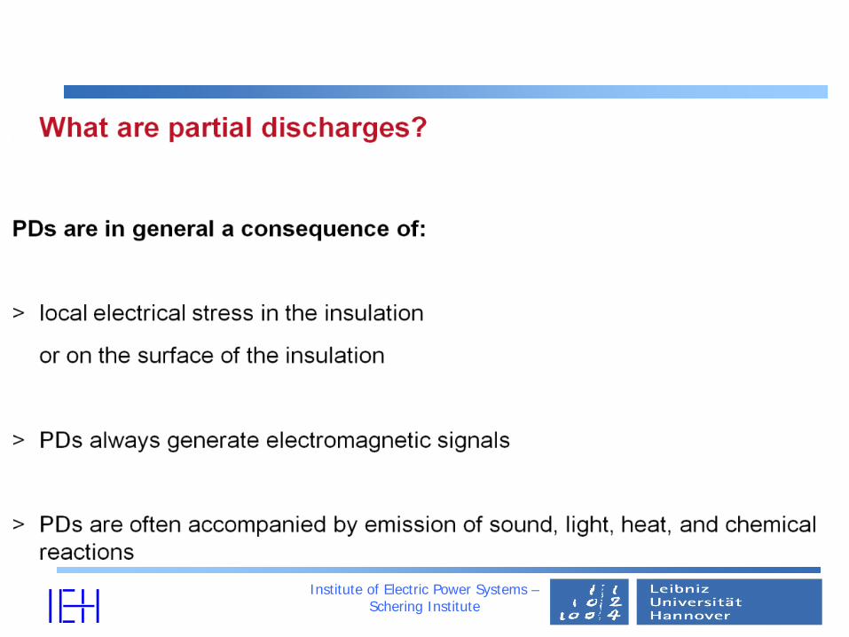
• Partial discharges are a sensitive measure of local electrical stress
• Partial discharge inception voltage gives an information on the limit of the electrical strength of an insulating material
• Partial discharge measurement is a typical non destructive test

Institute of Electric Power Systems – Schering Institute
PD-Monitoring and Diagnostic
• Major changes in the insulation systems are reflected in the partial discharges (PD)
• The partial discharge is a symptom of most (but not all)
deterioration mechanisms

Institute of Electric Power Systems – Schering Institute
Advantages of PD-Measuring
• Non-destructive diagnosis method
• Detection of locally limited defects
• Identification of PD sources
• On- or off-line measurement

Institute of Electric Power Systems – Schering Institute
Insulating Material Model
•Simplified failure within a solid insulating material
C3 C3
C2
C2
C1
C1 = cavity
C2 = part of insulating material (only marked cylinder)
C3 = part of insulating material

Institute of Electric Power Systems – Schering Institute
Cp Cp
Cs
Cs
C1
Cp'
Cs'
C1 RF
u
u1
i1
i
c)b)a)

Institute of Electric Power Systems – Schering Institute
Equivalent Circuit
•U = applied voltage at power frequency •C1 = capacitor representing the cavity •C2 = capacitor representing the insulating material around the cavity •C3 = capacitor representing the remaining insulating material •S = spark gap representing the discharge of the capacitor C1
UC 1
C 3
C 2
S

Institute of Electric Power Systems – Schering Institute
PD-Principle
Uz
U1(t)Ut(t)
U'1(t)-Uz
tUL
-UL
FCUq .1∆=
I1(t)
t
∫= dttiq ).(1
B
A
εr
B
A
CP
CS
CF
R1
S I1(t)
Ut U1
Is(t)
I2(t) I3(t)
ε0 CP/2 CP/2
2CS
2CS
CF

Institute of Electric Power Systems – Schering Institute
•Acoustic PD detection – No determination of apparent charge – Insufficient due to high damping of the solid
insulation •Electrical PD measurements
– Broadband • Large-scaled • Suppression of noises difficult
– Narrowband • Suppression of noises possible • Preferable despite complicated adjustment on-site
Institute of Electric Power Systems – Schering Institute
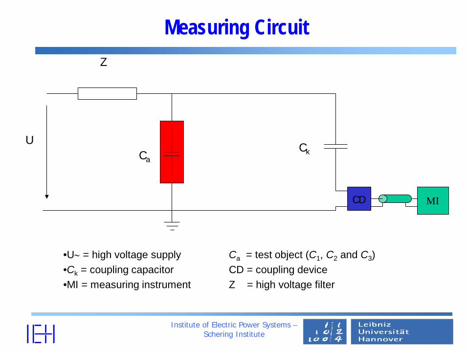
Measuring Circuit
•U∼ = high voltage supply Ca = test object (C1, C2 and C3) •Ck = coupling capacitor CD = coupling device •MI = measuring instrument Z = high voltage filter
U Ca
Ck
CD MI
Z

Institute of Electric Power Systems – Schering Institute
PD-Measurement Principle
Kt
KsK
KPS
S
Fm CC
CqCCCC
CC
qq+
≈++
= ...1.SFP CCC ,>>
Z
Ct U ~
A
B
Is
CK Im(t)
Cc Zm Um
Measuring Impedance
M Amp. Filter

Institute of Electric Power Systems – Schering Institute
Institute of Electric Power Systems Schering-Institut
Theoretical Background
Important PD-Parameters
Apparent charge Phase angle of the PD pulse related to the applied voltage PD sorce

Institute of Electric Power Systems – Schering Institute
Partial Discharge Parameter
•of a PD pulse is that charge, if injected within a very short time between the terminals of the test object in a specified test circuit, would give the same reading on the measuring instrument as the PD current pulse itself
• apparent charge q

Institute of Electric Power Systems – Schering Institute
Partial Discharge Parameter
•applied voltage at which repetitive PD are first observed in the test object when the voltage is gradually increased
• partial discharge inception voltage
applied voltage at which repetitive PD cease to occur when the voltage is gradually decreased
• partial discharge extinction voltage
Institute of Electric Power Systems – Schering Institute
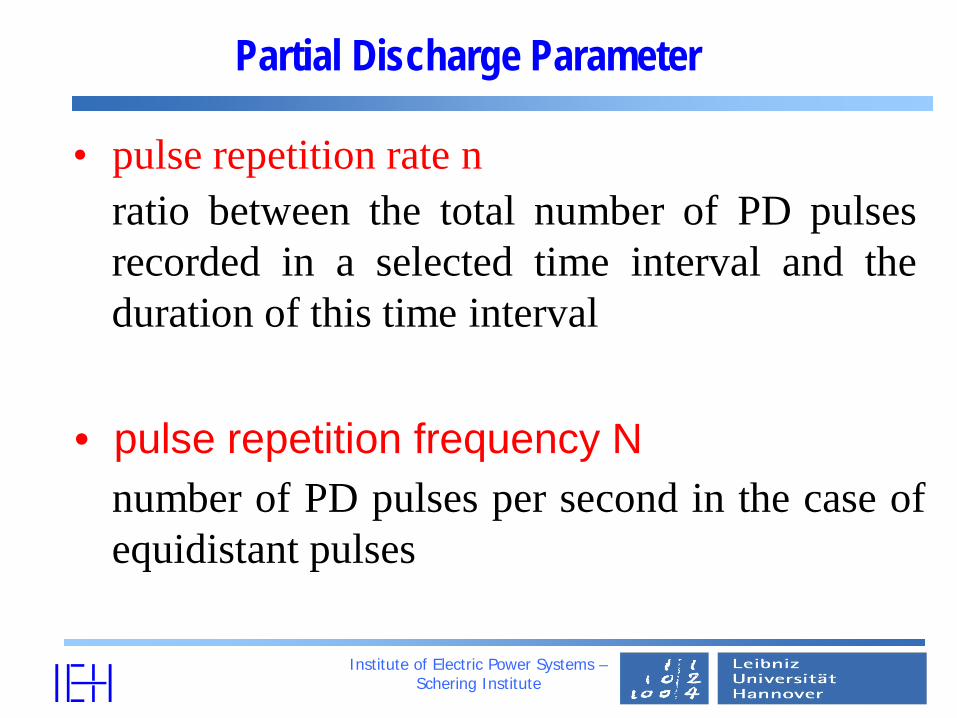
Partial Discharge Parameter
• pulse repetition frequency N
• pulse repetition rate n ratio between the total number of PD pulses recorded in a selected time interval and the duration of this time interval
number of PD pulses per second in the case of equidistant pulses

Institute of Electric Power Systems – Schering Institute
Frequency Response of PD Measuring System
•A - bandpass of the measuring system •B - frequency spectrum of the partial discharge pulse •C - frequency spectrum of a calibration pulse •f1 - lower frequency limit f2 - upper frequency limit
frequency
-6 dB
A A
f 1 f 2
B C

Institute of Electric Power Systems – Schering Institute
PD Measuring Systems
•Wide-band measuring system 30 kHz ≤ f1 ≤ 100 kHz
f2 ≤ 500 kHz 100 kHz ≤ ∆f ≤ 400 kHz
•Narrow-band measuring system 9 kHz ≤ ∆f ≤ 30 kHz 50 kHz ≤ fm ≤ 1 MHz

Institute of Electric Power Systems – Schering Institute
On-site Detection Methods
Electrical measurements noise
Acoustic measurements sensitivity calibration
“Chemical measurements” gas-in-oil-analysis

Institute of Electric Power Systems – Schering Institute
Kind of Noise for Electrical Measurements
External noise • power line conducted noise like corona,
signals from electronic power devices, • irradiated noise like electromagnetic
interference due discharges, radio station, power line carrier, etc.
Internal noise • cross-talking between phases

Institute of Electric Power Systems – Schering Institute
PD-Measurement System
Ct
Zm C2
CK
R HV-Transformer
Amplifier
A/D Conversion Digital Signal Processor
Computer Interface Computer/Software/User
Panel
PD-Signal
Voltage Signal
PD Measurement System
Coupling Capacitor
Measuring Impedance
0-22
0 VA
C
Test Object

Institute of Electric Power Systems – Schering Institute
PD-Parameter
∑=i
iqT
I 1
∑=i
iqT
D 21
∑=i
ii uqE .
• Average Discharge Current (I)
• Quadratic Rate (D)
• PD Energy (E)
• PD Power Loss (P)
• PD Repetition Rate (R) ∑=i
ii uqT
P .1

Institute of Electric Power Systems – Schering Institute
PD-Parameter
• PD Inception Voltage (PDIV)
• PD Extinction Voltage (PDEV)
• PD Aparent Charge


Institute of Electric Power Systems – Schering Institute
PD Monitoring
Possible methods:
Apparent charge
PD- localization
Acoustic
UHF
Narrowband electrical
Wideband electrical

Institute of Electric Power Systems – Schering Institute
On line PD measurement • Difficulties by on line measurement
ØExpenditure digital signal processing because of the influence of ambient noises
Ü Continuously sinusoidal noise signals Ü Phase synchronous noise signals Ü Stochastically noise signals (Corona)
Alteration of the pulse shape ?
Before filtering
After filtering

PD-Measurement on
Transformers
Institute of Electric Power Systems – Schering Institute

Institute of Electric Power Systems – Schering Institute
Possible measurements
Measurement
on a
110kV/35kV
40MVA
transformer

Institute of Electric Power Systems – Schering Institute
Electrical fault detection Bushing
Capacitive sensor AKV FO-
Sender
FO- Receiver
DSO
Quadripole coupling
dB
amplification: 0 - 60 dB Bandwidth FO: > 10 MHz (3dB)
Patented sensor for decoupling of
capacitive signals

Institute of Electric Power Systems – Schering Institute
Online PD Measurement
Signal decoupling

Institute of Electric Power Systems – Schering Institute
Possible measurements
Amplifier + FO-Sender
AKV
Sensor
FO-Cable

Institute of Electric Power Systems – Schering Institute
Possible measurements
U (200mV/div)
V (200mV/div)
W (200mV/div)
MP (50mV/div)
Time Line = 10 Periods Time = 1µs/div
Good SNR
Perhaps PD-Signal

Institute of Electric Power Systems – Schering Institute
Possible measurements
Impulse Charge > 5000 pC
Apparent Charge per Period > 500 nC
Impulse Charge < 200 pC
Apparent Charge per Period < 2000 pC 0 10 20 30 40 50
-1
-0.5
0
0.5
1
Time[ms]
0 10 20 30 40 50-4
-2
0
2
4
Time[ms]
0 10 20 30 40 50-1
-0.5
0
0.5
1
0 10 20 30 40 50-4
-2
0
2
4
0 10 20 30 40 50-4
-2
0
2
4
0 10 20 30 40 50-1
-0.5
0
0.5
1
Volta
ge [V
] Vo
ltage
[V]
• Online measurement A: Phase V (110kV/35kV/40MVA)
• Online measurement B: Phase W (220kV/118kV/150MVA)

Institute of Electric Power Systems – Schering Institute
Schematic diagram
winding PD ???
bushing
xD (t)
neutral
xS (t)
section PD ???
PD

Institute of Electric Power Systems – Schering Institute
Analysis of measured PD-signals
0
-5
5
0
-0.05
0.05at the bushing
at the neutral
calculated from bushing
calculated from neutral
0
-5
5
Origin 3
0
-5
5
Origin 5
0 50
Measured data Origin 1
10 20 30 40 0 5010 20 30 40
Time in µs

Sources of noise in a PD circuit
Institute of Electric Power Systems – Schering Institute
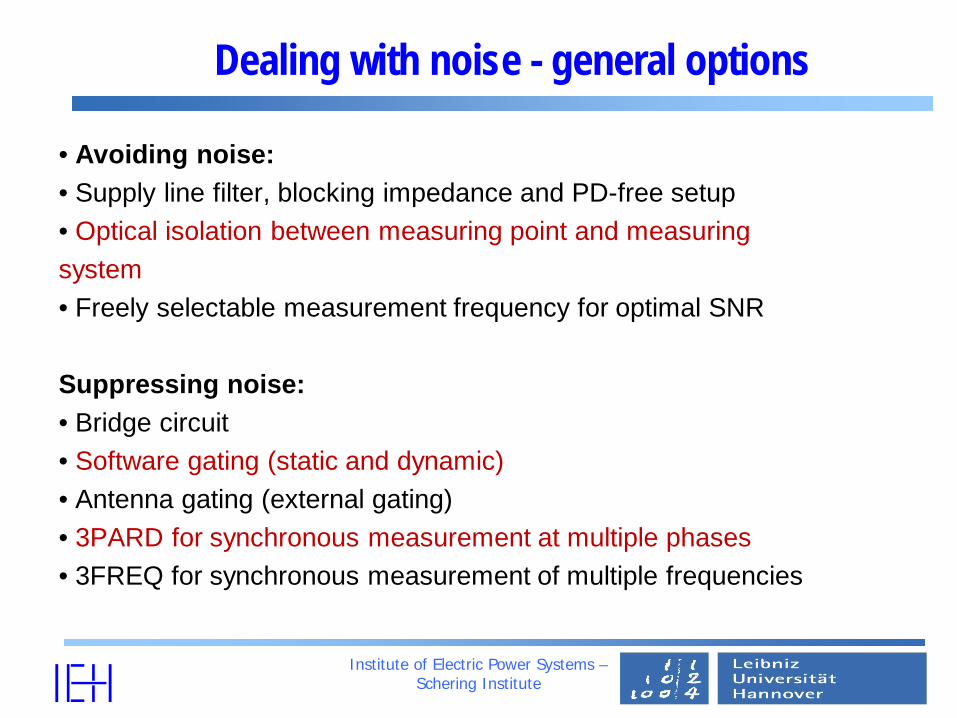
Dealing with noise - general options
• Avoiding noise: • Supply line filter, blocking impedance and PD-free setup • Optical isolation between measuring point and measuring system • Freely selectable measurement frequency for optimal SNR Suppressing noise: • Bridge circuit • Software gating (static and dynamic) • Antenna gating (external gating) • 3PARD for synchronous measurement at multiple phases • 3FREQ for synchronous measurement of multiple frequencies
Institute of Electric Power Systems – Schering Institute
Institute of Electric Power Systems – Schering Institute

PD Measurements on
Electrical Mashins
Institute of Electric Power Systems – Schering Institute

Typical PD sources in electrical machines
A. Slot discharge, semi-conducting paint abrasion due to loss wedges and bar vibration
B. Delamination in interface of main insulation and copper conductor due to load changes and
different thermal expansion of main insulation and copper
C. Internal discharge due to delamination between layers of main insulation due to overheating and
aging of the main insulation D. Local highest electrical field on sharp edges of
copper conductor E. Treeing in insulation layers
F. Internal discharges due to voids and cavities in layers of insulation
F
A B
C
E
D

Typical PD sources in electrical machines G. End-winding discharge due to defect on
grading coating, contamination in end-winding, aging or invalidate the proper
function of field grading H. Delamination of insulation in elbow (especially when manually manufactured)
I. Discharge on connection area between slot corona protection and end-winding
corona protection due to contact problem, contamination or potential shift
J. Insufficient spacing, tracking, especially between bars with big voltage difference,
different phases or bar and pressure fingers
K. Crack of the insulation directly at the slot exit due to mismatch of the thermal
expansion of the bar versus the stator core
G H
I
J
K

Testobject
Stator bar
Stator slot model
Cooling duct
Semi-conductive coating Corona protection coating Copper conductor

PD pattern recognition simulation of the slot discharge
without defect, 10kV, 25°C a=10 mm, b=10 mm, 10kV, 25°C
a=20 mm, b=20 mm, 10kV, 25°C a=30 mm, b=20 mm, 10kV, 25°C
b
Defect on semi-conductive screen
a

PD pattern recognition simulation of the insufficient spacing between bar and pressure fingers
HV
metal
PD-Measurements on
Cables
Institute of Electric Power Systems – Schering Institute

Differential Diagnostic Methods PD-sensor in a cable link

Differential Diagnostic Methods PD-sensor in a cable link
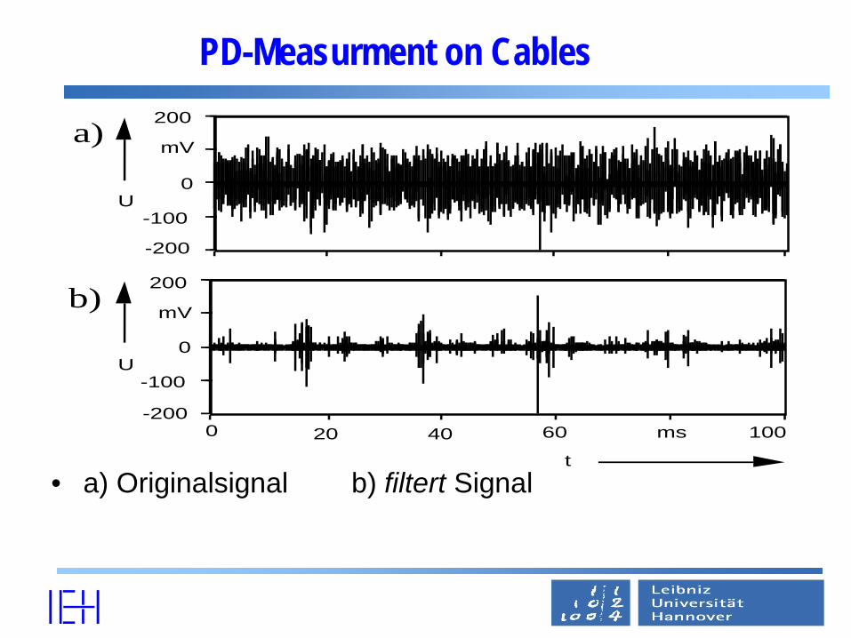
PD-Measurment on Cables
• a) Originalsignal b) filtert Signal
U
a)
b)
t
U
0 20 40 60 ms 100
0
200
mV
-200
-100
0
200
mV
-200
-100

PD-Measurment on Cables
• a) Originalsignal b) filtert Signal
U
t0 4 8 12 ms 20
U0
60
mV
-60
0
40mV
-40-20
-60
-30 5 µsC
Rog
b)
c)

PD Measurement
• PD measurement on a 3 phase cable system