9hvvho 9lhz 0dqxdo 6hsw - seaboard marine · pdf filefault icons ... 77 viewing tab position...
TRANSCRIPT

Vessel View ManualSept 2010
90-8M0050668 SEPTEMBER 2010 Page i
TABLE OF CONTENTS
Section 1 - Getting Started
VesselView Specifications.........................................................2Overview....................................................................................2Keypad Functions......................................................................3
"X" Button.............................................................................3Check Button........................................................................3Arrow Pad.............................................................................4Propulsion, Vessel, or Environment and Navigation Buttons.............................................................................................4
Brightness and Alarm Button................................................4Keypad Transfer...................................................................4Menu Button.........................................................................4
Turning the VesselView Unit On or Off......................................4Restarting VesselView...............................................................4Cleanliness and Care of Product...............................................4Saving the Settings....................................................................5
Section 2 - Setup and Calibration
Setup Wizard Overview.............................................................8Setup Wizard.............................................................................8
Import Configuration (Optional)............................................8Engine Setup...........................................................................10Display Setup...........................................................................11Device Setup............................................................................12
Device Setup Complete......................................................16Calibration Menu Options........................................................16Calibrating the Tanks...............................................................17
Tank and Location Selection..............................................17
Tank Calibration.................................................................18Method 1: Default.........................................................18Method 2: Manual.........................................................18
Tab Setup and Calibration.......................................................20Calibrating Trim........................................................................23
Trim Calibration..................................................................23Configuration............................................................................24Factory Reset...........................................................................25Save Configuration..................................................................26Load Configuration...................................................................28
Section 3 - Screen Overview and Operation
Identifying and Using Screen Categories.................................32Available VesselView Display Screens ...................................32
MerCruiser Display Screens...............................................33Outboard and Jet Drive Display Screens...........................34
VesselView Display Screens...................................................34Propulsion..........................................................................34Vessel.................................................................................37Environment and Navigation..............................................38
VesselView Setup Screens......................................................40Calibrate.............................................................................40Settings..............................................................................41
Alarms................................................................................44System Info........................................................................44
Checking Status Using the Status Bar.....................................44Fault Icons..........................................................................45Fuel Alarms........................................................................46
Using the Menu Panel..............................................................47Navigating Through the Screens........................................48
Using Pop‑Up Windows...........................................................49Alarms and Faults..............................................................49Screen Brightness..............................................................49
Section 4 - Main Menu
Favorites..................................................................................52Calibrate Menu.........................................................................52
Tank Menu.........................................................................52Tabs Menu.........................................................................52Trim Menu..........................................................................52Configuration Menu............................................................52Factory Reset Menu...........................................................52Save Configs Menu............................................................53Load Configs Menu............................................................53
Settings....................................................................................53Settings Menu Options.....................................................53Status Bar Options............................................................54Steering Options...............................................................54
Pages On/Off Options.......................................................55Page/Screen Favorites.................................................56
Trim Setting......................................................................56Tab Settings......................................................................57Autopilot Config................................................................57Clock/Light........................................................................58Preferences......................................................................59Boat Speed.......................................................................60Warnings...........................................................................61Units..................................................................................61Units 2...............................................................................62Offsets..............................................................................63
Alarms......................................................................................64

Page ii 90-8M0050668 SEPTEMBER 2010
Alarms Menu Options......................................................64VesselView Warning Horn Strategy................................ 64Active Alarms.................................................................. 65
Fault Icons...................................................................66Viewing Active Alarms.................................................67Viewing Alarm Details................................................. 68
Alarm History...................................................................68
Alarm History Details...................................................68Clearing Alarm History................................................ 69
System Information.................................................................70System Information Menu Options..................................70Software Information....................................................... 70Hardware Information......................................................71
Section 5 - Propulsion Menu
Using Propulsion Screens ..................................................... 74Available Propulsion Screens..........................................74Viewing Engine Status.................................................... 74Viewing Performance and Fuel....................................... 75
Resetting Total Fuel Used...........................................75Viewing Peak Performance.............................................76
Resetting Peak Values................................................76Viewing Steering Position (MerCruiser Only)..................76Viewing Trim Position......................................................77Viewing Tab Position (Diesel Only).................................78Viewing Boost Pressure (Optional)................................. 78
Using Troll Control...........................................................79Setting Troll Control.................................................... 79
Viewing Demand and Load (Diesel only)........................ 80Viewing Transmission Data (Diesel only)........................80Viewing Intake Data (Diesel only)................................... 81Using Cruise Control....................................................... 81
Setting the Cruise Control...........................................81Using Smart Tow.............................................................82Setting Cruise with Smart Tow........................................82
Setting Smart Tow Launch Control............................. 83
Section 6 - Vessel Menu
Using Vessel Screens............................................................ 86Checking Vessel Status....................................................86Checking Tank Status.......................................................87
Viewing Steering Position (MerCruiser Only)................... 88Viewing Generator Data................................................... 88
Section 7 - Environment and Navigation Menu
Using Environment and Navigation Screens..........................90Environment and Navigation Screens.............................90Viewing Depth and Water Temperature..........................90
Setting Depth Alerts.................................................... 91Viewing Trip Log Information...........................................92
Resetting Trip Log Amounts........................................92Viewing Fuel to Waypoint Data....................................... 93Viewing Navigation Data................................................. 93
Viewing Autopilot Data (Zeus and Axius Only)................ 94Standby.......................................................................94Track to Waypoint....................................................... 95Waypoint Sequence....................................................95Skyhook Station Keeping............................................97VesselView Skyhook Screens.....................................99Joystick Screen.........................................................100
Section 8 - Glossary of Terms
VesselView Systems Terminology.......................................102
Section 9 - Customer Assistance Information
Product Repair and Service..................................................106Service Away from Home.....................................................106Parts and Accessories Inquiries...........................................106Service Assistance...............................................................106
Mercury Marine Service Offices...........................................106Marine Repair Logistics........................................................107Local Repair Service............................................................107Service Away From Home....................................................107

Section 1 - Getting Started
90-8M0050668 SEPTEMBER 2010 Page 1
Section 1 - Getting StartedTable of ContentsVesselView Specifications...................................................... 2Overview................................................................................. 2Keypad Functions................................................................... 3
"X" Button ....................................................................... 3Check Button .................................................................. 3Arrow Pad ....................................................................... 4Propulsion, Vessel, or Environment and NavigationButtons ........................................................................... 4
Brightness and Alarm Button .......................................... 4Keypad Transfer ............................................................. 4Menu Button ................................................................... 4
Turning the VesselView Unit On or Off................................... 4Restarting VesselView............................................................ 4Cleanliness and Care of Product............................................ 4Saving the Settings................................................................. 5
1

Section 1 - Getting Started
Page 2 90-8M0050668 SEPTEMBER 2010
VesselView SpecificationsComponent SpecificationPower/digital communications 2–24 pin VesselView female harness connectors
USB port V1.1 or V2.0 (that is stated to be backwards compatible to V1.1)IMPORTANT: VesselView unit will not recognize memory sticks that are only V2.0 compatible.
Ethernet port For future option
VesselView unit dimensionsModule 180.5 mm x 112.0 mm
(7.1 in. x 4.4 in.)
Bezel 197.8 mm x 132.5 mm(7.8 in. x 5.2 in.)
Net weight (without harness) 0.82 kg (1.8 lb)
OverviewIMPORTANT: This VesselView is compatible with products manufactured by Mercury Marine Outboards, Mercury MarineMerCuiser, and Cummins MerCruiser Diesel. Some of the functions explained in this manual will be disabled depending on thepower package it is connected to.VesselView is a comprehensive boat information center that can display information for up to three gasoline or diesel engines.VesselView can also link gauge support for a fourth gasoline engine. It continuously monitors and reports basic operating dataincluding detailed information such as seawater temperature and depth, trim status, boat speed and steering angle, and the statusof fuel, oil, water, and waste tanks.VesselView can be fully integrated with a vessel’s global positioning system (GPS) or other NMEA‑compatible device to provideup to the minute navigation, speed, and fuel‑to‑destination information.VesselView is equipped with a USB port that enables configuration settings to be saved to, or imported from, a USB memory stick.
VesselView display screens are grouped intothree categories:
a - Propulsion button enables you to quicklyaccess the propulsion screens that arerelated to propulsion, trim, tabs, andengine performance
b - Vessel button enables you to quicklyaccess the vessel screens that arerelated to fuel use, tank levels, and otheritems such as generators
c - Environment and Navigation buttonenables you to quickly access theenvironment and navigation screens thatare related to depth, navigation, and GPS
32711
a
b
c

Section 1 - Getting Started
90-8M0050668 SEPTEMBER 2010 Page 3
Keypad FunctionsMounted on the VesselView are seven buttons and an arrow pad for easy navigation through the screens and pages.
a - "X" buttonb - Check buttonc - Arrow padd - Propulsion buttone - Vessel buttonf - Environment and navigation buttong - Brightness and alarm buttonh - Menu button
A dash‑mounted multifunction VesselView keypad is available as an accessory that offers the same eight buttons and an arrowpad for easy navigation through the screens and pages. The dash‑mounted multifunction VesselView keypad has an additionalbutton that toggles the keypad control from one VesselView to the other. Two VesselViews must be installed for the keypad transferto function.
Horizontal installationa - Environment and navigation buttonb - Vessel buttonc - Propulsion buttond - "X" buttone - Arrow padf - Menu buttong - Keypad transfer buttonh - Brightness and alarm buttoni - Check button
"X" Button• Enables a full shut down of VesselView when held down while the engine key switch is turned off.• Deactivates or cancels the highlighted selection.• Performs other functions as described in the on‑screen prompts.• Closes the menu panel.
Check Button• Activates or confirms the highlighted selection.
a b
c
d
e
f
g h25354
a
bc
d e
fg
h
i32413

Section 1 - Getting Started
Page 4 90-8M0050668 SEPTEMBER 2010
• Access functions within pages.• Performs other functions as described in the on‑screen prompts.
Arrow Pad• Operates the up, down, and side‑to‑side movement of the VesselView cursor to navigate through the various screens and
function prompts.• Toggles through the available category screens.• Performs other functions as described in the on‑screen prompts.
Propulsion, Vessel, or Environment and Navigation Buttons• Opens the last screen viewed in the particular category.• Toggles through the available category screens.
Brightness and Alarm Button• Opens the screen brightness control for brightness adjustment of the VesselView screen when no faults are present.• Enables quick access to the "ACTIVE ALARMS" screen where active faults and their details are shown when faults are
present.
Keypad Transfer• Toggles the keypad control from one VesselView to the other. Two VesselViews must be installed for the keypad transfer to
function.• The multifunction VesselView keypad location must be configured with the G3 computer diagnostic system (CDS) tool. G3
CDS will request you to press the keypad location that has a flashing light. The keypad will not display a flashing light. Instead,press any button except the keypad transfer button.
Menu Button• Opens the menu panel.• Toggles between the main menu and the menu of the active category.
Turning the VesselView Unit On or OffThe VesselView unit automatically turns on when the key switch for any engine connected to the unit is turned to the "RUN"position.VesselView enters suspend mode 48 hours after the key switches for all engines connected to the VesselView unit are turned tothe "OFF" position. When any engine key switch is turned to the "RUN" position again, VesselView quickly displays the last activescreen.To shut down the VesselView unit completely for storage, or to save configuration session changes, press the "X" button whileturning the engine key switches to the "OFF" position. Do not interrupt power to the unit while it displays the powering off screen.If power is interrupted while VesselView is shutting down, changes made during that session may be lost. When any engine keyswitch is turned to the "RUN" position again, VesselView displays the last active screen after it completes the boot sequence.IMPORTANT: If the battery switches are turned off, the VesselView unit will shut down immediately. This will not damage the unitbut, all session configuration changes made since the last configuration save will be lost.NOTE: When not in use, cover the VesselView unit with the protective cover to prevent damage to the screen.During the initial start‑up sequence for VesselView, a setup wizard screen appears prompting you to enter the initial setup for theunit. If this happens, follow the procedures in Section 2 - Setup Wizard. The setup wizard will not appear again unless a factoryreset is performed.
Restarting VesselViewAt any time you can restart VesselView without the loss of any information or configuration changes.To restart VesselView, press and hold the "X" button and the check button at the same time until the system restarts. VesselViewwill display the last active screen after it completes the boot up cycle.
Cleanliness and Care of ProductClean the VesselView screen with water and a soft cloth. Do not use detergents. When not in use, cover the VesselView unit withits protective cover to prevent screen damage.
Section 1 - Getting Started
90-8M0050668 SEPTEMBER 2010 Page 5
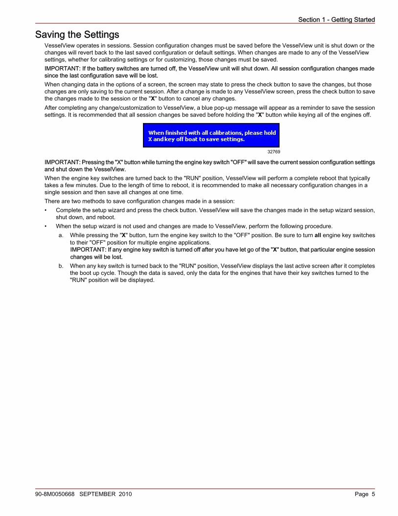
Saving the SettingsVesselView operates in sessions. Session configuration changes must be saved before the VesselView unit is shut down or thechanges will revert back to the last saved configuration or default settings. When changes are made to any of the VesselViewsettings, whether for calibrating settings or for customizing, those changes must be saved.IMPORTANT: If the battery switches are turned off, the VesselView unit will shut down. All session configuration changes madesince the last configuration save will be lost.When changing data in the options of a screen, the screen may state to press the check button to save the changes, but thosechanges are only saving to the current session. After a change is made to any VesselView screen, press the check button to savethe changes made to the session or the "X" button to cancel any changes.After completing any change/customization to VesselView, a blue pop‑up message will appear as a reminder to save the sessionsettings. It is recommended that all session changes be saved before holding the "X" button while keying all of the engines off.
32769
IMPORTANT: Pressing the "X" button while turning the engine key switch "OFF" will save the current session configuration settingsand shut down the VesselView.When the engine key switches are turned back to the "RUN" position, VesselView will perform a complete reboot that typicallytakes a few minutes. Due to the length of time to reboot, it is recommended to make all necessary configuration changes in asingle session and then save all changes at one time.There are two methods to save configuration changes made in a session:• Complete the setup wizard and press the check button. VesselView will save the changes made in the setup wizard session,
shut down, and reboot.• When the setup wizard is not used and changes are made to VesselView, perform the following procedure.
a. While pressing the "X" button, turn the engine key switch to the "OFF" position. Be sure to turn all engine key switchesto their "OFF" position for multiple engine applications.IMPORTANT: If any engine key switch is turned off after you have let go of the "X" button, that particular engine sessionchanges will be lost.
b. When any key switch is turned back to the "RUN" position, VesselView displays the last active screen after it completesthe boot up cycle. Though the data is saved, only the data for the engines that have their key switches turned to the"RUN" position will be displayed.

Section 1 - Getting Started
Notes:
Page 6 90-8M0050668 SEPTEMBER 2010
Section 2 - Setup and Calibration
90-8M0050668 SEPTEMBER 2010 Page 7
Section 2 - Setup and CalibrationTable of ContentsSetup Wizard Overview.......................................................... 8Setup Wizard.......................................................................... 8
Import Configuration (Optional) ...................................... 8Engine Setup........................................................................ 10Display Setup....................................................................... 11Device Setup........................................................................ 12
Device Setup Complete ................................................ 16Calibration Menu Options..................................................... 16Calibrating the Tanks............................................................ 17
Tank and Location Selection ........................................ 17
Tank Calibration ........................................................... 18Method 1: Default .................................................. 18Method 2: Manual .................................................. 18
Tab Setup and Calibration.................................................... 20Calibrating Trim.................................................................... 23
Trim Calibration ............................................................ 23Configuration........................................................................ 24Factory Reset....................................................................... 25Save Configuration............................................................... 26Load Configuration............................................................... 28
2

Section 2 - Setup and Calibration
Page 8 90-8M0050668 SEPTEMBER 2010
Setup Wizard OverviewTurning the key switch to the "RUN" position activates all VesselView units connected to the system. Complete the initial setupprocess using the setup wizard when starting up any VesselView unit for the first time, or after selecting "RESET SETTINGS" onthe "FACTORY RESET" screen. The menu path is: "Main" > "Calibrate" > "Factory Reset." This process calibrates eachVesselView to the vessel's engine, sensor, and instrument configuration. The setup wizard procedures include:• Import configuration—This is used when a configuration is stored onto a USB memory stick.• Engine setup—This is used to define the size, type, and quantity of engines installed on the vessel.• Display setup—This is used to define the screen configuration for your engines.• Device setup—This is used to differentiate each VesselView unit when multiple VesselViews are installed on the vessel.• Tab setup and calibration—This is used to define the number of tabs installed on the vessel and their electrical connection.
Tabs will need to be calibrated so the data displayed is accurate. When configuring tabs and selecting the propulsion type"POD," no calibration is required.
NOTE: Trim is not part of the setup wizard, but requires setup and calibration. Refer to Calibrating Trim.On vessels with multiple VesselViews installed, the configuration setup and calibration settings can be saved onto a USB memorystick and imported onto other VesselView units, rather than repeating the setup procedure manually, or repeat the setup wizardfor each VesselView unit installed. Using the import method requires the unique VesselView ID be manually changed at eachadditional VesselView unit.IMPORTANT: When VesselView is first configured during the setup wizard, the system will automatically detect sensors that arepresent and ignores sensor inputs that have no sensors installed. If a sensor is removed from the system after the initialconfiguration, the VesselView will show faults for the removed sensor. To stop the fault message, perform the "Reset SensorDetection" procedure. Refer to Factory Reset. VesselView will scan for sensors, and because the removed sensor is not installed,the fault message will not appear.
Setup WizardThe VesselView setup wizard guides you through the first steps of configuring the VesselView. The setup wizard begins when theVesselView unit is turned on for the first time or when a factory reset is performed. The VesselView setup wizard starts with theoption to import a saved configuration from a USB memory stick.NOTE: To use a USB memory stick to perform the import function, a VesselView configuration must be previously exported (saved)to the USB memory stick. To skip the "IMPORT CONFIG" option, press the right arrow on the arrow pad. The setup wizard willopen the "ENGINE SETUP" screen. Refer to Save Configuration.1. Turn all engine key switches to the "RUN" position and the "WELCOME" screen will appear.
IMPORTANT: Do not rush VesselView by pressing buttons while the system is booting up to acquire vessel and engine data.When VesselView is initially started or after a factory reset, the system will take a few seconds to complete the boot up process.If you do not see the "IMPORT CONFIG" screen as the next screen, press the left arrow on the arrow pad until it appears.
26695
2. Press the right arrow on the arrow pad to continue to "IMPORT CONFIG."
Import Configuration (Optional)IMPORTANT: The import configuration option is used to import configuration settings that were saved to a USB memory stick.The VesselView unit will recognize USB memory sticks of version 1.1 or 2.0 that is stated to be backwards compatible to version1.1. The VesselView unit will not recognize memory sticks that are only version 2.0 compatible.

Section 2 - Setup and Calibration
90-8M0050668 SEPTEMBER 2010 Page 9
IMPORTANT: Configuration settings saved to a USB memory stick are compiled into one data file. Only one file can exist in theroot of the USB memory stick. VesselView will not recognize multiple import files.1. The "IMPORT CONFIG" screen instructs you to insert a USB memory stick and wait for instructions.
IMPORT CONFIG
TO IMPORT CONFIGURATION, INSERT
MEMORY STICK AND WAIT FOR INSTRUCTIONS.
27304
2. Insert a USB memory stick into the USB port on the back of the VesselView unit.
a - Ethernet port (for future option)b - USB portc - USB memory stick
IMPORTANT: Do not remove the USB memory stick until the import process is complete.3. When the memory stick is detected, the "IMPORT CONFIG" screen will display "MEMORY STICK READY."
IMPORTANT: If you attempt to load a configuration setting that was not saved to the USB memory stick, the import of thedata file will not be successful and a yellow pop‑up message will appear stating "IMPORT UNSUCCESSFUL." If you canrecall the configuration setting that was not saved, select "SKIP" for that particular configuration setting. That particularconfiguration setting will need to be setup and calibrated accordingly.
c
a
b
27329

Section 2 - Setup and Calibration
Page 10 90-8M0050668 SEPTEMBER 2010
4. Press the check button to import the saved configuration.
IMPORT CONFIG
TO IMPORT CONFIGURATION, INSERT
MEMORY STICK AND WAIT FOR INSTRUCTIONS.
MEMORY STICK READY TO IMPORT
27309
5. VesselView will restart and import the configuration.NOTE: If the imported configuration settings are correct for your power package, the setup process is completed. Continue tofinalize the setup of VesselView. Refer to Calibration Menu Options.
Engine SetupVesselView automatically detects the vessel's power package. On the "ENGINE SETUP" screen, you can change the type andnumber of engines. The available power packages are:
• "2 Stroke Gas Outboard"• "4 Stroke Gas Outboard"• "Gas Sterndrive No Troll"• "Gas Inboard No Troll"• "Gas Jet Drive"• "Gas Sterndrive"
• "Gas Inboard"• "Gas Verado"• "Diesel Sterndrive No Troll"• "Diesel Inboard No Troll"• "Diesel Sterndrive"• "Diesel Inboard"
IMPORTANT: If a "Diesel Inboard No Troll" is the identified, VesselView assumes the installed power package is a Zeus driveand will turn on the AutoPilot screens; Pilot, Joystick, Skyhook. All other drive types, the pilot screens must be turned on or off inthe "Settings" option menu.NOTE: VesselView will always default to four engines during the initial setup and after a factory reset.
a - Engine typeb - Number of engines
IMPORTANT: The "ENGINE TYPE" option may be blank when the "ENGINE SETUP" screen initially appears. Before beginningthis procedure, wait until an engine type appears in the "ENGINE TYPE" option, this could take several seconds. If an engine typedoes not appear, check that all engine ignition keys are in the "RUN" position and all VesselView units are properly connected.
b
a
34503
4
Section 2 - Setup and Calibration
90-8M0050668 SEPTEMBER 2010 Page 11
1. Wait until an engine type appears in the "ENGINE TYPE" option. The "ENGINE TYPE" option may take several seconds todetect the engine.NOTE: The VesselView default setting is four engines.
2. If the engine type is correct, proceed to step 5; otherwise, press the check button to access the "ENGINE TYPE" option.3. Press the left or right arrow on the arrow pad to scroll through the available engine types.4. Confirm your selection by pressing the check button.5. If the number of engines is correct, proceed to step 8; otherwise, press the check button, then the down arrow on the arrow
pad to access the "NUMBER OF ENGINES" option.NOTE: Although you may select up to four engines, VesselView displays data for a maximum of three gasoline or dieselengines. Choosing four engines enables you to add two more tanks; and to view the total fuel flow, fuel range, and drive linkgauges for all engines. Some data may not be displayed when a single VesselView is used wtih a triple engine power package.It is recommended that a second VesselView unit be used for a quad engine configuration.
6. Press the right arrow on the arrow pad to increase the number of engines or the left arrow to decrease the number of engines.The maximum number of engines is four.
7. Confirm your selections by pressing the check button.8. Press the right arrow on the arrow pad to continue to the "DISPLAY SETUP" screen.
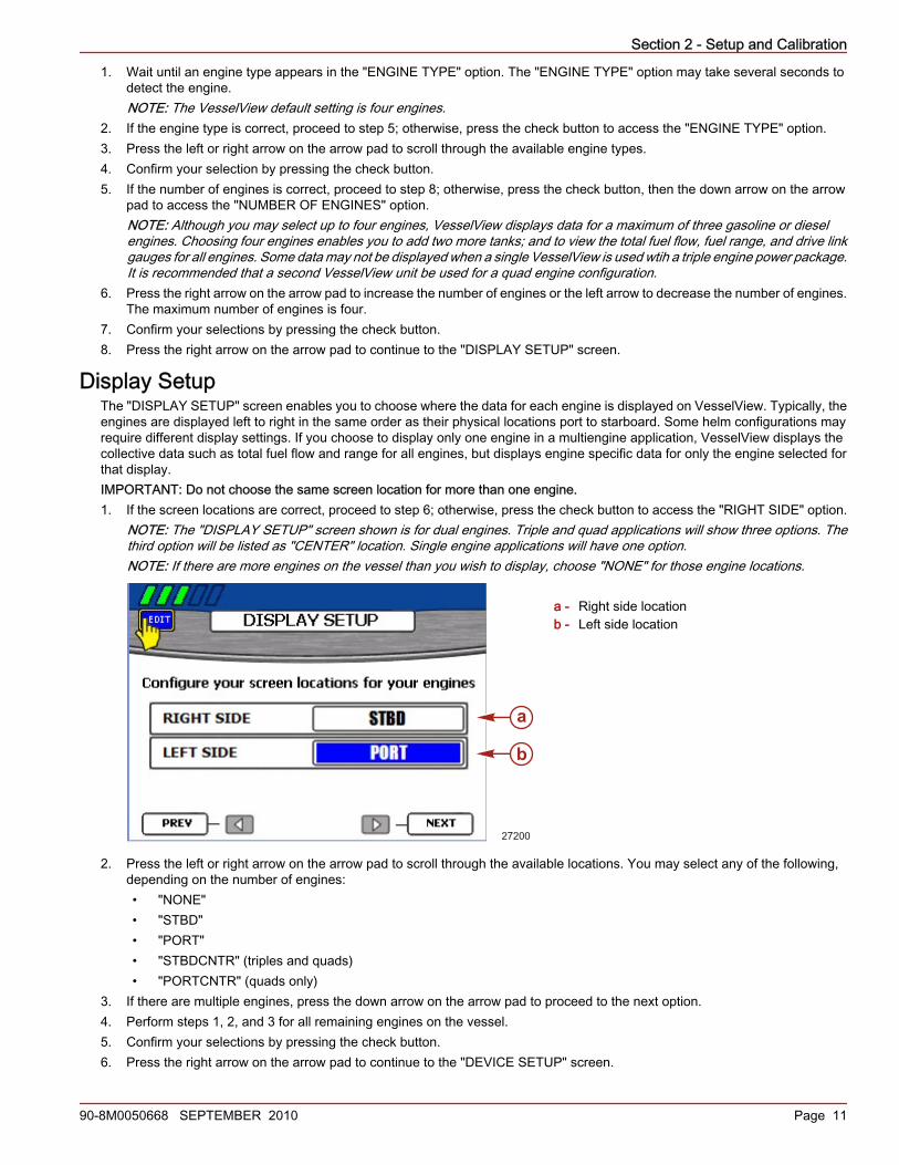
Display SetupThe "DISPLAY SETUP" screen enables you to choose where the data for each engine is displayed on VesselView. Typically, theengines are displayed left to right in the same order as their physical locations port to starboard. Some helm configurations mayrequire different display settings. If you choose to display only one engine in a multiengine application, VesselView displays thecollective data such as total fuel flow and range for all engines, but displays engine specific data for only the engine selected forthat display.IMPORTANT: Do not choose the same screen location for more than one engine.1. If the screen locations are correct, proceed to step 6; otherwise, press the check button to access the "RIGHT SIDE" option.
NOTE: The "DISPLAY SETUP" screen shown is for dual engines. Triple and quad applications will show three options. Thethird option will be listed as "CENTER" location. Single engine applications will have one option.NOTE: If there are more engines on the vessel than you wish to display, choose "NONE" for those engine locations.
a - Right side locationb - Left side location
2. Press the left or right arrow on the arrow pad to scroll through the available locations. You may select any of the following,depending on the number of engines:• "NONE"• "STBD"• "PORT"• "STBDCNTR" (triples and quads)• "PORTCNTR" (quads only)
3. If there are multiple engines, press the down arrow on the arrow pad to proceed to the next option.4. Perform steps 1, 2, and 3 for all remaining engines on the vessel.5. Confirm your selections by pressing the check button.6. Press the right arrow on the arrow pad to continue to the "DEVICE SETUP" screen.
27200
a
b
Section 2 - Setup and Calibration
Page 12 90-8M0050668 SEPTEMBER 2010
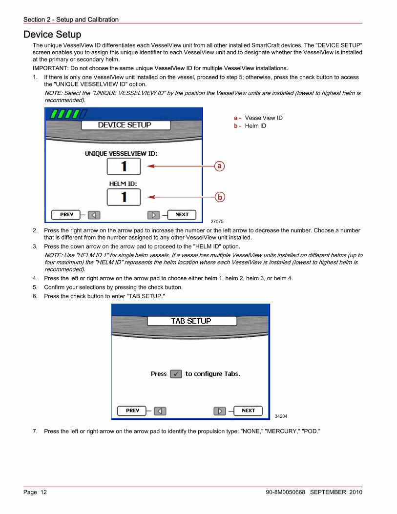
Device SetupThe unique VesselView ID differentiates each VesselView unit from all other installed SmartCraft devices. The "DEVICE SETUP"screen enables you to assign this unique identifier to each VesselView unit and to designate whether the VesselView is installedat the primary or secondary helm.IMPORTANT: Do not choose the same unique VesselView ID for multiple VesselView installations.1. If there is only one VesselView unit installed on the vessel, proceed to step 5; otherwise, press the check button to access
the "UNIQUE VESSELVIEW ID" option.NOTE: Select the "UNIQUE VESSELVIEW ID" by the position the VesselView units are installed (lowest to highest helm isrecommended).
a - VesselView IDb - Helm ID
2. Press the right arrow on the arrow pad to increase the number or the left arrow to decrease the number. Choose a numberthat is different from the number assigned to any other VesselView unit installed.
3. Press the down arrow on the arrow pad to proceed to the "HELM ID" option.NOTE: Use "HELM ID 1" for single helm vessels. If a vessel has multiple VesselView units installed on different helms (up tofour maximum) the "HELM ID" represents the helm location where each VesselView is installed (lowest to highest helm isrecommended).
4. Press the left or right arrow on the arrow pad to choose either helm 1, helm 2, helm 3, or helm 4.5. Confirm your selections by pressing the check button.6. Press the check button to enter "TAB SETUP."
34204
7. Press the left or right arrow on the arrow pad to identify the propulsion type: "NONE," "MERCURY," "POD."
a
b
27075

Section 2 - Setup and Calibration
90-8M0050668 SEPTEMBER 2010 Page 13
NOTE: Calibration of the tabs is not required for Zeus power packages.
PROPULSION TYPE POD
45137
TABS
8. "NONE" is the default selection when no sensors are detected. If tabs are installed, press the down arrow on the arrow padto access the number of tabs. If there are no tabs installed, press the "X" button to go back one step to the "TAB SETUP"screen and continue to step 29.
9. Press the left or right arrow on the arrow pad to select the number of tabs installed. Up to three tabs can be selected.10. Press the down arrow on the arrow pad to access the "RIGHT TAB" window.11. Press the left or right arrow on the arrow pad to select the location name for the right, left, and center tabs. The location names
available are:
Tab location names"NONE" None
"STBD TAB 1" Starboard tab 1"STBD TAB 2" Starboard tab 2"PORT TAB 1" Port tab 1"PORT TAB 2" Port tab 2
"STBD CNTR TAB 1" Starboard center tab 1"STBD CNTR TAB 2" Starboard center tab 2"PORT CNTR TAB 1" Port center tab 1"PORT CNTR TAB 2" Port center tab 2
12. Press the down arrow on the arrow pad to access the "LEFT TAB" window. Press the left or right arrow on the arrow pad toselect the location name for the right, left, and center tabs.
13. Press the down arrow on the arrow pad to access the "CENTER TAB" window. Press the left or right arrow on the arrow padto select the location name for the right, left, and center tabs.
PROPULSION TYPE MERCURY
45138
TABS
NUMBER OF TABS 2RIGHT TAB STBD TAB 1LEFT TAB PORT TAB 2
14. Confirm your selections by pressing the check button.15. Press the "X" button to go back to "TAB SETUP" if corrections are needed.

Section 2 - Setup and Calibration
Page 14 90-8M0050668 SEPTEMBER 2010
16. Press the left or right arrow on the arrow pad to select the tab to be calibrated.
45139
X = DONE CHECK = SELECT
17. Press the check button to begin calibrating the selected tab.18. Lower the selected tab into its down position.19. Press the down or up arrow on the arrow pad to highlight the "ACTUAL DOWN" option.
45140
20. Press the left or right arrow on the arrow pad to adjust the "ACTUAL DOWN" tab percentage to match the "CURRENT ACTUAL%."
21. Raise the tab into its level position.

Section 2 - Setup and Calibration
90-8M0050668 SEPTEMBER 2010 Page 15
22. Press the up arrow on the arrow pad to highlight the "ACTUAL LEVEL" option.
45141
23. Press the left or right arrow on the arrow pad to adjust the "ACTUAL LEVEL" tab percentage to match the "CURRENT ACTUAL%."
24. Raise the tab into its up position.25. Press the up arrow on the arrow pad to highlight the "ACTUAL UP" option.
45142
26. Press the left or right arrow on the arrow pad to adjust the "ACTUAL UP" tab percentage to match the "CURRENT ACTUAL%."
27. Press the check button to save the calibration and go back to the "TAB CALIBRATION" screen.28. If more than one tab exists on the vessel, perform steps 15–27 for the remaining tabs.29. When all the tabs have been calibrated, end the calibration process by selecting the "X" button.
NOTE: After any change or customization to the VesselView configuration, a blue pop‑up message will appear as a reminderto save the session. It is recommended that all session changes be saved before holding the "X" button while keying allengines off. Refer to Section 1 - Saving the Settings.
30. When calibrating the tabs is completed, press the right arrow on the arrow pad to continue to the "COMPLETE" screen.

Section 2 - Setup and Calibration
Page 16 90-8M0050668 SEPTEMBER 2010
Device Setup CompleteThe setup wizard displays the "COMPLETE" screen after you have completed all the steps of the wizard. To review your choicesor to go back to a screen to make corrections, use the left arrow button.
27076
When you are sure that your selections are correct, press the check button to save your configuration and restart the VesselViewunit. VesselView displays a saving settings message, then restarts. The restart process may take a few minutes.NOTE: If you want to change the vessel configuration after exiting the setup wizard, you may either restart the wizard by choosing"RESET SETTINGS" on the "Factory Reset" screen in the "Calibrate" menu or reconfigure the vessel using the "Configuration"menu.
Calibration Menu OptionsThe "Calibrate" menu will allow you to setup your VesselView to your specific boat. The "Calibrate" menu items include thefollowing:• "Tank"• "Tabs"• "Trim"• "Configuration"• "Factory Reset"• "Save Configs"• "Load Configs"
SetupCalibrate
Settings
Alarms
System Info
CalibrateTank
Tabs
Trim
Configuration
Factory Reset
Save Configs
Load Configs
34206
Main
Calibrate
Settings
Alarms
System Info
Favorites

Section 2 - Setup and Calibration
90-8M0050668 SEPTEMBER 2010 Page 17
Calibrating the TanksOpen the "TANK CONFIG" screen by pressing the menu button until the "Main" menu appears. Use the down arrow button toselect the "Calibrate" option. Press the check button to open the "Calibrate" menu, then the check button to select "Tank."
Tank and Location Selection1. Open the "TANK CONFIG" screen. The engine location box is highlighted.2. Use the left or right arrow button to choose which engine to configure.
NOTE: You may configure up to two tanks for each engine on the boat if these engines are so equipped. For example, on atriple‑engine application, six tanks are available.
3. Press the down arrow to proceed to the tank selection box.4. Use the right arrow button to choose which tank number to configure.
a - Engine locationb - Tank selection
5. Press the check button to confirm your choice. The "TYPE," "SIZE," and "LOCATION" boxes will appear.
a - Type of tankb - Size of tankc - Location of tank
6. Use the left or right arrow button to scroll through the available tank types in the "TYPE" box. You may select any of thefollowing:• "NOT USED"• "OIL"• "WASTE"• "FUEL"• "WATER"
7. Press the down arrow to proceed to the "SIZE" box.8. Use the right arrow button to scroll to the capacity of the tank. Holding the button down causes the scroll to speed up.
IMPORTANT: The default unit for measuring tank capacity is U.S. gallons. To choose a different unit of measurement, referto Section 4 ‑ Units.
9. Press the down arrow to proceed to the "LOCATION" box. You may select any of the following:
a
b
27061
a
c
b
27064
Section 2 - Setup and Calibration
Page 18 90-8M0050668 SEPTEMBER 2010
• "S1" (starboard 1), "S2" (starboard 2), "S3" (starboard 3), "SF" (starboard forward), or "SA" (starboard aft)• "P1" (port 1), "P2" (port 2), "P3" (port 3), "PF" (port forward), or "PA" (port aft)• "C1" (center 1), "C2" (center 2), "C3" (center 3), "CF" (center forward), or "CA" (center aft)
10. To change the values already entered, press the "X" button to return to the previous screen. Otherwise, press the check buttonto confirm your selections. VesselView will then display two methods of calibration.
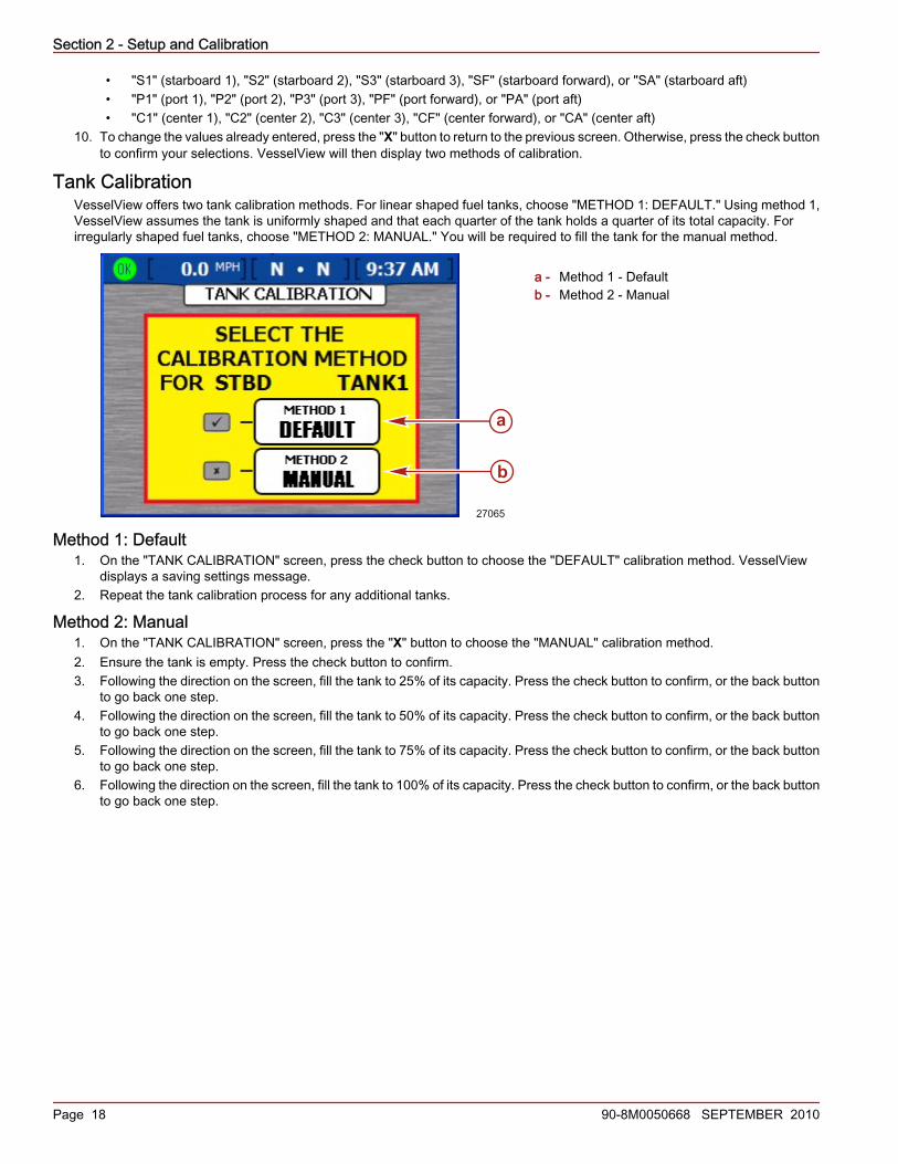
Tank CalibrationVesselView offers two tank calibration methods. For linear shaped fuel tanks, choose "METHOD 1: DEFAULT." Using method 1,VesselView assumes the tank is uniformly shaped and that each quarter of the tank holds a quarter of its total capacity. Forirregularly shaped fuel tanks, choose "METHOD 2: MANUAL." You will be required to fill the tank for the manual method.
a - Method 1 ‑ Defaultb - Method 2 ‑ Manual
Method 1: Default1. On the "TANK CALIBRATION" screen, press the check button to choose the "DEFAULT" calibration method. VesselView
displays a saving settings message.2. Repeat the tank calibration process for any additional tanks.
Method 2: Manual1. On the "TANK CALIBRATION" screen, press the "X" button to choose the "MANUAL" calibration method.2. Ensure the tank is empty. Press the check button to confirm.3. Following the direction on the screen, fill the tank to 25% of its capacity. Press the check button to confirm, or the back button
to go back one step.4. Following the direction on the screen, fill the tank to 50% of its capacity. Press the check button to confirm, or the back button
to go back one step.5. Following the direction on the screen, fill the tank to 75% of its capacity. Press the check button to confirm, or the back button
to go back one step.6. Following the direction on the screen, fill the tank to 100% of its capacity. Press the check button to confirm, or the back button
to go back one step.
a
b
27065

Section 2 - Setup and Calibration
90-8M0050668 SEPTEMBER 2010 Page 19
7. VesselView will display the saving settings message and return you to the beginning of "TANK CONFIG." Repeat the tankcalibration process for any additional tanks.
a - Empty tankb - Fill to 25% fullc - Fill to 50% fulld - Fill to 75% fulle - Fill to 100% fullf - Saving settings message
a b
c d
27066
e f
Section 2 - Setup and Calibration
Page 20 90-8M0050668 SEPTEMBER 2010
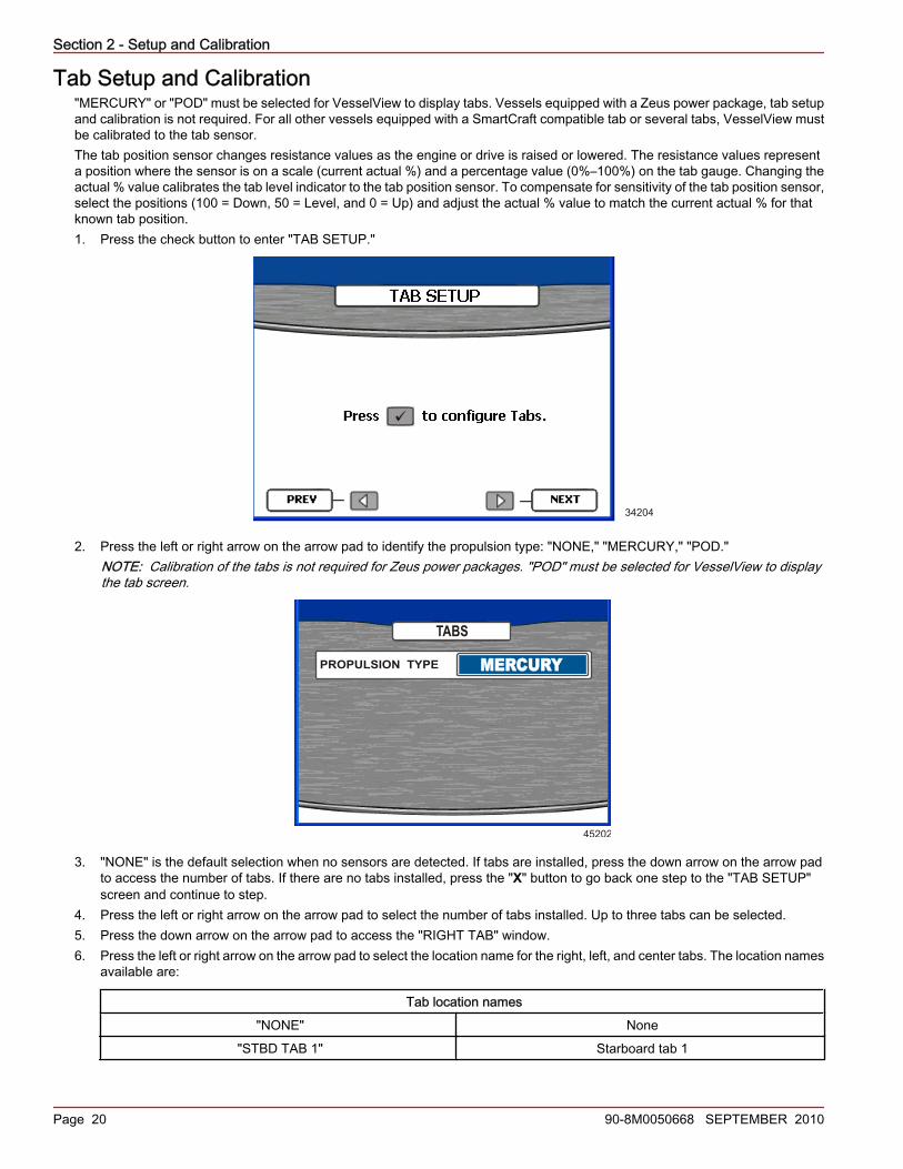
Tab Setup and Calibration"MERCURY" or "POD" must be selected for VesselView to display tabs. Vessels equipped with a Zeus power package, tab setupand calibration is not required. For all other vessels equipped with a SmartCraft compatible tab or several tabs, VesselView mustbe calibrated to the tab sensor.The tab position sensor changes resistance values as the engine or drive is raised or lowered. The resistance values representa position where the sensor is on a scale (current actual %) and a percentage value (0%–100%) on the tab gauge. Changing theactual % value calibrates the tab level indicator to the tab position sensor. To compensate for sensitivity of the tab position sensor,select the positions (100 = Down, 50 = Level, and 0 = Up) and adjust the actual % value to match the current actual % for thatknown tab position.1. Press the check button to enter "TAB SETUP."
34204
2. Press the left or right arrow on the arrow pad to identify the propulsion type: "NONE," "MERCURY," "POD."NOTE: Calibration of the tabs is not required for Zeus power packages. "POD" must be selected for VesselView to displaythe tab screen.
PROPULSION TYPE MERCURY
45202
TABS
3. "NONE" is the default selection when no sensors are detected. If tabs are installed, press the down arrow on the arrow padto access the number of tabs. If there are no tabs installed, press the "X" button to go back one step to the "TAB SETUP"screen and continue to step.
4. Press the left or right arrow on the arrow pad to select the number of tabs installed. Up to three tabs can be selected.5. Press the down arrow on the arrow pad to access the "RIGHT TAB" window.6. Press the left or right arrow on the arrow pad to select the location name for the right, left, and center tabs. The location names
available are:
Tab location names"NONE" None
"STBD TAB 1" Starboard tab 1

Section 2 - Setup and Calibration
90-8M0050668 SEPTEMBER 2010 Page 21
Tab location names"STBD TAB 2" Starboard tab 2"PORT TAB 1" Port tab 1"PORT TAB 2" Port tab 2
"STBD CNTR TAB 1" Starboard center tab 1"STBD CNTR TAB 2" Starboard center tab 2"PORT CNTR TAB 1" Port center tab 1"PORT CNTR TAB 2" Port center tab 2
7. Press the down arrow on the arrow pad to access the "LEFT TAB" window. Press the left or right arrow on the arrow pad toselect the location name for the right, left, and center tabs.
8. Press the down arrow on the arrow pad to access the "CENTER TAB" window. Press the left or right arrow on the arrow padto select the location name for the right, left, and center tabs.
PROPULSION TYPE MERCURY
45138
TABS
NUMBER OF TABS 2RIGHT TAB STBD TAB 1LEFT TAB PORT TAB 2
9. Confirm your selections by pressing the check button.10. Press the "X" button to go back to "TAB SETUP" if corrections are needed.11. Press the left or right arrow on the arrow pad to select the tab to be calibrated.
45139
X = DONE CHECK = SELECT
12. Press the check button to begin calibrating the selected tab.13. Lower the selected tab into its down position.
Section 2 - Setup and Calibration
Page 22 90-8M0050668 SEPTEMBER 2010
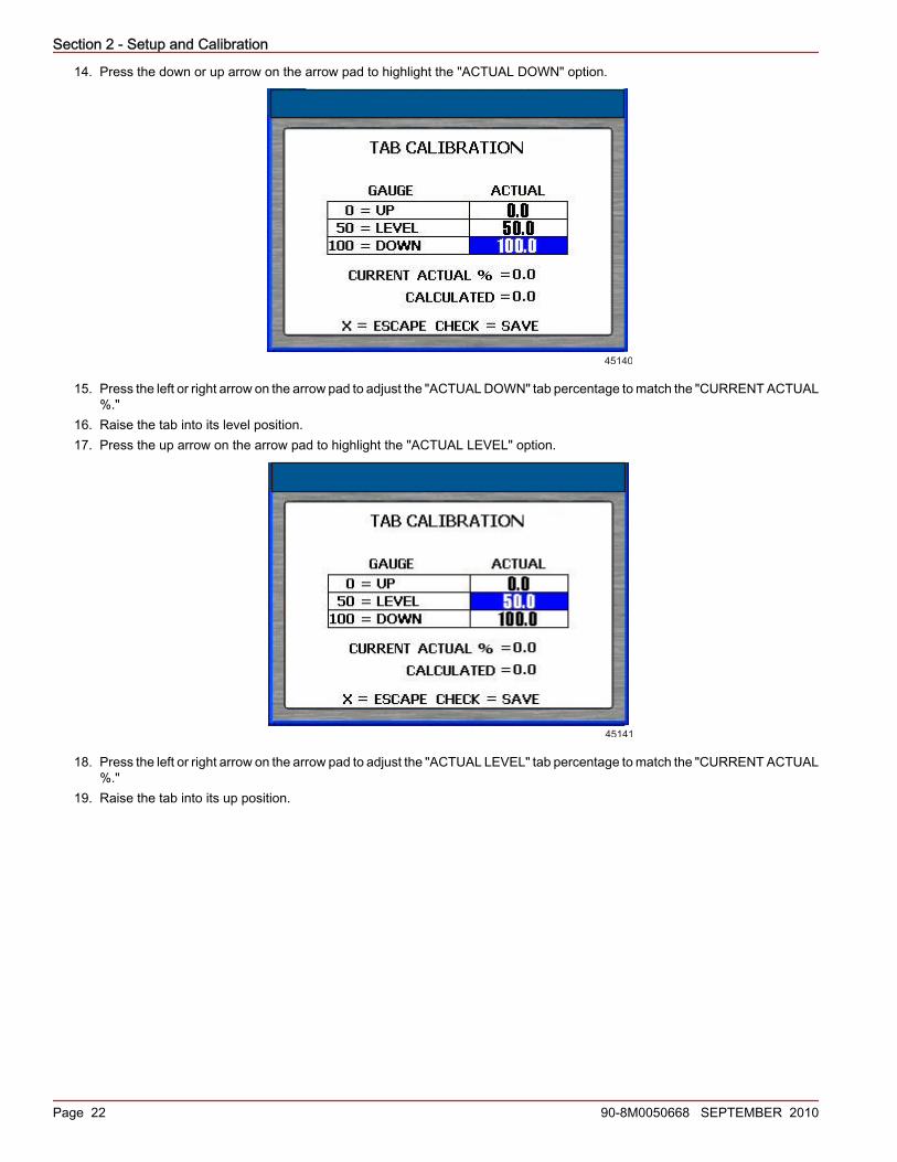
14. Press the down or up arrow on the arrow pad to highlight the "ACTUAL DOWN" option.
45140
15. Press the left or right arrow on the arrow pad to adjust the "ACTUAL DOWN" tab percentage to match the "CURRENT ACTUAL%."
16. Raise the tab into its level position.17. Press the up arrow on the arrow pad to highlight the "ACTUAL LEVEL" option.
45141
18. Press the left or right arrow on the arrow pad to adjust the "ACTUAL LEVEL" tab percentage to match the "CURRENT ACTUAL%."
19. Raise the tab into its up position.

Section 2 - Setup and Calibration
90-8M0050668 SEPTEMBER 2010 Page 23
20. Press the up arrow on the arrow pad to highlight the "ACTUAL UP" option.
45142
21. Press the left or right arrow on the arrow pad to adjust the "ACTUAL UP" tab percentage to match the "CURRENT ACTUAL%."
22. Press the check button to save the calibration and go back to the "TAB CALIBRATION" screen.23. If more than one tab exists on the vessel, perform steps 10–22 for the remaining tabs.24. When all the tabs have been calibrated, end the calibration process by selecting the "X" button.
NOTE: After any change or customization to the VesselView configuration, a blue pop‑up message will appear as a reminderto save the session. It is recommended that all session changes be saved before holding the "X" button while keying allengines off. Refer to Section 1 - Saving the Settings.
25. When calibrating the tabs is completed, press the right arrow on the arrow pad to continue to the "COMPLETE" screen.
Calibrating TrimFor power packages with trim, configure the trim settings on the "TRIM CALIBRATION" screen. VesselView does not display the"TRIM CALIBRATION" screen for power packages without trim. To open the "TRIM CALIBRATION" screen, press the menu buttonuntil the "Main" menu appears, then use the down arrow button to select the "Calibrate" option. Press the check button to openthe "Calibrate" menu. Press the down arrow button, then the check button to select "Trim."NOTE: Trim calibration does not set the maximum engine trim and trailer limits. Refer to the engine installation manual for moreinformation on your specific engine.
Trim Calibration1. Open the "TRIM CALIBRATION" screen.2. The "TRIM ENGINE" box prompts you to trim all engines or drives "DOWN."
27204

Section 2 - Setup and Calibration
Page 24 90-8M0050668 SEPTEMBER 2010
3. Press the check button to confirm that you have trimmed all engines or drives to the full down position, or press the "X" buttonto go back one step. This sets the "0.0" trim setting.
4. When the "TRIM ENGINE" box prompts you to trim "UP," trim all engines or drives up, but not to the trailer position. This willdisplay a "10.0" trim setting.
27206
5. Press the check button to confirm that you have trimmed all engines or drives up to the "10.0" position, or press the "X" buttonto go back one step.
6. When the "TRIM ENGINE" box prompts you to trim to "MAX," trim all engines or drives all the way up to the trailer position.This will display a "25.0" trim setting.
27207
7. Press the check button to confirm that you have trimmed all engines or drives to the trailer position, or press the "X" buttonto go back one step. VesselView will display the saving settings screen and restart.NOTE: After any change or customization to the VesselView configuration, a blue pop‑up message will appear as a reminderto save the session. It is recommended that all session changes be saved before holding the "X" button while keying allengines off. Refer to Section 1 - Saving the Settings.
ConfigurationNOTE: A configuration of the vessel does not need to be performed if the vessel has been configured using the setup wizard.

Section 2 - Setup and Calibration
90-8M0050668 SEPTEMBER 2010 Page 25
A vessel configuration is used to assign the VesselView its location on the vessel. It also allows you to select the number of engineson the vessel and where the engine data should be displayed. To begin vessel configuration, press the menu button until the"Main" menu appears, then use the down arrow button to select the "Calibrate" option. Press the check button to open the"Calibrate" menu, then use the down arrow to select "Configuration." Press the check button to open the vessel configurationscreen.
a - Power package nameb - "HELM ID"—Identifies the helm location
of the VesselViewc - "DEVICE ID"—Unique identifier for the
VesselView unitd - "NUM ENGINES"—Number of enginese - "RIGHT SCREEN"—Engine data
displayed on the right side of the screenf - "LEFT SCREEN"—Engine data
displayed on the left side of the screen(multiple engines only)
g - "CENTER SCREEN"—Engine datadisplayed on the center of the screen(triple and quad engines only)
NOTE: The power package can only be changed in the setup wizard. Perform a factory reset to change the power package andgo to the setup wizard. Refer to Factory Reset.1. Use the right and left arrow buttons to select the "HELM ID" number.2. Press the down arrow button to proceed to "DEVICE ID."3. Use the right and left arrow buttons to select the device identification number.4. Press the down arrow button to proceed to "NUM ENGINES."5. Use the right and left arrow buttons to select the number of engines.6. Press the down arrow button to proceed to "RIGHT SCREEN."7. Press the left or right arrow button to scroll through the available location types. You may select any of the following, depending
on the number of engines:• "NONE"• "STBD"• "PORT"• "CENTER" (triple only)• "STBDCNTR" (quads only)• "PORTCNTR" (quads only)
8. If there are multiple engines, press the down arrow to proceed to the "LEFT SCREEN."9. Press the left or right arrow button to scroll through the available location types.10. For three or four engine applications, press the down arrow to proceed to "CENTER SCREEN."11. Confirm your selections by pressing the check button.12. VesselView will display the saving settings screen and restart.
Factory ResetThe "FACTORY RESET" menu is used to reset all VesselView settings to factory default or to perform a sensor detection. Toperform a factory reset, press the menu button until the "Main" menu appears, then use the down arrow button to select the"Calibrate" menu. Press the check button to open the "Calibrate" menu, then use the down arrow to select "Factory Reset." Pressthe check button to open the "FACTORY RESET" screen.IMPORTANT: By selecting "RESET SETTINGS" all vessel data settings will be lost.1. The "FACTORY RESET" screen will ask you to "CHOOSE RESET TYPE." The two types of resets are:
• "RESET SETTINGS"—This will reset VesselView to factory defaults• "RESET SENSOR DETECTION"—This will scan the VesselView network for any recently removed or installed sensors
2. Use the left and right arrow buttons to select between the two types.
a
b
c
d
e
f
g34244
Section 2 - Setup and Calibration
Page 26 90-8M0050668 SEPTEMBER 2010
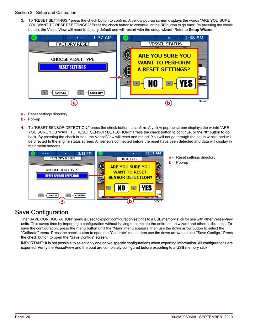
3. To "RESET SETTINGS," press the check button to confirm. A yellow pop‑up screen displays the words "ARE YOU SUREYOU WANT TO RESET SETTINGS?" Press the check button to continue, or the "X" button to go back. By pressing the checkbutton, the VesselView will reset to factory default and will restart with the setup wizard. Refer to Setup Wizard.
a - Reset settings directoryb - Pop‑up
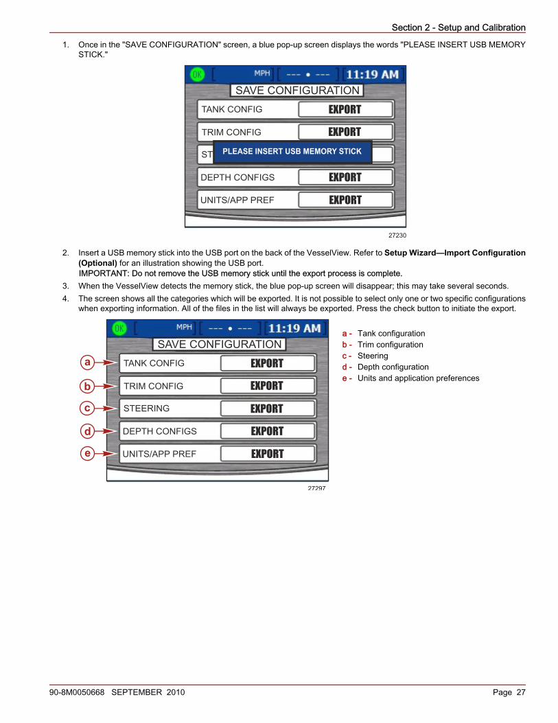
4. To "RESET SENSOR DETECTION," press the check button to confirm. A yellow pop‑up screen displays the words "AREYOU SURE YOU WANT TO RESET SENSOR DETECTION?" Press the check button to continue, or the "X" button to goback. By pressing the check button, the VesselView will reset and restart. You will not go through the setup wizard and willbe directed to the engine status screen. All sensors connected before the reset have been detected and data will display intheir menu screens.
a - Reset settings directoryb - Pop‑up
Save ConfigurationThe "SAVE CONFIGURATION" menu is used to export configuration settings to a USB memory stick for use with other VesselViewunits. This saves time by importing a configuration without having to complete the entire setup wizard and other calibrations. Tosave the configuration, press the menu button until the "Main" menu appears, then use the down arrow button to select the"Calibrate" menu. Press the check button to open the "Calibrate" menu, then use the down arrow to select "Save Configs." Pressthe check button to open the "Save Configs" screen.IMPORTANT: It is not possible to select only one or two specific configurations when exporting information. All configurations areexported. Verify the VesselView and the boat are completely configured before exporting to a USB memory stick.
34245a b
a b 38507
Section 2 - Setup and Calibration
90-8M0050668 SEPTEMBER 2010 Page 27
1. Once in the "SAVE CONFIGURATION" screen, a blue pop‑up screen displays the words "PLEASE INSERT USB MEMORYSTICK."
SAVE CONFIGURATION
TANK CONFIG
TRIM CONFIG
DEPTH CONFIGS
UNITS/APP PREF
STEERING
EXPORT
EXPORT
EXPORT
EXPORT
EXPORT
PLEASE INSERT USB MEMORY STICK
27230
2. Insert a USB memory stick into the USB port on the back of the VesselView. Refer to Setup Wizard—Import Configuration(Optional) for an illustration showing the USB port.IMPORTANT: Do not remove the USB memory stick until the export process is complete.
3. When the VesselView detects the memory stick, the blue pop‑up screen will disappear; this may take several seconds.4. The screen shows all the categories which will be exported. It is not possible to select only one or two specific configurations
when exporting information. All of the files in the list will always be exported. Press the check button to initiate the export.
a - Tank configurationb - Trim configurationc - Steeringd - Depth configuratione - Units and application preferences
SAVE CONFIGURATION
TANK CONFIG
TRIM CONFIG
DEPTH CONFIGS
UNITS/APP PREF
STEERING
EXPORT
EXPORT
EXPORT
EXPORT
EXPORT
a
b
c
d
e
27297

Section 2 - Setup and Calibration
Page 28 90-8M0050668 SEPTEMBER 2010
5. When the export is complete, a blue pop‑up screen displays the words "EXPORT COMPLETE." Press the "X" button to exit.
EXPORT COMPLETE
PRESS (X) TO CONTINUE
27292
6. It is now safe to remove the USB memory stick.
Load ConfigurationThe "LOAD CONFIGURATION" menu imports the configuration settings saved to a USB memory stick from another VesselViewunit. To "Load Configs," press the menu button until the "Main" menu appears, then use the down arrow button to select the"Calibrate" menu. Press the check button to open the "Calibrate" menu, then use the down arrow to select "Load Configs." Pressthe check button to open the "Load Configs" screen.1. Once in the "LOAD CONFIGURATION" screen, a blue pop‑up screen displays the words "PLEASE INSERT USB MEMORY
STICK."
LOAD CONFIGURATION
TANK CONFIG
TRIM CONFIG
DEPTH CONFIGS
UNITS/APP PREF
STEERING
IMPORT
IMPORT
EXPORT
IMPORT
IMPORT
PLEASE INSERT USB MEMORY STICK
27232
2. Insert a USB memory stick into the USB port on the back of the VesselView. Refer to Setup Wizard—Import Configuration(Optional) for an illustration showing the USB port.IMPORTANT: Do not remove the USB memory stick until the import process is complete.
3. When the VesselView detects the memory stick, the blue pop‑up screen will disappear; this may take several seconds.

Section 2 - Setup and Calibration
90-8M0050668 SEPTEMBER 2010 Page 29
4. The screen shows the configuration categories. Select either "IMPORT" or "SKIP" using the left and right arrow buttons.
a - Tank configurationb - Trim configurationc - Steeringd - Depth configuratione - Units and application preferences
5. Press the down arrow button to proceed to the next configuration category. Select either "IMPORT" or "SKIP" for each of thecategories.
IMPORT CONFIG
TO IMPORT CONFIGURATION, INSERT
MEMORY STICK AND WAIT FOR INSTRUCTIONS.
MEMORY STICK READY TO IMPORT
27309
6. Press the check button to save the selected configurations. The VesselView will restart and finish loading the configuration.
LOAD CONFIGURATION
TANK CONFIG
TRIM CONFIG
DEPTH CONFIGS
UNITS/APP PREF
STEERING
IMPORT
IMPORT
IMPORT
IMPORT
IMPORT
b
c
d
e
a
27293

Section 2 - Setup and Calibration
Notes:
Page 30 90-8M0050668 SEPTEMBER 2010

Section 3 - Screen Overview and Operation
90-8M0050668 SEPTEMBER 2010 Page 31
Section 3 - Screen Overview and OperationTable of ContentsIdentifying and Using Screen Categories............................. 32Available VesselView Display Screens ............................... 32
MerCruiser Display Screens ......................................... 33Outboard and Jet Drive Display Screens ..................... 34
VesselView Display Screens................................................ 34Propulsion ..................................................................... 34Vessel ........................................................................... 37Environment and Navigation ........................................ 38
VesselView Setup Screens.................................................. 40Calibrate ....................................................................... 40Settings ......................................................................... 41
Alarms .......................................................................... 44System Info ................................................................... 44
Checking Status Using the Status Bar................................. 44Fault Icons .................................................................... 45Fuel Alarms .................................................................. 46
Using the Menu Panel.......................................................... 47Navigating Through the Screens .................................. 48
Using Pop‑Up Windows........................................................ 49Alarms and Faults ......................................................... 49Screen Brightness ........................................................ 49
3

Section 3 - Screen Overview and Operation
Page 32 90-8M0050668 SEPTEMBER 2010
Identifying and Using Screen CategoriesVesselView displays engine, vessel, environmental, navigation, and calibration data through various screens. These screens aregrouped into four categories:• Propulsion contains all screens related to propulsion, trim, tabs, and engine performance.• Vessel contains all screens related to fuel use, tank levels, and other items such as generators.• Environment and Navigation contains all screens related to depth, navigation, and GPS.• Setup contains all screens related to setting up and calibrating the systems connected to the VesselView.
There are two ways to view the pages in a category:1. Use the propulsion, vessel, or environment and navigation button to view screens in each screen category.
a. Press the button that corresponds to the screen category you wish to view. Refer to Section 1 - Keypad Functions.b. Use the right arrow button or the propulsion, vessel, or environment and navigation button to advance to the next page
in the category. Use the left arrow button to move back a page.2. Use the menu button to view screens in the propulsion, vessel, environment and navigation, or setup screen categories.
a. Press the menu button to access a list of propulsion, vessel, or environment and navigation screens. The list will pop‑upon the right side of the screen.
b. To view each screen category while in the menu screen, press the desired propulsion, vessel, or environment andnavigation button. This will list each screen display name in the selected screen category.
c. Use the up or down arrow button to select a screen to view. Once you have highlighted a screen display name, pressthe check button to view the screen. To go back to the screen display list, press the menu button.
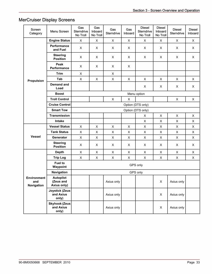
Available VesselView Display ScreensThe following charts show the available screens for MerCruiser, CMD, Outboard, and Jet Drive engines. The default screens areidentified with an "X." Depending on the power package and the installed sensors, the display screens without an "X" can bemanually turned on. The menu path is: "Main" > "Settings" > "Screen Options."
Section 3 - Screen Overview and Operation
90-8M0050668 SEPTEMBER 2010 Page 33
MerCruiser Display Screens
ScreenCategory Menu Screen
GasSterndriveNo Troll
GasInboardNo Troll
GasSterndrive
GasInboard
DieselSterndriveNo Troll
DieselInboardNo Troll
DieselSterndrive
DieselInboard
Propulsion
Engine Status X X X X X X X XPerformance
and Fuel X X X X X X X X
SteeringPosition X X X X X X X X
PeakPerformance X X X X
Trim X XTab X X X X X X X X
Demand andLoad X X X X
Boost Menu optionTroll Control X X X X
Cruise Control Option (DTS only)Smart Tow Option (DTS only)
Transmission X X X XIntake X X X X
Vessel
Vessel Status X X X X X X X XTank Status X X X X X X X XGenerator X X X X X X X XSteeringPosition X X X X X X X X
Environmentand
Navigation
Depth X X X X X X X XTrip Log X X X X X X X XFuel to
Waypoint GPS only
Navigation GPS onlyAutopilot(Zeus and
Axius only)Axius only X Axius only
Joystick (Zeusand Axius
only)Axius only X Axius only
Skyhook (Zeusand Axius
only)Axius only X Axius only

Section 3 - Screen Overview and Operation
Page 34 90-8M0050668 SEPTEMBER 2010
Outboard and Jet Drive Display Screens
Screen Category Menu Screen 2‑Stroke GasOutboard
4‑Stroke GasOutboard Gas Jet Drive Gas Verado
Propulsion
Engine Status X X X XPerformance and
Fuel X X X X
PeakPerformance X X X X
Trim X X XTab X X X X
Boost Menu option (Verado only)Troll Control X X X X
Cruise Control Option (DTS only)Smart Tow Option (DTS only)
Vessel
Vessel Status X X X XTank Status X X X XGenerator X X X X
Environment andNavigation
Depth X X X XTrip Log X X X X
Fuel to Waypoint GPS onlyNavigation GPS only
VesselView Display ScreensNOTE: The screens listed in the following charts may vary depending on engine type and number of engines. Refer to AvailableVesselView Display Screens.
PropulsionScreen Display
Name Description Screen
Engine Status Displays engine RPM and shows various engine datadepending on the engine type.
27210
Performance andFuel
Displays engine RPM, speed, fuel tank levels, total fuel used,and estimated fuel range.
27211

Section 3 - Screen Overview and Operation
90-8M0050668 SEPTEMBER 2010 Page 35
Screen DisplayName Description Screen
Steering PositionDisplays steering position, gear position, speed over ground,bearing to waypoint, wind speed, wind direction, water depth,
and boat speed.
MPHSOG23.5
STEERING ANGLE
DEPTH
SPEED
22.9MPH
GPS10.445177
FT
Peak Performance Displays engine RPM and speed, along with the peak RPM andspeed.
27212
Trim Displays engine RPM, speed, gallons per hour, and trim level.
27213
Tab Displays engine RPM, speed, gallons per hour, and the positionof the tabs (Zeus and inboard applications only).
34267
Demand and Load Displays engine RPM, load, and throttle percentages.
27115
Section 3 - Screen Overview and Operation
Page 36 90-8M0050668 SEPTEMBER 2010
Screen DisplayName Description Screen
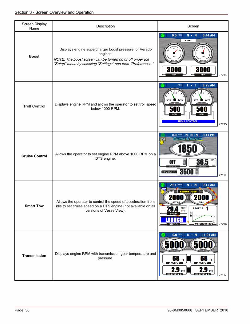
Boost
Displays engine supercharger boost pressure for Veradoengines.
NOTE: The boost screen can be turned on or off under the"Setup" menu by selecting "Settings" and then "Preferences."
27214
Troll Control Displays engine RPM and allows the operator to set troll speedbelow 1000 RPM.
27215
Cruise Control Allows the operator to set engine RPM above 1000 RPM on aDTS engine.
27119
Smart TowAllows the operator to control the speed of acceleration fromidle to set cruise speed on a DTS engine (not available on all
versions of VesselView).
27216
Transmission Displays engine RPM with transmission gear temperature andpressure.
27117
Section 3 - Screen Overview and Operation
90-8M0050668 SEPTEMBER 2010 Page 37
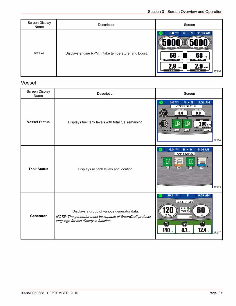
Screen DisplayName Description Screen
Intake Displays engine RPM, intake temperature, and boost.
27116
VesselScreen Display
Name Description Screen
Vessel Status Displays fuel tank levels with total fuel remaining.
27114
Tank Status Displays all tank levels and location.
27113
GeneratorDisplays a group of various generator data.
NOTE: The generator must be capable of SmartCraft protocollanguage for this display to function.
120 60
140 8.7 12.4F PSI Vo27217

Section 3 - Screen Overview and Operation
Page 38 90-8M0050668 SEPTEMBER 2010
Screen DisplayName Description Screen
Steering PositionDisplays steering position, gear position, speed over ground,
bearing to waypoint, wind speed, wind direction, water depth, andboat speed.
MPHSOG23.5
STEERING ANGLE
DEPTH
SPEED
22.9MPH
GPS10.445177
FT
Environment and NavigationScreen Display
Name Description Screen
DepthDisplays water depth, speed through the available sensor, watertemperature, and allows the operator to change the depth alarm
limits.
27218
Trip Log Displays total trip time, average speed, distance, and fuel usagedata.
27220
Fuel toWaypoint Displays fuel usage data to a specified waypoint.
27110
Section 3 - Screen Overview and Operation
90-8M0050668 SEPTEMBER 2010 Page 39
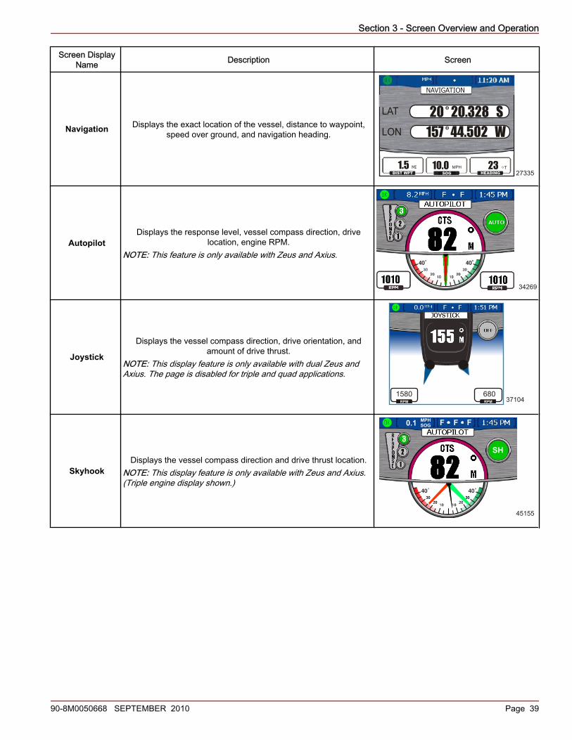
Screen DisplayName Description Screen
Navigation Displays the exact location of the vessel, distance to waypoint,speed over ground, and navigation heading.
LAT
LON
DIST WPT SOG HEADING1.5 10.0 23MI MPH TO
NAVIGATION
20 20.328 S157 44.502 W
o
o
27335
AutopilotDisplays the response level, vessel compass direction, drive
location, engine RPM.NOTE: This feature is only available with Zeus and Axius.
34269
Joystick
Displays the vessel compass direction, drive orientation, andamount of drive thrust.
NOTE: This display feature is only available with dual Zeus andAxius. The page is disabled for triple and quad applications.
1580RPM
680RPM 37104
SkyhookDisplays the vessel compass direction and drive thrust location.
NOTE: This display feature is only available with Zeus and Axius.(Triple engine display shown.)
SH
0.1 MPHSOG FF F
45155
Section 3 - Screen Overview and Operation
Page 40 90-8M0050668 SEPTEMBER 2010
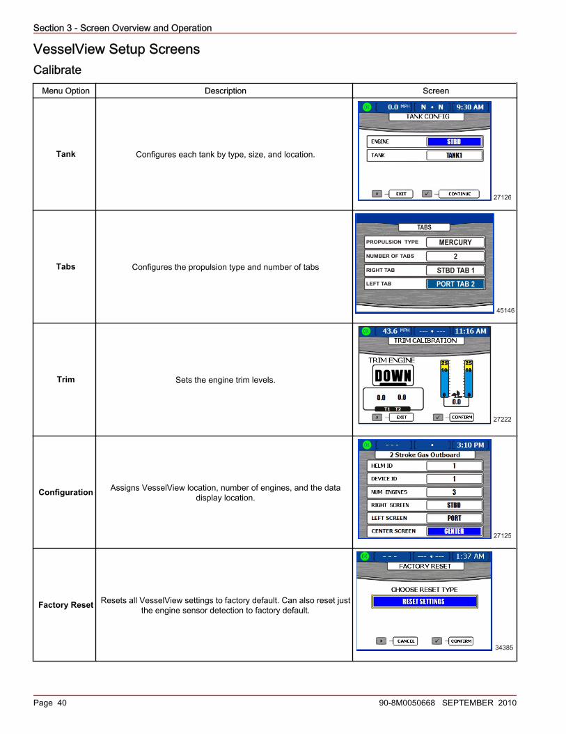
VesselView Setup ScreensCalibrate
Menu Option Description Screen
Tank Configures each tank by type, size, and location.
27126
Tabs Configures the propulsion type and number of tabs
PROPULSION TYPE MERCURY
45146
TABS
NUMBER OF TABS 2RIGHT TAB STBD TAB 1LEFT TAB PORT TAB 2
Trim Sets the engine trim levels.
27222
Configuration Assigns VesselView location, number of engines, and the datadisplay location.
27125
Factory Reset Resets all VesselView settings to factory default. Can also reset justthe engine sensor detection to factory default.
34385

Section 3 - Screen Overview and Operation
90-8M0050668 SEPTEMBER 2010 Page 41
Menu Option Description Screen
Save Configs Used to save selected configuration data to a memory stick.
SAVE CONFIGURATION
TANK CONFIG
TRIM CONFIG
DEPTH CONFIGS
UNITS/APP PREF
STEERING
EXPORT
EXPORT
EXPORT
EXPORT
EXPORT
27235
Load Configs Used to load configuration data through a memory stick.
LOAD CONFIGURATION
TANK CONFIG
TRIM CONFIG
DEPTH CONFIGS
UNITS/APP PREF
STEERING
IMPORT
IMPORT
IMPORT
IMPORT
IMPORT
27234
SettingsMenu Option Description Screen
Screen Options >Status Bar Sets the status bar info at the top of every display screen.
27121
Screen Options >Steering
Sets the type of data to display at the bottom of the steeringposition screen in the vessel menu, and is also used to zero a
rudder sensor angle.
STEERING
LEFT DATA AREA
RIGHT DATA AREA
STEERING OFFSET 0
WATER DEPTH
BOAT SPEEDO
34568
Pages On/OffEnables the user to specifiy what screens in each of the threecategories are turned on or off and which screens they want
quick access to.
37063

Section 3 - Screen Overview and Operation
Page 42 90-8M0050668 SEPTEMBER 2010
Menu Option Description Screen
Trim Settings Turns the trim pop‑up window on or off, sets the amount of timethe pop‑up remains on the screen and adjusts the trim filter.
37067
TRIM SETTINGTRIM POPUP
POPUP TIME
TRIM DELTA %
ON
2 sec
0.5
Tab Settings Changes the number of tabs available and changes the type andlocation of the tab.
PROPULSION TYPE MERCURY
45146
TABS
NUMBER OF TABS 2RIGHT TAB STBD TAB 1LEFT TAB PORT TAB 2
Autopilot Config Turns the autopilot screens on or off.
37070
Clock/Light Sets the clock time and the brightness of the screen.
27120
Preferences Sets the pop‑up warnings, GPS refresh rate, favorites time, andsteering sensor option.
45158
INVERT STEERING NO
POP-UP WARNINGS YES
GPS SPD REFRESH LOW
FAVORITES TIME 5

Section 3 - Screen Overview and Operation
90-8M0050668 SEPTEMBER 2010 Page 43
Menu Option Description Screen
Boat SpeedSets the type of speed source as GPS or pitot sensor
("STRATEGY"), adjust the pitot multiplier, paddle frequency,transition speed.
BOAT SPEED
45160
SOURCE
PITOT SENSOR
PITOT MULT
PADDLE FREQ
TRANSITION SPD
STRATEGY
100 PSI
1.00
4.90Hz/MI
25.0MPH
Warnings Turns the warning horn on or off and sets the fuel level alarm.
27123
Units Sets unit of speed, depth, distance, temperature, and pressure.
27223
Units 2 Sets units of volume and fuel flow.
27224
Offsets Sets offset for depth, tank, sea temperature, and steering.
34302
STEERING OFFSET 0O

Section 3 - Screen Overview and Operation
Page 44 90-8M0050668 SEPTEMBER 2010
AlarmsMenu Option Description Screen
Active Alarms Displays active alarms.
34515
STBD
STBD
STBD
STBD
Alarm History Displays alarms in the history.
34516
STBD
STBD
STBD
STBD
STBD
System InfoMenu Option Description Screen
Software Info Displays the VesselView software version and other data.
27426
Hardware Info Displays VesselView hardware information.
27427
Checking Status Using the Status BarVesselView displays important information in the status bar at the top of each screen. The status bar displays up to four differenticons and messages. Notices of conditions that may need attention (such as warnings, fuel level alerts, and faults) appear as anicon on the left side of the status bar. The fault text will temporarily replace the status bar icons until the fault is cleared. If morethan one fault has occurred, the faults will appear one after the other in the sequence they occurred. To clear a fault messagefrom the status bar after the fault has been corrected, press the "X" button.

Section 3 - Screen Overview and Operation
90-8M0050668 SEPTEMBER 2010 Page 45
Status information such as time, speed, air temperature, and fuel consumption for example, can appear in either of three dataoptions. The data in these options can be arranged under the "Main" menu by selecting "Settings" > "Screen Options" > "Statusbar." Refer to Section 4 - Status Bar Options.NOTE: When "Diesel Inboard No Troll" is the power package installed, starboard and port tab status bar selection is not available.
a - Fault iconb - Left data boxc - Center data boxd - Right data box
• The following is a list of data options available in the status bar. Depending on the power package installation, some of theseoptions may not be available.
Time
Speed
Speed Over Ground ("SPD OVR GND")
Sea Temperature ("SEA TEMP")
Gear
Fuel Usage
Fuel Level
Depth
Course Over Ground ("CRS OVR GND")
Bearing to Waypoint ("BRNG TO WP")
Air Temperature ("AIR TEMP")
Starboard Tab ("STBD TAB")
Port Tab ("PORT TAB")
Starboard Trim ("STBD TRIM")
Port Trim ("PORT TRIM")
Starboard Center Trim ("SC TRIM")
Port Center Trim ("PC TRIM")
Volts
Fault IconsVesselView displays fault icons to alert the operator of any faults or warnings with an icon on the left side of the status bar. Adescription of the fault or warning will appear over the other status bar options. When all systems are operating normally, a greenicon with the word "OK" inside will be displayed. For all other faults, there are four icons to warn the operator. The operator canview the fault in detail by pressing the brightness/alarm button. Refer to Section 4 - Alarms.
ab c d
27077
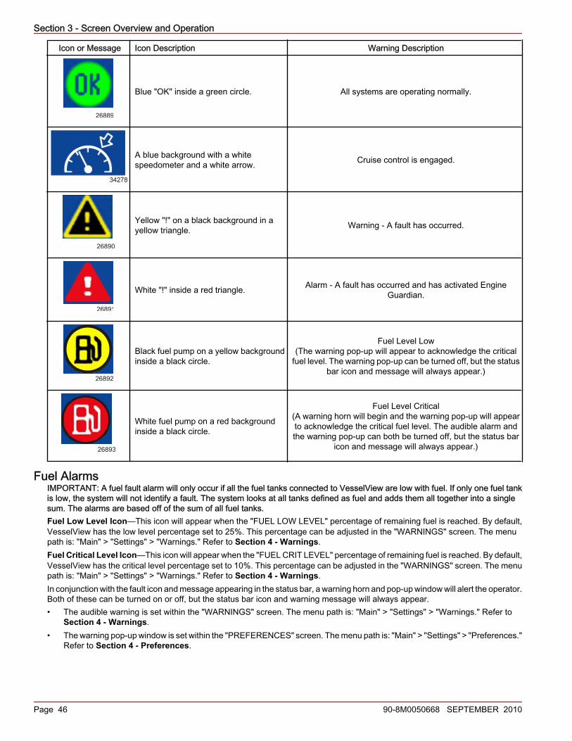
Section 3 - Screen Overview and Operation
Page 46 90-8M0050668 SEPTEMBER 2010
Icon or Message Icon Description Warning Description
26889
Blue "OK" inside a green circle. All systems are operating normally.
34278
A blue background with a whitespeedometer and a white arrow. Cruise control is engaged.
26890
Yellow "!" on a black background in ayellow triangle. Warning ‑ A fault has occurred.
26891
White "!" inside a red triangle. Alarm ‑ A fault has occurred and has activated EngineGuardian.
26892
Black fuel pump on a yellow backgroundinside a black circle.
Fuel Level Low(The warning pop‑up will appear to acknowledge the critical
fuel level. The warning pop‑up can be turned off, but the statusbar icon and message will always appear.)
26893
White fuel pump on a red backgroundinside a black circle.
Fuel Level Critical(A warning horn will begin and the warning pop‑up will appearto acknowledge the critical fuel level. The audible alarm andthe warning pop‑up can both be turned off, but the status bar
icon and message will always appear.)
Fuel AlarmsIMPORTANT: A fuel fault alarm will only occur if all the fuel tanks connected to VesselView are low with fuel. If only one fuel tankis low, the system will not identify a fault. The system looks at all tanks defined as fuel and adds them all together into a singlesum. The alarms are based off of the sum of all fuel tanks.Fuel Low Level Icon—This icon will appear when the "FUEL LOW LEVEL" percentage of remaining fuel is reached. By default,VesselView has the low level percentage set to 25%. This percentage can be adjusted in the "WARNINGS" screen. The menupath is: "Main" > "Settings" > "Warnings." Refer to Section 4 - Warnings.Fuel Critical Level Icon—This icon will appear when the "FUEL CRIT LEVEL" percentage of remaining fuel is reached. By default,VesselView has the critical level percentage set to 10%. This percentage can be adjusted in the "WARNINGS" screen. The menupath is: "Main" > "Settings" > "Warnings." Refer to Section 4 - Warnings.In conjunction with the fault icon and message appearing in the status bar, a warning horn and pop‑up window will alert the operator.Both of these can be turned on or off, but the status bar icon and warning message will always appear.• The audible warning is set within the "WARNINGS" screen. The menu path is: "Main" > "Settings" > "Warnings." Refer to
Section 4 - Warnings.• The warning pop‑up window is set within the "PREFERENCES" screen. The menu path is: "Main" > "Settings" > "Preferences."
Refer to Section 4 - Preferences.

Section 3 - Screen Overview and Operation
90-8M0050668 SEPTEMBER 2010 Page 47
Using the Menu PanelThe menu button opens the specific window information that is displayed in the propulsion, vessel, or environment and navigationscreens. The menu button is also a quick access to the calibration, settings, settings 2, alarms, system, and RPM bands informationscreens. To use the menu panel, follow these steps:1. Press the menu button. The menu panel specific to the currently open screen category ("Propulsion," "Vessel," "Env/Nav")
appears.2. Use the arrow button to navigate to the appropriate menu panel.3. Press the check button to confirm your choice.
a. To see the available propulsion screens, press the propulsion button and then the menu button. The "Propulsion" menupanel appears.IMPORTANT: The available VesselView menu items and options may display differently than those shown in thefollowing illustrations. Menu items and options are dependent on the engine type, and if screens have been manuallyturned on or off.
34370
Propulsion
Engine Status
Perf & Fuel
Peak Perf
Trim
Troll
Cruise Control
Boost
Tab
Smart Tow
Propulsion Menu Panel
b. To see the available vessel screens, press the vessel button and then the menu button. The "Vessel" menu panelappears.
Vessel
Vessel Status
Tank Status
Generator
Steer Position
34569
Vessel Menu Panel
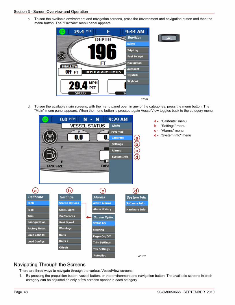
Section 3 - Screen Overview and Operation
Page 48 90-8M0050668 SEPTEMBER 2010
c. To see the available environment and navigation screens, press the environment and navigation button and then themenu button. The "Env/Nav" menu panel appears.
Env Nav
Depth
Trip Log
Navigation
Fuel To Wpt
/
37089
Autopilot
Joystick
Skyhook
d. To see the available main screens, with the menu panel open in any of the categories, press the menu button. The"Main" menu panel appears. When the menu button is pressed again VesselView toggles back to the category menu.
a - "Calibrate" menub - "Settings" menuc - "Alarms" menud - "System Info" menu
Navigating Through the ScreensThere are three ways to navigate through the various VesselView screens.1. By pressing the propulsion button, vessel button, or the environment and navigation button. The available screens in each
category can be adjusted so only a few screens appear in each category.
SettingsScreen Options
Clock/Light
Preferences
Boat Speed
Warnings
Units
Units 2
Offsets
Alarms
Alarm History
Active Alarms
System Info
Hardware Info
Software Info
45162
abcd
dcbaCalibrateTank
Tabs
Trim
Configuration
Factory Reset
Save Configs
Load Configs
Screen Optio.Status bar
Steering
Autopilot
Main
Calibrate
Settings
Alarms
System Info
Favorites
Screen Optio.Status bar
Steering
Trim Settings
Tab Settings
Autopilot
Pages On/Off

Section 3 - Screen Overview and Operation
90-8M0050668 SEPTEMBER 2010 Page 49
2. By pressing the left or right arrow button on the arrow pad. This will toggle through the available screens of the selectedcategory.
3. By pressing the menu button. The available screens in each category will appear in the menu list of data screens.
Using Pop‑Up WindowsPop‑up windows appear within screens. Pop‑up windows show alarms, allow access to controls or functions specific to a screen,and allow changes to settings or calibration.The control icon appears in the upper left corner of any screen that includes a pop‑up window for access to controls and screenfunctions. The control icon disappears about 3 seconds after each screen is loaded. To open a pop‑up window from one of thesescreens, press the check button. To close any pop‑up window, press the "X" button.
26876
Control icon
Alarms and FaultsSome alarms and faults display pop‑up windows to notify you of a condition requiring your attention. Refer to Section 4 -Alarms for more information about alarms and fault codes.To close a pop‑up window displaying an alarm or fault information, press the "X" button. You can review the alarm information intwo ways:1. Press the brightness/alarm button to see active alarms and faults in a pop‑up window.2. Review the alarm information in the "Main" menu.
a. Press the menu button until the "Main" menu appears.b. Use the down arrow button to select "Alarms."c. Press the check button to open the "Alarms" menu.d. Use the down arrow button to select "Active Alarms" to review current alarm information, or select "Alarm History" to
review all alarms recorded since the last factory reset.e. Press the check button to open the alarm screen you chose.f. Press the "X" button to close the pop‑up window when you finish reviewing the alarms.
Screen Brightness
26950
Screen brightness pop-up window
The brightness pop‑up window controls the brightness of the screen on a scale of 0 to 15. To adjust screen brightness, use thefollowing steps:1. Press the brightness/alarm button. The "Screen Brightness" pop‑up window appears.2. Use the right or left arrow button to adjust screen brightness. The right arrow increases brightness. The left arrow decreases
brightness.3. Press the check button to save the selected screen brightness.

Section 3 - Screen Overview and Operation
Notes:
Page 50 90-8M0050668 SEPTEMBER 2010

Section 4 - Main Menu
90-8M0050668 SEPTEMBER 2010 Page 51
Section 4 - Main MenuTable of ContentsFavorites............................................................................... 52Calibrate Menu..................................................................... 52
Tank Menu .................................................................... 52Tabs Menu .................................................................... 52Trim Menu .................................................................... 52Configuration Menu ...................................................... 52Factory Reset Menu ..................................................... 52Save Configs Menu ...................................................... 53Load Configs Menu ...................................................... 53
Settings................................................................................. 53Settings Menu Options..................................................53Status Bar Options.........................................................54Steering Options............................................................54Pages On/Off Options....................................................55
Page/Screen Favorites .......................................... 56Trim Setting...................................................................56Tab Settings...................................................................57Autopilot Config.............................................................57Clock/Light.....................................................................58Preferences...................................................................59
Boat Speed....................................................................60Warnings........................................................................61Units...............................................................................61Units 2............................................................................62Offsets...........................................................................63
Alarms.................................................................................. 64Alarms Menu Options....................................................64VesselView Warning Horn Strategy...............................64Active Alarms.................................................................65
Fault Icons ............................................................. 66Viewing Active Alarms ........................................... 67Viewing Alarm Details ........................................... 68
Alarm History.................................................................68Alarm History Details ............................................. 68Clearing Alarm History .......................................... 69
System Information............................................................... 70System Information Menu Options................................70Software Information......................................................70Hardware Information....................................................71
4

Section 4 - Main Menu
Page 52 90-8M0050668 SEPTEMBER 2010
Favorites"Favorites" is a function of VesselView that allows the viewer to select specific screens as their favorite type of information thatwill scroll through the various pages. The length of time the favorite information screen remains visible is programmable from 5to 20 seconds. Each category; "Propulsion," "Vessel," or "Environment and Navigation," has a variety of default screen layoutswith different information on each. Each screen option selected will have a heart shaped icon indicating the selection is designatedas a favorite. Favorites will not populate the category until the pages are selected as a favorite. The favorites can be selected inthe "PAGES ON/OFF" screen. The menu path is: "Main" > "Settings" > "Screen Options." The favorites duration time can bechanged in the "PREFERENCES" screen. The menu path is: "Main" > "Settings" > "Preferences."
MainCalibrate
Settings
Alarms
System Info
Main
Calibrate
Settings
Alarms
System Info
Favorites Favorites
Cruise Control
Trim
Boost
Vessel Status
Fuel To Wpt
34576
Calibrate MenuThe "Calibrate" menu enables access to configure and adjust parameters within the VesselView for multiple types of holding tanks,tabs, trim, helm location, VesselView location, number of engines, organize screen displays, factory reset the settings, sensordetection, save (export) the VesselView configurations to a USB memory stick, and to load (import) saved VesselViewconfigurations from a USB memory stick.
Tank MenuThe "Tank" calibration menu option provides flexibility to make adjustments to existing calibration settings or to perform thecalibration process without the assistance of the setup wizard. These tanks can be configured specifically for their size, shape,and what they contain; fuel, oil, water, or waste. The process begins with defining the purpose of each tank on the vessel. Thenext screen asks for the size of each tank. The third screen asks for a location label for each tank. This label is an identifier onthe VesselView screen where the tank physically resides on the vessel.
Tabs MenuThe "Tabs" calibration procedure utilizes the same tab calibration screens used in the setup wizard. There are additional calibrationoptions that provide flexibility to make adjustments for the tab position sensor resistance changes as the tab is raised or lowered.These adjustments may be necessary for the VesselView tab screen to accurately represent the positions of the tab.
Trim MenuThe "Trim" calibration menu provides options not available with the setup wizard. There are two methods of calibrating the trim."DEFAULT" is a quick method and may not display the position accurately. The "MANUAL" method provides flexibility to makeadjustments for the trim position sensor resistance changes as the trim is raised or lowered. These adjustments may be necessaryfor the VesselView trim screen to accurately represent the positions of the trim.
Configuration MenuThe "Configuration" calibration menu provides options to assign the VesselView a helm location and a unique device identificationnumber when more than one VesselView is used. It is also used to define the number of engines and select where the enginedata should be displayed on the VesselView screen.
Factory Reset MenuThe "Factory Reset" menu is used to reset all VesselView settings to the factory default, or to perform a sensor detection. Whenthe VesselView is first configured during the setup wizard, the system will automatically detect sensors that are present and ignoressensor inputs that have no sensors attached. If a sensor is removed from the system after the initial configuration, VesselViewwill show faults for the removed sensor. VesselView will scan for sensors and eliminate the fault message.
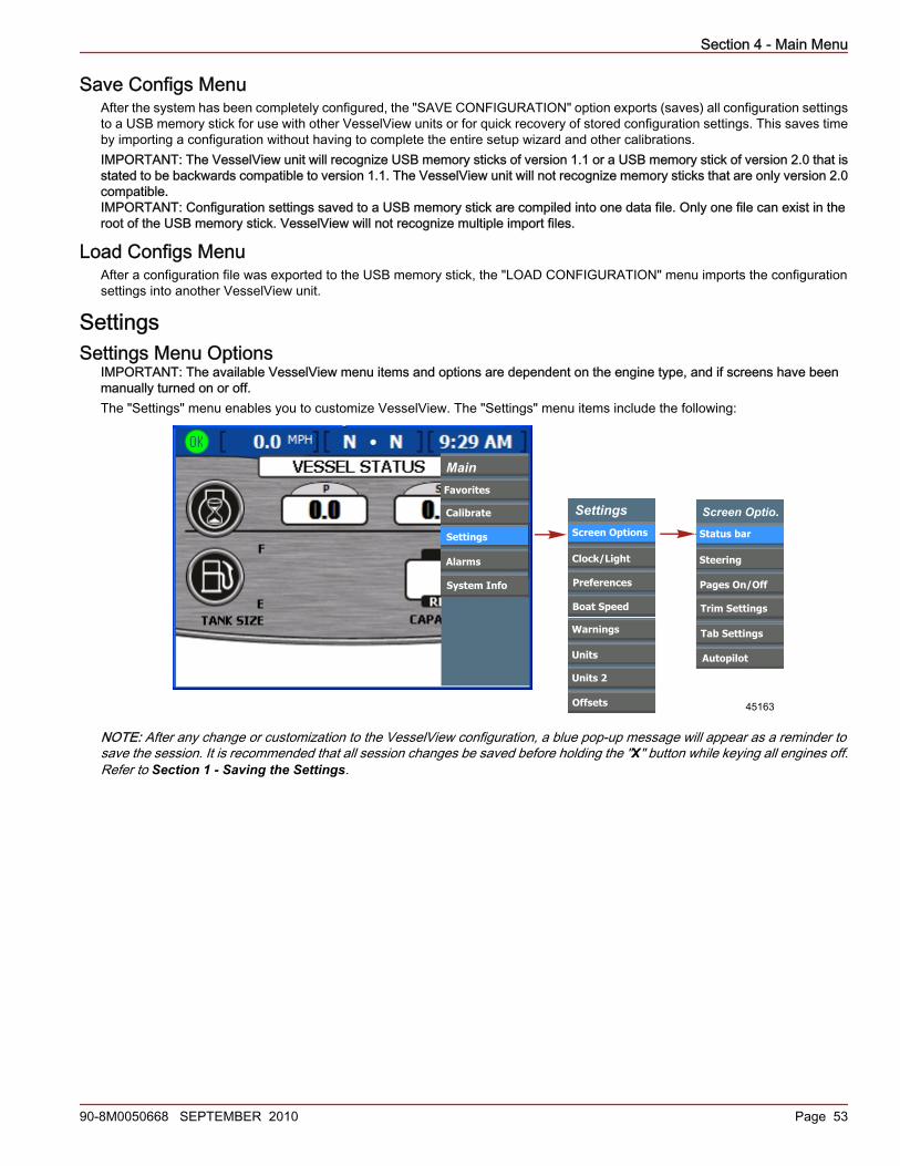
Section 4 - Main Menu
90-8M0050668 SEPTEMBER 2010 Page 53
Save Configs MenuAfter the system has been completely configured, the "SAVE CONFIGURATION" option exports (saves) all configuration settingsto a USB memory stick for use with other VesselView units or for quick recovery of stored configuration settings. This saves timeby importing a configuration without having to complete the entire setup wizard and other calibrations.IMPORTANT: The VesselView unit will recognize USB memory sticks of version 1.1 or a USB memory stick of version 2.0 that isstated to be backwards compatible to version 1.1. The VesselView unit will not recognize memory sticks that are only version 2.0compatible.IMPORTANT: Configuration settings saved to a USB memory stick are compiled into one data file. Only one file can exist in theroot of the USB memory stick. VesselView will not recognize multiple import files.
Load Configs MenuAfter a configuration file was exported to the USB memory stick, the "LOAD CONFIGURATION" menu imports the configurationsettings into another VesselView unit.
SettingsSettings Menu Options
IMPORTANT: The available VesselView menu items and options are dependent on the engine type, and if screens have beenmanually turned on or off.The "Settings" menu enables you to customize VesselView. The "Settings" menu items include the following:
MainCalibrate
Settings
Alarms
System Info
SettingsScreen Options
Clock/Light
Preferences
Boat Speed
Warnings
Units
Units 2
Offsets 45163
Screen Optio.Status bar
Steering
Trim Settings
Tab Settings
Autopilot
Main
Calibrate
Settings
Alarms
System Info
Favorites
Screen Optio.Status bar
Steering
Autopilot
Screen Optio.Status bar
Steering
Trim Settings
Tab Settings
Autopilot
Pages On/Off
NOTE: After any change or customization to the VesselView configuration, a blue pop‑up message will appear as a reminder tosave the session. It is recommended that all session changes be saved before holding the "X" button while keying all engines off.Refer to Section 1 - Saving the Settings.

Section 4 - Main Menu
Page 54 90-8M0050668 SEPTEMBER 2010
Status Bar OptionsThe status bar is located at the top of the screen and is separated in three different data options. Changes to the status bar aremade in the "STATUS BAR" screen. The menu path is: "Main" > "Settings" > "Screen Options" > "Status bar." Press the checkbutton to open the "STATUS BAR" screen.
a - Left datab - Center datac - Right data
1. The "STATUS BAR" screen will open with the "LEFT DATA" option highlighted in blue.2. Press the left or right arrow on the arrow pad to scroll through the available display data. The data available to display is:
• "TIME"—Clock• "SPEED"—Vessel speed (default)• "SPD OVR GRD"—Speed over ground (GPS)• "SEA TEMP"—Seawater temperature• "GEAR"—Shift position• "FUEL USAGE"—Fuel used• "FUEL LEVEL"—Fuel tank level• "DEPTH"—Water depth• "CRS OVR GND"—Course over ground (GPS)
• "BRNG TO WP"—Bearing to waypoint (GPS)• "AIR TEMP"—Air temperature• "STBD TAB"—Starboard tab position• "PORT TAB"—Port tab position• "STBD TRIM"—Starboard trim position• "PORT TRIM"—Port trim position• "SC TRIM"—Starboard center trim position• "PC TRIM"—Port center trim position• "VOLTS"—Battery voltage
3. Press the down arrow on the arrow pad to proceed to the "CENTER DATA" option.4. Press the left or right arrow on the arrow pad to scroll through the available display data.5. Press the down arrow on the arrow pad to proceed to the "RIGHT DATA" option.6. Press the left or right arrow on the arrow pad to scroll through the available display data.7. Once you have selected the status bar display data, press the check button to save the session.NOTE: After any change or customization to the VesselView configuration, a blue pop‑up message will appear as a reminder tosave the session. It is recommended that all session changes be saved before holding the "X" button while keying all engines off.Refer to Section 1 - Saving the Settings.
Steering OptionsThe "STEERING" screen enables you to set the display data in the vessel screen "STEERING POSITION." Refer to Section 6 -Vessel Menu. The menu path is: "Main" > "Settings" > "Screen Options" > "Steering." Press the check button to open the"STEERING" screen.1. Use the left or right arrow to scroll through the options in the "LEFT DATA AREA" option. Choose which information to display
in the option appearing on the bottom left of the "STEERING POSITION" screen. The available options are:• "BOAT SPEED"—Vessel speed• "WIND DIR"—Wind direction• "WATER DEPTH"—Water depth• "GEAR POS"—Gear position• "WIND SPEED"—Wind speed
a b c
a
b
c
27132
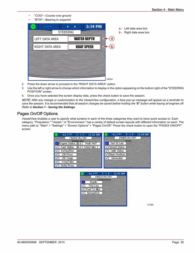
Section 4 - Main Menu
90-8M0050668 SEPTEMBER 2010 Page 55
• "COG"—Course over ground• "BTW"—Bearing to waypoint
a - Left data area boxb - Right data area box
2. Press the down arrow to proceed to the "RIGHT DATA AREA" option.3. Use the left or right arrow to choose which information to display in the option appearing on the bottom right of the "STEERING
POSITION" screen.4. Once you have selected the screen display data, press the check button to save the session.NOTE: After any change or customization to the VesselView configuration, a blue pop‑up message will appear as a reminder tosave the session. It is recommended that all session changes be saved before holding the "X" button while keying all engines off.Refer to Section 1 - Saving the Settings.
Pages On/Off OptionsVesselView enables a user to specify what screens in each of the three categories they want to have quick access to. Eachcategory; "Propulsion," "Vessel," or "Environment," has a variety of default screen layouts with different information on each. Themenu path is: "Main" > "Settings" > "Screen Options" > "Pages On/Off." Press the check button to open the "PAGES ON/OFF"screen.
37088
STEERING
LEFT DATA AREA
RIGHT DATA AREA
STEERING OFFSET 0
WATER DEPTH
BOAT SPEEDO
a
b
34554
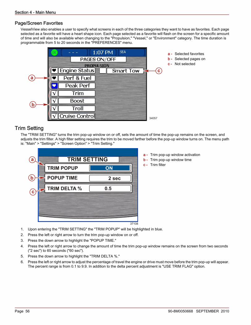
Section 4 - Main Menu
Page 56 90-8M0050668 SEPTEMBER 2010
Page/Screen FavoritesVesselView also enables a user to specify what screens in each of the three categories they want to have as favorites. Each pageselected as a favorite will have a heart shape icon. Each page selected as a favorite will flash on the screen for a specific amountof time and will also be available when changing to the "Propulsion," "Vessel," or "Environment" category. The time duration isprogrammable from 5 to 20 seconds in the "PREFERENCES" menu.
a - Selected favoritesb - Selected pages onc - Not selected
Trim SettingThe "TRIM SETTING" turns the trim pop‑up window on or off, sets the amount of time the pop‑up remains on the screen, andadjusts the trim filter. A high filter setting requires the trim to be moved farther before the pop‑up window turns on. The menu pathis: "Main" > "Settings" > "Screen Option" > "Trim Setting."
a - Trim pop‑up window activationb - Trim pop‑up window timec - Trim filter
1. Upon entering the "TRIM SETTING" the "TRIM POPUP" will be highlighted in blue.2. Press the left or right arrow to turn the trim pop‑up window on or off.3. Press the down arrow to highlight the "POPUP TIME."4. Press the left or right arrow to change the amount of time the trim pop‑up window remains on the screen from two seconds
("2 sec") to 60 seconds ("60 sec").5. Press the down arrow to highlight the "TRIM DELTA %."6. Press the left or right arrow to adjust the percentage of travel the engine or drive must move before the trim pop‑up will appear.
The percent range is from 0.1 to 9.9. In addition to the delta percent adjustment is "USE TRIM FLAG" option.
a
b
c
34057
37108
TRIM SETTINGTRIM POPUP
POPUP TIME
TRIM DELTA %
ON
2 sec
0.5
a
b
c
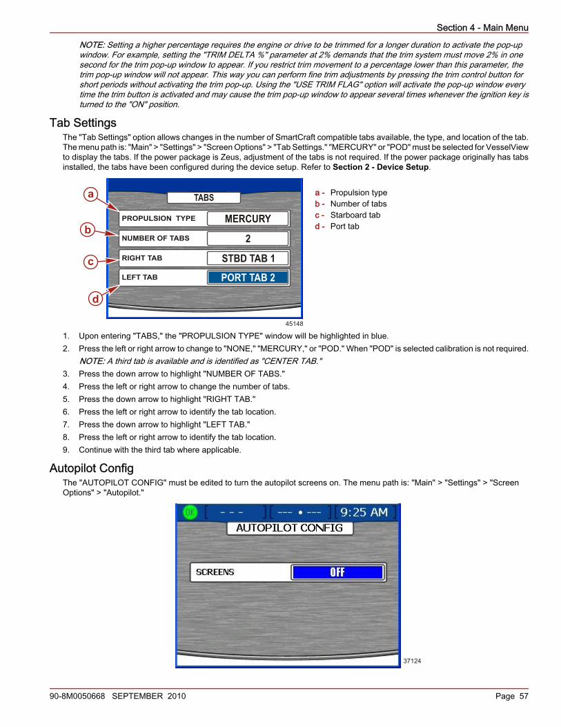
Section 4 - Main Menu
90-8M0050668 SEPTEMBER 2010 Page 57
NOTE: Setting a higher percentage requires the engine or drive to be trimmed for a longer duration to activate the pop‑upwindow. For example, setting the "TRIM DELTA %" parameter at 2% demands that the trim system must move 2% in onesecond for the trim pop‑up window to appear. If you restrict trim movement to a percentage lower than this parameter, thetrim pop‑up window will not appear. This way you can perform fine trim adjustments by pressing the trim control button forshort periods without activating the trim pop‑up. Using the "USE TRIM FLAG" option will activate the pop‑up window everytime the trim button is activated and may cause the trim pop‑up window to appear several times whenever the ignition key isturned to the "ON" position.
Tab SettingsThe "Tab Settings" option allows changes in the number of SmartCraft compatible tabs available, the type, and location of the tab.The menu path is: "Main" > "Settings" > "Screen Options" > "Tab Settings." "MERCURY" or "POD" must be selected for VesselViewto display the tabs. If the power package is Zeus, adjustment of the tabs is not required. If the power package originally has tabsinstalled, the tabs have been configured during the device setup. Refer to Section 2 - Device Setup.
a - Propulsion typeb - Number of tabsc - Starboard tabd - Port tab
1. Upon entering "TABS," the "PROPULSION TYPE" window will be highlighted in blue.2. Press the left or right arrow to change to "NONE," "MERCURY," or "POD." When "POD" is selected calibration is not required.
NOTE: A third tab is available and is identified as "CENTER TAB."3. Press the down arrow to highlight "NUMBER OF TABS."4. Press the left or right arrow to change the number of tabs.5. Press the down arrow to highlight "RIGHT TAB."6. Press the left or right arrow to identify the tab location.7. Press the down arrow to highlight "LEFT TAB."8. Press the left or right arrow to identify the tab location.9. Continue with the third tab where applicable.
Autopilot ConfigThe "AUTOPILOT CONFIG" must be edited to turn the autopilot screens on. The menu path is: "Main" > "Settings" > "ScreenOptions" > "Autopilot."
37124
PROPULSION TYPE MERCURY
45148
TABS
NUMBER OF TABS 2RIGHT TAB STBD TAB 1LEFT TAB PORT TAB 2
a
b
c
d

Section 4 - Main Menu
Page 58 90-8M0050668 SEPTEMBER 2010
1. Upon entering "AUTOPILOT CONFIG," the "SCREENS" option will be highlighted in blue.2. Use the left arrow to turn the autopilot screens "OFF."3. Use the right arrow to turn the autopilot screens "ON."
Clock/LightThe settings for the clock are found in the "CLOCK/BRIGHTNESS" screen. The menu path is: "Main" > "Settings" > "Clock/Light."Press the check button to open the "CLOCK/BRIGHTNESS" screen.
a - Hoursb - Minutesc - 12/24 hour displayd - Brightness
1. Upon entering the "CLOCK/BRIGHTNESS" screen, the "HOURS (0‑23)" option will be highlighted in blue.2. Press the left or right arrow on the arrow pad to select the hour of the day based on a 24 hour clock, even if you use a 12
hour clock display.3. Press the down arrow on the arrow pad to proceed to the "MINUTES" option.4. Press the left or right arrow on the arrow pad to select minutes after the hour.5. Press the down arrow on the arrow pad to proceed to the "12/24 HR DISPLAY" option.6. Press the left or right arrow on the arrow pad to choose between the 12 and 24 hour clock display.7. Press the down arrow on the arrow pad to proceed to the "BRIGHTNESS" option.8. Press the left or right arrow on the arrow pad to adjust screen brightness. The right arrow increases brightness and the left
arrow decreases brightness.9. Once you have selected the preferred clock settings, press the check button to save the session.NOTE: After any change or customization to the VesselView configuration, a blue pop‑up message will appear as a reminder tosave the session. It is recommended that all session changes be saved before holding the "X" button while keying all engines off.Refer to Section 1 - Saving the Settings.
a
b
c
d
27135
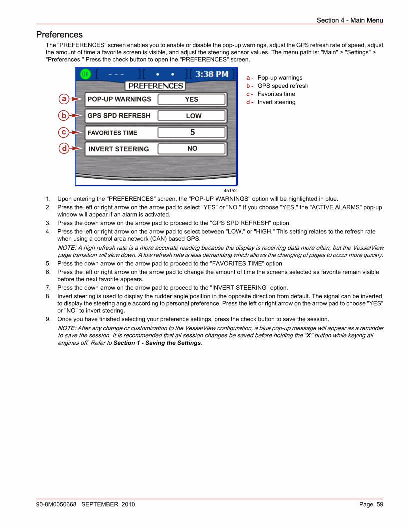
Section 4 - Main Menu
90-8M0050668 SEPTEMBER 2010 Page 59
PreferencesThe "PREFERENCES" screen enables you to enable or disable the pop‑up warnings, adjust the GPS refresh rate of speed, adjustthe amount of time a favorite screen is visible, and adjust the steering sensor values. The menu path is: "Main" > "Settings" >"Preferences." Press the check button to open the "PREFERENCES" screen.
a - Pop‑up warningsb - GPS speed refreshc - Favorites timed - Invert steering
1. Upon entering the "PREFERENCES" screen, the "POP‑UP WARNINGS" option will be highlighted in blue.2. Press the left or right arrow on the arrow pad to select "YES" or "NO." If you choose "YES," the "ACTIVE ALARMS" pop‑up
window will appear if an alarm is activated.3. Press the down arrow on the arrow pad to proceed to the "GPS SPD REFRESH" option.4. Press the left or right arrow on the arrow pad to select between "LOW," or "HIGH." This setting relates to the refresh rate
when using a control area network (CAN) based GPS.NOTE: A high refresh rate is a more accurate reading because the display is receiving data more often, but the VesselViewpage transition will slow down. A low refresh rate is less demanding which allows the changing of pages to occur more quickly.
5. Press the down arrow on the arrow pad to proceed to the "FAVORITES TIME" option.6. Press the left or right arrow on the arrow pad to change the amount of time the screens selected as favorite remain visible
before the next favorite appears.7. Press the down arrow on the arrow pad to proceed to the "INVERT STEERING" option.8. Invert steering is used to display the rudder angle position in the opposite direction from default. The signal can be inverted
to display the steering angle according to personal preference. Press the left or right arrow on the arrow pad to choose "YES"or "NO" to invert steering.
9. Once you have finished selecting your preference settings, press the check button to save the session.NOTE: After any change or customization to the VesselView configuration, a blue pop‑up message will appear as a reminderto save the session. It is recommended that all session changes be saved before holding the "X" button while keying allengines off. Refer to Section 1 - Saving the Settings.
a
b
c
d
45152
INVERT STEERING NO
POP-UP WARNINGS YES
GPS SPD REFRESH LOW
FAVORITES TIME 5
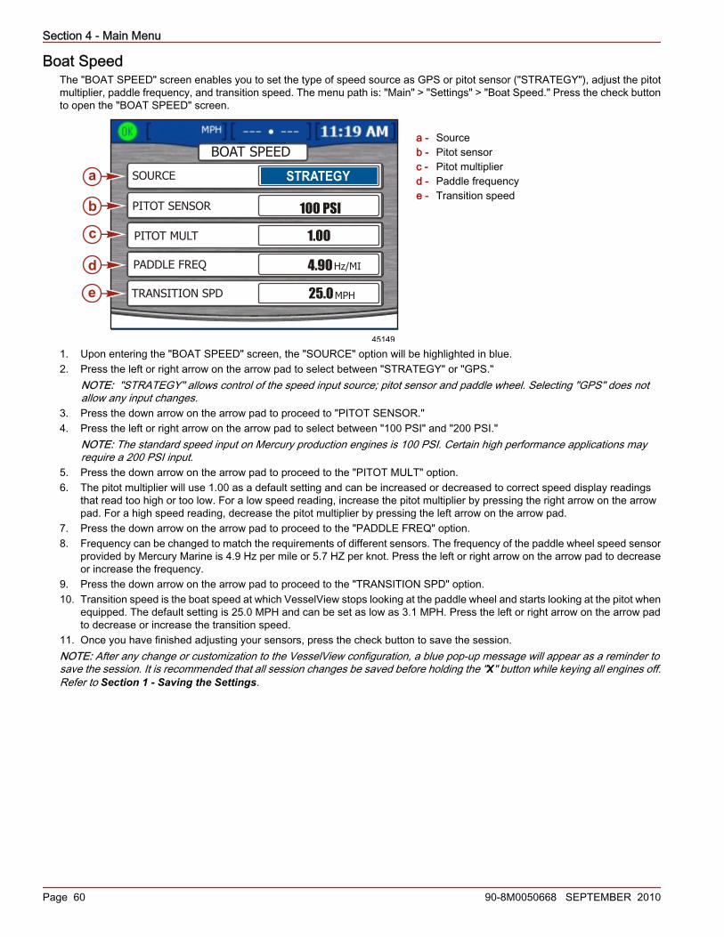
Section 4 - Main Menu
Page 60 90-8M0050668 SEPTEMBER 2010
Boat SpeedThe "BOAT SPEED" screen enables you to set the type of speed source as GPS or pitot sensor ("STRATEGY"), adjust the pitotmultiplier, paddle frequency, and transition speed. The menu path is: "Main" > "Settings" > "Boat Speed." Press the check buttonto open the "BOAT SPEED" screen.
a - Sourceb - Pitot sensorc - Pitot multiplierd - Paddle frequencye - Transition speed
1. Upon entering the "BOAT SPEED" screen, the "SOURCE" option will be highlighted in blue.2. Press the left or right arrow on the arrow pad to select between "STRATEGY" or "GPS."
NOTE: "STRATEGY" allows control of the speed input source; pitot sensor and paddle wheel. Selecting "GPS" does notallow any input changes.
3. Press the down arrow on the arrow pad to proceed to "PITOT SENSOR."4. Press the left or right arrow on the arrow pad to select between "100 PSI" and "200 PSI."
NOTE: The standard speed input on Mercury production engines is 100 PSI. Certain high performance applications mayrequire a 200 PSI input.
5. Press the down arrow on the arrow pad to proceed to the "PITOT MULT" option.6. The pitot multiplier will use 1.00 as a default setting and can be increased or decreased to correct speed display readings
that read too high or too low. For a low speed reading, increase the pitot multiplier by pressing the right arrow on the arrowpad. For a high speed reading, decrease the pitot multiplier by pressing the left arrow on the arrow pad.
7. Press the down arrow on the arrow pad to proceed to the "PADDLE FREQ" option.8. Frequency can be changed to match the requirements of different sensors. The frequency of the paddle wheel speed sensor
provided by Mercury Marine is 4.9 Hz per mile or 5.7 HZ per knot. Press the left or right arrow on the arrow pad to decreaseor increase the frequency.
9. Press the down arrow on the arrow pad to proceed to the "TRANSITION SPD" option.10. Transition speed is the boat speed at which VesselView stops looking at the paddle wheel and starts looking at the pitot when
equipped. The default setting is 25.0 MPH and can be set as low as 3.1 MPH. Press the left or right arrow on the arrow padto decrease or increase the transition speed.
11. Once you have finished adjusting your sensors, press the check button to save the session.NOTE: After any change or customization to the VesselView configuration, a blue pop‑up message will appear as a reminder tosave the session. It is recommended that all session changes be saved before holding the "X" button while keying all engines off.Refer to Section 1 - Saving the Settings.
BOAT SPEED
a
b
c
d
e
45149
SOURCE
PITOT SENSOR
PITOT MULT
PADDLE FREQ
TRANSITION SPD
STRATEGY
100 PSI
1.00
4.90Hz/MI
25.0MPH

Section 4 - Main Menu
90-8M0050668 SEPTEMBER 2010 Page 61
WarningsThe "WARNINGS" screen enables you to turn the VesselView warning horn on or off and to adjust the fuel level alarm values.The menu path is: "Main" > "Settings" > "Warnings." Press the check button to open the "WARNINGS" screen.
a - Warning hornb - Fuel critical levelc - Fuel low level
1. Upon entering the "WARNINGS" screen, the "WARNING HORN" option will be highlighted in blue.NOTE: The VesselView warning horn can be turned "ON" or "OFF." By selecting "OFF," all engine alarms will be heard throughthe key switch harness warning horn. By selecting "ON," all alarms will be heard through the key switch harness horn andthe VesselView horn. For warning horn details, refer to Alarms.
2. Press the left or right arrow on the arrow pad to select either "ON" or "OFF."3. Press the down arrow on the arrow pad to proceed to the "FUEL CRIT LEVEL" option.4. The fuel critical level default setting is 10% and can be increased by pressing the right arrow on the arrow pad.
NOTE: The fuel critical level percentage cannot be set below 10%, or higher than the fuel low level percentage.5. Press the down arrow on the arrow pad to proceed to the "FUEL LOW LEVEL" option.6. The fuel low level default setting is 25% and can be increased by pressing the right arrow on the arrow pad. The highest you
may set the fuel low level is 50%.NOTE: The fuel low level percentage cannot be set below the fuel critical level percentage.
7. Once you have finished adjusting your warnings, press the check button to save the session.NOTE: After any change or customization to the VesselView configuration, a blue pop‑up message will appear as a reminder tosave the session. It is recommended that all session changes be saved before holding the "X" button while keying all engines off.Refer to Section 1 - Saving the Settings.
UnitsThe "UNITS" screen enables you to set the units of measure for speed, depth, distance, temperature, and pressure. The menupath is: "Main" > "Settings" > "Units." Press the check button to open the "UNITS" screen.
a - Speedb - Depthc - Distanced - Temperaturee - Pressure
a
b
c
27143
a
b
c
d
e
27317
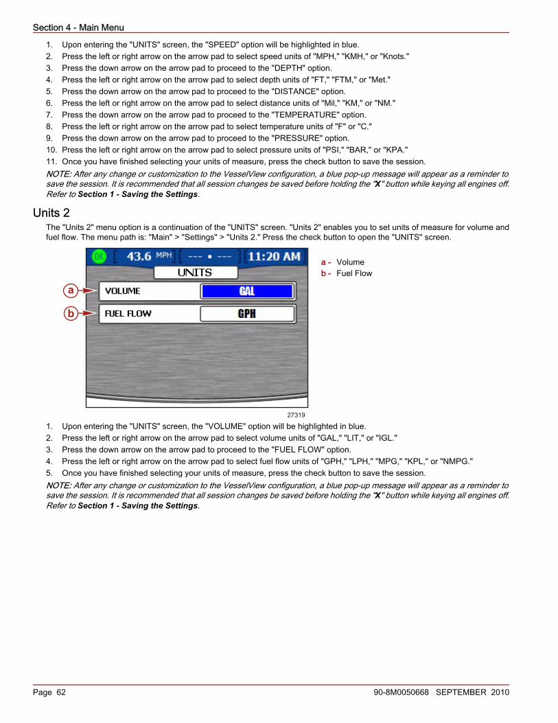
Section 4 - Main Menu
Page 62 90-8M0050668 SEPTEMBER 2010
1. Upon entering the "UNITS" screen, the "SPEED" option will be highlighted in blue.2. Press the left or right arrow on the arrow pad to select speed units of "MPH," "KMH," or "Knots."3. Press the down arrow on the arrow pad to proceed to the "DEPTH" option.4. Press the left or right arrow on the arrow pad to select depth units of "FT," "FTM," or "Met."5. Press the down arrow on the arrow pad to proceed to the "DISTANCE" option.6. Press the left or right arrow on the arrow pad to select distance units of "Mil," "KM," or "NM."7. Press the down arrow on the arrow pad to proceed to the "TEMPERATURE" option.8. Press the left or right arrow on the arrow pad to select temperature units of "F" or "C."9. Press the down arrow on the arrow pad to proceed to the "PRESSURE" option.10. Press the left or right arrow on the arrow pad to select pressure units of "PSI," "BAR," or "KPA."11. Once you have finished selecting your units of measure, press the check button to save the session.NOTE: After any change or customization to the VesselView configuration, a blue pop‑up message will appear as a reminder tosave the session. It is recommended that all session changes be saved before holding the "X" button while keying all engines off.Refer to Section 1 - Saving the Settings.
Units 2The "Units 2" menu option is a continuation of the "UNITS" screen. "Units 2" enables you to set units of measure for volume andfuel flow. The menu path is: "Main" > "Settings" > "Units 2." Press the check button to open the "UNITS" screen.
a - Volumeb - Fuel Flow
1. Upon entering the "UNITS" screen, the "VOLUME" option will be highlighted in blue.2. Press the left or right arrow on the arrow pad to select volume units of "GAL," "LIT," or "IGL."3. Press the down arrow on the arrow pad to proceed to the "FUEL FLOW" option.4. Press the left or right arrow on the arrow pad to select fuel flow units of "GPH," "LPH," "MPG," "KPL," or "NMPG."5. Once you have finished selecting your units of measure, press the check button to save the session.NOTE: After any change or customization to the VesselView configuration, a blue pop‑up message will appear as a reminder tosave the session. It is recommended that all session changes be saved before holding the "X" button while keying all engines off.Refer to Section 1 - Saving the Settings.
a
b
27319

Section 4 - Main Menu
90-8M0050668 SEPTEMBER 2010 Page 63
OffsetsThe "OFFSETS" screen enables you to change the offsets in order to compensate for inaccuracies in depth, fuel, sea temperatureand steering position. The menu path is: "Main" > "Settings" > "Offsets." Press the check button to open the "OFFSETS" screen.
a - Depth offsetb - Fuel offsetc - Sea temp offsetd - Steering offset
1. Upon entering the "OFFSETS" screen, the "DEPTH OFFSET" option will be highlighted in blue.2. The depth offset default setting is 0.0 ft. Press the left or right arrow on the arrow pad to add or subtract depth offset. To set
an offset below the transducer, subtract from the depth offset. To set an offset above the transducer, add to the depth offset.
a - Depth transducerb - To set an offset below the
transducer, subtract from the depthoffset
c - No offset. Distance from depthtransducer to bottom.
d - To set an offset above thetransducer, add to the depth offset
3. Press the down arrow on the arrow pad to proceed to the "FUEL OFFSET" option.4. The fuel offset default setting is 0.00%. Press the left or right arrow on the arrow pad to add or subtract fuel offset. If the fuel
tank does not read "0" when empty, add fuel offset until it equals the incorrect amount shown remaining in the tank. Thisshould change the fuel level screen so it reads "0."NOTE: The fuel offset can only be a positive offset.
5. Press the down arrow on the arrow pad to proceed to the "SEA TEMP OFFSET" option.6. The sea temperature default setting is 0 degrees. Take the actual seawater temperature and subtract the displayed sea
temperature. Then add or subtract the difference in temperature in the "SEA TEMP OFFSET" option using the left or rightarrow on the arrow pad.
7. Press the down arrow on the arrow pad to proceed to the "STEERING OFFSET" option.8. Use the left or right arrow button to adjust the steering position in either direction.9. After making changes to the offsets, press the check button to save the session.NOTE: After any change or customization to the VesselView configuration, a blue pop‑up message will appear as a reminder tosave the session. It is recommended that all session changes be saved before holding the "X" button while keying all engines off.Refer to Section 1 - Saving the Settings.
45165
STEERING OFFSET 0O
a
b
c
d
FUEL OFFSET 0.00 %
32883
bc
d
a
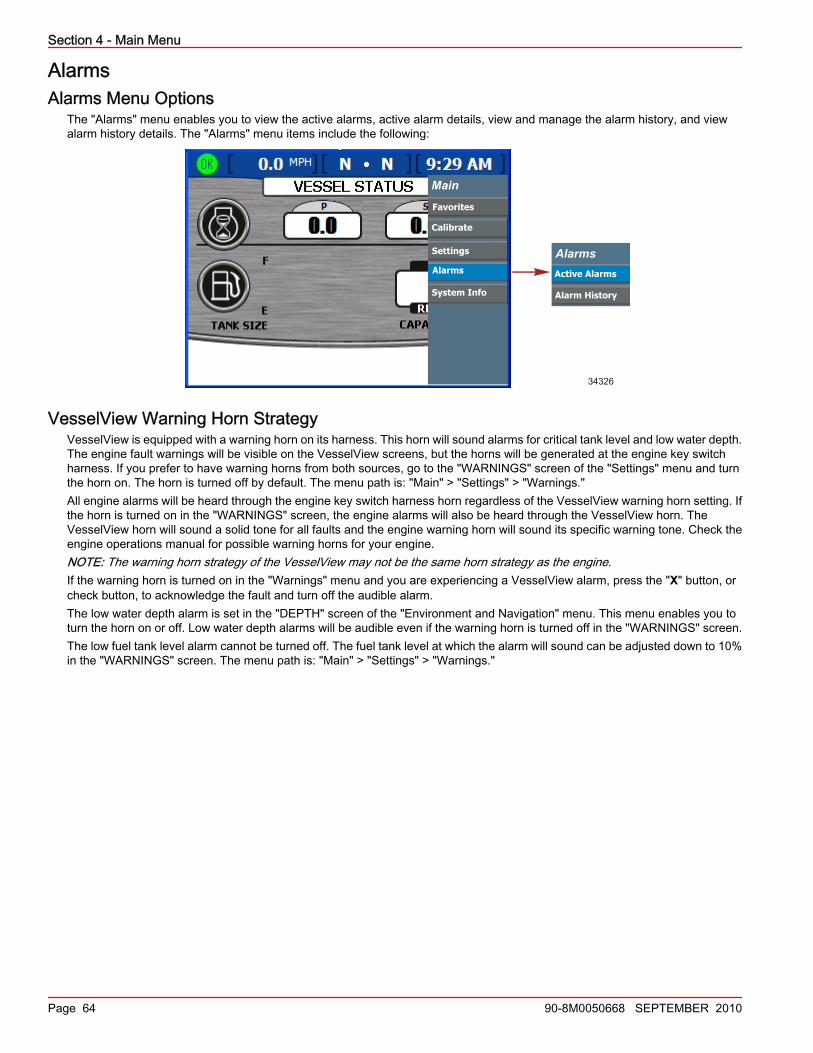
Section 4 - Main Menu
Page 64 90-8M0050668 SEPTEMBER 2010
AlarmsAlarms Menu Options
The "Alarms" menu enables you to view the active alarms, active alarm details, view and manage the alarm history, and viewalarm history details. The "Alarms" menu items include the following:
Alarms
Alarm History
Active Alarms
Main
Favorites
Calibrate
Settings
Alarms
System Info
34326
VesselView Warning Horn StrategyVesselView is equipped with a warning horn on its harness. This horn will sound alarms for critical tank level and low water depth.The engine fault warnings will be visible on the VesselView screens, but the horns will be generated at the engine key switchharness. If you prefer to have warning horns from both sources, go to the "WARNINGS" screen of the "Settings" menu and turnthe horn on. The horn is turned off by default. The menu path is: "Main" > "Settings" > "Warnings."All engine alarms will be heard through the engine key switch harness horn regardless of the VesselView warning horn setting. Ifthe horn is turned on in the "WARNINGS" screen, the engine alarms will also be heard through the VesselView horn. TheVesselView horn will sound a solid tone for all faults and the engine warning horn will sound its specific warning tone. Check theengine operations manual for possible warning horns for your engine.NOTE: The warning horn strategy of the VesselView may not be the same horn strategy as the engine.If the warning horn is turned on in the "Warnings" menu and you are experiencing a VesselView alarm, press the "X" button, orcheck button, to acknowledge the fault and turn off the audible alarm.The low water depth alarm is set in the "DEPTH" screen of the "Environment and Navigation" menu. This menu enables you toturn the horn on or off. Low water depth alarms will be audible even if the warning horn is turned off in the "WARNINGS" screen.The low fuel tank level alarm cannot be turned off. The fuel tank level at which the alarm will sound can be adjusted down to 10%in the "WARNINGS" screen. The menu path is: "Main" > "Settings" > "Warnings."

Section 4 - Main Menu
90-8M0050668 SEPTEMBER 2010 Page 65
Active AlarmsThe fault or warning will appear in the status bar. VesselView alerts the operator of any faults or warnings with an icon on the leftside of the status bar. A description of the fault or warning will appear over the other status bar options. If all systems are operatingnormally, a green icon with the word "OK" inside will be displayed.
a - Fault status icona
27171
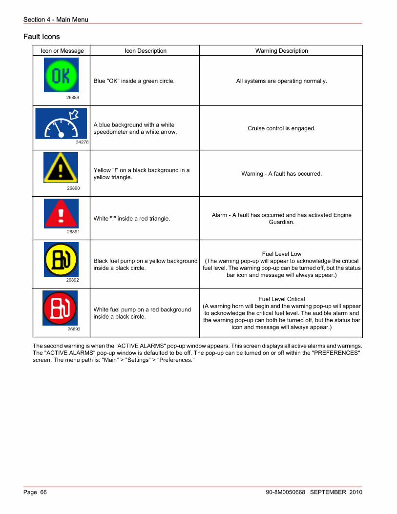
Section 4 - Main Menu
Page 66 90-8M0050668 SEPTEMBER 2010
Fault Icons
Icon or Message Icon Description Warning Description
26889
Blue "OK" inside a green circle. All systems are operating normally.
34278
A blue background with a whitespeedometer and a white arrow. Cruise control is engaged.
26890
Yellow "!" on a black background in ayellow triangle. Warning ‑ A fault has occurred.
26891
White "!" inside a red triangle. Alarm ‑ A fault has occurred and has activated EngineGuardian.
26892
Black fuel pump on a yellow backgroundinside a black circle.
Fuel Level Low(The warning pop‑up will appear to acknowledge the critical
fuel level. The warning pop‑up can be turned off, but the statusbar icon and message will always appear.)
26893
White fuel pump on a red backgroundinside a black circle.
Fuel Level Critical(A warning horn will begin and the warning pop‑up will appearto acknowledge the critical fuel level. The audible alarm andthe warning pop‑up can both be turned off, but the status bar
icon and message will always appear.)
The second warning is when the "ACTIVE ALARMS" pop‑up window appears. This screen displays all active alarms and warnings.The "ACTIVE ALARMS" pop‑up window is defaulted to be off. The pop‑up can be turned on or off within the "PREFERENCES"screen. The menu path is: "Main" > "Settings" > "Preferences."

Section 4 - Main Menu
90-8M0050668 SEPTEMBER 2010 Page 67
If more than one fault has occurred, the faults will appear in the sequence they occurred.
a - Engine identificationb - Arrow cursorc - Fault short textd - Fault icon
Viewing Active AlarmsYou can review active alarm information in two ways:1. By pressing the brightness/alarm button to see the "ACTIVE ALARMS" screen. The "ACTIVE ALARMS" pop‑up window will
only appear if an alarm is activated.2. By accessing the "ACTIVE ALARMS" screen with use of the menu. The menu path is: "Main" > "Alarms." Using this method
enables you to view further details about the alarms and alarm history.• Press the check button to open the "ACTIVE ALARMS" screen.
a - Engine identificationb - Arrow cursorc - Fault short textd - Fault icon
The "ACTIVE ALARMS" screen will display alarms for up to four engines. All alarms will be listed and numbered. Each numberedalarm will list which engine is activating the fault. Each fault will be identified as "STBD," "PORT," "STBDCNTR," or "PORTCNTR"depending on the number of engines. Follow the chart listed to identify the fault with the correct engine.
Single Engine Dual Engines Triple Engines Quad Engines"STBD" Starboard Starboard Starboard Starboard"PORT" N/A Port Port Port
"CENTER" N/A N/A Center N/A"STBDCNTR" N/A N/A N/A Starboard center"PORTCNTR" N/A N/A N/A Port center
Below the engine identification there will be short text to describe the fault. Details of the fault can be viewed in the "ALARMDETAILS" screen.
a
b
c
d
34517
STBD
STBD
STBD
STBD
a
b
c
d
34517
STBD
STBD
STBD
STBD

Section 4 - Main Menu
Page 68 90-8M0050668 SEPTEMBER 2010
Viewing Alarm Details1. To the left of the first alarm listed in the "ALARM DETAILS" screen there will be an arrow cursor. Press the up or down arrow
on the arrow pad to highlight an alarm.2. Press the check button to view the respective alarm history in the "ALARM DETAILS" screen.
a - Fault short textb - Fault long textc - Action text
The "ALARM DETAILS" screen will list the details of the alarm.• The short text defining the alarm will be listed at the top of the screen.• The long text, listed below the short text, further clarifies the alarm.• The action text, listed at the bottom of the screen, instructs the operator on how to handle the alarm.
Refer to your vessel engine manual for a complete list of faults.
Alarm HistoryThe "ALARM HISTORY" screen will display alarm history for up to four engines. The menu path is: "Main" > "Alarms" > "AlarmHistory." Press the check button to open the "ALARM HISTORY" screen.All faults and alarms will be listed and numbered. Each numbered fault will list which engine activated the alarm. Each alarm willbe identified as "STBD," "PORT," "STBDCNTR," or "PORTCNTR" depending on the number of engines. For a chart to identifyeach engine, refer to Viewing Active Alarms.Below the engine identification there will be short text to describe the fault. Details of the fault can be viewed in the "ALARMHISTORY DETAILS" screen.
a - Engine identificationb - Arrow cursorc - Fault short textd - Fault icon
Alarm History Details1. Upon entering the "ALARM HISTORY" screen, the first alarm listed will have an arrow cursor to the left of the alarm description.
Press the up or down arrow on the arrow pad to position the arrow cursor in front of an alarm description.
a
b
c
27321
36850
STBD
STBD
STBD
STBD
STBD
a
b
c
d

Section 4 - Main Menu
90-8M0050668 SEPTEMBER 2010 Page 69
2. To view more detail about the alarm, press the check button to view the specific alarm history in the "ALARM HISTORYDETAILS" screen.
a - Fault short textb - Fault long text
The "ALARM HISTORY DETAILS" screen will list the details of the alarm.• The short text defining the alarm will be listed at the top of the screen.• The long text, listed below the short text, instructs the operator on how to handle the alarm.
Clearing Alarm HistoryAt the bottom of the "ALARM HISTORY DETAILS" screen you can choose to "CLOSE" the window or "CLEAR HISTORY."1. Press the "X" button to close the screen or the check button to clear the alarm history.
IMPORTANT: Clearing the alarm history will erase all historic alarms shown in the "ALARM HISTORY" screen. Active alarmswill not be affected.NOTE: Pressing the "X" button while turning the engine key switch "OFF," a master reset, or a loss of power to the VesselView,will erase all historic alarms.
2. After pressing the check button to clear the history, a pop‑up window will appear asking you to confirm your selection. Pressthe "X" button to "CANCEL" or the check button to "CONFIRM."
ALARM HISTORY DETAILS
27325
3. To exit the alarm screens, press the "X" button.
ALARM HISTORY DETAILSA
B
27324
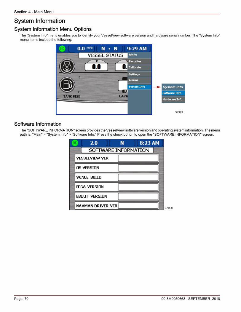
Section 4 - Main Menu
Page 70 90-8M0050668 SEPTEMBER 2010
System InformationSystem Information Menu Options
The "System Info" menu enables you to identify your VesselView software version and hardware serial number. The "System Info"menu items include the following:
Main
Favorites
Calibrate
Settings
Alarms
System Info System Info
Hardware Info
Software Info
34329
Software InformationThe "SOFTWARE INFORMATION" screen provides the VesselView software version and operating system information. The menupath is: "Main" > "System Info" > "Software Info." Press the check button to open the "SOFTWARE INFORMATION" screen.
37090
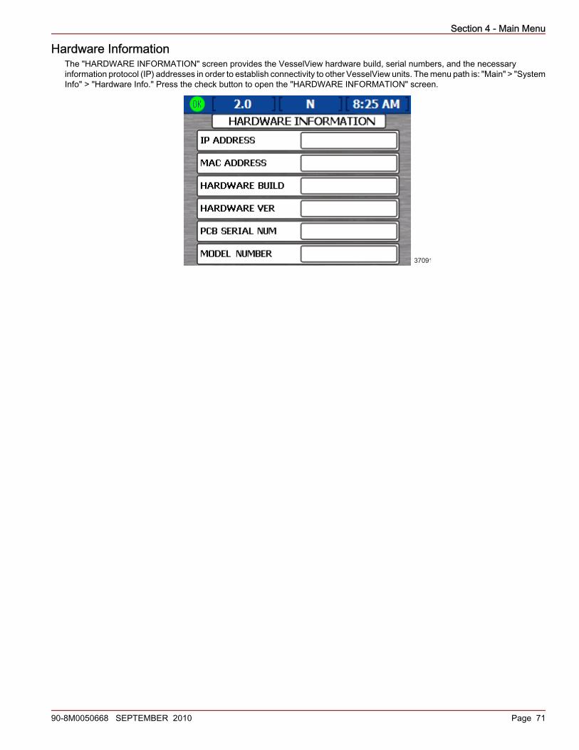
Section 4 - Main Menu
90-8M0050668 SEPTEMBER 2010 Page 71
Hardware InformationThe "HARDWARE INFORMATION" screen provides the VesselView hardware build, serial numbers, and the necessaryinformation protocol (IP) addresses in order to establish connectivity to other VesselView units. The menu path is: "Main" > "SystemInfo" > "Hardware Info." Press the check button to open the "HARDWARE INFORMATION" screen.
37091

Section 4 - Main Menu
Notes:
Page 72 90-8M0050668 SEPTEMBER 2010
Section 5 - Propulsion Menu
90-8M0050668 SEPTEMBER 2010 Page 73
Section 5 - Propulsion MenuTable of ContentsUsing Propulsion Screens ................................................... 74
Available Propulsion Screens........................................74Viewing Engine Status...................................................74Viewing Performance and Fuel......................................75
Resetting Total Fuel Used ..................................... 75Viewing Peak Performance...........................................76
Resetting Peak Values .......................................... 76Viewing Steering Position (MerCruiser Only)................76Viewing Trim Position....................................................77Viewing Tab Position (Diesel Only)...............................78Viewing Boost Pressure (Optional)................................78
Using Troll Control.........................................................79Setting Troll Control ............................................... 79
Viewing Demand and Load (Diesel only).......................80Viewing Transmission Data (Diesel only)......................80Viewing Intake Data (Diesel only)..................................81Using Cruise Control......................................................81
Setting the Cruise Control ..................................... 81Using Smart Tow...........................................................82Setting Cruise with Smart Tow......................................82
Setting Smart Tow Launch Control ....................... 83
5

Section 5 - Propulsion Menu
Page 74 90-8M0050668 SEPTEMBER 2010
Using Propulsion ScreensAvailable Propulsion Screens
IMPORTANT: The available VesselView menu items and options are dependent on the engine type, and if screens have beenmanually turned on or off.The propulsion screens display information about boat propulsion systems such as fuel, speed, and trim. Screens available fromthe propulsion menu vary according to the engine type, but may include the following:• Engine Status• Performance and Fuel• Peak Performance• Trim• Tabs• Boost• Steering• Troll• Cruise Control• Smart Tow• Demand and Load• Transmission• Intake
Viewing Engine StatusThe engine status screen shows basic operating information for up to three engines. The information displayed differs for eachengine type.
a - Port engine RPMb - Starboard engine RPMc - Engine temperatured - Oil pressuree - Battery voltagef - Water pressure
• RPM is displayed for up to three gas or diesel engines.• Speed is displayed using pitot, paddle, or GPS sensor information.• Diesel engines will display fuel flow instead of water pressure.• Estimated range is determined using the total fuel flow for all engines and the current rate at which the engines are consuming
fuel.• Total fuel used is the amount of fuel used from all fuel tanks and engines combined.
26883
a b
c
d
e
f

Section 5 - Propulsion Menu
90-8M0050668 SEPTEMBER 2010 Page 75
Viewing Performance and FuelThe performance and fuel screen shows basic operating information for up to four engines. The fourth engine allows for anadditional fuel tank display.
a - Port engine RPMb - Starboard engine RPMc - Boat speedd - Estimated rangee - Total fuel usedf - Fuel tank status
• RPM is displayed for up to three gas or diesel engines.• Speed is displayed using pitot, paddle, or GPS sensor information.• Estimated range is determined using the total fuel flow for all engines and the current rate at which the engines are consuming
fuel.• Total fuel used is the amount of fuel used from all fuel tanks and engines combined.• The fuel tank status icons display the amount and type of fuel in each tank, as well as the location of each tank.• The fuel tank color will change from green to red if the tank is below the critical level. Refer to Section 4 - Warnings for critical
fuel level adjustment.
Resetting Total Fuel Used1. Press the check button while on this screen to access the "Total Fuel Used" pop‑up screen. The pop‑up will ask you "Would
you like to Reset your Fuel Used?"
27265
Fuel used pop-up screen
2. Press the check button to reset the total fuel used or the "X" button to cancel.
26885
a b
c
de
f

Section 5 - Propulsion Menu
Page 76 90-8M0050668 SEPTEMBER 2010
Viewing Peak PerformanceThe peak performance screen shows current speed and RPM, as well as the highest speed and associated engine RPM recordedsince the last reset.
a - Actual engine RPMb - Actual boat speedc - Peak engine RPMd - Peak boat speed
• RPM is displayed for up to three gas or diesel engines.• Speed is displayed using pitot, paddle, or GPS sensor information.• Peak speed is the highest speed recorded since the last reset of peak values.• Peak engine RPM is the engine RPM associated with the highest speed since the last reset of peak values.
Resetting Peak Values1. Press the check button while on this screen to access the "peak values" pop‑up screen. The pop‑up will ask you "Would you
like to Reset your Peak Values?"
Would you like to Reset
your Peak Values?
27243
Peak values pop-up screen
2. Press the check button to reset the peak values or the "X" button to cancel.
Viewing Steering Position (MerCruiser Only)The "STEERING POSITION" screen displays the current steering position in degrees. The default steering position can be adjusted60 degrees in either direction by changing the offset. The data options on the bottom of the screen can be changed to displaydifferent data. Refer to Section 4 - Settings for more information.
a a
b
c cd27241
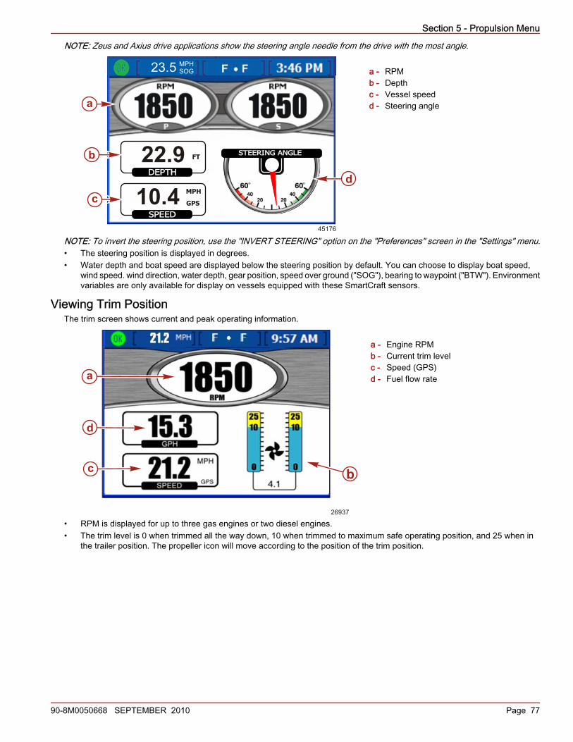
Section 5 - Propulsion Menu
90-8M0050668 SEPTEMBER 2010 Page 77
NOTE: Zeus and Axius drive applications show the steering angle needle from the drive with the most angle.
a - RPMb - Depthc - Vessel speedd - Steering angle
NOTE: To invert the steering position, use the "INVERT STEERING" option on the "Preferences" screen in the "Settings" menu.• The steering position is displayed in degrees.• Water depth and boat speed are displayed below the steering position by default. You can choose to display boat speed,
wind speed. wind direction, water depth, gear position, speed over ground ("SOG"), bearing to waypoint ("BTW"). Environmentvariables are only available for display on vessels equipped with these SmartCraft sensors.
Viewing Trim PositionThe trim screen shows current and peak operating information.
a - Engine RPMb - Current trim levelc - Speed (GPS)d - Fuel flow rate
• RPM is displayed for up to three gas engines or two diesel engines.• The trim level is 0 when trimmed all the way down, 10 when trimmed to maximum safe operating position, and 25 when in
the trailer position. The propeller icon will move according to the position of the trim position.
MPHSOG23.5
STEERING ANGLE
DEPTH
SPEED
22.9
GPS10.445176
a
b
c
d
FT
MPH
26937
a
bc
d
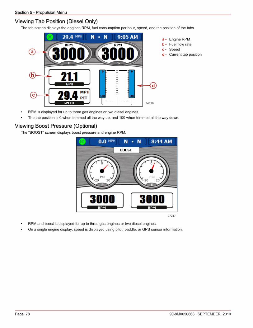
Section 5 - Propulsion Menu
Page 78 90-8M0050668 SEPTEMBER 2010
Viewing Tab Position (Diesel Only)The tab screen displays the engines RPM, fuel consumption per hour, speed, and the position of the tabs.
a - Engine RPMb - Fuel flow ratec - Speedd - Current tab position
• RPM is displayed for up to three gas engines or two diesel engines.• The tab position is 0 when trimmed all the way up, and 100 when trimmed all the way down.
Viewing Boost Pressure (Optional)The "BOOST" screen displays boost pressure and engine RPM.
27247
• RPM and boost is displayed for up to three gas engines or two diesel engines.• On a single engine display, speed is displayed using pitot, paddle, or GPS sensor information.
34267
c
d
a
b
34330
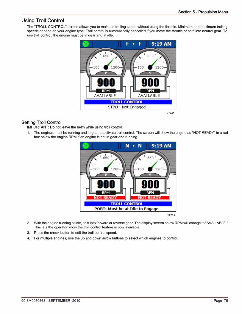
Section 5 - Propulsion Menu
90-8M0050668 SEPTEMBER 2010 Page 79
Using Troll ControlThe "TROLL CONTROL" screen allows you to maintain trolling speed without using the throttle. Minimum and maximum trollingspeeds depend on your engine type. Troll control is automatically cancelled if you move the throttle or shift into neutral gear. Touse troll control, the engine must be in gear and at idle.
AVAILABLE
STBD : Not Engaged
AVAILABLE
27741
Setting Troll ControlIMPORTANT: Do not leave the helm while using troll control.1. The engines must be running and in gear to activate troll control. The screen will show the engine as "NOT READY" in a red
box below the engine RPM if an engine is not in gear and running.
27739
2. With the engine running at idle, shift into forward or reverse gear. The display screen below RPM will change to "AVAILABLE."This lets the operator know the troll control feature is now available.
3. Press the check button to edit the troll control speed.4. For multiple engines, use the up and down arrow buttons to select which engines to control.

Section 5 - Propulsion Menu
Page 80 90-8M0050668 SEPTEMBER 2010
5. To activate the troll control, press the left or right arrow button and the engine will troll at the displayed speed. The displayscreen below RPM will change from "AVAILABLE" to "TROLLING."
TROLLING
STBD : Engaged
TROLLING
27743
6. Use the left and right arrow buttons to adjust speed up or down.
Viewing Demand and Load (Diesel only)The demand and load screen shows current percentage of load and throttle for up to two diesel engine applications.
a - Port engine RPMb - Starboard engine RPMc - Percentage of loadd - Percentage of throttle
Viewing Transmission Data (Diesel only)The transmission screen shows gear temperature and gear pressure for up to two diesel engine applications.
a - Port engine RPMb - Starboard engine RPMc - Gear temperatured - Gear pressure
34618
a b
c
d
22302220
34619
a b
c
d
22302220

Section 5 - Propulsion Menu
90-8M0050668 SEPTEMBER 2010 Page 81
• Gear temperature is displayed in degrees fahrenheit by default.• Gear pressure is displayed in PSI by default.
Viewing Intake Data (Diesel only)The intake screen displays intake temperature and supercharger boost for up to two diesel engine applications.
a - Port engine RPMb - Starboard engine RPMc - Intake temperatured - Boost
Using Cruise ControlThe "CRUISE CONTROL" screen allows you to set an engine RPM level for each engine to maintain while the cruise control isengaged. Cruise control is not available on all vessels.
a - Engine RPMb - Boat speedc - RPM set pointd - Cruise control status
• RPM is displayed for up to three engines.• Speed is displayed using pitot, paddle, or GPS sensor information.• The maximum RPM set point is the maximum engine RPM at wide‑open throttle (WOT). When cruise control is engaged, the
engine will not accelerate past this RPM level.• Cruise control status displays whether cruise control is "ENABLED" or "OFF."
Setting the Cruise ControlNOTE: If the VesselView is equipped with Smart Tow and it is enabled, you will not have the "CRUISE CONTROL" menu.IMPORTANT: Do not leave the helm while using cruise control.1. From the "CRUISE CONTROL" screen, press the check button to activate cruise control.2. Press the check button to activate the RPM set point box.3. Use the left and right arrow buttons to set the target RPM.4. Press the up arrow to activate the status box.5. Press the left or right arrow button to set the status to "Enabled."
34620
a b
c
d
22302220
26875
a
b
c
d

Section 5 - Propulsion Menu
Page 82 90-8M0050668 SEPTEMBER 2010
6. Press the check button to exit the edit mode.7. Move the remote control handle to the WOT position to reach the RPM set point.NOTE: While cruise control is enabled, adjust the RPM set point using the arrow pad; or by pressing the check button to activatethe RPM set point box and adjusting the RPM set point with the left and right arrow buttons.
Using Smart TowThe "SMART TOW" screen allows you to automatically accelerate using a preset launch profile, and to set a maximum cruisingRPM for consistent tow sport performance. Five automatic launch profiles are available. Smart Tow is not available on all vessels.
a - RPM set pointb - Boat speedc - Smart Tow status boxd - Engine RPMe - Launch profile
• The RPM set point is the target engine RPM when using Smart Tow for cruise control. The RPM set point also controls thetarget cruising engine RPM after launch.IMPORTANT: Changing the RPM set point does not affect the current launch profile selected.
• RPM "LAUNCH CONTROL" displays which profile is selected and the acceleration over time for that launch profile.• Status displays whether launch control is enabled or off.• Speed is displayed using pitot, paddle, or GPS sensor information.
Setting Cruise with Smart Tow1. From the "SMART TOW" screen, press the check button to activate the RPM set point box.2. Use the left and right arrow buttons to set a maximum RPM.3. Press the down arrow to activate the Smart Tow status box.4. To activate the cruise control, press the left or right arrow button to set the status to "ENABLED."
27744
Smart Tow cruise control screen
5. Press the check button to exit the edit mode.
LAUNCH
a b
c
d
e
27258
00.0
LAUNCH
a
b
c
d
e
27258

Section 5 - Propulsion Menu
90-8M0050668 SEPTEMBER 2010 Page 83
6. Move the remote control handle to the WOT position to reach the RPM set point.
Setting Smart Tow Launch ControlIMPORTANT: Do not leave the helm while using Smart Tow launch control.1. From the "SMART TOW" screen, press the check button to activate the RPM set point box.2. Use the left and right arrow buttons to set a maximum RPM.3. Press the down arrow to activate the Smart Tow status box.4. Press the left or right arrow button to set the status from "ENABLED" to "LAUNCH."5. Press the down arrow to activate the "LAUNCH CONTROL" box.6. Press the left or right arrow button to select the launch profile best suited to your towing application. Five profiles are available
ranging from the least aggressive acceleration (Profile 1) to the most aggressive acceleration (Profile 5).
27255
Launch profiles
7. Press the check button to exit the edit mode.8. Move the throttle to WOT to begin the launch. The "STATUS" box displays "ACTIVE" while the launch is in progress.

Section 5 - Propulsion Menu
Notes:
Page 84 90-8M0050668 SEPTEMBER 2010
Section 6 - Vessel Menu
90-8M0050668 SEPTEMBER 2010 Page 85
Section 6 - Vessel MenuTable of ContentsUsing Vessel Screens.......................................................... 86
Checking Vessel Status ................................................ 86Checking Tank Status .................................................. 87
Viewing Steering Position (MerCruiser Only) ............... 88Viewing Generator Data ............................................... 88
6

Section 6 - Vessel Menu
Page 86 90-8M0050668 SEPTEMBER 2010
Using Vessel ScreensIMPORTANT: The available screens listed in the VesselView menu of each category is determined by the vessel setup, enginetype, if screens have been manually turned on or off, and other components connected to the communication network. Forexample: VesselView will not show tab information for a vessel without tabs. Different engine types (sterndrive versus an outboard)will have different screens. Refer to Section 3 - Available VesselView Display Screens for a list of the engine types and theirassociated screens.The vessel screens display information about vessel performance, speed, status of tanks, generator, heating, and air conditioning.Screens available from the vessel menu vary according to the engine type.
Vessel
Perf & Fuel
Vessel Status
Speed
Tank Status
Generator
Steer Position
32632
Checking Vessel StatusThe "VESSEL STATUS" screen displays engine run time for up to three engines, as well as fuel information.
a - Engine run timeb - Fuel tank levelsc - Fuel tank sized - Total fuel remaininge - Total fuel capacity
• Engine run time is displayed in hours for up to three engines.• Fuel remaining is displayed in U.S. gallons by default. Refer to Section 4 - Units 2 to change the units.• Capacity shows the total fuel capacity of all available fuel tanks.• The fuel remaining in each tank is displayed in the fuel tank gauge icon. The fuel tank color will change from green to red if
the tank is below the critical level.
d
e
a
b bc
27291

Section 6 - Vessel Menu
90-8M0050668 SEPTEMBER 2010 Page 87
Checking Tank StatusThe "TANK STATUS" screen displays the contents and level of each tank, up to two tanks for each engine. Refer to Section 2 -Setup and Calibration to configure the tanks displayed on this screen.
a - Port 1 (P1); gasolineb - Port 2 (P2); wastec - Starboard 1 (S1); gasolined - Starboard 2 (S2); water
• Each tank gauge icon shows the type of tank: water, waste, fuel, or oil.• Tanks are labeled by their locations. Available labels are:
• Starboard 1 (S1), starboard 2 (S2), starboard 3 (S3), starboard aft (SA), or starboard forward (SF)• Port 1 (P1), port 2 (P2), port 3 (P3), port aft (PA), or port forward (PF)• Center 1 (C1), center 2 (C2), center 3 (C3), center aft (CA), or center forward (CF)• The contents of each tank are color coded:
• Blue represents water• Brown represents waste• Green represents gasoline or diesel fuel• Black represents oil• Red represents critical fuel level
NOTE: Press the check button to display a dialog box showing the tank colors and tank contents. Press the "X" buttonto close the dialog box.
27290
Tank status pop-up window
26933
a d
cb

Section 6 - Vessel Menu
Page 88 90-8M0050668 SEPTEMBER 2010
Viewing Steering Position (MerCruiser Only)The "STEERING POSITION" screen displays the current steering position in degrees. The default steering position can be adjusted60 degrees in either direction by changing the offset. The data options on the bottom of the screen can be changed to displaydifferent data. Refer to Section 4 - Settings for more information.NOTE: Zeus and Axius drive applications show the steering angle needle from the drive with the most angle.
a - RPMb - Depthc - Vessel speedd - Steering angle
NOTE: To invert the steering position, use the "INVERT STEERING" option on the "Preferences" screen in the "Settings" menu.• The steering position is displayed in degrees.• Water depth and boat speed are displayed below the steering position by default. You can choose to display boat speed,
wind speed. wind direction, water depth, gear position, speed over ground ("SOG"), bearing to waypoint ("BTW"). Environmentvariables are only available for display on vessels equipped with these SmartCraft sensors.
Viewing Generator DataVesselView displays operating information for your SmartCraft‑enabled Onan or Kohler generator on the "GENERATOR" screen.NOTE: The generator must be capable of SmartCraft protocol language for this display to function. If the generator is not SmartCraftsupported, you can turn the generator display off . The menu path is: "Main" > "Settings" > "Screen Options" > "Pages On/Off" >"Vessel."
a - Generator output voltage (120 V or 240 V)b - Generator run hoursc - Output frequency (Hz)d - Generator engine temperaturee - Oil pressuref - Generator cranking battery voltageg - Run indicator
• The generator manufacturer's name is automatically displayed at the top of the screen.• If the generator is running, a green indicator appears next to "RUN." Otherwise, a red indicator appears next to "STOP."• The run time displays the running time of the generator to the tenth of an hour up to 999.9 hours, then in whole hours to 99,999
hours.• Battery voltage and engine temperature are displayed with both Onan and Kohler generators.• Oil pressure is available with Onan generators only.
MPHSOG23.5
STEERING ANGLE
DEPTH
SPEED
22.9
GPS10.445176
a
b
c
d
FT
MPH
120 60
140 8.7 12.4F PSI Vo
a
b
c
d e f
5.0
27275
g

Section 7 - Environment and Navigation Menu
90-8M0050668 SEPTEMBER 2010 Page 89
Section 7 - Environment and Navigation MenuTable of ContentsUsing Environment and Navigation Screens........................ 90
Environment and Navigation Screens...........................90Viewing Depth and Water Temperature........................90
Setting Depth Alerts .............................................. 91Viewing Trip Log Information.........................................92
Resetting Trip Log Amounts .................................. 92Viewing Fuel to Waypoint Data......................................93Viewing Navigation Data................................................93
Viewing Autopilot Data (Zeus and Axius Only)..............94Standby ................................................................. 94Track to Waypoint ................................................. 95Waypoint Sequence .............................................. 95Skyhook Station Keeping ...................................... 97VesselView Skyhook Screens ............................... 99Joystick Screen ................................................... 100
7
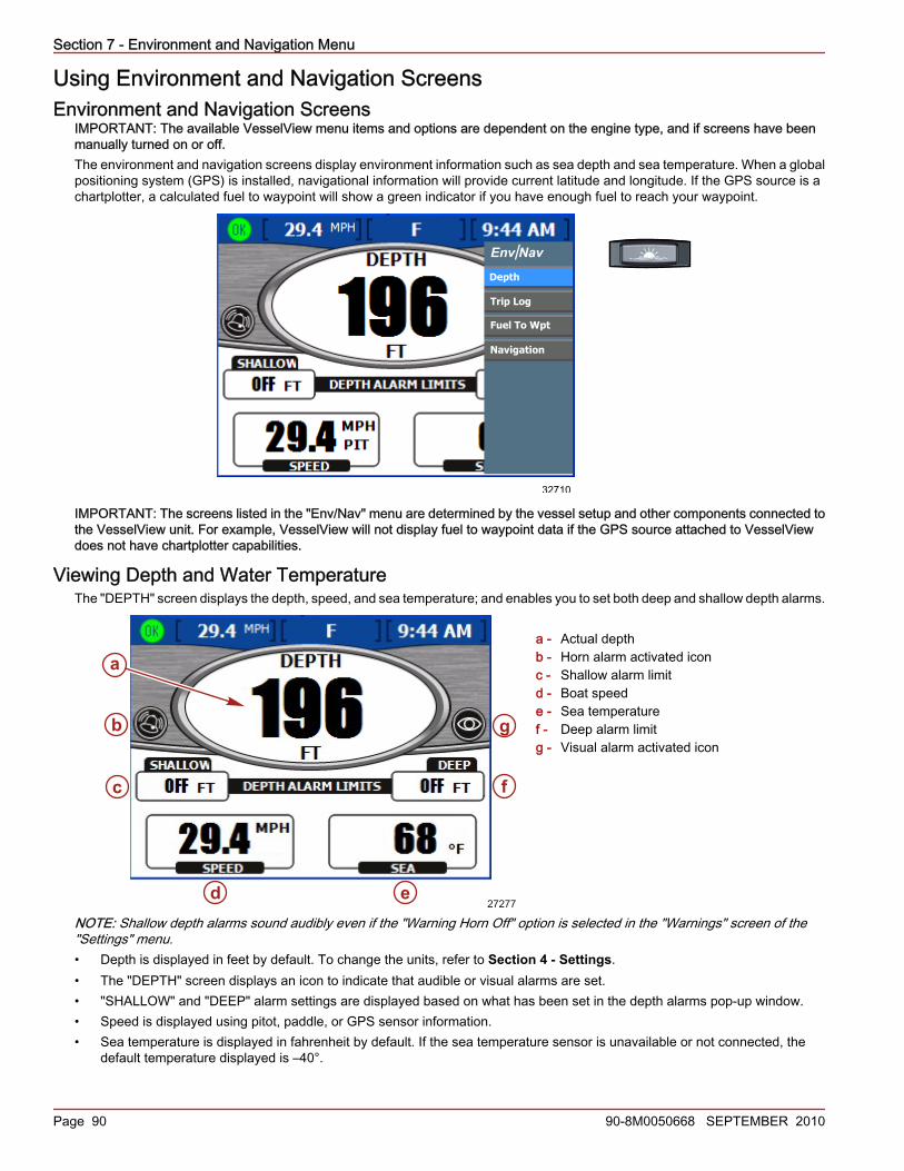
Section 7 - Environment and Navigation Menu
Page 90 90-8M0050668 SEPTEMBER 2010
Using Environment and Navigation ScreensEnvironment and Navigation Screens
IMPORTANT: The available VesselView menu items and options are dependent on the engine type, and if screens have beenmanually turned on or off.The environment and navigation screens display environment information such as sea depth and sea temperature. When a globalpositioning system (GPS) is installed, navigational information will provide current latitude and longitude. If the GPS source is achartplotter, a calculated fuel to waypoint will show a green indicator if you have enough fuel to reach your waypoint.
Env Nav
Depth
Trip Log
Navigation
Fuel To Wpt
/
32710
IMPORTANT: The screens listed in the "Env/Nav" menu are determined by the vessel setup and other components connected tothe VesselView unit. For example, VesselView will not display fuel to waypoint data if the GPS source attached to VesselViewdoes not have chartplotter capabilities.
Viewing Depth and Water TemperatureThe "DEPTH" screen displays the depth, speed, and sea temperature; and enables you to set both deep and shallow depth alarms.
a - Actual depthb - Horn alarm activated iconc - Shallow alarm limitd - Boat speede - Sea temperaturef - Deep alarm limitg - Visual alarm activated icon
NOTE: Shallow depth alarms sound audibly even if the "Warning Horn Off" option is selected in the "Warnings" screen of the"Settings" menu.• Depth is displayed in feet by default. To change the units, refer to Section 4 - Settings.• The "DEPTH" screen displays an icon to indicate that audible or visual alarms are set.• "SHALLOW" and "DEEP" alarm settings are displayed based on what has been set in the depth alarms pop‑up window.• Speed is displayed using pitot, paddle, or GPS sensor information.• Sea temperature is displayed in fahrenheit by default. If the sea temperature sensor is unavailable or not connected, the
default temperature displayed is –40°.
a
b
c
d e
f
g
27277
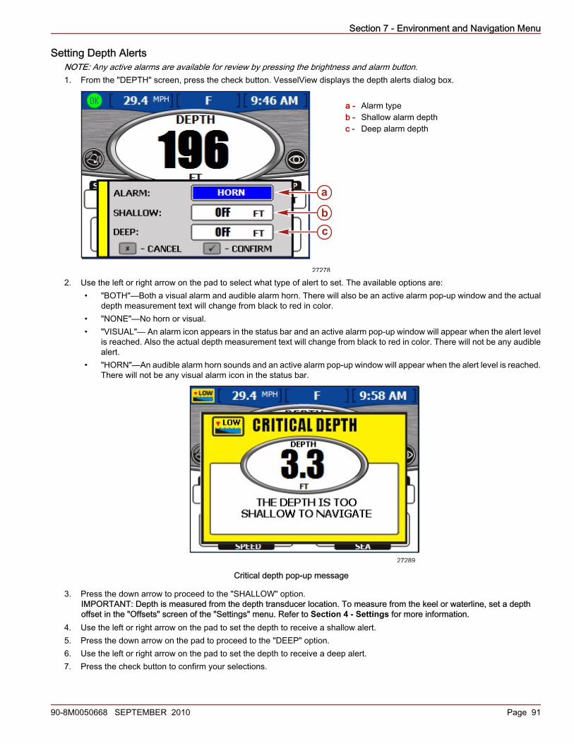
Section 7 - Environment and Navigation Menu
90-8M0050668 SEPTEMBER 2010 Page 91
Setting Depth AlertsNOTE: Any active alarms are available for review by pressing the brightness and alarm button.1. From the "DEPTH" screen, press the check button. VesselView displays the depth alerts dialog box.
a - Alarm typeb - Shallow alarm depthc - Deep alarm depth
2. Use the left or right arrow on the pad to select what type of alert to set. The available options are:• "BOTH"—Both a visual alarm and audible alarm horn. There will also be an active alarm pop‑up window and the actual
depth measurement text will change from black to red in color.• "NONE"—No horn or visual.• "VISUAL"— An alarm icon appears in the status bar and an active alarm pop‑up window will appear when the alert level
is reached. Also the actual depth measurement text will change from black to red in color. There will not be any audiblealert.
• "HORN"—An audible alarm horn sounds and an active alarm pop‑up window will appear when the alert level is reached.There will not be any visual alarm icon in the status bar.
27289
Critical depth pop-up message
3. Press the down arrow to proceed to the "SHALLOW" option.IMPORTANT: Depth is measured from the depth transducer location. To measure from the keel or waterline, set a depthoffset in the "Offsets" screen of the "Settings" menu. Refer to Section 4 - Settings for more information.
4. Use the left or right arrow on the pad to set the depth to receive a shallow alert.5. Press the down arrow on the pad to proceed to the "DEEP" option.6. Use the left or right arrow on the pad to set the depth to receive a deep alert.7. Press the check button to confirm your selections.
a
bc
27278

Section 7 - Environment and Navigation Menu
Page 92 90-8M0050668 SEPTEMBER 2010
Viewing Trip Log InformationThe "TRIP LOG" screen displays the time, distance traveled, and average performance since the last reset.
a - Trip timeb - Distance traveledc - Fuel usedd - Fuel economye - Fuel remainingf - Average speedg - Engine run time
• Trip time is the amount of time the VesselView has been operated since the last reset.• Fuel economy displays the average fuel use since the last reset. By default, this is calculated in miles per gallon.• Fuel used is the total amount of fuel used from all tanks since the last reset.• Average speed displays the average boat speed since the last reset.• Distance shows the distance traveled since the last reset.• Run time shows the total hours the engines have been running since the last reset.• Fuel remaining is the total fuel amount left in all tanks. This amount cannot be reset.
Resetting Trip Log Amounts1. From the "TRIP LOG" screen, press the check button. VesselView displays the reset dialog box.
34540
ALL VALUES
Trip log reset pop-up window
2. Press the check button to confirm your choice to reset the trip log screen, or press the "X" button to cancel the reset.NOTE: The fuel remaining value cannot be reset through this menu.
a
b
c d e
f
g
27280

Section 7 - Environment and Navigation Menu
90-8M0050668 SEPTEMBER 2010 Page 93
Viewing Fuel to Waypoint DataThe "FUEL TO WAYPOINT" screen displays dynamic travel information with a GPS unit connected. The range to waypoint willshow the estimated distance the engines will run at the current speed with the fuel available. If the distance to waypoint is lessthan the range to waypoint, the range distance will be green. If the distance to waypoint is more than the range to waypoint, therange distance will be red. For the most accurate data, maintain bearing to the waypoint destination.
a - Range to waypointb - Distance to waypointc - Bearing to waypointd - Fuel to waypointe - Speed over groundf - Total fuel flow rateg - Fuel economy
• If you have set a waypoint on your GPS unit, the distance to waypoint (DTW) option shows the remaining distance.• The speed over ground (SOG) option displays the boat's speed as calculated by the GPS unit.• The fuel to waypoint (FTW) will display the estimated amount of fuel needed to reach the waypoint.• Displays the total fuel flow rate and fuel economy.
Viewing Navigation DataThe "NAVIGATION" screen displays information from a connected GPS unit and is available on gasoline engines only.
a - Latitude location coordinateb - Longitude location coordinatec - Distance to waypoint (DIST WPT)d - Speed over ground (SOG)e - GPS heading
• Latitude and longitude are displayed based on available GPS data.• If you have set a waypoint, the "DIST WPT" box shows the remaining distance.• The "SOG" box displays the boat's speed as calculated by the GPS unit. Due to wind and current, this value may differ from
the speed in the water.• The heading is calculated by the GPS unit. Due to wind and current, this heading may differ from your course over ground.
a
b c
d
e
f
g
27284
LAT
LON
DIST WPT SOG HEADING1.5 10.0 23MI MPH TO
NAVIGATION
20 20.328 S157 44.502 W
o
o
a
b
c d e 27333

Section 7 - Environment and Navigation Menu
Page 94 90-8M0050668 SEPTEMBER 2010
Viewing Autopilot Data (Zeus and Axius Only)Autopilot is a drive integrated system that utilizes a GPS receiver, a customer‑supplied NMEA 0183 compatible chartplotter, aninertial measurement unit (IMU), the electronic helm in combination with the VesselView, joystick control, and the Precision Pilotor Axius trackpad. Refer to your power package owner's manual for a complete understanding of the Autopilot features andoperation.Autopilot indicates the drive location (angle) with a needle colored red, black, and green. Red indicates the port drive, greenindicates the starboard drive, and black indicates the center drive. The center drive color can vary with red or green, dependingon the configuration and number of VesselView's installed.Using the trackpad, the operator is able to use waypoints, tracking along a desired path; the boat will navigate itself along thispath.NOTE: Autopilot will not initiate turns when track waypoint mode is engaged. Turn features are only available in auto headingmode.• Autopilot functions are controlled through the Precision Pilot trackpad or Axius trackpad only.• When autopilot is engaged, "AUTOPILOT" screens appear on the VesselView for three seconds unless calibrated otherwise.• The response level is used to change how aggressive corrections respond. "1" is for calm conditions, "2" is for moderate
conditions, and "3" is for severe conditions.
a - Response levelb - Compass headingc - Drive angle referenced - RPMe - Autopilot icon
• Pressing any button on the VesselView cancels the "AUTOPILOT" screen, unless the "AUTOPILOT" screen was selectedfrom the VesselView "Environment and Navigation" menu.
• The "TURN" buttons on the Precision Pilot or Axius trackpad provide a 10° course correction for each press to the port orstarboard.
• The joystick provides a 1° course correction for each press to the port or starboard.
The steering wheel feels locked into a detent when "AUTO" or "TRACK" are engaged. Approximately 3.4–4.5 kg (8–10 lb) of forceis required to overcome this detent. Manually overcoming the steering wheel's detent force automatically puts the autopilot intostandby mode.
Standby• In standby mode, the display shows a digital compass value and the angle of the drives when engaged.• The compass value is the actual heading from the IMU.
34338
a
b
c
d
e
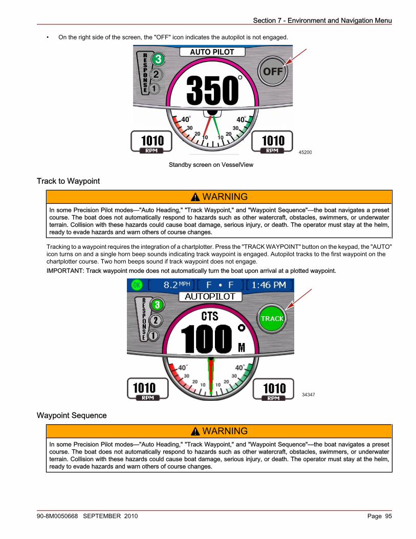
Section 7 - Environment and Navigation Menu
90-8M0050668 SEPTEMBER 2010 Page 95
• On the right side of the screen, the "OFF" icon indicates the autopilot is not engaged.
45200
OFF
Standby screen on VesselView
Track to Waypoint
! WARNINGIn some Precision Pilot modes—"Auto Heading," "Track Waypoint," and "Waypoint Sequence"—the boat navigates a presetcourse. The boat does not automatically respond to hazards such as other watercraft, obstacles, swimmers, or underwaterterrain. Collision with these hazards could cause boat damage, serious injury, or death. The operator must stay at the helm,ready to evade hazards and warn others of course changes.
Tracking to a waypoint requires the integration of a chartplotter. Press the "TRACK WAYPOINT" button on the keypad, the "AUTO"icon turns on and a single horn beep sounds indicating track waypoint is engaged. Autopilot tracks to the first waypoint on thechartplotter course. Two horn beeps sound if track waypoint does not engage.IMPORTANT: Track waypoint mode does not automatically turn the boat upon arrival at a plotted waypoint.
34347
Waypoint Sequence
! WARNINGIn some Precision Pilot modes—"Auto Heading," "Track Waypoint," and "Waypoint Sequence"—the boat navigates a presetcourse. The boat does not automatically respond to hazards such as other watercraft, obstacles, swimmers, or underwaterterrain. Collision with these hazards could cause boat damage, serious injury, or death. The operator must stay at the helm,ready to evade hazards and warn others of course changes.

Section 7 - Environment and Navigation Menu
Page 96 90-8M0050668 SEPTEMBER 2010
When the boat enters a waypoint arrival zone as indicated by the chartplotter, a short horn beep sounds and the "WAYPOINTSEQUENCE" button light on the keypad starts blinking to inform the operator to make a turn. If the waypoint sequencing modehas not been engaged, the "WAYPOINT SEQUENCING" icon light blinks at the arrival zone.
34348
VesselView displays a pop‑up screen advising the operator to acknowledge the waypoint arrival. The operator must determine ifit is safe to turn the boat.
34350

Section 7 - Environment and Navigation Menu
90-8M0050668 SEPTEMBER 2010 Page 97
Press the "WAYPOINT SEQUENCE" button to acknowledge that it is safe to automatically turn the boat and maneuver to the newcourse. If the waypoint is not acknowledged, the boat continues on its current heading. If you are not in a set waypoint arrivalzone, the waypoint sequencing mode starts auto sequencing to the waypoints in the route. Acknowledge that you understand theinformation presented by the pop‑up screen warning and press the check button. At the end of the track waypoint route, you mustinput a new route or take control of the boat. Otherwise the boat reverts to auto heading mode and continues on its last courseheading.
34352
Skyhook Station KeepingThe vessel may be equipped with the Skyhook Station Keeping feature. This system utilizes global positioning system technology(GPS) and an electronic compass to automatically control shifting, throttling, and steering to maintain heading and approximateposition. This feature can be helpful when waiting for space near a fuel dock, waiting for bridges to open, or when the water is toodeep for an anchor.Skyhook does not maintain an exact fixed position, but rather will hold the vessel in a fixed compass heading within an area. Thesize of this area is affected by the accuracy of the GPS satellite system, the satellite signal quality, the physical position of thesatellites relative to the receiver, solar flares and the proximity of the receiver on the boat to large structures and trees.Under typical operating conditions Skyhook is capable of holding the vessel within a radius of 10 meters (30 feet). However, thisdistance may increase to a radius of 30 meters (100 feet). Do not engage Skyhook when the vessel is within 30 meters(100 feet) of any obstacle, obstruction, dock, bridge, vessel, swimmer, etc.While in Skyhook, it is essential the captain remain at the helm prepared to take control of the vessel due to changing conditionssuch as:• • A swimmer or another vessel approaches the vessel• • Skyhook satellite signal is lost and automatically disengages• •The size of the area which the vessel is being held in increases
Before engaging Skyhook, the captain should brief all passengers on how Skyhook operates. Direct them to stay out of the water,not to sit or stand where they could fall overboard, and to be alert for any sudden shifts in the vessel’s position. Occasionally theSkyhook system may apply a brief surge in power to hold a position. If passengers are not prepared for this occurrence they mayloose their balance and fall.
! WARNINGA rotating propeller, a moving vessel, or a device attached to a moving vessel can cause serious injury or death to people inthe water. When Skyhook is engaged, the propellers rotate and the vessel moves to maintain the position of the vessel. Stopthe engines immediately whenever anyone is in the water near the vessel.
Skyhook will not engage unless the joystick and control levers are in neutral. When Skyhook is engaged, the propellers turn but,the rotation may not be obvious. Ensure that no one is in the water near the vessel within 30 meters (100 feet) and the passengersare secure when the engines are running.When Skyhook is engaged the captain must:• Remain at the helm• Watch closely for anyone in the water near the vessel• Disengage Skyhook if anyone enters the water or approaches the vessel from the water

Section 7 - Environment and Navigation Menu
Page 98 90-8M0050668 SEPTEMBER 2010
• Watch for approaching vessels and disengage Skyhook if any vessel is on an intercept course
Skyhook system response will change with wind and current conditions. Familiarize yourself with how best to position your vesselregarding the speed and direction of wind and current. When you place the bow into the wind, the Skyhook system response issmoother. Experiment to determine what works best for your vessel in various situations.Occasionally the GPS signal may weaken or become temporarily unavailable. When this happens Skyhook will sound an alarmand automatically disengage. The drives will return to neutral and the vessel will drift with the wind and current. You must be readyto take control of the helm at all times.IMPORTANT: Activities in the water near the vessel while Skyhook is engaged may result in injury or death. The operator andpassengers should read and observe the safety warning labels on the vessel before Skyhook is engaged.The following safety warning labels are located on the vessel for reference. Contact the engine manufacturer for replacementsafety warning labels if they are missing, damaged, or cannot be read
33798
8M0034159
Label near the Precision Pilot trackpad
33824
Label in the vicinity of the transom boarding area

Section 7 - Environment and Navigation Menu
90-8M0050668 SEPTEMBER 2010 Page 99
VesselView Skyhook Screens• A warning will be displayed on the VesselView screen prior to Skyhook engagement.
34354
• A single beep will be heard when engaging Skyhook mode. The display shows the drive location as different colors: red forport, black for center, and green for starboard.
Triple engine power package displaya - Response levelb - Skyhook engaged "SH"c - Starboard drive location (green)d - Center drive location (black)e - Port drive location (red)f - Compass heading
• A "NOTICE" pop‑up screen may be seen for a few seconds after engaging skyhook. The information on the pop‑up advisesoptimal performance occurs when drives are fully trimmed down and to adjust the trim position.
NOTICEADJUST TRIM POSITION
Optimal PerformaceOccurs When DrivesAre Fully Trimmed Down
45156
• A single beep sounds when the Skyhook is disengaged or the GPS signal is lost.
45154
a
f
e c
bSH
0.1 MPHSOG FF F
d
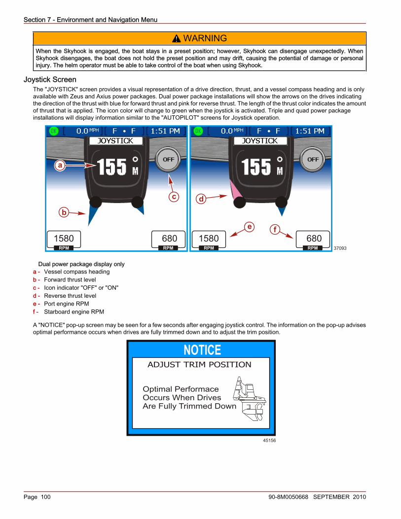
Section 7 - Environment and Navigation Menu
Page 100 90-8M0050668 SEPTEMBER 2010
! WARNINGWhen the Skyhook is engaged, the boat stays in a preset position; however, Skyhook can disengage unexpectedly. WhenSkyhook disengages, the boat does not hold the preset position and may drift, causing the potential of damage or personalinjury. The helm operator must be able to take control of the boat when using Skyhook.
Joystick ScreenThe "JOYSTICK" screen provides a visual representation of a drive direction, thrust, and a vessel compass heading and is onlyavailable with Zeus and Axius power packages. Dual power package installations will show the arrows on the drives indicatingthe direction of the thrust with blue for forward thrust and pink for reverse thrust. The length of the thrust color indicates the amountof thrust that is applied. The icon color will change to green when the joystick is activated. Triple and quad power packageinstallations will display information similar to the "AUTOPILOT" screens for Joystick operation.
Dual power package display onlya - Vessel compass headingb - Forward thrust levelc - Icon indicator "OFF" or "ON"d - Reverse thrust levele - Port engine RPMf - Starboard engine RPM
A "NOTICE" pop‑up screen may be seen for a few seconds after engaging joystick control. The information on the pop‑up advisesoptimal performance occurs when drives are fully trimmed down and to adjust the trim position.
NOTICEADJUST TRIM POSITION
Optimal PerformaceOccurs When DrivesAre Fully Trimmed Down
45156
a
b
c d
37093
1580RPM
1580RPM
680RPM
680RPM
e f
Section 8 - Glossary of Terms
90-8M0050668 SEPTEMBER 2010 Page 101
Section 8 - Glossary of TermsTable of ContentsVesselView Systems Terminology..................................... 102
8
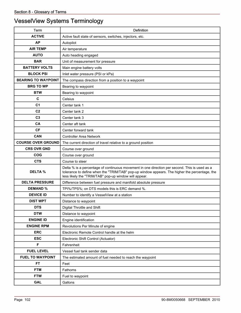
Section 8 - Glossary of Terms
Page 102 90-8M0050668 SEPTEMBER 2010
VesselView Systems TerminologyTerm Definition
ACTIVE Active fault state of sensors, switches, injectors, etc.AP Autopilot
AIR TEMP Air temperatureAUTO Auto heading engagedBAR Unit of measurement for pressure
BATTERY VOLTS Main engine battery voltsBLOCK PSI Inlet water pressure (PSI or kPa)
BEARING TO WAYPOINT The compass direction from a position to a waypointBRG TO WP Bearing to waypoint
BTW Bearing to waypointC Celsius
C1 Center tank 1C2 Center tank 2C3 Center tank 3CA Center aft tankCF Center forward tank
CAN Controller Area NetworkCOURSE OVER GROUND The current direction of travel relative to a ground position
CRS OVR GND Course over groundCOG Course over groundCTS Course to steer
DELTA %Delta % is a percentage of continuous movement in one direction per second. This is used as atolerance to define when the "TRIM/TAB" pop‑up window appears. The higher the percentage, theless likely the "TRIM/TAB" pop‑up window will appear.
DELTA PRESSURE Difference between fuel pressure and manifold absolute pressureDEMAND % TPI%/TPS%; on DTS models this is ERC demand %.DEVICE ID Number to identify a VesselView at a stationDIST WPT Distance to waypoint
DTS Digital Throttle and ShiftDTW Distance to waypoint
ENGINE ID Engine identificationENGINE RPM Revolutions Per Minute of engine
ERC Electronic Remote Control handle at the helmESC Electronic Shift Control (Actuator)
F FahrenheitFUEL LEVEL Vessel fuel tank sender data
FUEL TO WAYPOINT The estimated amount of fuel needed to reach the waypointFT Feet
FTM FathomsFTW Fuel to waypointGAL Gallons

Section 8 - Glossary of Terms
90-8M0050668 SEPTEMBER 2010 Page 103
Term DefinitionGPH Gallons per hourGPS Global Positioning System
GUARDIAN Engine Guardian Strategy is active causing a forced reduction in available powerHEAD TMP Cylinder head temperature (F or C)
HELM ID Number to identify the station the VesselView is being installed onIGL Empirical gallonsJS JoystickKM Kilometers
KMH Kilometers per hourKNOTS Unit of measurement for speed
KPA KilopascalKPL Kilometers per literLIT LitersLPH Liters per hourMet MetersMil Miles
MPG Miles per gallonMPH Miles per hourNM Nautical mile
NMEA 0183 A combined electrical and data specification for communication between marine electronic devicesand GPS receivers
NMPG Nautical miles per gallonNUM ENGINES Number of engines on the vessel
NA Not availableOFF Not engaged
OIL PSI Engine oil pressure (PSI or kPa)P1 Port tank 1P2 Port tank 2P3 Port tank 3PA Port aft tankPF Port forward tank
PADDLE WHEEL Data used to calculate vessel speed (frequency in hertz)PITOT Pitot pressure sensor data for vessel speed calculations
PORTCNTR Port centerPSI Pounds per square inch
RANGE TO WAYPOINT The estimated distance the engines will run at the current speed with the fuel availableRTW Range to waypointS1 Starboard tank 1S2 Starboard tank 2S3 Starboard tank 3SA Starboard aft tankSF Starboard forward tank

Section 8 - Glossary of Terms
Page 104 90-8M0050668 SEPTEMBER 2010
Term DefinitionSH Skyhook
SHIFT Neutral or in gear positionSOG Speed over ground
SPD OVR GRD Speed over groundSPEED OVER GROUND The speed at which the vessel is moving relative to the earth's surface
STBD StarboardSTBY Standby
STBDCNTR Starboard centerTEMP Temperature
TRACK GPS mode engagedTRIM Trim sender data
USB MEMORY STICK Memory device used to save and load VesselView configuration dataWOT Wide‑open throttle

Section 9 - Customer Assistance Information
90-8M0050668 SEPTEMBER 2010 Page 105
Section 9 - Customer Assistance InformationTable of ContentsProduct Repair and Service................................................ 106Service Away from Home................................................... 106Parts and Accessories Inquiries......................................... 106Service Assistance............................................................. 106
Mercury Marine Service Offices......................................... 106Marine Repair Logistics...................................................... 107Local Repair Service.......................................................... 107Service Away From Home.................................................. 107
9

Section 9 - Customer Assistance Information
Page 106 90-8M0050668 SEPTEMBER 2010
Product Repair and ServiceAlways return the product to your local authorized dealer should the need for service arise. Only authorized dealers havefactory‑trained mechanics with the knowledge, special tools, equipment, and genuine parts and accessories to properly serviceyour engine should the need occur.
Service Away from HomeIf you are away from your local dealer and the need arises for service, contact the nearest authorized dealer. Refer to the YellowPages of the telephone directory. If, for any reason, you cannot obtain service, contact the nearest Mercury Marine Service Office.
Parts and Accessories InquiriesAll inquiries concerning genuine replacement parts and accessories should be directed to your local authorized dealer. The dealerhas the necessary information to order parts and accessories for you. When inquiring on parts and accessories, the dealer requiresthe model and serial number to order the correct parts.
Service AssistanceYour satisfaction with your outboard product is very important to your dealer and to us. If you ever have a problem, question orconcern about your outboard product, contact your dealer or any authorized Mercury Marine dealership. If additional assistanceis required, take these steps.1. Talk with the dealership's sales manager or service manager. If this has already been done, then contact the owner of the
dealership.2. Should you have a question, concern, or problem that cannot be resolved by your dealership, please contact Mercury Marine
Service Office for assistance. Mercury Marine will work with you and your dealership to resolve all problems.The following information will be needed by the service office:• Your name and address• Daytime telephone number• Model and serial number of your outboard• The name and address of your dealership• Nature of problem
Mercury Marine Service OfficesFor assistance, call, fax, or write. Please include your daytime telephone number with mail and fax correspondence.
United States, Canada
Telephone English ‑ (920) 929‑5040Français ‑ (905) 636‑4751
Mercury MarineW6250 W. Pioneer RoadP.O. Box 1939Fond du Lac, WI 54936-1939Fax English ‑ (920) 929‑5893
Français ‑ (905) 636‑1704Website www.mercurymarine.com
Australia, PacificTelephone (61) (3) 9791‑5822 Brunswick Asia Pacific Group
132-140 Frankston RoadDandenong, Victoria 3164Australia
Fax (61) (3) 9706‑7228
Europe, Middle East, AfricaTelephone (32) (87) 32 • 32 • 11 Brunswick Marine Europe
Parc Industriel de Petit-RechainB-4800 Verviers,Belgium
Fax (32) (87) 31 • 19 • 65

Section 9 - Customer Assistance Information
90-8M0050668 SEPTEMBER 2010 Page 107
Mexico, Central America, South America, CaribbeanTelephone (954) 744‑3500 Mercury Marine
11650 Interchange Circle NorthMiramar, FL 33025U.S.A.
Fax (954) 744‑3535
JapanTelephone 072‑233‑8888 Kisaka Co., Ltd.
4-130 Kannabecho Sakai-shi Sakai-ku5900984 Osaka,Japan
Fax 072‑233‑8833
Asia, SingaporeTelephone (65) 65466160 Brunswick Asia Pacific Group
T/A Mercury Marine Singapore Pte Ltd29 Loyang DriveSingapore, 508944
Fax (65) 65467789
Marine Repair LogisticsCummins MerCruiser Diesel offers Marine Repair Logistics (MeRL) as a concierge service during the warranty period for yournew Zeus and Axius equipped vessel. MeRL is a proactive 24 x 7 x 365 team offering premium global service focused on reducingvessel repair cycle time. MeRL can assist in finding an authorized dealer/distributor for any of your service needs. ContactingMeRL will put you in touch with a Marine Specialist who will provide personal attention to the entire service event.Marine Repair Logistics is available in the USA as a toll free call.
Marine Repair Logistics Phone NumbersUSA only Outside of the USA
1‑866‑549‑6458 +1‑843‑329‑5735
You may also call 1-800-DIESELS to locate your nearest distributor.
Local Repair ServiceAlways return your Cummins MerCruiser Diesel (CMD) powered boat to your authorized dealer/distributor should the need forservice arise. Only the dealer/distributor has the factory‑trained mechanics, knowledge, special tools and equipment, and thegenuine Cummins/Mercury Marine parts and accessories to properly service your engine and drive should the need occur. Theyknow your engine and drive best. Contact 1‑800‑DIESELS to locate your closest distributor.
Service Away From HomeIf you are away from your local dealer and the need arises for service, contact the nearest Cummins MerCruiser Diesel AuthorizedRepair Facility. Refer to the Yellow Pages of the telephone directory or by using the service locator on the Cummins MerCruiserDiesel website (www.cmdmarine.com). If, for any reason, you cannot obtain service, contact the nearest Regional Service Center.Outside the United States and Canada, contact the nearest Marine Power International Service Center.