a biochar field trial and demonstration project … · technical report . uced 2015/16-05 . a ... a...
TRANSCRIPT

TECHNICAL REPORT UCED 2015/16-05
A BIOCHAR FIELD TRIAL AND DEMONSTRATION PROJECT IN EUREKA, NEVADA
TASK 1: ENGINEERING ASSESSMENT OF PYROLYSIS
PROCESS AND PRODUCTIONS
UNIVERSITY OF NEVADA, RENO

A Biochar Field Trial and Demonstration Project in Eureka, Nevada Task 1: Engineering Assessment of Pyrolysis Process and Productions
12/28/2015
ii
A BIOCHAR FIELD TRIAL AND DEMONSTRATION PROJECT IN EUREKA, NEVADA
TASK 1: ENGINEERING ASSESSMENT OF PYROLYSIS
PROCESS AND PRODUCTIONS
Curtis Robins
and
Frederick Steinmann (Project Overview)
Curtis Robins is an Assistant Research Engineer in the Division of Atmospheric Services at the
Desert Research Institute. Frederick Steinmann is an Assistant Research Professor with the University Center for
Economic Development, College of Business at the University of Nevada, Reno.
December 2015

A Biochar Field Trial and Demonstration Project in Eureka, Nevada Task 1: Engineering Assessment of Pyrolysis Process and Productions
12/28/2015
iii
This publication, A Biochar Field Trial and Demonstration Project in Eureka, Nevada Task 1: Engineering Assessment of Pyrolysis Process and Productions, was published by the University Center for Economic Development in the College of Business at the University of Nevada, Reno. This publication's statements, findings, conclusions, recommendations, and/or data represent solely the findings and views of the authors and do not necessarily represent the views of Eureka County, the Desert Research Institute, the University of Nevada, Reno, or any reference sources used or quoted by this study. Reference to research projects, programs, books, magazines, or newspaper articles does not imply an endorsement or recommendation by the authors unless otherwise stated. Correspondence regarding this document should be sent to:
Frederick A. Steinmann, DPPD University Center for Economic Development
University of Nevada, Reno The College of Business
Mail Stop 204 Reno, Nevada 89557 Phone: 775.784.1655
UCED University of Nevada, Reno
University Center for Economic Development The College of Business

A Biochar Field Trial and Demonstration Project in Eureka, Nevada Task 1: Engineering Assessment of Pyrolysis Process and Productions
12/28/2015
iv
TABLE OF CONTENTS
Table of Contents iv List of Tables vi List of Figures vii 1.0 Project Overview 1 2.0 Introduction 2 3.0 Methods 5 3.1 Biochar Analysis 5 3.2 Bio Oil Analysis 6 3.3 Bio Gas Analysis 7 3.4 Life Cycle Analysis 9 4.0 Data Collection 10 4.1 Eureka, Nevada 10 4.2 Cle Elum, Washington 11 5.0 Results and Discussion 13 5.1 Pyrolysis Oil 13 5.2 Water Content 13 5.3 Energy Content 14 5.4 Proximate Analysis 14 5.5 H NMR 14 5.6 Bio Gas 16 5.7 Real-Time Instruments 16 5.8 Canister Samples 17 5.9 Tenax Cartridge Samples (C11 and up) 22 5.10 Biochar 26 5.11 Proximate and Ultimate Analysis 27 5.12 FTIR 29 5.13 Structure and Morphology (SEM/EDS) 30 5.14 Biochar Field Studies 32 5.15 Life Cycle Assessment 32 5.16 Discussion 34

A Biochar Field Trial and Demonstration Project in Eureka, Nevada Task 1: Engineering Assessment of Pyrolysis Process and Productions
12/28/2015
v
Appendix A: Amaron Small Scale Report 38 Appendix B: Forest Concepts Particle Size Procedure 62 Appendix C: Pictures from Sampling in Eureka, Nevada 79

A Biochar Field Trial and Demonstration Project in Eureka, Nevada Task 1: Engineering Assessment of Pyrolysis Process and Productions
12/28/2015
vi
LIST OF TABLES
Table 1: Samples Collected in Eureka, Nevada 11 Table 2: Bio-oil Characterization Results 14 Table 3: Bio Gas Samples for Analysis 16 Table 4: VOC Compound Percentage of Canister Samples 21 Table 5: Relative Amount of VOCs in Tenax Samples 25 Table 6: Proximate and Ultimate Analysis of PJ Biochar and Feedstock 27 Table 7: PJ Biochar Result Comparison 28 Table 8: LCA Based on Pyrolysis Oil 33 Table 9: LCA Based on Biochar 34

A Biochar Field Trial and Demonstration Project in Eureka, Nevada Task 1: Engineering Assessment of Pyrolysis Process and Productions
12/28/2015
vii
LIST OF FIGURES
Figure 1: Amaron Pyrolysis Reactor 3 Figure 2: Schematic of Amaron Energy Pyrolysis Unit 3 Figure 3: Pyrolysis Plant Process 5 Figure 4: FTIR Analysis (FTIR Intro) 7 Figure 5: Schematic of Gas Sampling System 8 Figure 6: H NMR Spectra of Bio-Oil Obtained from the Fast Pyrolysis of P/J Wood 15 Figure 7: GC Results for Permanent Gases from Canister Samples 17 Figure 8: GC/MS Chromatogram of Sample 2 Canister 18 Figure 9: GC/MS Chromatogram of Sample 5 Canister 19 Figure 10: Compounds in Canister Samples (VOC’s) 20 Figure 11: Biogas Based on Carbon Number 21 Figure 12: GC/MS Chromatogram of Sample 2 Tenax Cartridge 23 Figure 13: GC/MS Chromatogram of Sample 5 Tenax Cartridge 24 Figure 14: Biogas Tenax Cartridge Samples 25 Figure 15: Tenax Cartridge Samples Carbon Numbers 26 Figure 16: Van Krevelen Diagram of Various Biochars 29 Figure 17: FTIR of Raw PJ and Biochar 30 Figure 18: SEM Image of Eureka Biochar 31 Figure 19: EDS Image of Eureka Biochar 31

A Biochar Field Trial and Demonstration Project in Eureka, Nevada Page 1 of 80 Engineering Assessment of Pyrolysis Process and Productions
1.0 Project Overview In 2013, University of Nevada Cooperative Extension Eureka County began a large scale biochar field trial and demonstration project in Eureka County, Nevada. This project was initially started in partnership with Eureka County’s Department of Natural Resources, the U.S. Department of Agriculture’s Forest Service, and the Nevada Pinyon-Juniper Partnership. The purpose of the biochar field trial and demonstration project was to determine whether or not pinyon and juniper biomass, harvested in encroached-upon areas within Eureka County, could be used to produce biochar using Amaron Energy’s patented pyrolysis process. The produced biochar has been further tested at the former Ruby Hill mine site in Eureka County in order to determine whether or not biochar could be used as a soil amendment in an attempt to revitalize and rehabilitate sterile soils. Further field testing has been completed on the use of biochar as a soil amendment in agricultural processes in order to improve the overall retention of soil moisture. Additional byproducts of the Amaron Energy pyrolysis process include the production of a bio-oil and a bio gas. Both byproducts could potentially be used as a fossil fuel alternative. Overall, the biochar field trial and demonstration project in Eureka County begun in 2013 is designed to test whether or not biochar, produced using invasive pinyon and juniper feedstock, could potentially be used as a soil amendment in agricultural purposes in order to reduce overall water consumption and create a sustainable agricultural landscape and used as a soil amendment in order to improve microbial activity and plant growth in sterile soils. University Center for Economic Development faculty will continue to work with experts, community leaders, and key stakeholders in an attempt to build a biochar-biomass industry in Eureka County and central-eastern Nevada. As part of the biochar field trial and demonstration project, faculty from the Desert Research Institute, part of the Nevada System of Higher Education, were invited to participate and complete an independent assessment of Amaron Energy’s pyrolysis process and products. As part of this task, Desert Research Institute faculty completed a system’s energy balance, a mass balance, and life-cycle analysis of the biochar, bio-oil and bio gas produced by Amaron Energy in 2014. The results of this research and analysis were compiled into the following report.

A Biochar Field Trial and Demonstration Project in Eureka, Nevada Page 2 of 80 Engineering Assessment of Pyrolysis Process and Productions
2.0 Introduction As part of the biochar field studies taking place in Eureka, Nevada, the DRI was tasked with evaluating the performance of the particular pyrolysis reactor being used to produce biochar from nearby pinyon and juniper (PJ) trees. The field study project chose Amaron Energy and their mobile rotating kiln reactor for this project. Amaron Energy has been in the process of developing their reactor for years. Their first pilot-scale reactor was considered a great success, winning a pyrolysis competition that took place in the state of Washington. The results demonstrated that their rotary kiln design produced a quality biochar, pyrolysis oil, and biogas (which could be used to heat the reactor). A report on the unit is shown in Appendix A. Upon success with this mobile pilot unit, Amaron Energy set out to develop a larger, but still mobile, 20 ton/day (based on dry raw biomass feedstock) pyrolysis unit. For their first demonstration of this larger unit, Amaron drove it out to Eureka during the week of September 15th, 2014 for a week of demonstration and the conversion of up to 20 tons of PJ biomass into biochar. The Amaron Energy mobile pyrolysis reactor consists of a feed system, pyrolysis reactor, solid separator, condensers, and cyclone separator. Each component is explained below:
• Feed System: The feed system consists of a hopper and auger, which feeds the biomass into an air-lock chamber.
• Pyrolysis Reactor: The reactor is a long cylindrical rotating kiln mounted at a slight downward angle to allow the biomass to pass through. The kiln is heated to a temperature of approximately 550° C by 9 burner rings outside of the reactant zone. The kiln is slowly rotated to circulate the biomass across the exterior wall and heat source.
• Solid Separator: Solids drop out by gravity at the end of the kiln (remaining products are in the vapor phase) into an auger, which drives the solids outside the unit and onto the ground to cool.
• Condensers: A blower located at the back end of the system pulls the vapors into the condensers. These vapors are sprayed into a large drum, or condenser with heat exchanger tubes containing forced ambient air to partially cool the vapors. This first condenser is designed to drop out heavy hydrocarbons, and some light hydrocarbons while allowing water to remain in a vapor phase. The vapor is then pulled into a second spray type condenser that is operating a lower temperature to condense out water and remaining light hydrocarbons.

A Biochar Field Trial and Demonstration Project in Eureka, Nevada Page 3 of 80 Engineering Assessment of Pyrolysis Process and Productions
• Cyclone Separator: The remaining gases are pulled through a cyclone separator to remove particles that would otherwise hinder combustion of the gas in a flare. In the future this gas, or biogas, may be used to heat the kiln. Currently the kiln is heated with propane.
The schematic in Figure 1, from on Amaron Energy’s patent, shows the pyrolysis reactor.
Figure 1: Amaron Pyrolysis Reactor 1
Each of the components as described above can be seen in Figure 2. For detailed information on the components, please see the patent listed in the reference section.
Figure 2: Schematic of Amaron Energy Pyrolysis Unit

A Biochar Field Trial and Demonstration Project in Eureka, Nevada Page 4 of 80 Engineering Assessment of Pyrolysis Process and Productions
For this project, researchers from DRI planned to collect data and samples from the demonstration in Eureka, Nevada, such that an engineering assessment (mass and energy balance) can be performed on the unit.

A Biochar Field Trial and Demonstration Project in Eureka, Nevada Page 5 of 80 Engineering Assessment of Pyrolysis Process and Productions
3.0 Methods The intent of Task 1 is to evaluate the Amaron Pyrolysis unit by conducting a mass and energy balance. An energy balance of the system determines the conversion efficiency of the unit, the overall efficiency of the unit, and the value of the pyrolysis oil and biogas. Data has to be gathered during operation of the unit in order to achieve these results. DRI researchers intend to acquire input and output data from Amaron Energy during their operation in Eureka, Nevada. At the same time, researchers will collect samples of the three outputs: biochar, pyrolysis oil, and biogas, to determine their value. A simple block diagram demonstrating the inputs and outputs of the system are shown in Figure 3.
Figure 3: Pyrolysis Plant Process
The data necessary from Amaron Energy includes:
• Raw Biomass Feed rate (lb/hr) • Propane consumption for kiln (therms/hr) • Water consumption (kg/hr) • Biochar production rate (kg/hr) • Pyrolysis oil production rate (kg/hr) • Water/2nd condenser production rate (kg/hr) • Biogas production rate (m3/hr)
During the same production period during which this data is collected, researchers will collect samples of each end-product for chemical analysis. Collection techniques and analysis methods are described below. 3.1 Biochar Analysis The biochar was collected after it had been dried and cooled. The biochar exits the pyrolysis unit onto the ground. It is then spread over grating which allows it to cool without combustion. The biochar is then collected and put into drums. Samples were taken from these drums for analysis.
Pyrolysis Plant
Inputs Outputs
PJ Feedrate
Carrier Gas
Energy Sources
Solid: Biochar
Liquid: Pyrolysis Oil
Gas: Process Gas/Flue Gas
Water

A Biochar Field Trial and Demonstration Project in Eureka, Nevada Page 6 of 80 Engineering Assessment of Pyrolysis Process and Productions
Under Task 1, the solid was analyzed for energy and mass balance, but not for performance as a biochar. Analysis consists of:
• Ultimate Analysis: Determines the weight percentage of C, H, N, S, O in the sample, as well as the atomic ratio of carbon to nitrogen, and oxygen to carbon. This is performed by the Environmental Analysis Facility (EAF) at DRI.
• Proximate Analysis: Determines the moisture content, volatile content, fixed carbon, and ash content. This method is also used to determine the higher heating value of the sample. Results are obtained from a thermal gravimetric analyzer (Mettler Toledo TGA/DSC 1).
• Moisture Content and pH: The moisture content of the biochar was determined through evaporation in a laboratory oven.
• Structure/Morphology: A scanning electron microscope (SEM) was used to investigate changes in the surface area of the biochar compared to the raw feedstock. During the same procedure, energy-dispersive X-ray spectroscopy (EDS) is also employed to determine the carbon and oxygen contents of the surface.
3.2 Bio Oil Analysis The pyrolysis oil was collected directly out of the spout from the first condenser as heavy and light hydrocarbons. During normal operation, a spigot at the bottom of the condenser allows the hot pyrolysis oil to flow out of the unit into large containers. The pyrolysis oil was then analyzed by the following methods:
• Proximate Analysis: The same procedure described for the biochar can be utilized for the pyrolysis oil.
• Water Content: A sample of the oil was analyzed to determine how much water is in the oil sample through Karl Fisher titration.
• Energy Content: The heating value and pH was measured using a Parr 6200 bomb calorimeter. The bomb calorimeter measures the increase in energy with a known amount of water due to the ignition of the sample.
• GC/MS: Carbon compounds and VOC’s were determined by DRI’s Organic Analytical Laboratory (OAL)
• H NMR: An investigation of the molecular structure was determined using nuclear magnetic resonance (NMR). Samples (7.5% w/w) were prepared by dissolving 20–25 mg of bio-oil in deuterated acetone solvent containing 0.03% TMS as an internal reference and filtering the mixture through a filter bed to remove any suspended

A Biochar Field Trial and Demonstration Project in Eureka, Nevada Page 7 of 80 Engineering Assessment of Pyrolysis Process and Productions
particulates before loading into 5 mm diameter NMR tubes. Samples were recorded at 25° C using a 2-channel 500 MHz Varian VNMRS with an automation probe at the indicated frequency and referenced to tetramethyl silane (TMS).
Figure 4: FTIR Analysis (FTIR Intro)
3.3 Bio Gas Analysis In order to collect samples of the biogas, a defined amount was pulled through a sampling system such that various samples and real-time analysis could be achieved. A port located in the biogas-recycling loop of the pyrolysis unit was used to pull a slipstream out of the system. The biogas was pulled into the sampling system through the use of gas injection. (see figures) A pressurized canister of Nitrogen flows across the inlet of the biogas sample stream in such a way that it creates a vacuum and draws the biogas into the Nitrogen stream. The adjustment of flow and pressure of nitrogen determines the flow rate of the biogas. The combined gas stream then passes through a manifold where several samples were taken. Prior to passing through the manifold, large particles were removed with a filter, and, water was removed by using Drierite. Gas samples were collected in passivated, evacuated canisters and tenax cartridges. Two sample media are necessary in order to analyze the biogas for both light and heavy hydrocarbons. The passivated canisters are held under vacuum pressure with a critical orifice at the entrance. This configuration allows for the determination of total gas entering the canister by pressure differential. The tenax cartridges have a mass flow meter on the back side to measure the gas flow rate. The biogas and nitrogen mixture also goes into a Testo 5-gas analyzer to analyze permanent gases, CO, CO2, HC, NOx, and O2, in real-time. Two other instruments, a Dusttrak and a PID analyzer were used. The Dusttrak measures the number of PM10 particles that are present in the gas stream. The PID analyzer measures total Volatile Organic Compounds’s (VOCs) in the gas stream. Collection of all the above gas samples is shown in the schematic of Figure 5.

A Biochar Field Trial and Demonstration Project in Eureka, Nevada Page 8 of 80 Engineering Assessment of Pyrolysis Process and Productions
Figure 5: Schematic of Gas Sampling System
The collection of the above-mentioned samples, along with data collected from Amaron Energy, provides sufficient information to determine an energy and mass balance of the system. Below is a summary of how the energy balance is calculated:
• Energy Input: determination of the energy content of the PJ (kJ/kg) as well as the total amount processed.
• Energy Output:
o Solid: The energy content and total amount of PJ biochar produced.
o Liquid: The energy content and total amount of pyrolysis oil produced.
o Gases: The energy content of the hydrocarbons and permanent gases in the biogas and the total amount of gas produced.
Process Gas 2" pipeline
¼” probe in ½” port
Exhaust
Tenax
Dustrack
PID Testo
P
Temp
Pres
Temp
EductorN2
Press

A Biochar Field Trial and Demonstration Project in Eureka, Nevada Page 9 of 80 Engineering Assessment of Pyrolysis Process and Productions
3.4 Life Cycle Analysis Along with the energy and mass balance, DRI researchers used this information to approximate a Life-Cycle Analysis (LCA) of the unit. An LCA determines the overall energy balance and environmental impacts of the process. The process consists of the entire life-cycle, from the materials used for pyrolysis, cutting down the PJ, and transporting the biochar to a farm. The life-cycle analysis was based on as much empirically collected data as possible. Default assumptions were used where data were not available. These assumptions and the calculations themselves are performed in the engineering software, The Greenhouse Gases, Regulated Emissions, and Energy Use in Transportation (GREET) model that was developed by Argonne National Laboratory. The software determines the total energy used in the process versus the energy generated. It also looks at the emissions associated with each component of the process.

A Biochar Field Trial and Demonstration Project in Eureka, Nevada Page 10 of 80 Engineering Assessment of Pyrolysis Process and Productions
4.0 Data Collection Two sampling campaigns were undertaken during this project in an attempt to acquire all of the data necessary to perform an energy balance and life cycle assessment on the Amaron Energy pyrolysis unit. The first sampling campaign, and also the first demonstration for the Amaron Energy unit was in Eureka, Nevada, with the intent to produce upwards of 20 tons of biochar to be used in field studies and mining reclamation studies. 4.1 Eureka, Nevada On September 18th 2014, DRI researcher, Curt Robbins drove out to Eureka County to collect samples and data. In the days leading up to the 18th, Amaron Energy drove their pyrolysis unit to Eureka and spent two days setting up their equipment. Upon the start of production, the team found that the chipped PJ was not to specification and therefore was causing issues with the pyrolysis feed system. The unit is designed for particle size of 1” or smaller and while the PJ was chipped with a 1.5” chipper, much larger particles made their way through. Pieces as large as 6” in length were found in the feedstock. These large particles caused the burnout of a motor that drives the air lock chamber of the pyrolyzer input. Homogenous particle size is critical for the thermal processing of biomass in an efficient manner. Feeding reactors with dry biomass is a difficult task. Several companies, including Forest Concepts Inc., have developed methods to ensure homogeneity in feedstock particle size. A report on their particle sizing for another pyrolysis demonstration can be found in Appendix B. On the 18th of September, Mr. Robbins drove out to Eureka with a new motor, which was installed on the morning of September 19th. Furthermore, due to inconsistency in the feedstock, it was determined that the PJ should be sifted, by hand, through chicken wire, to ensure there were no large pieces that could break the pyrolysis unit. This meant that the 19th was not just the only opportunity to collect the necessary data, but assistance was needed with sifting biomass throughout the day. During the day of the 19th, 7 tenax samples, and 5 canister samples were collected. The slipstream of gas contained more water than expected, so the real-time instruments were not operable. This large amount of water in the gas stream is not common in biogas and it is expected that there were some malfunctions with the unit. Furthermore, collection of samples from the flue gas was not available. The flare was never lit on the exhaust, so the biogas was simply vented to the atmosphere. Due to complications that ensued with sorting the biomass and collecting samples, the necessary data from Amaron Energy could not be obtained. As it was their first operation of the pyrolysis

A Biochar Field Trial and Demonstration Project in Eureka, Nevada Page 11 of 80 Engineering Assessment of Pyrolysis Process and Productions
unit, Amaron was working out “kinks” in the system while also dealing with the fact that the biomass could not be fed at an ideal rate due to manually sorting the biomass. It was determined they would produce enough biomass for a study in Southern Nevada, and the EcoCell grow portion of this study before ending the demonstration. Six drums of biochar were produced at approximately 200 pounds per drum. Four drums were sent to Southern Nevada, and two drums were sent to DRI for grow studies. The data collected in Eureka was insufficient for performing an energy and mass balance; however, enough biochar was collected to perform the EcoCell grow studies. Furthermore, Amaron Energy planned another demonstration in Cle Elum, Washington where additional operational data could be acquired. It was determined that DRI would go ahead with the analysis of the collected samples since these were collected during the same operation as the biochar being used in the EcoCell studies. Some pictures from sample collection in Eureka, Nevada can be seen in Appendix C. A summary of the samples that were collected in Eureka is shown in Table 1.
Table 1: Samples Collected in Eureka, Nevada
Analysis Lab Solid Liquid Process Gas Flue Gas Blanks Totals
Testo 5 Gas Analyzer Field Real Time Not Available TSI Dusttrack II Field Real Time Not Available PID Field Real Time Not Available Passivated Canister OAL 3 Not Available 1 4
GC/MS (C1-C11) OAL X X X Not Available Tenax Cartridges OAL 3 Not Available 1 4
VOC’s OAL X X Not Available Vial Samples 3 3 0.5 Gallons C, H, N, S, O EAF X X Proximate Analysis EAF X Moisture Content BioENG X Surface Area (SEM) UNR X Water Content UNR X Heating Value BioENG X X Molecular Structure (HNMR)
UNR X
IRSpectroscopy (FTIR) UNR X 4.2 Cle Elum, Washington Less than one month after the demonstration in Eureka, Nevada, Amaron Energy performed a demonstration in Cle Elum, Washington. During this demonstration, Amaron used the same pyrolysis unit that was used in Eureka. The Cle Elum demonstration was also observed by a group from Washington State University (WSU) that specializes in pyrolysis oil. DRI took the opportunity to gather the necessary data to perform an energy balance on their system. The team from WSU collected the same data. In the short period of time between the two demonstrations,

A Biochar Field Trial and Demonstration Project in Eureka, Nevada Page 12 of 80 Engineering Assessment of Pyrolysis Process and Productions
Amaron Energy was not able to make any design changes to their unit. However, the Division of Natural Resources (NDR) for the state of Washington went through great lengths to ensure that they had a homogenous feedstock. A report on their procedure can be found in Appendix B. The demonstration in Cle Elum arrived at a similar conclusion as the demonstration in Eureka. Even though the feedstock was properly sized and homogenous, the unit required several design changes. The team from WSU declared the demonstration unsuccessful; not able to gather the necessary data to perform an energy balance. Furthermore, while the intent was to collect all of the pyrolysis oil to perform a chemical analysis and fuel upgrading with the Pacific Northwest National Laboratory (PNNL), none was collected. The two main problems encountered in both Cle Elum and Eureka were as follows:
• The rotating kiln was not able to process all of the biomass when the feed rate was increased over approximately 1 ton of throughput per day. When feed rate was increased, some of the biomass came out untreated.
• The condensers were running over 100° C, resulting in liquid passing through the condensers and at times even through the flare (in Cle Elum). In Eureka the flare was not in operation. At the same time, the liquid coming out of the first condenser, which was intended to be pyrolysis oil, was mostly water.

A Biochar Field Trial and Demonstration Project in Eureka, Nevada Page 13 of 80 Engineering Assessment of Pyrolysis Process and Productions
5.0 Results and Discussion While sufficient data were not collected to draw firm conclusions, some general observations and assumptions from the sampling campaign in Eureka can be made. The 6 drums of biochar produced weigh approximately 1600 lbs., yielding approximately 25% of the starting PJ biomass. Furthermore, the biochar was being processed at approximately 2.6 lbs./min. If this unit were able to run 24/7, this would yield approximately 1.87 tons/day. This approximate yield would result in 7.5 tons/day of PJ processed. The design of the unit, a 24” diameter kiln, is to treat a maximum of 20 tons/day of raw biomass. A yield of 25% biochar is typical for a pyrolysis unit. Typical values are 15% - 25% biochar, 50%-70% bio-oil, and 10%-25% biogas, by mass.3 The goal of the demonstration was to produce approximately 20 tons of biochar for the mining reclamation study, 5 tons for an alfalfa field study, 400 pounds for a study in Las Vegas, and approximately 200 pounds for the DRI grow studies tests. Although there was still more time to produce biochar, the decision was made for Amaron to pack up their equipment and work on design improvements while the team for the field studies determined the best method to further process the raw PJ for future pyrolysis. Based on the samples and data that was collected, the following analysis was performed on the pyrolysis oil, biogas, and biochar. 5.1 Pyrolysis Oil While collecting samples in Eureka, Nevada, two liters of pyrolysis oil or bio oil, was collected directly out of the first condenser. This bio oil is the result of the condensing of vapors exiting the pyrolysis unit. At a temperature ranging from 500 C to 550 C, all of the liquid will exit as vapor. 5.2 Water Content A sample of oil was sent to colleagues at Washington State University to determine water content through Karl Fischer titration. Using a Hydranal type K titrant, it was determined that the water content was 95%. This value is higher than expected and indicative of problems associated with condensing the vapors that result from pyrolysis. In a study comparing the effects of condensing, Yin et al collected samples of bio oil from a fast pyrolysis unit at five different stages and analyzed each sample. The range of water content from the first sample to the fifth was 56.29% to 6.08%.5 As reported by Ozcimen & Mericboyu, typical bio oil water content is in the range of 15% to 30%. 4

A Biochar Field Trial and Demonstration Project in Eureka, Nevada Page 14 of 80 Engineering Assessment of Pyrolysis Process and Productions
5.3 Energy Content A sample was analyzed for energy content in a bomb calorimeter. Combustion could not be achieved due to the high water content of the pyrolysis oil. Benzoic acid was then added to aid in combustion, but the sample still would not ignite. The sample was then centrifuged to separate the water from the oil. The layers that contained pyrolysis oil ranged in energy content from 28.46 MJ/kg to 24.05 MJ/kg. The oil was also dried in a laboratory oven until all of the moisture was removed. This residue had energy content of 20.79 MJ/kg. Typical energy content values for bio-oil (wet) are in the range of 16-19 MJ/kg. For comparison, the energy content of 100% ethanol is 26.4 MJ/kg, diesel is 48 MJ/kg, and gasoline is 44.4 MJ/kg. 5.4 Proximate Analysis The Environmental Analysis Facility (EAF) at DRI analyzed the oven dried residue from the pyrolysis oil to determine the percentages of carbon, hydrogen, nitrogen, and oxygen (C, H, N, S, and O). The results are shown in Table 2.
Table 2: Bio-oil Characterization Results
Sample ID Pyrolysis Oil Uncertainty
Water Content % 94.99 Nitrogen % 0.18 0.08 Carbon % 27.49 4.64
Hydrogen % 4.70 0.78 Oxygen % 14.06 0.71
Energy Conent MJ/kg 26.54 Calorimeter Ash Content % 2.78
As shown in the table, the carbon and oxygen present in the bio oil are lower than expected. This may have been a by-product of the fact that so much water was present in the bio oil sample that was analyzed. The water content present in the bio-oil is exceptionally high compared to the normal range of 15% - 20%. This presents an issue in the use of the bio-oil as this water has to be removed before it can be considered a useful fuel. Removing water is an energy intensive process that adds to the life cycle emissions and cost of using the pyrolysis oil. 5.5 H NMR NMR Analysis: 1H NMR spectroscopy provides information about the types and amounts of functional groups in bio-oil. Identity of a functional group is determined from the chemical shift, whereas its relative abundance is estimated from the peak area. Figure 6 shows the 0-13 ppm chemical shift region of the 1H NMR spectra of fast pyrolysis oil obtained from P/J wood.

A Biochar Field Trial and Demonstration Project in Eureka, Nevada Page 15 of 80 Engineering Assessment of Pyrolysis Process and Productions
Spectral region from 1.0 to 1.5 ppm shows small peaks, representing aliphatic protons that are attached to carbon atoms or heteroatom (O). Most of the strong peaks reside within the 1.5-4.0 ppm range, where aliphatic methyl and methylene protons appear. This region represents protons on aliphatic carbon atoms that may be bonded to a C=C double bond (aromatic or olefinic) or are two bonds away from a heteroatom. The spectrum in the region 2.8-3.5 ppm could represent protons on carbon atoms next to an aliphatic alcohol or ether, or a methylene group that joins two aromatic rings. The region between 4.4 and 5.5 ppm represents aromatic ether protons (i.e., lignin derived methoxyphenols) and many of the hydrogen atoms of carbohydrate-like molecules. These show the show high levels of the partially dehydrated carbohydrate levoglucosan in this bio-oil sample. The aromatic region of the spectrum (6.0-8.5 ppm) represents a small fraction of protons in the bio-oil and represents not only the hydrogen atoms in benzenoids but also those in the heteroaromatics containing O and N. The downfield spectral regions (9.5-10 ppm) of the bio-oils could most likely arise from aldehydes, although carboxylic acids may also occur in this region. Figure 6: 1H NMR Spectra (500 MHz, 25 °C, duterated acetone) of Bio-Oil Obtained from
the Fast Pyrolysis of P/J Wood
While the energy content of the pyrolysis oil after separation of water is significant, the fact that 95% of the pyrolysis oil stream was water led to the conclusion that the spray condensers were not working properly. Therefore, researchers did not perform further analysis. It was expected that a sample from the Cle Elum demonstration would be analyzed by Washington State University, but they also determined that the system was not functioning properly and did not perform an analysis.

A Biochar Field Trial and Demonstration Project in Eureka, Nevada Page 16 of 80 Engineering Assessment of Pyrolysis Process and Productions
5.6 Bio Gas Bio Gas samples were collected with the sample gas stream temperature ranging from 17.6° C to 20.8° C and pulled under a vacuum pressure ranging from -1 PSI to -2 PSI. When mixed with nitrogen through the eductor, the total flow rate ranged from 21.25 SLPM to 32.5 SLPM with a dilution ratios ranging from 9.23 to 16. Of the 8 sample time periods collected through the day on September 19th (including a blank sample), two samples were chosen for analysis. According to the initial sampling plan, two samples were to be analyzed due to the high cost of analyzing bio gas. Table 3 shows the details of the two samples chosen to be analyzed. These samples were chosen because operation of the pyrolyzer appeared to be most stable during these time periods.
Table 3: Bio Gas Samples for Analysis
Sample Start Time Stop Time N2 Flow (SLPM)
Bio Gas Flow (SLPM)
Dilution Ratio
2 9:27 9:34 30 33.25 9.23 5 10:50 11:02 30 32.25 12.15
5.7 Real-Time Instruments Due to the amount of liquid and particulates traveling in the bio gas stream, the real-time instruments could not be operated. Both the filter and the water separator became saturated quickly. The real-time instruments were brought to determine the particle count and distribution as well as the gases CO, CO2, H2, HC, and NOx. Attempts were made to determine the five gases as they were expected to make up the majority of the gas stream. The canister samples that were used for the analysis of high level carbon compounds and trace contaminants were used in an SRI gas chromatograph (GC) with a thermal conductivity detector to look for CO, CO2, H2, and CH4. However, the canisters were diluted during sampling for easier analysis of trace contaminants. Furthermore, the samples analyzed for trace contaminants were further diluted with N2 by 34.75 times for this analysis. The SRI GC, while utilizing the same principal, has to be configured differently to measure CO, CO2, H2, and CH4. Due to this, sample 3, which was only diluted 16x in the field was used, producing the chromatogram shown in Figure 6. The canister, still under vacuum pressure had to be further diluted in order to run through the GC. Because of this dilution, the chromatogram in Figure 7 is dominated by a peak for N2. Trace levels of CO, CH4, and CO2 are also present, but the concentrations were too low to quantify with certainty. Nonetheless, based upon comparison with a known calibration gas standard, and adjusting for dilution, we believe that the original (undiluted) biogas contains approximately 6% methane, 10% carbon monoxide, and 52% carbon dioxide.

A Biochar Field Trial and Demonstration Project in Eureka, Nevada Page 17 of 80 Engineering Assessment of Pyrolysis Process and Productions
Figure 7: GC Results for Permanent Gases from Canister Samples (H2, CO, CO2, and CH4)
An advantageous biogas will have a similar make-up to synthesis gas where it is desirable to have high levels of hydrogen, carbon monoxide, and methane. Higher hydrocarbons are indicative of higher emissions values and are not as desirable. 5.8 Canister Samples (C2:C11) The gas samples taken for GC/MS analysis of light hydrocarbons show many compounds, as is expected from biogas. Figure 8 below shows the chromatogram of sample 2 in which each peak is a different compound in the carbon range of 2 carbons to 11 carbons. Identifying the proper compound with peak in the chromatogram is a difficult task. This is done by comparing the chromatogram with reference chromatrograms, and by matching the mass spectra of each peak with spectra in literature reference databases. Although not every peak in Figure 8 could be identified, DRI’s OAL was successful in identifying the majority of these compounds.

A Biochar Field Trial and Demonstration Project in Eureka, Nevada Page 18 of 80 Engineering Assessment of Pyrolysis Process and Productions
Figure 8: GC/MS Chromatogram of Sample 2 Canister
The chromatogram for the canister associated with sample 5 is shown in Figure 9 below. These two chromatograms are virtually identical, indicating that the volatile organic compound (VOC) compositions of these two samples are the same.
MS Data Review Active Chromatogram Plot - 2015-01-07 15:35File: c:\varianws\data\p142_ebc\20141021\2014-10-22 11-56-03 p142m001i001 inj 1 combined ms-fid 050ml.smsSample: P142M001I001 Operator: McDScan Range: 1 - 4619 Time Range: 0.00 - 74.97 min. Date: 2014-10-22 11:56
20 30 40 50 60 minutes
0
1
2
3
4
5
6
MCounts 2014-10-22 11-56-03 P142M001I001 Inj 1 combined ms-fid 050ml.SMS TIC35:300
+ ibu
tabu
t1e_is
o+ b
ud13
c2bu
tbu
d12
ipent
+ b1e
2m+ i
_pre
n+ c
2pen
e
bu22
dm
+ cpe
nte+ c
penta
pena
3mp1
e2me
n_he
xt2h
exe
+ hxd
i13mc
ypna
pen2
4mbe
nze
+ hex
a2m_
pen2
3m
+ hep
1en_
hept
+ mec
yhx
pa23
4mtol
ue+ h
ep4m
e
n_oc
t
etbz
mp_x
yl
+ o_x
yln_
non
iprbz
+ a_p
ine + bz1
24m_
ibubz
+ bz1
23m
+ n_b
ubz
n_un
de

A Biochar Field Trial and Demonstration Project in Eureka, Nevada Page 19 of 80 Engineering Assessment of Pyrolysis Process and Productions
Figure 9: GC/MS Chromatogram of Sample 5 Canister
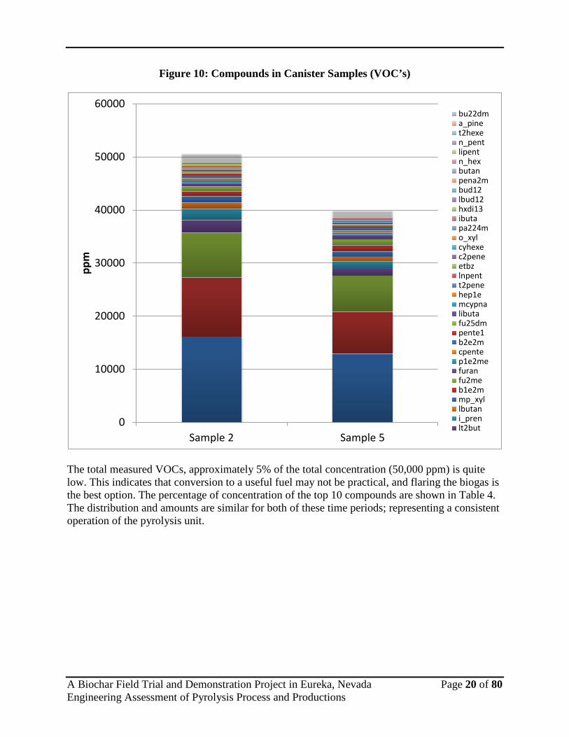
Concentration values for compounds that exceed 10 ppm in the sample are shown in the column graph below, Figure 10. Each canister sample’s compounds are consolidated into each column. The variation in amount of total compounds is not unexpected as gas streams are dynamic and the pyrolysis system was not operating under stable conditions. A canister sample is considered a snap shot over a particular period of time; in this case, only a matter of minutes. As shown, there are many compounds, but the majority consists of 5 major compounds. As shown from the bottom up, these are: ethene (blue), ethane (red), isopropene (green), isopropane (purple), and 1-butene (teal).
MS Data Review Active Chromatogram Plot - 2015-01-07 15:37File: c:\varianws\data\p142_ebc\20141021\2014-10-22 13-18-21 p142m001i002 inj 1 combined ms-fid 050ml.smsSample: P142M001I002 Operator: McDScan Range: 1 - 4612 Time Range: 0.00 - 74.97 min. Date: 2014-10-22 13:18
20 30 40 50 60 minutes
0.0
0.5
1.0
1.5
2.0
2.5
3.0
MCounts 2014-10-22 13-18-21 P142M001I002 Inj 1 combined ms-fid 050ml.SMS TIC35:300
+ ibu
tabu
t1e_is
obu
d13
+ t2b
ut
bud1
2
ipent
+ b1e
2mn_
pent
+ i_p
ren
bu22
dm
+ cpe
nte+ c
penta
pena
3mp1
e2me
n_he
xt2h
exe
+ hxd
i13mc
ypna
pen2
4mbe
nze
+ hex
a2m_
pen2
3m + hep
1e+ n
_hep
t
mecy
hx
pa23
4mtol
ue+ h
ep4m
e
n_oc
t
etbz
mp_x
yl
+ styr
o_xy
l
iprbz
+ a_p
ine
+ bz1
24m_
ibubz
+ bz1
23m
+ detb
z14
n_bu
bz
n_un
de
A Biochar Field Trial and Demonstration Project in Eureka, Nevada Page 20 of 80 Engineering Assessment of Pyrolysis Process and Productions
Figure 10: Compounds in Canister Samples (VOC’s)
The total measured VOCs, approximately 5% of the total concentration (50,000 ppm) is quite low. This indicates that conversion to a useful fuel may not be practical, and flaring the biogas is the best option. The percentage of concentration of the top 10 compounds are shown in Table 4. The distribution and amounts are similar for both of these time periods; representing a consistent operation of the pyrolysis unit.
0
10000
20000
30000
40000
50000
60000
Sample 2 Sample 5
ppm
bu22dma_pinet2hexen_pentlipentn_hexbutanpena2mbud12lbud12hxdi13ibutapa224mo_xylcyhexec2peneetbzlnpentt2penehep1emcypnalibutafu25dmpente1b2e2mcpentep1e2mefuranfu2meb1e2mmp_xyllbutani_prenlt2but

A Biochar Field Trial and Demonstration Project in Eureka, Nevada Page 21 of 80 Engineering Assessment of Pyrolysis Process and Productions
Table 4: VOC Compound Percentage of Canister Samples
Percent of Total Concentration VOC Name Sample 2 VOC Name Sample 5 1 Ethene 1.61% Ethene 1.29% 2 Ethane 1.11% Ethane 0.80% 3 Propene 0.85% Propene 0.68% 4 Propane 0.23% 1-butene 0.14% 5 1-butene 0.22% Propane 0.13% 6 Isobutylene 0.12% Acetylene 0.12% 7 1,3-butadiene 0.11% 1-butene + isobutene 0.11% 8 Acetylene 0.10% 1,3-butadiene 0.10% 9 1-butene + isobutene 0.09% Isobutylene 0.09% 10 1,3 butadiene 0.07% 1,3 butadiene 0.09%
With the vapor removed from the sample, these predominant compounds are in the lower carbon range, which means that the heavier carbon compounds did indeed condense out of the vapor phase into the bio-oil and have not passed through. Figure 11 shows the distribution of compounds based on carbon number from sample number 2.
Figure 11: Biogas Based on Carbon Number
0
5000
10000
15000
20000
25000
30000
2 3 4 5 6 thru 12
ppm
Carbon Number

A Biochar Field Trial and Demonstration Project in Eureka, Nevada Page 22 of 80 Engineering Assessment of Pyrolysis Process and Productions
Lighter hydrocarbons in gas streams are easier to convert into useable fuels and are not as harmful for the environment as heavier hydrocarbons. These results indicate that aside from the liquid passing through the condensers, the compounds that remain are what is expected of a gas stream to be flared or potentially converted into a useful fuel. 5.9 Tenax Cartridge Samples (C11 and up) As with the canister chromatograms, the chromatograms for the tenax cartridges show many compounds. The two figures below, Figure 12 and Figure 13 show sample 2 and sample 5 of the tenax cartridges. These particular cartridges are used to determine what heavy carbon compounds still remain in the gas stream. The compositions of the two tenax samples are similar, but not identical. Figure 14 shows the main VOCs identified in the samples. Clearly, the total amount of compounds are greater in Sample No. 2 then in Sample No. 5.When normalized, the composition of the two samples are more similar. This is shown below in Table 5, which shows the relative amount of the top 10 compounds. All of the compounds are expected to be seen as products of biomass pyrolysis.

A Biochar Field Trial and Demonstration Project in Eureka, Nevada Page 23 of 80 Engineering Assessment of Pyrolysis Process and Productions
Figure 12: GC/MS Chromatogram of Sample 2 Tenax Cartridge
C hrom atogram P lotFile: c :\varianws\data\p142_ebc\tenax\20141029\p142m 002i001.sm sSam ple: p142m 002i001 O perator: M RMScan Range: 1 - 8868 T im e Range: 0.00 - 63.99 m in. Date: 10/29/2014 9:04 PM
10 15 20 25 30 m inutes
0
100
200
300
400
500
600M Counts p142m 002i001.SM S TIC Filtered
50:300
1 Seg 2, SEG M ENT1, Tim e: 9.00-64.00
696 1459 2222 2985 3747 Scans
Tol
uene
+ 1
-Oct
ene
+ c
is-2
-Oct
ene
Eth
ylbe
nzen
em
p_X
ylen
e
+ 1
-Non
ene
+ Is
opro
pylb
enze
ne
n_P
ropy
lben
zene
+ 1
-Met
hyl-3
-Eth
ylbe
nzen
e
+ 1
-Dec
ene
+ s
ec-B
utyl
benz
ene
+ 1
-Met
hyl-4
-Iso
prop
ylbe
nzen
e
+ 1
Me4
nP_n
B_1
3dM
e5E
benz
ene
+ U
ndec
ane
2Mbu
tyl_
1245
tMeb
enze
ne
+ te
rt-1
-But
yl-2
-Met
hylb
enze
ne
+ D
odec
ane
1,3,
5-T
rieth
ylbe
nzen
e
1,2,
4-T
rieth
ylbe
nzen
e
+ N
orfa
rnes
ane
Trid
ecan
e
Far
nesa
ne

A Biochar Field Trial and Demonstration Project in Eureka, Nevada Page 24 of 80 Engineering Assessment of Pyrolysis Process and Productions
Figure 13: GC/MS Chromatogram of Sample 5 Tenax Cartridge
C hrom atogram P lotFile: c :\varianws\data\p142_ebc\tenax\20141029\p142m 002i002.sm sSam ple: p142m 002i002 O perator: M RMScan Range: 1 - 8898 T im e Range: 0.00 - 63.99 m in. Date: 10/29/2014 10:37 PM
10 15 20 25 30 m inutes
0
100
200
300
400
500
M Counts p142m 002i002.SM S TIC Filtered50:300
1 Seg 2, SEG M ENT1, Tim e: 9.00-64.00
696 1459 2222 2985 3747 Scans
Tol
uene
1-O
cten
e+
Oct
ane
cis-
2-O
cten
e
Eth
ylbe
nzen
em
p_X
ylen
e
+ 1
-Non
ene
+ N
onan
e
+ Is
opro
pylb
enze
ne
+ 1
-Met
hyl-3
-Eth
ylbe
nzen
e
+ 1
-Dec
ene
+ 1
-Met
hyl-4
-Iso
prop
ylbe
nzen
e
+ 1
Me4
nP_n
B_1
3dM
e5E
benz
ene
+ U
ndec
ane
+ 2
Mbu
tyl_
1245
tMeb
enze
ne
+ n
-Pen
tylb
enze
ne
+ D
odec
ane
1,3,
5-T
rieth
ylbe
nzen
e
1,2,
4-T
rieth
ylbe
nzen
e
+ N
orfa
rnes
ane
Trid
ecan
e
Far
nesa
ne

A Biochar Field Trial and Demonstration Project in Eureka, Nevada Page 25 of 80 Engineering Assessment of Pyrolysis Process and Productions
Figure 14: Biogas Tenax Cartridge Samples
The number of compounds decreased as the carbon number increased; however, the level is high starting at C6 which indicates that many higher carbon compounds were not condensed out in the bio-oil. Sample 2 and sample 5 are shown in the graph below, Figures 15. Sample 5 contained high carbon number compounds that were not seen in sample 2.
Table 5: Relative Amount of VOCs in Tenax Samples
Relative Amount of VOCs VOC Name Sample 2 VOC Name Sample 5 1 Toluene 40.97% Toluene 12.20% 2 mp_Xylene 17.90% 1-nonene 6.93% 3 Isopropylbenzene 5.52% 1-octene 3.42% 4 1-octene 5.30% Toluene 2.74% 5 Octane 4.72% Ethylbenzene 1.15% 6 1-Methyl-3-Ethylbenzene 4.42% Isopropylbenzene 1.06% 7 1-decene 3.44% 1-Methyl-3-Ethylbenzene 0.60% 8 1-Methyl-4-Ethylbenzene 3.20% 1-Methyl-4-Ethylbenzene 0.33% 9 Ethylbenzene 2.92 Octane 0.29% 10 1-nonene 2.80% 1,3,5-trimethylbenzene 0.29%
0
200000
400000
600000
800000
1000000
1200000
Sample 2 Sample 5
ug/m
3
octad pristheptad hexadpentad tdecfarnes nhxbze124bz e135bzt1bm35bz nptbzt1bm2bz tm_tbbznone2c none3coct2ec oct2ett1be4bz tridecnorfarn dodecnone3t m12e3bzm13e2bz debz12m12e4bz m1np2bznone2t i_bubzs_bubz m1np3bzm14e2bz mb2tmbzm1ipr2bz n_prbzn_unde n_nonm1ipr3bz mpbmebzm1e2bz n_decbz135m o_xylm1e4bz none1etbz m1ipr4bzdec1e m1e3bz

A Biochar Field Trial and Demonstration Project in Eureka, Nevada Page 26 of 80 Engineering Assessment of Pyrolysis Process and Productions
Figure 15: Tenax Cartridge Samples Carbon Numbers
The total amount of gases produced cannot be determined from these samples. Access to the biogas stream to measure the total flow rate was not available during the sampling campaign in Eureka; there was only a port available to remove a sample stream. While equipment to measure the gas flow rate was brought to the demonstration in Cle Elum, Washington, the system did not maintain a proper throughput, which caused all of the flows to vary to the point where the data could not be analyzed. 5.10 Biochar Although the system was not functioning at an optimal state, the rotating kiln was maintaining 500 C to 550 C and passing biomass through at a residence time of approximately 5 to 10 minutes. In Eureka, the feed rate of biomass was dependent on the manual process of sorting the chipped PJ to ensure homogeneity. After one full day of operation, 6 drums, at approximately 200 lbs. per drum were produced. Biochar was also produced during the demonstration in Cle Elum, Washington. This biochar was for use in projects taking place in the State of Washington. The pyrolysis oil was going to be used by WSU and PNNL but it was determined that the oil was not of typical pyrolysis oil quality and therefore it was not received. Furthermore, an energy balance was not achieved due to the process issues mentioned previously in this report.
3495174
74 320
0100000200000300000400000500000600000
7 8 9 10 11 12
ug/m
3
Carbon Number
Sample 2
Sample 5

A Biochar Field Trial and Demonstration Project in Eureka, Nevada Page 27 of 80 Engineering Assessment of Pyrolysis Process and Productions
A full analysis of the biochar as well as the EcoCell growth studies could be achieved with biochar collected from Eureka, Nevada. While this does not provide all of the necessary information to perform an energy balance and life cycle assessment, the quality of the biochar has been investigated. 5.11 Proximate and Ultimate Analysis The proximate and ultimate analysis performed by the Environmental Analysis Facility (EAF) at DRI provided the results shown in Table 6.
Table 6: Proximate and Ultimate Analysis of PJ Biochar and Feedstock
Sample ID Eureka
Biochar Uncertainty Eureka
Feedstock Uncertainty
Moisture Content % 2.91 0.10 4.76 0.33 Volatile Matter (db) % 41.90 1.95 84.84 1.00 Fixed Carbon (db) % 57.42 3.42 14.98 0.45
Ash (db) % 0.68 0.07 0.18 0.08 Nitrogen % 0.48 0.13 0.38 0.06 Carbon % 77.90 0.69 49.18 0.98
Hydrogen % 3.18 0.03 6.12 0.21 Oxygen % 17.94 0.10 40.51 0.69
Energy Content (dry basis) MJ/kg 28.66 19.92 H/C (atomic ratio) 0.49 1.49 O/C (atomic ratio) 0.17 0.62
It is clear from these results that significant carbonization took place in the pyrolysis unit. The energy content of the biomass increased from 19.92 MJ/kg as a raw feedstock to 28.66 MJ/kg as biochar. Similarly, the fixed carbon increased from 14.98% to 57.42%. For comparison to other reported biochar, a short literature review provided a range of results from the same procedures on different types of biochars 5,6,7,8,9,10,11 These results are shown in Table 7.

A Biochar Field Trial and Demonstration Project in Eureka, Nevada Page 28 of 80 Engineering Assessment of Pyrolysis Process and Productions
Table 7: PJ Biochar Result Comparison
Sample ID Eureka
Biochar Literature Min Literature Mx
Moisture Content % 2.91 0.35 3.66 Volatile Matter (db) % 41.90 6.40 85.68 Fixed Carbon (db) % 57.42 2.08 93.60
Ash (db) % 0.68 1.00 18.78 Nitrogen % 0.48 0.19 1.30 Carbon % 77.90 59.19 92.30
Hydrogen % 3.18 0.05 3.80 Oxygen % 17.94 4.05 39.15
H/C (atomic ratio) 0.49 0.04 1.09 O/C (atomic ratio) 0.17 0.04 0.40
The range of biochar characteristics in the literature is quite large. There are many variables affecting the characteristics of biochar; from the type of feedstock to the type of thermal treatment. For all of the chosen comparisons, similar pyrolysis units and operating conditions were chosen. Energy content was only reported in one of the publications and therefore a range was not presented. An important indicator on the performance of biochar is a comparison of the hydrogen to carbon molar ratio and oxygen to carbon ratio. Displayed on a graph, this is known as a Van Krevelen diagram. Europe has set a standard requirement for biochar on the Van Kreveln diagram, as shown in Figure 16.12 In this figure, the Eureka biochar is compared to other biochars found in literature.13 Biochars were chosen for comparison that were treated in the range of 400 C to 500 C using various types of biomass. The type of biomass and temperature at which it was treated are shown in the legend of the graph. The graph shows that the biochar produced in Eureka from PJ has similar characteristics to biochar reported on in literature.

A Biochar Field Trial and Demonstration Project in Eureka, Nevada Page 29 of 80 Engineering Assessment of Pyrolysis Process and Productions
Figure 16: Van Krevelen Diagram of Various Biochars
5.12 FTIR The use of FTIR provides qualitative descriptive information regarding the types of organic functional groups contained within the biochar. Figure 17 shows FTIR spectra of raw PJ and the biochar produced from PJ. The raw PJ spectrum shows very little detail above 1800 cm-1, which can be seen in larger particle sizes under FTIR. The spectrum of the biochar is typical of other examples in the literature. 14,15,16,17,18,19 The broad peak at 3100-3600 cm-1 is associated with O-H bonds in water and alcohols. The peaks at 2800-3000 cm-1 are associated with aliphatic C-H bonds. The strong peak near 1000 cm-1 is due to C-O-C bonds. This is typically the dominant feature seen in carbohydrate sturctures. The other relatively strong peak near 1600 cm-1 can be attributed to multiple functional groups, including aromatic C=C stretching and possibly carbonyl groups (C=O). The enhancement of this peak in the biochar compared to raw PJ suggests that significant charring reactions occurred.

A Biochar Field Trial and Demonstration Project in Eureka, Nevada Page 30 of 80 Engineering Assessment of Pyrolysis Process and Productions
Figure 17: FTIR of Raw PJ and Biochar
5.13 Structure and Morphology (SEM/EDS) Scanning Electron Microscopy (SEM) is important for characterization of biochar by showing whether or not pores have been developed. Pores are indications of a biochar’s ability to retain soil nutrients, improve water holding capacity, and provide space for microbial activity.19 Figure 18 shows an SEM image of biochar from Eureka. The image portrays a surface that is somewhat smooth or defined, as has been reported with other biochars 5,19, and there is clear indication of pore development. It has been reported that higher temperature and longer residence time influences the number and area of pores. 18
50556065707580859095100
5001000150020002500300035004000
% T
rans
mitt
ance
wavelength (cm-1)
Raw PJ
Biochar

A Biochar Field Trial and Demonstration Project in Eureka, Nevada Page 31 of 80 Engineering Assessment of Pyrolysis Process and Productions
Figure 18: SEM Image of Eureka Biochar
Energy-Dispersive Spectroscopy (EDS) of the biochar surface revealed that silicon, calcium, and iron are present on the surface along with carbon and oxygen. The silicon, calcium, and iron can be seen in Figure 19 as the compounds still attached to the fibrous surface. The amount of these compounds, silicon (0.77%), calcium (2.37%), and iron (6.42%) are not unusual.
Figure 19: EDS Image of Eureka Biochar

A Biochar Field Trial and Demonstration Project in Eureka, Nevada Page 32 of 80 Engineering Assessment of Pyrolysis Process and Productions
Further results and discussion on the properties of biochar in regards to their use as a soil amendment will be determined upon completion of the grow studies being conducted in DRI’s EcoCells. However, it is important to note that a complete analysis was accomplished on Amaron Energy’s smaller unit while at a demonstration in Washington. This report can be found in Appendix A. Results from this previous report show that the small-scale unit was effective at generating pyrolysis oil. While the produced biochar demonstrated similar characteristics, the oil yield was a bit higher at 61% and contained less water content (28%) as opposed to the demonstration in Eureka. The oil produced out of this smaller unit maintained the proper characteristics of pyrolysis oil, a by-product with a potential revenue stream to help offset the cost of generating biochar. Gas analysis was also performed during the previous demonstration, but it cannot be assumed that the larger unit would produce the same biogas. 5.14 Biochar Field Studies After a second demonstration (Cle Elum, Washington), Amaron Energy has worked on improving their unit to produce pyrolysis oil with an increased value. These improvements include a higher capacity cooling system on their condensers, and enhanced baffles inside the kiln. The addition of baffles should provide greater rotation of the biomass as it passes through the reactor zone allowing for a more uniform product, and higher throughput. 5.15 Life Cycle Assessment Without the information required to perform an energy balance, a life cycle assessment (LCA) cannot be accurate. However, an LCA on a biochar process with expected values can be performed to identify the feasibility of producing biochar through fast pyrolysis. This is an important analysis as it will help determine the most appropriate method to produce biochar. Most current literature favors fast pyrolysis even though it would appear a higher quality biochar can be produced from slow pyrolysis. Slow pyrolysis, however, can take days to produce where fast pyrolysis is in the order of minutes. The largest benefit from an LCA stems from comparison of different technologies, practices, or applications. For this particular project there will not be a comparison towards competing technologies as it is outside the scope of work. However, the results can be used for comparison in literature or future studies. This LCA was developed with the support of GREET and SimaPro software. 20,21 The LCA developed for this project uses real data points where available, and assumptions about pyrolysis and application where data is not available. Since the source of the PJ and location of pyrolysis is known, all of the energy inputs from harvesting and transporting to the pyrolysis unit have been determined. Since sufficient data was not collected on the pyrolysis unit, a default pyrolysis plant is used. The assumption was put into the model that 50% of the raw biomass would result in bio-oil, 25% in biochar, and 25% in biogas and losses in the system.

A Biochar Field Trial and Demonstration Project in Eureka, Nevada Page 33 of 80 Engineering Assessment of Pyrolysis Process and Productions
Furthermore, the default pyrolysis unit assumes the energy input is natural gas, whereas the Amaron Energy unit is run off of propane and they hope that in the future a large portion of that can be offset by the biogas produced in the process. The analysis can be divided up into four segments: cutting, chipping, transport (to the plant), pyrolysis, and transportation to a farm (10 miles away). Since the current belief is that pyrolysis is driven by the generation of bio-oil, the LCA has been set up that the energy inputs, and emissions generated during the first 4 segments of the LCA are solely responsible to the bio-oil. Only the last segment, transportation to the farm, is dedicated to the biochar. Therefore, as shown in Table 8, 22 MJ/kg bio-oil of life-cycle energy use is required.
Table 8: LCA Based on Pyrolysis Oil
Pyrolysis Oil Fuel Use
(MJ/tonne biomass) Life Cycle Energy Use
(MJ/kg oil) Life Cycle GHG (gCO2e/kg oil)
Cutting (gasoline)
12.7 0.0 0.4
Chipping (diesel)
20.6 0.0 6.5
Transport of Wood Chips (diesel)
2962.4 6.7 49.2
Pyrolysis (natural gas)
877.1 14.8 89.9
Total Life Cycle Burdens
21.6 146.0
Even though the distance of transporting the wood chips to the pyrolysis unit was only 1 mile, the energy use for a heavy-duty diesel truck is a significant portion of the total life cycle energy use. The total life cycle burden of 22 MJ/kg is higher than typical energy content in the produced bio-oil. However, other benefits of the process stem from the removal of PJ from landscapes where it has detrimental effects. Furthermore, the produced bio-oil may be able to offset fossil-based transportation fuels. The production of biochar is only considered to have an impact on transportation to its application. For this model it was assumed that the biochar would only have to be transported 10 miles using a heavy duty diesel truck. This transport results in an energy use of 34 MJ/kg as shown in Table 9.

A Biochar Field Trial and Demonstration Project in Eureka, Nevada Page 34 of 80 Engineering Assessment of Pyrolysis Process and Productions
Table 9: LCA Based on Biochar
Pyrolysis Biochar Fuel Use
(MJ/tonne biochar) Life Cycle Energy Use
(MJ/kg biochar) Life Cycle GHG (gCO2e/kg char)
Transport (diesel)
29.6 33.5 246.1
Table 9 shows the energy use of producing and transporting the biochar to be greater than the energy contained in the biochar itself; however, the use of biochar is to provide benefits other than energy content. Results from Task 2 of the project, the grow studies in the EcoCell’s will demonstrate the benefits that exist from biochar when used as a soil amendment. 5.16 Discussion The use of the Amaron Pyrolysis unit proved to be sufficient in the production of biochar. A yield of approximately 25 percent biochar is well within the expected range. It is understood that this was the first demonstration of their large-scale reactor and therefore yields may be further improved. The majority of yield from the reactor is pyrolysis oil; which has the potential to be a revenue generating by-product. However, during this demonstration, the oil was not of sufficient quality to be accepted in the market. Improvements could be made to the reactor that would increase the quality of the pyrolysis oil; such as increased temperature control on the condensers. In general, a revenue generating oil is necessary in order to economically produce biochar through pyrolysis. Chemical analysis of the biochar showed that the generated biochar is consistent with the standards and specifications for biochar around the world. Figure 16 provides insight into the quality of the generated biochar. Greater control of operating conditions in the reactor would further enhance the biochar as well as the oil. The second task in this project provides empirical data on the effectiveness of the generated biochar in different soils and plant types. The use of biochar in the soil is thought to provide environmental benefits which may help offset production costs. Therefore, a basic life-cycle assessment was performed on the Amaron pyrolysis unit. Overall, the energy content in the biochar was less than the energy required to produce the biochar. However, viewing results in this fashion does not account for the many other benefits that biochar may have to offer. The life-cycle analysis provides greater insight into which steps of the process consume the most energy and could be improved. In this case, transporting the biomass, pyrolysis, and transport of the biochar all have large effects. The effect of pyrolysis can be reduced through enhancing the efficiency of the reactor and utilizing waste heat recovery. Transportation of both the biomass and the biochar are two areas that will vary for different situations. The Amaron unit is designed to be portable and therefore could drive down the environmental burdens compared to stationary units. Lastly, the biomass particle size proved to be a crucial element to the process. While in Eureka, Nevada, the unit had several failures due to large particles entering the reactor. The mechanical

A Biochar Field Trial and Demonstration Project in Eureka, Nevada Page 35 of 80 Engineering Assessment of Pyrolysis Process and Productions
components of the feed system require a uniform particle size; a uniformity that is not obtainable through “standard” chipping processes. In order for biomass to function as a fuel in the Amaron pyrolysis unit, further particle sizing and sorting is necessary. An example of the effort required is shown in Appendix B.

A Biochar Field Trial and Demonstration Project in Eureka, Nevada Page 36 of 80 Engineering Assessment of Pyrolysis Process and Productions
References 1 Method and Apparatus for Fast Pyrolysis of Biomass in Rotary Kilns. Coates, Et Al, assignee.
Patent US2012/0063965 A1. 15 Mar. 2012. Print. 2 Mohan, Dinesh., Pittman, C.U., Steele, P.H., “Pyrolysis of Wood/Biomass for Bio-oil: A
Critical Review.” Energy & Fuels 20 (2006): 848-889. 3 Brown,R.C., Thermochemical Processing of Biomass. Wiltshire: Wiley & Sons. 2011. 4 Ozyurtkan, M.H., Ozcimen, D., Mericboyu, A.E., “Investigation of the carbonization behavior
of hybrid poplar.” Fuel Processing Technology 89 9 (2008): 858-863. 5 Yin, R., Lui, R., Mei, Y., Fei, W., Sun, X. “Characterization of bio-oil and bio-char obtained
from sweet sorghum bagasse fast pyrolysis with fractional condensers.” Fuel 112 (2013): 96-104.
6 Bucheli, T.D., Bachmann, H.J., Blum, F., Burge, D., Giger, R., Hilber, I., Keita, J., Leifeld, J.,
Schmidt, H.P. “On the heterogeneity of biochar and consequences for its representative sampling.” Journal of Analytical and Applied Pyrolysis 107 (2014): 25-30.
7 Ramola, S., Mishra, T., Rana, G., Srivastava, R.K. “Characterization and pollutant removal
efficiency of biochar derived from bagasse, bamboo and tyre.” Environ Monit Assess 186 (2014): 9023-9039.
8 Ahmad, M., Lee, S.S., Dou, X., Mohan, D., Sung, J.K., Yang, J.E., Ok, Y.S. “Effects of
pyrolysis temperature on soybean stover- and peanut shell-derived biochar properties and TCE adsorption in water.” Bioresource Technology 118 (2012): 536-544.
9 Ronsse, F., Hecke, S., Dickinson, D., Prins, W. “Production and characterization of slow
pyrolysis biochar: influence of feedstock type and pyrolysis conditions.” GCB Bioenergy 5 (2013): 104-115.
10 Naisse, C., Alexis, M., Plante, A., Wiedner, K., Glaser, B., Pozzi, A., Carcaillet, C., Criscuoli,
I., Rumpel, C. “Can biochar and hydrochar stability be assessed with chemical methods?” Organic Geochemistry 60 (2013): 40-44.
11 Huff, M., Kumar, S., Lee, J.W. “Comparative analysis of pinewood, peanut shell, and
bamboo biomass derived biochars produced via hydrothermal conversion and pyrolysis.” Journal of Environmental Management 146 (2014): 303-308.
12 Goa, X., Yani, S., Wu, H. “Pyrolysis of Spent Biomass from Mallee Leaf Steam Distillation:
Biochar Properties and Recycling of Inherent Inorganic Nutrients.” Energy & Fuels 28 (2014): 4642-4649.

A Biochar Field Trial and Demonstration Project in Eureka, Nevada Page 37 of 80 Engineering Assessment of Pyrolysis Process and Productions
13 Lehmann, J., Joseph, S. Biochar for Environmental Management. Sterling, Va. Earthscan. 2009.
14 Chang,S., Zhao,Z., Zheng, A., He, F., Huang, Z., Li, H. “Characterization of Products from
Torrecfaction of Sprucewood and Bagasse in an Auger Reactor”. Energy & Fuels 26 (2012): 7009-7017.
15 Jamari, S.S., Howse, J.R. “The effect of the hydrothermal carbonization process on palm oil
empty fruit bunch.” Biomass and Energy 47 (2012): 82-90. 16 Eibisch, N., Helfrich, M., Don, A., Mikutta, R., Kruse, A., Ellerbrock, R., Flessa, H.
“Properties and Degradability of Hydrothermal Carbonization Products.” Journal of Environmental Quality 42 (2013): 1565-1573.
17 Reza, M.T., Uddin, M.H., Lynam, J.G., Hoekman, S.K., Coronella, C.J. “Hydrothermal
Carbonization of loblolly pine: reaction chemistry and water balance.” Biomass Conversion and Biorefinery 4 (2014): 311-321.
18 Shaaban, A., Se, S.M., Dimin, M.F., Juoi, J.M., Husin, M.H.M., Mitan, N.M.M. “Influence of
heating temperature and holding time on biochar derived from rubber wood sawdust via slow pyrolysis.” Journal of Analytical and Applied Pyrolysis 107 (2014): 31-39.
19 Ghani, W.A.W.A.K., Mohd,A., Silva, G., Bachmann, R.T., Taufiq-Yap, Y.H., Rashid, U., Al-
Muhtaseb, A.H. “Biochar production from waste rubber-wood-sawdust and its potential use in C sequestration: Chemical and Physical characterization.” Industrial Crops and Products 44 (2013): 18-24.
20 The Greenhouse Gases, Regulated Emissions, and Energy Use in Transportation Model
(GREET), Argonne National Laboratory: 2014. 21 SimaPro LCA Software, PRé Consultants: 2014.

A Biochar Field Trial and Demonstration Project in Eureka, Nevada Page 38 of 80 Engineering Assessment of Pyrolysis Process and Productions
Appendix A: Amaron Small Scale Report

A Biochar Field Trial and Demonstration Project in Eureka, Nevada Page 39 of 80 Engineering Assessment of Pyrolysis Process and Productions
Amaron Energy Mobile Pyrolysis Demonstration Test Results
May 7 – May 8, 2014
Bingen, Washington
Summary
The Washington State Department of Natural Resources (DNR) coordinated a mobile pyrolysis demonstration on May 7th to May 8th, 2014 at SDS Lumber in Bingen, Washington. Two Utah companies, Western Renewable Technologies and Amaron Energy, participated in the demonstration. The demonstration involved converting Douglas-fir planer shavings from the SDS Lumber sawmill into oil, char and syngas using pyrolysis.
Planer shavings Char Oil Photo: Waled Suliman, WSU

A Biochar Field Trial and Demonstration Project in Eureka, Nevada Page 40 of 80 Engineering Assessment of Pyrolysis Process and Productions
Planer Shavings. Photo: Jon Cole, SDS Lumber The purposes and intents behind this project were to demonstrate woody biomass mobile pyrolysis technologies in Washington to: support technologies ready to move from research and development to commercialization; educate Washington residents about the potential for wood energy as a local, renewable energy source to provide jobs in rural communities; create markets for woody biomass from overstocked eastern Washington forests in need of thinning; and develop baseline air emissions data and characterize bio-oil and bio-char produced during the demonstration. As of spring 2014, there are no commercial scale wood pyrolysis units operating in the western United States. Conrad Industries in Chehalis, WA has operated a tire pyrolysis unit since the mid 1980’s.
The two pyrolysis units ran for eight hours each day converting wood planer shavings into oil, char and syngas. Graduate students and professors from Washington State University and the University Idaho sampled the pyrolysis units to determine air emissions, char quality, oil quality and energy efficiency. 165 people attended the two-day demonstration and a survey was administered to attendees to gauge their knowledge and support of pyrolysis and wood energy efforts.
The mobile pyrolysis demonstration was funded by the USDA Forest Service in partnership with the WA State Department of Natural Resources, WA State Department of Commerce, Washington State University Energy Program, Oregon Department of Forestry and the Oregon Department of Energy. Funds were provided by the USDA Forest Service Forest Biomass Market Development and Supply Assessment grant 2010-DG-11062765-021.

A Biochar Field Trial and Demonstration Project in Eureka, Nevada Page 41 of 80 Engineering Assessment of Pyrolysis Process and Productions
Amaron Energy pyrolysis unit and demonstration attendees. Photo: Chuck Hersey, WA DNR

A Biochar Field Trial and Demonstration Project in Eureka, Nevada Page 42 of 80 Engineering Assessment of Pyrolysis Process and Productions
Evaluation of Amaron Energy Mobile Pyrolysis Unit Dr. Manuel Garcia-Perez and a team of 10 graduate students collected samples from the pyrolysis units during the mobile pyrolysis demonstration to measure: oil yield, oil quality, char quality and energy efficiency. Feedstock for both pyrolysis units consisted of Douglas-fir planner shavings from the SDS Lumber sawmill with a moisture content of 8.6%. Dr. Garcia-Perez is an associate professor in the Department of Biological Systems Engineering at Washington State University working on fundamental studies to understand cellulose and lignin pyrolysis mechanisms and the development of selective pyrolysis reactors and bio-refinery concepts to convert bio-oils into bio-fuels and bio-chemicals. Here is a summary of the Amaron Energy pyrolysis evaluation results written by Dr. Manuel Garcia-Perez: Description of technologies used:
Amaron Energy: Amaron Energy, Inc. (Salt Lake City, UT) provided the use of their rotary kiln reactor heated by pyrolysis gas supplemented with propane. The biomass enters through a feeder into a N2 purge/air-lock chamber at a feed rate of 12.2 kg/hr. After that it enters a 1.22 m long, 15.25 cm diameter pipe rotating at 12 RPM with a 1.0o slope to guide the particles down through the reactor. Gases were conveyed with a 0.14 m3/hr nitrogen carrier gas. Three burners heated the walls of the reactor to 450 +/- 5 oC. The average particle residence time in the reactor was 10 minutes. The char exited the reactor into a collection pot while the vapors entered a spray condenser (condenser 1) which was started with diesel and also utilized recirculated oil for spraying. The diesel is non-soluble with the oil and separates easily. The re-circulated oil was cooled with a set of radiators to approximately 82 oC. Gases and vapors leaving the spray condenser entered a spray cyclone (condenser 2) held at 32 oC. Gases leaving the cyclone entered an electrostatic precipitator (15 mA) followed by a fibrous char filter. A vacuum pump pulled a 1 inch (H2O, gauge) vacuum. These gases were sent back to the pyrolysis reactor burners to provide approximately 1/3 of the required heat.
Table 1 summarizes some of the main characteristics of the technology used by Amaron Energy.

A Biochar Field Trial and Demonstration Project in Eureka, Nevada Page 43 of 80 Engineering Assessment of Pyrolysis Process and Productions
Table 1.- Summary of operational conditions used during both runs
Description Amaron Energy
Reactor type Rotary kiln
Wood feed rate 12.2 kg/hr
Heating mechanism Gas burner
Particle residence time in reactor 10 minutes
Reactor wall temperature 450 oC
Carrier gas, vacuum pulled 0.14 m3/hr N2, 1 inch (H2O)
Condenser system (1) Spray condenser, (2) Spray cyclone
Comments: Both reactors used material with a moisture content of 8.6 wt. %. The material was sieved and the fraction with particle size larger than 5 mm was pyrolyzed.
1. Percent Oil (30 points maximum)
Criteria used in the evaluation: Percent of dry feedstock that is converted into bio-oil.
>60%: 30 points
50% to 60%: 20 points
40% to 50%: 15 points
30% to 40%: 10 points
< 30%: 0 points
Results: The data collected and the yield of products obtained from Amaron Energy is shown in Table 2. The processed biomass had a moisture content of 8.6 wt. %. This concentration was used to correct the data collected to express the yield on dry biomass basis.

A Biochar Field Trial and Demonstration Project in Eureka, Nevada Page 44 of 80 Engineering Assessment of Pyrolysis Process and Productions
Table 2.- Data used to calculate the yield of products of Amaron Energy
Items for Mass Balance Value Yield (%, dry biomass basis)
Bio-oil added into condenser 1 (kg) 8.80
Biooil added into condenser 2 (kg) 3.56
Feedstock processed during test (kg) 24.01
Moisture content (wt. %) 8.6
Water in feedstock (kg) 2.06
Dried Feedstock (kg) 21.94 100
Total run (hours) 2
Average feeding rate (kg/h) 12.01
Bio-char production (kg) 5.38
Bio-char estimated in filter (kg) 0.16
Bio-char Yield (%) 25.23
Bio-oil production in Condenser 1 (kg) 19.32
Bio-oil production in condenser 1 (Samples for analysis (kg))
1.97
Total bio-oil condenser 1 – initial biooil in condenser 1 (kg)
12.49
Bio-oil production Condenser 2 (kg) 5.49
Bio-oil production in condenser 1 (Samples for analysis) (kg)
0.92
Total bio-oil in condenser 2 (kg) 6.41
Total bio-oil in condenser 2 – initial biooil in condenser 2 (kg)
2.85

A Biochar Field Trial and Demonstration Project in Eureka, Nevada Page 45 of 80 Engineering Assessment of Pyrolysis Process and Productions
Bio-oil production in Electrostatic precipitation (ESP) (kg)
0.16
Water in the bio-oil from feedstock moisture (kg) 2.06
Bio-oil produced from the dry feedstock (kg) 13.44
Yield of bio-oil (%) 61.26
Yield of Gases (by difference) (%) 13.51
Because the overall bio-oil yield (on dry basis) is over 60 % we recommend that Amaron receive the full 30 points given for this evaluation criterion.
Comments: The higher bio-oil yield obtained by Amaron is mainly due to the processing temperature being closer to the optimal recommended value for maximizing bio-oil yields. Furthermore, the use of a carrier gas and lower temperatures by Amaron minimized the secondary reactions in vapor phase and consequently resulted in higher bio-oil yields. The overall yield of oil obtained is slightly lower than the one reported for other fast pyrolysis reactors (60-70 %) (Liaw et al. 2012, Wang et al. 2005, Garcia-Perez et al. 2008).
References:
Liaw S-S, Wang Z, Ndegwa P, Frear C, Ha S, Li C-Z, Garcia-Perez M: Effect of pyrolysis temperature on the yield and properties of bio-oils obtained from the auger pyrolysis of Douglas Fir wood. Journal of Analytical and Applied Pyrolysis 93 (2012) 52-62.
Wang X, Kersten SRA, Prins W, van Swaaij WPM: Biomass Pyrolysis in a Fluidized Bed Reactor. Part 2: Esperimental Validation of Model Results. Ind. Eng. Chem Res. 2005, 44, 8786-8795
Garcia-Perez M, Wang X-S, Shen J, Rhodes MJ, Tian F, Lee W-J, Wu H, Li C-Z: Fast Pyrolysis of Oil Malee Woody Biomass; effect of Temperature on the Yield and Quality of Pyrolysis Products. Ind. Eng. Chem. Res. 2008, 47, 1846-1854
2. Oil Quality Analysis (10 points maximum)
Criteria used in the evaluation:
A Moisture content (measured by K-F titration) (Maximum 5 points)

A Biochar Field Trial and Demonstration Project in Eureka, Nevada Page 46 of 80 Engineering Assessment of Pyrolysis Process and Productions
between 0 and 15 wt. % : 5 points
between 15 and 20 wt. % : 3 points
between 20 and 30 wt. %: 2 points
more than 30 wt. %: 0 points
B.- Homogeneity of the liquid produced (pictures of oils in separation funnels and microscopic pictures) (Maximum 5 points)
homogeneous liquid (no phase separation): 5 points
heterogeneous liquid (more than one phase): 0 points
Results: The oil produced by Amaron Energy was not homogeneous. Consequently the determination of moisture content was done after separating the phases formed. Table 3 summarizes the results obtained. In the case of Amaron Energy the oil collected in the first condenser was mostly formed by a single phase. The oil collected by Amaron in the second condenser is split between two phases. The data presented in Tables 2 was used to determine the yield of water and the yield of organics produced.
Table 3.- Data to estimate the yield of reaction water produced by Amaron technology Data used in the calculation Value
Oil Collected in First Condenser (kg) 12.49
Water content of Oil collected in First condenser (wt. %) 32.67
Water collected in first condenser (kg) 4.08
Organics collected in first condenser (kg) 8.41
Oil Collected in Second Condenser (kg) 2.85
Estimation of Upper layer (wt. %) 8
Estimated mass in Upper layer in second condenser (kg) 0.23
Water content of oil in upper layer (wt. %) 0.56
Water collected in upper phase of second condenser (kg) 0.001
Organics collected in upper phase of second condenser (kg) 0.229
Estimation of Bottom layer (wt. %) 92

A Biochar Field Trial and Demonstration Project in Eureka, Nevada Page 47 of 80 Engineering Assessment of Pyrolysis Process and Productions
Estimated mass in bottom layer (kg) 2.62
Water content of oil in bottom layer (wt. %) 58.92
Water collected in the bottom layer of second condenser (kg) 1.54
Organics collected in the bottom layer of second condenser (kg) 1.08
Oil collected in the Electrostatic Precipitator (kg) 0.16
Water content of oil Collected in electrostatic precipitator (wt. %) 53.19
Water collected in the Electrostatic Precipitator (kg) 0.08
Organics Collected in the electrostatic Precipitator (kg) 0.08
Overall Water Collected (kg) 5.70
Water from the feedstock (see Table 1) (kg) 2.06
Water produced by the pyrolysis reaction (kg) 3.64
Overall Organics Collected (kg) 9.80
Total Oil Produced from dry feedstock (kg) 13.44
Water content of the whole oil if a dry feedstock were used and the oil was collected in a single completely mixed condenser (mass %)
27.08
Yield of Reaction Water (wt. %) 16.59
Yield of Organics (wt. %) 44.67
Comments: The yield of water in the oil produced by Amaron Energy was close to 17 % with an organics yield of 44.67 %. These yields can be considered good when taking into account the large particles used. The yield of water in fast pyrolysis systems is typically around 10 % (Liaw et al 2012, Wang et al 2005, Garcia-Perez 2008). The yield of organics is typically slightly higher, close to 50 %. The higher yield of water produced is due to the slower heating rate and the retention of sugar oligomers that dehydrate to form additional water. In order to increase the heating rate inside the reactor perhaps it will be interesting to consider adding internal heat transfer surfaces (like moving chains). The slightly lower yield of organics is due to the retention and secondary reactions of lignin oligomers inside the biomass particles.

A Biochar Field Trial and Demonstration Project in Eureka, Nevada Page 48 of 80 Engineering Assessment of Pyrolysis Process and Productions
Evaluation: Because the theoretical water content obtained in the oil produced by this technology (if feedstock is dried and all the oil is collected together) is 27.08 % my recommendation is to grade this item with 2 points. If collected in a single step condensation system phase separation is likely to occur. However, the designers used a two-step condensation system that resulted in relatively stable phases. My recommendation is to grade the homogeneity of their products with 3 points.
References:
Liaw S-S, Wang Z, Ndegwa P, Frear C, Ha S, Li C-Z, Garcia-Perez M: Effect of pyrolysis temperature on the yield and properties of bio-oils obtained from the auger pyrolysis of Douglas Fir wood. Journal of Analytical and Applied Pyrolysis 93 (2012) 52-62.
Hoekstra E, Westerhof RJM, Brilman W, Van Swaaij WPM, Kersten SRA, Hogendoorn KJA, Windt M: Heterogeneous and homogeneous reactions of pyrolysis vapors from pine wood. AIChE Journal. Volume 58, Issue 9, pages 2830-2842, September 2012
Other analyses were conducted but will not be used for grading purposes:
Elemental analysis (CHNS-O)
Table 4.- Elemental Composition of oils produced Amaron Energy
Condenser 1 Amaron Energy Condenser 2 (Aqueous phase)
C (wt. %) 33.48 18.48
H (wt. %) 7.48 8.44
N (wt. %) 0.121 0.11
O (wt. %)* 58.92 72.96
3. Char Quality Analysis (15 points maximum)
Bio-char characterization:
A: Ash content (Maximum 5 points)
between 0 and 10 wt. %: 5 points

A Biochar Field Trial and Demonstration Project in Eureka, Nevada Page 49 of 80 Engineering Assessment of Pyrolysis Process and Productions
between 10 and 15 wt. %: 4 points
between 15 and 20 wt. %: 3 points
between 20 and 25 wt. %: 2 points
more than 25 wt. %: 0 points
Table 5.- Proximate Analysis of the bio-chars produced Amaron Energy
Volatile matter (wt. %) 24.47
Fixed Carbon (wt. %) 74.74
Ash (wt. %) 0.78
Comments: My recommendation is that Amaron Energy receive the maximum evaluation (5 points).
B: Surface area (Maximum 5 points)
more than 300 m2/g: 5 points
between 200 and 300 m2/g: 4 points
between 100 and 200 m2/g: 3 points
between 50 and 100 m2/g: 2 points
bess than 50 m2/g: 0 points
Comments: The chars from Amaron Energy had a very low surface area (less than 1 m2/g). Points: 0.
C: Odors and presence of leachable materials (in water and acetone) (Maximum 5 points)
bio-chars without odor and no soluble material: 5 points
bio-chars with odors and leachable materials: 0 points
Comments: The bio-chars produced by Amaron Energy have pungent odors indicative of bio-oil condensation on the surface. Amaron Energy char is much more pungent before 20 minutes of exposure. This is because the Amaron Energy system utilized a sealed collection pot that did not allow for degassing. Both chars were extracted with acetone in a Soxhlet extractor. The content

A Biochar Field Trial and Demonstration Project in Eureka, Nevada Page 50 of 80 Engineering Assessment of Pyrolysis Process and Productions
of extractable materials in the Amaron Energy chars was 0.95 wt. %. Amaron Energy should make modifications such as a sweep gas to avoid extended bio-char/vapor contact during the cooling period.
Based on the extractable matter of approximately 1% for the chars and the moderate odor after air exposure we recommend a rating of 3 for the chars for Amaron Energy based on the criteria listed.
Other analyses conducted, but not be used for grading purposes:
Elemental composition (CHNS-O)
Table 6.- Elemental Analysis of the Bio-char Produced Amaron Energy
C (wt. %) 75.37
H (wt. %) 3.41
N (wt. %) 0.27
O (wt. %)* 20.17
Ash (wt. %) 0.782
*by Difference
Energy Efficiency Amaron Energy: The Amaron Energy system used propane to heat the reactor. Our measurements of the weight of the propane tank used indicate that 6.6 kg of propane were used in two hours. At the time of the testing the average feeding rate of the biomass was 12.01 kg/h (moisture content 8.6 wt. %) (10.97 kg/h of dry biomass). The heating value of dry lignocellulosic materials is typically 21 MJ/kg because our material contains 8.6 wt. %; the high heating value of the biomass processed is approximately 19 MJ/kg. The technology resulted in the production of 25.23 wt. % of char (typically with a heating value close to 36 MJ/kg) and 44 wt. % of organics (with a heating value typically close to 20 MJ/kg). The high heating value of propane is 50.23 MJ/kg. Energy input will be: 12.01*2 * 19 + 6.6*50.23 = 787.90 MJ Energy output: 0.2523* 21.94 *36 + 0.44* 21.94 * 20 = 392.34 MJ

A Biochar Field Trial and Demonstration Project in Eureka, Nevada Page 51 of 80 Engineering Assessment of Pyrolysis Process and Productions
The efficiency of the process is approximately: 49.79 %. The efficiency of the process can be improved if the heat in the combustion gases produced is recovered (for example to heat the air). The main issue is not the relatively low thermal efficiency but the use of a high quality fuel to produce a low quality energy carrier (like bio-oil and bio-char). This efficiency could be tolerated if the energy quality is improved. In order to improve this problem the system should be heated with a low quality fuel (example biomass fraction sieved) and several units should be added to recover the heat contained in the combustion gases. Amaron Energy should work hard on heat integration to improve their systems for commercialization. Table 7: Summary of Mobile Pyrolysis Unit Evaluation Criteria Results and Scoring Amaron Energy
Criteria Amaron Score Oil Yield (%) 61.26% 30 Oil Moisture (%) 27.08% 2 Oil Homogeneity 3 Char Ash Content 0.78% 5 Char Surface Area less than 1 m²/g 0 Char Odor 3 Air Emissions 24 Technical Maturity 15 Energy Efficiency 49.79% Not scored Total Score 82
Note: An evaluation committee was formed to review the mobile pyrolysis test results and select a vendor for another pyrolysis demonstration in the fall 2014. The evaluation committee participated in a conference call on July 8, 2014 to review and discuss the pyrolysis test results from Amaron Energy and Western Renewable Technologies. The committee accepted the scores recommended by Dr. Garcia-Perez for oil yield, oil moisture, oil homogeneity, char ash content, char surface, and char odor. The committee accepted the scores recommended by Dr. Tom Jobson for air emissions. The committee discussed the technical maturity score for each vendor and assigned a score of 15 to Amaron Energy and 10 to Western Renewable Technologies. Evaluation Committee: Dr. Manuel Garcia-Perez, Washington State University; Dr. Tom Jobson, Washington State University; Ron Saranich, USDA Forest Service, David Sjoding, Washington State University Energy Program; Dr. Armando McDonald, University of Idaho; Dr. Mark Coleman, University of Idaho; Peter Moulton, Washington State Department of Commerce and Chuck Hersey, Washington State Department of Natural Resources.

A Biochar Field Trial and Demonstration Project in Eureka, Nevada Page 52 of 80 Engineering Assessment of Pyrolysis Process and Productions
Air Emissions
An air quality permit is the main environmental permit required to operate a pyrolysis unit in Washington State. DNR obtained an air quality permit for the mobile pyrolysis demonstration from the Washington State Department of Ecology Central Regional Office as they are the local air quality authority for Klickitat County. DNR also complied with the State Environmental Policy Act for the mobile pyrolysis demonstration.
Tom Jobson, an associate professor in the Department of Civil & Environmental Engineering, Laboratory for Atmospheric Research at Washington State University, sampled air emissions from the two pyrolysis units during the demonstration. Pollutants measured were carbon monoxide (CO), carbon dioxide (CO2), nitrogen oxide (NO), total nitrogen oxides (NOx), and PM2.5 mass concentration.
Here is a summary of the air emissions testing of the two pyrolysis units written by Tom Jobson:
1.0 Scope
WSU measured pollutant concentrations in the vent stacks of portable wood chip pyrolysis units during a demonstration of these units at Bingen, WA during May 6 to May 7, 2014. Two units were tested: a unit built and operated by Amaron Energy, and a unit operated by Western Renewable Technologies (WRT). Gases and particle were continuously measured from the vent stack on these units. Pollutants measured were carbon monoxide (CO), carbon dioxide (CO2), nitrogen oxide (NO), total nitrogen oxides (NOx), and PM2.5 mass concentration. Flow rates from the stacks were not measured.
The purpose of the pollutant sampling was to provide a score that rated the emission from each of the units. The scoring system is given in Table 1. High scores reflect good outcomes.
Table 1. Pollutant Scoring Pollutant Allocated Score PM2.5 concentration (µg/m3) 10 NOx (ppmv) 5 CO (ppmv) 5 CO2 (ppmv) 5
* ppmv = parts per million by volume
1.1 Measurement Methodology
Table 2 lists the equipment used to measure the pollutants. These instruments are listed as federal reference methods for the measurements of these pollutants.
Table 2. Measurement Instrumentation

A Biochar Field Trial and Demonstration Project in Eureka, Nevada Page 53 of 80 Engineering Assessment of Pyrolysis Process and Productions
Pollutant Instrument DL Time resolution CO TECO 48 50 ppbv 30 s NO & NOx TECO 42 0.25 ppbv 30 s CO2 LiCor 840 5 ppmv 1 s PM2.5 TSI DustTrack 8520 0.001 mg/m3 1 s
The CO and NOx analyzers were calibrated before the test using gravimetrically certified standards for CO (500 ppmv ± 1%) and NO (1 ppmv ± 1%) purchased from Scott Marrin Inc. The CO2 and PM2.5 instrument were factory calibrated. The PM2.5 instrument detects particles by optical scattering and is sensitive to particles between the size range 0.1 to 10 μm. Data from the instruments was recorded and displayed on a laptop computer at 1 second intervals using a LabJack U3 A/D hardware device (LabJack) and DaqFactory software (Azeotech). The instruments were rack mounted in an instrument case and housed in a cargo van that was located next to the pyrolysis unit. Power to the instruments was supplied by a small Honda portable generator that was set approximately 50 feet away from the unit. A photograph showing the instruments and laptop in the cargo van onsite at Bingen, WA is shown in Figure 1.
Figure 1. Photograph of instrumentation and laptop recording data from pyrolysis emissions testing in Bingen, WA.
1.2 Stack Vent Sampling
To conduct the air sampling from the stack vents a custom sheet metal collar was secured to the vent by a hose clamp. The collar extended approximately 20 inches above the stack and had 2

A Biochar Field Trial and Demonstration Project in Eureka, Nevada Page 54 of 80 Engineering Assessment of Pyrolysis Process and Productions
ports that allowed for insertion of air sampling lines for the gas and PM2.5 instruments. A photograph of the collar attached to the Amaron Energy and Western Renewable Technologies stack vents are shown in Figures 2 and 3 respectively. The Amaron stack vent gas flow was very low but very hot (~ 430 °C) and concentrated. Gas sampling for the Amaron stack required the use of an ejector diluter that allowed a small known sample flow to be pulled from the stack vent and diluted with a known flow of dry zero air. This cooled the flow, reduced the water content, and brought pollutant concentrations in range for measurements by the continuous analyzers Sampling from the stack was done through ~8 feet of 1/8” stainless steel tubing attached to the inlet of the ejector diluter. The zero air flow (13 SLPM) into the ejector diluter creates a low pressure zone that pulls air through the 1/8” sample line. Zero air flow was controlled by a rotameter and the flow continuously measured by an in-line flow meter (TSI XX) and recorded. The exit side of the diluter containing the sample flowed through ½” PFA tubing back to the instruments in the cargo van. The sample line was connected to a manifold on the instrument rack from which each of the gas analyzers subsampled. The sample flow and zero air flow were measured onsite using a primary gas flow measuring device (Bios DriCal). The Amaron stack vent gas sample flow was diluted by a factor of 90. The PM2.5 mass concentrations were low and therefore no dilution was necessary. A ¼” copper sample line was use to connect the PM2.5 instrument to the sample collar on the stack vent. The end of the sample tubing was located to sample from the center of the stack inside the collar. Figure 4 shows a schematic of the gas sampling from the Amaron stack vent.

A Biochar Field Trial and Demonstration Project in Eureka, Nevada Page 55 of 80 Engineering Assessment of Pyrolysis Process and Productions
Figure 2. Photograph of emissions sampling collar and sampling lines (1/8” stainless steel for gas sampling, ¼” copper for particle sampling) on the Amaron vent.
Figure 3. Photograph of emissions sampling collar and sampling lines on Western Technologies stack vent.In contrast to Amaron sampling, direct gas sampling from the WRT stack was done without dilution to measure CO, NOx, and PM2.5. Stack dilution was necessary to bring CO2 mixing ratios within range of the sensor. Flow from this WRT vent was much larger, and cooler, owing to the use of a blower to feed air into the syn gas post combustor.
Figure 4. Schematic of gas and PM sampling from the Amaron roof top stack vent. An ejector diluter (ED) was used to pull air from the stack vent and dilute it by a factor of 90 with dry zero air from a compressed gas cylinder. Diluted vent gas was sampled by gas phase instrumentation. PM2.5 was sampled directly from the stack without dilution.

A Biochar Field Trial and Demonstration Project in Eureka, Nevada Page 56 of 80 Engineering Assessment of Pyrolysis Process and Productions
2.0 Data
A time series of pollutant levels measured in the Amaron stack vent is shown in Figure 5. Data was summarized as a 1 hour average concentration, calculated from the data between 11 am and 12 noon. CO was much more variable than other pollutants. We noticed high CO mixing ratios when the Amaron team periodically cleared out a bio char blockage. The 1 hour averages and standard deviations are shown in Table 4.
Syn gas samples were also collected and analyzed but did not factor into the scoring. The syn gas was analyzed by University of Idaho. Syn gas was collected into SUMMA electropolished canisters supplied by WSU. The canisters were filled buy the vendors on site. This consisted of attaching an evacuated 6-L canister to Tygon tubing used by the vendors for syn gas sampling. The canisters filled to approximately 3 psig. Two canisters were collected from each vendor, one immediately after the other. Gaseous products were taken from the canister by a syringe (0.5 mL) were analyzed by gas chromatography-thermal conductivity detector (GC-TCD, GOWMAC, Series 350) equipped with a HaySep DB stainless steel packed column (9.1 m × 3 mm) at 30oC. Standard curve was prepared from individual gas (i.e. N2, CO, CO2, CH4) for quantification. Results are presented in Table 3 and Figure 6 shows an example chromatogram.

A Biochar Field Trial and Demonstration Project in Eureka, Nevada Page 57 of 80 Engineering Assessment of Pyrolysis Process and Productions
Figure 5. Amaron stack vent emissions showing PM2.5 concentration, NOx (black trace) and NO (red trace), CO2 mixing ratio, and CO. Dashed vertical line indicates when ambient air sampling occurred to illustrate difference in pollutant concentrations between the stack and ambient air.
Table 3. Percent abundance of major components measured in syn gas samples
Compound Amaron 1 (%)
Amaron 2 (%)
N2 + O2 39.9 36.1 CO 33.2 40.4 CH4 3.8 3.3 CO2 23.4 19.8
Figure 6. Chromatogram of Amaron syn gas showing major components indicated in Table 3.
3.0 Discussion
Average abundance of pollutants measured in the Amaron Energy vent stack are given in Tables 4 along with scores. The Amaron unit heated wood chips using propane combustion. The syn gas produced from the wood chips was circulated into the combustion chamber. Thus the vent stack emission reflect the combustion by products from propane and syn gas. Air flow rate was low and hot (measured at 430 °C). Gas was sampled using an ejector dilutor to pull air from the
Time(min)6059585756555453525150494847464544434241403938373635343332313029282726252423222120191817161514131211109876543210
Vol
tage
(mv)
302928272625242322212019181716151413121110
9876543210
5.3
65 6
.032
10.6
32
21.8
65
47.3
65

A Biochar Field Trial and Demonstration Project in Eureka, Nevada Page 58 of 80 Engineering Assessment of Pyrolysis Process and Productions
vent where it was diluted by a factor of 90 with clean dry compressed air before being analyzed by the gas monitors. The zero air contained negligible levels of the pollutants monitored. PM2.5 was sampled without dilution because PM concentrations where very low. The CO-to-CO2 molar ratio of 4.8% reflects relatively moderate combustion efficiency. Given the relatively high amount of CO relative to CO2 this pollutant was given a score of 4 out of 5. Total score 24.
Both units were low emitters of PM2.5. No visual haze from the stack was evident and measurements show that the stack vents contained lower PM2.5 concentrations than ambient air.
Table 4. Amaron pollutant abundance measured over 1 hour period (11:00 to 12:00) corrected for dilution.
Pollutant Average Std dev Minimum Maximum Score PM2.5 (µg/m3) 1.44 0.96 0 17 10 NOx (ppmv) 36.6 2.64 29.6 46.8 5 CO (ppmv) 2,086 709 599 ≥ 4,500 4 CO2 (ppmv) 43,700 1,850 38,500 49,709 5
Total Score 24

A Biochar Field Trial and Demonstration Project in Eureka, Nevada Page 59 of 80 Engineering Assessment of Pyrolysis Process and Productions
Participant Survey Randy Brooks and Jarred Saralecos from the University of Idaho conducted a woody biomass and pyrolysis survey of mobile pyrolysis demonstration participants. 165 participants completed the survey. Here is a summary of the survey results written by Randy Brooks and Jarred Saralecos: Using woody biomass and pyrolysis creates market expansion opportunities for the forest products industry through utilization of forest residuals as a renewable energy source. Woody biomass provides a source of renewable energy that also meets regional Forest Practice Acts regulations of minimizing forest residue, fire hazards, and providing forest health. A comprehensive field survey comprised of academic, federal, private, and state professionals identified both support and a unified interest in pursuing woody biomass and pyrolysis as a renewable energy source. However, economic concerns of using forest residue as a renewable energy source were found as limitations that require further investigation. Finally, survey results indicated that pursuing woody biomass as a commercial renewable energy source is limited by a knowledge gap between researchers and the forest products industry.
The study distribution across age, experience, location, and professional background provided a diverse range of natural resource professionals from the Pacific Northwest, United States. Greater than 83% of survey respondents had bachelor’s degrees while 45% had graduate degrees. Additionally, respondents were evenly distributed between the ages of 21 and 60+ and consisted of 83% male and 17% female. The distribution of age also created a wide range of professional experience (1-46 yrs) and professional employment with 16% and 21% employed by universities and state agencies respectively.

A Biochar Field Trial and Demonstration Project in Eureka, Nevada Page 60 of 80 Engineering Assessment of Pyrolysis Process and Productions
Participants gather the registration tent before going on a tour of the pyrolysis units. Photo: Chuck Hersey Within the 165 survey respondents, 92 (56%) identified themselves having a basic understanding of the process of using woody biomass as an energy source, while 43 (26%) were familiar with some of the language but have little understanding of the process. Additionally, 147 (90%) agreed that woody biomass has staying potential and will not eventually lose popularity. Multiple obstacles were identified in using pyrolysis to make valuable products from biomass. The most common obstacles identified were a lack of financial support (61%) and market for products (46%). The concerns of financial support and market support were compounded by limited understanding of the cost of harvesting and processing biomass (56%). These concerns of implementing biomass utilization were dwarfed by the strong belief that using woody biomass as an energy source would positively benefit communities supported by the forest products market. The positive community benefits believed to stem from using pyrolysis to make valuable products from biomass included jobs (85%) and healthier forests (70%). Survey responses describing knowledge of using pyrolysis to generate products from biomass resulted in near identical answers when compared to knowledge of using woody biomass for renewable energy. The most common limitations for further development of integrating pyrolysis also included lack of financial support, product markets, and understanding of cost of production. Finally, responses inquiring suggested economic development actions for addressing forest health issues in the Pacific Northwest expressed equal agreement among the question options.

A Biochar Field Trial and Demonstration Project in Eureka, Nevada Page 61 of 80 Engineering Assessment of Pyrolysis Process and Productions
The survey respondents either agreed (50%) or strongly agreed (39%) with constructing bioenergy power plants, pellet plants, mobile pyrolysis units, and production of liquid biofuel. However, 63% disagreed or strongly disagreed that woody biomass should not be removed from the forest regardless of its potential use. Ultimately, the survey demonstrates there is strong interest and support from the professional Pacific Northwest natural resource community to pursue further knowledge of using woody biomass and pyrolysis as sources of renewable energy. There is also respondent consensus that clear financial support and market infrastructure must be in place prior to communities’ actively engaging change.

A Biochar Field Trial and Demonstration Project in Eureka, Nevada Page 62 of 80 Engineering Assessment of Pyrolysis Process and Productions
Appendix B: Forest Concepts Particle Size Procedure

A Biochar Field Trial and Demonstration Project in Eureka, Nevada Page 63 of 80 Engineering Assessment of Pyrolysis Process and Productions
Innovative Solutions for Bioenergy and the Environment
September 29, 2014
Cle Elum Biomass for DNR Mobile Pyrolysis Demo
Washington State DNR Purchase Order 15-255-006
Washington State Department of Natural Resources (DNR) is organizing a demonstration of the Amaron Energy mobile commercial-scale pyrolysis/biochar production unit at Cle Elum, WA. The demonstration is intended to show the viability for conversion of forest residuals from logging and/or fuels reduction projects to bio-oil and biochar products. Amaron Energy estimated that they would need approximately 12 tons of feedstock for setting up their equipment and the two-days of demonstrations. Chuck Hersey from the DNR contracted with Forest Concepts, LLC of Auburn, WA to source and process feedstocks for use in the demonstration (Purchase Order 15-255-006).
The initial specifications provided by Amaron Energy were that the material be screened to pass a ½inch screen opening, that soil contamination be minimized, and that the material be as dry as practical, with a preference that the moisture be less than 10% (wb) if the climate allowed.
Sourcing Mike Perry and Jim Dooley visited Cle Elum on August 26 to view the Willis Enterprises site where the demo will be held and to meet with potential suppliers of biomass feedstock. A tour of potential biomass materials was led by local consulting forester Phil Hess. Sites included land clearing debris piles and fuel reduction chip windrows on Suncadia Resort properties. We visited two piles of land clearing debris (including stumps, brush, branches, and dirt) that were being ground by different tub grinders. A sample of ground material was collected from a road building slash pile built by Pipkin Construction. That material had a high percentage of very large pieces and quite a bit of stone as would be expected from tub grinder material that was from stumps, etc. We analyzed the Pipkin tub grinder material in our lab, and found that the material had very high fraction of large particles and much dirt content.
Approximately one mile from the Willis site, Suncadia was accumulating “arborist chips” from their fuels reduction program being conducted by Gar Hill’s ZBK Contracting Company crew. The material was mostly from 2-6 year-old pine, fir, and hardwood undergrowth that was being thinned around the Suncadia property. The material was chipped at the source into dump trucks and hauled to the site shown below where it was dumped into a windrow under the edge of the BPA powerline.
At first-look, the material appeared to be very dry for the most-part and generally of the ½-inch minus size specified by Amaron Energy for the demo. The least-cost supply of biomass hopefully would entail only screening and hauling of the material.
Forest Concepts, LLC 3320 West Valley Hwy. N. Ste. D - 110 Auburn, WA 98001
Phone: (253) 333 - 9663 www.forestconcepts.com www.woodstraw.com

A Biochar Field Trial and Demonstration Project in Eureka, Nevada Page 64 of 80 Engineering Assessment of Pyrolysis Process and Productions
Figure 1a,b,c: Suncadia chip windrow looking south and north along the piles. Note that piles are of various age from fresh green to quite old and dry.
1 We collected three buckets of chips from along the piles. Two were collected about 100 feet apart from dry aged piles and one was from the fresh green pile in about the center of the photo at right. The green pile was sampled to give an indication of the particle size and anatomical content of the raw material before aging.
From an operational standpoint, it should be relatively easy to have a loader pick material from the upper 2+- feet of the piles to load into a truck or containers for hauling.
The sample materials were characterized in Forest Concepts’ biomass characterization lab on August 27 and 28th. Each bucket was assigned a Forest Concepts sample number and divided into sufficient subsamples for moisture content measurement and two replicates of sieve size analysis. The remaining material was packaged for future use.
Figures 2a,b. Sample of fuel reduction chips and dividing into sub-samples for analysis.
Moisture Content Analysis A sub-sample from each bucket was oven-dried to determine moisture content. The dry fuel reduction chips were approximately 7-9% moisture on a wet-weight. Our samples were from the upper portion of the piles, and we would expect the lower interior to be higher moisture content. However, these results are encouraging in that if we can keep the material from getting significant rain on it, the feedstock should be at or near whatever the equilibrium moisture content is in Cle Elum at the time of the demo.

A Biochar Field Trial and Demonstration Project in Eureka, Nevada Page 65 of 80 Engineering Assessment of Pyrolysis Process and Productions
Particle Sieve Size Analysis The three samples of chipped material were separately analyzed with Forest Concepts’ tapping sieve stack using the “medium” sieve set. The sieves were: 1-inch, ½-inch, 3/8-inch, ¼-inch, No. 4 (3/16-inch), No. 8, No. 16, No. 20, and pan.
Geometric mean size is a statistical measure of biomass particles and is often used in research. The calculation is quite complex as it normalizes the mass collected on each sieve into a single number. The three samples from the chips had a geometric mean size of 5.1 – 6.2 mm which is somewhat less than ¼ inches. As can be seen in the Figure 2 photo above the distribution of particles in a sample ranges from very fine to sticks up to a foot long.
Table 1. Geometric mean (Xgm) and standard deviation (Sgm) of particle size in millimeters for each of the three chip samples.
Sample Xgm Sgm
2014.08.26.002 5.367 2.53
2014.08.26.004 6.188 2.46
2014.08.26.003 5.082 2.31
The particle size distribution that was retained on each of a stack of sieves is much more useful for estimating yield of material with optional cut screens and to look at the nature of material shapes and content (wood, bark, needles) by size fraction.
Figure 3. Percentage of mass retained on each sieve in the Forest Concepts “medium” sieve set. Three bars represent the three different samples along the chip pile.
From the graph, it is easy to see that only about 10% of the mass was retained on the ½-inch (12.5mm) and 1-inch (25mm) sieves. This suggests a high yield if the material is screened through a ½-inch screen to achieve Amaron’s preference for ½-inch minus feedstocks. Less than five percent of the material passed a No. 20 sieve (0.84mm).
Particle Shape and Content Observations

A Biochar Field Trial and Demonstration Project in Eureka, Nevada Page 66 of 80 Engineering Assessment of Pyrolysis Process and Productions
We arranged the material collected on each sieve from one of the replications from each sample to photograph. As we expect from previous studies, the larger pieces tend to be mostly clean wood and wood with attached bark. Once the particle size gets below No. 4 (3/16-inch) there is a preponderance of needles and bark, with the fines being composed mostly of bark dust, needle fines, and some soil. In this material that was hand cut and chipped, there is very little soil, but the fines probably contain airborne road dust that collected on the trees and was caught in the bark while the plants were growing.
Figure 4. Particles retained on each sieve for sample no. 2014.08.26.002. Pile sizes include the entire mass captured on each screen.
Test Screening with Forest Concepts Orbital Screen We know that the tapping sieve stack does not accurately reflect the operational yields from commercial grade screen systems. We have also found that every manufacturer and model of vibratory, oscillating, and trommel screen produce very different materials due to the motion of biomass particles along and through screen decks. Forest Concepts developed and built a true orbital screen system several years ago under contract to USDA specifically for screening woody biomass materials. The design of the screen tends to do a better job than other screen concepts for sorting out long particles (high aspect ratio) by limiting spearing through the top screen deck. As a result, our pilot-scale orbital screen tends to remove more particles at a particular screen opening than would be suggested by the laboratory sieve results. At the time of this test, Forest Concepts did not have a ½-inch screen for their orbital screen, so a 3/8 opening screen was used for this evaluation. (A ½-inch screen was purchased and used for the production processing.)

A Biochar Field Trial and Demonstration Project in Eureka, Nevada Page 67 of 80 Engineering Assessment of Pyrolysis Process and Productions
Figure 5. Yield of feedstock passing 3/8 opening orbital screen from sample 2014.08.24.002. Right photo shows samples of material retained on screen and material passing through 3/8 screen.
The data from sieve analysis of the 2014.08.24.002 sample showed that 17.7% of the mass was retained on the 3/8, 1/2, and 1-inch sieves. However, as the pie chart above shows, 37% of the mass was sorted out as “overs” using our orbital screen. Given the high particle length of much of the biomass as shown in the right image of Figure 5, this is not surprising. However, if this material was screened using a highamplitude vibratory screen (typical of wood chip and pulp mills) or a drum-type tubular trommel screen (typical of soils and compost facilities), the results would be much closer to those of the laboratory sieve.
Bulk Density Measurement Bulk density of the raw and screened material was measured using ISO standard containers and protocol. Loose bulk density is measured by carefully pouring the material into the container until it is full to the top. Tapped bulk density is measured by dropping a full container on a hard surface multiple times and refilling the container after each set of drops to simulate bulk density after transportation on trucks or over long distances. We expect that the actual bulk density of biomass feedstocks at the time the material is filled into trucks, boxes, or supersacks will be approximately the midpoint between loose and tapped bulk density.
Measured loose bulk density of the raw fuel reduction chips was approximately 8.4 pounds per cubicfoot and the tapped bulk density was approximately 12.8 pounds per cubic-foot. This suggests that the loading density will be about 10.5 lb/ft3 (280 lb/yd3).
Reprocessing Overs from Screening Raw Biomass We took half of sample 2014.08.26.002 and screened it with a 3/8-inch single screen on the Forest Concepts 2448 orbital screen. That produced a 67% passing 3/8 and 33% retained on the screen as overs. We then crumbled the overs with the Forest Concepts research Crumbler® two passes and set up with a 3/8-inch wide cutter set. The output of the Crumbler® was rescreened across the orbital screen. Rescreening yielded 66% accepts and 34% overs retained on the screen.

A Biochar Field Trial and Demonstration Project in Eureka, Nevada Page 68 of 80 Engineering Assessment of Pyrolysis Process and Productions
In an operational situation, the screening overs would be fed back into the infeed of the Crumbler® to be combined with fresh overs from the screen. Thus, after multiple recyclings, nearly all of the material would eventually be reduced in size sufficient to pass through the orbital screen. Note that in this test both the orbital screen was set at 3/8 inch and the Crumbler® was set up at 3/8-inches, which tends to reduce the yield of acceptable particles. It would be better, and produce much higher yield if the screen was ½ inch opening.
In any event, the yield after recutting overs was 89% in this simple experiment. Also of note is that the overs material tends to be mostly wood as is seen in the photos below. By recutting and adding the crumbled overs fraction back to the biomass, the wood content of the total feedstock will increase which should result in increased bio-oil yields.
Figure 6. Recutting overs with Forest Concepts Crumbler® using 3/8 inch cutter set. Top left is overs from original raw biomass. Top right is accepts (3/8 minus) from raw biomass. Lower left is overs retained on 3/8 screen after recutting. Lower right is accepts (3/8 minus) from recut material. Pile sizes are for photo only and not representative of the mass percentages.
Based on this experiment, it was decided to crumble all of the “overs” from screening to improve the yield of feedstock per ton of raw biomass, and likely increase the yield of biofuel per ton of feedstock due to higher wood content. The additional cost of processing overs will be somewhat offset by not having to handle and dispose of the overs if screening was the only processing operation.
Production Processing Processing of the 12 tons of feedstock was best accomplished by hauling the dry raw biomass from Cle Elum to Forest Concepts’ facility in Auburn, a distance of approximately 90 miles. Based on earlier bulk density measurements, the 12 tons should be able to be hauled in two 40-cubic-yard hook lift containers. The plan was to have D&M Recycling take an empty container to Cle Elum, have ZBK fill it with raw biomass and return to Auburn with the material. Once that material was processed back into

A Biochar Field Trial and Demonstration Project in Eureka, Nevada Page 69 of 80 Engineering Assessment of Pyrolysis Process and Productions
the container, D&M would take the full finished feedstock container back to Cle Elum, empty it at the Willis Enterprises demo site, and they have ZBK fill the container with the second load of biomass. This strategy would entail only three round trips for the D&M truck.
The first container was filled and delivered to Forest Concepts on September 16, three working days after receiving the PO from DNR on September 12. Forest Concepts’ CEO Mike Perry supervised the loading in Cle Elum and Bryce Hill from ZBK was the loader operator.
Figures 7. Collection and loading of first hook-lift 40-yard container of raw biomass in Cle Elum.
Processing Equipment Used and Arrangement • Skid-steer loader (rented) • Forest Concepts’ hopper with vibratory feeder • Forest Concepts’ 24x48 orbital screen with ½-inch wire mesh screen • Forest Concepts’ Crumbler® with 3/16 toothed cutter set to process overs • Forest Concepts’ conveyors (5-ft and 10-ft) • Forest Concepts’ rotary hopper bins (1/2-yard, 1-yard) • Forest Concepts’ dust collectors (3 dust collectors with 6 ports total)
The Forest Concepts hopper, feeder, and screen were developed earlier as part of the USDA NIFA SBIR “woody biomass beneficiation” project (2009-33610-19913). The equipment has been continuously improved since completion of the USDA funded development. The Crumbler® machine was originally developed under funding from US Department of Energy as a low-energy alternative to hammermills for comminution of woody biomass (DE-SC0002291). This machine used in this processing effort was built by Forest Concepts after completion of the DOE project.
All of the Forest Concepts processing equipment was designed for use at pilot-plant scale and having a theoretical capacity of approximately one dry-ton per hour. The last day of processing we achieved the one-ton per hour rate for two intervals. Otherwise, production was limited by the high bulkiness of the raw biomass and poor flowability in our hopper and feeders.
Other than the rented skid-steer loader, the pilot-scale processing equipment used in this project has a replacement value of approximately $103,000. All of the Forest Concepts pilot-scale equipment is easily relocatable and can be arranged in many configurations. A commercial-scale complement of similar equipment would most likely have a production capacity of approximately five dry-tons per hour and cost $200,000-$250,000 to purchase and install.

A Biochar Field Trial and Demonstration Project in Eureka, Nevada Page 70 of 80 Engineering Assessment of Pyrolysis Process and Productions
Figure 8. Overview of biomass processing system. Blue hopper at back right, screen at center, Crumbler® for processing overs at lower center, gray recut overs bin at lower left, and green final feedstock bin at lower right.
Dust was a major issue for processing this dry biomass, and would be for any similar commercial operation. Even with three dust collectors having a total of six point-source intakes, we were not able to reduce the dust levels sufficiently to enable our crew to work without dust respirators.
Processing Operations The raw biomass was dumped by D&M upon delivery to Forest Concepts. The material was tarped to prevent rain from getting into it, and to retard absorption of ambient moisture. Each processing day, the tarp was rolled back as needed to provide access to the pile.
Figures 9 a,b,c. Raw biomass pile with tarp, skid-steer loader bucket of raw biomass, loader filling the hopper. (Note that colors shift between outdoor and indoor lighting.)

A Biochar Field Trial and Demonstration Project in Eureka, Nevada Page 71 of 80 Engineering Assessment of Pyrolysis Process and Productions
The Bobcat S130 skid-steer loader was equipped with a 68-inch standard bucket having a capacity of 8.5 cubic feet (0.3 cu-yd). The loader collected a bucket-full from the pile and delivered it to the hopper as shown in the photos above. Because of the low bulk density of the biomass, each loader trip delivered less than 100 pounds of biomass to the hopper.
The outfeed of the hopper was controlled by an adjustable vibratory feeder. Poor flowability of the biomass required that the hopper and outfeed be continuously attended by a worker. The vibratory feeder deposited the raw biomass onto a 5-foot long x 16-inch wide belt conveyor that subsequently dropped onto a 10-foot long sloping conveyor that delivered the biomass to the screen.
An important feature of the conveyors was that the biomass could be inspected to remove large rocks and debris ahead of more sensitive processing equipment. We found that most of the rocks larger than a golf ball would roll back down the sloped conveyer, making them easier to see and remove. Other debris included large chunks of wood, flagging from the fuels reduction project site, and one water bottle. In total, approximately 20-pounds of rock and debris was hand-removed from the raw biomass stream. We obviously were unable to remove all rock from the stream. During the course of processing we broke two cutters in the “overs” Crumbler® machine due to large rocks that jambed into the cutting head. Smaller rocks were crushed by the Crumbler® while leaving little more than dings in the cutters.
Figures 10 a,b. Hopper outfeed and elevator conveyor. Rocks and debris removed from infeed and screen deck by hand. Note pine cones rolled back off the lower end of the sloped conveyor.
The top of the sloped conveyor deposited the raw biomass onto the Forest Concepts 2448 orbital screen. Per the Amaron Energy specification, a wire screen having ½-inch openings was installed. Although the 2448 screen has the capability for two screens to remove fines, a lower screen was not installed.

A Biochar Field Trial and Demonstration Project in Eureka, Nevada Page 72 of 80 Engineering Assessment of Pyrolysis Process and Productions
Figures 11 a,b,c. Orbital screen showing the type of material considered “overs,”, outfeed of material passing ½-inch screen feeding to bin at right and overs feeding from center onto chute into Crumbler® machine, outfeed of Crumbler® machine feeding into bin for rescreening.
The final screened biomass feedstock was collected in our green 1-cubic-yard rotating hopper bin. When a bin was filled, it was weighted and dumped back into the hook-lift container.
Figures 12 a,b. Finished screened feedstock and partially filled hook-lift container of finished feedstock.
On September 22, the first completed container was hauled back to Cle Elum and dumped on a tarp at Willis Enterprises near the demo site. The material was covered with an additional tarp. The empty container was moved to Suncadia and refilled with a second load of raw biomass. That container was delivered to Forest Concepts for processing using the same methods as for the first container of material. All processing of the material to the ½-inch minus size specification provided by Amaron and DNR was completed on the morning of September 24. For reasons to be discussed in the next section, we decided to temporarily hold the second container of finished feedstock at our Auburn facility instead of returning it to Cle Elum.
Potential Amaron Specification Change On September 19, we shipped approximately 15 pounds of the finished screened feedstock to Amaron for their review. On Tuesday, September 23, Amaron replied with photographs that showed particles that were approximately 1.5 – 4-inches long that they had picked out of the sample. Amaron asked if those longer pieces could be screened out of the feedstock if we rescreened all of the previously processed material.

A Biochar Field Trial and Demonstration Project in Eureka, Nevada Page 73 of 80 Engineering Assessment of Pyrolysis Process and Productions
Figures 13 a,b. Photos from Amaron showing the box of sample finished feedstocks they received and the long pieces they had picked from the material which may cause problems for their air-lock devices.
In conference call with Amaron, CEO Ralph Coates described the issue first arose during their field trials in Eureka, UT the previous weeks. They discovered that their infeed rotary air lock would occasionally jamb and the cause was determined to be sticks such as those in the photo that could not be sheared by the feeder vanes. He also observed that their biochar outlet air lock experienced similar jambing.
As can be seen in Figures 12 above, over-length particles shown in the Amaron photo are sufficiently rare in the finished feedstock not to be visible in either the green bin or the hook-lift container photos.
We replied that we had worked in the past on methods to sort biomass by length as well as sieve size and would relook at those designs. We also offered to contact experienced forest industry equipment companies to see if they had a ready solution that could quickly reprocess the 12 tons of feedstock.
Kendell Kreft, VP Sales for Acrowood, replied that their star and disc screens were not appropriate, but that a punched plate vibratory screen could be designed for removing most of the long pieces. Desmond Smith, VP Sales for Bruks replied that no standard Bruks machines were applicable, but recommended we design a punched plate screen for our orbital screen. Larry Cumming, CEO of Peterson Pacific, replied that their star screen was not appropriate, but their newly imported Terra Select T3 trommel screen might work since it has an auger inside the screen rather than flights. We were welcome to bring some material to Eugene, OR to test the machine, and if it works, they would rent it to us.
Based on our earlier work related to sorting WoodStraw® strands, sorting shredded biomass for the USDA beneficiation project, and sorting of Crumbles® by length for Pacific Northwest National Lab, we chose to apply our proprietary length-sorter design equations to specify a round-hole screen for our existing orbital screen equipment. An experimental screen was fabricated on September 25 from 1/8inch thick plywood sheet and tested on September 26.
Although round-hole screens are used in the mineral and wood products industries, and were suggested by two of our cooperators, the design of such screens is considered to be an art that relies on extensive experimentation and testing. By applying our previously developed proprietary equations, we were able to make an effective screen on the first try. Thus, we consider the exact dimensions of the holes and pattern to be proprietary since they are the result of more than eight years of experimentation and theory-building.

A Biochar Field Trial and Demonstration Project in Eureka, Nevada Page 74 of 80 Engineering Assessment of Pyrolysis Process and Productions
Figures 14 a,b. Experimental round-hole screen on left with comparable opening wire scree; Cle Elum previously screened feedstock rescreened with round-hole screen showing longer particles removed in top bin.
The performance looked very good, so a more complete screen was fabricated from the plywood sheet on September 28. Testing on the morning of September 29, 2014 confirmed the performance at larger scale. The design was incorporated into a part drawing using SolidWorks® and sent to vendors for quotation of a custom screen to fit into our 2448 orbital screen machine.
Rescreening will take approximately 16 hours of machine time. It is still an open question whether the feedstock will be rescreened at Auburn, or screened on-site in Cle Elum once Amaron arrives.
Moisture Content As noted earlier, the raw biomass had a moisture content of less than 10% (wb) when first identified and committed to the project. The summer in Cle Elum had been exceptionally dry and fire danger was high. After Labor Day, the weather turned more fall-like as days shortened and the relative humidity increased. By the time DNR provided Forest Concepts with the contract and the first truckload was collected the biomass moisture content was up to about 13-14%. Since then, both Cle Elum and Auburn have experienced numerous cloudy and rainy days, further increasing the equilibrium moisture. It is hoped that Chinook fall weather will settle into Cle Elum in the days or week leading up to the October 22-23 demo which should dry the feedstocks back down somewhat.
There was no expectation that Forest Concepts or Amaron would artificially dry the biomass feedstocks, but would use good proactive practices to minimize the risk that the material would become wet significantly above equilibrium moisture. Clearly, had the demonstration been scheduled and executed in August, the material would have been very dry. On the other extreme, winter demonstrations would encounter both wet and frozen feedstocks. Seasonal and episodic variation in moisture content will be an important variable for any mobile conversion system that uses forest-derived biomass feedstocks.
Feedstock Characterization for BRDI Project Forest Concepts is a major partner in the “Waste to Wisdom” Biomass Research and Development Initiative (BRDI) Project managed by the US Department of Energy and led by Humboldt State University. Dr. Jim Dooley from Forest Concepts is a co-PI for the feedstocks portion of the project. The BRDI project specifically seeks to develop methods for collection, transport, processing and in-woods/near-woods centralized conversion of forest residuals to solid biofuels. The products being studied include torrefied wood, conventional wood pellets/bricks, and biochar.
The BRDI project is focused on forests of the north-coast of California and interior forests of NE California and SE Oregon. A key output of the feedstock development task is to fully characterize forest biomass sources and to document feedstock specifications and feedstock performance in conversion systems. Forest Concepts proposed to DOE and Humboldt that additional data from the Cle Elum

A Biochar Field Trial and Demonstration Project in Eureka, Nevada Page 75 of 80 Engineering Assessment of Pyrolysis Process and Productions
DNR/Amaron demonstration would strengthen the BRDI data sets. The DOE and Humboldt program leadership agreed to support Forest Concepts to collect additional samples of the raw biomass and finished feedstocks for characterization in the Company’s biomass analysis lab.
Full characterization will take approximately 3-4 weeks of time and will be reported separately to the BRDI program team, with a copy to Amaron and DNR.
Lessons Learned and Summary Observations Feedstock Sourcing
• Although large amounts of forest-derived biomass are produced from logging, land clearing, road and home building, wildfire fuels reduction, and forest management in the Cle Elum area, there are no organized commercial collection and processing enterprises. Logging slash was reported to be either masticated and left or piled for winter burning. Some land clearing and homesite debris is ground with tub grinders for use as mulch or to reduce the cost of disposal. Most fuels reduction debris is chipped and left on the landscape or is stockpiled for use in landscaping projects. Thus, sourcing feedstocks for the DNR/Amaron demonstration was time consuming and involved many days of networking and chasing leads.
• We were very lucky to find the Suncadia fuels reduction chips since they generally met the particle size needed and much of the material was air dried. If that source had not been found, the cost of feedstocks would have been at least 4 times as high as was spent.
• Commercial conversion of forest biomass in the Cle Elum region will need substantial investment in collection infrastructure, education of supply chain participants, and outreach to landowners and project developers.
• With the assistance of ZBK and D&M, we demonstrated the utility of hook-lift containers for short haul handling and delivery of chipped and ground forest biomass. In a commercial setting, it is quite likely that ZBK would have chipped and blown their chips directly into a 40 or 50 yard container for delivery to a centralized biomass collection, air drying and processing location such as those envisioned in the current Humboldt State University BRDI project.
Processing • None of the grinding or land clearing contractors we contacted have the capability to grind to
½inch minus or screen the raw biomass to remove oversized material. Nor did they know of anyone with such capability.
• Forest Concepts had the capability to screen and crumble the overs from the raw biomass with prototype and pilot-scale equipment. The production experience suggested a number of design and operational improvements that could be incorporated into commercial scale, yet easily relocatable biomass processing equipment. At least one contractor in the Cle Elum area expressed interest in becoming a forest biomass processor/supplier if and when the market warranted the significant capital investment.
• Dust is a major issue when handling and processing dry forest biomass. Most of the dust we encountered was bark dust, but the ash content of dust from our dust collectors measured approximately 20% ash. This suggests that the biomass fines contain a significant amount of

A Biochar Field Trial and Demonstration Project in Eureka, Nevada Page 76 of 80 Engineering Assessment of Pyrolysis Process and Productions
environmental dust. Any commercial-scale facility would need extensive dust control systems. Note that we experienced similar high dust issues when processing dry corn stover and other biomass for Idaho National Laboratory.
• Screening with a conventional ½-inch opening wire mesh screen was very effective and had high throughput with the fuel reduction chips. However, other screen designs are needed to adequately address the emergent Amaron need for length screening as well.
Feedstock Specifications • Feedstock specifications are necessarily a work-in-process throughout the emergent cellulosic
biomass industry. • In this project, Amaron did not anticipate their feeder issues related to particle length, and did
not experience them until the last few weeks during the USFS R4 field trial at Eureka, UT. The short term solutions may include changes to the pyrolysis feeder or its control system, and design by Forest Concepts of a new screen deck specifically to meet Amaron’s proposed revised specifications. Even if the new screening is effective, other particle and feedstock related issues may surface during the Cle Elum demo. In part, this is why such demonstrations are conducted. Forest Concepts has the capability to screen out fines by adding a second screen deck to our 2448 orbital screen. Amaron chose not to specify a lower size limit, primarily because the fines end up in the biochar product.
• Moisture content in cellulosic biomass carries through to become water content in pyrolysis oils. Pyrolysis naturally creates approximately 15% water content in the oil, even with oven dry feedstock. The rule of thumb for biomass feedstocks used for pyrolysis conversion systems is that lower moisture content is better. Higher biomass moisture content adds water to the pyrolysis oil which consequently decreases the energy content of the oil when used for direct firing, increase transportation cost per BTU, and increases separations costs for refiners when the oil is upgraded to other products.
Acknowledgments
Washington State Department of Natural Resources – Chuck Hersey For contacting Forest Concepts and providing financial support for sourcing, transporting, and processing the raw biomass into feedstock
Amaron Energy For taking the risk to design and build a mobile pyrolysis/biochar production system that enables everyone to better understand the challenges and opportunities of advanced biofuels and biomaterials.

A Biochar Field Trial and Demonstration Project in Eureka, Nevada Page 77 of 80 Engineering Assessment of Pyrolysis Process and Productions
USDA NIFA/SBIR The feeding and screening equipment was developed under USDA NIFA SBIR grant 2009-336100114 titled Beneficiation of Chipped and Shredded Woody Biomass.
US DOE SBIR/Bioenergy Technologies Office The Crumbler® technology was supported in-part by DOE EERE SBIR project DE-SC0002291 titled Low-Energy Comminution of Woody Biomass
Biomass Research and Development Initiative (BRDI) Additional characterization and analysis of the biomass and feedstocks is being supported by BRDI grant DE-EE0006297 titled Waste to Wisdom: Utilizing Forest Residues for the Production of Bioenergy and Biobased Products
ZBK Contracting Co. - Gar Hill and Bryce Hill Supported the gathering and loading of the raw biomass, including making their loader available to meet the D&M Recycling truck
Suncadia – Paul Eisenberg, V.P. For supporting forest fuel reduction to reduce wildfire risk on their lands, and for providing nocost access to the chipped fuels reduction debris
Phoenix Energy CEO Greg Stangl For his profound quote “There is nothing more expensive than free wood in a forest.”
Phil Hess, Consulting Forester Provided extensive local knowledge about forest residuals management and sourcing in the Kittitas area.
D&M Recycling – John Rouse Provided 40-yard hook-lift container and driver to haul materials and deliver feedstocks to the demo site. Advised Forest Concepts on best logistics alternatives.
Willis Enterprises – Harvey Maki
Provided on-site logistics support at the demo site including weighing the truckloads of biomass and feedstock.
Forest Concepts Production and Technical Team Jason Perry Nick Owen Galen Broderick Chris Lanning Dave Lanning

A Biochar Field Trial and Demonstration Project in Eureka, Nevada Page 78 of 80 Engineering Assessment of Pyrolysis Process and Productions
Contacts: Forest Concepts: Mike Perry, CEO Jim Dooley, CTO Office: 253-333-9663 Office: 253-333-9663 Cell: 253-261-5237 Cell: 253-880-2668 [email protected] [email protected]

A Biochar Field Trial and Demonstration Project in Eureka, Nevada Page 79 of 80 Engineering Assessment of Pyrolysis Process and Productions
Appendix C: Pictures from Sampling in Eureka, Nevada
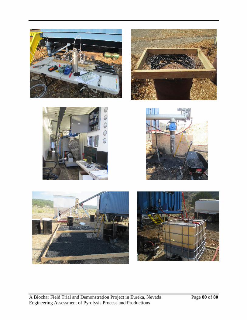
A Biochar Field Trial and Demonstration Project in Eureka, Nevada Page 80 of 80 Engineering Assessment of Pyrolysis Process and Productions