a brief tutorial on unified structured inventive thinkinga brief tutorial on unified structured...
TRANSCRIPT

A Brief Tutorial on Unified Structured Inventive Thinking
EEdd SSiicckkaaffuuss
Abstract
USIT is a simplified, structured problem solving (SPS) methodology. It is applicable in all fields of problem solving where problems can be defined in terms of objects, attributes, and functions. In its original phase of development, emphasis was focused on simplification of SPS methodologies such as TRIZ and related spin-offs. The logic of technology was the grail. In its second phase, emphasis has been expanded to suppress logic producing a broader solution space. USIT involves bimodal thinking using mental mechanics and mental strategies. Cognitive psychology research, in the past ten years, has discovered that during mental processing of information creative thinking precedes conscious logic. Once creative thinking is established as being illogical it becomes a bit too presumptive to seed the brain with logical clues – the common choice of SPS methodologies. Bimodel thinking in the second phase involves two levels, conscious and unconscious thinking. Using suppression of logic augments the scope of USIT, logic is not eliminated.
The goal of USIT is to seed the brain to employ all of its resources for generating new ideas. USIT operates within one’s mental resources of training and personal experience. Paper and pencil are the only auxiliary tools that are needed. Both phases of USIT development are covered briefly. The first phase began in Ford Motor Company Research Laboratory in 1985, the second in Ntelleck in 2000.
Keywords: conscious thinking, unconscious thinking, USIT, structured problem solving, cognitive problem solving, left-brain right-brain problem solving, brainstorming, heuristics, objects attributes and functions, OAF analyses and solutions, seeding the brain for creative concepts, conscious access, conscious threshold, point focus.

1. Introduction
I began developing USIT for use by automotive technologists with the goals of ease in learning, applying, speed, and finding multiple solution concepts.1 In the early phase of its development, authenticity for its procedures was based on the then popular two-hemisphere (left-brain, right-brain) lateralization model of the problem-solving brain. One hemisphere having a strong bent for logic while the other a strong bent for intuition.
At that time there was a concern that the LB may veto ideas arising from the RB. Publications described efforts being made to emphasize RB thinking and subdue LB dominance for creative ideas (Edwards, 1999). However the lateralization model serves a good purpose for logically trained technologists and is used throughout USIT practice.
As the heuristics2 and structure of SPS methodologies are mastered, and become automatic unconscious operations, we begin to tire of their drudgery and tedium. We gradually develop shortcuts to structure since by now they have become etched into our thinking process. This opens the door for Phase II USIT where logic is suppressed in favor of emphasis on conscious and unconscious thinking. The payoff in this transition is ready access to a broader solution space.
This brief tutorial will begin in Phase I of USIT where emphasis is placed on structures in problem solving (e.g., graphic heuristics and verbal trees). Such structures remain the essentials of USIT and their mastery is recommended. Problem examples are included in both phases.
2. USIT
This brief tutorial covers USIT’s historical development. Selected verbal and graphic heuristics are discussed to give the reader insight into the logic of USIT. Heuristics are used to
1The first phase of USIT began as SIT at Ford Motor Company’s Research Laboratory in Dearborn (1985). Three-day classes were taught in Dearborn and Ford engineering facilities in Europe and Australia. Over 1000 Ford technologists and management took three-day courses before my retirement. In addition to these classes, two-hour morning follow-up sessions addressing real-world problems were offered weekly. The second phase of USIT began at my retirement from Ford and continues at Ntelleck, LLC. I also led a four-person USIT team at Ford that was charged with applying SIT to corporate problems worldwide. We created a notebook of procedures and results for each project we addressed. Our goal was twenty plausible solution concepts per project. Multiple solution concepts were essential for project-leader options. We allowed three two-hour team meetings per project. Notebooks included invention disclosure-forms for the more unique ideas. Some of these were advanced to patent applications and eventual patents. Other companies have also provided USIT to their technologists through 3-day on-sight courses. 2 Heuristics are experienced-based techniques for problem solving.

help find the beginnings of thought paths. Introspection is encouraged to recognize them and follow them.
All USIT models are based on two objects in contact at a point. All language is based on three key words, objects (O), their attributes (A), and the functions (or effects) they support (F). Readers can measure their grasp of the methodology through immediate introspection. Ask yourself. Did the demonstrated OAF usage create in your mind suggestive images that were relevant to solving a specific problem?
This is not a question of a heuristic’s logic. It is a question of how your unconscious thinking responds to its seeding in your brain. That is, do the heuristics used here bring ideas to mind? Note that all heuristics are useful if they bring ideas to your mind when you need them. Their wording and graphics are only as critical as you require. Change them as needed. Here you are reading mine. Explore! Each problem solver has her or his way of thinking and has experience to give it life. With introspection you can analyze how an idea came to mind and can use it again. This is where new heuristics are born.
The first heuristic to understand is OAF. This is a heuristic symbol from which all of USIT methodology can be derived and many of its heuristics.
OAF Definitions: A problem can be reduced to an unwanted function (or effect) at a point of contact of two objects. Surfaces of contact are a redundancy of points; simplify a surface to a point. Two objects in contact have one attribute each that supports a function. A function alters or maintains an attribute of an object (one of the forgoing two objects or a third one). Taking attributes in pairs creates an opportunity to see a problem from a new perspective. A solution simply changes the un-wanted function into a desired one. These definitions will become clearer in examples that follow.
:
Note Problem-solving methodologies do not solve problems. Problem solvers solve problems by seeding their brains with cues to spark ideas. Different problem solvers can find different solutions from the same seeds. Therefore, solutions do not measure the effectiveness of methodologies. Problem solvers discover the effectiveness of problem-solving methodologies through introspection.
2.1 Phase I Logical USIT Heuristics

The problem statement is the most important part of innovative problem solving.
As in all problem solving, we begin with a problem statement that we create from a problem situation. Its first formulation can be very crude, verbose, and highly illustrated. This collection of information will be iterated with the goal of perfecting it into a well-defined problem. As information is collected in this step, our memories are updated for a specific job. The first version of our problem statement should contain an undesirable function (known or invented), objects, and plausible root cause(s) if known. If not known, well, we have a problem to solve. Our strategy, during iteration, will be to simplify the problem statement. Then, in subsequent iterations, continue to use metaphors at every opportunity. Building a well-defined problem statement, per the noted components, is an iterative process that can begin anywhere in an iteration loop. Introspect and record the first thoughts that come to mind.
2.11 Well-Defined Problem. In mathematics, a well-defined problem means a problem statement suitable for the methodology to be used in finding its solution. Solution algorithms are cataloged according to the characteristics of a problem. A well-defined USIT problem should contain a minimum number of objects, point of contact, focus on one problem, plausible root-causes, sketches, and expressed in an OAF diagram.
2.12 Point of Contact Point of contact is a metaphor for the contact of objects and evinces a working or broken function. You can illustrate it, or imagine it, anyway you wish in an OAF diagram. A point of contact is illustrated as a broken-line inclosing three objects and one function in Fig. 1. This triad can be used to describe a problem where F is an unwanted effect as well as its solution where F is a desired effect. Note that you need only to overlap the F’s of three OAF symbols to create Fig. 1 for the same function. For other problem situations you may use fewer OAF’s or more. You may also chain the OAF’s in various ways. (Sickafus, 1997).
Fig. 1. An OAF triad representing a problem (undesired F) or its solution (desired F) with a broken line encircling a metaphorical point of contact.
F A OO A
O A

Fig. 1 can be read as; ‘An attribute of an object interacts with an attribute of another object, at a point of contact, to maintain or modify an attribute of an object.’ These can be 3, 2, or 1 object differing only by their active attributes.
2.13 OAF Usage
Example Ex 1: Problem: How to section an orange? Solution: Slice it with a knife.
Obviously, this is a trivial problem and solution. But it serves quickly to demonstrate the use of OAF symbols. A useful practice, to gain concentration while constructing OAF diagrams, is to use nouns for O’s, adjectives for A’s, and infinitives for F’s, as shown in Fig. 2.
orange whole
knife sharp
to section sectioned orange
O A
OAF
O A
Fig. 2. Example of an OAF diagram of a solved problem. A sharp knife cuts a whole orange into sections. In this case, two of the OAF symbols describe the same object in different states; whole and sectioned are active attributes.
Writing the problem statement, using OAF language, minimizing the number of objects, finding plausible root causes, drawing OAF-triads, and making sketches is done iteratively. Begin anywhere you wish, preferably the first place that comes to mind. This starts the iterative process. Iterate as often as you think of new metaphors. Treat each new metaphor as the beginning of a thought path. Introspect for a moment why that metaphor came to mind. The time spent constructing a well-defined problem is valuable. It puts facts into your memory that augment your experience from which you will discover solution concepts.
You cannot help brainstorming ideas in the process – so don’t. Encourage it. Record all ideas that come to mind anywhere in the USIT process. Expect solution concepts even at this stage of beginning a problem solving exercise. Do the entire analysis and solution process from your memory – your storehouse of self-learning, academically gained knowledge, on–the-job training, and experience. Learn to invoke introspection constantly to speed discovering credible results.

And, by the way, brainstorm your problem before you begin USIT, to clear your head of any biases and to make the USIT process more transparent and effective.
Keep in mind that USIT is not teaching engineering (typical audiences are already trained technologists). It is teaching how to think deeply into cause and effects and to quickly find multiple solution concepts, which can be culled later for engineering opportunities. Without the bias of culling they build your library of solved problems. Furthermore, culling filters change in time.
2.14 Object-Object Diagram. An O-O diagram aids simplification by finding those objects not required for defining the problem, once you discover their relative importance. To eliminate an object, mentally remove it and ask yourself if the problem still exists. If it does, that object is not needed. Concentration on a single point of contact is an effective method of finding useful focus for object elimination. Think of O-O contacts in artifacts (man-made objects) as having a purpose. If you can’t find one, invent one or eliminate one or both objects, or unite them into one.
Ex 2: Flower and Vase. Consider the problem of finding the relevant importance of objects in a problem situation. For example: What are the functional relationships among the flowers in a vase sitting outdoors on a table, as shown in Fig. 3? The objects are flowers (simplify to one flower, then to blossom and stem), stem (independent of blossom, which has a different function), vase, water, mat, and table. Since no issue with this assembly has been identified, I’ll analyze it from the standpoint of a satisfactory design.
This makes one think of plausible design functions (purposes of all O-O contacts), those its original designer intended. Note that the word plausible is used in USIT to underscore a difference in the problem-solver’s perspective and that of the designer, whose intent is not known to the problem solver. The word is also used in plausible root-cause analysis when cause is being speculated as adequate in the problem-solver’s mind, but not yet proven.

Fig. 3. Vase of flowers and water sitting on a table.
Heuristic: Simplify similar objects to one. My simple sketch of this design is shown in Fig. 4.
blosso
m
stem
water
vase
mat
tabl
Fig. 4. Sketch of vase resting on a table, holding water and a flower. Six points of contact are encircled with broken lines.
Using introspection, relative importance of objects can be demonstrated in an O-O contact tree. Objects are arranged vertically with each subordinate object below its superior that it is in contact with. Each subordinate object must provide a beneficial function to its superior. These functions are written between the objects. Object-object trees can have multiple objects at the same level. Fig. 5 illustrates the associated O-O tree for the vase of flowers.
In Fig. 5 we see that the system has 6 objects and 4 points of contact, each point describing a beneficial function. There is no purpose at the moment for reducing the number of objects. The reason is we have not decided on a problem to address. We can’t examine root cause either for the same reason. So I’ll use this opportunity to examine the system having no problem – a system working according to its original design.

tabl
to protect
mavas
wat
ste
blosso
to feed
to display
to contain
Fig. 5. An O–O functional tree. Stem supports flower to display it. Water supports stem to feed it. Vase supports water to contain it. Table benefits from mat that protects it.
Note that I chose water to feed stem and not stem to feed blossom. That is because at the point of contact in the sketch, between water and stem, that’s what is happening. Furthermore, stem-to-blossom has at least one other function. Often you will think of several possible functions at the same point. And that causes valuable decision-making and discovery of other word metaphors – new thought paths. Using the infinitive, to (a verb), is a device to make you stop, think, and choose between whatever options come to mind.
If you don’t find the O-O tree in Fig. 5 to your liking, then modify it and make it your analysis. Did you notice that it is a somewhat superficial analysis for a botanist, for example? We could have looked a little deeper and wondered what physical and chemical processes are occurring. For example, cells in stem also consume water for their nourishment. The amount of water that stem does not use is passed along to blossom. And by what magic does the pass-along process work? It’s called osmosis.
Here’s an interesting iteration that just occurred to me. I could have inserted two kinds of water, which do exist because of their different active attributes. Let’s see what happens if I insert contained-water (c-water) and spilled-water (s-water). See if you agree with the analysis shown in Fig. 6.

vas
c-
stem
blosso
to feed
to display
to contain
s-
to ?
mat
. protect
. contain
. absorb
. localize
Fig. 6. Iteration of Fig. 5 having water divided into two objects. Mat was reintroduced to indicate something benefiting s-water – for another possible iteration. Table also could have been added to support or to locate mat.
This O-O-function analysis has revealed objects of no immediate need in the analysis; table and possibly mat. I’ll eliminate them and proceed with four objects.
At the point of contact between stem and blossom several functions came to my mind: to display, to support, to elevate, and to feed, for example. Herein lies an important heuristic for insight. Spend some introspection time at each point of contact contemplating multiple functions and then deciding on their relevance. There is no right or wrong analysis going on here. Diversity is valued. What is happening is a conscious shuffling through word metaphors, which bring new perspectives to an analysis. Different problem-solving team members will try different thought paths. That is good. And, hopefully, they will find different solution concepts. That’s good too.
When I got to blossom at the top of the O-O tree I realized that it was the most important object and what makes it that is its display. Imagine the ways the word display can spark new ideas in this analysis.
Yes, what about display? That word suggests to me two objects, one object sending information and the other receiving information – the displayer and the observer. Information, in USIT, can be an object when it satisfies the OAF definition. Information as a design object can be very informative. It is a generic metaphor with many variants differentiated by their active attributes. In this example blossom sends information to observer that benefits observer (See Fig. 7). This modification of the design description allowed me to think of different metaphors. You

can pick your own. Try it. (I didn’t take time to add the observer in the sketch. You can add a picture of a pretty person if you like.)
observer
vase
vas
wate
ste
blosso
to feed
to exhibit
to contain
informatio
observe
to display
to please
blossom
stem
water
Fig. 7. Modification of O-O-function tree and sketch to include information and observer.
For person I drew an eye. But is that the intended recipient of information. I don’t think so. Information passes through the eye’s lens onto the retina where it is transduced into a coded electrical signal, which passes on to the brain where it is decoded into an image. I should have drawn a brain, but felt I had to quit somewhere.
We now have six objects and no problem to solve. As soon as we pick a problem an O-O tree will assist in finding object relevance and from that which objects can be eliminated. So, I’ll make up a problem for this situation.
This is a common on-the-job situation that technologists face. The boss assigns a problem situation with the direction: “This system doesn’t work fix it!” Such brevity leaves the problem solver with the first step being to find out what is the problem. If you have not encountered this situation, here’s a common example. An automobile dealer sends a part, he replaced on a customer’s car, back to the dealer for repair or recycling without having diagnosed the problem. Such passing of the buck ends with the person assigned to solve the problem to figure out what the problem is.
We’ve seen how the O-O diagram can reveal desirable functions, now let’s invent an undesirable function, as a problem, and redo the analysis. In this case, we start the diagram with the object affected or responsible for the unwanted function. It’s the problem solver’s call, which object to start with. You’ll quickly discover that often you can construct more than one plausible arrangement. Remember that these are not rules and regulations. They are personal opportunities for the problem solver to search.
Now apply introspection to understand how quickly a change in metaphor can spark new ideas. To do this, change the name of an object or a function. For example vase could become container, a much more generic metaphor. Generification of words and sketches open the box of metaphors for many more examples, such as, bottle, box, barrel, carton, basket, apron, boxcar, can, test-tube, balloon, bag, purse, truck, hand, and many more for container.
We still have not defined a problem to analyze. What we have accomplished in this one simple example is to pass a series of related metaphors consciously through our brains. They will reside in short term memory while we address a problem. What will happen if we chose a problem involving the vase, and we are looking for attributes or functions related to vase, or to objects it’s in contact with? Metaphorical attributes and functions may come to mind purely without conscious effort, which were sparked unconsciously by those metaphors of vase. (Keep in mind that we used a solution heuristic to generate new metaphors – ‘generification’.)
OK, we’ve gotten to here with vase; I’ll invent a problem for vase that we can analyze. ‘The vase leaks. Fix it!’ Also, I’ll assume the problem results from a crack in the vase ruining it, letting too much water out, and creating a mess (Fig. 8). That adds a root cause to improve our problem statement.

vasewater crack
tip
Fig. 8. Sketch of a cracked vase holding some water. A broken circle indicates the cracked region as enlarged in the right-hand sketch.
The next iteration focuses on simplifying the problem by minimizing the number of objects. Obviously, the problem exists at the point of contact of water and vase. Hence, all other objects can be eliminated. As shown in Fig. 7, the function of vase is to contain water, a function not existing in the problem state.
Ex. 3: Problem statement: A vase has a crack and leaks water.
2.15 Minimize Number of Objects
The problem statement has only two objects mentioned, vase and water. Once a problem has been reduced to three or fewer objects they provide sufficient minimization to move on. It may happen in the subsequent analysis that a new object could come into play. This could happen if an already selected object is divided into parts for deeper analysis. Recall flower divided into stem and blossom and introducing two kinds of waters. It might also happen that during the analysis based on three objects a way is found to reduce the number to two or even one object. The causes of such changes may offer new thought paths.
Having brought our focus onto two objects, we need to find their attributes and the functions that they support in pairs. Both can be found using the same tool, the plausible root-cause diagram. We can choose first attributes or functions. Then use the same tool to find the other one.
2.16 Plausible root cause(s) The OAF plausible root-cause diagram is shown in Fig. 9. At this junction in our analysis we have narrowed the problem situation to two objects, water and vase. To proceed with perfecting the problem statement, we need to find plausible root causes and their supporting attributes for more focus.
To construct a root-cause diagram an unwanted effect is put at the top a tree as shown in Fig. 9. In the next row below are the objects of the minimum set. Each object is examined for contributory causes of the unwanted effect. Several causes may be identified producing branches

in the tree or deeper levels. Each cause is considered to be an unwanted effect and more causes are identified. Each branch is terminated when an attribute is reached. The lowest level causes are examined to identify supporting attributes. These are listed under each branch. Every attribute is a plausible root cause, and every cause a plausible problem, at any level. These all are points to ponder for solution concepts. A root-cause diagram template is shown in Fig. 9.
an unwanted effect
cause/effect
object
cause/effect cause/effect
object
cause/effect• attribute • • • •
• attribute• • • •
• attribute• •
Fig. 9. Root-cause diagram template. An unwanted effect tops the diagram. It has the minimum set of objects below it. Next are C/E pairs as needed. Attributes terminate each branch of C/Es.
To use the root-cause diagram for finding attributes, first fill in plausible C/Es. Then ponder plausible attributes that are active or could be activated. To use it for finding C/Es first fill in attributes that come to mind. Then search for C/E-pair causations. In both cases more examples yield more depth in the analysis and more idea generators. An example of finding attributes is illustrated in Fig. 10 for the flower/vase problem.

• (assume glass vase) • inhomogeneous melt • low melt temperature • too rapid cooling • chemical composition
• volume • phase • chemical composition • pH • molecular structure
vase leaks
vase water
internal stress
expansion incipient crack
cooling
Fig. 10. A glass vase was used for this demonstration of root-cause analysis. Cause/effect pairs were inserted in the diagram first. Then attributes were found.
As seen in Fig. 10, incipient crack could be the cause of glass-vase leaks. (That’s the first mention of the vase’s material. Were you thinking glass along?) Internal stress could be the cause of incipient crack. Low melt temperature is a plausible attribute contributing to internal stress. And so are inhomogeneous melt, too rapid cooling, chemical composition, and possible others. They wait our introspective processing.
SC01. A solution concept that arose here is to eliminate incipient cracks. Review the glass production line to see how incipient cracks might have formed. Such variables as pre-melt composition, solid glass composition, melt temperature*, time at melt temperature, cooling time, annealing time, and storage conditions are suspect.
*Strictly, temperature is not an attribute. It is a measure of internal energy, which is an attribute. But, recall that this is a personal exercise to produce inspiration. Sometimes there may be too much logic. On the other hand, making corrections for more accuracy is a useful technique for learning more science and technology. And if you are teaching, more accuracy leads to fewer student complaints.
SC02. A more specific solution concept arose from the combination of too rapid cooling and composition. These conditions can lead to chemical entities precipitating out of, for example, a water/ice phase at low temperatures. Localized accumulation of precipitates can be sources of stress concentration. Concept: Retard cooling rate.
Note that vase material was not specified until Fig. 10 where glass was assumed as an example. The generic nature of our analysis allows us to easily use the same general analysis for different vase materials. Recall how many different kinds of container have been identified. There obviously can be many kinds of metaphoric vases and associated materials. This would be a useful assignment for a class, that is, to pick a different container material and rework the analysis.
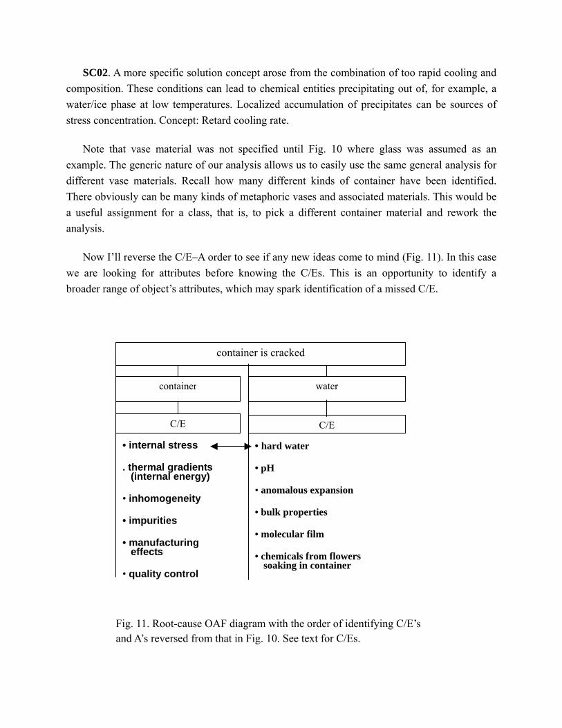
Now I’ll reverse the C/E–A order to see if any new ideas come to mind (Fig. 11). In this case we are looking for attributes before knowing the C/Es. This is an opportunity to identify a broader range of object’s attributes, which may spark identification of a missed C/E.
• internal stress . thermal gradients
(internal energy)
• inhomogeneity
• impurities
• manufacturing effects
• quality control
container is cracked
Fig. 11. Root-cause OAF diagram with the order of identifying C/E’s and A’s reversed from that in Fig. 10. See text for C/Es.
container
C/E
water
C/E
• hard water • pH • anomalous expansion • bulk properties • molecular film • chemicals from flowers
soaking in container

A C/E of internal stress and hard water is the precipitation of salts of calcium, for example, in the entrance of an incipient crack, which could cause thickening of wedge of solid material and exacerbate failure.
Note that container was used as an object and not crack. Crack is not an object; it’s an attribute of an object’s shape, continuity, or other. But, again, use wording meaningful to you.
One value of this root-cause tool is its printed layout of attributes where one can examine them readily for pairing and new thought paths. I noted that pH and inhomogeneity brought to mind that specific ranges of pH might attack local regions of inhomogeneous material. These could be points of stress created by etching and weakening of incipient cracks. Hence pH of water and impurity of glass causes etching, which produces stress points and exacerbation of growth at incipient cracks. Plants soaking in water might shift the neutral pH of water.
SC03. Determine which, if any, plants modify pH of water such that it might cause etching of glass at incipient cracks.
SC03.1 Place informative label on vase packing to caution users (corporate protection).
SC04 Coat class with protective material to reduce susceptibility to etching.
SC05. Internal stress can be caused by the anomalous expansion of water at low temperature. In cold climates, store vases in warm environments. Advise users accordingly.
Warning labels do not address directly the problem statement. Yet the idea came to mind. It must have been an unconscious idea – reason for grabbing every idea as it comes to mind.
Reasons for these O-O parings are: water’s anomalous expansion on freezing could have cracked the vase, say, during outdoors storage in the winter; An air-born object may have struck the vase. An incidental shock by an unidentified object may have caused sufficient impulse to cause a crack at a stress-concentration point.
A simple model of a crack is a gap that decreases in size to molecular dimensions as the gap tapers to a point. In the closed-end region of the crack water is no longer in bulk concentration. Consequently, a model suggesting anomalous expansion, a bulk property, is of no use inside a crack. We now need to think of unwanted effects on a molecular scale. In fact bulk expansion may be an issue only at the outer extremities of a crack. If a network of incipient cracks exists in the surface region of an exiting crack, high stress could lead to spalling of microscopic particles

of glass. In this region, bulk expansion of water could be a concern. We need a different model for the region of a crack having molecular dimensions.
We know that water molecules are very mobile at freezing temperatures because ice whiskers are known to grow on ice cubes in a refrigerator. I’ve grown them and photographed them. This observation is useful for me to be able to pose at least a plausible model for water in molecular scale cracks. Technologists do this frequently as problem solvers; personal experiences help to imagine their extensions to other situations, thus expanding solution space. In this case, molecular layers of water on glass at freezing temperatures have several possible phases (the nature of water). Which means that water molecules could nucleate in different phases near the same temperature. Nuclei will have different dimensions according their phase. Hence, I conclude that water nuclei should be considered in any cause-effect analysis (that I do).
SC06. Nucleation of ice on inner surfaces of a crack can exacerbate crack growth. Hence, coat container to make it water proof.
The purpose of root-cause analysis in USIT is to dig deeper into cause-effect phenomena in search of more fundamental causes and thought paths. This stretches one’s thinking to the point of imagining what might be possible. Here may lie big payoffs.
If a plausible root cause is not known to be true good things can happen. It can send the problem solver to search the literature or find a specialist for corroboration of an idea. An opportunity for a patent application may accompany corroboration. Opportunities for discovery through research my result from finding that the idea is new and unknown.
2.17 Cause-effect analysis
There is a neat method for expanding the root-cause diagram for more insights into a problem. Begin with the Effect-Cause elements and stack them as needed. In the first level of E/C pairs is placed the unwanted effect, a problem, and beneath it a plausible cause, as shown in Fig. 12. Next place a second E/C pair with the upper C adjacent to the lower E.

problem
cause
effect
cause
…
attribute
Fig. 12. Cause-effect tree with adjacent cause-effect unions. The C/E unions, shown by arrows, indicate to convert a cause into an effect for its now subordinate cause. These pairs can be continued as one’s imagination warrants.
Focus is on successive E/C’s leading one to deeper root causes. This structure carries our minds into areas we might not thought of visiting (See Fig. 13). When an effect cannot be converted to a deeper cause it becomes an attribute.
SC07. Thin film water in crack may be removed by heating glass to temperature approaching boiling, raising its vapor pressure, and speeding evaporation.
solidity
to expand
to change molecular geometry
to crack
to minimize energy
to nucleate
Fig. 13. Cause/Effect tree for a cracked flower vase.

To-crack is caused by to-expand. To-expand is caused by to-change molecular geometry (bond length and/or bond angle). To-change molecular geometry is caused by to-minimize free energy. To-minimize free energy is caused by to-nucleate, which accommodates a molecular-scale solid film. Solidity of the nucleated film is the final attribute.
SC08. A solution idea came to mind here. Eliminate bulk water in a crack, such as, by heating or holding in a low-pressure container.
SC09. Prevent chemical attack of incipient cracks by coating glass during manufacturing with a hydrophobic layer.
2.18 OAF statements An OAF statement is another tool for finding root causes, as well as expressing problems and solutions. Consider the problem example in Fig. 14.
water attributew
to crack
attributevvase
Fig. 14. A two-object OAF problem diagram. Attributew is an attribute of water attributev is an attribute of vase.
We can rearrange this diagram several ways to make room for adding lists of attributes (Fig. 15). The attributes need not be limited to pairs at this point. Simply list attributes, active or not, as they come to mind and then later pair them randomly. (There is room for your ideas.)
attributev٠ incipient cracks, ٠ inhomogeneous
material, .
attributew ٠ anomalous expansion of water on freezing,
water to leak vase
Fig. 15. Rearrangement of Fig. 14 for ease of listing attributes.

One more feature is needed for a well-defined problem, namely simple sketches. You have already seen examples of these in the forgoing discussion. They are an essential part of problem definition and can vary widely between problem-solving team members. Sketches are a part of our language of communicating with our unconscious level of thinking. It has been demonstrated that simple stick figures can prompt innovative thinking (Finke et al, 1996). When making a sketch, if not in your conscious, at least your unconscious will be noting O-O contacts.
Enough information has been assembled for a first draft of a well-defined problem as discussed in the next section. And we already have solution concepts.
2.19 Information as an Object
Information is probably the least familiar object metaphor to a new learner of SPS. Its flexibility is striking. Consider the following sample sentences.
1. When a key is turned in a lock, information is transferred. 2. When a needle pricks the skin, information is transferred. 3. When a scanner swipes a bar code, information is transferred. 4. When a hand turns a steering wheel, information is transferred. 5. When a cat hisses, information is transferred. 6. When a bird sings, information is transferred.
Take a few moments of introspection to note how these examples of an object metaphor make sense. What images came to your mind? Did you find more than one image for the same metaphor? Note the variance of new objects, attributes, and even functions you thought of. Now construct problem statements or solution statements, one for each of these metaphors using C/E trees.
2.20 Focus on one problem
This has been a drawn-out discussion of constructing a well-defined problem. That happened because at most opportunities I digressed to discuss solution concepts that came to mind. This is actually the way USIT works. By writing down ideas as they come to mind they affect the subsequent analyses in a constructive manner. The usual process in SPS is to develop a well defined problem then proceed to solution strategies (See USIT flow chart, Fig. 19). With
practice, you may find yourself spending most of the time in the well-defined problem stage. And sometimes you may finish the whole exercise there.
The power of focus on one point is rather remarkable, especially when first experiencing it.
2.21 Sketches
Sketches are an inseparable part of problem definition, analysis, and solution. I’ve been using them all along in this discussion. It shouldn’t require much more to convince one of a sketches’ importance. The topic has been added because my experience in leading USIT and fresh-eyes problem-solving teams I’ve become aware of a reluctance of some technologists to make sketches. Often such reluctance is caused, I suspect, by simple embarrassment for lack of artistic skill (Edwards, 1999). I would encourage each reader to resort to the simplest of sketches, even stick figures, and discover their power as metaphors. A stick figure is the ultimate generic metaphor of a person. Our brains are amazingly good at interpreting the language of simple art, both with logic and with intuition.
2.22 USIT flow chart
The Phase I USIT flow chart is shown in Fig. 16. Most of this brief tutorial has focused on the heuristics shown on left side of the figure.

Fig. 16. Phase I Flow chart. All analyses start wit problem definition, albeit a rough draft to be iterated. (Bolded topics discussed in the ICSI&GCSI symposium lecture)
As these plausible causes came up, for the vase of flowers and before any analysis, so did plausible solutions. So in keeping with the urging to record solution concepts as they arrive, here are the ideas I had immediately on writing the problem statement.
The first idea is to trash the cracked vase. It may be worth more in recycling.
The second idea is to ignore it until the vase fails completely and then dispose it.
The third idea is to repair it (using glue, tape, or seal the crack by annealing the vase in a furnace where additional glass could be added to the crack).
It has been demonstrated that OAF is broadly applicable metaphor from which all the tools of USIT can be constructed – a useful reduction of structures to memorize. The symbol and its definition is all a USIT problem solver needs to begin problem analysis and solution. The
USIT Phase I Flow Chart of Heuristics
Well Defined Problem
∗ Problem statement
∗ Root Causes
∗ Select objects
*Particles Method
∗ Morph cartoon
∗ And / Or tree
∗ Apply particles
*Closed World Method
∗ CW diagram
∗ OAF statements
∗ Qualitative-change
graph
*Solution Techniques
∗ Simplification
∗ Uniqueness
∗ Dimensionality
∗ Pluralization
∗ Distribution
∗ Transduction
∗ Generifcation
∗ Metaphors
*Order of application is not important
Items not covered in ICSI&GCSI symposium

definition of OAF: Objects in contact each has an active attribute, which supports a function that maintains or modifies an attribute of an object.
2.23 Solution Strategies. Solution strategies also are evident upon blowing up an OAF triad, as shown in Fig. 17.
Fig. 17 Graphic representations of solution strategies. Broken-line circles mark points of focus.
Solution strategies represented in Fig. 17 all concern the grayed F, which is an unwanted effect, a problem. The following list shows ways to break this definition of a problem, which then represents where to search solutions.
O A
O AF A O
1. Grey O represents to eliminate or change an object, any object in the diagram. 2. Gray A represents to eliminate, change, or alter the metric of any attribute. 3. Gray F represents to eliminate it or change it to a desirable function. 4. Gray bar represents to eliminate or alter the metric of any graph connector.
Elimination of an object, in a closed world, suggests causing one of the other objects to take on its function. Activating an attribute in the new object can do this. Eliminating an object might be done by replacing its attribute with that of one of the other objects. Altering a metric of an attribute refers to changing its magnitude, intensity, duration, etc. Changing an unwanted function means to make it work for you. Note that these are solution strategies not solutions. They show where to focus your efforts and they offer multiple opportunities of solving a problem. For more on graphic-solution strategies see (Sickafus, 2006).
The flower/vase problem was developed using 2 sketches and 4 structures, an O-O-function diagram, root-cause diagram, a C/E tree and an OAF problem statement. These structures also gradually become etched in to one’s unconscious memory and are easily omitted from conscious thought. I still find the sketches worth the effort to construct.
2.24 That’s It! A Brief Tutorial That Has Shown All Details of the Example Problems

W
Bu
hile the text of this manuscript has been written and edited in iterations the examples of applying heuristics are the original notes as the problems and their analyses were executed. Text was typed and edited in a word processor up to an example problem. At that point editing ceased as the problem was solved, for the first time. Sketches were drawn with some editing. Then writing and editing of the main body of text continued. This is my customary way of solving USIT problems. It keeps my aging brain in practice.
t what are you to get out of that paragraph? I had hoped to demonstrate how little SPS methodology is needed in a formal, or logical, sense once the methodology has been ingrained in one’s memory. However, as I think about it, I have no idea how much or what part of formal USIT was exercised unconsciously. My understanding of the two level brain model is that most thinking is done in the unconscious and the conscious does the logical organization for communication purposes. I have no access to my non-communicative unconscious to pose the question. So, I’m back to the realization that my introspection convinced me of the utility of the two-level model of the thinking brain. Now I can only look for feedback from fellow problem solvers who have tested the model with their own introspection.
3.0 USIT Phase II
Development of structured problem-solving methodologies, in the past and up to around 2000, has based all heuristics on logic of the technical mind. This includes all of USIT Phase I verbal and graphic heuristics. The rationale for this, at least since the 1950’s, has been the lateralization of the brain into left-brain preference for language and logic and right-brain preference for intuition and metaphor. Rational thinking, as a basis of SPS, was not a consciously agreed upon decision. It arose, and still arises, automatically as a result of the indoctrination of science. Logical thinking and science are mutual metaphors. I suspect that all technologists are conscious and proud of their personal abilities in logical thinking – the grail of technology.
Now, in the past ten years, comes a new model of thinking from research in cognitive psychology. A two-level model of brain function, conscious and unconscious (or subconscious), is being used in which conscious processing plays second fiddle to unconscious processing.
One fascinating aspect of this research is the discovery of the time scale of these two types of mental processing. On receipt of a signal the unconscious is already at work within one millisecond while conscious processing may not begin until 300 milliseconds later (Dehaene, Stanislas, 2014).

These are the first quantitative measurements of age-old suspicions about brain functions. For example, physician Galen in Roman antiquity recognized unconscious human action (ca. 129-200). The importance of the unconscious is key to recent expansions of USIT. Here is a relevant quote from Dehaene’s book, ibid.
“How deep can invisible image travel into the brain? Can it reach our higher cortical centers and influence the decisions we make? Answering these questions is crucial to delineating the unique contours of conscious thought. Recent experiments in psychology and brain imaging have tracked the fate of unconscious pictures in the brain. We recognize and categorize masked images unconsciously, and we even decipher and interpret unseen words. Subliminal pictures trigger motivations and rewards in us-all without our awareness. Even complex operations linking perception to action can unfold covertly, demonstrating how frequently we rely on an unconscious ‘automatic pilot’. Oblivious to this boiling hodgepodge of unconscious processes, we constantly overestimate the power of our conscious in making decisions-but in truth, our capacity for conscious control is limited.”
Consequences of the latest cognitive, neurological research have been incorporated in Phase II USIT. This is done through a purposeful shift away from conscious seeding of one’s brain to unconscious seeding. Why and how this is done is covered in this section of the manuscript.
3.1 The Unconscious/Conscious Bilevel Model of the Brain
The first aspect of the latest cognitive-psychology research of importance in USIT is the huge time separation between unconscious mental processing and conscious processing, a factor of ~100. It takes only a little introspection to recognize how quickly ideas pop up in our conscious with no apparent reason. Lying beneath the conscious threshold (CT), this is clear evidence of the work of the unconscious. It also takes little effort to recognize how long it takes a logical seed to cause awareness of its result; e.g., recall of a name using a pneumonic like stepping through the alphabet. Lying above the CT, this shows an inherent delay of conscious vetting of unconscious thoughts.
Unconscious, operating below the CT, gathers many ideas without the aid of the conscious vetting. Hence, it is expected that these early ideas will be a mix of logic and intuition. These unvetted, first fruits of seeding should be valued for their potentially broader scope of solution space.

While the unconscious is rapidly recognizing and categorizing ideas, deciphering and interpreting words, the conscious is tediously vetting its suggestions so that logic prevails. I use this result of research to pose that no delayed vetting be in USIT and to capture the first ideas that come to mind. This is a personal ability we can develop to some degree with introspection. Personal no delayed-vetting is analogous to no conscious filtering of solution concepts commonly practiced in team-type problem solving, though the two operate on different time scales.
The concept of “…conscious access – why some of our sensations turn into conscious perceptions, while other remain unconscious” (Dehaene, 2014) – is explained in part by the existence of threshold conditions separating unconscious and conscious perceptions. Threshold is defined as when the same image is perceived consciously only half the time. This time gap – time to access – opens with a minimal time to awareness. I think this is where faint, first ideas occur (missed access opportunities) that may be accessed after an intervening distraction, possibly of extended duration.
Perhaps the most significant deduction from realizing that the unconscious is already busy finding concepts before the logical conscious starts working, is that creative thinking is not logical. The logic arises only after conscious access. In the intervening period the unconscious is rapidly finding potential bits of information that the conscious gets fleeting glimpses of and occasionally accesses its preferences. Until access occurs, which is a logical process, unconscious is making random associations without the control of logic. Ergo, unvetted, random associations of internal knowledge are the earliest character of innovative thinking.
It is tempting to refer to this as illogical thinking. But it is conscious thinking that vets and assembles the relevant ideas coming into the conscious. From this effort comes two levels of communication; the first being the internal rationalization of thought and the second being external communication.
3.2 A New Model of Bilevel Thinking.
To begin adopting the two level model of U/C thinking we need to understand seeding of the brain. Phase one’s logical concept of seeding is that the specific assignment of problem-situation words for object, attribute, and function sparks metaphorical associations. These associations with knowledge stored in memory can lead to solution concepts. That they are narrowly tied to a point of focus in the problem assures their relevance. Justification for this view was given in

cited research in cognitive psychology (Finke, et all 1996). A somewhat weak side of the Ph. I model is its assumption that the product of a seed is right-brain intuitive association with memory that relies on left-brain vetting and editing for logic. That is, logic comes late. We now need a new model, one that doesn’t stress logical metaphors.
I note that there is no a priori reason to require logical concepts from a seeding of the brain. The first requirement is to spark concepts without such filters. Later processing can decide how to deal with them.
Several characteristics of U/C processing are noted (§3.0):
• Recognize and characterize masked images unconsciously. • Decipher and interpret unseen words. • Subliminal pictures trigger motivations and rewards without our awareness. • Complex operations linking perception to action unfold covertly. • We overestimate the power of conscious in making decisions – capacity for conscious
control is limited.
The time constant to conscious access is ~100 times longer than unconscious processing.
These characteristics of U/C processing bring to mind useful modifications of seeding for Ph. II USIT.
Unconscious, logical processing of seeds is initiated, essentially, instantaneously including the interpretation and recognition of words and images. Furthermore, it is not delayed by access threshold time. This is an invitation for broadening searches of solution space by not emphasizing logic.
While logic in problem solving is an assumed requirement by technologists, what that means in innovative thinking has not been defined. One assumed useful aspect of logic is to filter ideas with respect to relevance. But, ideas spark other ideas and even seemingly bad or whimsical ideas can be edited into useful concepts. This perspective on problem solving favors squelching logic in favor of finding many more ideas, which can be edited later in engineering.
3.3 Concepts Seed New Concepts

Ex. 4:Problem Situation: New hand-cream dispenser design is needed. Sales are lagging and management wants new product design. Attractiveness is the main issue; internal mechanical pump and plumbing work fine.
Problem statement: Design an attractive liquid dispenser. (This is a non-logically structured problem statement. It has no complete OAF language.)
A lot of freedom is available to the problem solver in this statement, like a clean sheet of paper problem. Two criteria are mentioned, ‘attractive’ and ‘no new plumbing’. Attractive has several definitive handles; image, shape, heft, color, pattern, scent, grasp, taste, size, and others …
Assumption: I’ll assume that shape must be an important first impression, and all other handles can be treated as secondary modifications.
Original product; tilt to aim, press to spray.
Simplify shape for more attractive design.
Add directed nozzle toeliminate need
3. Eliminate plumbing, hinge lid, add roller ball for finger-wipe

Fig. 18. Example of stepping-stones: concepts seeding new concepts. These ideas flowed readily as each new drawing was being made.
Consider an example of how seeding can be made less logical.
Non-logical seeding. Paper cups of water are too often knocked over spilling their contents and making a mess. This simple statement contains both defined and implied OAFs. It is ready for Ph. I type analysis. Suppose we eliminate the words paper, cup, water, spilling, and mess and now take a much more metaphorical examination of the inherent problem including metaphorical graphics.
Problem: A resting container, [], of fluid, ▒, becomes unstable when met by a lateral force. (Resting implies balanced reaction to gravity.)
Sketch: Lateral force, , encounters balanced gravity.
This dish of vectors is ready for an engineer to devour. It is readily imagined with no further visual cues and with no object! Yet, it is a readily understood metaphor. Here are quickly found solution concepts:
Strategy: Since gravity is already balanced, counter [▒] with co linier producing [▒] .
Solution concepts:
SC10. Stiffen container to provide adequate reaction: change material, thicken walls, add a container liner. (4 ideas)
SC11. Add a lip on top of container to raise minimum tilt angle for spillage (increases CG).
SC12. Add lid to prevent spillage.
SC13. Solidify fluid contents to minimize spillage.
If causes a torque due to friction between container and support surface,
SC14. Lower its center of gravity by changing shape of container.
SC15. Add weight to container: thicken base, add balls, chips, etc. of material denser than fluid contents and chemically benign.

Yes, that would displace some of the contents and might require larger containers. O.K. But that’s an engineering concern. Isn’t it? Hence, it’s a filter at this stage of problem solving and is to be ignored.
SC16. Increase coefficient of static friction of container support.
SC17. Reduce sliding friction so container slides before tipping.
SC18. Use a spherical container, with an off-center CG, so it can return automatically from large angle displacement to rest without spillage.
SC19. Set container in a recess in its supporting surface.
SC20. Use to close a lid.
SC21. Use a gimbal. Change support point to two points on an axis through the object’s CG. This allows one degree of angular rotational motion for body shapes that can allow the lateral force to change the body’s angle.
Obviously, these solution concepts were strongly affected by the full problem statement preceding the removal of the words paper, cup, water, spilling, and mess. Yet they produced ideas applicable to undefined containers – a larger solution space.
It is interesting that no particular object shape was needed. Its CG was the focus of vertical forces, which need a point designation. The lateral force, the horizontal arrow, can be moved mentally to different vertical positions as other reactive forces are contemplated.
By introspection we see that we have invented a new heuristic for Ph. II USIT.
Heuristic: Create a well-defined problem statement by changing the components of an OAF statement into unclear, or drastically generic metaphors.
3.4 Comments on access of images.
One example, of a missed access opportunity occurred when I was quickly grabbing several stacks of papers from my desk and tossing them into a wastebasket. A brief thought occurred that a sketch of a bird I had published may have been in one of the stacks. I proceeded without giving

it a second thought. But I did recall that brief idea a week later when I needed to find the sketch. It was long gone.
I wonder if this seemingly instantaneous recall of a week old brief thought suggests time-delayed successful access? This time the formerly brief thought had time to turn into conscious perception.
A second example, of a faint, first idea, happened when driving to breakfast one morning. As I approached an intersection, where I may turn one way as often as the other, I began rotating the steering wheel to the left; a quick thought occurred that this was wrong. Yet, I ignored it and continued the left turn. A few blocks later, I discovered that I had made the wrong decision. And with that thought I recalled the missed access of the correct thought.
Such missed access experiences are my rationale for making the recording of first ideas in problem solving a USIT heuristic. The payoff is the subsequent broadening of solution space. Unvetted first faint thoughts, if we can capture them, offer expansion of our working solution space. Since, ‘capture’ implies a level of consciousness, ‘first faint’ must occur in the threshold region of time. Hence, there is a need to sharpen introspection threshold by capturing first thoughts.
Missed accesses seem to be more common for me when I am driving a car. Today, as my wife and I were driving across a small bridge on our street my wife asked, as we drove off of the bridge, “Did you see the flowers?” “Yes I did.” I replied. Then, instantly I had the realization that I had responded to, “Did you see …”, without having heard the last two words. Actually it did not register in my mind until she asked the question. Then a faint image of a pot of red flowers became visible in my mind. The image was in the extreme right-hand side of my peripheral vision. It took less than three seconds to cross the bridge and I kept my head facing straight ahead to attend to children and bicycles. This fleeting faint image did not become accessed until my wife spoke.
On review, I think I understand how the sudden recall happened before I heard the words, “… the flowers?” A reference already existed in memory. A year ago today, Memorial Day, we crossed this bridge, saw pots of flowers and discussed them. It was an unusual sight because the rest of the year flowers are never on the bridge. Consequently, we discussed it and wondered which neighbors living around the bridge put them there.
Access of images was a new concept to me that caused some pause to reflect on my own identification with the concept. Apparently my bent for logic fought this concept until I found

examples in my own experience. Once that happened I quickly adopted it to USIT. From my missed access opportunities I have become convinced of the validity of access of information and all of its trimmings.
3.5 Where Logic Stands in Innovative Problem Solving.
If on reading this publication it seems that logic has been downgraded and is being denigrated as a valid factor in problem solving. The former is true to some degree the latter is not true. What has happened is that from cognitive psychology research it has been learned that conscious vetting of ideas for logic has been overrated and misplaced. A new bilevel model of thinking credits the unconscious with rapidly discovering metaphorical associations of queries with memory. Some of these may be logical and some may not. They are found and proffered to the conscious, which is far slower in recognizing and responding than the unconscious.
Logic follows with conscious vetting of unconscious discoveries. Consequently, conscious perception becomes the source of logical entries in the folio of solution concepts. Its contents for a particular problem-solving exercise may contain only part of the original collection found by the unconscious but subsequently culled by the conscious. What conscious perception does get cataloged is the realm of logical solution concepts we have always dealt with.
Fleetingly processed ideas, and rejected ideas, never accessed may be missed. The may be missed concepts are, so to speak, the realm of the unconscious. It is in this realm we wish to gain access to the unseen, unvetted concepts with new heuristics that eschew logic. I am assuming that this is at least one proper place to eschew logic. It can be accomplished by bypassing much of the structural heuristics of SPS methodologies. If successful, unvetted concepts become new entrees into solution space. These unvetted concepts can the be used as stepping stones to yet other concepts with the expectation that pay dirt of bright ideas still exists.
In summary, logic is still used in USIT with the same heuristics and focus on logic as in the past. However, the unconscious/conscious bilevel of thinking model is adopted also. In Ph.II USIT logic is suppressed and most of the logic tools of Ph.I USIT are omitted. With these two phases of USIT we are improving the quality of the seeds we use to inspire innovative thinking. I have introduced several heuristics designed for the purpose just described.
3.6 USIT Phase II heuristics:

As in Ph. I, all problems begin with a problem situation followed by a problem statement that is, by iteration, developed into a well-defined problem. While in Ph. II, we begin with a problem situation and develop it into a problem statement, but we do not work toward a well-defined problem. Rather much time is spent gathering relevant information (feeding our memory) and developing solution concepts in the process.
USIT Phase II Flow Chart of Heuristics
Problem Definition
∗ No strict OAF
language
∗ Generic metaphors
Solution Techniques
∗ Simplification
∗ Grab first ideas that
come to mind
∗ No logic filtering
∗ Stepping stones
Fig. 19. USIT Ph. II flow chart of heuristics. Solution techniques of Ph. I are also applicable in Ph. II.
I developed four heuristics to characterize the USIT process in Ph. II.
1. Gather problem-situation information at some length while simultaneously developing solution concepts

2. Omit as many OAF references as possible; e.g., use no formal OAF problem statement.
3. Develop a well-defined problem statement then change the OAF components to unclear or drastically generic metaphors.
4. Use each idea as a stepping-stone to new ideas
3.7 Comments on Pre-Engineering Solution Concepts
There are several reasons why simplification of SPS methodologies using USIT is so efficient. The burden of structural heuristics and the time spent in analysis is greatly shortened using USIT. Another reason is that solution concepts are just that – meaning that they are not fleshed out engineering concepts. They take less time to record.
This simplification resulted from my experience at Ford Motor Company in leading ‘fresh-eyes’ teams in off-site problem-solving tasks. It was quickly recognized that the participating technologists were all capable engineers and scientists. They had no need for more technical training. What they needed and appreciated was learning new methods for innovative thinking. Two issues stood out. How to quickly organize and start solving a problem, and how to invent new concepts.
3.8 How Can We Know Our Unconscious is Solving Problems?
Suppose a policeman pulls you over and asks, “Do you know why I stopped you?” I imagine a number of responses arise quickly in one’s mind for the ‘why’; some may be too smart for the occasion, and others you are mentally shuffling through to find the best one. But what about the word ‘know’? My sheepish reply is, “Well, I guess I can’t say I know but I suppose I was … (your answer is as good as mine)“.
This question of knowing comes to mind when, in the process of successfully finding solution concepts, the thought occurs, ‘How do I know USIT solved or aided in solving the problem?’ The reason this issue arises is, as I have just gone through, unconscious solutions concepts are just that – they are unconscious! Knowing, i.e., having made conscious access, takes ~100 times longer to establish. And the answer is? I don’t know!
Without knowing the next resort is to be convinced, first through introspection and then by the metric of results. While self-satisfying, especially through multiple instantiations, it lacks independent corroboration. Such corroboration is not to be expected from discerning problem solvers. Think about it. All unconscious solution results are the jurisdiction of the non-communicative unconscious. We are left with introspection. Thus, I conclude that the best corroboration is the results of introspection shared within the community of experienced structured problem-solvers.
4.0 Addenda
Two addenda are placed here to speed the access of experienced SPS practitioners to the main body of this tutorial. This section is introductory to USIT. Addendum 4.1 is an introduction to the OAF language of USIT through a real-time example of applying USIT. This addendum constitutes the main core of the invited lecture by the same title.
4.1 Introductory Example of a Real-World Problem for those not Familiar with SPS
For those not familiar with SPS methodologies a brief overview may quickly become too brief and too abstract. I suggest that before going into theory it might be helpful to jump in and solve a simple, real-world problem. To this problem we will apply a sample of USIT’s heuristics.
4.1.1 The Problem
Ex. 5: Problem statement: Here’s the first problem to come to my mind; develop an orange peeler. I consciously thought of this example while writing this section. It’s intended to display a real-time problem-solving process, with warts and all. Please make note of your own ideas as we proceed. Note the minimal use of structured heuristics in this exercise. Compare that with your experiences using SPS methodologies.
Problem analysis
Problem analysis begins with developing a well-defined problem statement. The process is an informal, conscious analysis involving unconscious inspirations.

Where and how to start a problem has been a stymie for many individual and team problem solvers. Obviously, we need to start with a problem statement that adequately contains the problem. As the orange peeler idea came to mind it was accompanied with an image that contained the problem in detail. It was an image of my hands holding an orange and a paring knife with a ragged peeling that contained patches of orange pith still attached to the rind. It was not a clean peeling of the rind. Consequently, juice was oozing from the places on the orange where the knife had cut too deeply into the orange pith. Here’s a first try at a problem statement. Iterations may follow later.
Problem statement: Paring a hand-held orange with a hand-held knife produces a non-uniform peeling with messy juice oozing from cuts made too deep into the pith.
This seems to be an adequate statement and even captures a root cause; namely, cutting too deep. A simple sketch is shown in Fig. 20.
right-hand
left-hand orange
pithpeel
juice
knife
Fig. 20. Orange, orange rind, knife, dripping juice and fingers (black lines) are shown. One set of fingers is holding the knife and the other set is holding the orange.
That sketch is a bit confusing. So now that you’ve seen those black-line fingers, I can eliminate them. None of us will forget them. That, by the way, is a bit of information about bimodel thinking. The conscious may soon forget the fingers, but the unconscious will recall them when needed.
Here’s a simpler sketch to work with.
orange
pithpeeling
juice
knife

F
ig. 21. Simplification of Fig. 20 with fingers of hands removed.
My first solution concept came to mind as I was making the sketch:
SC1: 3 Use a small scoop-shaped cutting blade to pare more easily smaller thickness peelings. (It looks like my unconscious quickly thought of an ice cream scoop.)
scoop & handle rind pith
Fig. 22. Scoop having a sharp edge and fixed handle allowing peeling with scooping motions, rock-and-cut motions, to remove pieces rather than strips of rind.
Further expansions on this solution concept came quickly to mind as strategic ideas.
SI1: Use a rim-like guide on the scoop to control the depth of cutting by adjusting the angle of the handle. This involves hand-held tilting with visual feedback to control cutting. The scoop is circular in cross-section so its depth at the point of contact with the rind is adjustable (an elliptical shape would also work). The edge of the scoop is sharp. This may require a cover over the scoop to protect user fingers.
3 SC refers to solution concept. SI refers to strategic idea.

I realize that this is not a fully developed solution concept, so I’ll call it a strategic idea.3 Rim is too generic of a word to represent a solution concept. Will it be a separate piece, a ramp-like shape lip, or something else? I’ll mark that in my mind as another problem to be dealt with (using USIT). This can be done later. It clearly is a plausible start. However, this is a brief tutorial. So I’ll move on to touch on more USIT structures to see if more ideas pop up.
But, in passing note that, any engineer can run with this strategic idea and produce multiple variations of it. Since engineering of solution concepts is not the goal of USIT, it makes more sense to move on in search of more concepts of wider variations. (You might find it interesting to flesh out in more detail.)
On writing the above comments, I noted that the original sketch (Fig. 20) has the knife blade placed flat on the orange with just enough tilt (not evident in sketch) to allow slicing. In this sketch the cutting edge of the scoop could be linear, curved, or a sharp point. That thought led to a roller cutter.
SC2: Use a roller blade with thick washers on each side of the blade but smaller in diameter than the blade in order to limit blade penetration. (Like a pizza pie cutter but with washer depth-guides added. A pizza cutter is designed to cut through to a hard surface.)
The cutting edge had gone from the edge of a nearly flat blade to the edge of a vertical disc in one step. It was an unconscious event that I didn’t notice until later. This allows the user to cut strips, triangles, and random shapes. Small pieces could be removed for making areas in the rind for engaging fingernails. I became aware of this change in blade shape only on second reading -- evidence of unconscious thinking.
Now that two cutter angles have been recognized what about other in-between angles? Is that another degree of freedom to be explored? I’ll leave the answer to the reader to look into.
Team problem analysis. When students sign up for a USIT class they are asked to bring two real-world problems to the first class. One should be a problem having a solution but in need of a better one. The other should be a problem having no solution – a clean sheet of paper opportunity. These problems are then used as exercises in three-person teams.

The first problem can represent a technologist’s situation in a manufacturing company. The company gets word that a competitor is going to introduce a less expensive version of one of its valued products. What is it to do? It has investment in equipment and trained people to produce this product. Hence, it would like to compete without loss of its investment. Such problems can be thought of as ‘closed-world opportunities’. That means that the problem should be solved with existing investments, or as nearly so as possible. That condition is a filter already hanging over our heads. Nonetheless, it will be ignored as a filter but approached by starting with the current product. One way to do this is to make the product more desirable by adding a new function (or effect). This often is an up-front opportunity for inventions.
Some formal analysis may be useful at this point. I’ll try characterizing an artifact in order to analyze it. In our example, we are dealing with a paring knife. A neat heuristic for such analysis is a graphic statement using objects, attributes, and functions in a triad of OAFs.
Heuristic Describe a point of contact using OAF language.
object1 – attribute1 \
function – attribute3 – object3 /
object2 – attribute2
O-A \ F-A-O / O-A
Fig. 23. OAF-heuristic template abbreviated (left) and populated with generic definitions (right). The broken line encloses a metaphorical point of contact of the objects. Eliminate spatial issues and think of the whole group as existing at a point.
Using the problem statement, we can fill in this graphic for its designed function as shown in the following figure. The point of contact is where the function (or effect) takes place and results from two attributes which cause the affected one to remain the same or change.
Heuristic Populate an OAF point of contact in stages with intervening analysis.
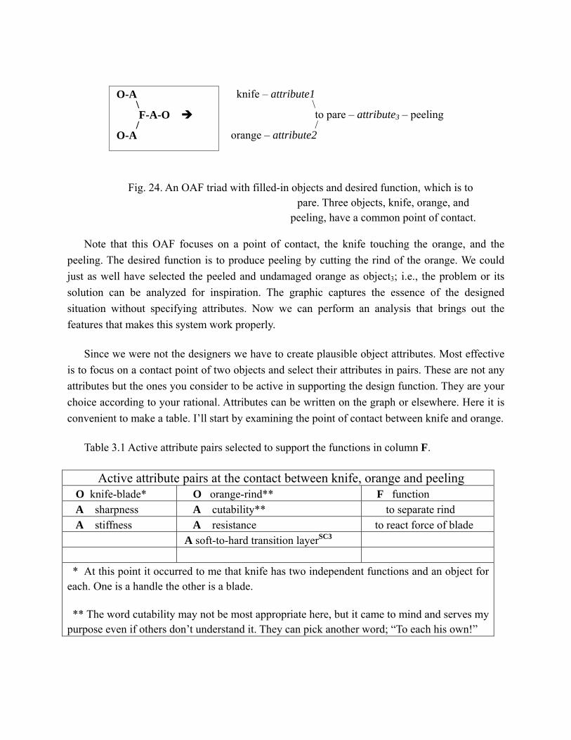
knife – attribute1 \
to pare – attribute3 – peeling /
orange – attribute2
O-A \ F-A-O / O-A
A
Fig. 24. An OAF triad with filled-in objects and desired function, which is to pare. Three objects, knife, orange, and
peeling, have a common point of contact.
Note that this OAF focuses on a point of contact, the knife touching the orange, and the peeling. The desired function is to produce peeling by cutting the rind of the orange. We could just as well have selected the peeled and undamaged orange as object3; i.e., the problem or its solution can be analyzed for inspiration. The graphic captures the essence of the designed situation without specifying attributes. Now we can perform an analysis that brings out the features that makes this system work properly.
Since we were not the designers we have to create plausible object attributes. Most effective is to focus on a contact point of two objects and select their attributes in pairs. These are not any attributes but the ones you consider to be active in supporting the design function. They are your choice according to your rational. Attributes can be written on the graph or elsewhere. Here it is convenient to make a table. I’ll start by examining the point of contact between knife and orange.
Table 3.1 Active attribute pairs selected to support the functions in column F.
ctive attribute pairs at the contact between knife, orange and peeling O knife-blade* O orange-rind** F function A sharpness A cutability** to separate rind A stiffness A resistance to react force of blade
A soft-to-hard transition layerSC3
*
**
At this point it occurred to me that knife has two independent functions and an object for each. One is a handle the other is a blade.
The word cutability may not be most appropriate here, but it came to mind and serves my purpose even if others don’t understand it. They can pick another word; “To each his own!”

4. SI2: An interesting strategy; find attributes of blade and rind that enables blade to cut rind but not pulp. Therein is a conflict. Blade needs to distinguish rind from pulp while cutting
5: SC3: Give pith a hard but thin coat that resists blade on exiting rind. This is an opportunity for invention in bioengineering. Find a gene that determines the toughness of the membrane separating pith from rind. To be discussed with a bioengineer.
We could treat the bioengineering problem using USIT. It could be based on molecular analysis of DNA to find genes that control the interface cell tissue between rind and pith of an orange, which might turn out to be similar in other fruits. Several useful attributes of modified connecting tissue might be available. We could talk with a chemist as well. Having fundamental research in surface physics as my background, I like concepts like this that offer new ideas for research.
Note that we have found several ideas without finishing the OAF heuristic. And we haven’t used the hands or juice in the problem sketch. We have found a more generic term for paring, namely separation, and for the sketch, removal of confusing fingers. This is an opportunity to make a simple iteration in the problem statement/sketch.
Problem statement: 1st iteration.
Separating orange rind from orange pith using a blade produces a non-uniform thickness peeling resulting from cuts made too deep into the pith.
Fig. 25. Sketch of orange, pith, peeling, and blade for the 1st problem statement iteration.
Making the simple change in problem statement, from paring to separation, brought a strategic idea to mind. Without some research, I can’t evaluate the plausibility of this idea, but I’ll record it for future thought.
orange
pithpeeling
blade (no handle)

SI2 Inject something between the rind and the pith that would separate them or loosen a local region.
Whoops! I think I’ve gone astray of the original problem. Our company doesn’t make oranges, it needs to improve its knife product. Perhaps it might help to analyze the blade’s edge specifically by using a simplified sketch of its point of contact.
blade rind pulp
Fig. 26. Point of contact between blade and rind.
This simplified sketch brought my attention the narrow region of rind separating the edge of the blade from the pulp.
SC4: Widen the upper part of the blade with an adjustable-height shoulder that limits the penetration of the blade (double arrow in Fig. 27). Design its penetration to be slightly smaller than the average rind thickness of oranges. Then make spiral cuts on the rind, or crisscrossing circles, or spirals. The resulting strips or tiles can then be picked and pulled loose using fingernails.
F
blade shoulder rind membrane pith
ig. 27. Extension of Fig. 26 with a shoulder added to the blade
SC5: Mount one end of the blade on a pivot in a handle. Mount a spring between the blade and its handle with adjustable tensile or compressive reaction, depending on the direction of force to be reacted. Specific details are to be determined in engineering.

pith rind spring pivot knife hand
Fig. 28. Knife with rotatable blade that is spring-loaded to lock/unlock.
As knife blade penetrates deeper into the rind, the rind becomes less rigid because the bounding region of the cut becomes softer in the underlying pith. A sensor in the blade senses the weakening force of reaction created by the decreasing stress in the rind. A display in the knife handle displays a warning signal of depth of cut. Visual feedback then takes over and the muscle reaction makes appropriate change in pressure on the knife.
SC6. Mount a stress sensor and display in the knife.
SC7. This idea leads to the obvious option of using feedback control for an electronic, automatic peeler.
Filters Note that the problem could have been stated in a form like this: ‘Develop (fill in blank) orange peeler’, where the blank might be filled in with ‘a better’, ‘a more efficient’, ‘a cheaper’, etc. Those examples, and others of their ilk, are filters – to be applied after innovative thinking is completed. I suspect that my unconscious steered my conscious around that diversion.
This four-word problem statement is simple and easy to understand. Simplicity is the best beginning to a real USIT problem statement. However, we could have put more information into it including unwanted symptoms, root causes, graphics, examples of known solutions, and even some desired behavior of a more desirable peeler. I recommend selecting the simpler statement. Whatever we start with will be modified several times as we proceed.
Heuristic: Minimize the number of objects in a problem statement by addressing a single problem. The brain cannot solve two problems at the same time.
Having solved the first problem, writing a problem statement, we now face what is often the most difficult step in problem solving; i.e., where to begin? USIT offers a powerful graphic heuristic based on objects, attributes, and the functions they support. As we adapt this heuristic to

the peeler problem we immediately begin an analysis of the problem. The heuristic is illustrated in the following graphic.
On the left-hand side are two interacting objects. Metaphorically speaking they are in contact via one active attribute of each object. This contact causes an unwanted effect that is evinced through an active attribute of another object (a third object or one or both of the original two).
Here we start down another thought path where solution concepts can occur at any time. It begins as we try to fill in concrete examples of the OAFs in the peeler problem.
Heuristic
blade – sharpness \ to cut – separation– rind / rind – toughness
Fig. 29. A sharp blade contacts a tough rind cutting a separation in the rind.
Clearly, we can start with orange and peeler as two interacting objects. Furthermore we can build the rest of this diagram using a known solution as a model. I’m thinking of a hand-held knife as the peeler.
handle blade rind pith
Fig. 30. Sharp blade in contact with rind causes a separation in rind when orange is rotated or blade dragged across rind in a slicing motion.
Understand that this diagram is a tool for trying any variety of OAFs that come to mind in formulating the problem and searching solution concepts. Follow the first ideas to come to mind.

handle handle-mount (orange) hub (white) cutting wheel
Fig. 31. Cutting wheel with smaller diameter hub that limits the depth of cut.
cam
depth of cam depth of pith
Fig. 32 Wheel cutter with cam hub that allows adjustable hub-offset from the axis of rotation. With detents (not shown) incremental offsets can be held in place. This sketch appears a little oblique, but it is the same planar view as in Fig. 31 with the circular hub now drawn as an ellipse.
At this point the diagram looks like …
orange – (attribute)
\ to shave – oval shape – cam /
knife – sharp edge
Fig. 33. Attributes of two objects that touch the orange, but not physically at the same point, cam and knife. This illustrates the simplification of using a metaphorical point of contact.
In a more detailed procedure we would list other options for the OAFs in order to force us to make a rational decision of where to place them and why (provocative thinking). This process gradually unfolds a plausible understanding of the original system design and plausible understanding of cause and effect of our problem. Furthermore, it gives us focus on one point of contact.

Continuing our OAF diagram, I see the orange’s attributes, in this situation, as a hard spherical object having a protective layer. The sphere and layer have different consistencies of strength, shape, resistance to cutting, and others. Here’s a next stage of the OAF:
Fi
orange – cuttable layer \ to shave – imperfect – peel / knife – sharp edge
g. 34. Repeat of Fig. 33 with filled in attributes, cuttable layer, sharp edge, and imperfect.
I decided to put the unwanted effect in the attribute of the third object, the orange peel. (This is my analysis. You can put your own unwanted effect where you please. What follows may differ. No two minds think the same way.) By imperfect peel I mean an unclean shaving having chunks of orange stuck to it.
Once we have our ideas we are ready for filtering them vis-à-vis practicality, cost, fabrication, interest, business plan, and on and on. At this junction we are finished with USIT. We are ready for engineering scale up, proof of concept, etc. Hence, USIT is the pre-engineering stage of problem solving. We don’t need equations or specifications in this stage. Of course we invoke USIT strategies again and again as new problems are encountered.
In that last sentence we find a motivation for having simple and effective problem solving methodologies. We face the tedium of drawing tree-like structures and various graphs in problem solving until we master them. Gradually they seem to be absorbed into our unconscious. There they perform sight unseen, so to speak. Now we are prepared to combine all of structure into one simple three-element diagram.
The three-element diagram is simply O•A•F, and its combinations – as one’s imagination discovers. Into O•A•F is packed a single problem. Out of it we discover multiple solution concepts with the aid of an endless variety of heuristics (tricks for sparking innovative thinking). Heuristics are the techniques we use to solve problems. We learn them in school, we invent them, and we encounter them on the job – a never-ending growth process.
There is one more idea to add to our list. This one came to mind when discussing a second degree of freedom for the blade; namely, the range of tilt angle.

SC8. Hold the blade roughly perpendicular to the orange and, using a motor, have it vibrate. This would produce an abrasive scrubbing action and provide more control on cutting rate.
We found 8 solution concepts (and several ideas not numbered) using 10 sketches (graphic heuristics), and 6 verbal heuristics, 5 as variations on the OAF diagram and 1 being the problem statement. The most productive heuristic, in this brief example was to make sketches. Not bad for a few minutes of work.

▪ 2.2 Abbreviations
ASIT advanced systematic inventive thinking; C conscious; C/E cause/effect; CG center of gravity; CWD closed world diagram; LB left-brain hemisphere; SBS structured inventive thinking; OAF objects, attributes, and functions, also single symbol comprising USIT heuristics; RB right-brain hemisphere; RC root cause; SC subconscious; SIT systematic inventive thinking; UC unconscious, USIT unified structured inventive thinking; indicate where an ideas occurred during analysis; possible invention or other significance;
▪ Reference
Dehaene, Stanislas, Consciousness and the Brain: Deciphering How the Brain Codes Our Thoughts, Viking Books, 2014.
Edwards, B. Drawing on the Right Side of the Brain. Los Angeles; J. P. Tarcher, 1979.
Finke, R. A., Ward, T. B., and Smith, S. M., Creative Cognition, Theory Research, and Applications, The MIT Press, 1996.
Sickafus, E. N. (1997). Unified Structured Inventive Thinking – How to Invent. ISBN 0-9659435-0-X, Ntelleck, LLC
Sickafus, Ed. N. (2006). Heuristic Innovation, Engaging Both Brain Hemispheres in Rapidly Solving Technical Problems for Multiple Solution Concepts. Retrieved from www.u-sit.net.
To be creat ive U-SIT and THINK.