a centralized processing, distributed i/o motor …cs.jhu.edu/~pault/wiki/images/3/39/qual2010.pdfa...
TRANSCRIPT

A Centralized Processing, Distributed I/O MotorController Based on IEEE 1394 for the Snake Robot
Paul Thienphrapa
Department of Computer ScienceJohns Hopkins University3400 North Charles Street
Baltimore, MD 21218
May 14, 2010
This project fulfills a requirement for the Ph.D. degree.
Advised By: Peter Kazanzides
Advisor Signature and Date:

Abstract
Research in surgical robots often calls for multi-axis motor controllers and other I/O hard-ware for interfacing various devices with computers. To facilitate convenient prototyping ofrobots with large numbers of axes and I/O lines, it would be beneficial to have controllersthat scale well in this regard. We would like to incorporate additional components to asystem without necessitating an unwieldy increase in I/O devices, nor introduce too manydisjoint software interfaces and environments. High speed serial buses such as IEEE 1394(FireWire) make it possible to consolidate multiple data streams into a single cable, and con-temporary computers have the computational resources to process such dense data streams.These factors motivate a centralized processing, distributed I/O control architecture, whichis particularly advantageous for education and research. This paper documents the design,implementation, and testing of a motor controller and its associated API using this designapproach. A real-time controller for the Johns Hopkins University Snake Robot, a novel,miniature, and dexterous surgical manipulator with many degrees of freedom, is developedthat combines previous experience and the aforementioned motivations with readily availablebut powerful new technologies.

Contents
1 Introduction 5
1.1 Background . . . . . . . . . . . . . . . . . . . . . . . . . . . . . . . . . . . . 5
1.2 Snake Robot . . . . . . . . . . . . . . . . . . . . . . . . . . . . . . . . . . . . 6
1.3 Scalable Motor Controller for the Snake Robot . . . . . . . . . . . . . . . . . 7
1.4 Motivations . . . . . . . . . . . . . . . . . . . . . . . . . . . . . . . . . . . . 9
1.5 Proposed Solution . . . . . . . . . . . . . . . . . . . . . . . . . . . . . . . . . 10
2 Related Work 11
2.1 Ethernet-Based Alternatives to IEEE 1394 . . . . . . . . . . . . . . . . . . . 12
2.2 Other Alternatives to IEEE 1394 . . . . . . . . . . . . . . . . . . . . . . . . 12
3 Selection of IEEE 1394 12
4 Centralized Processing, Distributed I/O 14
5 Hardware Design 15
5.1 System Overview . . . . . . . . . . . . . . . . . . . . . . . . . . . . . . . . . 15
5.2 Amplifier Section . . . . . . . . . . . . . . . . . . . . . . . . . . . . . . . . . 16
5.3 Digital Section . . . . . . . . . . . . . . . . . . . . . . . . . . . . . . . . . . 18
5.4 Implementation . . . . . . . . . . . . . . . . . . . . . . . . . . . . . . . . . . 20
6 Firmware Section (FPGA) 21
6.1 IEEE 1394 State Machine . . . . . . . . . . . . . . . . . . . . . . . . . . . . 21
6.2 Channel Modules . . . . . . . . . . . . . . . . . . . . . . . . . . . . . . . . . 23
6.3 Global I/O Module . . . . . . . . . . . . . . . . . . . . . . . . . . . . . . . . 24
6.4 Address Maps . . . . . . . . . . . . . . . . . . . . . . . . . . . . . . . . . . . 24
7 Software API 25
7.1 Block Diagram . . . . . . . . . . . . . . . . . . . . . . . . . . . . . . . . . . 25
1

7.2 Application Programming Interface . . . . . . . . . . . . . . . . . . . . . . . 26
7.3 Demonstration . . . . . . . . . . . . . . . . . . . . . . . . . . . . . . . . . . 30
8 Experiments 31
8.1 Setup and Verification . . . . . . . . . . . . . . . . . . . . . . . . . . . . . . 31
8.2 Quadlet Transfers . . . . . . . . . . . . . . . . . . . . . . . . . . . . . . . . . 31
8.3 Block Transfers . . . . . . . . . . . . . . . . . . . . . . . . . . . . . . . . . . 32
8.4 Discussion . . . . . . . . . . . . . . . . . . . . . . . . . . . . . . . . . . . . . 33
9 Ongoing and Future Work 34
10 Conclusions 35
11 Acknowledgments 36
2

List of Figures
1 A minimally invasive surgery setup . . . . . . . . . . . . . . . . . . . . . . . 5
2 Snake Robot prototype . . . . . . . . . . . . . . . . . . . . . . . . . . . . . . 6
3 Anatomy of a snake-like unit (left) and photo (right) . . . . . . . . . . . . . 7
4 Snake Robot actuation unit . . . . . . . . . . . . . . . . . . . . . . . . . . . 8
5 Original ISA-based Snake Robot motor controller . . . . . . . . . . . . . . . 9
6 Original Snake Robot cabling with centralized I/O . . . . . . . . . . . . . . . 10
7 Robot control hierarchy . . . . . . . . . . . . . . . . . . . . . . . . . . . . . 14
8 Centralized processing, distributed I/O architecture . . . . . . . . . . . . . . 15
9 Conceptual overview of the control system . . . . . . . . . . . . . . . . . . . 16
10 Photo of the completed controller hardware . . . . . . . . . . . . . . . . . . 17
11 Block diagram of the amplifier section (FPGA and PHY chip also shown) . . 18
12 Photo of the completed amplifier section . . . . . . . . . . . . . . . . . . . . 18
13 Block diagram of a node . . . . . . . . . . . . . . . . . . . . . . . . . . . . . 19
14 Altera UP3 FPGA development board . . . . . . . . . . . . . . . . . . . . . 20
15 Custom daughterboard containing IEEE 1394 physical layer chip . . . . . . . 21
16 FPGA structure and operation . . . . . . . . . . . . . . . . . . . . . . . . . 22
17 Block read (left) and write (right) packet formats as interpreted by the FPGA 26
18 General robot control API . . . . . . . . . . . . . . . . . . . . . . . . . . . . 28
19 Test and configuration program . . . . . . . . . . . . . . . . . . . . . . . . . 30
20 IEEE 1394 quadlet read and write transaction times . . . . . . . . . . . . . . 32
21 IEEE 1394 transaction times vs. block size . . . . . . . . . . . . . . . . . . . 33
3
List of Tables
1 Device map of quadlet transaction address field . . . . . . . . . . . . . . . . 25
2 Status code definition . . . . . . . . . . . . . . . . . . . . . . . . . . . . . . . 29
4
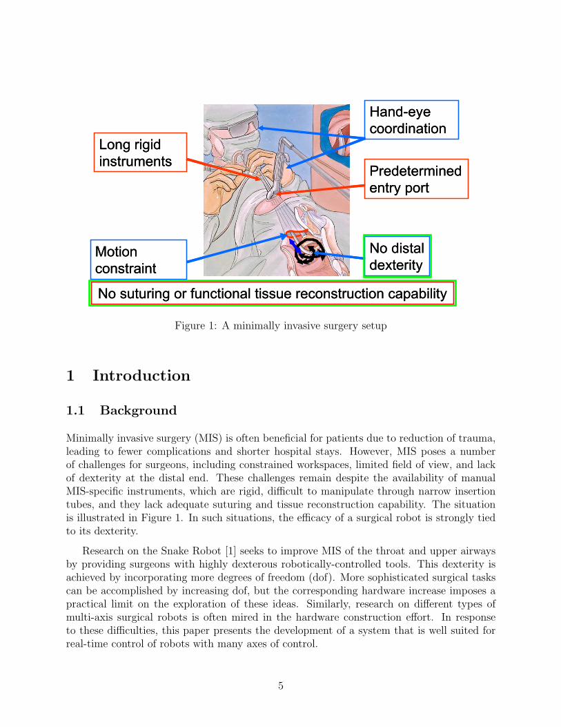
Figure 1: A minimally invasive surgery setup
1 Introduction
1.1 Background
Minimally invasive surgery (MIS) is often beneficial for patients due to reduction of trauma,leading to fewer complications and shorter hospital stays. However, MIS poses a numberof challenges for surgeons, including constrained workspaces, limited field of view, and lackof dexterity at the distal end. These challenges remain despite the availability of manualMIS-specific instruments, which are rigid, difficult to manipulate through narrow insertiontubes, and they lack adequate suturing and tissue reconstruction capability. The situationis illustrated in Figure 1. In such situations, the efficacy of a surgical robot is strongly tiedto its dexterity.
Research on the Snake Robot [1] seeks to improve MIS of the throat and upper airwaysby providing surgeons with highly dexterous robotically-controlled tools. This dexterity isachieved by incorporating more degrees of freedom (dof). More sophisticated surgical taskscan be accomplished by increasing dof, but the corresponding hardware increase imposes apractical limit on the exploration of these ideas. Similarly, research on different types ofmulti-axis surgical robots is often mired in the hardware construction effort. In responseto these difficulties, this paper presents the development of a system that is well suited forreal-time control of robots with many axes of control.
5

Figure 2: Snake Robot prototype
1.2 Snake Robot
A unique design targeted for MIS of the upper airways, the Snake Robot addresses theseissues by introducing a small, dexterous end effector that can be teleoperated. To avoidobscuring the work area, the end effector is attached to its actuators via a hollow, narrow,meter-long shaft containing its wires, and appears at the distal end of a laryngoscope; thisshaft is also teleoperable, as described below. Figure 2 depicts the configuration.
The Snake Robot is an eight-degree of freedom (dof) (11-actuator) manipulator. MultipleSnake Robots may be used for surgical tasks including bimanual suturing, suction, and cam-era placement. The dexterous end effector consists of two snake-like units (SLUs) connectedin series; each SLU is constructed using four superelastic NiTi tubes. The anatomy of anSLU is shown in Figure 3. The center tube, i.e. the primary backbone, is surrounded by thethree other tubes, the secondary backbones, at equally-spaced radial and angular distances.These four backbones are fixed to the end disc, but only the primary (central) backbone isfixed to the base disc; all backbones are free to glide through holes in the equally-spacedintermediate spacer discs.
6
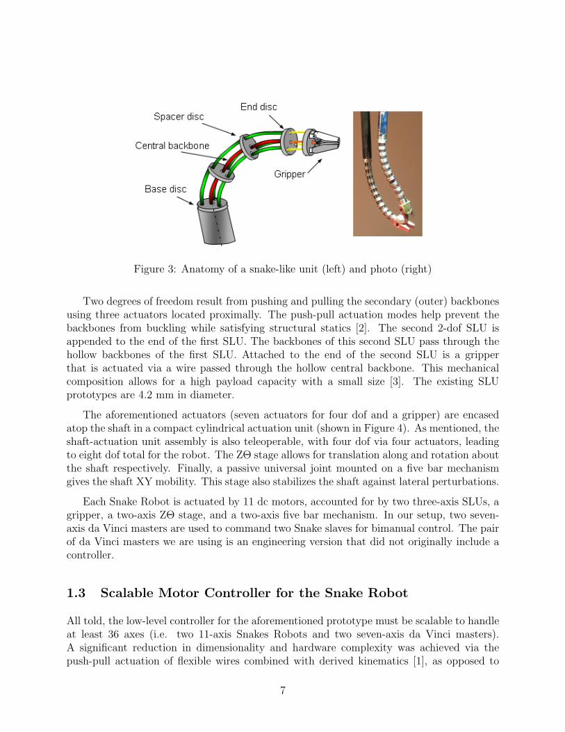
Figure 3: Anatomy of a snake-like unit (left) and photo (right)
Two degrees of freedom result from pushing and pulling the secondary (outer) backbonesusing three actuators located proximally. The push-pull actuation modes help prevent thebackbones from buckling while satisfying structural statics [2]. The second 2-dof SLU isappended to the end of the first SLU. The backbones of this second SLU pass through thehollow backbones of the first SLU. Attached to the end of the second SLU is a gripperthat is actuated via a wire passed through the hollow central backbone. This mechanicalcomposition allows for a high payload capacity with a small size [3]. The existing SLUprototypes are 4.2 mm in diameter.
The aforementioned actuators (seven actuators for four dof and a gripper) are encasedatop the shaft in a compact cylindrical actuation unit (shown in Figure 4). As mentioned, theshaft-actuation unit assembly is also teleoperable, with four dof via four actuators, leadingto eight dof total for the robot. The ZΘ stage allows for translation along and rotation aboutthe shaft respectively. Finally, a passive universal joint mounted on a five bar mechanismgives the shaft XY mobility. This stage also stabilizes the shaft against lateral perturbations.
Each Snake Robot is actuated by 11 dc motors, accounted for by two three-axis SLUs, agripper, a two-axis ZΘ stage, and a two-axis five bar mechanism. In our setup, two seven-axis da Vinci masters are used to command two Snake slaves for bimanual control. The pairof da Vinci masters we are using is an engineering version that did not originally include acontroller.
1.3 Scalable Motor Controller for the Snake Robot
All told, the low-level controller for the aforementioned prototype must be scalable to handleat least 36 axes (i.e. two 11-axis Snakes Robots and two seven-axis da Vinci masters).A significant reduction in dimensionality and hardware complexity was achieved via thepush-pull actuation of flexible wires combined with derived kinematics [1], as opposed to
7

Figure 4: Snake Robot actuation unit
actuation of several precision joints. Nevertheless, the number of control axes for the SnakeRobot remains considerable, as does its associated cabling. One can envision the increasesin both as systems are devised for more sophisticated surgical tasks. By distributing I/Oover an IEEE 1394 (FireWire) bus to nodes with low-latency field-programmable gate arrays(FPGAs), and by centralizing processing, the control system hardware proposed here aimsto mitigate the potential problems in robot mobility and reliability that arise with increasingstructural complexity.
The efforts presented here and in [18, 19, 21] originate in part from the need to improvethe old multi-axis controller (Figure 5) [2] of the Snake Robot and replicate the controller forother research projects. The old controller utilizes a centralized I/O arrangement, wherebycommand and feedback signals are transmitted in raw analog form over long cables runningbetween the robot and the computer. The I/O devices reside on custom circuit boards,which in turn are directly attached to the computer via its ISA bus. Though the design isconceptually straightforward, the cumbersome wiring associated with it introduces compli-cations such as noise, cable drag, reduced reliability, and greater construction effort. Thedebug space is vast as there are many candidates for connectivity problems, so this approachlimits the ability to develop increasingly dexterous surgical robots. Figure 6 is a photo ofthe Snake Robot that captures this scenario.
8

Figure 5: Original ISA-based Snake Robot motor controller
1.4 Motivations
The long term benefits of developing a control system using IEEE 1394 are multifold. Thehigh speed serial bus encourages the distributed I/O and centralized processing architecture.One advantage of this approach is that the I/O processing logic is simple and requires littlemaintenance. Signal integrity is improved because digitization occurs near the actuators,reducing the potential for noise corruption.
Cable complexity is greatly reduced because distributed I/O hardware is accessed througha serial link. This has several benefits in educational and research environments. Lesseffort is required in creating cables and breakout boards when new robots are developed.Since I/O hardware is replicated, standard wiring conventions are enforced. Robustnessis improved overall because there is less potential for wiring problems and less cable dragaffecting mobility.
Parallel buses limit the number of I/O channels that can be connected to one computer.Using the old ISA-based controller as an example, an industrial-grade computer can reliablydrive four ISA cards, and the number of channels per card is constrained to four by physicalsize. As a result, a teleoperated dexterous robot system may need multiple computers torun.
In contrast, IEEE 1394 allows for centralized processing of a large number of multiplexedchannels on a single centralized computer, so low-latency local data exchange can be usedinstead of network communication. The integration allows for a familiar software develop-ment environment and a standard API; this alleviates researchers and programmers from
9

Figure 6: Original Snake Robot cabling with centralized I/O
learning the idiosyncrasies of individual embedded microcontrollers, so they can instead fo-cus on higher-level tasks. Furthermore, this architecture can more readily harness the powerof high performance computers.
This work is also intended to facilitate further research by providing a generic inter-face and scalable mechanism for fine-grain real-time control. Such a custom solution wasnecessary for servoing the low power dc motors of the Snake Robot [2] because an ade-quate commercial solution was not available. The solution allows for flexible customizationof parameters, investigation of complex control laws, and high-density distributed I/O. Itis designed to ease the development of dexterous surgical robots from both hardware andsoftware perspectives.
1.5 Proposed Solution
Historically, the architecture of robot controllers has been dictated by technology constraints.When computers and networks were slow, it was necessary to logically distribute the compu-tation but to physically centralize both the computation and I/O. This is represented by acontroller comprised of a large rack of embedded processors, with cables to all robot sensorsand actuators. As technology improved, it became feasible to distribute both computation
10

and I/O, as illustrated by systems that use a field bus to connect a central controller tolow-level processors embedded near or within the robot.
A traditional solution to robot control comprises multiple joint-level control boardshoused in a central computer through a high-performance parallel bus, such as ISA, Q-Bus, Multibus, or VME. Under this approach, however, the requisite cabling and controlprocessing for surgical robots can become unwieldy as dexterity is increased, due to theincreasing degrees of freedom. This can be a prohibitive factor for medical robot research,and furthermore does not extend well to increases in the number of joints.
Motivated by the dexterous Snake Robot, we have developed a real-time low-level con-trol system that takes advantage of a high-speed serial bus, IEEE 1394, and capitalizes onthe processing power of contemporary computers. Using a low-latency field-programmablegate array as the link between the computer and a possibly large quantity of I/O devices,all processing tasks are performed on a single computer while I/O tasks are distributed.Centralized processing simplifies software development, and a standard API is developed toaugment this feature. Meanwhile, distributed I/O helps cleanly confine most wires to lo-cal joint sites thereby substantially reducing complex cabling, a high-risk source of failures.This architecture enables the exploration of complex surgical systems and technologies byallowing for more agility, reliability, and scalability.
We have thus far equated the dexterity of a robot with its degrees of freedom. Though thisis not always the case, the level of scalability being sought ultimately requires a proportionalincrease in degrees of freedom. From the perspective of the low-level controller, there is littledistinction between the concepts degrees of freedom, joints, actuators, axes, and channelsbecause they can all be decomposed into I/O signals. Thus in this paper we sometimes usethese terms interchangeably.
2 Related Work
Though based on IEEE 1394, the works of [6] and [12] focus on real-time control bandwidth,and not on the physical benefits of distributed I/O and centralized processing. The differ-ences manifest in their use of IEEE 1394 as a link to an onboard computer, contrasting withour use of compact custom electronics. Our work is most similar to that of [16], where customFPGA-based I/O boards communicate with the computer over IEEE 1394. The bandwidthwas sufficient for at least six (possibly 12) dof to be updated at 1 kHz, with unit delaylatency. On the other hand, this study emphasizes the physical benefits of the architecture,performance, and scalability. Ref [17] notes that using IEEE 1394 for high bandwidth PETscan data acquisition is viable due to the availability of powerful commodity computers. Weagree in principle, though our respective applications are fundamentally different.
11

2.1 Ethernet-Based Alternatives to IEEE 1394
Fair bus access is incorporated into IEEE 1394 hardware; bus arbitration in Ethernet isnondeterministic, but kilohertz-range motor control is achievable on isolated networks withsoftware modifications [14, 15]. Several Ethernet variations have been developed that makethe medium very promising. Powerlink [22] employs a bus manager that schedules 200-µscycles of isochronous and asynchronous phases. SERCOS approached a communication bot-tleneck in [9] with increasing axes and cycle rates, but its recent combination with Ethernet(SERCOS-III) has endowed it with the ability to update 70 axes every 250 µs.
A relative newcomer, EtherCAT [23] is an attractive protocol in which the nodes forwardand append packets on-the-fly using dedicated hardware and software, resulting in the abilityto communicate with 100 axes in 100 µs; [8] is an example showing its potential.
2.2 Other Alternatives to IEEE 1394
Many of the themes highlighted in this paper, including distributed I/O, centralized com-puting, scalability, and form factor, echo those of [10], which documents the MIRO surgicalrobot developed by the German Aerospace Center (DLR). Scalability in the MIRO robotis aided by the use of SpaceWire, a 1 GB/s full duplex serial link with latency less than20 µs. Whereas SpaceWire has been developed by major international space agencies forspace-borne systems, we prefer IEEE 1394 as it is a more accessible protocol for research,and its performance is more than adequate for demonstrating our claims. We are particu-larly more interested in the software-induced latency and overcoming this latency to enhancescalability.
PCI Express is a fairly new serial interface designed to replace computer expansion buses;a cable-based standard was not fully established at the time of the designs presented in thispaper. PCI Express supports real-time applications such as the industrial control examplein [11]. High data rates are readily available with USB, but its reliance on the host processorfor bus level tasks compromises its scalability in real-time control. Conversely, IEEE 1394self-manages the bus at the physical layer. The Controller Area Network (CAN) [24] bus iswell-suited for real-time control and has been widely used, but its bandwidth is limited to1 Mbps. Though not a serial bus, CompactPCI is an industrial backplane interface capableof 132 MB/s throughputs, used notably in space systems by NASA in transitioning fromVMEbus [20].
3 Selection of IEEE 1394
The desire to perform real-time robot control, at frequencies of 1-10 kHz, over a serialnetwork leads to several key requirements. First, we note that data packets are relatively
12
small. For example, closed-loop control of a robot joint can be accomplished with as littleas one feedback position (e.g., from a pot or encoder) and one control signal (e.g., voltageor current to apply to the motor). A more generous setup may contain a few feedbacksignals (e.g., position, velocity, motor current, amplifier status) and a few control signals(e.g., voltage and current limit). Even if 32-bit values are used for many of these, a typicaldata packet (read or write) would be on the order of 100 bytes. Thus, a six-joint robot wouldrequire about 1200 bytes (6*200); at a control frequency of 10 kHz, this would require a busbandwidth of 12 MBps, or approximately 100 Mbps. This is not difficult to achieve withmodern high-speed serial networks, such as IEEE 1394 (up to 400 or 800 Mbps for 1394a or1394b, respectively), USB 2.0 (up to 480 Mbps) or Ethernet (10, 100, or 1000 Mbps).
A more critical performance metric is the latency of the data transfers because it intro-duces a time delay in the control computations, which compromises performance and canlead to instability. Latency is primarily determined by overhead in the protocol and thesoftware drivers. Based on our review of specifications and published reports, we concludedthat IEEE 1394 should provide the lowest latency, especially when used with a real-timeoperating system. The protocol supports real-time communication with guaranteed 8 kHz(125 µs) bus cycles in isochronous mode, though asynchronous mode is used instead as itallows for even faster access rates. It is an effective solution for real-time control, as shownin [6, 12], and by its use in fly-by-wire systems [7]. In the present work, the minimum re-quirement is to support all of the Snake Robot I/O lines with a system bandwidth of onekilohertz.
Another important requirement is the ability to daisy-chain nodes. For example, if amulti-axis robot contains embedded I/O boards, daisy-chaining allows just a single networkcable to be connected to the robot—this cable connects to the first I/O board, which thenconnects (daisy-chains) to the second board, and so on. This allows a significant cablingreduction compared to connecting a separate network cable to each board (i.e., a star topol-ogy). Physically, all of the considered serial networks (except the outdated 10 Mbit Ethernetwith coaxial cable) utilize point-to-point links but provide daisy-chaining solutions. IEEE1394 provides an especially attractive and inexpensive solution by providing repeaters at thephysical layer. In contrast, USB requires a hub (with associated cost and complexity) andEthernet typically uses high-speed switches.
A potential drawback of IEEE 1394 is the lack of high-flexibility cables for installationwithin the moving structure of a robot arm. In our application, this is not a serious limi-tation because medical robots move slowly and infrequently compared to industrial robots.Currently, the Ethernet variations described above provide better cabling options. Ether-net, as well as USB, also have the advantage of market dominance. Although we concludedthat standard Ethernet was not ideal for real-time control, we did not consider the many“real-time” Ethernet variations that have been created. Many of these Ethernet variationsalso support daisy-chaining without the use of switches. Given the aforementioned consid-erations, we ultimately selected IEEE 1394 while noting that it is not necessarily the singlebest choice. We furthermore chose 1394a, rather than the faster 1394b, because it provided
13

ample bandwidth and the lower signal frequencies simplified the hardware design.
At the time of our initial evaluation (ca. 2006), we did not consider PCI Express becauseit was limited to backplanes and circuit boards. With the recent introduction of a cable-based standard, PCI Express appears to be an attractive alternative because it would notrequire protocol conversion between the motherboard and peripheral devices.
4 Centralized Processing, Distributed I/O
Robot systems are concurrent by nature: multiple joints must be controlled simultaneously,and there is often a hierarchy of control strategies. A typical robot controller (Figure 7)contains “loops” for servo control, supervisory (e.g., trajectory) control, and the application.In many cases, the servo loop is distributed among multiple joint-level microprocessors.
Figure 7: Robot control hierarchy
In the early days of robotics, controllers consisted of a central computer with multiplejoint-level control boards on a parallel bus, such as ISA, Q-Bus, Multibus, or VME; this wasnecessary for performance reasons alone. Although the central computer usually containedmultiple processors (e.g. joint-level control boards), this architecture can be characterizedas centralized processing and I/O.
With the emergence of high-speed serial networks, such as CAN, Ethernet, USB, andIEEE 1394, it became possible to physically distribute the joint controller boards and asso-ciated power amplifiers. By placing these components inside the robot arm, or at its base,significant reductions in cabling could be achieved. In particular, the thick cables containingmultiple wires for motor power and sensor feedback could be replaced by thin network andpower cables. These types of systems can be characterized as distributed processing andI/O.
14

Given the recent advances in processor performance, especially the move to multi-corearchitectures, coupled with the extraordinarily high data rates of modern serial networks,we advocate a new approach for robot control: centralized processing and distributed I/O(Figure 8). This can be achieved by replacing the microprocessors with FPGAs that providedirect, low-latency, interfaces between the high-speed serial network and the I/O hardware.As discussed earlier, this preserves the advantages of reduced cabling, while allowing allsoftware to be implemented on a single high-performance computer that contains a familiarsoftware development environment, freeing developers from having to learn the idiosyncrasiesof the various embedded microprocessors. Another key factor in realizing real-time central-ized processing is the availability of low-cost real-time operating systems, such as those basedon Linux.
Figure 8: Centralized processing, distributed I/O architecture
A key motivation for building a novel control system is to ease the process of develop-ing multi-axis robots in terms of both hardware and software construction. The hardwareprovides fine-grain real-time control over a large number of motors, with I/O conversiontasks delegated to the actuator sites. Using IEEE 1394, the hardware confines raw analogsignals to those sites and multiplexes the digital data for all channels over a high speed serialconnection to a single computer.
5 Hardware Design
5.1 System Overview
Figure 9 provides an overview of the control system, with I/O conversion distributed awayfrom the computer to the actuator sites. Each node on the bus contains multiple channels(or axes of control, and described as the amplifier section below). Nodes can be added tothe system by daisy-chaining or by direct connection to the computer—each node containstwo IEEE 1394 ports for this reason. The bus is attached to a real-time computer thatreads feedback signals from the channels, generates actuation commands, and writes themto their respective channels. The completed controller hardware for the Snake Robot isshown in the photo (Figure 10). Note that this particular hardware has been designed tophysically integrate on the top of the Snake Robot actuation unit; other form factors havebeen developed for general use.
15

Figure 9: Conceptual overview of the control system
5.2 Amplifier Section
Depicted in Figures 11 and 12, the amplifier section contains the power amplification andI/O components required to control one dc motor. It is referred to as an I/O channel fromthe perspective of the digital section, which is detailed in the next subsection. Among thevarious I/O signals, one is used to enable or disable the motor, and one used to signal an opamp fault, e.g. due to overheating. The power amplifier is implemented as bridge amplifier[28]; two op amp devices are configured in such a way as to require only one motor powersupply. The midpoint voltage of this supply, denoted VM/2, is used as the zero level of themotor. That is, to stop the motor, both the positive and negative terminals of the motorare set to VM/2. Depending on the desired magnitude and direction of rotation, the motorcommand sets the master op amp voltage to some value above or below VM/2. In turn,the slave op amp voltage is driven an equal magnitude but opposite direction away fromVM/2, simulating the presence of a positive and negative voltage source. Extensive testshave shown some asymmetric behavior and saturation at the supply voltage rails [26], butwe expect to overcome this issue in the closed PID loop.
Other fundamental I/O components include an analog-to-digital converter (ADC), adigital-to-analog converter (DAC), and a digital potentiometer. The dual-channel ADCdigitizes analog feedback, namely the potentiometer voltage that measures absolute actu-ator position, and the motor current, which can be used to determine torque. The DAC
16

Figure 10: Photo of the completed controller hardware
provides voltage commands for the motor speed, as well as the motor current limit signal.The board outputs incremental encoder pulses, properly level translated to ensure that theFPGA input voltage limit (3.3 V) is satisfied. The FPGA decodes the quadrature encoderpulses to compute motor displacement and velocity measurements.
The digital potentiometer is used to program the gain on motor current feedback from thepower amplifier. The intent is to pretune the gain for a specific motor and store that settingon its nonvolatile, 14-word, 16-bit EEPROM for operational use. Calibration proceduresand measurement results are documented in [26]. In addition to a programmable wiper andEEPROM, the digital potentiometer also contains two programmable digital outputs. Oneof these, labeled O1, is used to select between control modes. Setting this output low selectstorque control, in which case current feedback into the motor amplifier is shut off in orderto maintain constant motor torque. A high setting selects speed control; motor current isfed back into the amplifier to maintain constant speed.
The ability to program the amplifier settings allows for adaptation to other robots withlow-power motors. The hardware modifications required, e.g. changing the value of the motorcurrent sense resistor, are of minimal difficulty and cost. This programmability, combinedwith the current and anticipated need for many such boards, serves as motivation towards acustom solution. The distributed I/O architecture encourages modular one-board-per-motor
17
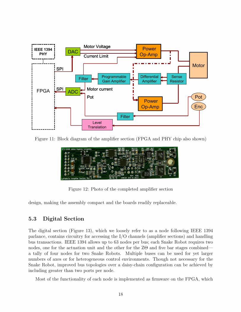
Figure 11: Block diagram of the amplifier section (FPGA and PHY chip also shown)
Figure 12: Photo of the completed amplifier section
design, making the assembly compact and the boards readily replaceable.
5.3 Digital Section
The digital section (Figure 13), which we loosely refer to as a node following IEEE 1394parlance, contains circuitry for accessing the I/O channels (amplifier sections) and handlingbus transactions. IEEE 1394 allows up to 63 nodes per bus; each Snake Robot requires twonodes, one for the actuation unit and the other for the ZΘ and five bar stages combined—a tally of four nodes for two Snake Robots. Multiple buses can be used for yet largernumbers of axes or for heterogeneous control environments. Though not necessary for theSnake Robot, improved bus topologies over a daisy-chain configuration can be achieved byincluding greater than two ports per node.
Most of the functionality of each node is implemented as firmware on the FPGA, which
18

Figure 13: Block diagram of a node
serves as a low-latency interface between the channel I/O ports and the bus. The FPGAreceives packets from the bus, responds to them, and communicates with the I/O devices.The computer accesses channel data through control and data registers on the FPGA. Themaximum number of channels accessible on one node is governed in large part by the charac-teristics of the FPGA, such as the number of logic elements, number of general purpose I/Opins, and speed. This design uses the Altera Cyclone II EP2C8Q208C7N [27], a low-costmodel with 8256 logic elements and 138 I/O pins. It is capable of clock speeds of up to260 MHz, though this depends heavily on firmware complexity. Under our current firmwareimplementation, the Cyclone II is comfortably capable of handling the seven channels ofa Snake Robot actuation unit at about double the required 49.152 MHz clock frequencyand 60% resource utilization. Several I/O pins remained as spares and are routed out toone of several header pins or test points. Nevertheless, more powerful FPGAs are favor-able, and subsequent designs utilize higher-end devices. The FPGA is programmed througha JTAG connector during development, and a separate connector is used for storing com-pleted firmware into a configuration PROM. Specifications allow for these connectors to bemerged; though we did not do this initially due to a conservative design approach, the featureis exploited in our later work.
The Texas Instruments TSB41AB2 is a two-port IEEE 1394a physical layer integratedcircuit that converts between digital data and the analog signals used to convey them athigh speed (400 Mbps) over the bus. The FPGA sends and receives data over the bus byinteracting with this device, specifically via control lines and an eight-bit data bus. Thedevice also generates a 49.152 MHz clock, derived from a 24.576 MHz crystal, which theFPGA uses as its system clock. In this way all communications between the various I/O
19

devices and the physical layer chip are synchronized. Due to the relatively high speeds thatthe device is capable of, careful attention was paid to its layout on the PCB, particularlyaround the impedance-controlled differential analog lines, termination resistors, clock I/Os,and bypass capacitors.
Also included in the digital section is a four-bit rotary switch used to uniquely identify anode to control software. Although nodes are uniquely identified via the IEEE 1394 protocol,the address assignment is dynamic. An array of LEDs is used to indicate the status of eachof the seven amplifiers; a lit LED signifies that the corresponding amplifier is enabled, whilean unlit LED means that the amplifier is disabled, possibly due to assertion of its fault line.
For noise isolation, and to facilitate emergency shutdowns, the motor and digital voltagesare drawn from separate regulated supplies. Power from the bus is not used for these reasons,as well as to simplify the development effort, but future designs may draw bus power.
5.4 Implementation
We used an FPGA development board (Altera UP3, Figure 14) for the first prototype toreduce our development risk. Realistically, we expected that our system would not workthe first time we connected a computer to the prototype node. The development boardeliminated the possibility that we did not properly design or fabricate the FPGA portion ofthe prototype. Thus, we could focus our debugging effort on the FPGA code and on thecustom daughterboard (Figure 15) that contained the IEEE 1394 physical layer chip.
Figure 14: Altera UP3 FPGA development board
The design files for this initial phase are designated as Revision 1 (“-rev1”). This setconsists of the daughterboard, the firmware for the FPGA development board, and the first
20

Figure 15: Custom daughterboard containing IEEE 1394 physical layer chip
revision of the amplifier section. The final revisions discussed in this paper are labeled asRevision 2 and include the complete digital section, its firmware, and a revised amplifiersection. Revision 2 of the amplifier section represents extensive repairs and improvementsover its predecessor.
6 Firmware Section (FPGA)
6.1 IEEE 1394 State Machine
Figure 16 shows the IEEE 1394 state machine, illustrating the top level of the FPGA oper-ation. It describes how the FPGA handles bus transactions and triggers activity on the restof the board based on such events. As the FPGA plays a passive role in the system, actionis initiated when the computer requests a data transaction, for instance a sensor read oran actuator write. Once the FPGA on the addressed node receives the request, it respondsimmediately with an acknowledgement, as required by the IEEE 1394 protocol. In the caseof read requests, the FPGA then fetches data from an intermediate buffer and sends them tothe computer with a timestamp, indicating the number of 49.152 MHz clocks cycles that haveelapsed since the previous read request. As described in further detail below, the contentsof the intermediate read buffer are refreshed continuously to preserve real-time performance.For write requests, the FPGA loads the appropriate buffers and triggers the correspondingchannel I/O devices, which in turn access the buffers for their data.
In accordance with the IEEE 1394 protocol, the FPGA firmware verifies incoming CRCvalues and appends CRC values to outgoing packets. Checksum failure is expected to be anextremely rare occurrence, so given the real-time nature of the system, the defined behavioris to silently drop these packets. For simplicity of implementation, and to minimize FPGAresource consumption, only a subset of the IEEE 1394 protocol is supported. Recognized
21
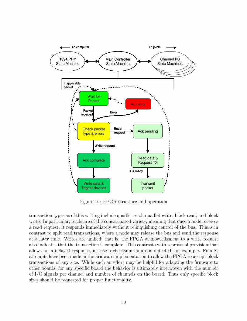
Figure 16: FPGA structure and operation
transaction types as of this writing include quadlet read, quadlet write, block read, and blockwrite. In particular, reads are of the concatenated variety, meaning that once a node receivesa read request, it responds immediately without relinquishing control of the bus. This is incontrast to split read transactions, where a node may release the bus and send the responseat a later time. Writes are unified; that is, the FPGA acknowledgment to a write requestalso indicates that the transaction is complete. This contrasts with a protocol provision thatallows for a delayed response, in case a checksum failure is detected, for example. Finally,attempts have been made in the firmware implementation to allow the FPGA to accept blocktransactions of any size. While such an effort may be helpful for adapting the firmware toother boards, for any specific board the behavior is ultimately interwoven with the numberof I/O signals per channel and number of channels on the board. Thus only specific blocksizes should be requested for proper functionality.
22
6.2 Channel Modules
As detailed in the description of the amplifier section, each channel contains one controlaxis worth of I/O, namely an ADC, DAC, digital potentiometer, encoder lines, amplifierenable line, and amplifier status line. The FPGA interacts with the ADC, DAC, and digitalpotentiometer via the Serial Peripheral Interface (SPI). The encoder signals originate as ananalog voltage, but arrive at the FPGA in digital form after level translation in the amplifiersection. Counter logic on the FPGA converts the incremental encoder pulses into motorposition and velocity measurements. The enable and status lines are simple digital signals.
Communication with these I/O devices is performed in parallel with the IEEE 1394state machine described above. The read (input) devices, namely the ADC and encoder, runcontinuously and transfer their data into FPGA buffers as soon as conversion or computationresults are complete. The ADC is utilized in this manner because its conversion time,roughly 2 µs, is long compared to the bus transaction time, so it is not advisable to starta new conversion and wait for the result whenever a read request is received. This impliesthat an ADC conversion result can be up to 2 µs stale, but this is negligible relative tothe Snake Robot servo frequency of 1 kHz (1 ms). The write (output) devices, namely theDAC and digital potentiometer, wait idly for write requests, transfer write data from FPGAbuffers into scratch registers when a request arrives, and perform the operation. The digitalpotentiometer functions as both a read and a write device, though it is not read continuously.
While each SPI device is run in separate submodules, all of the I/O devices for a channelare collectively managed by a higher level state machine. This larger module is replicated foreach amplifier section and runs independently of any others. It is responsible for arbitratingthe shared SPI lines of each channel’s respective ADC, DAC, and digital potentiometer.The ADC and DAC accesses can run simultaneously because even though they share someSPI signals, their data move in different directions (the former on the SDO line and thelatter on SDI) and thus do not conflict. This is a valuable property because both devicesare involved in real-time operation. Since the digital potentiometer is both a read anda write device, however, its accesses must be handled as a special case. A read requestfrom the computer targeting the digital potentiometer will instruct the FPGA to pauseADC conversions, read the digital potentiometer data into an FPGA register, and thenresume ADC conversions. The computer then sends a read request for the stored value. Asimilar procedure is followed for digital potentiometer write requests by pausing the DACtemporarily. This extra complexity does not affect real-time performance because digitalpotentiometer accesses should be a relatively rare event.
Another special case is establishing the motor current limit through the DAC. Becausethe same dual-channel DAC is also used for setting the motor command, both channelscannot be written simultaneously, and thus must be performed in separate transactions.While such a limitation would seem to compromise real-time performance, setting of thecurrent limit is expected to be a seldom act, for example, as an initialization step. Undernormal operation only the motor command is set.
23

6.3 Global I/O Module
The amplifier enable lines and fault status flags were previously described in conjunction withtheir associated channels. However, in order to combine these signals with global events, theyare passed on to higher level firmware for management. Introducing an enable mask allowsdifferent combinations of amplifiers to be enabled (or disabled) arbitrarily, so that it can bedone in software using a single write transaction. Absent of this feature, separate transactionswould be required for different amplifier enable requests. Managing the enable lines globallyallows us to disable them automatically based on a watchdog timeout, discussed below. Italso facilitates convenient grouping of the enable lines, status lines, watchdog timeout flag,and board identifier in order to report them as a single status register. Finally, a logiccombination of enable and fault signals are used to set the LED array on the board.
The global I/O module includes an optional watchdog resource, which is activated viasoftware by setting the desired timeout period. The value is in terms of a 5.2083333 µs(49.152/256 MHz) counter. As the counter is an unsigned 16-bit integer, the longest timeoutperiod that can be specified is approximately 0.34 seconds. A timeout occurs when the valueof the free running counter matches or exceeds that of the timeout period, at which pointall amplifiers are disabled. The counter is cleared whenever a write transaction is received,so timeouts are avoided so long as write transactions are issued at a rate faster than thetimeout period. Watchdog functionality is disabled by setting the timeout period to zero,the default setting.
Two seldom used features include the ability to access the registers of the IEEE 1394physical layer chip, and a read-only version number register that is meant to be set duringfirmware synthesis. This latter function was quickly deprecated in favor of using software tostore version numbers in the digital potentiometer EEPROM.
6.4 Address Maps
All of the I/O resources described thus far are directly accessible by computer software viaquadlet transfers, with the desired device specified by an appropriate value in the addressfield of the packet header. In all cases, the FPGA checks the destination ID field in thepacket header and only acts if the value matches the local node ID, which is automaticallyassigned by the physical layer. Furthermore, it only acts if the specified transaction codeis supported. Otherwise packets are considered inapplicable to the node and are silentlyignored. When active, the FPGA reads data from or writes data to intermediate buffers asdescribed previously.
The address field for quadlet transfers is interpreted as follows: bits 7-4 address a channel,while bits 0-4 address a device on that channel. The address map is listed in Table 1. Onedetail of note is that channel devices begin at channel address 1, as channel address 0specifies the global I/O module, whose address map is also shown in the table. The address
24

Bits 7-4 Bits 3-0 Description0 (Global Registers) 0 Status Register
1 IEEE 1394 Physical Layer Chip Control Register2 IEEE 1394 Physical Layer Chip Data Register3 Watchdog Timeout Period Register4 Version Number Register (deprecated)
1-7 (Channel Select) 0 ADC Data Register1 DAC Control Register2 Digital Potentiometer Control Register3 Digital Potentiometer Data Register4 Quadrature Encoder Preload Register5 Quadrature Encoder Data Register6 Encoder Period Data Register7 Encoder Frequency Data Register (not implemented)
Table 1: Device map of quadlet transaction address field
segmentation reveals our assumptions on the number of devices per channel and the numberof channels per node.
In contrast, the devices involved in block reads and writes are fixed according to itsposition in the data block. Also, only certain devices are accessible through block transfers,i.e. those necessary for real-time operation. Figure 17 depicts the respective packet formatsexpected by the FPGA, as well as how it interprets the data fields. The FPGA firmware ismeant to handle write blocks of a fixed size due to the simplicity and reliability of such anapproach. Thus the MSB of each data quadlet is interpreted as a valid bit, which is set bysoftware to indicate to the FPGA whether or not the corresponding device is to be written.
7 Software API
7.1 Block Diagram
We developed a generic, intuitive API for the control hardware described above. The inter-face has the three-layer hierarchy shown in Figure 18. The top layer consists of abstract I/Ooperations that can be used for different robots. It includes commands to latch all sensorsand to apply all outputs, which are often supported by the hardware (e.g., simultaneouslysampled ADCs and double-buffered DACs). All read and write operations are performed fora single axis at a time, requiring only primitive C data types (e.g., int, long).
25

Figure 17: Block read (left) and write (right) packet formats as interpreted by the FPGA
The second layer, which implements the abstract interface for the Snake Robot, is cus-tomized to work with data blocks, since for efficiency reasons the data for the multiple axesof a node are bundled into a single bus transaction. This layer provides access to individualaxes via local buffers that are filled by LatchAllSensors and emptied by ApplyAllOutputs.So that a fixed block size can be used to simplify the FPGA implementation, the secondlayer maintains a valid bit for each axis that indicates to the FPGA whether or not to writethe corresponding axis. The bottom layer contains function calls to the IEEE 1394 APIlibrary (libraw1394), though for real-time performance considerations RT-FireWire [12] isan alternative of interest. By carefully designing a general robot control API, the developedsoftware can be easily maintained, and the system can be used in other surgical robots.
7.2 Application Programming Interface
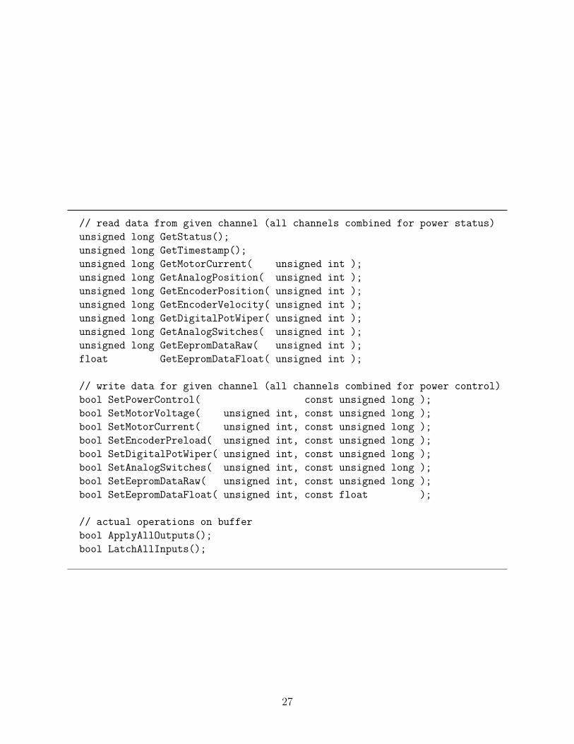
The methods of the API are listed below. The data formats produced or expected by thehardware are diverse, as they are specific to each device. In order to maintain uniformityin the data types of the API arguments and return values, the library manipulates thedata in ways that the calling code must handle properly. Some of the less straightforwardconsiderations are detailed as follows.
The ADC, through which analog potentiometer and motor current measurements areobtained, reads voltages in the range of 0 to 2.5 V. However, it reports them as signed 14-bit integers relative to 1.25 V. To match the API convention, the library converts these to
26
// read data from given channel (all channels combined for power status)
unsigned long GetStatus();
unsigned long GetTimestamp();
unsigned long GetMotorCurrent( unsigned int );
unsigned long GetAnalogPosition( unsigned int );
unsigned long GetEncoderPosition( unsigned int );
unsigned long GetEncoderVelocity( unsigned int );
unsigned long GetDigitalPotWiper( unsigned int );
unsigned long GetAnalogSwitches( unsigned int );
unsigned long GetEepromDataRaw( unsigned int );
float GetEepromDataFloat( unsigned int );
// write data for given channel (all channels combined for power control)
bool SetPowerControl( const unsigned long );
bool SetMotorVoltage( unsigned int, const unsigned long );
bool SetMotorCurrent( unsigned int, const unsigned long );
bool SetEncoderPreload( unsigned int, const unsigned long );
bool SetDigitalPotWiper( unsigned int, const unsigned long );
bool SetAnalogSwitches( unsigned int, const unsigned long );
bool SetEepromDataRaw( unsigned int, const unsigned long );
bool SetEepromDataFloat( unsigned int, const float );
// actual operations on buffer
bool ApplyAllOutputs();
bool LatchAllInputs();
27

Figure 18: General robot control API
unsigned 14-bit integers by adding to it the midpoint value of the 14-bit range. Stated ex-plicitly, the ADC views the range 0 to 2.5 V as -1.25 to +1.25 V, and reports a correspondingvalue in the range -8192 to +8191. The library adds 8192, resulting in an API return valuein the range 0 to 16383, an unsigned 14-bit integer. The caller must treat this accordingly,as the sign is related to the direction of travel.
The DAC, through which motor commands and motor current limits are programmed,outputs voltages in the range 0 to 2.5 V. It accepts as its inputs 16-bit unsigned integers,making the mapping intuitive. Note however that the direction of the motor depends onwhether the DAC output is above or below the midpoint (1.25 V), and its speed depends onthe absolute difference from the midpoint. In this sense the motor command can be viewedas a signed value centered about this nonzero midpoint.
The controller provides two types of encoder counts. The main type counts the numberof pulses, which can be used to measure incremental movement. Because an overflow flagis asserted when the count drops below 0 or increases beyond the 24-bit counter maximum,it is important to preload the counter with the midpoint value during initialization. Thesecondary measurement is a 16-bit counter representing the number of 1.302083333 µs (768
28

Bits 31-28 27-24 23 22-16 15-8 7-0Unused(4) Board ID(4) WD Timeout(1) Status(7) EN Mask(8) Amp EN(8)
Table 2: Status code definition
kHz) clocks elapsed between encoder pulses. This is potentially useful for measuring rela-tively slow motor velocities, as in this regime there is a resolution problem in simply dividingthe number of encoder pulses by the elapsed time. This count should be interpreted as asigned value as it starts from zero and increments or decrements depending on the motordirection.
The digital potentiometer wiper value is an unsigned 10-bit value, where 0 sets the wiperto the A terminal and the maximum value sets it to the B terminal. Given the circuitconnections, this means that the motor current feedback gain increases with the wiper valueaccording to
G =12.1 Ω + 10 Ω × (wiper/1023)
1.5 Ω + 10 Ω × ((1023 − wiper)/1023). (1)
The 10 Ω factor that appears in this formula represents the nominal resistance of thedigital potentiometer. Through our tests we have found this value to vary widely by device,so gains should be tuned per board-motor pair. The gain factor for this stage is nominally2, so a reasonable initial wiper value for the Snake Robot would be 375.
An EEPROM is embedded within each channel, so accessing it requires two tiers ofaddressing, one to specify the channel and the other to specify the EEPROM location withinthat channel. Thus the index argument for EEPROM access is interpreted slightly differently.Bits 7-4 of the index now select the channel, and bits 3-0 select the EEPROM word withinthat channel. In contrast, bits 3-0 select the channel for the other devices. The API alsoallows higher level code to store single-precision floating-point values in EEPROM. It doesso by splitting the 32-bit data type into two 16-bit words at the library level, using twoEEPROM locations for their storage. Note that BCD and floating-point representationsoccupy the same memory space.
Each block read via LatchAllSensors fetches, in addition to ADC and encoder data,a status and a timestamp. The status (Table 2) is a 32-bit value that is a combination ofamplifier enable bits and mask, amplifier status flags, watchdog timeout flag, and board ID(set by the onboard rotary switch). The timestamp, meanwhile, is a 32-bit value indicatingthe number of 49.152 MHz clock cycles elapsed since the previous LatchAllSensors call.
As of this writing the API has not been tested for CISST compatibility, but integrationis in progress.
29

Figure 19: Test and configuration program
7.3 Demonstration
A Qt-based graphical user interface program (Figure 19) is being developed to enable testingand configuration of the various features of the board. It allows the user to control the motorvoltage and current limit for each axis, as well as view their respective analog potentiometer,motor current, and encoder measurements. On the same screen the user can adjust thedigital potentiometers and view the resulting feedback gains. The GUI offers a convenientmechanism for switching between speed and torque control as well. A dedicated EEPROMtab contains controls that allow for reading and writing the EEPROM on any axis, in bothbinary and floating-point representations.
30

This demonstration program is also intended to test the API in order to expose andaddress any remaining issues. Finally, the program serves as a reference implementationfor usage of the API. At present the code is not compatible with the CISST libraries, butintegration is expected to take place in the near future. All source code, design files, anddocumentation referred to in this paper are stored in the Electronics SVN repository [25].
8 Experiments
8.1 Setup and Verification
A conventional Linux desktop computer is used for the initial experiments reported below,while a real-time version of Linux, such as the Real-Time Application Interface (RTAI) andQNX, will be used to run the robot control software. The tests were run at 400 Mbps withone node connected to a 2 GHz Pentium 4 computer by a 6-foot IEEE 1394 cable.
As explained previously, the FPGA performs a read transaction as a concatenated read,which entails a request from the computer, an acknowledgment from the node, and a dataresponse from the node (there is also a final acknowledgement from the computer to thenode). There is no protocol delay (i.e. no busy wait) between receiving a read requestand generating a response. Similarly, write transactions are unified, so there is no delaybetween the receipt of a write request and the execution of the request. Because I/O deviceaccess times are negligible relative to the system bandwidth, loopback tests of the DAC-to-ADC pair and digital I/O consistently return the appropriate values. Bus contention isnot expected because (1) the computer is implemented as the bus master and the nodes asslaves; and (2) no devices unrelated to the control system will be attached to the bus.
The amount of various component-wise tests performed is voluminous and are not re-peated here. Rather, the findings of these tests have been integrated into this report, whiletest code and their noteworthy results have been stored in the Electronics SVN repository.The demonstration GUI presented in the previous section represents the culmination of allverification of the hardware components, API, and their integration.
8.2 Quadlet Transfers
Figure 20 shows the timing results of 9,000 iterations of quadlet reads and writes.
The read times appear in three principal bands (30, 42, 49 µs) and the write times in two(27, 42 µs), possibly due to variability in discrete transaction sequences (e.g. request-ack-response); the average read and write times are 34.5 and 30.2 µs respectively—each respectivelow band is most common. We plan to investigate these regular distribution patterns shouldthey arise under a real-time operating system.
31

Figure 20: IEEE 1394 quadlet read and write transaction times
We note that there are significant latencies in the bus transactions [18, 19, 21]. In a stan-dard servo control implementation (read-control-write) for a seven-axis robot, a combinedread/write time of about 453 µs leaves only 547 µs for control computations at 1 kHz, and isnot even feasible at 8 kHz. Given that the bus speed is 400 Mbps, and that the IEEE 1394physical layer itself should not impose appreciable delays, we conclude that software over-heads are a predominant factor in the latency, as in [13]. As we concluded in our previouswork, it is necessary to bundle the data for multiple axes into blocks in order to overcomethis limitation.
8.3 Block Transfers
Figure 21 shows a raw sampling of read and write times over the full range of allowableblock sizes, up to the maximum of 512 quadlets for the 400 Mbps mode. Blocks sizes aremeasured in quadlets, as IEEE 1394 requires packet sizes to be in multiples of 32 bits. Theplots indicate base latencies of about 33.2 µs for reads and 30.7 µs for writes, which closelymatches our previous findings.
Based on the slopes of transaction time vs. block size, we compute average speeds ofroughly 360 Mbps for block reads and 290 Mbps for block writes. Neither value reachesthe nominal 400 Mbps rate due to protocol handshaking and other overheads, but it defies
32

Figure 21: IEEE 1394 transaction times vs. block size
intuition that reads are faster than writes since the former is a slightly more complicatedtransaction type and incurs greater latency. A possible explanation may involve differencesbetween how the computer and FPGA acquire bus access. We intend to resolve this anomalyin future work. At any rate, the results suggest that the number of axes can be scaledsignificantly with negligible incremental time consumption.
8.4 Discussion
Variability in the transaction times (about 20 µs, based on the noisiness of the plots) andsporadic but high-value outliers may be caused by underlying operating system activity, aswe use conventional Linux for development purposes. The former observation may also beexplained by variability in obtaining bus access. A real-time operating system will be usedto run robot control software, and we would like to obtain performance measurements undersuch an environment as well.
33

Overall, the transaction times are well above theoretical maxima. For example, a quadletread, 296 total bits, should only require a fraction of a microsecond to complete at 400 Mbps.We believe that software overhead is the primary source of concern in our system, and hopeto reduce this in the future. Nevertheless, because software overhead should be relativelyindependent of data size, these results indicate that the most efficient approach is to useone block read to obtain all feedback data (from all joints serviced by the node), and oneblock write to send all command signals. In a standard read-control-write implementation,a combined block read/write time of about 65 µs would leave a generous 935 µs for controlcomputations at 1 kHz, but only 60 µs at 8 kHz, and 35 µs at 10 kHz. IEEE 1394 supportsisochronous transfers, which occur at a frequency of 8 kHz and may therefore be more efficientfor control at this frequency.
9 Ongoing and Future Work
As of this writing, the presented controller is complete and ready for integration. Theremaining work involves the integration itself. First, the API must be integrated into theCISST Library [29] so that is compatible with existing robot control software, and to facilitateits future use. The next step is to modify the Snake Robot control software to use this APIand controller. We hope that our careful efforts in crafting the API will allow for a smoothtransition. We would like to experiment with QNX, a real-time Linux-based operatingsystem that is reportedly being used by several robotics groups, by using it to run the newSnake Robot. It would be interesting to see whether usage of a real-time operating systemhas a significant impact on bus transaction times. Meanwhile, a heatsink-mount must befabricated in order to physically attach the controller to the robot. While assembling themotor connectors, a key detail to remember is that the pinout of the motors changed afterthe circuit boards were fabricated.
Presently we expect to achieve real-time performance for one node, but it is uncertainwhether this will hold when multiple nodes are connected. One way to alleviate this concernis to employ single transactions that encompass all nodes. This is largely if not entirelyan FPGA implementation. The computer can send write commands by broadcasting largepackets and allowing each FPGA to extract its own segment of data. Similarly-spirited readtransactions appear to be somewhat more challenging to perform due to the nature of thearchitecture. The feasibility of using isochronous transactions for this purpose should beexplored.
Ultimately the goal is to further surgical robotics research. One immediate project en-abled by this work is the convenient deployment of an additional Snake Robot for taskssuch as camera manipulation. Other potential applications include dexterous ultrasoundimaging and ablation. The API will be made compatible with a standard medical roboticsframework, the Surgical Assistant Workstation [5].
34

10 Conclusions
Though parallel buses such as ISA, Q-Bus, Multibus, and VME have become tried-and-trueinterfaces for robot control, they are increasingly deprecated with the emergence of IEEE1394, PCI Express, and Ethernet-based protocols, which feature greatly simplified cabling.These high speed serial networks provide higher performance than traditional field buses,such as CAN, SERCOS, and RS-485, which have also been used for real-time control.
The ability of the IEEE 1394 bus to multiplex a large number of data channels helps toreduce wiring complexity, making systems more robust and scalable to many axes of con-trol. Centralized processing eases intra-robot (e.g. master-slave) communication and allowssystems to utilize ever-advancing computing power. Such a setup simplifies the softwaredevelopment environment, which is especially advantageous in areas such as research andeducation, where typical users are not proficient with software development using embeddedmicroprocessors and associated tools.
This paper presents a scalable controller architecture based on IEEE 1394 for communi-cation between the computer and actuated joints. A key element is the use of programmablelogic, such as an FPGA, to provide link layer services for the network by routing read andwrite requests to the appropriate hardware device. The advantages of centralizing process-ing and distributing I/O via a high-speed serial network are discussed. The concept wasdemonstrated by a custom controller for the Snake Robot. As the design lends itself towardsmodularity, the theme served as an influence throughout development. With the poten-tial need for many axes of control in surgical robotics research, modular hardware can helpincrease availability and flexibility while making the system as a whole easier to troubleshoot.
Our first prototype consisted of three boards: a commercial FPGA development board,a custom daughterboard with an IEEE 1394 physical layer chip, and custom motor poweramplifiers. After running a number of tests on this setup, we then constructed a secondprototype that combines the first two boards (FPGA and physical layer chip) into a singlecustom board. We also fabricated a new set of amplifier boards implementing several repairsand design changes.
Preliminary performance data, obtained under a conventional operating system (Linux),suggest that this approach is feasible for real-time control with rates up to several kHz;higher rates, such as 10 kHz, appear to be challenging with the current setup based on themeasured latencies.
Though the described control system is not necessarily a novel design given existingtechnologies, we contend that it will ease the development of dexterous robots and allowresearchers to experiment with more robot-assisted surgical tasks.
35

11 Acknowledgments
Special thanks go to Peter Kazanzides for his comprehensive advisement on this project.I would also like to thank Hamid Wasti of Regan Designs, Inc. (Coeur d’Alene, Idaho)for his expertise on the design and layout of the controller boards, and Ankur Kapoor forsharing his knowledge and experience. Finally I thank Russell Taylor for his overall supportof my research and research-related efforts. This work was supported in part by the NationalScience Foundation (NSF) under Engineering Research Center grant #EEC9731748, NSFgrant #MRI0722943, and by Johns Hopkins University internal funds.
References
[1] Simaan, N., R. Taylor, and P. Flint, “A dexterous system for laryngeal surgery,” IEEERobotics and Automation, vol. 1, pp. 351-357, 2004.
[2] Kapoor, A., N. Simaan, and P. Kazanzides, “A system for speed and torque control ofDC motors with application to small snake robots,” IEEE Mechatronics and Robotics,Aachen, Germany, Sep 2004.
[3] Kapoor, A., “Motion constrained control of robots for dexterous surgical tasks,” Ph.D.dissertation, Johns Hopkins University, Sep 2007.
[4] Simaan, N., R. Taylor, and P. Flint, “High dexterity snake-like robotic slaves for mini-mally invasive telesurgery of the upper airway,” MICCAI, Rennes-Saint-Malo, France,pp. 17-24, Sep 2004.
[5] Vagvolgyi, B., S. DiMaio, A. Deguet, P. Kazanzides, R. Kumar, C. Hasser, and R. Tay-lor, “The Surgical Assistant Workstation,” MICCAI Workshop on Systems and Arch.for Computer Assisted Interventions (online at http://hdl.handle.net/10380/1466), Sep2008.
[6] Sarker, M., C. Kim, S. Baek, and B. You, “An IEEE-1394 based real-time robot controlsystem for efficient controlling of humanoids,” IEEE Intelligent Robots and Systems, pp.1416-1421, Beijing, China, Oct 2006.
[7] Baltazar, G. and G. Chapelle, “Firewire in modern integrated military avionics,” IEEEAerospace and Electronic Systems Magazine, vol. 16, no. 11, pp.12-16, Nov 2001.
[8] Robertz, S., K. Nilsson, R. Henriksson, and A. Blomdell, “Industrial robot motioncontrol with real-time Java and EtherCAT,” IEEE Emerging Technologies and FactoryAutomation, pp. 1453-1456, Sep 2007.
36

[9] Lin, S., C. Ho, and Y. Tzou, “Distributed motion control using real-time network com-munication techniques,” International Power Electronics and Motion Control, vol. 2,pp. 843-847, Aug 2000.
[10] Hagn, U., M. Nickl, S. Jorg, G. Passig, T. Bahls, A. Nothhelfer, F. Hacker, L. Le-Tien, A. Albu-Schaffer, R. Konietschke, M. Grebenstein, R. Warpup, R. Haslinger, M.Frommberger, and G. Hirzinger, “The DLR MIRO: a versatile lightweight robot forsurgical applications,” Industrial Robot: An Int’l Journal, vol. 35, no. 4, pp. 324-336,2008.
[11] Szydlowski, C., “Implementing PCI Express for industrial control,” RTC Magazine, vol.13, Sep 2004.
[12] Zhang, Y., B. Orlic, P. Visser, and J. Broenink, “Hard real-time networking onFireWire,” RT Linux Workshop, Lille, FR, Nov 2005.
[13] Sarker, M., C. Kim, J. Cho, and B. You, “Development of a network-based real-timerobot control system over IEEE 1394: using open source software platform,” IEEEMechatronics, pp. 563-568, Jul 2006.
[14] Schneider, S., “Making Ethernet work in real time,” Sensors Magazine, vol. 17, no. 11,Nov 2000.
[15] Kerkes, J., “Real-time Ethernet,” Embedded Systems Design, vol. 14, no. 1, Jan 2001.
[16] Pratt, G., P. Willisson, C. Bolton, and A. Hoffman, “Late motor processing in low-impedance robots: impedance control of series-elastic actuators,” American ControlConference, vol. 4, pp. 3245-3251, Jun-Jul 2004.
[17] Lewellen, T., C. Laymon, R. Miyaoka, K. Lee, and P. Kinahan, “Design of a Firewirebased data acquisition system for use in animal PET scanners,” IEEE Nuclear ScienceSymposium Conference Record, vol. 4, pp. 1974-1978, Nov 2001.
[18] Thienphrapa, P. and P. Kazanzides, “A distributed I/O low-level controller for highly-dexterous snake robots,” IEEE BioCAS, pp. 9-12, Nov 2008.
[19] Kazanzides, P. and P. Thienphrapa, “Centralized processing and distributed I/O forrobot control,” IEEE TePRA, pp. 84-88, Nov 2008.
[20] Walls, B., M. McClelland, S. Persyn, and D. Werner, “Leveraging flight heritage to newCompactPCI space systems: a fusion of architectures,” Digital Avionics Systems, vol.2, pp. 8C41-8C47, 2001.
[21] Thienphrapa, P. and P. Kazanzides, “A scalable system for real-time control of dexteroussurgical robots,” IEEE TePRA, pp. 16-22, Nov 2009.
[22] Ethernet Powerlink: http://www.ethernet-powerlink.org/.
37

[23] EtherCAT Technology Group: http://www.ethercat.org/.
[24] Controller Area Network: http://www.can-cia.org/.
[25] Electronics SVN repository: https://svn.lcsr.jhu.edu/electronics/.
[26] Huang, R., P. Thienphrapa, and P. Kazanzides, “Calibration of the Snake amplifierboard,” Internal report, May 2009.
[27] Altera Corporation, “Cyclone II device handbook,” 2008.
[28] Kazanzides, P., “Bridge motor amplifier with speed control,” Internal report, Dec 2006.
[29] CISST Library Homepage: https://trac.lcsr.jhu.edu/cisst.
38