a coloured petri net methodology and library for security
TRANSCRIPT

1
A Coloured Petri Net Methodology and Libraryfor Security Analysis of Network Protocols
San Choosang and Steven GordonSirindhorn International Institute of Technology
Thammasat UniversityBangkadi, Thailand 12000
Email: [email protected], [email protected]
Abstract—Formal methods are often used to prove prop-erties of network protocols, including required securityproperties. However for a protocol modeller the techniquesavailable for security analysis often require expert knowl-edge of the technique. Also the tight coupling of protocolmodel and security attacks limit re-use of models. WithColoured Petri nets as the selected formal method, this paperproposes a methodology to support a modeller in performingsecurity analysis of a protocol. The methodology enhancesthe re-usability, extendability and readability of protocoland attack models, with the aim of simplifying the tasksof the modeller. Key to the methodology is the decouplingof the protocol and attack models by using the hierarchicalstructure of Coloured Petri nets. Also a library of attackmodules is developed based on Dolev-Yao assumptions;the modules can be composed to create complex attacksand re-used across different protocols. To demonstrate themethodology, a case study analysing the ZigBee RF4CEpairing protocol is presented. The case study shows the easeat which attacks can be integrated and how the methodologyaddresses the state space explosion problem. The impact oftwo attacks on the ZigBee protocol are analysed, showingseveral scenarios which lead to a mismatch in state at theZigBee devices.
Index Terms—security analysis, formal methods, commu-nication protocols, ZigBee RF4CE, Coloured Petri nets
I. INTRODUCTION
There has been a rapid growth in the development ofcommunication protocols to improve the capability andthe performance of networking technology. Significanteffort is directed to the design of new network protocolsby researchers, companies and standard development or-ganisations. Their primary focus is on performance, anal-ysed using mathematical and simulation models. Howeversecurity of protocols is also important.
There is a wide body of research addressing securityanalysis of protocols [2]. The majority of this researchconcentrates on building a model of a protocol andproving security properties in a mathematical formalism.Although able to produce proofs of security properties,the two main limitations of these approach are:• Difficult for protocol modellers to use: the tech-
niques require detailed knowledge of the mathemat-ical methods to create a model.
Manuscript received April 4, 2012; revised June 13, 2013; acceptedJuly 8, 2013.
This work was supported by the National Research University Projectof Thailand, Office of Higher Education Commission.
• Lack of integration with other design steps: thesecurity method cannot be (even partially) re-usedfor performance analysis, and is normally not in aform to be used in a standard document.
To address these issues, one alternative is to use for-mal models that offer graphical notations for modellingprotocols, thereby making it easier for protocol modellersto analysis security properties without being experts inthe underlying mathematics. Coloured Petri nets (CPNs)[1] are one such formal method. Recently researchershave been applying CPNs to analyse the security ofnetwork protocols [3], [4], [10], [15], [16], [17], [18].Our research presents a new methodology that combinesideas from recent research, as well as introduces new con-cepts to prove security properties of network protocols.Our proposed methodology separates the model of theprotocol from models of security attacks. We have alsodeveloped a library of attack modules that can be re-usedin different protocols. We present the steps that a modelleruses to incorporate attack modules from the library intotheir protocol model. We also include mechanisms thatcan help alleviate the state space explosion problem.A significant difference between our methodology andother approaches (e.g. [3], [17]) is that we require themodeller to analyse attacks in an iterative manner. Thatis, our approach encourages the modeller to analyse asingle attack at a time, where as [3] and [17] havethe advantage in that they allow analysis of multipledifferent attacks, potentially detecting unknown attacks.We believe the extra effort required by the modeller toanalyse single attacks at a time is a reasonably trade-off for the benefits of re-usable, extendable and readablemodels. We demonstrate our methodology with a smallbut relevant case study that analyses multiple attacks onthe ZigBee RF4CE wireless networking protocol [5].
This paper is structured as follows. In Section II wepresent the background on CPNs and protocol modelling.Section III reviews the related work. Our methodologyis presented in Section IV, giving both an informaldescription and formal definition of the steps to be takenby the protocol modeller. Section V introduces the casestudy, the ZigBee RF4CE pairing protocol. A CPN modelof the protocol with two example attacks incorporate ispresented, along with analysis results in Section VI and
JOURNAL OF COMPUTERS, VOL. 9, NO. 2, FEBRUARY 2014 243
© 2014 ACADEMY PUBLISHERdoi:10.4304/jcp.9.2.243-256

2
Section VII, respectively. We close with conclusion andfuture work in Section VIII.
II. BACKGROUND
A. Formal Modelling of Protocols
Formal methods can be used for the specification andanalysis of communication protocols to provide insightsinto the system behaviour, early detection of errors in thedesign process, remove ambiguities from specificationsand to prove correctness of the protocols [6]. Protocolverification is one common use of formal methods, whereproofs are made that a protocol satisfies a set of require-ments or desired properties (e.g. faithful refinement of aservice, absence of deadlocks). Although not as common,formal methods can also be used to analyse the perfor-mance and security of properties. It is more commonthat performance analysis is undertaken with purpose-built network simulators (e.g. OPNET, ns2), while variousmathematical techniques are used for security analysis.Seldom is a single formal method used for the analysisof functional, performance and security properties of aprotocol, making it difficult for a protocol modeller togain the expertise to perform all types of analysis.
Coloured Petri nets [1] are one formal method whichhave the potential of supporting functional, performanceand security analysis of protocols. CPNs are well suitedto modelling protocols as they support concurrency andnon-determinism, and allow for modelling at differentlevels of abstraction, such as a service and a protocol.Importantly they have a graphical notation, simplifyingthe development and validation of protocol models andhave strong computer tool support, CPN Tools [7]. Thereare many case studies applying CPNs to protocol veri-fication [8], [9], [10], [11], as well as for performanceanalysis [12], [13], [14] and security analysis [4], [3].Ideally a protocol modeller could create a single CPNmodel of a protocol, from which they can automaticallyprove functional and security properties of the protocoland conduct a performance evaluation. One challenge inachieving this is simplifying the effort needed by theprotocol modeller in incorporating security attacks intoan existing protocol model.
A common approach for security analysis of protocolsis to create a model of the protocol and then modifythat model to incorporate selected attacks. Using a formalmethod such as CPNs to create the model then allowsanalysis of the impact of attacks on the protocol, e.g. usingmodel checking or state space analysis. Incorporatingan attack into an existing model commonly involvesmodifying the structure of the existing model [10], [15],[16]. However this often makes the protocol model andattack tightly coupled, limiting the chances of re-using orextending the models and sometimes reduces readabilityof the model. The focus of this paper is decoupling themodel of the protocol from the attack, so that a mod-eller can perform security analysis while enhancing thereadability, re-usability and extendability of their models.
B. Coloured Petri Nets
CPNs are a directed graph with two types of nodes: aset of places, P , and a set of transitions, T , represented byellipses and rectangles, respectively. Places and transitionsare connected by directed arcs: input arcs (place totransition) and output arcs (transition to place). Placesare typed by a colour set and the values that marks onthe places are called tokens. Transitions and arcs can alsohave inscriptions (expressions) to control the execution ofthe model. The execution of a CPN consists of occurrenceof transitions. A transition can occur if and only if: for allinput places, sufficient tokens exist that satisfy the inputarc inscriptions, and the transition inscription evaluates totrue.
The formal definition of non-hierarchical CPNs follows[1]. (Hierarchical CPNs, which are used in this paper,extend this definition; in Section IV-C we will show theextended definition for our models).
Definition 1. A non-hierarchical Coloured Petri Net is anine-tuple CPN = (P, T,A,Σ, V, C,G,E, I), where:
1) P is a finite set of places.2) T is a finite set of transitions T such that P∩T = ∅.3) A ⊆ P × T ∪ T × P is a set of directed arcs.4) Σ is a finite set of non-empty colour sets.5) V is a finite set of typed variables such that
Type[v] ∈ Σ for all variables ∀v ∈ V .6) C : P → Σ is a colour set function that assigns a
colour set to each place.7) G : T → EXPRV is a guard function that assigns
a guard to each transition t such that Type[G(t)] =Boolean.
8) E : A → EXPRV is an arc expression functionthat assigns an arc expression to each arc a suchthat Type[E(a)] = C(p)MS , where p is the placeconnected to the arc a.
9) I : P → EXPR∅ is an initialisation function thatassigns an initialisation expression to each place psuch that Type[I(p)] = C(p)MS .
For the inscriptions (C,G,E, I) EXPR denotes theset of expressions provided by the inscription languageCPN ML (an extension of Standard ML). The type ofan expression e is denoted by Type[e]. MS refers to amultiset. Graphically, in this paper places are illustratedas eclipses, transitions as rectangles, guards in squarebrackets, and all other inscriptions located next to thecorresponding place/arc.
III. RELATED WORK
Various researchers have investigated the applicationof formal methods to prove security properties, includingusing CPNs. CPNs offer the advantage of being able toautomatically generate proofs of security properties (likeother mathematical approaches), while also providing agraphical, simple-to-use notation making creation andvalidation of models viable for protocol modellers. Herewe focus on recent advances in using CPNs in a generalmethodology for modelling security protocols.
244 JOURNAL OF COMPUTERS, VOL. 9, NO. 2, FEBRUARY 2014
© 2014 ACADEMY PUBLISHER

3
Xu and Xie [16] present a methodology for modellingattacks in security protocols using CPNs, and apply itto the Andrew Secure RPC protocol. The methodol-ogy recommends separating the models of the attacksfrom the original protocol model. However no detailsare given as to how to do this for a specific set ofattacks. The modelling constructs and declarations tobe used are not presented by the authors. Xu and Xiedemonstrate the modelling of an attack on the AndrewSecure RPC protocol. Using state space analysis theyshow that the introduction of an attack in the protocolexposes a weakness (which is well known for AndrewSecure RPC). However this can be considered a ’toy-example’ in terms of complexity. Many protocols willbe much more complex, and hence the state explosionproblem will arise. Xu and Xie give no techniques foralleviating the state explosion problem.
Our research extends upon the work by Xu and Xie.In a similar manner we keep the models of attacksindependent from the original protocol model. Further-more, we also provide a library of models of differentattacks and design the methods for incorporating intodifferent protocols. In addition, we present techniquesfor alleviating the state explosion problem when multipleattacks are allowed (a case not considered by Xu and Xie).
Suriadi et al. [10] has applied CPNs to model privacyenhancing protocols, in particular PIEMCP. They presentthe concept of abstracting from the cryptographic opera-tions (i.e. not implementing the encryption ciphers) so themodelling can focus on the protocol exchange. To handlemultiple types of attacks in one model they introduceconditional statements on selected arc inscriptions inthe CPNs. Temporal logic is applied on the state spaceto prove security properties. While providing detailedanalysis of PIEMCP, the approach used by Suriadi et al.is not directly applicable to other protocols. In particular,they only model attacks from insiders (nodes participaingin the protocol that behave maliciously), but not fromoutsiders. Numerous attacks on protocols involve out-siders (in many cases, insiders are assumed to be trusted).The approach of modelling attacks as conditions on arcinscriptions means the attack models cannot be easilyapplied to different protocols.
Our research provides a different and more genericmethodology for modelling attacks than that proposed bySuriadi et al., focussing on attacks by external nodes, notinsiders.
Al-Azzoni et al. [3] presents one of the first method-ologies for verifying cryptographic protocols with CPNs.Starting with an existing model of a protocol with nointruder, they add a substitution transition on the top-level page to represent the intruder. Changes to themodel include new declarations and an intruder page thatmodels the attacks on communication channels of thenormal entities in the protocol. The attacker model allowsfor interception, modification and insertion of messages.To reduce the state space, they introduce new placesto the existing entities so that unnecessary interleaving
between subprocesses of the entities are restricted. Themethodology is demonstrated for the TMN authenticatedkey exchange protocol.
Permpoontanalarp and Changkhanal [17], [18] havedeveloped a modelling methodology that extends the workof Al-Azzoni et al. [3] and is similar to Xu and Xie,modelling the attacker as a independent entity betweeninitiator and responder in a protocol. The methodologyincludes an approach for defining vulnerability events,as well as obtaining a trace of events that lead to adiscovered attack. The methodology has been appliedto two examples: TMN authenticated key exchange andMicali’s contract signing protocol.
The works of both Al-Azzoni et al. and Permpoon-tanalarp and Changkhanal are similar in how attackersare introduced. Our research extends upon their approach,using a similar methodology. However a key differenceis the detail in which attacks are modelled. Their workpresent models of attacks on specific protocols, namelyTMN. Their attack models are general, in that they allowthe attacker to intercept and modify any message. This hasthe advantage that the resulting state space can be usedto identify different possible successful attacks, includingunknown attacks. The disadvantage is that the state spacesize may increase rapidly.
To overcome the state space explosion, our methodol-ogy allows the modeller to limit the types of messagesthat can be intercepted, modified and inserted. But thiscomes at the expense of more specific attack models,i.e. the analysis identifies a only restricted set of possiblesuccessful attacks. In order to overcome this limitation, amodeller must model and analyse specific attacks sepa-rately. Although extra effort is therefore required by themodeller, we believe this will fit with the incrementalapproach modellers often use, especially when supportedby the library of attack modules provided.
IV. SECURITY ANALYSIS METHODOLOGY
A. Methodology Overview
We propose a methodology for modelling and analysingnetwork protocols from a functional and security view-point using Coloured Petri nets. The methodology sets outthe steps that a modeller should follow, defines specificparts of the CPN protocol model and offers a library ofcommon attacks. The main steps are:
1) Create an original protocol model: The model ofthe protocol must be created following the protocolmodelling approach described in Section IV-B.
2) Functional analysis of the protocols: analyse theprotocol model to investigate unexpected be-haviours of the protocol by using state space anal-ysis.
3) Attack integration: add the attack modules into thecommunication channels of the original protocolmodel.
4) Security analysis: analyse the updated protocolmodel, investigating the behaviour when attacks arepresent.
JOURNAL OF COMPUTERS, VOL. 9, NO. 2, FEBRUARY 2014 245
© 2014 ACADEMY PUBLISHER

4
The steps are designed with three primary featuresin mind: re-usability, extendability and readability. Notethat the last two steps will in practice be performediteratively using different attacks, i.e. one attack modelper computation of the state space. For example, a sim-ple, known attack may be modelled and analysed first.Once completed, a more complex attack is modelled andanalysed, and so on until the modeller is confident of theprotocol strengths.
Developing a CPN model of a communications pro-tocol requires significant time and effort. Typically CPNmodels are created to support functional analysis of theprotocol, although performance analysis is also possible.Our methodology requires the modeller to use definedconstructs for modelling the communication channel inCPNs. Although this limits the modeller, the constructsare sufficient to cover most common scenarios (e.g. or-dered or unordered channels, lossy or lossless channels).And importantly by using the defined constructs the mod-eller can re-use the functional protocol model for securityanalysis with few changes. Re-using the same protocolmodel is a significant benefit of our methodology asthe modeller avoids challenges of managing two separatemodels.
A key idea in our methodology is that the protocolmodel should support analysis of multiple attacks. Weimplement attacks using common attack modules thatcan be composed to form more specific and complexattacks. The attack modules are not specific to a protocoland therefore are re-usable across different protocols.With our methodology a modeller can concentrate on theprotocol modelling, re-using the library of attack modulesas needed.
The attack modules are designed so that they can becomposed together in different ways to create differentattacks. They can also be easily plugged in to the protocolmodel. This offers extendability, in that many attacks canbe created using the common attack modules.
A key advantage of CPNs over other formal methods isthat their graphical notation allows modellers to visualisethe protocol operation. However it is still possible fora modeller to make a CPN model difficult to read (e.g.very long arc inscriptions, many crossing arcs, poorlypositioned places and transitions). In designing the attackmodules and separation from the protocol model in ourmethodology, we focussed on maintaining the readabilityof the CPN. Rather than modelling attacks as a set ofconditional statements in inscriptions on arcs within theprotocol model (e.g. [10]) we only require very minormodifications to the existing protocol model so that itmaintains its readability.
These three features—re-usability, extendability andreadability—are further explained when describing theindividual steps in the remainder of this section. They aredemonstrated in the case study on RF4CE in Section VI.
B. Functional Protocol Model
The first step of this methodology is to create a CPNmodel of the protocol under investigation. CPNs are oftenused to analyse functional behaviour of protocols (e.g. ab-sence of deadlocks, comparison to service specifications)and hence we refer to the original model as the functionalprotocol model.
There are various ways to model a protocol with CPNs[1], [19], depending on the objectives of the protocolmodeller. Although we do not require any specific ap-proach, in our methodology the modeller must modelthe communicating entities independently such that theyonly communicate via a communications channel model.This imposes some limitations on what type of protocolscan be modelled. Our methodology therefore assumes theprotocol under investigation uses:• Unicast communications with only two entities in-
volved. Currently multicast/broadcast and multi-party protocols (e.g. client–server–database) cannotbe modelled.
• A full-duplex communications channel. This in-cludes support for both ordered and unordered chan-nels, as well as lossy and lossless channels. Thechannels can represent a single link or an entirecommunications network.
The required structure of the functional protocol model,i.e. the top-level CPN page, is shown in Fig. 1.
EntityA
A
D
B
C
EntityB
Fig. 1. General Structure of Functional Protocol Model
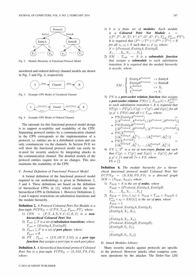
Each protocol entity is modelled by a substitutiontransition, EntityA and EntityB. Each substitution transitionis assigned a sub-module, a CPN page that models theprotocol entity in detail (e.g. packet transmission andreception, timers, processing algorithms). This structure isdefined by a module hierarchy which is a directed graphwith a node for each module and a labelled arc for eachsubstitution transition. Fig. 2 is a graphical representationof the module hierarchy for the functional protocol CPNmodel. The top-level module must have two sub-modules,EntityA and EntityB. Modules Xi and Yi represent a sub-modules under EntityA and EntityB substitution transitionswhich model the detail of each protocol entity. They arenot required—it is the choice of the modeller as to howto model the protocol details.
The modeller is free to model the entities as theychoose. The only restriction is that the entities communi-cate via the four channel interface places, A, B, C and D.The modeller is free to model the channel as they choose,so long as the four places use the same type. Examples of
246 JOURNAL OF COMPUTERS, VOL. 9, NO. 2, FEBRUARY 2014
© 2014 ACADEMY PUBLISHER
5
EntityA EntityB
X1 Xn Y1Yn
X1
Xn
Y1 Y
n
EntityA EntityB
Protocol
Fig. 2. Module Hierarchy of Functional Protocol Model
unordered and ordered delivery channel models are shownin Fig. 3 and Fig. 4, respectively.
A BChannelframe frame
Fig. 3. Example CPN Model of Unordered Channel
A Channel Bframe::queue1 queue2^^[frame]
queue1 queue2
Fig. 4. Example CPN Model of Ordered Channel
The rationale for this functional protocol model designis to support re-usability and readability of the CPN.Separating protocol entities by a communication channelin the CPN corresponds to the implementation of aprotocol, i.e. entities are in a distributed system and canonly communicate via the channels. In Section IV-E wewill show the functional protocol model can easily bere-used for security analysis by integrating attacks inthe communication channel. The detailed models of theprotocol entities require few or no changes. This alsomaintains the readability of the CPN.
C. Formal Definition of Functional Protocol ModelA formal definition of the functional protocol model
required in our methodology is given in Definitions 2,3 and 4. These definitions are based on the definitionof hierarchical CPNs in [1], which extend the non-hierarchical CPN in Definition 1. However Definitions 2,3 and 4 impose restrictions on substitution transitions andthe module hierarchy.
Definition 2. A Protocol Coloured Petri Net Module is afour-tuple PCPNM = (CPN, Tsub, Pport, PT ), where:
1) CPN = (P, T,A,Σ, V, C,G,E, I) is a non-hierarchical Coloured Petri Net.
2) Tsub ⊆ T is a set of substitution transitions, where:Tsub = {EntityA,EntityB}
3) Pport ⊆ P is a set of port places, where:Pport = ∅
4) PT : Pport → {IN,OUT, I/O} is a port typefunction that assigns a port type to each port place.
Definition 3. A hierarchical functional protocol ColouredPetri Net is a four-tuple FCPNH = (S, SM,PS, FS),where:
1) S is a finite set of modules. Each moduleis a Coloured Petri Net Module s =((P s, T s, As,Σs, V s, Cs, Gs, Es, Is), T s
sub, Psport, PT s).
It is required that (P s1 ∪ T s1) ∩ (P s2 ∪ T s2) = ∅for all s1, s2 ∈ S such that s1 6= s2, where:S = {Protocol, EntityA,EntityB,X1, . . . , Xn, Y1, . . . , Yn}
2) SM : Tsub → S is a submodule functionthat assigns a submodule to each substitutiontransition. It is required that the module hierarchyis acyclic, where:
SM :
EntityAProtocol 7→ EntityAEntityBProtocol 7→ EntityBXEntityA
i 7→ Xi
Y EntityBi 7→ Yi
3) PS is a port-socket relation function that assignsa port-socket relation PS(t) ⊆ Psock(t)× P
SM(t)port
to each substitution transition t. It is required thatST (p) = PT (p′), C(p) = C(p′), and I(p)〈〉 for all(p, p′ ∈ PS(t) and all t ∈ Tsub, where:• PS(EntityAProtocol) ={(AProtocol, AEntityA), (DProtocol, DEntityA)}
• PS(EntityBProtocol) ={(BProtocol, BEntityB), (CProtocol, CEntityB)}
• PS(XEntityAi ) =
{(∆EntityA1 ,∆Xi
1 ), . . . , (∆EntityAn ,∆Xi
n )}• PS(Y EntityB
i ) ={(∆EntityB
1 ,∆Yi1 ), . . . , (∆EntityB
n ,∆Yin )}
4) FS ⊆ 2P is a set of non-empty fusion set suchthat C(p) = C(p′) and I(p)〈〉 = I(p′)〈〉 for allp, p′ ∈ fs and all fs ∈ FS, where:FS = {}
Definition 4. The module hierarchy for a hierar-chical functional protocol model Coloured Petri NetFCPNH = (S, SM,PS, FS) is a directed graphMH = (NMH , AMH), where:
1) NMH = S is the set of nodes, whereNMH = {Protocol, EntityA,EntityB,X1, . . . , Xn, Y1, . . . , Yn}
2) AMH = {(s1, t, s2) ∈ NMH × Tsub × NMH |t ∈T s1sub ∧ s2 = SM(t)} is the set of arcs, where
AMH = {(Protocol, EntityA,EntityA),(EntityA,X1, X1),. . . ,(EntityA,Xn, Xn),(Protocol, EntityB,EntityB),(EntityB, Y1, Y1),. . . ,(EntityB, Yn, Yn)}
D. Attack Modules LibraryMany security attacks against protocols are specific
to the protocol. However attacks often comprise com-mon operations by the attacker. The Dolev-Yao [20]
JOURNAL OF COMPUTERS, VOL. 9, NO. 2, FEBRUARY 2014 247
© 2014 ACADEMY PUBLISHER

6
assumptions establish a model of what an attacker cando. According to Dolev-Yao an attacker has full controlover the communication channel and can carry out thefollowing actions:
1) Tapping and storage of all messages that passthrough the communication channel.
2) Forwarding or blocking of messages.3) Generation of forged messages.4) Decryption of cryptographic messages if the at-
tacker has a matching key.5) The attacker can take part in the protocol, so
pretending to be any entity is possible.We use the Dolev-Yao attacker model to create a set of
attack modules: partial CPNs that model the behaviour ofcommon attack operations. The attack modules are:• Interception module (Fig. 5). This module allows the
attacker to intercept a frame that is begin transmittedthrough the communication channel. A copy of theframe is stored for future use.
• Modification module (Fig. 6). This module allowsthe attacker to change the content of the target frame.
• Replay module (Fig. 7) This module allows theattacker to re-send a frame that has previously beenintercepted by the attacker.
• Injection module (Fig. 8) This module allows theattacker to create a new frame and send it to thedestination entity.
• Drop module (Fig. 9) This module allows the at-tacker to discard a frame that is currently beingtransmitted through the communication channel.
• Message generation module (Fig. 10) This moduleallows the attacker to generate a new frame whichwill be injected to the target entity.
1. Change the colour set of places to the protocol modeller design colour set2. Change the arc expression variables to the protocol modeller design variables3. Edit the guard at Intercept transition
ft
1`()
frameframeIntercept
[#FrameType frame = ft]
AttackerDB
Attacker DBFrame
Filter
FrameType
Output
Out UNIT
Input
In FrameIn
Out
Attacker DB
Fig. 5. Interception Module
1. Change the colour set of places to the protocol modeller design colour set2. Change the arc expression variables to the protocol modeller design variables3. Edit the guard at Select transition4. Edit the Modification Function
FunctionModification
ft
1`()1`()
frameframeframeModifySelect
[#FrameType frame = ft]
Output
OutUNIT
After
Attacker DBFrame
To beModify
Frame
Input
InUNIT
Filter
FrameType
Before
Attacker DBFrame
Attacker DB
In
Attacker DB
Out
Fig. 6. Modification Module
The attack modules have several common design fea-tures. Each attack module has an Input place and Output
1. Change the colour set of places to the protocol modeller design colour set2. Change the arc expression variables to the protocol modeller design variables3. Edit the guard at Select transition
frame
1`()1`()
ft
frameframeframeframeReplaySelect
[#FrameType frame = ft]
Output
OutUNIT
B
OutFrame
To beReplay
Frame
Filter
FrameType
Input
InUNIT
Before
Attacker DBFrame
Attacker DB
In
Out
Out
Fig. 7. Replay Module
1. Change the colour set of places to the protocol modeller design colour set2. Change the arc expression variables to the protocol modeller design variables3. Edit the guard at Select transition
ft
1`()1`()
frameframeframeframeInjectSelect
[#FrameType frame = ft]
Output
OutUNIT
B
OutFrame
To beInject
Frame
Filter
FrameType
Input
InUNIT
Before
Attacker DBFrame
Attacker DB
In
Out
Out
Fig. 8. Injection Module
place. A token on the Input place enables the attackto occur while a token in the output place signifiesthe completion of the attack. When composing multiplemodules to create more complex attacks, the Output placeof one module is connected to the Input place of the nextmodule (SectionIV-E further describes how the modulesare integrated).
An attack often involves manipulating frames sentbetween the protocol entities. The success of an attackmay depend on manipulating and storing multiple frames.Therefore we use a single place to store the frames as theyare received and after they are modified. The place to storethe frames is the attackers database of information (themodel could be extended to store information other thanframes if needed). Although only one place is needed, toenhance the readability of the CPN we use a fusion place,Attacker DB, which has two subplaces Before and After.These two subplaces are in fact the same place: a tokenin Before also means that token exists in After.
1. Change the colour set of places to the protocol modeller design colour set2. Change the arc expression variables to the protocol modeller design variables3. Edit the guard at Select transition1`()1`()
ft
frameframeframeDropSelect
[#FrameType frame = ft]
Output
OutUNIT
To beDrop
Frame
Input
InUNIT
Filter
FrameType
Before
Attacker DBFrame
Attacker DB
In Out
Fig. 9. Drop Module
1. Change the colour set of places to the protocol modeller design colour set2. Change the arc expression variables to the protocol modeller design variables3. Edit the guard at Generate Frame transition4. Edit the Frame Generation Function
FunctionFrame Generation
1`()
1`()
n-1 n
GenerateFrame
[n>0]
Limit
INT
Input
InUNIT
Output
OutUNIT
After
Attacker DBFrame
Attacker DB
Out
In
Fig. 10. Message Generation Module
248 JOURNAL OF COMPUTERS, VOL. 9, NO. 2, FEBRUARY 2014
© 2014 ACADEMY PUBLISHER

7
A common problem in using state space analysis inCPNs (and other formal methods) is state explosion: thenumber of states grow rapidly leading to exhaustion ofmemory or reasonable time in calculating the state space.In designing a CPN tradeoffs can be made that aimto reduce the state space size often at the expense ofexpressability and readability of the model. The designof the attack modules allows every frame transmittedto be processed by that module, leading to potentiallya large number of new states in the security protocolmodel. Therefore we introduce a Filter place which themodeller uses to select the frames to be processed by theattack module. By limiting the attack module to processonly a selection of all possible frames the resulting statespace can be smaller. However this is at the expenseof limiting the analysis to attacks on only the selectedframes: analysis of the security protocol model will notcover attacks on frames not selected by the modeller.Selecting the frames to filter to minimise the state space,while reducing the chance that attacks will not be covered,currently depends on knowledge of the protocol underanalysis. A possible area of future work would be topresent guidelines for modellers on applying filtering toassist this model design decision.
To illustrate how the Filter place can be used to controlthe state space size, consider a protocol that allows threedifferent frame types to be sent. Without the Filter placea replay attack would allow any of those three frames tobe re-sent at any time. Although this allows for any typeof replay attack but it can lead to a significant increasein state space size (compared to the functional protocolmodel). With knowledge of the protocol and potentialattacks, the modeller may decide that only one frametype should be considered in a replay attack (assumingthe other two frame types will not lead to a successfulattack). The modeller would specify the frame type inthe Filter place. This will reduce the state space size,but requires additional knowledge and assumptions aboutlikely attacks
The modeller selects the frames that can be processedby an attack module by setting the initial marking, whichis a list of frames, of the Filter place.
Another approach to control the state space size is tolimit the number of occurrences of an attack module. TheLimit place contains an integer indicating the number oftimes an attack can be repeated. For example in the Mes-sage Generation module, if we do not limit the numberof generated frame the CPN would allow generation ofan infinite number of frames (possibly leading to infinitestate space size). The modeller can use the initial markingof the Limit place to limit the number of frames generated.For example if the initial marking of the Limit place isset to three, that means three frames can be generatedby this module. Again this is a design tradeoff thatreduces the state space size but requires the modeller tomake additional assumptions about the protocol and attackoperation.
As an example of the module design, Fig. 6 showsthe modification attack module. In this module there are6 places and 2 transitions. This attack can occur whenthere is one token in the Input place. Then a frame willbe selected from Before place to be modified through theSelect transition filtered by the Filter place. After that aselected frame will be modified by the Modify transition,stored in the After place and produce one token in theOutput place.
E. Integrating Attack Modules
After the functional protocol model is created andanalysed the next step is to integrate an attack model intothe functional model. Attack modules from the libraryare inserted into the communication channel. We referto the functional model with integrated attack model asthe security protocol model. Fig. 11 shows the modulehierarchy of a security protocol model. Compared to thefunctional protocol hierarchy (Fig. 2), the communicationchannel and attack in each direction is now modelled bya separate substitution transition, with each sub-page con-taining further substitution transitions for attack modules.(For clarity, Fig. 11 only shows the Channel sub-modulefor one direction of communications; there is another forthe opposite direction).
EntityB
Y1Yn
Y1 Y
n
Atk1
Atkn
EntityA
X1 Xn
X1
Xn
ChannelEntityA EntityB
Atk1Atk
n
Channel
Protocol
Fig. 11. Module Hierarchy of Security Protocol Model
To create an attack model, a sequence of attack modulesare combined. There are restrictions in how modules canbe combined. We classify the modules into three groups:
1) Start module (S): This is the first module in theattack sequence. It must be able to accept a frameas input, i.e. the Input place. The only attack modulein this group is Interception.
2) Intermediate module (I): Following one or morestart modules (and before an end module) can bezero or more intermediate modules. Modules in thisgroup are: Modification, Message Generation andDrop.
3) End module (E): This is the last module in theattack sequence. It must deliver a frame to thereceiving channel place, i.e. B or D. In the attackmodule this frame comes via place B. There canbe zero or one end module in the attack sequence.Modules in this group are: Injection and Replay.
The restrictions on how the modules can be combinedare summarised as:
Intercept+ (Modify|Generate|Drop)* (Inject|Replay)?
JOURNAL OF COMPUTERS, VOL. 9, NO. 2, FEBRUARY 2014 249
© 2014 ACADEMY PUBLISHER
8
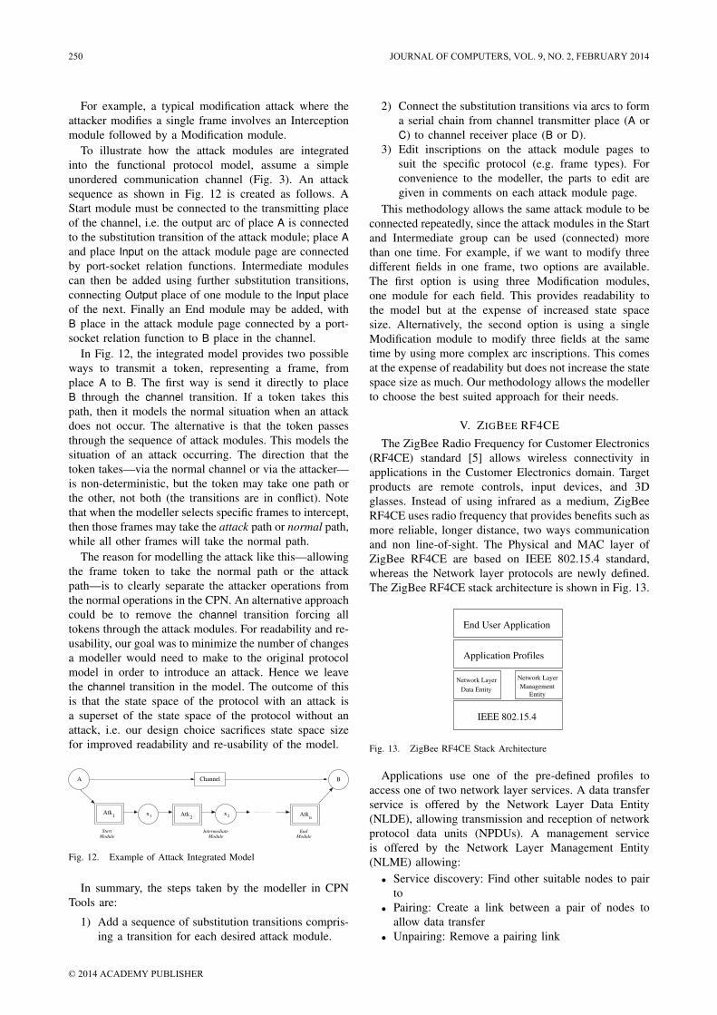
For example, a typical modification attack where theattacker modifies a single frame involves an Interceptionmodule followed by a Modification module.
To illustrate how the attack modules are integratedinto the functional protocol model, assume a simpleunordered communication channel (Fig. 3). An attacksequence as shown in Fig. 12 is created as follows. AStart module must be connected to the transmitting placeof the channel, i.e. the output arc of place A is connectedto the substitution transition of the attack module; place Aand place Input on the attack module page are connectedby port-socket relation functions. Intermediate modulescan then be added using further substitution transitions,connecting Output place of one module to the Input placeof the next. Finally an End module may be added, withB place in the attack module page connected by a port-socket relation function to B place in the channel.
In Fig. 12, the integrated model provides two possibleways to transmit a token, representing a frame, fromplace A to B. The first way is send it directly to placeB through the channel transition. If a token takes thispath, then it models the normal situation when an attackdoes not occur. The alternative is that the token passesthrough the sequence of attack modules. This models thesituation of an attack occurring. The direction that thetoken takes—via the normal channel or via the attacker—is non-deterministic, but the token may take one path orthe other, not both (the transitions are in conflict). Notethat when the modeller selects specific frames to intercept,then those frames may take the attack path or normal path,while all other frames will take the normal path.
The reason for modelling the attack like this—allowingthe frame token to take the normal path or the attackpath—is to clearly separate the attacker operations fromthe normal operations in the CPN. An alternative approachcould be to remove the channel transition forcing alltokens through the attack modules. For readability and re-usability, our goal was to minimize the number of changesa modeller would need to make to the original protocolmodel in order to introduce an attack. Hence we leavethe channel transition in the model. The outcome of thisis that the state space of the protocol with an attack isa superset of the state space of the protocol without anattack, i.e. our design choice sacrifices state space sizefor improved readability and re-usability of the model.
Atk1 x1 Atk
2x2 Atk
n
BChannel
IntermediateModule
A
Module
Start
ModuleEnd
Fig. 12. Example of Attack Integrated Model
In summary, the steps taken by the modeller in CPNTools are:
1) Add a sequence of substitution transitions compris-ing a transition for each desired attack module.
2) Connect the substitution transitions via arcs to forma serial chain from channel transmitter place (A orC) to channel receiver place (B or D).
3) Edit inscriptions on the attack module pages tosuit the specific protocol (e.g. frame types). Forconvenience to the modeller, the parts to edit aregiven in comments on each attack module page.
This methodology allows the same attack module to beconnected repeatedly, since the attack modules in the Startand Intermediate group can be used (connected) morethan one time. For example, if we want to modify threedifferent fields in one frame, two options are available.The first option is using three Modification modules,one module for each field. This provides readability tothe model but at the expense of increased state spacesize. Alternatively, the second option is using a singleModification module to modify three fields at the sametime by using more complex arc inscriptions. This comesat the expense of readability but does not increase the statespace size as much. Our methodology allows the modellerto choose the best suited approach for their needs.
V. ZIGBEE RF4CEThe ZigBee Radio Frequency for Customer Electronics
(RF4CE) standard [5] allows wireless connectivity inapplications in the Customer Electronics domain. Targetproducts are remote controls, input devices, and 3Dglasses. Instead of using infrared as a medium, ZigBeeRF4CE uses radio frequency that provides benefits such asmore reliable, longer distance, two ways communicationand non line-of-sight. The Physical and MAC layer ofZigBee RF4CE are based on IEEE 802.15.4 standard,whereas the Network layer protocols are newly defined.The ZigBee RF4CE stack architecture is shown in Fig. 13.
End User Application
Application Profiles
IEEE 802.15.4
Network Layer
Data Entity
Network Layer
Entity
Management
Fig. 13. ZigBee RF4CE Stack Architecture
Applications use one of the pre-defined profiles toaccess one of two network layer services. A data transferservice is offered by the Network Layer Data Entity(NLDE), allowing transmission and reception of networkprotocol data units (NPDUs). A management serviceis offered by the Network Layer Management Entity(NLME) allowing:• Service discovery: Find other suitable nodes to pair
to• Pairing: Create a link between a pair of nodes to
allow data transfer• Unpairing: Remove a pairing link
250 JOURNAL OF COMPUTERS, VOL. 9, NO. 2, FEBRUARY 2014
© 2014 ACADEMY PUBLISHER

9
• Node initialization: Allow a node to configure itsown stack as a controller node or target node, andstart a network
• NIB attribute manipulation: Manage the NetworkInformation Base (NIB) attribute from the NLME
This case study, and subsequent description, focuseson the pairing mechanism in the NLME. Only featuresrelevant to the modelling/analysis tasks are described; fora full treatment of ZigBee RF4CE see [5].
A. Pairing
Before nodes can communicate with each other apairing link must exist between the two nodes, originatorand recipient. A pairing request is one of the servicespermitted by NLME to create a pairing link betweennodes. The recipient node can choose whether to acceptor reject the pair and confirms the pairing request backto the originator node.
Frames can be sent by a number of transmissionoptions: acknowledged or unacknowledged; unicast orbroadcast; single or multiple channel. In this case studywe assume acknowledged unicast across a single channel.
To communicate between layers of an entity, ZigBeeRF4CE use the concept of service primitives which havefour types; Request, Indication, Response, and Confirm.These primitives are used in many other protocols (e.g.see [21]).
Different command frame types are used in ZigBeeRF4CE. A pair request command frame allows a de-vice to request to pair with another device, while apair response command frame allows a device to re-spond to a pair request and pass information relevant tothe pairing link back to the originator. If the securityis required, the key seed command frame is used toexchange security key seed values with a remote devicein order to generate a security link key. A ping requestcommand frame allows a device to send a ping commandframe to another device and get a response. Similarly,a ping response command frame allows a device torespond to a ping request command frame from anotherdevice.
An example successful pairing attempt with securitysupport, referred to as secure mode, is illustrated inFig. 14. We use this example to explain the typicaloperation of pairing. In this message sequence chart,primitives are shown in normal style while over the aircommand frames are labeled in italic text.
From Fig. 14, the application at the originator issuesa PAIR.request primitive triggering a pair request frameto be sent to the receiver. Upon reception, the NLMEinforms the application on the recipient of the request,which then issues a PAIR.response primitive containingits decision whether to accept or reject the pair. The re-sponse is conveyed to the originator in the pair responseframe with a status field that indicates its decision. Ifrejected (not shown in Fig. 14) a status field is setto NOT PERMITTED and the pairing is terminated. Ifaccepted the status field is set to SUCCESS and as
Application
Originator
(APL−ORG)
Network
Originator
(NWK−ORG) (NWK−REC)
Network
Recipient
(APL−REC)
Application
Recipient
PAIR.request
PAIR.confirm
PAIR.indication
PAIR.response
COMM−STATUS.indication
key_seed(n)
pair_request
key_seed(0)
key_seed(1)
ping_request
ping_response
pair_response
Fig. 14. Message Sequence Chart for Pairing
security is required for pairing (secured mode is in use),the recipient will send a number of key seed frames.Once the originator receives all of the key seed frames,it will generate the security link key and transmit theping request frame encrypted with that key. On receipt ofthe ping request frame, the recipient verifies that frameand sends a ping response frame back to the origi-nator. The originator verifies the ping response frame.PAIR.confirm and COMM.indication primitives are sentto application layer of each side to indicate the status ofpairing. Another alternative configuration of pairing is un-secured mode, where security is not required for pairing,and the process of sending key seed, ping request andping response frames are omitted.
If the pairing was successful, both sides store the entryof the paired side in their respective pairing tables. Eachentry in the pairing table contains all the informationnecessary for the network layer to transmit a frame tothe another side (The format of pairing table is given inTable 49 of [5]).
If a frame is unsuccessfully sent to another side (i.e.timeout occurs or frame errors), the pairing process isstopped and the entry in the pairing table is removed.
VI. CPN MODEL OF PAIRING IN ZIGBEE RF4CETo demonstrate our proposed methodology, a CPN
model of ZigBee RF4CE pairing has been created. Thissection outlines the design of the functional protocolmodel and the integration of two example attacks to formthe security protocol model. Section VII presents analysisresults. All modelling and analysis is performed usingCPN Tools.
A. Model Structure
ZigBee RF4CE is modelled as a hierarchical CPN. TheProtocol page (RF4CE) contains substitution transitions,
JOURNAL OF COMPUTERS, VOL. 9, NO. 2, FEBRUARY 2014 251
© 2014 ACADEMY PUBLISHER

10
which in fact represent a CPN on a sub-page. Thehierarchy is shown in Fig. 15. Two entities of the protocol,ORG (originator) and REC (recipient), are separated inthe second level. Four sub-pages of each entity modeldetail of: passing the primitives between application layerand network layer; managing the network layer processsuch as generating frames and handling timeouts; transmitframes to another entity; and receive frames from anotherentity. In total there are 16 places and 56 transitions.Important declarations used in the model are shown inFig. 16. NWK State and Enumerations are enumeratecolour set used to keep network’s state name and allenumerations (list in Table 45 of [5]), respectively. Coloursets in group SERVICE PRIMITIVES are typed recordand used to record the semantics of primitives listing inSection 3 of [5]. Field, also typed record, is used to recordfield’s values of the command frame showing in Section3.2.2.2 of [5]. The details of key pages are described inSection VI-B.
REC
RF4CE
ORG
ORG_NLME_SAP
ORG_NWK_Process
ORG_Tx_Frame
ORG_Rx_Frame
REC_NLME_SAP
REC_Tx_Frame
REC_NWK_Process
REC_Rx_Frame
Fig. 15. Module Heirarchy of ZigBee RF4CE CPN Model
B. Model Description
Fig. 17 shows the Protocol page of the model, whichillustrates the frame flow between protocol entities. Themodel comprises three main parts: the ORG, the REC anda bidirectional communication medium, Ch1 and Ch2, inthe middle.
a) ORG: The ORG page, shown in Fig. 18, consistsof five places, four substitution transitions and their in-terconnecting arcs. APL ORG and NWK ORG Primitiveplaces are typed by PRIMITIVE colour set and used tostore the service primitives in the application layer and
(*PROTOCOL STATE*)colset NWK State = with idle | pair req sent | pair req sent success | ...
(*ENUMERATIONS*)colset Enumerations = with SUCCESS | NO RESPONSE | ...
(*SERVICE PRIMITIVES*)colset PAIR REQ = record LogicalCh : UNIT ∗ DstIEEEAddr : UNIT ∗ ...colset PAIR IND = record Status : status ∗ SrcPANId : UNIT ∗ ...colset PAIR RES = record Status : status ∗ DstPANId : UNIT ∗ ...colset PAIR CON = record Status : status ∗ PairingRef : INT ∗ ...colset COMM IND = record PairingRef : INT ∗ DstPANId : UNIT ∗ ...
(*NWK CMD FIELD*)colset Field = record ft : FrameType ∗ fc : FrameCounter ∗ ...
(*FRAMES*)colset Entity = with A | B;colset SignKey = STRING;colset EncryptKey = STRING;colset Frame = record sender : Entity ∗ receiver : Entity ∗ field : Field ∗ ...colset Frames = list Frame;
Fig. 16. Selected ZigBee RF4CE Declarations
nwkQ4
nwkQ4^^[f]
nwkQ3
f::nwkQ3
nwkQ2
nwkQ2^^[f]
nwkQ1
f::nwkQ1
RECRECORGORG
Ch2
Ch1
D
1`[]
Frames
C
1`[]
Frames
B
1`[]
Frames
A
1`[]
Frames
ORGREC
Fig. 17. Protocol page of ZigBee RF4CE CPN Model
the network layer, respectively. The APL ORG place hasan initial marking of one PAIR REQ token, indicating thatthe originator is ready to start the pairing request service.The NWK ORG Frame place stores command frames,which is either the frames to be sent to the recipientthrough place A or the frames to be received from therecipient through place C. These places are typed byFrames colour set and has an initial marking of an emptylist (1‘[]).
ORG NLME SAP substitution transition models thetransmission and reception of service primitives betweenapplication layer and network layer. ORG NWK Processsubstitution transition models the internal mechanism ofthe network layer, i.e. checking the capacity of pairingtable, generating network command frames, and handlingtimeouts. ORG Tx Frame and ORG Rx Frame substi-tution transitions model the transmission and receptionof the network command frames to/from the recipiententity. In the ORG NWK Process, ORG Tx Frame, andORG Rx Frame substitution transitions, there are twoadditional places: NWK ORG PT represents the stateof pairing table; and NWK ORG STATE represents thecurrent state of the protocol.
C
I/OFrames
1`[]
Frames
PRIMITIVE
1`PAIR_REQ(Gen_PAIR_REQ())
PRIMITIVE
A
I/OFrames
I/OI/O
ORG_Rx_Frame
ORG Rx FrameORG Rx Frame
ORG_Tx_Frame
ORG Tx FrameORG Tx Frame
NWK_ORG_Frame
ORG_NWK_Process
ORG NWK ProcessORG NWK Process
NWK_ORG_Primitive
ORG_NLME_SAP
ORG NLME SAPORG NLME SAP
APL_ORG
Fig. 18. ORG Page of ZigBee RF4CE CPN Model
252 JOURNAL OF COMPUTERS, VOL. 9, NO. 2, FEBRUARY 2014
© 2014 ACADEMY PUBLISHER

11
b) REC: For the recipient side, the mechanism ofplaces and substitution transitions are similar to the orig-inator side but changes the label from ORG to REC.
c) Communication Medium: The underlying com-munication medium is modelled as a bidirectional channelwith FIFO queue consisting of four places: A; B; C; andD, and two transitions: Ch1 and Ch2. The communicationchannels allow frames to be lost. The loss behaviourcan correspond to either loss in the network (due to thecongestion in the network), or to discarding the framesdue to the checksum failure.
C. Model with Attacks
After a protocol model is created, the protocol modellercan choose the attack modules from library and integratethem into communication channel in both directions. Weillustrate two example attacks in this section.
1) One Way Attack: The first example illustrates anattack that occurs in one direction (recipient to originator).Between the pairing process an attacker tries to intercept apair response frame from a recipient and then modify thestatus field from SUCCESS to NOT PERMITTED (thisstatus field is sent when the recipient does not want toaccept the pair). Thereby the originator believes that therecipient does not accept the pairing request and then bothsides are not synchronized at the end of pairing process.
This example one way attack is implemented usingthree attack modules: Interception, Modification, and In-jection. These modules are integrated into the ZigBeeRF4CE functional protocol model at the communicationchannel (Ch2 part) as shown in Fig. 19.
nwkQ4
nwkQ4^^[f] f::nwkQ3
nwkQ3
InjectInjection ModifyModification InterceptInterception
Ch2
y
UNIT
x
UNIT
C
I/O
1`[]
Frames
D
I/O
1`[]
FramesI/OI/O
Injection InterceptionModification
Fig. 19. One Way Attack
The modeller must perform three steps to integrate theattack modules:
1) Connect the modules together via their Input andOutput places, as well as to the communicationchannel places. For example, in Modification, theInput and Output places of this module are con-nected with x and y places of the communicationchannel (Ch2) subpage by a port-socket relationfunction, respectively.
2) Change arc inscriptions of the modules to suit thespecific protocol following the given instructions inthe attack module page.
3) Optionally, specify the initial marking of the Filterplace in each module to apply the module on onlyselected frames. For example, in the Modificationmodule the initial marking is set to 1‘Pair responseas only modification of pair response frames areconsidered in this attack.
These three attack modules are applied to model theattack that describe above. As an example, the detailof Modification module which integrated in Fig. 19 isshown in Fig. 20. The Input place and Output placeof this attack module are linked with x and y places,respectively. The Filter place has colour set of type Com-mandIdentifier since the attacker wants to modify only thepair response frame, so this place has an initial markingof 1‘Pair response and it will be filtered by a guard atSelect transition. After frame selection only the selectedframe, pair response, will modify at the Modify transition,with the modified frame stored in the After place.
1`()
fff
cmd
ModifySelectFrame
UNITUNIT
To beModify
Frame
1`Pair_response
CommandIdentifier
Frame
[#cmd_id (#field f) = cmd]
Before
Attacker DBAttacker DB
After
Attacker DBAttacker DB
Filter
1`()
Input
InIn
Output
OutOutFrame.set_field f {ft=(#ft (#field f)),fc=(#fc (#field f)),cmd_id=(#cmd_id (#field f)),status=NOT_PERMITTED,key=(#key (#field f)),mic=(#mic (#field f))}
Fig. 20. Modification Module in One Way Attack
2) Two Ways Attack: The second example illustrates anattack that occurs in both directions of the communicationchannel. In this attack the attacker wants the originator toremove the recipient’s entry in a pairing table due to thepair response frame being lost (dropped by the attacker).Meanwhile the attacker also wants the recipient to believethat the pair response frame arrives at the originator sideperfectly. By doing this at the end of pairing process theoriginator and the recipient are not synchronized.
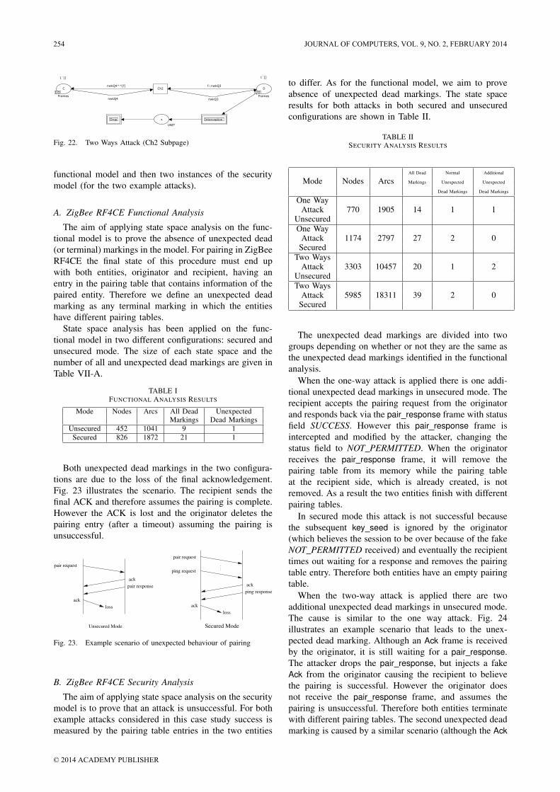
There are two steps for this attack, as shown inFig. 21 and Fig. 22. The attacker can achieve the goalby intercepting and dropping a pair response frame fromthe recipient entity. This attack sequence is shown inFig. 22. After that the attacker will intercept a newpair request frame from the originator entity, generatea bogus acknowledgement frame and inject it to therecipient side. This is shown in Fig. 21.
To control the state space size (not to lead to infinitesize of state space), the number of a generated bogusacknowledgement frame will be limited from the Limitplace in Generation module by putting the initial markingof one in the Limit place.
nwkQ2
nwkQ2^^[f]f::nwkQ1
nwkQ1
InjectionInjectionMSG GenerationMSG Generation
Ch1
yy
UNIT
xx
UNIT
B
I/O
1`[]
Frames
A
I/O
1`[]
FramesI/O I/O
InjectionMSG GenerationInterceptionInterceptionInterception
Fig. 21. Two Ways Attack (Ch1 Subpage)
VII. ANALYSIS OF ZIGBEE RF4CE
Calculating the state space of a CPN model allowsfor proof of properties of the model. In this section weshow results from applying state space analysis of first the
JOURNAL OF COMPUTERS, VOL. 9, NO. 2, FEBRUARY 2014 253
© 2014 ACADEMY PUBLISHER
12
nwkQ4^^[f] f::nwkQ3Ch2
UNIT
C
I/O
1`[]
Frames
D
I/O
1`[]
FramesI/OI/O
nwkQ3nwkQ4
InterceptInterceptionInterceptionxDropDropDrop
Fig. 22. Two Ways Attack (Ch2 Subpage)
functional model and then two instances of the securitymodel (for the two example attacks).
A. ZigBee RF4CE Functional Analysis
The aim of applying state space analysis on the func-tional model is to prove the absence of unexpected dead(or terminal) markings in the model. For pairing in ZigBeeRF4CE the final state of this procedure must end upwith both entities, originator and recipient, having anentry in the pairing table that contains information of thepaired entity. Therefore we define an unexpected deadmarking as any terminal marking in which the entitieshave different pairing tables.
State space analysis has been applied on the func-tional model in two different configurations: secured andunsecured mode. The size of each state space and thenumber of all and unexpected dead markings are given inTable VII-A.
TABLE IFUNCTIONAL ANALYSIS RESULTS
Mode Nodes Arcs All Dead UnexpectedMarkings Dead Markings
Unsecured 452 1041 9 1Secured 826 1872 21 1
Both unexpected dead markings in the two configura-tions are due to the loss of the final acknowledgement.Fig. 23 illustrates the scenario. The recipient sends thefinal ACK and therefore assumes the pairing is complete.However the ACK is lost and the originator deletes thepairing entry (after a timeout) assuming the pairing isunsuccessful.
pair request
ack
pair response
ack
ping request
ack
ack
ping response
pair request
loss
loss
Unsecured Mode Secured Mode
Fig. 23. Example scenario of unexpected behaviour of pairing
B. ZigBee RF4CE Security Analysis
The aim of applying state space analysis on the securitymodel is to prove that an attack is unsuccessful. For bothexample attacks considered in this case study success ismeasured by the pairing table entries in the two entities
to differ. As for the functional model, we aim to proveabsence of unexpected dead markings. The state spaceresults for both attacks in both secured and unsecuredconfigurations are shown in Table II.
TABLE IISECURITY ANALYSIS RESULTS
All Dead Normal Additional
Mode Nodes Arcs Markings Unexpected Unexpected
Dead Markings Dead Markings
One WayAttack 770 1905 14 1 1
UnsecuredOne Way
Attack 1174 2797 27 2 0Secured
Two WaysAttack 3303 10457 20 1 2
UnsecuredTwo Ways
Attack 5985 18311 39 2 0Secured
The unexpected dead markings are divided into twogroups depending on whether or not they are the same asthe unexpected dead markings identified in the functionalanalysis.
When the one-way attack is applied there is one addi-tional unexpected dead markings in unsecured mode. Therecipient accepts the pairing request from the originatorand responds back via the pair response frame with statusfield SUCCESS. However this pair response frame isintercepted and modified by the attacker, changing thestatus field to NOT PERMITTED. When the originatorreceives the pair response frame, it will remove thepairing table from its memory while the pairing tableat the recipient side, which is already created, is notremoved. As a result the two entities finish with differentpairing tables.
In secured mode this attack is not successful becausethe subsequent key seed is ignored by the originator(which believes the session to be over because of the fakeNOT PERMITTED received) and eventually the recipienttimes out waiting for a response and removes the pairingtable entry. Therefore both entities have an empty pairingtable.
When the two-way attack is applied there are twoadditional unexpected dead markings in unsecured mode.The cause is similar to the one way attack. Fig. 24illustrates an example scenario that leads to the unex-pected dead marking. Although an Ack frame is receivedby the originator, it is still waiting for a pair response.The attacker drops the pair response, but injects a fakeAck from the originator causing the recipient to believethe pairing is successful. However the originator doesnot receive the pair response frame, and assumes thepairing is unsuccessful. Therefore both entities terminatewith different pairing tables. The second unexpected deadmarking is caused by a similar scenario (although the Ack
254 JOURNAL OF COMPUTERS, VOL. 9, NO. 2, FEBRUARY 2014
© 2014 ACADEMY PUBLISHER

13
frame is received by the originator after a timeout).
pair request
ack
pair responsedrop
fake acktimeout
Fig. 24. Example scenario of unexpected behaviour in Two WaysAttack
In secured mode this attack is not successful because,as with the one-way attack, the key seed is ignored by theoriginator. Hence the recipient will not receive a response,and eventually remove the pairing table entry.
C. Discussion
This case study has shown how to apply our method-ology to incorporate attacks into a functional protocolmodel. Although the case study focusses on a small partof a ZigBee RF4CE it demonstrates attacks can be easilyintegrated and functional and security analysis conductedon the model state space.
The results obtained from the functional analysis inSection VII-A illustrate that problems occur in ZigBee ifthe final acknowledgement frame is lost. This problem isnot unique to ZigBee it can occur in many protocols,and is related to the Byzantine General’s problem. InZigBee it is likely that the error will be detected in phasessubsequent to pairing. For example, if one entity belivesthe pairing is successful, while the other does not, thencommunications in subsequent phases will result in anerror, and the pairing should be cancelled.
For the result in Section VII-B, which come from thesecurity analysis of protocol, at this time there are noknown papers or discussion related in ZigBee RF4CE thatmention this weakness of the protocols when two entitiesare not synchronized at the end of the pairing processwhich caused from the attacker. Hence we believe this isa valuable result from our analysis.
Note the size of the state space without attacks is up to826 nodes (secured mode), while introducing the attacksincreases the state space to 5985 nodes (secured mode,two-way attack). Although the number of nodes is smallin both cases (CPN Tools may handle a million nodes)there is still a seven-fold increase from introducing anattack. To investigate the impact of our proposed Filterplace to limit the state space increase, we have calculatedthe state space for the case when they are not used (theLimit place is set to one, cannot be removed since itwill generate infinite size of state space). The numberof nodes is 13789 nodes. By using the Filter and Limitplaces the state space is reduced by a factor of 2.3.Although they require the modeller to make assumptionsabout the attack, the implementation of Filter and Limitin our methodology delivers a valuable reduction in thestate space size. Restricting some kinds of frames leads to
smaller state space size, at the expense of fewer securityattacks analysed. The value of restricting frames dependson the protocol under consideration and the goal of themodeller. There is no one answer in the end the modellermust decide. Our methodology includes the mechanismsto allow the modeller to easily choose one (more attacksor smaller state space). However it should be noted thatmore many non-trivial protocols, state space size often isa limiting factor of formal analysis, especially with CPNs.
Further demonstrations of the methodology are neededto evaluate the benefits to the modeller. Although notreported in this paper, we have applied the methodologyon the Andrew RPC protocol, which was also used asan example in the methodology developed in [16]. Ouranalysis produced the same results as reported in [16](and originally in [22]). Further case studies are plannedin the future.
VIII. CONCLUSION
The purpose of this research is to overcome the limita-tions of the traditional security analysis techniques, in par-ticular making it possible to protocol designers/modellersto perform security analysis without expert knowledge inthe analysis techniques. We achieve this by presenting anovel methodology using Coloured Petri nets that offersa graphical modelling language, a library of commonsecurity attack modules and automatic property verifi-cation (through state space analysis). The methodologyis developed so that models of communication proto-cols and attacks are re-usable, extendable and readable.The library of attack modules developed can be easilycomposed to form more complex attacks specific to aprotocol. Although a modeller using our methodologyrequires knowledge of security techniques to create anattack model, by using our library of modules they canreduce the time to develop the model. To demonstratethe methodology we apply it to a part of the ZigBeeRF4CE protocol (i.e. pairing). Analysis in the presenceof two separate attacks reveals unexpected dead markingsare caused by the attacks.
In addition to further case studies there are severalareas to extend our research. Currently the attack modulesare designed for readability, but lead to increased statespace sizes. We will consider alternative, more compactmodels and compare how much they impact on statespace size. Then we will extend our methodology to covermore general protocols, in particular multi-party protocols(e.g. routing protocols; key distribution with trusted-thirdparties).
IX. ACKNOWLEDGEMENT
The authors are grateful to the anonymous referees fortheir valuable comments and suggestions to improve thepresentation of this paper.
REFERENCES
[1] K. Jensen and L. M. Kristensen, Coloured Petri Nets: Modellingand Validation of Concurrent Systems. Springer, 2009.
JOURNAL OF COMPUTERS, VOL. 9, NO. 2, FEBRUARY 2014 255
© 2014 ACADEMY PUBLISHER

14
[2] C. Meadows, “Formal methods for cryptographic protocol analy-sis: Emerging issues and trends,” IEEE Journal on Selected Areasin Communications, vol. 21, no. 1, pp. 44–54, January 2003.
[3] I. Al-Azzoni, Douglas G. Down and R. Khedri, “Modeling andverification of cryptographic protocols using Coloured Petri netsand design/cpn,” Nordic Journal of Computing, vol. 12, no. 3, pp.201–228, June 2005.
[4] S. Long, “Analysis of concurrent security protocols using ColoredPetri nets,” in Proceedings of International Conference on Net-working and Digital Society, 2009, pp. 227–230.
[5] ZigBee RF4CE Specification Version 1.00, ZigBee Alliance, March2009.
[6] F. Babich and L. Deotto, “Formal methods for specificationand analysis of communication protocols,” IEEE CommunicationsSurveys & Tutorials, vol. 4, no. 1, pp. 2–20, First quarter 2002.
[7] Department of Computer Science, University of Aarhus, “CPNTools,” Web site: http://wiki.daimi.au.dk/cpntools/.
[8] S. Gordon, L. M. Kristensen and J. Billington, “Verification on arevised WAP wireless transaction protocol,” in Proceedings of theInternational Conference on Application and Theory of Petri Nets,Adelaide, Australia, June 2002, pp. 182–202.
[9] L. Liu and J. Billington, “Verification of the capability exchangesignalling protocol,” International Journal on Software Tools forTechnology Transfer, vol. 9, no. 3-4, pp. 305–326, June 2007.
[10] S. Suriadi, C. Ouyang, J. Smith and E. Foo, “Modeling andverification of privacy enhancing protocols,” in Proceedings of the11th International Conference of Formal Engineering Methods:Formal Methods and Software Engineering, 2009, pp. 127–146.
[11] S. Gordon and S. Choosang, “Verification of the FlexRay transportprotocol for autosar in-vehicle communications,” InternationalJournal of Vehicular Technology, vol. 2010, 2010.
[12] F. Erbas, K. Kyamakya and K. Jobmann, “Modelling and per-formance analysis of a novel position-based reliable unicast andmulticast routing method using Coloured Petri nets,” in Proceed-ings of the 58th IEEE Vehicular Technology Conference, October2003, pp. 3099–3104.
[13] L. zhang Zhu and H. Zhang, “Queuing network models analysisbased on CPN,” in Proceedings of the 2nd International Confer-ence on Information and Computing Science, May 2009, pp. 269–272.
[14] S. Korecko, B. Sobota and C. Szabo, “Performance analysis ofprocesses by automated simulation of Coloured Petri nets,” inProceedings of the 10th International Conference on IntelligentSystems Design and Applications, November 2010, pp. 176–181.
[15] L. Liu, “Uncovering SIP vulnerabilities to DoS attacks usingColoured Petri nets,” in Proceedings of the 10th IEEE InternationalConference on Trust, Security and Privacy in Computing andCommunications, 2011, pp. 29–36.
[16] Y. Xu and X. Xie, “Modeling and analysis of security protocolsusing Coloured Petri nets,” Journal of Computers, vol. 6, no. 1,pp. 19–27, January 2011.
[17] Y. Permpoontanalarp, “On-the-fly trace generation and textualtrace analysis and their applications to the analysis of crypto-graphic protocols,” in Proceedings of the 30th Formal Techniquesfor Networked and Distributed Systems, Amsterdam, June 2010.
[18] Y. Permpoontanalarp and P. Sornkhom, “A new Coloured Petri netmethodology for the security analysis of cryptographic protocols,”in Proceedings of the 10th Workshop and Tutorial on PracticalUse of Coloured Petri Nets and the CPN Tools, Aarhus, Denmark,October 2009.
[19] J. Billington, G. E. Gallasch, and B. Han, “A Coloured Petri netapproach to protocol verification,” in Lectures on Concurrency andPetri Nets, Advances in Petri Nets. Springer-Verlag, 2004, pp.210–290.
[20] D. Dolev and A. Yao, “On the security of public key protocols,”IEEE Transactions on Information Theory, vol. 29, no. 2, pp. 198–208, March 1983.
[21] David E. Carlson, “ANSI/IEEE 802.2, 1998 edition.”[22] G. Lowe, “Some new attacks upon security protocols,” in Proceed-
ings of the 9th IEEE Workshop Computer Security Foundations,1996, pp. 162–169.
San Choosang received a B.Sc. in computerscience from Sirindhorn International Instituteof Technology, Thammasat University, 2010,Thailand. He has been a Certified Cisco Sys-tem Instructor at the Network Training Cen-ter Co.,Ltd., Thailand. He is currently a M.Sstudent in Sirindhorn International Instituteof Technology, Thammasat University, Thai-land. His research interests include: computernetworking; formal analysis of protocols andInternet security protocols.
Steven Gordon obtained a Ph.D. in Telecom-munications from the University of South Aus-tralia in 2001. He worked as a senior re-searcher at the Institute for Telecommunica-tions Research, UniSA, up until 2006. Hehas since been with Thammasat University,Thailand, currently as an Associate Profes-sor within Sirindhorn International Institute ofTechnology. His research interests includes:formal analysis of protocols; integration of IP-based mobile networks with ad hoc networks;
design of wireless networks for QoS guarantees; Internet and mobilepeer-to-peer protocols; and Internet security protocols. He serves onthe editorial board and TPC of various international journals andconferences. He is a member of IEEE, ACM and IEICE.
256 JOURNAL OF COMPUTERS, VOL. 9, NO. 2, FEBRUARY 2014
© 2014 ACADEMY PUBLISHER