a. commercial freezer, refrigerator … : basf1/basf2/basf3(freezer) basr1/basr2/basr3(refrigerator)...
TRANSCRIPT

■ MODEL : BASF1/BASF2/BASF3(FREEZER) BASR1/BASR2/BASR3(REFRIGERATOR)
BAGR24/BAGR48/BAGR72 (MERCHANDISERS)
A. COMMERCIAL FREEZER, REFRIGERATOR GENERAL
1. SPECIFICATION - - - - - - - - - - - - - - - - - - - - - - A2
1) GENERAL
2) MAIN COMPONENTS
2. REFRIGERATION CYCLE - - - - - - - - - - - - - - - - - - - A6
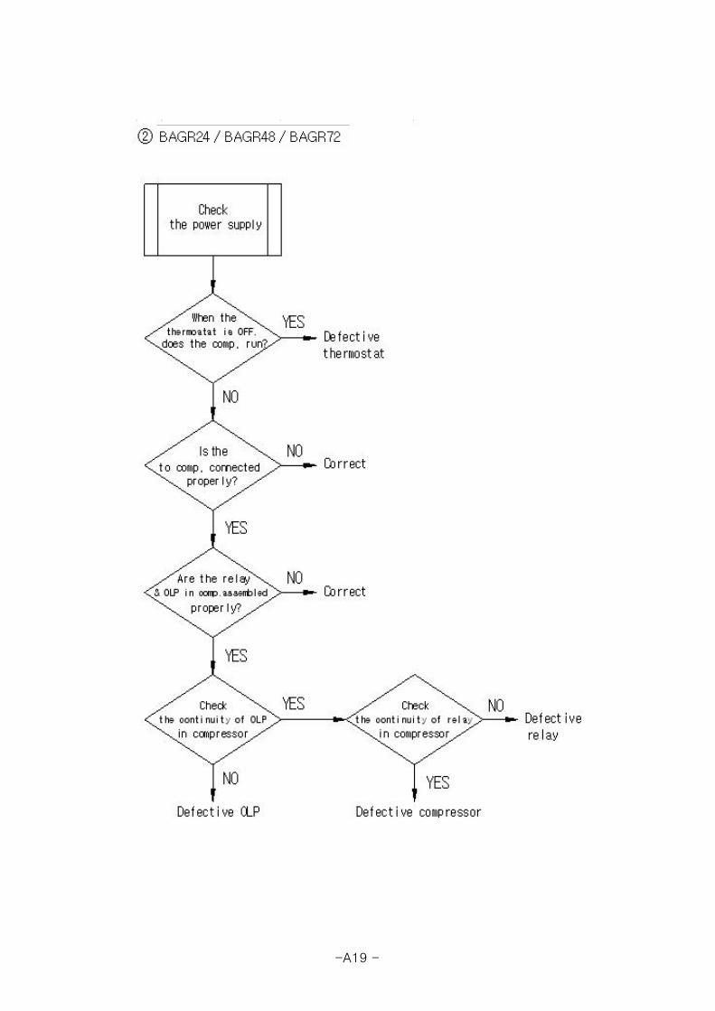
3. TROUBLE SHOOTING - - - - - - - - - - - - - - - - - - - - - A8
1) CHECKING THE POWER SUPPLY
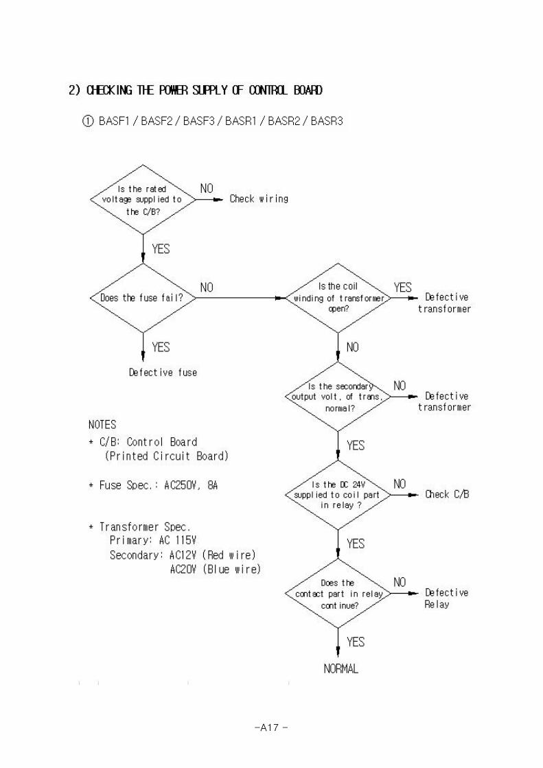
2) CHECKING THE POWER SUPPLY OF CONTROL BOARD
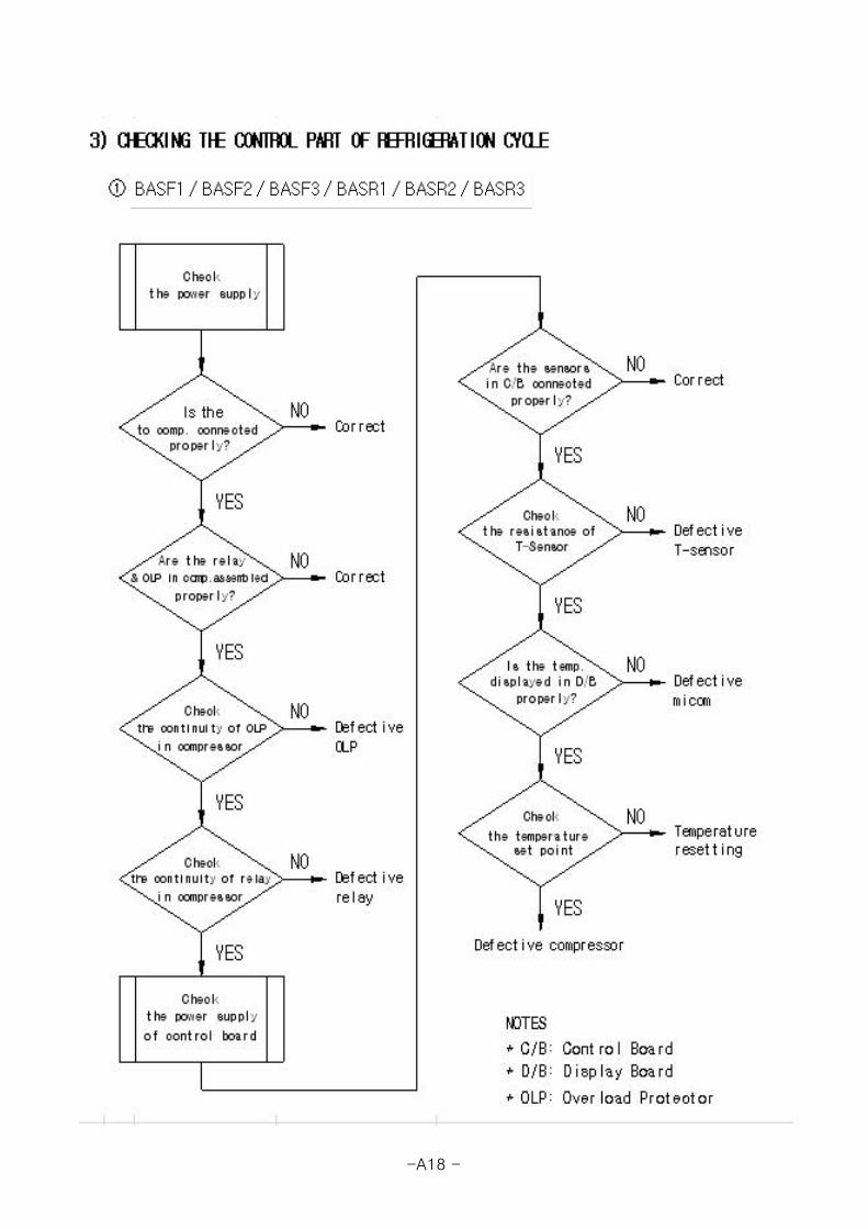
3) CHECKING THE CONTROL PART OF REFRIGERATION CYCLE
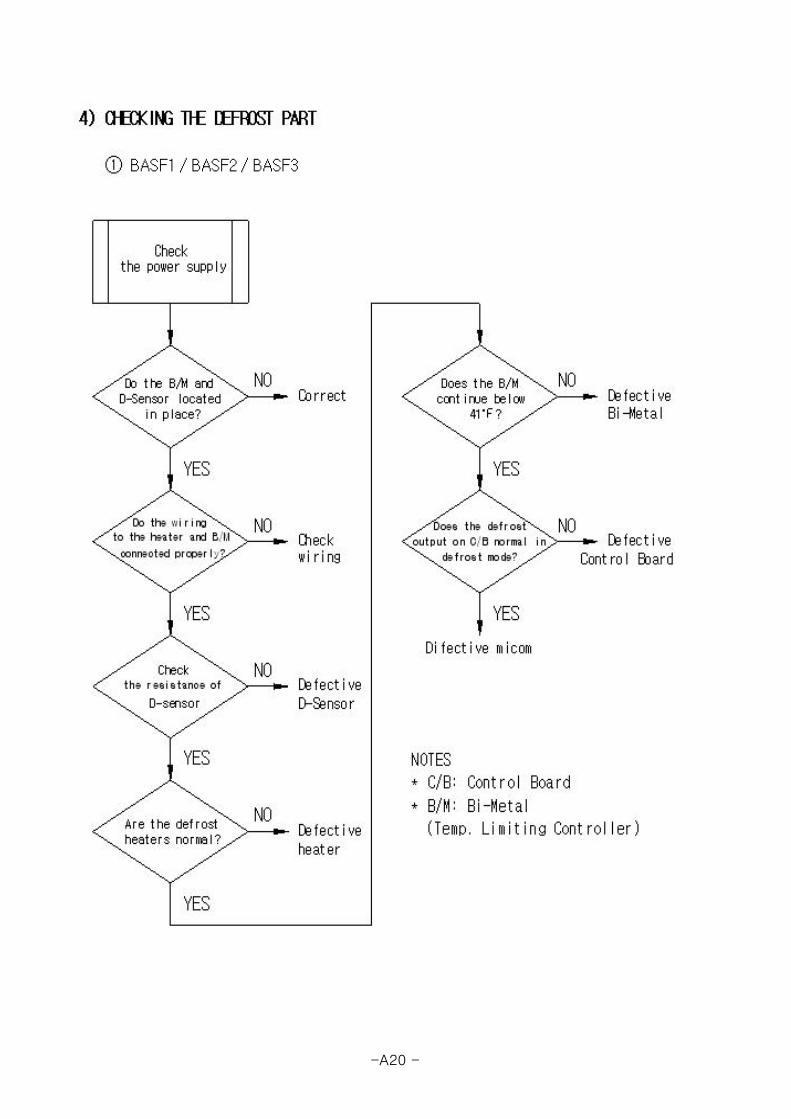
4) CHECKING THE DEFROST PART
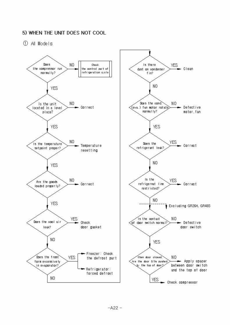
5) WHEN THE UNIT DOES NOT COOL
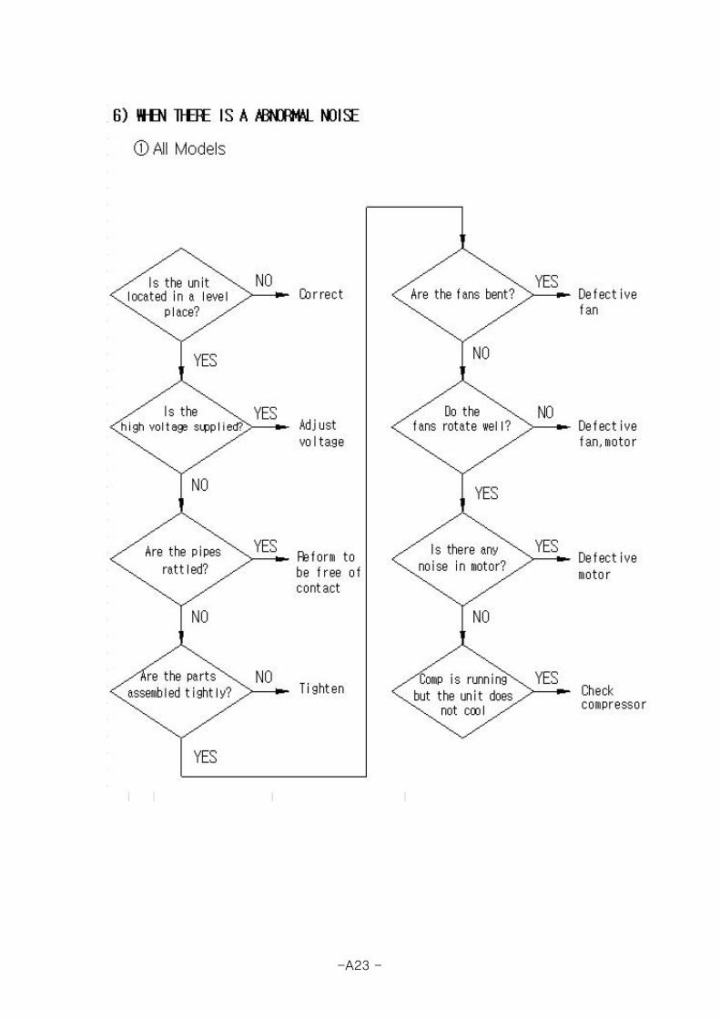
6) WHEN THERE IS A ABNORMAL NOISE
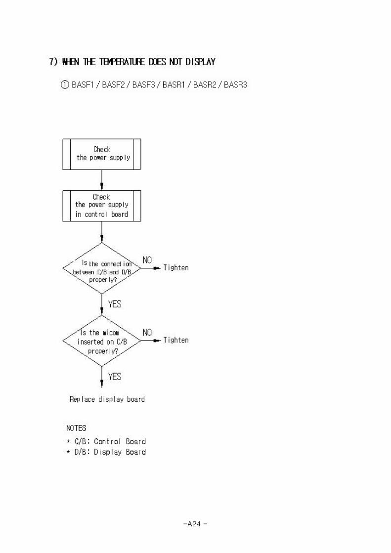
7) WHE THE TEMPERATURE DOES NOT DISPLAY
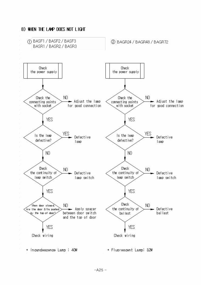
8) WHEN THE LAMP DOES NOT LIGHT
9) CHECKING SENSOR
4. FEATURE CHART - - - - - - - - - - - - - - - - - - - - - - - A18
5. WIRING DIAGRAM - - - - - - - - - - - - - - - - - - - - - - A30
6. REPLACEMENT OF COMPONENTS - - - - - - - - - - - - - - - - - A35
-A1 -

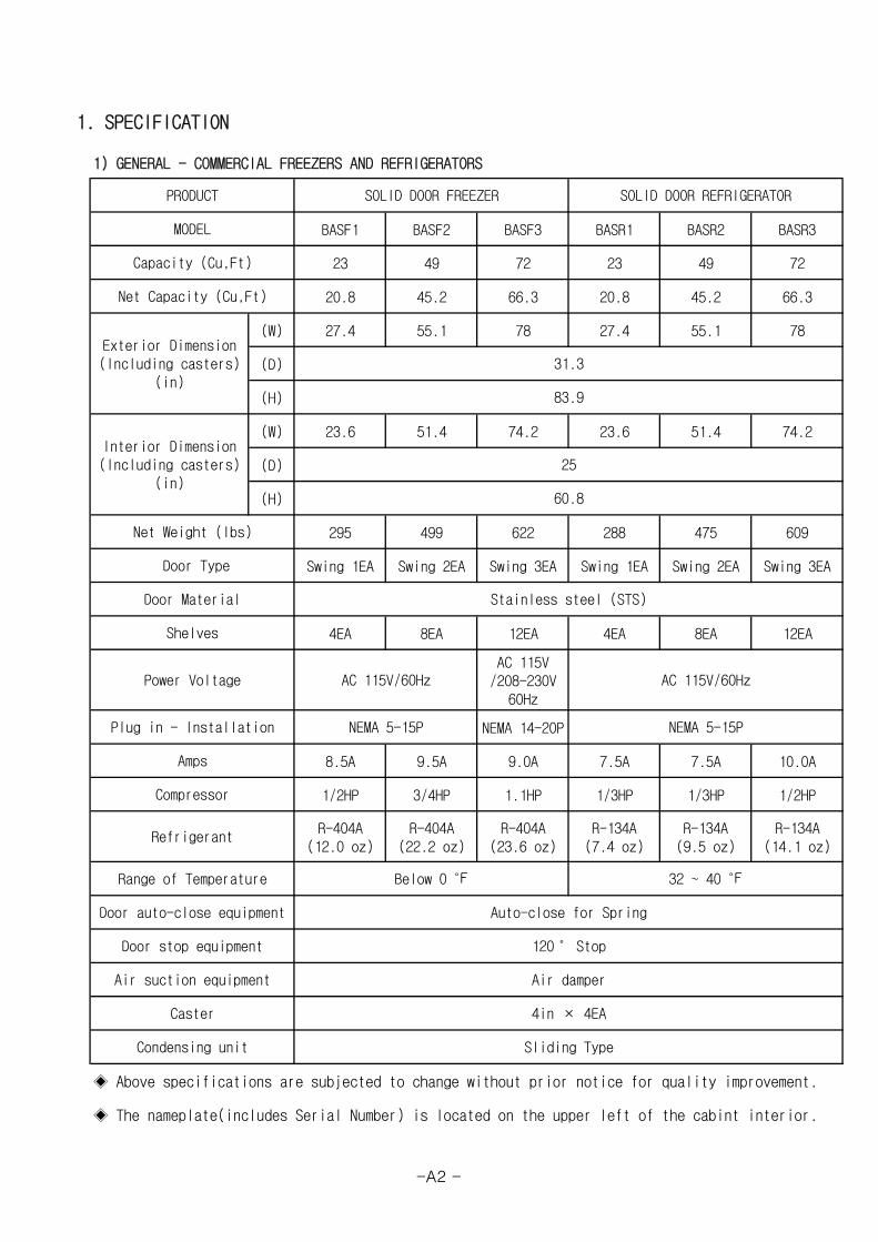
1. SPECIFICATION
1) GENERAL - COMMERCIAL FREEZERS AND REFRIGERATORS
BASF1 BASF2 BASF3 BASR1 BASR2 BASR3
23 49 72 23 49 72
20.8 45.2 66.3 20.8 45.2 66.3
(W) 27.4 55.1 78 27.4 55.1 78
(D)
(H)
(W) 23.6 51.4 74.2 23.6 51.4 74.2
(D)
(H)
295 499 622 288 475 609
Swing 1EA Swing 2EA Swing 3EA Swing 1EA Swing 2EA Swing 3EA
4EA 8EA 12EA 4EA 8EA 12EA
AC 115V/208-230V
60Hz
NEMA 14-20P
8.5A 9.5A 9.0A 7.5A 7.5A 10.0A
1/2HP 3/4HP 1.1HP 1/3HP 1/3HP 1/2HP
R-404A(12.0 oz)
R-404A(22.2 oz)
R-404A(23.6 oz)
R-134A(7.4 oz)
R-134A(9.5 oz)
R-134A(14.1 oz)
◈ Above specifications are subjected to change without prior notice for quality improvement.
◈ The nameplate(includes Serial Number) is located on the upper left of the cabint interior.
Sliding Type
32 ~ 40 ℉
Auto-close for Spring
25
60.8
Stainless steel (STS)
AC 115V/60Hz
NEMA 5-15P
Below 0 ℉
AC 115V/60Hz
NEMA 5-15P
Air damper
4in × 4EACaster
Condensing unit
Capacity (Cu,Ft)
Net Capacity (Cu,Ft)
Net Weight (lbs)
Interior Dimension(Including casters)
(in)
Door Type
Shelves
Power Voltage
PRODUCT
MODEL
SOLID DOOR FREEZER
Door Material
31.3
83.9
Exterior Dimension(Including casters)
(in)
SOLID DOOR REFRIGERATOR
Amps
Refrigerant
120˚ Stop
Compressor
Plug in - Installation
Range of Temperature
Door auto-close equipment
Door stop equipment
Air suction equipment
-A2 -

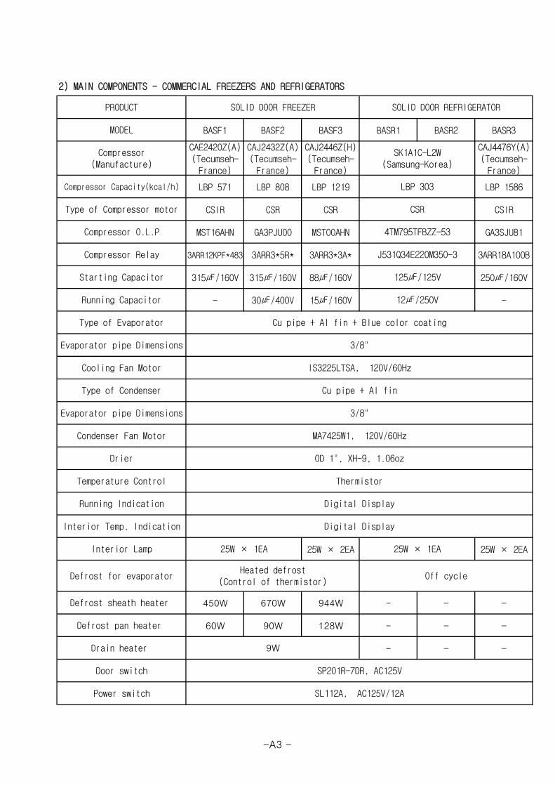
2) MAIN COMPONENTS - COMMERCIAL FREEZERS AND REFRIGERATORS
BASF1 BASF2 BASF3 BASR1 BASR2 BASR3
CAE2420Z(A)(Tecumseh-France)
CAJ2432Z(A)(Tecumseh-France)
CAJ2446Z(H)(Tecumseh-France)
CAJ4476Y(A)(Tecumseh-France)
LBP 571 LBP 808 LBP 1219 LBP 1586
CSIR CSR CSR CSIR
MST16AHN GA3PJU00 MST00AHN GA3SJU81
3ARR12KPF*483 3ARR3*5R* 3ARR3*3A* 3ARR18A100B
315㎌/160V 315㎌/160V 88㎌/160V 250㎌/160V
- 30㎌/400V 15㎌/160V -
25W × 2EA 25W × 2EA
450W 670W 944W - - -
60W 90W 128W - - -
- - -
Digital Display
25W × 1EA 25W × 1EA
Heated defrost(Control of thermistor)
Off cycle
9W
SP201R-7DR, AC125V
SL112A, AC125V/12A
SOLID DOOR FREEZER SOLID DOOR REFRIGERATOR
Cu pipe + Al fin + Blue color coating
4TM795TFBZZ-53
J531Q34E220M350-3
125㎌/125V
CSR
SK1A1C-L2W(Samsung-Korea)
Type of Compressor motor
Compressor O.L.P
Compressor Relay
Type of Evaporator
Cu pipe + Al fin
3/8"
LBP 303
PRODUCT
IS3225LTSA, 120V/60Hz
Evaporator pipe Dimensions
Type of Condenser
Drier
MA7425W1, 120V/60Hz
Defrost for evaporator
Defrost pan heater
Drain heater
Door switch
Power switch
Digital DisplayRunning Indication
OD 1", XH-9, 1.06oz
Condenser Fan Motor
Defrost sheath heater
Interior Lamp
Temperature Control Thermistor
12㎌/250V
3/8"
MODEL
Compressor(Manufacture)
Compressor Capacity(kcal/h)
Starting Capacitor
Running Capacitor
Interior Temp. Indication
Evaporator pipe Dimensions
Cooling Fan Motor
-A3 -
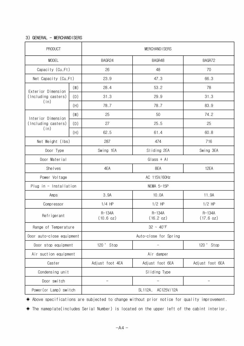
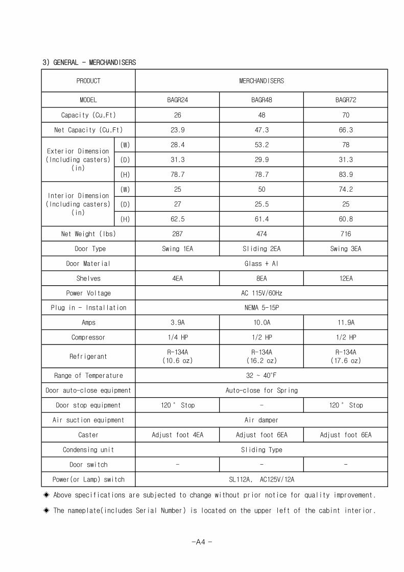
3) GENERAL - MERCHANDISERS
(W)
(D)
(H)
(W)
(D)
(H)
◈ Above specifications are subjected to change without prior notice for quality improvement.
◈ The nameplate(includes Serial Number) is located on the upper left of the cabint interior.
R-134A(16.2 oz)
R-134A(17.6 oz)
-
SL112A, AC125V/12A
120˚ Stop
Sliding Type
-
Swing 1EA Sliding 2EA
32 ~ 40℉
Auto-close for Spring
1/4 HP 1/2 HP
60.8
4EA 8EA
62.5
287 474 716
Glass + Al
74.2
11.9A
12EA
25.5
Swing 3EA
47.3
78
31.3
83.9
MERCHANDISERS
BAGR24 BAGR48
26 48 70
BAGR72
PRODUCT
MODEL
Door switch
66.3
50
78.7
53.2
25
29.9
78.7
28.4
31.3
23.9
Compressor
61.4
2527
Amps
1/2 HP
10.0A
AC 115V/60Hz
NEMA 5-15P
3.9A
-
Net Capacity (Cu,Ft)
Interior Dimension(Including casters)
(in)
Power(or Lamp) switch
Refrigerant
Range of Temperature
Power Voltage
Plug in - Installation
Condensing unit
Adjust foot 4EA
Door auto-close equipment
Door stop equipment
Air damper
Adjust foot 6EA
Air suction equipment
Adjust foot 6EACaster
120˚ Stop -
R-134A(10.6 oz)
Exterior Dimension(Including casters)
(in)
Capacity (Cu,Ft)
Shelves
Door Type
Door Material
Net Weight (lbs)
-A4 -

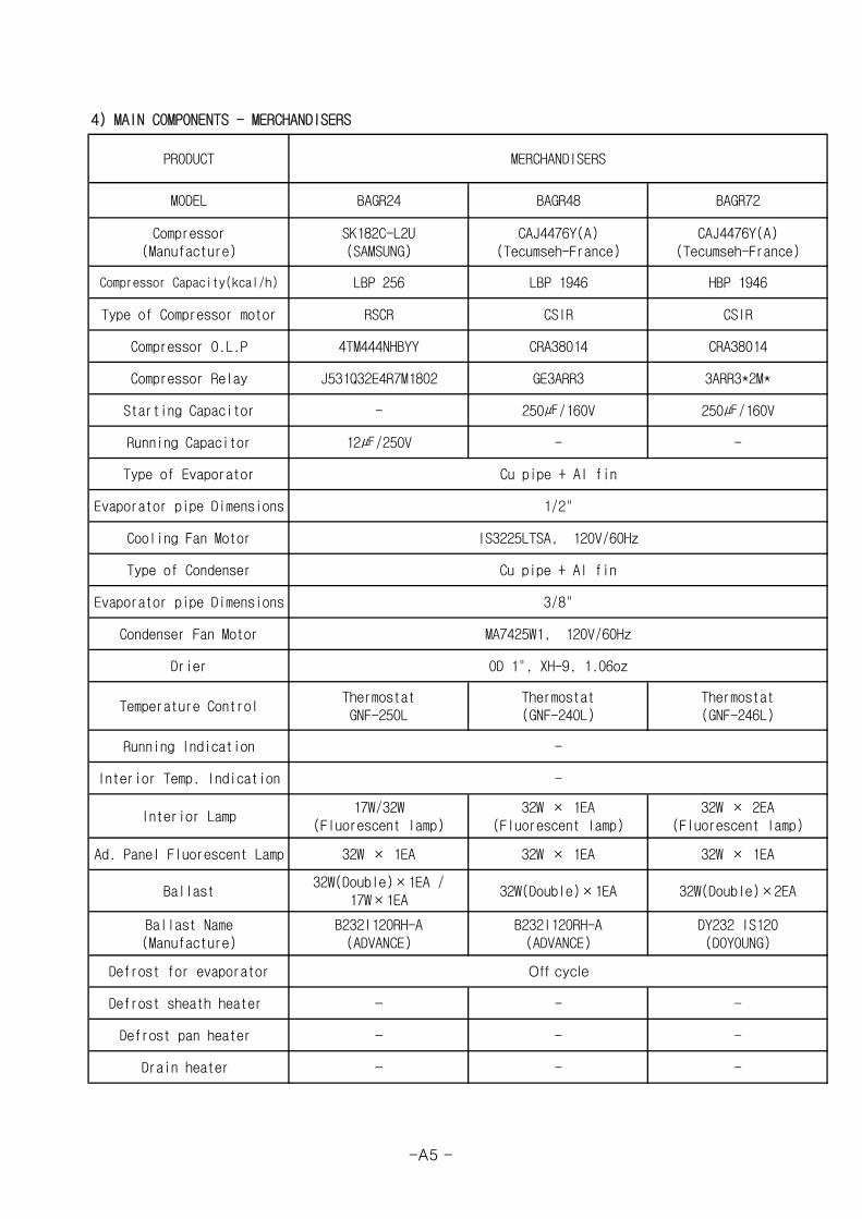
4) MAIN COMPONENTS - MERCHANDISERS
-
-
-
-
-
-
-
-
-
250㎌/160V
-
DY232 IS120(DOYOUNG)
32W × 1EA(Fluorescent lamp)
32W × 1EA
32W(Double)×1EA
-
IS3225LTSA, 120V/60Hz
Cu pipe + Al fin
-
LBP 256
CRA38014
GE3ARR3
250㎌/160V
4TM444NHBYY
J531Q32E4R7M1802
-
CSIR
12㎌/250V
3ARR3*2M*
CAJ4476Y(A)(Tecumseh-France)
HBP 1946
SK182C-L2U(SAMSUNG)
LBP 1946
RSCR CSIR
MERCHANDISERS
BAGR72BAGR48BAGR24
Compressor Capacity(kcal/h)
Type of Compressor motor
Compressor O.L.P
Interior Temp. Indication
Defrost pan heater
Drain heater
Temperature Control
Ballast
Ballast Name(Manufacture)
PRODUCT
MODEL
Defrost sheath heater
Interior Lamp
Ad. Panel Fluorescent Lamp
Defrost for evaporator
OD 1", XH-9, 1.06oz
Thermostat(GNF-240L)
Running Indication
32W(Double)×2EA
Off cycle
32W × 2EA(Fluorescent lamp)
32W × 1EA
Condenser Fan Motor
Drier
Starting Capacitor
Type of Evaporator
Cooling Fan Motor
Type of Condenser
Evaporator pipe Dimensions
Evaporator pipe Dimensions
Running Capacitor
Compressor Relay
Compressor(Manufacture)
ThermostatGNF-250L
B232I120RH-A(ADVANCE)
32W × 1EA
Thermostat(GNF-246L)
B232I120RH-A(ADVANCE)
32W(Double)×1EA /17W×1EA
-
17W/32W(Fluorescent lamp)
MA7425W1, 120V/60Hz
1/2"
CAJ4476Y(A)(Tecumseh-France)
3/8"
CRA38014
Cu pipe + Al fin
-A5 -

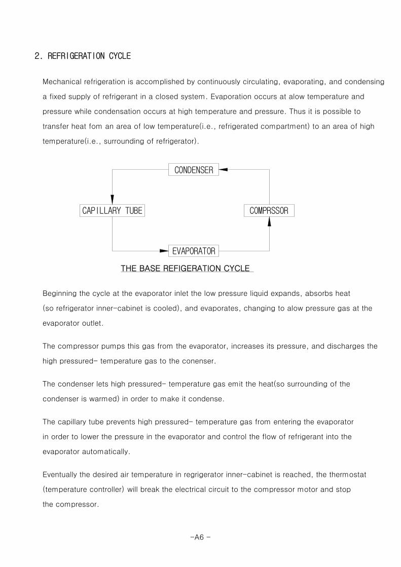
2. REFRIGERATION CYCLE
Mechanical refrigeration is accomplished by continuously circulating, evaporating, and condensing
a fixed supply of refrigerant in a closed system. Evaporation occurs at alow temperature and
pressure while condensation occurs at high temperature and pressure. Thus it is possible to
transfer heat fom an area of low temperature(i.e., refrigerated compartment) to an area of high
temperature(i.e., surrounding of refrigerator).
THE BASE REFIGERATION CYCLE
Beginning the cycle at the evaporator inlet the low pressure liquid expands, absorbs heat
(so refrigerator inner-cabinet is cooled), and evaporates, changing to alow pressure gas at the
evaporator outlet.
The compressor pumps this gas from the evaporator, increases its pressure, and discharges the
high pressured- temperature gas to the conenser.
The condenser lets high pressured- temperature gas emit the heat(so surrounding of the
condenser is warmed) in order to make it condense.
The capillary tube prevents high pressured- temperature gas from entering the evaporator
in order to lower the pressure in the evaporator and control the flow of refrigerant into the
evaporator automatically.
Eventually the desired air temperature in regrigerator inner-cabinet is reached, the thermostat
(temperature controller) will break the electrical circuit to the compressor motor and stop
the compressor.
CONDENSER
COMPRSSORCAPILLARY TUBE
EVAPORATOR
-A6 -

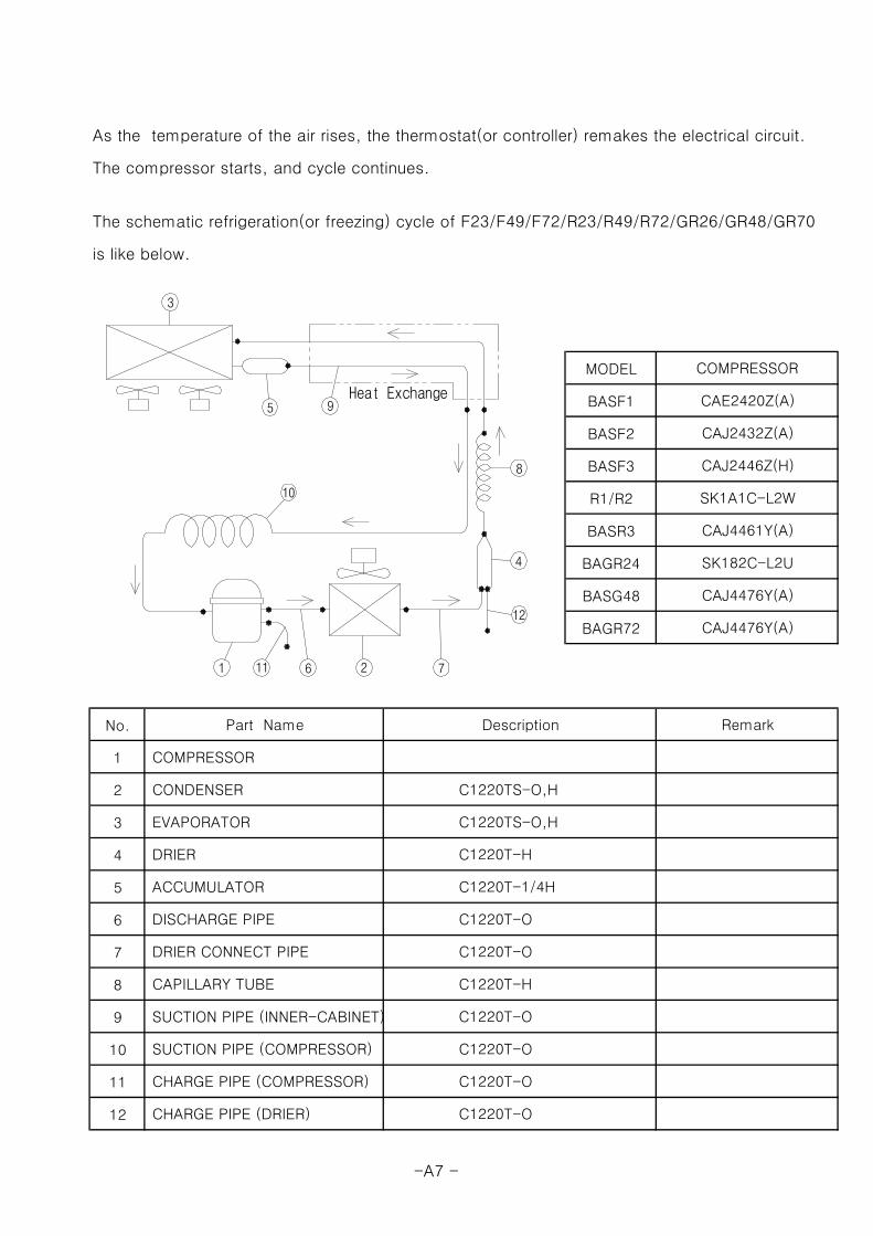
As the temperature of the air rises, the thermostat(or controller) remakes the electrical circuit.
The compressor starts, and cycle continues.
The schematic refrigeration(or freezing) cycle of F23/F49/F72/R23/R49/R72/GR26/GR48/GR70
is like below.
MODEL
BASF1
BASF2
BASF3
R1/R2
BASR3
BAGR24
BASG48
BAGR72
No.
1
2
3
4
5
6
7
8
9
10
11
12
SK1A1C-L2W
CAJ4476Y(A)
CAJ2432Z(A)
CAJ2446Z(H)
Remark
CAJ4461Y(A)
SK182C-L2U
CAJ4476Y(A)
COMPRESSOR
CAE2420Z(A)
CHARGE PIPE (DRIER) C1220T-O
SUCTION PIPE (COMPRESSOR) C1220T-O
CHARGE PIPE (COMPRESSOR) C1220T-O
DRIER C1220T-H
ACCUMULATOR C1220T-1/4H
SUCTION PIPE (INNER-CABINET) C1220T-O
DISCHARGE PIPE C1220T-O
DRIER CONNECT PIPE C1220T-O
CAPILLARY TUBE C1220T-H
EVAPORATOR C1220TS-O,H
Part Name Description
COMPRESSOR
CONDENSER C1220TS-O,H
Heat Exchange
21
3
4
6
5 9
8
7
10
12
11
-A7 -

-A8 -
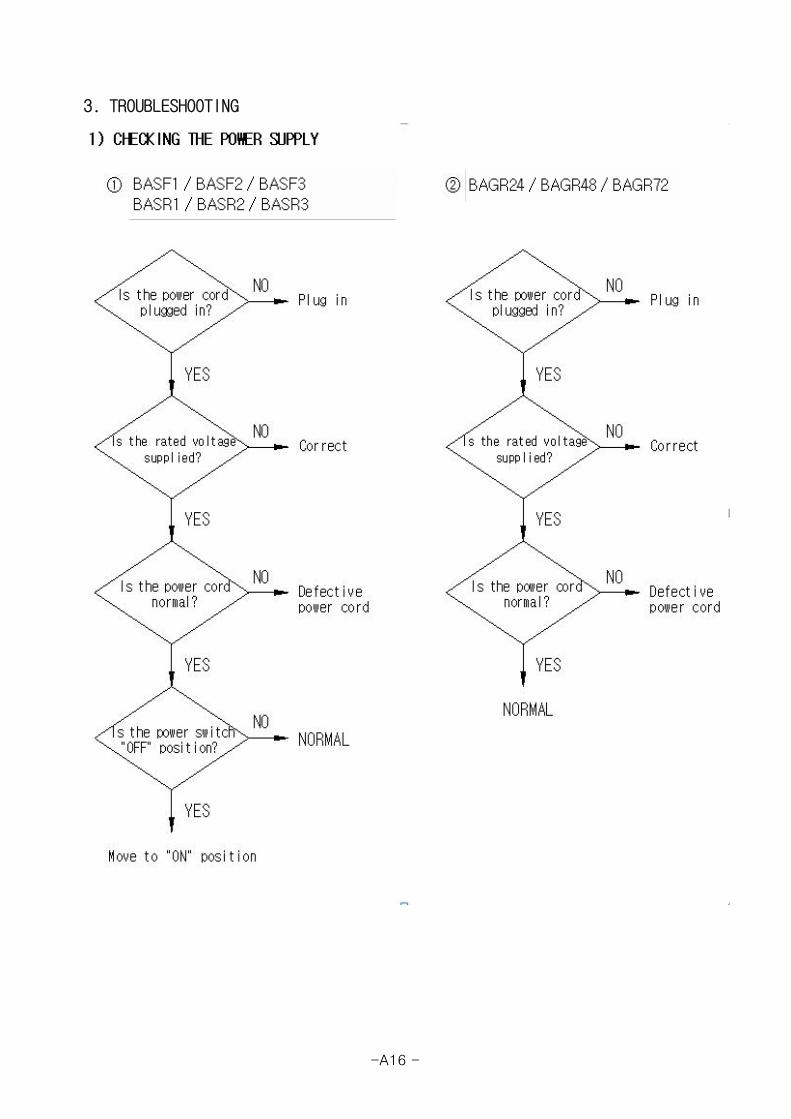
3. TROUBLESHOOTING
-A16 -
-A17 -

-A18 -

-A19 -
-A20 -
-A21 -

-A22 -

-A23 -
-A24 -

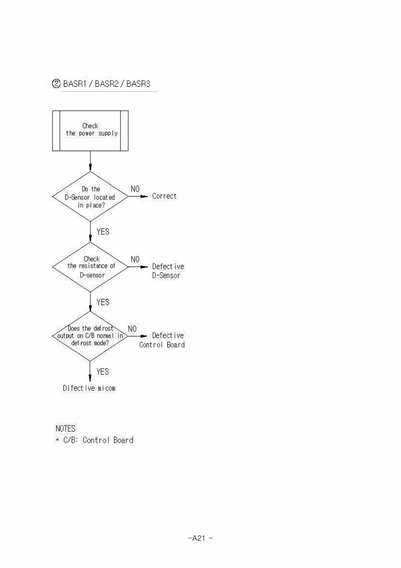
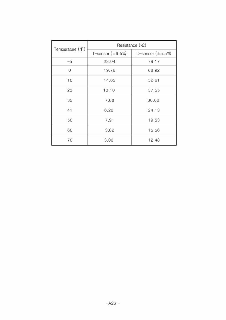
9) CHECKING SENSOR
Sensor assembly consists of T-sensor (lead wire: orange) and
D-sensor (lead wire: blue).
The T-sensor is used for cabinet temperature control and
the D-sensor is used for defrost control.
The resistance of the sensor varies depending on temperature.
If you Immerse the sensor in a glass containing ice water for 2 minutes
and then check for the resistance between sensor leads,
the normal reading is 7.88㏀ (T-sensor) / 30㏀ (D-sensor).
-A25 -

T-sensor (±6.5%) D-sensor (±5.5%)
-5 23.04 79.17
0 19.76 68.92
10 14.65 52.61
23 10.10 37.55
32 7.88 30.00
41 6.20 24.13
50 7.91 19.53
60 3.82 15.56
70 3.00 12.48
Temperature (℉)Resistance (㏀)
-A26 -

-A27 -

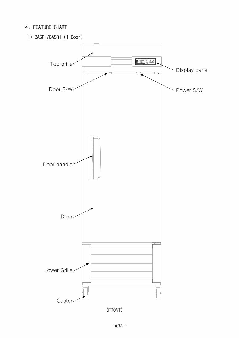
4. FEATURE CHART
1) BASF1/BASR1 (1 Door)
(FRONT)
Top grille
Door S/W
Door handle
Door
Lower Grille
Caster
Power S/W
Display panel
-A38 -
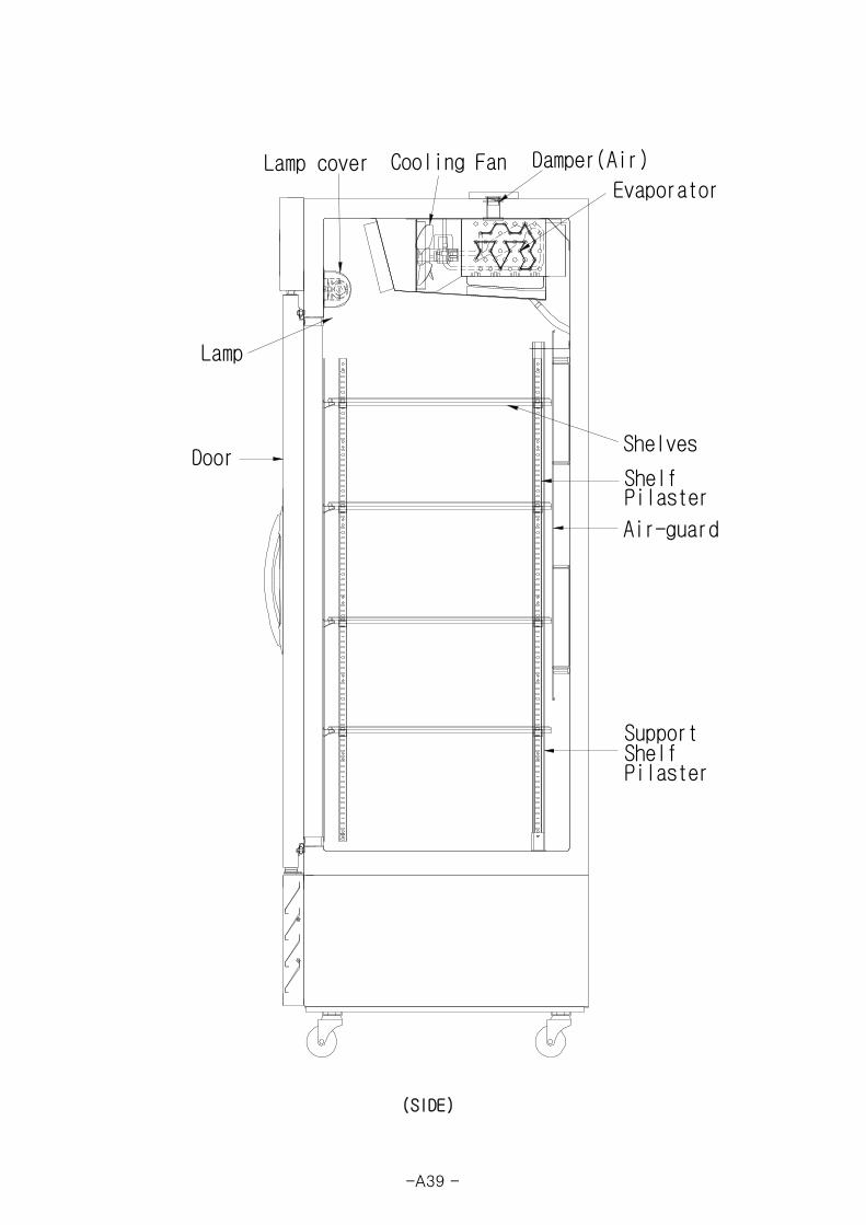
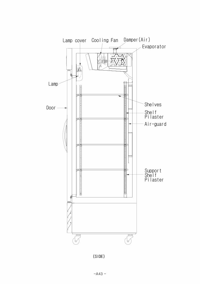
(SIDE)
Evaporator
Lamp
Lamp cover Cooling Fan
PilasterShelfSupport
Damper(Air)
Air-guard
Pilaster
Shelves
ShelfDoor
-A39 -

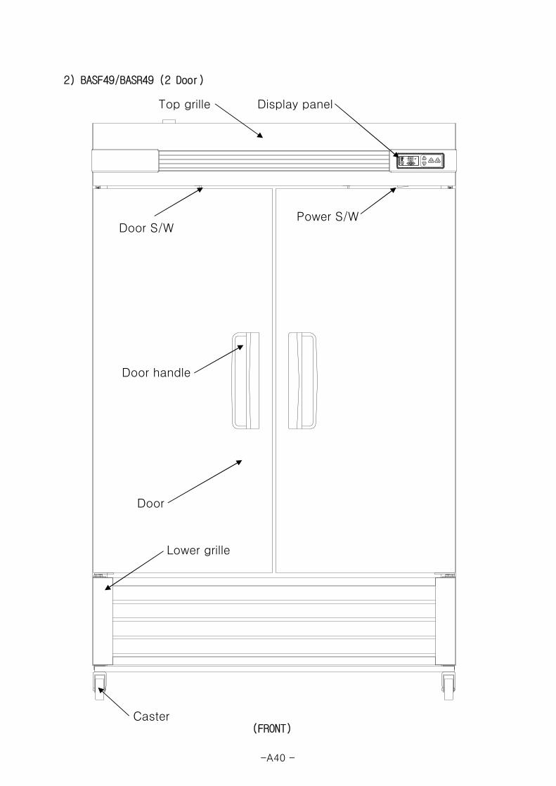
2) BASF49/BASR49 (2 Door)
(FRONT)
Top grille
Door S/W
Door handle
Door
Lower grille
Caster
Display panel
Power S/W
-A40 -

(SIDE)
Door
Air-guard
Pilaster
Shelves
Shelf
Damper(Air)
Evaporator
Lamp
Lamp cover Cooling Fan
PilasterShelfSupport
-A41 -
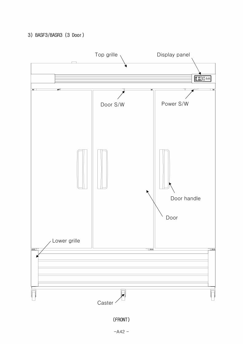
3) BASF3/BASR3 (3 Door)
(FRONT)
Top grille
Power S/W
Display panel
Door S/W
Door handle
Door
Lower grille
Caster
-A42 -

(SIDE)
Door
Air-guard
Pilaster
Shelves
Shelf
Damper(Air)
Evaporator
Lamp
Lamp cover Cooling Fan
PilasterShelfSupport
-A43 -
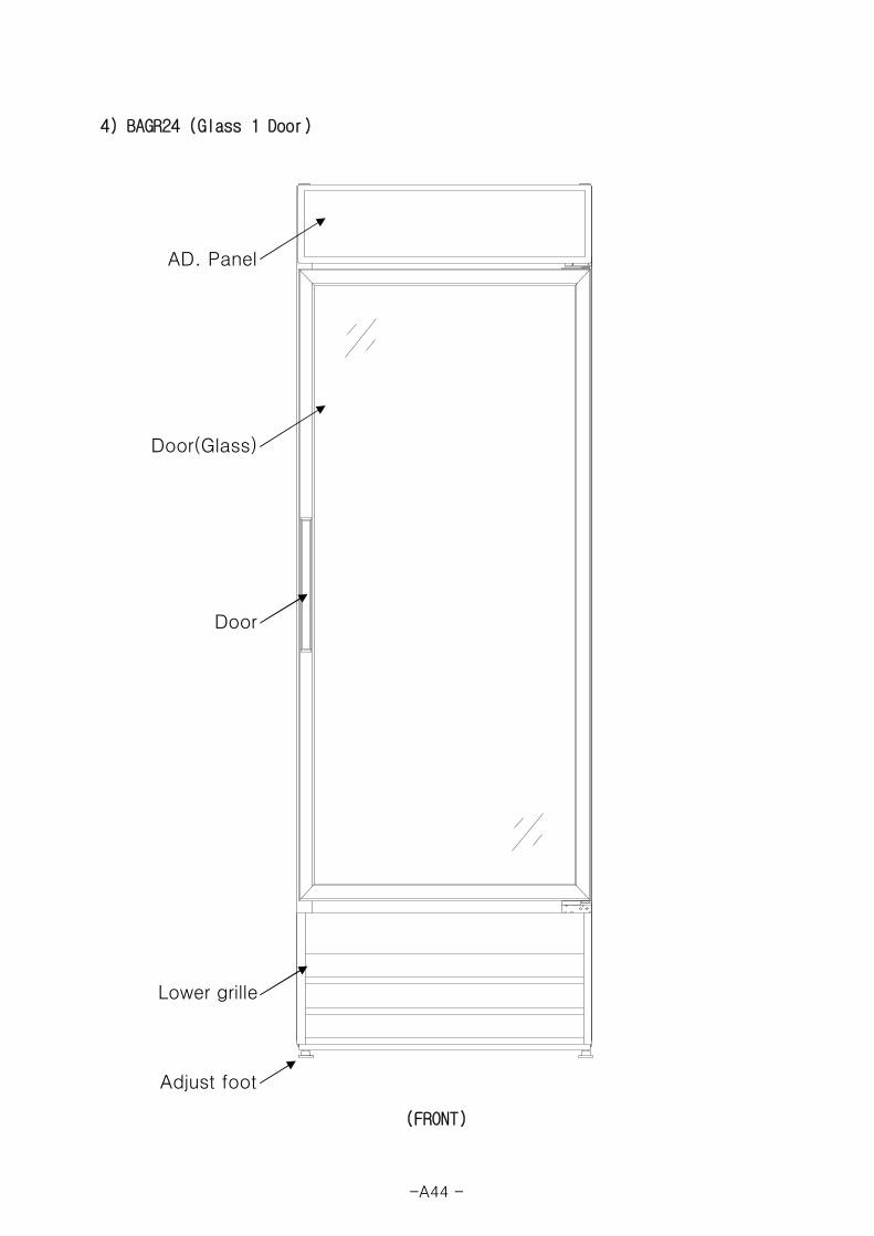
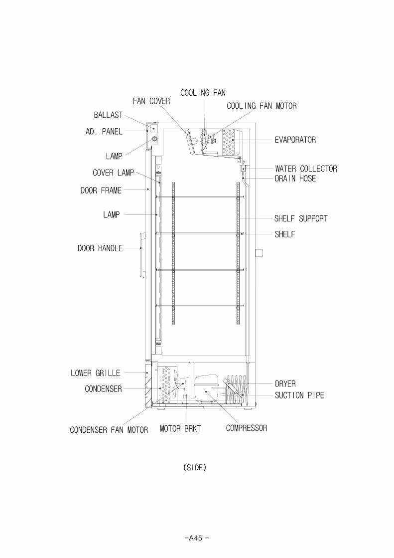
4) BAGR24 (Glass 1 Door)
(FRONT)
AD. Panel
Door(Glass)
Door
Lower grille
Adjust foot
-A44 -

(SIDE)
DOOR HANDLE
CONDENSER
COMPRESSOR
EVAPORATOR
SHELF
SHELF SUPPORT
DRAIN HOSE
FAN COVER
WATER COLLECTOR
LAMP
DOOR FRAME
AD. PANEL
DRYER
CONDENSER FAN MOTOR
COOLING FAN
COOLING FAN MOTOR
SUCTION PIPE
BALLAST
LOWER GRILLE
MOTOR BRKT
LAMP
COVER LAMP
-A45 -
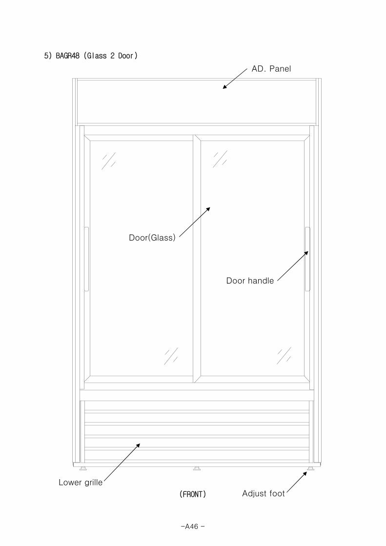
5) BAGR48 (Glass 2 Door)
(FRONT)
AD. Panel
Door(Glass)
Door handle
Lower grille
Adjust foot
-A46 -
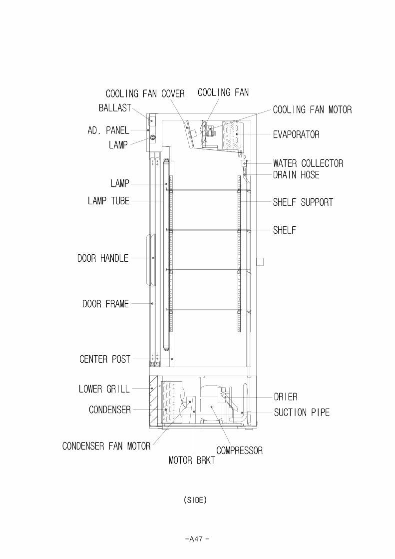
(SIDE)
EVAPORATOR
COOLING FAN
COOLING FAN MOTORBALLAST
AD. PANEL
WATER COLLECTORDRAIN HOSE
SHELF SUPPORT
SHELF
CONDENSER
LOWER GRILL
DOOR HANDLE
DOOR FRAME
COMPRESSOR
SUCTION PIPE
COOLING FAN COVER
LAMP
LAMP TUBE
DRIER
CONDENSER FAN MOTOR
MOTOR BRKT
CENTER POST
LAMP
-A47 -
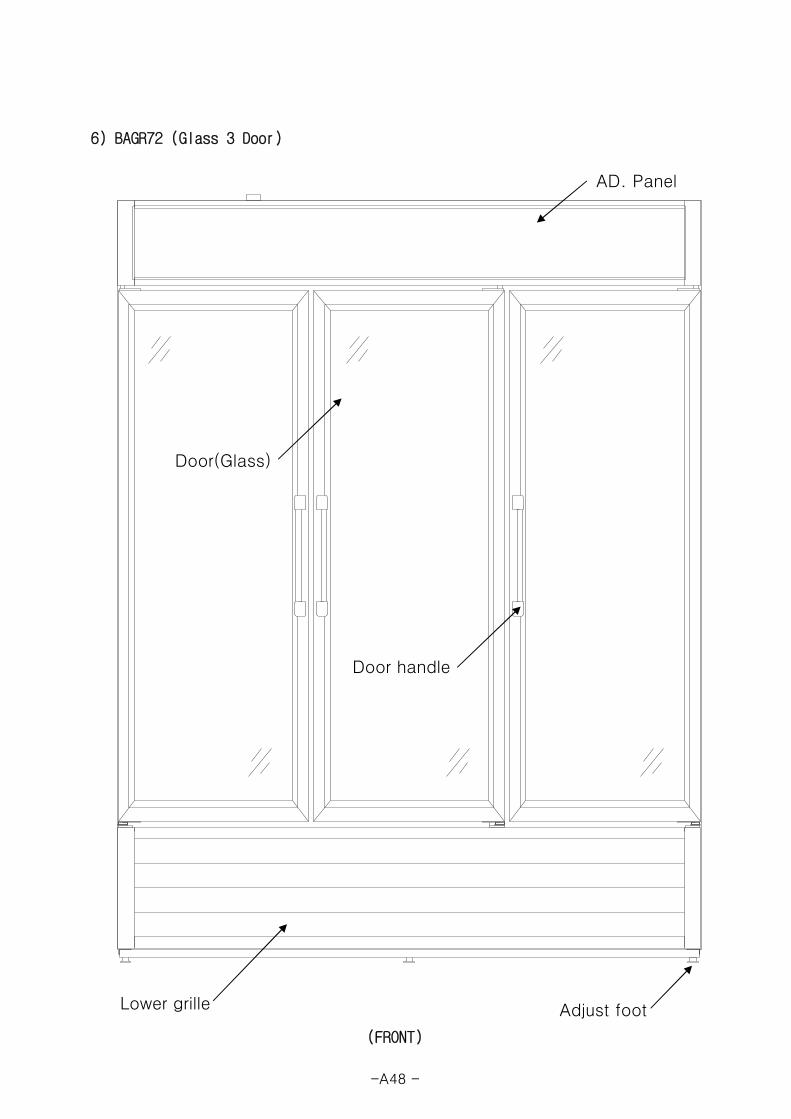
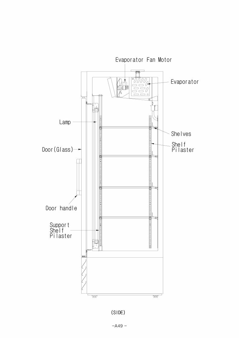
6) BAGR72 (Glass 3 Door)
(FRONT)
Lower grille Adjust foot
AD. Panel
Door(Glass)
Door handle
-A48 -

(SIDE)
Door handle
Door(Glass)
Evaporator
Shelves
Evaporator Fan Motor
Lamp
SupportShelfPilaster
ShelfPilaster
-A49 -

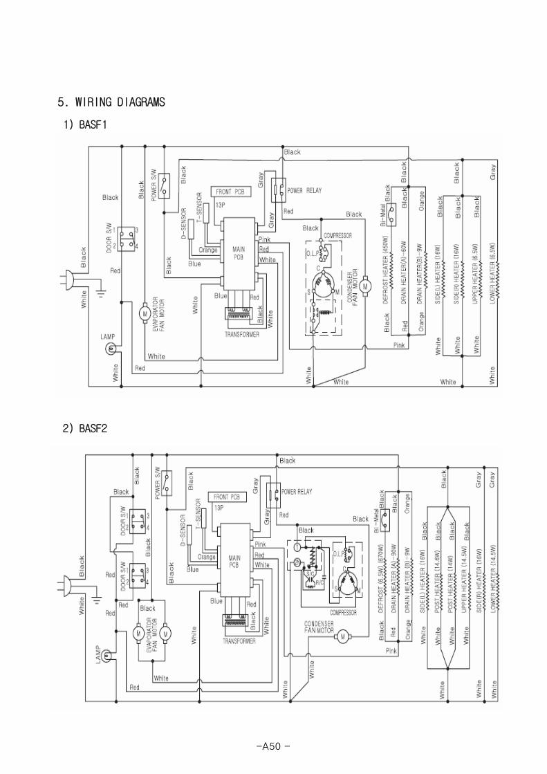
5. WIRING DIAGRAMS
1) BASF1
2) BASF2
-A50 -
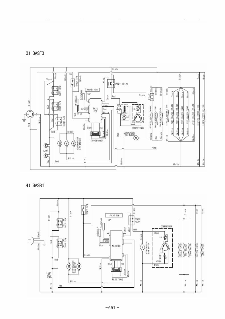
3) BASF3
4) BASR1
-A51 -
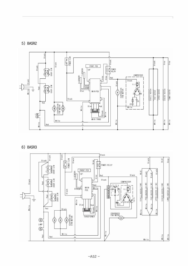
5) BASR2
6) BASR3
-A52 -
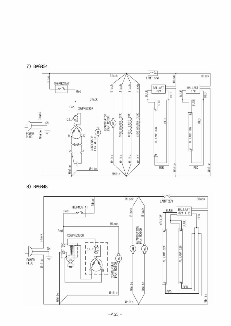
7) BAGR24
8) BAGR48
-A53 -
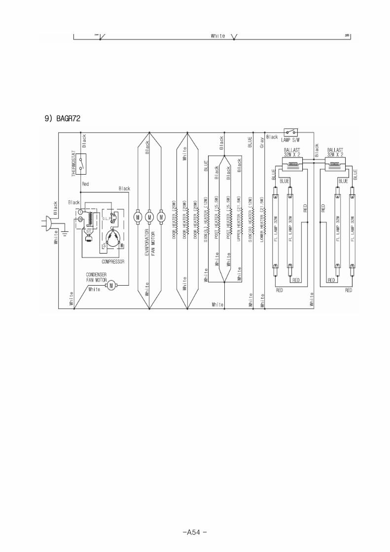
9) BAGR72
-A54 -

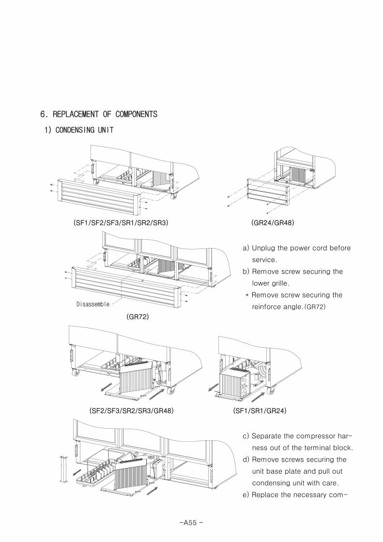
6. REPLACEMENT OF COMPONENTS
1) CONDENSING UNIT
(SF1/SF2/SF3/SR1/SR2/SR3) (GR24/GR48)
a) Unplug the power cord before
service.
b) Remove screw securing the
lower grille.
* Remove screw securing the
reinforce angle.(GR72)
(GR72)
(SF2/SF3/SR2/SR3/GR48) (SF1/SR1/GR24)
c) Separate the compressor har-
ness out of the terminal block.
d) Remove screws securing the
unit base plate and pull out
condensing unit with care.
e) Replace the necessary com-
DisassembleDisassembleDisassemble
-A55 -
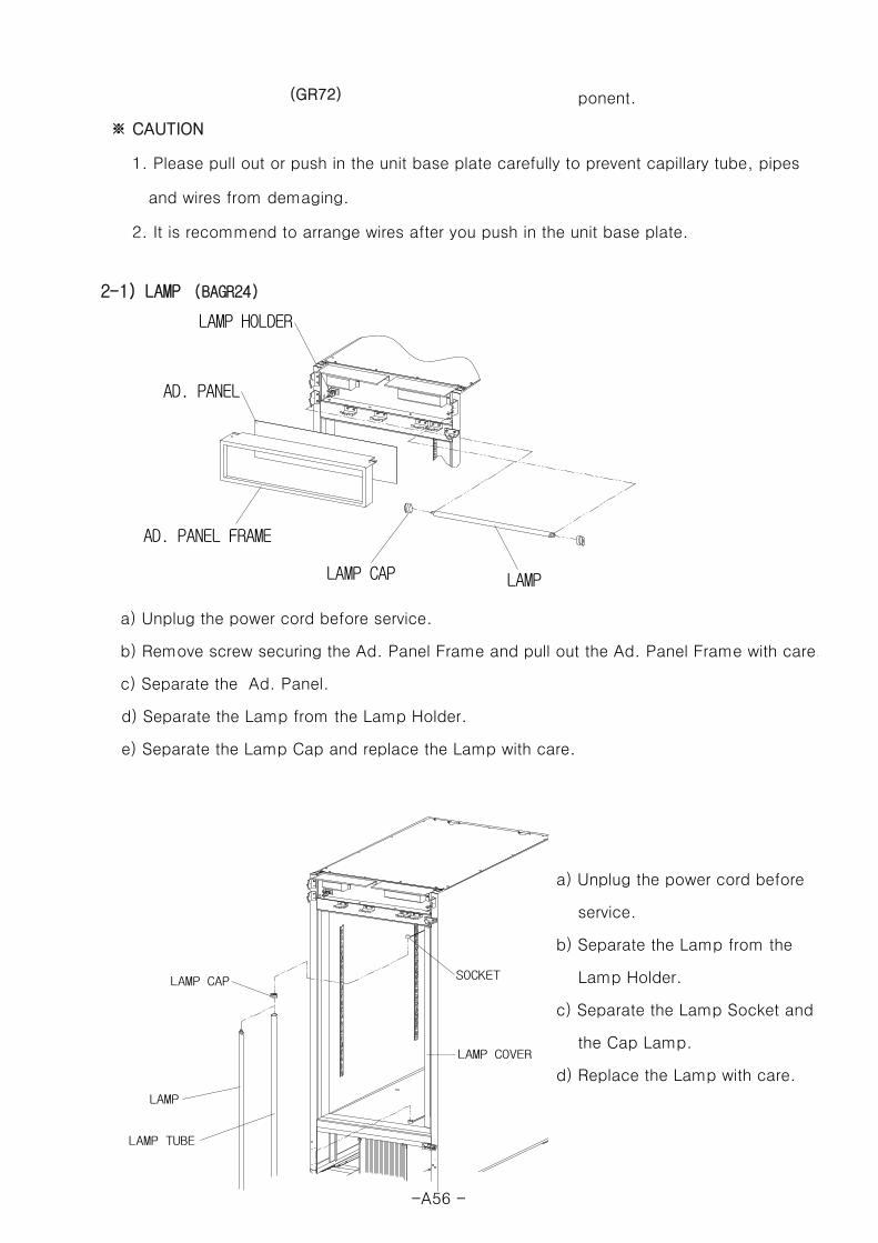
(GR72) ponent.
※ CAUTION
1. Please pull out or push in the unit base plate carefully to prevent capillary tube, pipes
and wires from demaging.
2. It is recommend to arrange wires after you push in the unit base plate.
2-1) LAMP (BAGR24)
a) Unplug the power cord before service.
b) Remove screw securing the Ad. Panel Frame and pull out the Ad. Panel Frame with care.
c) Separate the Ad. Panel.
d) Separate the Lamp from the Lamp Holder.
e) Separate the Lamp Cap and replace the Lamp with care.
a) Unplug the power cord before
service.
b) Separate the Lamp from the
Lamp Holder.
c) Separate the Lamp Socket and
the Cap Lamp.
d) Replace the Lamp with care.
LAMP CAP LAMP
AD. PANEL FRAME
LAMP HOLDER
AD. PANEL
LAMP
LAMP TUBE
LAMP CAP SOCKET
LAMP COVER
-A56 -

♠ Lamp Description : AC115V, F17T8/TL950
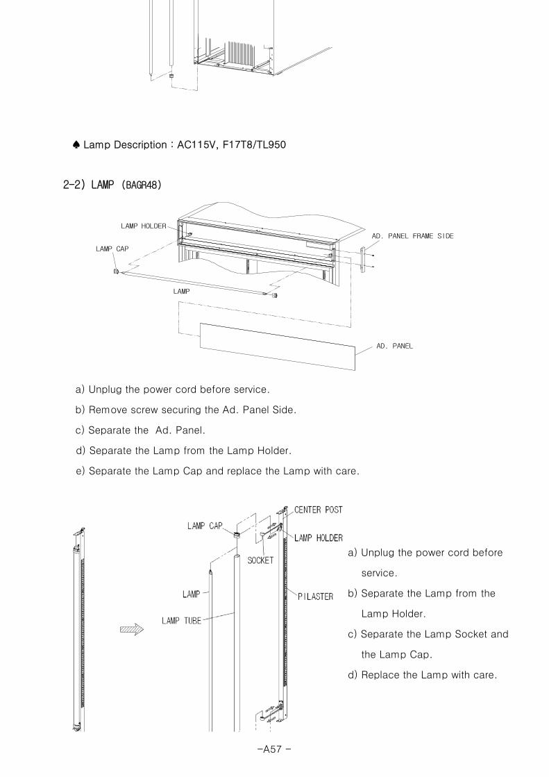
2-2) LAMP (BAGR48)
a) Unplug the power cord before service.
b) Remove screw securing the Ad. Panel Side.
c) Separate the Ad. Panel.
d) Separate the Lamp from the Lamp Holder.
e) Separate the Lamp Cap and replace the Lamp with care.
a) Unplug the power cord before
service.
b) Separate the Lamp from the
Lamp Holder.
c) Separate the Lamp Socket and
the Lamp Cap.
d) Replace the Lamp with care.
1
3
2
71
2
7
6
4
3
2
5
1
AD. PANEL
LAMP CAP
LAMP HOLDER
AD. PANEL FRAME SIDE
LAMP
-A57 -
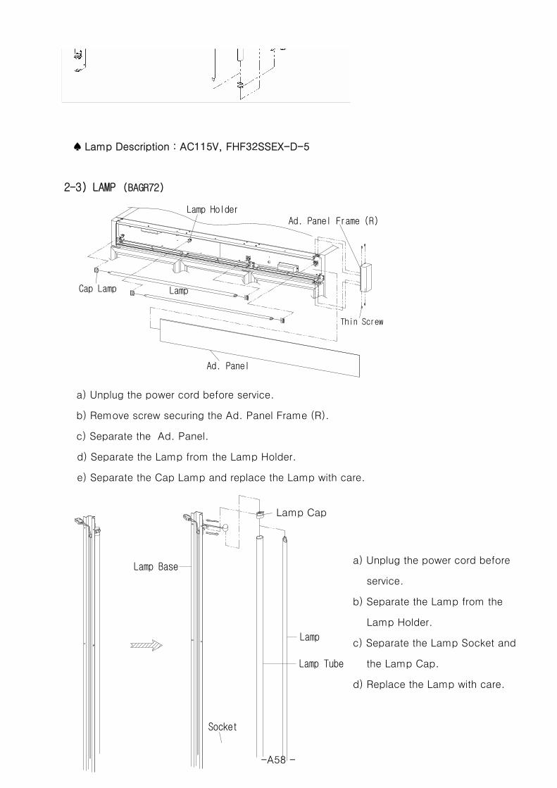
♠ Lamp Description : AC115V, FHF32SSEX-D-5
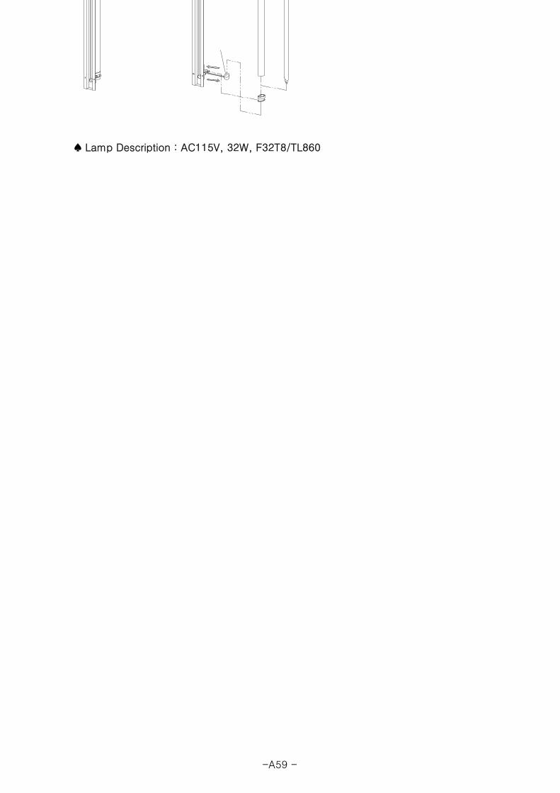
2-3) LAMP (BAGR72)
a) Unplug the power cord before service.
b) Remove screw securing the Ad. Panel Frame (R).
c) Separate the Ad. Panel.
d) Separate the Lamp from the Lamp Holder.
e) Separate the Cap Lamp and replace the Lamp with care.
a) Unplug the power cord before
service.
b) Separate the Lamp from the
Lamp Holder.
c) Separate the Lamp Socket and
the Lamp Cap.
d) Replace the Lamp with care.
Cap Lamp
Lamp
Lamp Tube
Socket
Lamp Base
Lamp Cap
Ad. Panel
Ad. Panel Frame (R)
Cap Lamp Lamp
Lamp Holder
Thin Screw
-A58 -

♠ Lamp Description : AC115V, 32W, F32T8/TL860
-A59 -
■ MODEL : BASF1/BASF2/BASF3 (FREEZER) BASR1/BASR2/BASR3 (REFRIGERATOR)
BAGR24/BAGR48/BAGR72(MERCHANDISERS)
B. OPERATION AND ELECTRONIC CONTROLLER FUNCTION
1. OPERATION FOR BASF1, BASF2, BASF3, BASR1, BASR2, BASR3 MODELS - B2
1) BASIC OPERATION
2) ELECTRONIC CONTROLLER SETING MODE
3) NORMAL CONTROL PROCESS
4) ERROR CODE
2. OPERATION FOR BAGR24, BAGR48, BAGR3 MODELS - - - - - - - - - B9
1) BASIC OPERATION
2) ELECTRONIC CONTROLLER SETING MODE
3) NORMAL CONTROL PROCESS
4) ERROR CODE
3. INSTRUCTION FOR RE-HINGING DOOR - - - - - - - - - - - - - B10
- B1 -
1. OPERATION FOR BASF1/BASF2/BASF3, BASR1/BASR2/BASR3
1) BASIC OPERATION
① Plug in the power cord and turn on the power switch located on the bottom of the top grille
right side.
[ The unit should be plugged into a 115V±10%, 60Hz (BASF1, BASF2, BASR1, BASR2, BASR3 models)
[ The unit should be plugged into a 115V/208~230V, 60Hz (BASF3 model) ]
② Display panel will be lightened for 2 seconds with buzzer then displays cabinet interior
temperature (T-sensor) and running conditions.
* Freezer : If cabinet interior temperature is higher than 14℉ compressor will run without
delay, and lower than 14℉, compressor will run after 3 minutes.
* Refrigerator : If cabinet interior temperature is higher than 50℉ compressor will run
without delay, and lower than 50℉, compressor will run after 3 minutes.
③ The default OPERATING TEMPERATURE SETTING
* Freezer : Temperature set point (setting mode sign [st]) is –5℉
Temperature differential set point (setting mode sign [di]) is 8℉.
(Operating Temperature : -14℉ ~ -4℉)
Range of adjustable set point: -22℉ ~ 8℉
* Refrigerator : Temperature set point (setting mode sign [st]) is 36℉
Temperature differential set point (setting mode sign [di]) is 8℉.
(Operating Temperature : 34℉ ~ 44℉)
Range of adjustable set point: 25℉ ~ 50℉
④ Defrost frequency
* Freezer : It is controlled by MICOM and the default defrost frequency is 6 hours.
* Refrigerator : It is controlled by MICOM and the default defrost frequency is 12 hours.
⑤ The light inside the cabinet comes on when the door is opened.
The cabinet interior cooling fan has 3 seconds delay when the door is closed.
When COMP is OFF, Eva FAN repeats ON and OFF every 2 min.
When door is opened during Eva FAN OFF, Evan FAN resets to 2min ON.
(Running after 3 seconds is not applied)
When door is opened during Eva FAN ON, Eva FAN resets to 2min ON
(Running after 3 seconds is not applied)
⑥ If door is opened, door open warnign sign (LED) will turn on.
- B2 -
If door is opened more than 30 seconds, the sound alarm beeps 3times,
if open more than 60 seconds, the sound alarm beeps 5 times and if open more than 5 minutes,
the sound alarm will beep continuously.
⑦ Cabinet interior temperature
* Freezer : If it is higher than 14℉(BASF1, BASF2, BASF3), the panel displays [Hi] and
lower than -50℉(BASF1, BASF2, BASF3), the panel displays [Lo].
* Refrigerator : If it is higher than 68℉(BASF1, BASF2, BASF3), the panel displays [Hi] and
lower than 14℉(BASF1, BASF2, BASF3), the panel displays [Lo].
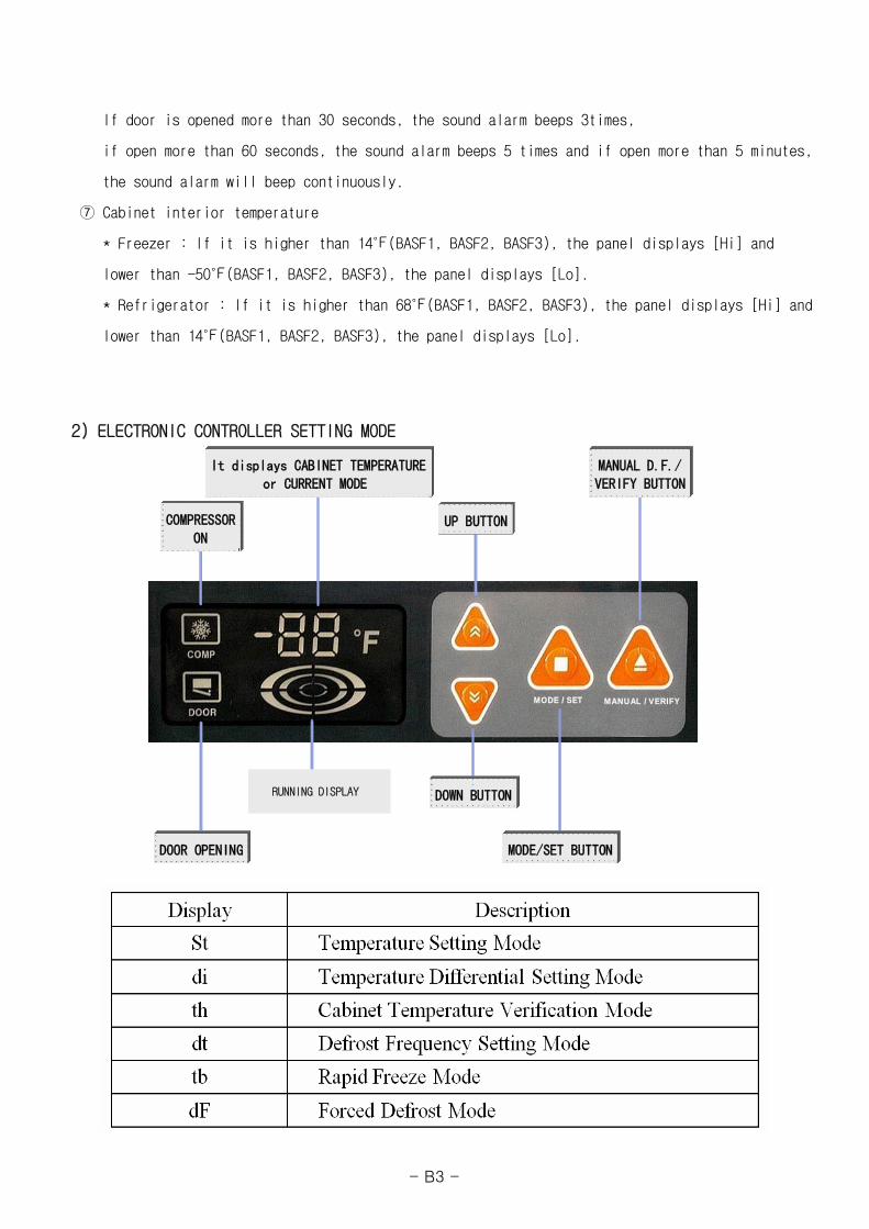
2) ELECTRONIC CONTROLLER SETTING MODE
D.F.MODE / SET MANUAL / VERIFY
POWER SWITCH ON
COMPRESSORON
It displays CABINET TEMPERATUREor CURRENT MODE
DOOR OPENING
UP BUTTON
MANUAL D.F./VERIFY BUTTON
MODE/SET BUTTON
DOWN BUTTON
D.F.MODE / SET MANUAL / VERIFYMODE / SET MANUAL / VERIFY
POWER SWITCH ONPOWER SWITCH ON
COMPRESSORON
COMPRESSORON
It displays CABINET TEMPERATUREor CURRENT MODE
It displays CABINET TEMPERATUREor CURRENT MODE
DOOR OPENINGDOOR OPENING
UP BUTTONUP BUTTON
MANUAL D.F./VERIFY BUTTONMANUAL D.F./VERIFY BUTTON
MODE/SET BUTTONMODE/SET BUTTON
DOWN BUTTONDOWN BUTTONRUNNING DISPLAY
- B3 -
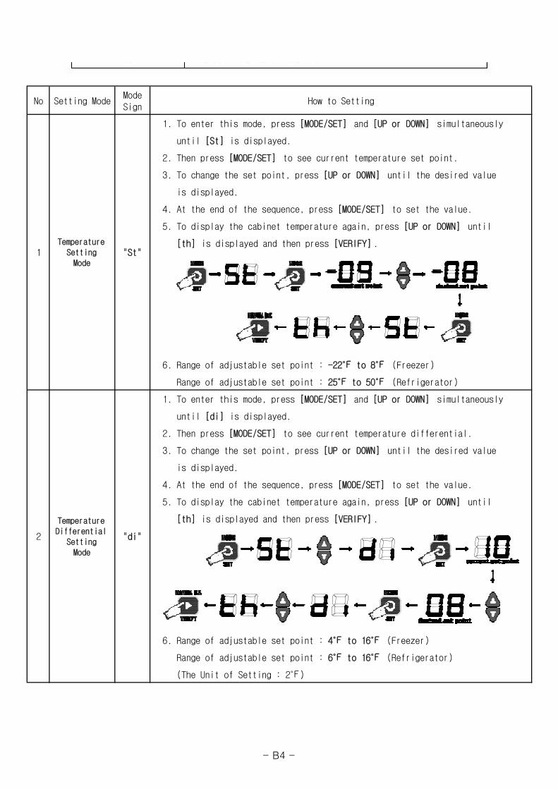
No Setting ModeModeSign
How to Setting
1. To enter this mode, press [MODE/SET] and [UP or DOWN] simultaneously
until [St] is displayed.
2. Then press [MODE/SET] to see current temperature set point.
3. To change the set point, press [UP or DOWN] until the desired value
is displayed.
4. At the end of the sequence, press [MODE/SET] to set the value.
5. To display the cabinet temperature again, press [UP or DOWN] until
[th] is displayed and then press [VERIFY] .
6. Range of adjustable set point : -22℉ to 8℉ (Freezer)
Range of adjustable set point : 25℉ to 50℉ (Refrigerator)
1. To enter this mode, press [MODE/SET] and [UP or DOWN] simultaneously
until [di] is displayed.
2. Then press [MODE/SET] to see current temperature differential.
3. To change the set point, press [UP or DOWN] until the desired value
is displayed.
4. At the end of the sequence, press [MODE/SET] to set the value.
5. To display the cabinet temperature again, press [UP or DOWN] until
[th] is displayed and then press [VERIFY] .
6. Range of adjustable set point : 4℉ to 16℉ (Freezer)
Range of adjustable set point : 6℉ to 16℉ (Refrigerator)
(The Unit of Setting : 2℉)
TemperatureDifferential
SettingMode
1
2
"St"Temperature
SettingMode
"di"
- B4 -
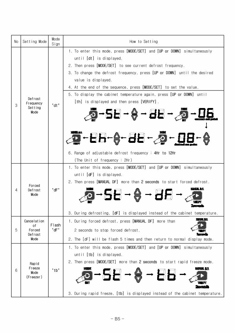
No Setting ModeModeSign
How to Setting
1. To enter this mode, press [MODE/SET] and [UP or DOWN] simultaneously
until [dt] is displayed.
2. Then press [MODE/SET] to see current defrost frequency.
3. To change the defrost frequency, press [UP or DOWN] until the desired
value is displayed.
4. At the end of the sequence, press [MODE/SET] to set the value.
5. To display the cabinet temperature again, press [UP or DOWN] until
[th] is displayed and then press [VERIFY] .
6. Range of adjustable defrost frequency : 4Hr to 12Hr
(The Unit of frequency : 2Hr)
1. To enter this mode, press [MODE/SET] and [UP or DOWN] simultaneously
until [dF] is displayed.
2. Then press [MANUAL DF] more than 2 seconds to start forced defrost.
3. During defrosting, [dF] is displayed instead of the cabinet temperature.
1. During forced defrost, press [MANUAL DF] more than
2 seconds to stop forced defrost.
2. The [dF] will be flash 5 times and then return to normal display mode.
1. To enter this mode, press [MODE/SET] and [UP or DOWN] simultaneously
until [tb] is displayed.
2. Then press [MODE/SET] more than 2 seconds to start rapid freeze mode.
3. During rapid freeze, [tb] is displayed instead of the cabinet temperature.
DefrostFrequencySettingMode
3
6
5
Cancelationof
ForcedDefrostMode
"dt"
Flash"dF"
RapidFreezeMode
(Freezer)
"tb"
4ForcedDefrostMode
"dF"
- B5 -
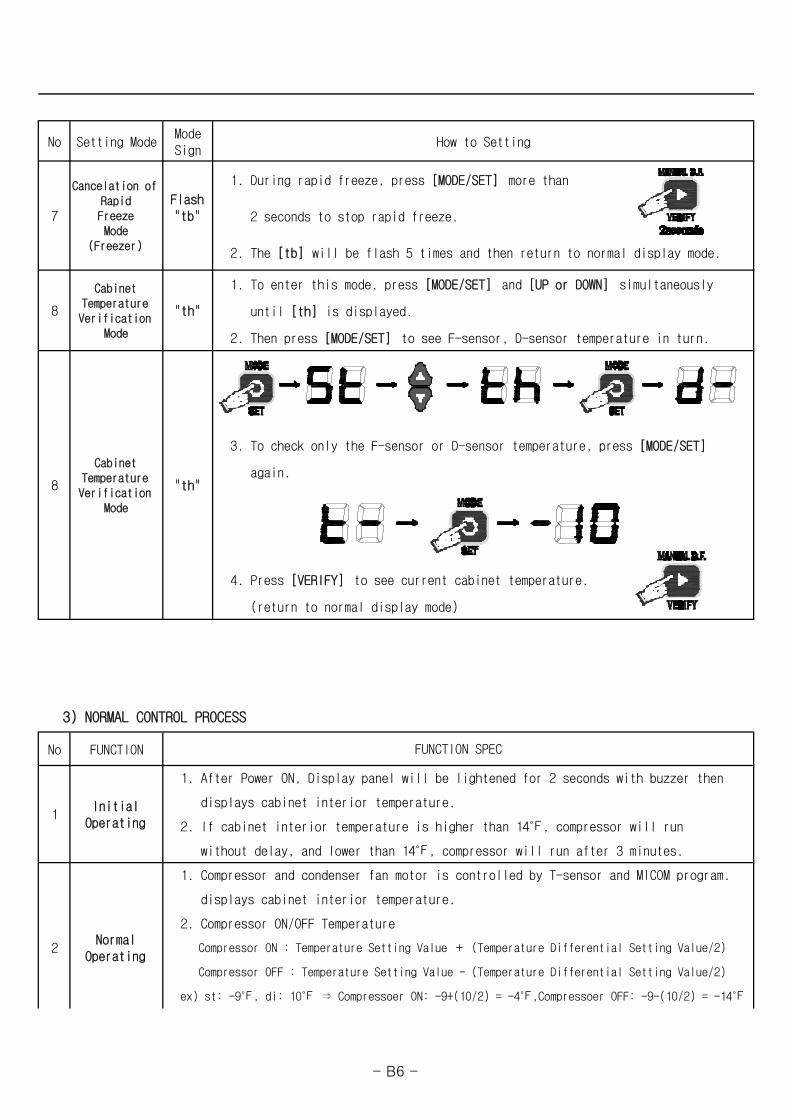
No Setting ModeModeSign
How to Setting
1. During rapid freeze, press [MODE/SET] more than
2 seconds to stop rapid freeze.
2. The [tb] will be flash 5 times and then return to normal display mode.
1. To enter this mode, press [MODE/SET] and [UP or DOWN] simultaneously
until [th] is displayed.
2. Then press [MODE/SET] to see F-sensor, D-sensor temperature in turn.
3. To check only the F-sensor or D-sensor temperature, press [MODE/SET]
again.
4. Press [VERIFY] to see current cabinet temperature.
(return to normal display mode)
3) NORMAL CONTROL PROCESS
No FUNCTION
2
1Initial
Operating 2. If cabinet interior temperature is higher than 14℉, compressor will run
without delay, and lower than 14℉, compressor will run after 3 minutes.
displays cabinet interior temperature.
2. Compressor ON/OFF Temperature
ex) st: -9℉, di: 10℉ ⇒ Compressoer ON: -9+(10/2) = -4℉,Compressoer OFF: -9-(10/2) = -14℉
NormalOperating
8
CabinetTemperatureVerification
Mode
"th"
FUNCTION SPEC
1. After Power ON, Display panel will be lightened for 2 seconds with buzzer then
displays cabinet interior temperature.
Compressor ON : Temperature Setting Value + (Temperature Differential Setting Value/2)
Compressor OFF : Temperature Setting Value - (Temperature Differential Setting Value/2)
1. Compressor and condenser fan motor is controlled by T-sensor and MICOM program.
7
Cancelation ofRapidFreezeMode
(Freezer)
Flash"tb"
8
CabinetTemperatureVerification
Mode
"th"
- B6 -
No FUNCTION
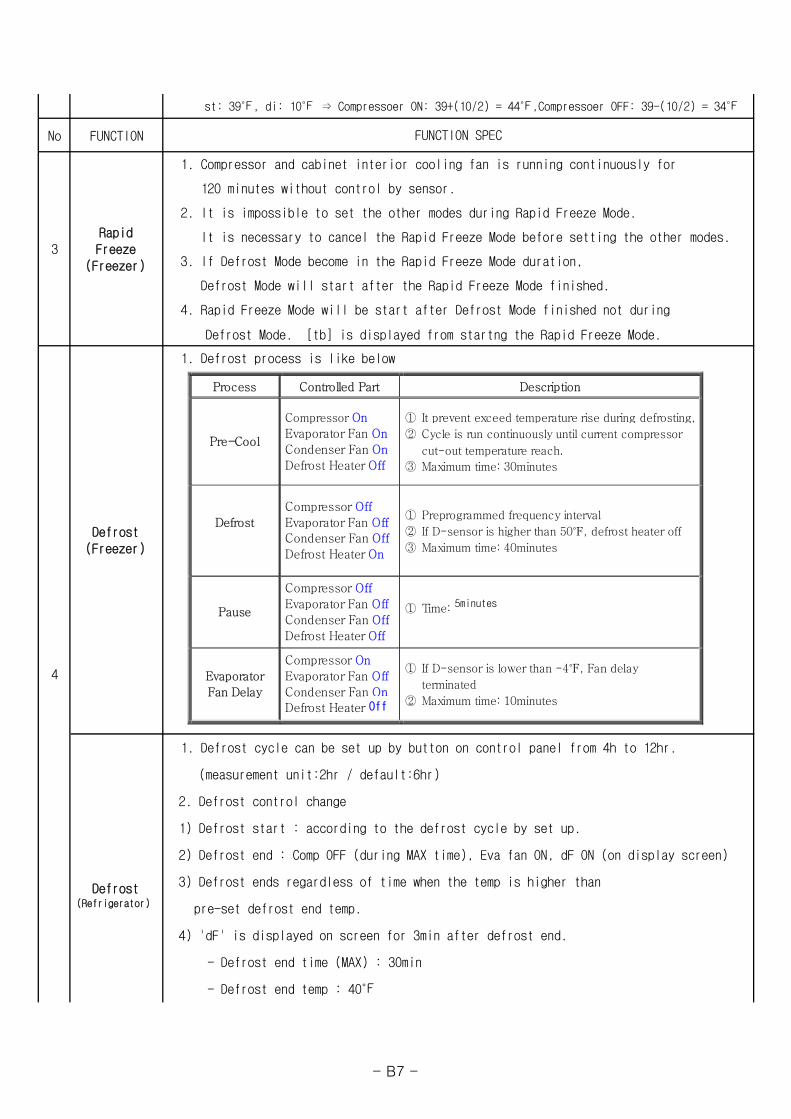
Defrost Mode. [tb] is displayed from startng the Rapid Freeze Mode.
Defrost(Refrigerator)
1. Compressor and cabinet interior cooling fan is running continuously for
(measurement unit:2hr / default:6hr)
2. Defrost control change
1) Defrost start : according to the defrost cycle by set up.
1. Defrost process is like below
st: 39℉, di: 10℉ ⇒ Compressoer ON: 39+(10/2) = 44℉,Compressoer OFF: 39-(10/2) = 34℉
4
FUNCTION SPEC
Defrost(Freezer)
3. If Defrost Mode become in the Rapid Freeze Mode duration,
120 minutes without control by sensor.
2. It is impossible to set the other modes during Rapid Freeze Mode.
It is necessary to cancel the Rapid Freeze Mode before setting the other modes.
1. Defrost cycle can be set up by button on control panel from 4h to 12hr.
pre-set defrost end temp.
- Defrost end time (MAX) : 30min
- Defrost end temp : 40℉
3RapidFreeze
(Freezer)
Defrost Mode will start after the Rapid Freeze Mode finished.
4. Rapid Freeze Mode will be start after Defrost Mode finished not during
3) Defrost ends regardless of time when the temp is higher than
2) Defrost end : Comp OFF (during MAX time), Eva fan ON, dF ON (on display screen)
4) 'dF' is displayed on screen for 3min after defrost end.
Process Controlled Part Description
Pre-Cool
Compressor On
Evaporator Fan On
Condenser Fan On
Defrost Heater Off
① It prevent exceed temperature rise during defrosting,
② Cycle is run continuously until current compressor
cut-out temperature reach.
③ Maximum time: 30minutes
Defrost
Compressor Off
Evaporator Fan Off Condenser Fan Off
Defrost Heater On
① Preprogrammed frequency interval
② If D-sensor is higher than 50℉, defrost heater off
③ Maximum time: 40minutes
Pause
Compressor Off
Evaporator Fan Off
Condenser Fan Off
Defrost Heater Off
① Time: 3minutes
Evaporator
Fan Delay
Compressor On
Evaporator Fan Off
Condenser Fan On Defrost Heater On
① If D-sensor is lower than -4℉, Fan delay
terminated
② Maximum time: 10minutes Off
5minutes
- B7 -
No FUNCTION
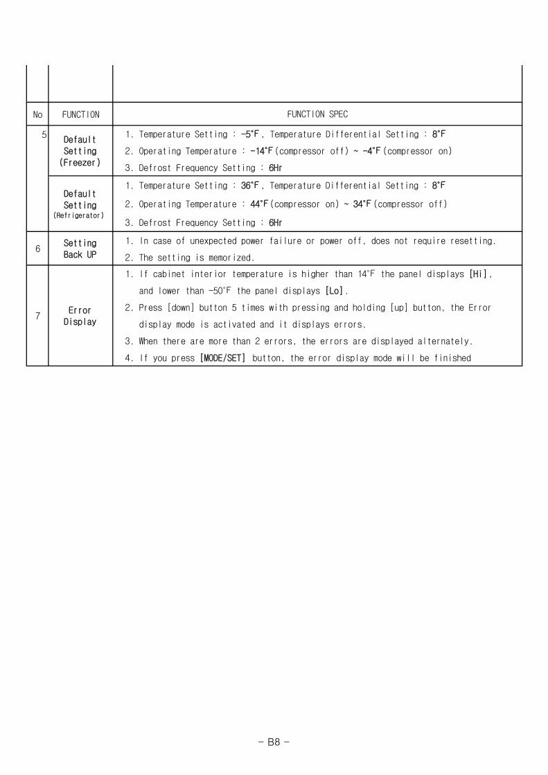
5
1. In case of unexpected power failure or power off, does not require resetting.
2. The setting is memorized.
2. Operating Temperature : -14℉(compressor off) ~ -4℉(compressor on)
1. Temperature Setting : 36℉, Temperature Differential Setting : 8℉
3. Defrost Frequency Setting : 6Hr
display mode is activated and it displays errors.
3. When there are more than 2 errors, the errors are displayed alternately.
6
4. If you press [MODE/SET] button, the error display mode will be finished
7Error
Display
1. If cabinet interior temperature is higher than 14℉ the panel displays [Hi],
and lower than -50℉ the panel displays [Lo].
2. Press [down] button 5 times with pressing and holding [up] button, the Error
SettingBack UP
DefaultSetting
(Refrigerator)
DefaultSetting
(Freezer)
FUNCTION SPEC
2. Operating Temperature : 44℉(compressor on) ~ 34℉(compressor off)
3. Defrost Frequency Setting : 6Hr
1. Temperature Setting : -5℉, Temperature Differential Setting : 8℉
- B8 -
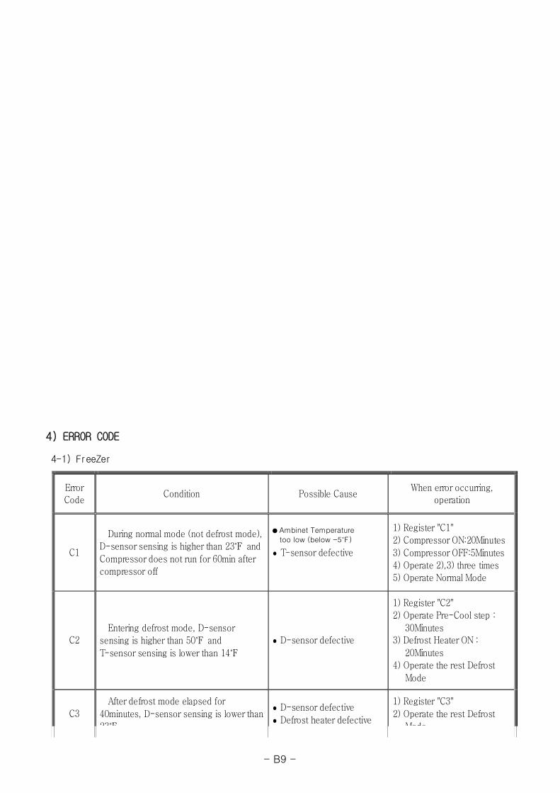
4) ERROR CODE
4-1) FreeZer
Error Code
Condition Possible Cause When error occurring,
operation
C1
During normal mode (not defrost mode),
D-sensor sensing is higher than 23℉ and
Compressor does not run for 60min after
compressor off
T-sensor defective
1) Register "C1"
2) Compressor ON:20Minutes
3) Compressor OFF:5Minutes
4) Operate 2),3) three times
5) Operate Normal Mode
C2 Entering defrost mode, D-sensor
sensing is higher than 50℉ and
T-sensor sensing is lower than 14℉
D-sensor defective
1) Register "C2"
2) Operate Pre-Cool step :
30Minutes 3) Defrost Heater ON :
20Minutes
4) Operate the rest Defrost
Mode
C3
After defrost mode elapsed for
40minutes, D-sensor sensing is lower than
23℉
D-sensor defective
Defrost heater defective
1) Register "C3"
2) Operate the rest Defrost
Mode
● Ambinet Temperature
too low (below -5℉)
- B9 -
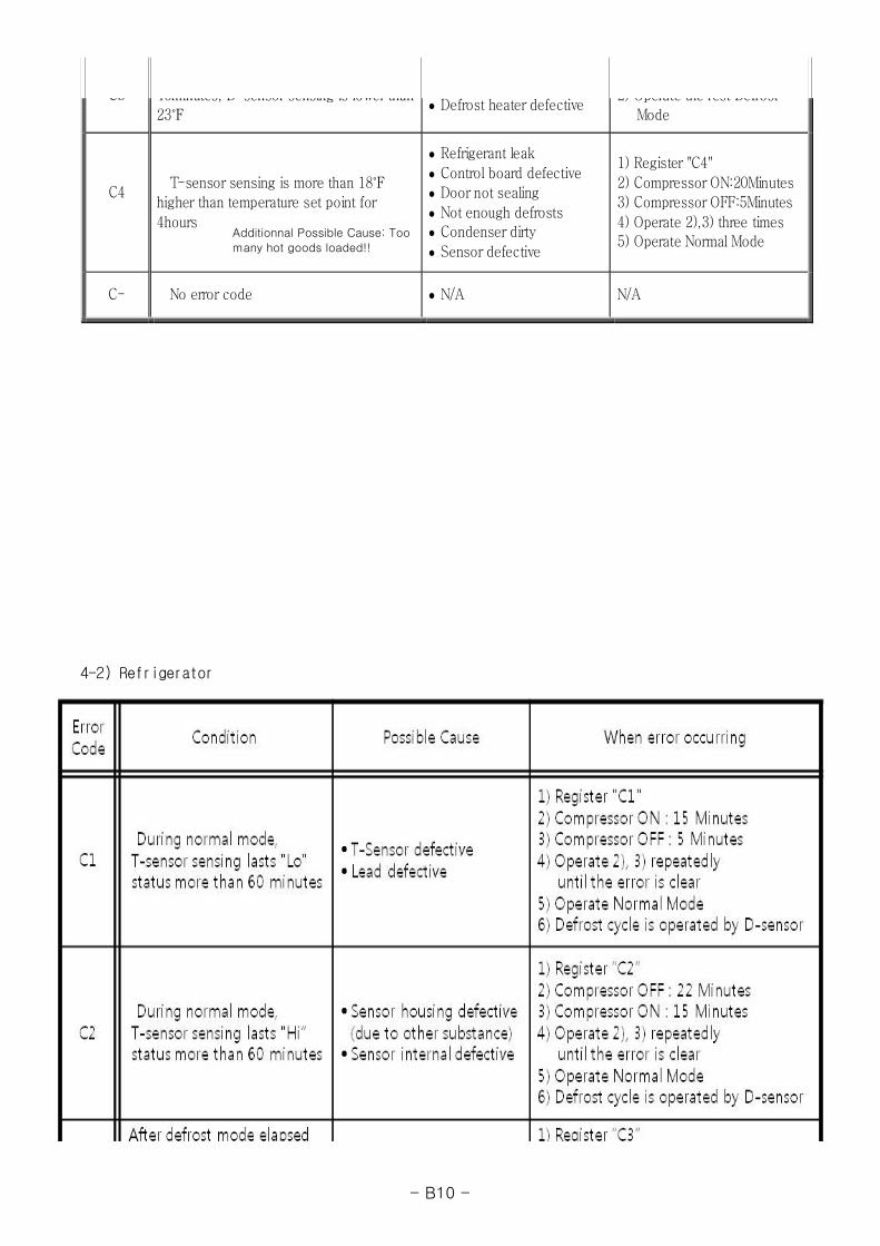
4-2) Refrigerator
C3 40minutes, D sensor sensing is lower than
23℉ Defrost heater defective
2) Operate the rest Defrost
Mode
C4
T-sensor sensing is more than 18℉
higher than temperature set point for
4hours
Refrigerant leak
Control board defective
Door not sealing
Not enough defrosts Condenser dirty
Sensor defective
1) Register "C4"
2) Compressor ON:20Minutes
3) Compressor OFF:5Minutes
4) Operate 2),3) three times 5) Operate Normal Mode
C- No error code N/A N/A
Additionnal Possible Cause: Too
many hot goods loaded!!
- B10 -
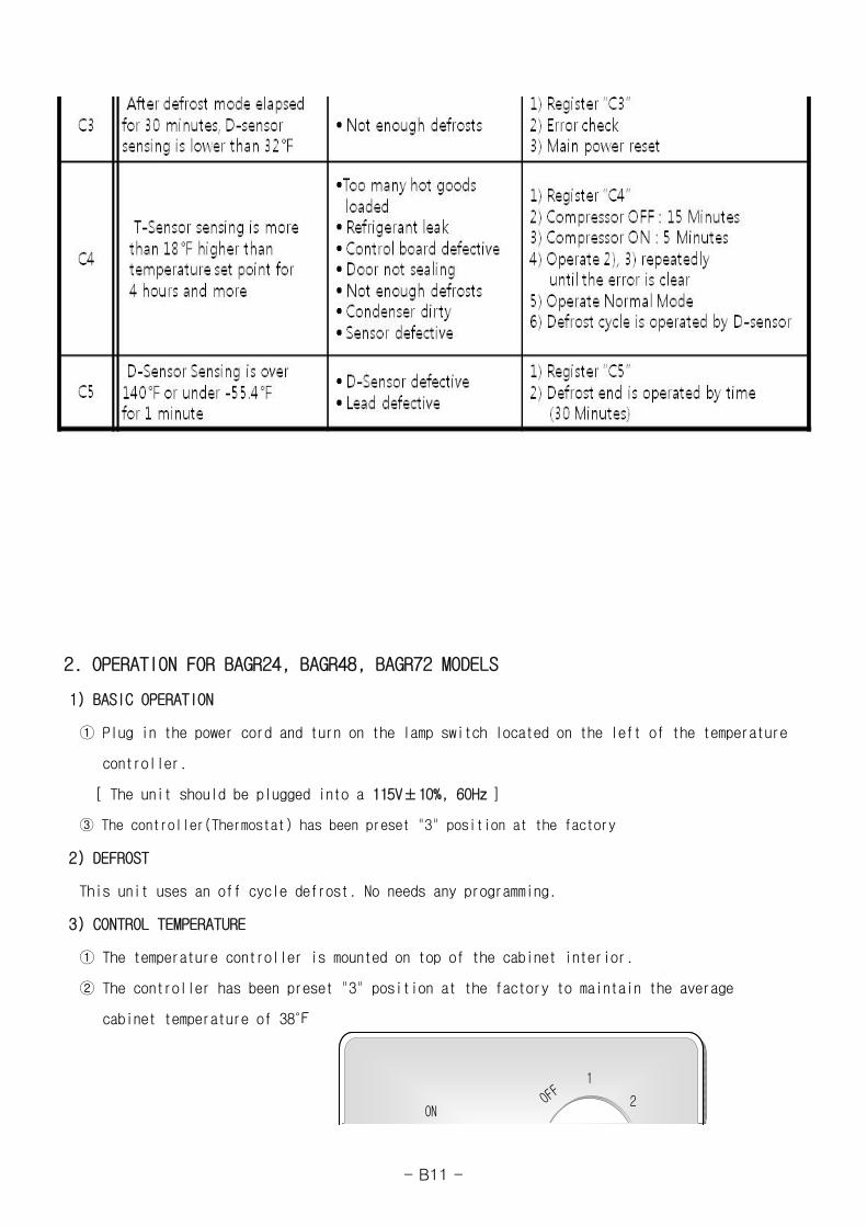
2. OPERATION FOR BAGR24, BAGR48, BAGR72 MODELS
1) BASIC OPERATION
① Plug in the power cord and turn on the lamp switch located on the left of the temperature
controller.
[ The unit should be plugged into a 115V±10%, 60Hz ]
③ The controller(Thermostat) has been preset "3" position at the factory
2) DEFROST
This unit uses an off cycle defrost. No needs any programming.
3) CONTROL TEMPERATURE
① The temperature controller is mounted on top of the cabinet interior.
② The controller has been preset "3" position at the factory to maintain the average
cabinet temperature of 38℉
OFF
1
2ON
OFF
1
2ON
- B11 -
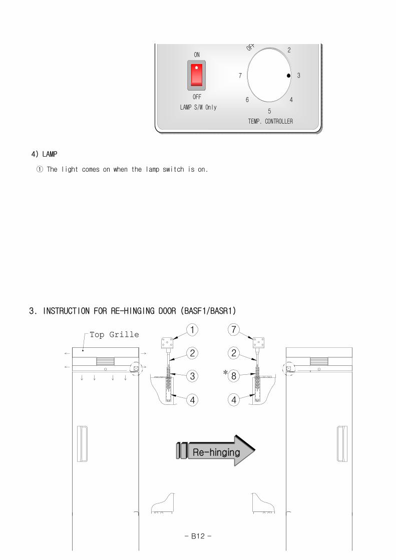
4) LAMP
① The light comes on when the lamp switch is on.
3. INSTRUCTION FOR RE-HINGING DOOR (BASF1/BASR1)
1
2
3
4 4
*
7
2
8
ReRe--hinginghinging
Top GrilleTop Grille 1
2
3
4 4
*
7
2
8
ReRe--hinginghinging
Top GrilleTop Grille
TEMP. CONTROLLER
OFF
2
3
46
5
7
ON
OFF
LAMP S/W Only
TEMP. CONTROLLER
OFF
2
3
46
5
7
ON
OFF
LAMP S/W Only
- B12 -
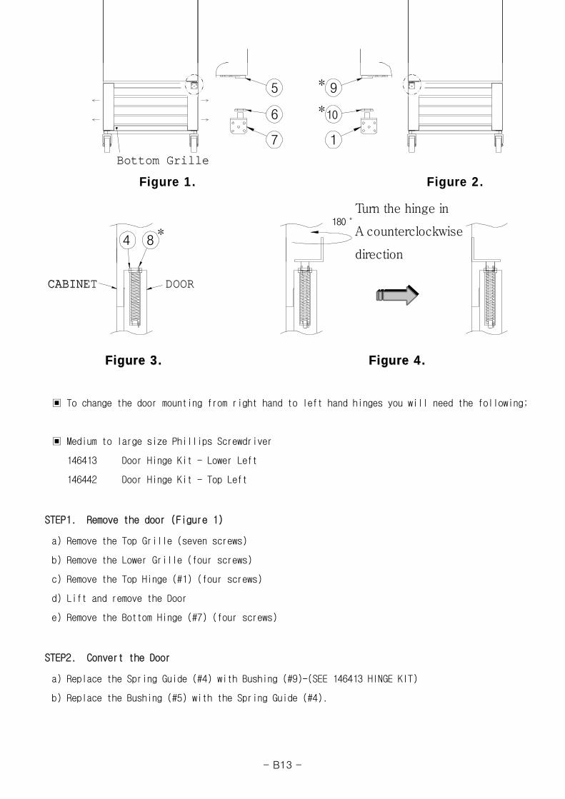
▣ To change the door mounting from right hand to left hand hinges you will need the following;
▣ Medium to large size Phillips Screwdriver
146413 Door Hinge Kit - Lower Left
146442 Door Hinge Kit - Top Left
STEP1. Remove the door (Figure 1)
a) Remove the Top Grille (seven screws)
b) Remove the Lower Grille (four screws)
c) Remove the Top Hinge (#1) (four screws)
d) Lift and remove the Door
e) Remove the Bottom Hinge (#7) (four screws)
STEP2. Convert the Door
a) Replace the Spring Guide (#4) with Bushing (#9)-(SEE 146413 HINGE KIT)
b) Replace the Bushing (#5) with the Spring Guide (#4).
5
7
6
*84
1
180˚
*
*
9
10
Bottom GrilleBottom Grille
Figure 2.Figure 2.Figure 1.Figure 1.
Figure 3.Figure 3. Figure 4.Figure 4.
Turn the hinge inTurn the hinge in
A counterclockwiseA counterclockwise
directiondirection
CABINETCABINET DOORDOOR
5
7
6
*84
1
180˚
*
*
9
10
Bottom GrilleBottom Grille
Figure 2.Figure 2.Figure 1.Figure 1.
Figure 3.Figure 3. Figure 4.Figure 4.
Turn the hinge inTurn the hinge in
A counterclockwiseA counterclockwise
directiondirection
CABINETCABINET DOORDOOR
- B13 -
STEP3. Reinstall the Door (figure 2)
a) Install Bottom Left Hinge (#1) with Bushing (#10)-(SEE 146413 HINGE KIT)
b) Set Door in place on Bottom Hinge
c) Insert Spring (#8) (silver) into Spring Guide (#4) as shown in figure 3-(SEE 146442 HINGE KIT)
d) Install the Top Hinge (#7) as shown in figure 4-(SEE 146442 HINGE KIT)
(confirm that spring ends are engaged in the spring guide and hinge)
e) Replace the Top and Lower Grilles
Note:
The silver colored spring (#8) is for left hand hinged door and the yellow color spring (#3)
is for right hand hinged doors.
The letter "L" is marked on the left hand bushings (#9 and 10)
- B14 -
■ MODEL : BASF1/BASF2/BASF3(FREEZER) BASR1/BASR2/BASR3(REFRIGERATOR)
BAGR24/BAGR48/BAGR72 (MERCHANDISERS)
A. COMMERCIAL FREEZER, REFRIGERATOR GENERAL
1. SPECIFICATION - - - - - - - - - - - - - - - - - - - - - - A2
1) GENERAL
2) MAIN COMPONENTS
2. REFRIGERATION CYCLE - - - - - - - - - - - - - - - - - - - A6
3. TROUBLE SHOOTING - - - - - - - - - - - - - - - - - - - - - A8
1) CHECKING THE POWER SUPPLY
2) CHECKING THE POWER SUPPLY OF CONTROL BOARD
3) CHECKING THE CONTROL PART OF REFRIGERATION CYCLE
4) CHECKING THE DEFROST PART
5) WHEN THE UNIT DOES NOT COOL
6) WHEN THERE IS A ABNORMAL NOISE
7) WHE THE TEMPERATURE DOES NOT DISPLAY
8) WHEN THE LAMP DOES NOT LIGHT
9) CHECKING SENSOR
4. FEATURE CHART - - - - - - - - - - - - - - - - - - - - - - - A18
5. WIRING DIAGRAM - - - - - - - - - - - - - - - - - - - - - - A30
6. REPLACEMENT OF COMPONENTS - - - - - - - - - - - - - - - - - A35
-A1 -
1. SPECIFICATION
1) GENERAL - COMMERCIAL FREEZERS AND REFRIGERATORS
BASF1 BASF2 BASF3 BASR1 BASR2 BASR3
23 49 72 23 49 72
20.8 45.2 66.3 20.8 45.2 66.3
(W) 27.4 55.1 78 27.4 55.1 78
(D)
(H)
(W) 23.6 51.4 74.2 23.6 51.4 74.2
(D)
(H)
295 499 622 288 475 609
Swing 1EA Swing 2EA Swing 3EA Swing 1EA Swing 2EA Swing 3EA
4EA 8EA 12EA 4EA 8EA 12EA
AC 115V/208-230V
60Hz
NEMA 14-20P
8.5A 9.5A 9.0A 7.5A 7.5A 10.0A
1/2HP 3/4HP 1.1HP 1/3HP 1/3HP 1/2HP
R-404A(12.0 oz)
R-404A(22.2 oz)
R-404A(23.6 oz)
R-134A(7.4 oz)
R-134A(9.5 oz)
R-134A(14.1 oz)
◈ Above specifications are subjected to change without prior notice for quality improvement.
◈ The nameplate(includes Serial Number) is located on the upper left of the cabint interior.
Door stop equipment
Air suction equipment
Compressor
Plug in - Installation
Range of Temperature
Door auto-close equipment
Refrigerant
120˚ Stop
Amps
Power Voltage
PRODUCT
MODEL
SOLID DOOR FREEZER
Door Material
31.3
83.9
Exterior Dimension(Including casters)
(in)
SOLID DOOR REFRIGERATOR
Capacity (Cu,Ft)
Net Capacity (Cu,Ft)
Net Weight (lbs)
Interior Dimension(Including casters)
(in)
Door Type
Shelves
Air damper
4in × 4EACaster
Condensing unit
32 ~ 40 ℉
Auto-close for Spring
25
60.8
Stainless steel (STS)
AC 115V/60Hz
NEMA 5-15P
Below 0 ℉
AC 115V/60Hz
NEMA 5-15P
Sliding Type
-A2 -
2) MAIN COMPONENTS - COMMERCIAL FREEZERS AND REFRIGERATORS
BASF1 BASF2 BASF3 BASR1 BASR2 BASR3
CAE2420Z(A)(Tecumseh-France)
CAJ2432Z(A)(Tecumseh-France)
CAJ2446Z(H)(Tecumseh-France)
CAJ4476Y(A)(Tecumseh-France)
LBP 571 LBP 808 LBP 1219 LBP 1586
CSIR CSR CSR CSIR
MST16AHN GA3PJU00 MST00AHN GA3SJU81
3ARR12KPF*483 3ARR3*5R* 3ARR3*3A* 3ARR18A100B
315㎌/160V 315㎌/160V 88㎌/160V 250㎌/160V
- 30㎌/400V 15㎌/160V -
25W × 2EA 25W × 2EA
450W 670W 944W - - -
60W 90W 128W - - -
- - -
Running Capacitor
Interior Temp. Indication
12㎌/250V
3/8"
MODEL
Compressor(Manufacture)
Compressor Capacity(kcal/h)
Starting Capacitor
OD 1", XH-9, 1.06oz
Condenser Fan Motor
Defrost sheath heater
Interior Lamp
Temperature Control Thermistor
Digital DisplayRunning Indication
Evaporator pipe Dimensions
Cooling Fan Motor
Evaporator pipe Dimensions
Type of Condenser
Drier
MA7425W1, 120V/60Hz
Defrost for evaporator
IS3225LTSA, 120V/60Hz
Defrost pan heater
Drain heater
Door switch
Power switch
Cu pipe + Al fin
3/8"
LBP 303
PRODUCT
Type of Compressor motor
Compressor O.L.P
Compressor Relay
Type of Evaporator
SOLID DOOR FREEZER SOLID DOOR REFRIGERATOR
Cu pipe + Al fin + Blue color coating
4TM795TFBZZ-53
J531Q34E220M350-3
125㎌/125V
CSR
SK1A1C-L2W(Samsung-Korea)
Digital Display
25W × 1EA 25W × 1EA
Heated defrost(Control of thermistor)
Off cycle
9W
SP201R-7DR, AC125V
SL112A, AC125V/12A
-A3 -
3) GENERAL - MERCHANDISERS
(W)
(D)
(H)
(W)
(D)
(H)
◈ Above specifications are subjected to change without prior notice for quality improvement.
◈ The nameplate(includes Serial Number) is located on the upper left of the cabint interior.
Shelves
Door Type
Door Material
Net Weight (lbs)
Exterior Dimension(Including casters)
(in)
Capacity (Cu,Ft)
R-134A(10.6 oz)
Adjust foot 4EA
Door auto-close equipment
Door stop equipment
Air damper
Adjust foot 6EA
Air suction equipment
Adjust foot 6EACaster
Net Capacity (Cu,Ft)
Interior Dimension(Including casters)
(in)
Power(or Lamp) switch
Refrigerant
Range of Temperature
Power Voltage
Plug in - Installation
Condensing unit
-
Compressor
61.4
2527
Amps
1/2 HP
10.0A
AC 115V/60Hz
NEMA 5-15P
3.9A
66.3
50
78.7
53.2
25
29.9
Door switch
MODEL
PRODUCT
70
BAGR72
MERCHANDISERS
BAGR24 BAGR48
26 48
78.7
28.4
31.3
23.9 47.3
78
31.3
83.9
74.2
11.9A
12EA
25.5
1/4 HP 1/2 HP
60.8
4EA 8EA
62.5
287 474 716
Glass + Al
Swing 3EASwing 1EA Sliding 2EA
32 ~ 40℉
Auto-close for Spring
120˚ Stop - 120˚ Stop
Sliding Type
-
R-134A(16.2 oz)
R-134A(17.6 oz)
-
SL112A, AC125V/12A
-A4 -
4) MAIN COMPONENTS - MERCHANDISERS
17W/32W(Fluorescent lamp)
MA7425W1, 120V/60Hz
1/2"
CAJ4476Y(A)(Tecumseh-France)
3/8"
CRA38014
Cu pipe + Al fin
ThermostatGNF-250L
B232I120RH-A(ADVANCE)
32W × 1EA
Thermostat(GNF-246L)
B232I120RH-A(ADVANCE)
32W(Double)×1EA /17W×1EA
-
Compressor Relay
Compressor(Manufacture)
Condenser Fan Motor
Drier
Starting Capacitor
Type of Evaporator
Interior Lamp
Ad. Panel Fluorescent Lamp
Defrost for evaporator
OD 1", XH-9, 1.06oz
Thermostat(GNF-240L)
Running Indication
32W(Double)×2EA
Off cycle
32W × 2EA(Fluorescent lamp)
32W × 1EA
Cooling Fan Motor
Type of Condenser
Evaporator pipe Dimensions
Interior Temp. Indication
Defrost pan heater
Drain heater
Temperature Control
Ballast
Ballast Name(Manufacture)
PRODUCT
MODEL
Defrost sheath heater
Evaporator pipe Dimensions
Running Capacitor
Compressor Capacity(kcal/h)
Type of Compressor motor
Compressor O.L.P
LBP 1946
RSCR CSIR
MERCHANDISERS
BAGR72BAGR48BAGR24
CSIR
12㎌/250V
3ARR3*2M*
CAJ4476Y(A)(Tecumseh-France)
HBP 1946
SK182C-L2U(SAMSUNG)
LBP 256
CRA38014
GE3ARR3
250㎌/160V
4TM444NHBYY
J531Q32E4R7M1802
- 250㎌/160V
-
DY232 IS120(DOYOUNG)
32W × 1EA(Fluorescent lamp)
32W × 1EA
32W(Double)×1EA
-
IS3225LTSA, 120V/60Hz
Cu pipe + Al fin
-
-
-
-
-
-
-
-
-
-
-A5 -
2. REFRIGERATION CYCLE
Mechanical refrigeration is accomplished by continuously circulating, evaporating, and condensing
a fixed supply of refrigerant in a closed system. Evaporation occurs at alow temperature and
pressure while condensation occurs at high temperature and pressure. Thus it is possible to
transfer heat fom an area of low temperature(i.e., refrigerated compartment) to an area of high
temperature(i.e., surrounding of refrigerator).
THE BASE REFIGERATION CYCLE
Beginning the cycle at the evaporator inlet the low pressure liquid expands, absorbs heat
(so refrigerator inner-cabinet is cooled), and evaporates, changing to alow pressure gas at the
evaporator outlet.
The compressor pumps this gas from the evaporator, increases its pressure, and discharges the
high pressured- temperature gas to the conenser.
The condenser lets high pressured- temperature gas emit the heat(so surrounding of the
condenser is warmed) in order to make it condense.
The capillary tube prevents high pressured- temperature gas from entering the evaporator
in order to lower the pressure in the evaporator and control the flow of refrigerant into the
evaporator automatically.
Eventually the desired air temperature in regrigerator inner-cabinet is reached, the thermostat
(temperature controller) will break the electrical circuit to the compressor motor and stop
the compressor.
CONDENSER
COMPRSSORCAPILLARY TUBE
EVAPORATOR
-A6 -
As the temperature of the air rises, the thermostat(or controller) remakes the electrical circuit.
The compressor starts, and cycle continues.
The schematic refrigeration(or freezing) cycle of F23/F49/F72/R23/R49/R72/GR26/GR48/GR70
is like below.
MODEL
BASF1
BASF2
BASF3
R1/R2
BASR3
BAGR24
BASG48
BAGR72
No.
1
2
3
4
5
6
7
8
9
10
11
12
EVAPORATOR C1220TS-O,H
Part Name Description
COMPRESSOR
CONDENSER C1220TS-O,H
SUCTION PIPE (INNER-CABINET) C1220T-O
DISCHARGE PIPE C1220T-O
DRIER CONNECT PIPE C1220T-O
CAPILLARY TUBE C1220T-H
DRIER C1220T-H
ACCUMULATOR C1220T-1/4H
CHARGE PIPE (DRIER) C1220T-O
SUCTION PIPE (COMPRESSOR) C1220T-O
CHARGE PIPE (COMPRESSOR) C1220T-O
COMPRESSOR
CAE2420Z(A)
CAJ2432Z(A)
CAJ2446Z(H)
Remark
CAJ4461Y(A)
SK182C-L2U
CAJ4476Y(A)
SK1A1C-L2W
CAJ4476Y(A)
Heat Exchange
21
3
4
6
5 9
8
7
10
12
11
-A7 -

-A8 -

3. TROUBLESHOOTING
-A16 -

-A17 -
-A18 -
-A19 -

-A20 -

-A21 -
-A22 -
-A23 -

-A24 -
9) CHECKING SENSOR
Sensor assembly consists of T-sensor (lead wire: orange) and
D-sensor (lead wire: blue).
The T-sensor is used for cabinet temperature control and
the D-sensor is used for defrost control.
The resistance of the sensor varies depending on temperature.
If you Immerse the sensor in a glass containing ice water for 2 minutes
and then check for the resistance between sensor leads,
the normal reading is 7.88㏀ (T-sensor) / 30㏀ (D-sensor).
-A25 -
T-sensor (±6.5%) D-sensor (±5.5%)
-5 23.04 79.17
0 19.76 68.92
10 14.65 52.61
23 10.10 37.55
32 7.88 30.00
41 6.20 24.13
50 7.91 19.53
60 3.82 15.56
70 3.00 12.48
Temperature (℉)Resistance (㏀)
-A26 -

-A27 -
4. FEATURE CHART
1) BASF1/BASR1 (1 Door)
(FRONT)
Top grille
Door S/W
Door handle
Door
Lower Grille
Caster
Power S/W
Display panel
-A38 -

(SIDE)
Evaporator
Lamp
Lamp cover Cooling Fan
PilasterShelfSupport
Damper(Air)
Air-guard
Pilaster
Shelves
ShelfDoor
-A39 -
2) BASF49/BASR49 (2 Door)
(FRONT)
Top grille
Door S/W
Door handle
Door
Lower grille
Caster
Display panel
Power S/W
-A40 -

(SIDE)
Door
Air-guard
Pilaster
Shelves
Shelf
Damper(Air)
Evaporator
Lamp
Lamp cover Cooling Fan
PilasterShelfSupport
-A41 -

3) BASF3/BASR3 (3 Door)
(FRONT)
Top grille
Power S/W
Display panel
Door S/W
Door handle
Door
Lower grille
Caster
-A42 -
(SIDE)
Door
Air-guard
Pilaster
Shelves
Shelf
Damper(Air)
Evaporator
Lamp
Lamp cover Cooling Fan
PilasterShelfSupport
-A43 -

4) BAGR24 (Glass 1 Door)
(FRONT)
AD. Panel
Door(Glass)
Door
Lower grille
Adjust foot
-A44 -
(SIDE)
DOOR HANDLE
CONDENSER
COMPRESSOR
EVAPORATOR
SHELF
SHELF SUPPORT
DRAIN HOSE
FAN COVER
WATER COLLECTOR
LAMP
DOOR FRAME
AD. PANEL
DRYER
CONDENSER FAN MOTOR
COOLING FAN
COOLING FAN MOTOR
SUCTION PIPE
BALLAST
LOWER GRILLE
MOTOR BRKT
LAMP
COVER LAMP
-A45 -

5) BAGR48 (Glass 2 Door)
(FRONT)
AD. Panel
Door(Glass)
Door handle
Lower grille
Adjust foot
-A46 -

(SIDE)
EVAPORATOR
COOLING FAN
COOLING FAN MOTORBALLAST
AD. PANEL
WATER COLLECTORDRAIN HOSE
SHELF SUPPORT
SHELF
CONDENSER
LOWER GRILL
DOOR HANDLE
DOOR FRAME
COMPRESSOR
SUCTION PIPE
COOLING FAN COVER
LAMP
LAMP TUBE
DRIER
CONDENSER FAN MOTOR
MOTOR BRKT
CENTER POST
LAMP
-A47 -

6) BAGR72 (Glass 3 Door)
(FRONT)
Lower grille Adjust foot
AD. Panel
Door(Glass)
Door handle
-A48 -
(SIDE)
Door handle
Door(Glass)
Evaporator
Shelves
Evaporator Fan Motor
Lamp
SupportShelfPilaster
ShelfPilaster
-A49 -
5. WIRING DIAGRAMS
1) BASF1
2) BASF2
-A50 -

3) BASF3
4) BASR1
-A51 -

5) BASR2
6) BASR3
-A52 -

7) BAGR24
8) BAGR48
-A53 -

9) BAGR72
-A54 -
6. REPLACEMENT OF COMPONENTS
1) CONDENSING UNIT
(SF1/SF2/SF3/SR1/SR2/SR3) (GR24/GR48)
a) Unplug the power cord before
service.
b) Remove screw securing the
lower grille.
* Remove screw securing the
reinforce angle.(GR72)
(GR72)
(SF2/SF3/SR2/SR3/GR48) (SF1/SR1/GR24)
c) Separate the compressor har-
ness out of the terminal block.
d) Remove screws securing the
unit base plate and pull out
condensing unit with care.
e) Replace the necessary com-
DisassembleDisassembleDisassemble
-A55 -

(GR72) ponent.
※ CAUTION
1. Please pull out or push in the unit base plate carefully to prevent capillary tube, pipes
and wires from demaging.
2. It is recommend to arrange wires after you push in the unit base plate.
2-1) LAMP (BAGR24)
a) Unplug the power cord before service.
b) Remove screw securing the Ad. Panel Frame and pull out the Ad. Panel Frame with care.
c) Separate the Ad. Panel.
d) Separate the Lamp from the Lamp Holder.
e) Separate the Lamp Cap and replace the Lamp with care.
a) Unplug the power cord before
service.
b) Separate the Lamp from the
Lamp Holder.
c) Separate the Lamp Socket and
the Cap Lamp.
d) Replace the Lamp with care.
LAMP CAP LAMP
AD. PANEL FRAME
LAMP HOLDER
AD. PANEL
LAMP
LAMP TUBE
LAMP CAP SOCKET
LAMP COVER
-A56 -
♠ Lamp Description : AC115V, F17T8/TL950
2-2) LAMP (BAGR48)
a) Unplug the power cord before service.
b) Remove screw securing the Ad. Panel Side.
c) Separate the Ad. Panel.
d) Separate the Lamp from the Lamp Holder.
e) Separate the Lamp Cap and replace the Lamp with care.
a) Unplug the power cord before
service.
b) Separate the Lamp from the
Lamp Holder.
c) Separate the Lamp Socket and
the Lamp Cap.
d) Replace the Lamp with care.
1
3
2
71
2
7
6
4
3
2
5
1
AD. PANEL
LAMP CAP
LAMP HOLDER
AD. PANEL FRAME SIDE
LAMP
-A57 -

♠ Lamp Description : AC115V, FHF32SSEX-D-5
2-3) LAMP (BAGR72)
a) Unplug the power cord before service.
b) Remove screw securing the Ad. Panel Frame (R).
c) Separate the Ad. Panel.
d) Separate the Lamp from the Lamp Holder.
e) Separate the Cap Lamp and replace the Lamp with care.
a) Unplug the power cord before
service.
b) Separate the Lamp from the
Lamp Holder.
c) Separate the Lamp Socket and
the Lamp Cap.
d) Replace the Lamp with care.
Cap Lamp
Lamp
Lamp Tube
Socket
Lamp Base
Lamp Cap
Ad. Panel
Ad. Panel Frame (R)
Cap Lamp Lamp
Lamp Holder
Thin Screw
-A58 -
♠ Lamp Description : AC115V, 32W, F32T8/TL860
-A59 -